Contents
- 1. User manual 1 of 2
- 2. User manual 2 of 2
User manual 1 of 2

QtracCF™ Electronic Queuing System
Installation and Operation Manual
TABLE OF CONTENTS
SECTION A: Qtrac Unit Installation .......................................... 2-7
A1. Stand-alone Square Post Surface Mount ................................ 2
A2. Post-to-pillar Surface Mount .................................................. 3
A3. Cantilever Over-the-Counter Mount ........................................ 4
A3. Cantilever Surface Mount (for use with bullet-proof glass) ........... 5
A4. Existing Pillar Mount .............................................................. 6
A5. Ceiling Mount ........................................................................ 7
SECTION B: Installing Station Lights ...................................... 8-9
B1. Installing Qtrac Station Lights ................................................. 8
B2. Connecting Existing Station Lights ......................................... 9
SECTION C: Installing Remote Controls ...................................10
SECTION D: Power-up and Basic Operation ............................11
SECTION E: Qtrac Media Replacement .....................................12
SECTION F: Troubleshooting ....................................................... 13
© 2011 Lavi Industries. All Rights Reserved.
Products for People and the Places They Go®
Page 2© 2011 Lavi Industries. All Rights Reserved.
DO NOT PLUG THE QTRAC UNIT INTO A POWER SOURCE UNTIL ALL REMOTES HAVE BEEN INSTALLED.
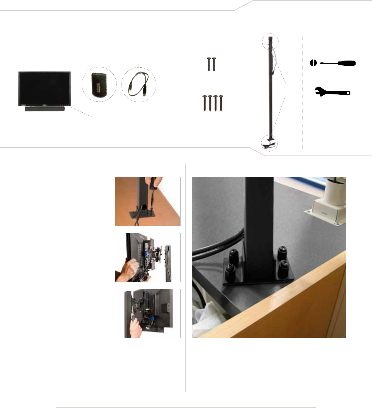
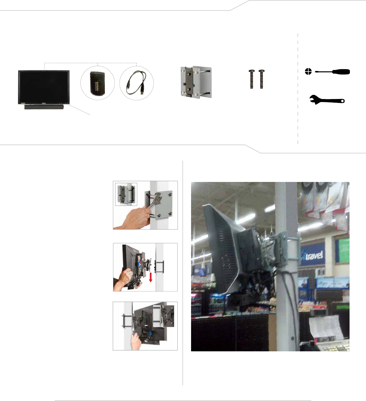
Stand-alone Square Post Surface Mount
A1. Stand-alone Square Post Surface Mount
1. Using the four Square Post
Mounting Screws, secure the
Square Post Mount to the counter,
making sure that the Monitor
Mount faces the queue.
2. Mount the Qtrac Unit onto to the
Post Monitor Mount by sliding the
Monitor-Mount Assembly onto the
Post-Mount Assembly.
3. Secure with 2 Bracket-to-Bracket
Mounting Screws. Do NOT connect
cables and power cords until
the remote controls have been
installed.
Required Tools
Adjustable Wrench
Phillips Head Screwdriver
Square Post
Mount
(pre-wired)
2 Bracket-to-Bracket
Mounting Screws
Monitor-Mounted Bracket comes
pre-attached to back of monitor.
Qdrive comes pre-attached
to back of monitor.
USB Cord comes pre-
attached to back of monitor.
Qtrac® Unit
Qtrac® Installation and Operation: Monitor Installation
Parts List:
4- Wood Screws
Page 3© 2011 Lavi Industries. All Rights Reserved.
DO NOT PLUG THE QTRAC UNIT INTO A POWER SOURCE UNTIL ALL REMOTES HAVE BEEN INSTALLED.
Required Tools
Adjustable Wrench
Phillips Head Screwdriver
Square Post
Mount
(pre-wired)
2 Bracket-to-Bracket
Mounting Screws
U-Bolt
Components
A2. Post-to-pillar Surface Mount
Monitor-Mounted Bracket comes
pre-attached to back of monitor.
Qdrive comes pre-attached
to back of monitor.
USB Cord comes pre-
attached to back of monitor.
Monitor w/CPU (Qtrac
Unit)
5. Secure with 2 Bracket-to-
Bracket Mounting Screws. Do
NOT connect cables and power
cords until the remote controls
have been installed.
4. Mount the Qtrac Unit onto to
the Monitor-mount by sliding
the Monitor-mount Assembly
onto the Post-mount Assembly.
3. Secure the mid-section of
the Square Post Mount to the
in-store pillar with the provided
U-Bolt.
2. Position the Square Post Mount
flush against the in-store pillar,
making sure that the Monitor Mount
faces the queue. Secure the post
to the counter with 2 Square Post
Mounting Screws through the
L-bracket into the counter.
1. Remove one of the L-brackets
from the Square Post Mount.
Be sure to remove the one that
is on the opposite side of the
Post-Mounted Bracket.
Square Post mounted to in-store pillar
Parts List:
4- Wood Screws
Qtrac® Installation and Operation: Monitor Installation
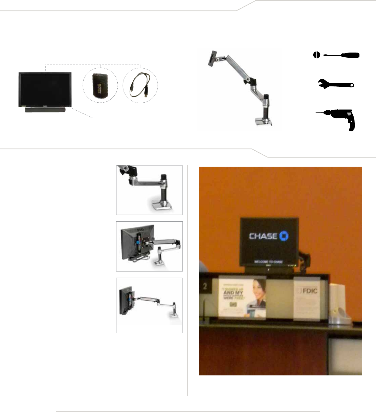
Page 4© 2011 Lavi Industries. All Rights Reserved.
DO NOT PLUG THE QTRAC UNIT INTO A POWER SOURCE UNTIL ALL REMOTES HAVE BEEN INSTALLED.
1. Attach the Cantilever Mount to the
back of the counter using the c-clamp
or by permanently screwing the base
of the mount into the counter.
2. Mount the Qtrac Unit to the Cantilever
Mount by securing the back of the
unit to the Vesa mounting plate on
the Cantilever Mount.
3. Fully extend the Cantilever Mount arm
so that the Qtrac Unit is positioned
appropriately and is viewable from
the queue.
Hide the Qtrac Unit’s power cords
within the Cantilever Mount’s wire
management system.
Do NOT connect cables and power
cords until the remote controls have
been installed.
Cantilever
Over-the-Counter Mount
A3. Cantilever Over-the-Counter Mount
Power Drill
Required Tools
Adjustable Wrench
Phillips Head Screwdriver
Monitor-Mounted Bracket comes
pre-attached to back of monitor.
Qdrive comes pre-attached
to back of monitor.
USB Cord comes pre-
attached to back of monitor.
Monitor w/CPU (Qtrac
Unit)
Parts List:
Qtrac Monitor with over-the-counter cantilever mount
Qtrac® Installation and Operation: Monitor Installation
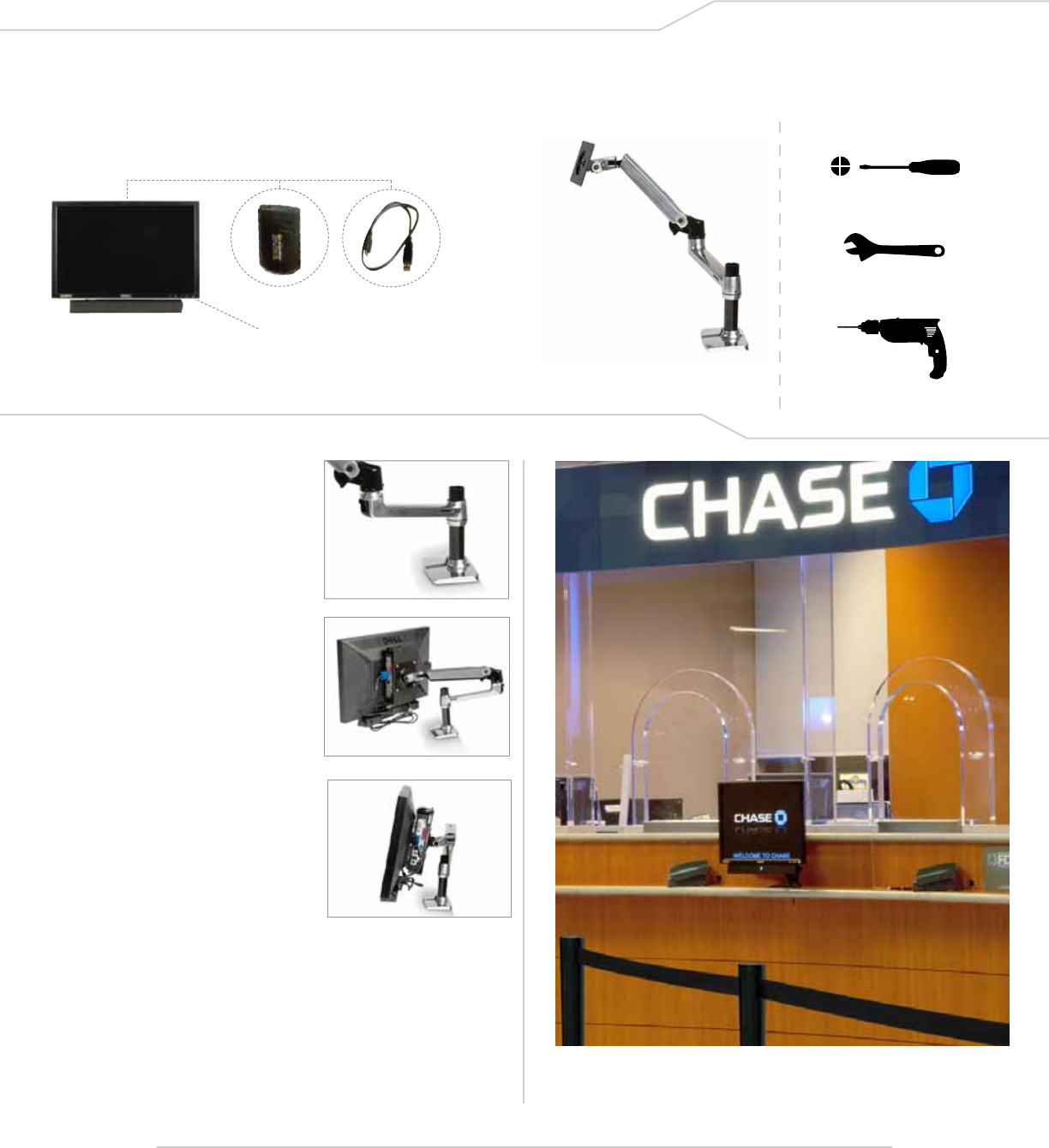
Page 5© 2011 Lavi Industries. All Rights Reserved.
DO NOT PLUG THE QTRAC UNIT INTO A POWER SOURCE UNTIL ALL REMOTES HAVE BEEN INSTALLED.
1. Attach the Cantilever Mount to the
front of the counter using the c-clamp
or by permanently screwing the base
of the mount into the counter.
2. Mount the Qtrac Unit to the Cantilever
Mount by securing the back of the
unit to the Vesa mounting plate on
the Cantilever Mount.
3. Fully collapse the Cantilever Mount
arm so that the Qtrac Unit is compact
and viewable from the queue.
Hide the Qtrac Unit’s power cords
within the Cantilever Mount’s wire
management system.
Do NOT connect cables and power
cords until the remote controls have
been installed.
A3. Cantilever Surface Mount (generally used in front of bullet-proof glass)
Power Drill
Required Tools
Adjustable Wrench
Phillips Head Screwdriver
Monitor-Mounted Bracket comes
pre-attached to back of monitor.
Qdrive comes pre-attached
to back of monitor.
USB Cord comes pre-
attached to back of monitor.
Monitor w/CPU (Qtrac
Unit)
Parts List:
Cantilever
Over-the-Counter Mount
Qtrac® Installation and Operation: Monitor Installation
Page 6© 2011 Lavi Industries. All Rights Reserved.
DO NOT PLUG THE QTRAC UNIT INTO A POWER SOURCE UNTIL ALL REMOTES HAVE BEEN INSTALLED.
1- Monitor-to-Post
Mounting Bracket
2- Monitor Bracket
Mounting Screws
1. Attach the Monitor-to-Post Mounting
Bracket to the desired post using an
adjustable wrench (not included),
making sure that the monitor
attachment faces forward.
2. Slide the Qtrac Unit onto the
Monitor-to-Post Mounting Bracket
until both pieces of the bracket are
firmly in place.
3. Insert Monitor Bracket Mounting
Screws on either side of the
Monitor-to-Post Mounting Bracket
and screw into place to secure Qtrac
Unit to post. Do NOT connect cables
and power cords until the remote
controls have been installed.
Front Back
Required Tools
Adjustable Wrench
Phillips Head Screwdriver
A4. Existing Pillar Mount
Monitor-Mounted Bracket comes
pre-attached to back of monitor.
Qdrive comes pre-attached
to back of monitor.
USB Cord comes pre-
attached to back of monitor.
Monitor w/CPU (Qtrac
Unit)
Parts List:
Qtrac Monitor mounted to existing in-store pillar
Qtrac® Installation and Operation: Monitor Installation
Page 7© 2011 Lavi Industries. All Rights Reserved.
Required Tools
Adjustable Wrench
Phillips Screwdriver
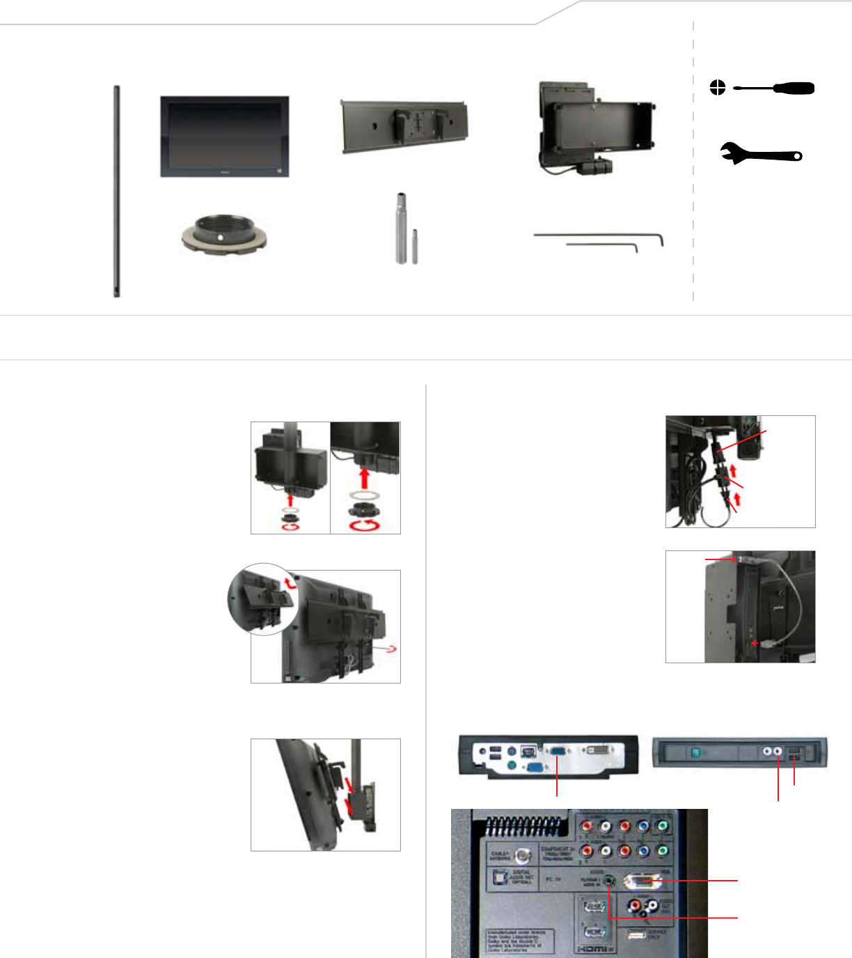
A5. Ceiling Mount
Peerless
Telescoping
Pole
Qtrac Monitor Ceiling Arm Box
Monitor Bracket
Retaining Collar
(shown here with the
ber washer) 2 Penta-Pin Tools*
(separated from the
Peerless Kit)
Special Allen
Wrenches*
* The smaller versions of both the Penta-Pin Tool and the Special Allen Wrench
have been provided in the event that you wish to tighten a pre-assembled part.
There may be no need to use either of them.
1. Attach the Ceiling Arm Box to
the Telescoping Pole that has
been installed per the product
instructions. The holes in the
Ceiling Arm Box are specially sized
to accommodate the pole. Follow
with the fiber washer and then the
Retaining Collar to secure the Ceiling Arm Box to the Pole.
3. Attach the Monitor/Bracket
Assembly to the Ceiling Arm
Box by sliding the monitor’s
bracket slots onto the large
bolts on the outer sides of the
Box. Then adjust the angle and
tighten all four bolts with the
large Penta-pin Tool.
6. Connect the Video and Audio Cables from the Monitor into
the back of the CPU.
2. Connect the Monitor Bracket
to the back of the Monitor by
sliding the upper lip of the
bracket into the slots of the
receiving channels on the back
of the Monitor. Slide up at an
angle, then in and down so the
bracket nests square and parallel to the back of the Monitor.
Use the Special Allen Wrenches to tighten the screws.
DO NOT TURN THE QTRAC UNIT ON UNTIL ALL REMOTES HAVE BEEN INSTALLED.
Parts List:
Qtrac® Installation and Operation: Monitor Installation
Before Getting Started: Be sure your Peerless Ceiling Mount has been installed according to the instructions that come with that product.
These instructions assume that the Telescoping Pole has been properly installed and wiring is available to continue with this installation.
ASSEMBLE AND INSTALL THE LARGE HARDWARE MAKE ALL POWER CONNECTIONS
CPU-Back
Monitor-Back
CPU-Front
Audio Port
Audio Port
QDrive
Video Port
Video Port
The ports will be clearly
marked on the back of
your Monitor.
5. The QDrive is pre-attached to the
CPU. Connect the QDrive’s USB
plug to the CPU’s USB port.
QDrive
4. Connect the CPU’s double-plug
(male end) into the available power
source that has been threaded
through the Pole, then plug the
Monitor’s AC plug into the CPU’s
double-plug (female side).
AC Power
Source,
threaded
through
the Pole.
Monitor AC Plug
CPU Double-Plug
Page 8© 2011 Lavi Industries. All Rights Reserved.
DO NOT PLUG THE QTRAC UNIT INTO A POWER SOURCE UNTIL ALL REMOTES HAVE BEEN INSTALLED.
Parts List:
Wireless Light
Controller
(1 for each light)
Station Light AC Adapter
(1 for each light)
Pre-wired Station Lights
(quantity varies per order/location)
Required Tools
Phillips Head Screwdriver
Drill
B1. Installing Qtrac Station Lights
Qtrac® Installation and Operation: Lights
1. Verify parts for this segment of Installation. Verify position of
lights and place each Station Light at corresponding station
along with their AC Adapters, Wireless Light Controllers and
Mounting Screws.
2. Drill a ½” hole in the designated
counter-tops in order to route
power cable for light.
3. Position the Station Light over the
drilled counter-top hole, feeding
the cord through the hole. Be sure
the Station Light faces the queuing
area. Secure with 4 Light Station
Mounting Screws.
4. Connect the pre-wired Station
Light Cord to the Station Light AC
Adapter.
5. Plug the power double-pronged
end of the Station Light AC Adapter
cord into the side of the Wireless
Light Controller with the “Z-Wave”
symbol (see inset). Plug the
Wireless Light Controller into the
power outlet.
6. Repeat steps 2–5 for all remaining Station Lights. Do NOT connect
cables and power cords until the remote controls have been installed.
4- Wood Screws
Qtrac Station Lights
Page 9© 2011 Lavi Industries. All Rights Reserved.
DO NOT PLUG THE QTRAC UNIT INTO A POWER SOURCE UNTIL ALL REMOTES HAVE BEEN INSTALLED.
1. Verify position of registers/lights and distribute the Wireless
Light Controllers to their respective stations. Each Wireless Light
Controller is numbered to correspond to a specific light number.
2. Plug the power cord for the existing
station light into the side of the
Wireless Light Controller with the
“Z-Wave” symbol (see inset). Plug
the Wireless Light Controller into the
power outlet.
3. Repeat steps 1–3 for all remaining registers/lights. Do NOT
connect cables and power cords on the Qtrac Unit until the
remote controls have been installed.
Wireless Light Controller
(1 for each register/light)
B2. Connecting Existing Station Lights
Qtrac® Installation and Operation: Lights
Parts List:
Page 10© 2011 Lavi Industries. All Rights Reserved.
THE QTRAC UNIT IS NOW READY FOR POWER-UP: SEE SECTION D, PAGE 11.
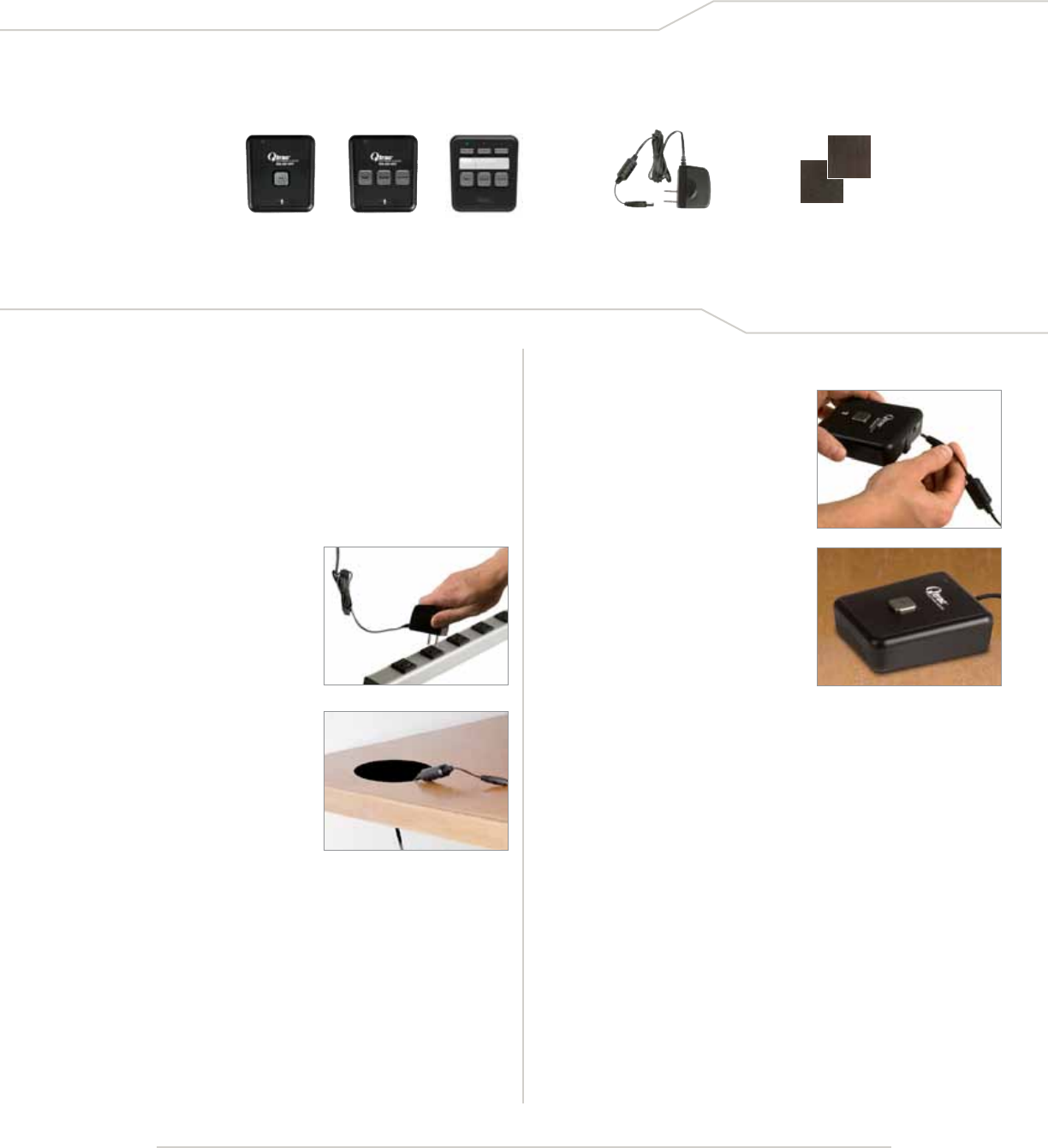
1. Each Remote is marked to correspond to a specific station.
Determine the correct location for each Remote Control
and distribute all Remotes with their AC Adapters to their
corresponding stations.
2. Plug the AC Adapter into an
AC wall outlet or power strip.
4. Connect the AC Adapter to the
Remote Control. The Remote
Control is now “ON”.
3. Route the Remote Control
AC Adapter through counter-top.
5. We recommend that you use the
supplied Velcro fasteners to secure
your Remote Control in place.
6. Repeat Steps 2–5 for each remaining Remote Control.
7. The Qtrac Unit is now ready for power-up, see section D,
Page 11.
Remote Controls
OR OR
Remote Control
AC Adapters
(1 per Remote)
Velcro Fasteners
(1 set per Remote)
C. Installing Remote Controls
Qtrac® Installation and Operation
Parts List:
Page 11© 2011 Lavi Industries. All Rights Reserved.
FOR TROUBLESHOOTING, PLEASE SEE PAGE 13 OF THIS GUIDE.
1. After all Remotes have been plugged
in, turn the Qtrac Unit “ON” by
connecting the power cables.
2. Then, turn the Monitor “ON” by
pressing the power button on the
front of the LCD panel.
Please wait up to 3 minutes while the
Qtrac Unit boots up and discovers
each wireless device.
Your Qtrac System is now ready
to use.
3. Test the Qtrac Unit by pressing the
“NEXT” button on each Remote
Control. Watch the screen to confirm
the appropriate queuing message.
4. Adjust the volume by turning the
knob on the right side of the speaker.
5. In between queuing messages,
the Monitor will display the default
media.
Pushing the “NEXT” button on any
of the Remotes interrupts the default
media with the appropriate queuing
message.
6. If different remote buttons are
pressed simultaneously, the arrow
messages will queue-up and play one
after the other until the sequence is
complete.
The system can remain powered up
at all times. There is no need to ever
shut it down.
D. Power-up and Basic Operation
Qtrac® Installation and Operation
Page 12© 2011 Lavi Industries. All Rights Reserved.
E. Qtrac Media Replacement
Qtrac® Installation and Operation
Changing or updating Qtrac informational media is simple and easy.
By following the simple step-by-step guidelines below, your
Qtrac system can be updated in just a few minutes.
Overview:
Qtrac informational media can be changed by simply inserting a USB drive with new media on it
into the Qtrac main computer which is normally located on the back of the Qtrac LCD display (monitor).
The new media on the USB drive will override the existing informational media that was pre-configured
on your Qtrac system and will start to play within seconds of inserting the new USB drive.
The new media will continue to play as long as the USB drive is inserted into the Qtrac computer. If the USB drive is removed, Qtrac will revert to playing
the informational media that was originally programmed onto the Qtrac system.
FORMATTING new media to play on the Qtrac system
Qtrac can play a still image slide show or a single video file between queuing messages, but it can’t play both. Please decide whether you will be
displaying still images or a single video file.
STILL IMAGES: Save as a JPEG or BMP and optimize to 60 using a software program that manipulates raster art such as
Adobe Photoshop, ImageReady, or Fireworks. Use the following pixel dimensions for the corresponding displays:
— Qtrac standard 22" monitor: 1680 x 945
— 32" TV: 1360 x 692
VIDEO: Create a video at 800 x 450 pixels, saving it as a WMV file (Windows Media Video) with a bit rate
of 2 mbps. If desired, you may also include an audio track in your video.
NAMING new media to play on the Qtrac system
Qtrac requires specific names for media files in order to recognize and play the files.
COPYING new media to a USB drive
Once created and named properly, new informational media files are ready to be added to your Qtrac system.
• Copy your new les to a blank USB drive.
• Files need to be loose and not contained within any folders.
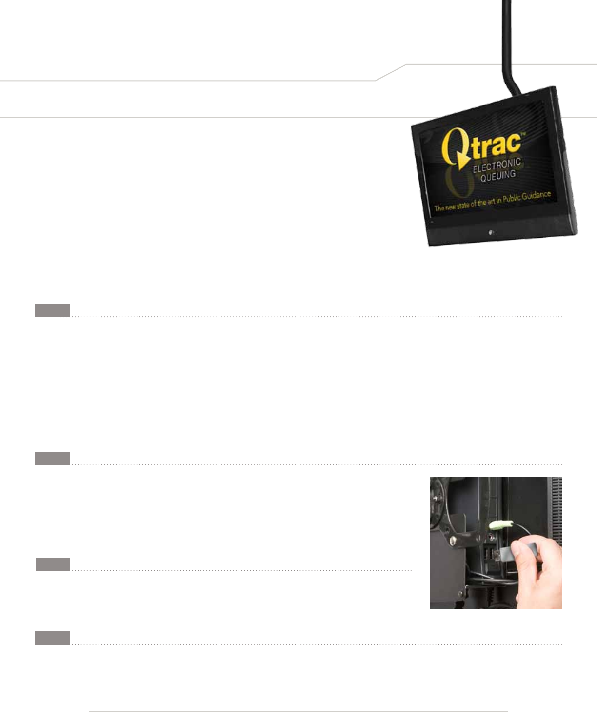
INSERTING the USB drive into the Qtrac CPU
You are now ready to update your informational media. Just insert the USB drive into any of the available USB ports on the Qtrac computer, which
is normally located on the back of the Qtrac LCD display (monitor). Qtrac should start playing the media immediately. To revert back to the originally
programmed media, simply remove the USB drive from the system.
STILL IMAGES (JPEG or BMP):
InfoDsp001.jpg or .bmp
InfoDsp002.jpg or .bmp
InfoDsp003.jpg or .bmp
(as many as needed)
VIDEO (WMV):
Media0.wmv
(Only 1 video file will be
recognized)
STEP 1:
STEP 2:
STEP 3:
STEP 4:
Insert a USB drive into the Qtrac to
immediately start playing new media.

Page 13
System is down due to power outage:
• If Qtrac does not automatically restart, turn on the CPU by pressing the blue button on the top of the CPU.
Blank monitor:
• Verify that both the monitor and the CPU are connected to power and turned on.
• Verify that the DVI/VGA cable from the CPU is rmly connected to the monitor.
• Verify that the monitor input is set to “auto detect”.
• Push button on the monitor to select menu.
• Use and to select Input Source option.
• Push to activate the Input Source option.
• Use and to select VGA (if blue cable is connected) or DVI-D (if white cable is connected).
• Push to confirm the selection.
No sound:
• Verify that the sound cable (cable with green connectors) is plugged into the audio jack on the CPU.
• Verify that the soundbar power cord (short cable with black connector) is plugged into the monitor.
• Turn the volume knob on the right side of the soundbar clockwise to turn on the speaker (solid white light should be visible on
the soundbar) and to adjust the volume.
Remote control is not responding:
• Verify that the remote control is plugged into the AC adapter.
• Verify that the AC adapter is plugged into power socket or power strip and that the power strip is plugged in and that the AC
cord has not been pulled loose.
• Verify that the remote control has a solid green light.
• Press “Next” button to test the remote control, if the problem persists, press the in-set ‘Learn’ button on the left side of the
remote control to reset the device.
• If the Qdrive is not plugged in, plug in the qdrive into a USB port on the CPU (ignore the windows pop-up screen) and turn the
computer off by pressing and holding the blue button on the top of the CPU.
• Turn the CPU on by pressing the blue button on the top of the CPU.
• Allow the CPU to boot and perform network discovery, and test the remote control.
Arrows do not correspond to the remote control locations:
Please contact Qtrac Specialist (Patti Miller) at:
Main Line: 800-624-6225 ext. 146
Direct Line: 661-219-3146
Systems Equipped with Station Lights
Station light does not blink:
• Verify that the station light is plugged in to the appliance module’s socket marked by z-wave logo.
Station light is not on:
• Verify that the appliance module is plugged into the AC outlet.
• Verify that the station light is plugged in to the appliance module’s socket marked by z-wave logo.
If you need assistance after business hours or on the weekend, please contact our On-Call staff: 800-545-4866
NOTE: Please specify that you have a Lavi Industries’ Qtrac system.
During weekday business hours 8:00 am – 5 pm PST, contact our Qtrac Specialist, Patti Miller:
Toll Free: 888-528-4872 • Direct Line: 661-219-3146 • Email: pattim@lavi.com
If the issue is not resolved after the items above have been addressed, please contact Customer Service:
E. Troubleshooting
27810 Avenue Hopkins | Valencia, CA 91355
800.624.6225 | 877.ASK.LAVI | 661.257.7800
sales@lavi.com | www.lavi.com 87-079 Qtrac Operation 03.15.11
© 2011 Lavi Industries. All Rights Reserved.
Products for People and the Places They Go®
Qtrac® Installation and Operation