LeapFrog 31500 2.4GHZ SDIO Module User Manual WN7911C LF manual 20140402
LeapFrog Enterprises, Inc. 2.4GHZ SDIO Module WN7911C LF manual 20140402
LeapFrog >
User manual rev

USER MANUAL
WN7911C-LF 1
USER MANUAL
WN7911C-LF
1x1 Single Band
802.11 b/g/n SDIO Carrier Module
V 0.1
.

USER MANUAL
WN7911C-LF 2
Table of Contents
1 Introduction ........................................................................................................................ 4
1.1 Introduction ........................................................................................................ 4
1.2 Product Features................................................................................................. 4
2 Hardware ............................................................................................................................ 5
2.1 General Overview .............................................................................................. 5
2.2 Block Diagram ................................................................................................... 6
2.3 Pin Description................................................................................................. 6
2.4 PCB Outline & Dimension............................................................................... 10
2.5 SDIO Connector Type ...................................................................................... 10
2.5.1 Board to Board Male (for Carrier Board) ................................................ 10
2.5.2 Board to Board Female (for Leapfrog Main Board) ................................ 11
2.5.3 Connector Mating (Mating Height 3 mm) ............................................... 11
3 Software ........................................................................................................................... 12
3.1 Driver Support.................................................................................................. 12
4 Specifications ................................................................................................................... 13
4.1 Frequency Band: .............................................................................................. 13
4.2 Transmit Power and Sensitivity: ...................................................................... 13
4.3 Modulation ....................................................................................................... 13
4.4 Current Consumption: ...................................................................................... 13
4.5 Temperature and Humidity............................................................................... 14
4.6 Regulatory and Certification Compliance................................................................ 14

USER MANUAL
WN7911C-LF 3
Revision History
Edition # Reason for revision Issue date Written by
V0.1 Initial document July 23, 2013 JC Chiou

USER MANUAL
WN7911C-LF 4
1 Introduction
1.1 Introduction
WN7911C is an industrial wireless IEEE 802.11n 1x1 2.4GHz single band SDIO module
which enables wireless networking systems to attain data transmission speeds up to 150
megabits-per-second (Mbps). The WN7911C maintains compatibility with legacy IEEE
802.11b.g devices. It supports operation to the IEEE 802.11b and IEEE 802.11g and IEEE
802.11n standards.
1.2 Product Features
Module form factor: 25mm x 18mm
O
perate at ISM frequency bands (2.4GHz)
SDIO interface for WiFi
IEEE standards support: IEEE 802.11b, IEEE 802.11g, IEEE 802.11n
Security features
WPA, WPA2, AES encryption/decryption
TKIP, 802.1x, WAPI encryption/decryption engine
USER MANUAL
WN7911C-LF 5
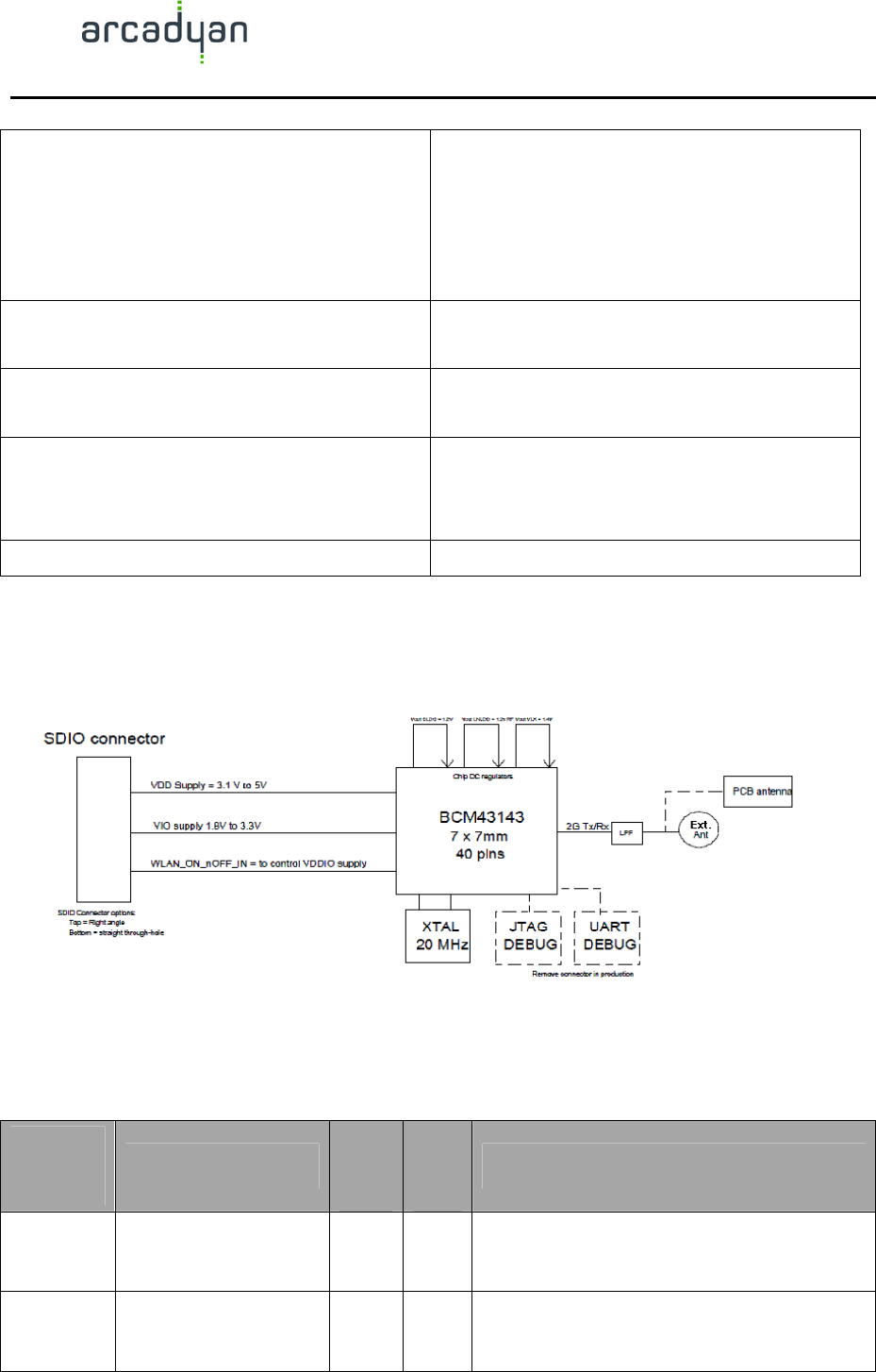
2 Hardware
2.1 General Overview
Module Dimension 25mm x 18mm
Module Interface SDIO v2.0 (50Mhz, 4-bit) host interface
Standard IEEE 802.11n, 802.11b/g
Chipset BCM43143 2.4GHz 802.11 1x1 b/g/n
MAC/PHY/Radio
Description 802.11 b/g/n 2.4GHz 1x1 WiFi carrier
module
Modulation 802.11b:
CCK, DQPSK, DBPSK
802.11g:
64 QAM, 16 QAM, QPSK, BPSK
802.11n:
BPSK, QPSK, 16-QAM, 64-QAM
Data Rate 8802.11b:
11, 5.5, 2, 1 Mbps;
802.11g:
54, 48, 36, 24, 18, 12, 9, 6 Mbps
802.11n:
MCS 0 to 7 for HT20MHz;
MCS 0 to 7 for HT40MHz
Operating Frequency Draft 802.11n Radio: 2.4 GHz
802.11g Radio: 2.4 GHz
802.11b Radio: 2.4 GHz
USA – FCC
2412~2462MHz (Ch1~Ch11)
Canada – IC
2412~2462MHz (Ch1~Ch11)
Europe – ETSI
2412~2472MHz (Ch1~Ch13)
Japan – STD-T66/STD-33
2412~2484MHz (Ch1~Ch14)
USER MANUAL
WN7911C-LF 6
Operating Channel WiFi 2.4GHz:
11: (Ch. 1-11) – United States
13: (Ch. 1-13) – Europe
14(ch1-14)– Japan
2.400GHz ~ 2.4835 GHz
Antenna Connector One antenna allowing transmission or
reception on both, simultaneously
Operating System Supported
Linux
Temperatures Operating Temperature: -10°C to +70 °C
Storage Temperature: -40°C to +80°C
(non-operating):
Humidity 5-90
2.2 Block Diagram
2.3 Pin Description
Pin
Number Terminal Name
Pin
Type
I/O
Type
Description
1 BTCX_RF_ACTIVE Signal
I Indicates that the coexistent BT is active:
internal pull-down.
2 BTCX_STATUS Signal
I Indicates the coexistent BT priority status and
RX/TX direction.

USER MANUAL
WN7911C-LF 7
3 USB_AVDD12 Power
I USB Phy core 1.2V supply
4 USB_AVDD25 Power
I USB Phy analog 2.5V supply
5 USB_AVDD33 Power
I USB Phy analog 3.3V supply
6 VDD_AFE Power
I 1.2V filtered supply for ADC; 1.2V filtered
supply for AFE AUX
7 GND Power
I Ground
8 USB20_DEV_DPLS Signal
I/O USB port data plus
9 USB20_DEV_DMNS Signal
I/O USB port data minus
10 GND Power
I Ground
11 BTCX_FREQ Signal
I
Indicates that the coexistent BT is about to
transmit on a restricted channel: internal
pull-down.
12 GPIO_8 Signal
I/O General-purpose interface pins.
13 BTCX_TXCONF Signal
O Output permission for the coexistent BT to
transmit.
14 UART_TX Signal
O Serial Input for UART
15 UART_RX Signal
I Serial Output for UART
16 GND Power
I Ground
17 VIN_LDO Power
I Input supply pin for CLDO and LNLDO1
18 VDD_CORE_1.2V Power
O 1.2V output for core LDO, 200mA
19 VDD_RADIO_PLL_O
Power
O 1.2V output for low noise LNLDO1, 150mA
20 VDD_3.3V Power
O Internal PALDO output or feedback of output
from external PNP
21 GPIO_0 Signal
I/O General-purpose interface pins.
22 VDD_2.5V Power
O 2.5V LDO2p5 output
23 GND Power
I Ground
24 VLX Power
O Core buck regulator: Output to inductor
25 VIN_3V_5V Power
I Battery supply input for PALDO;
USER MANUAL
WN7911C-LF 8
Core buck regulator: Battery voltage input
26 GPIO_2 Signal
I/O General-purpose interface pins.
27 GND Power
I Ground
28 SDIO_CLK Signal
I/O SDIO clock
29 GPIO_3 Signal
I/O General-purpose interface pins.
30 SDIO_DATA_0 Signal
I/O SDIO data line 0
31 GPIO_1 Signal
I/O General-purpose interface pins.
32 SDIO_DATA_1 Signal
I/O SDIO data line 1
33 SDIO_DATA_2 Signal
I/O SDIO data line 2
34 GPIO_9 Signal
I/O General-purpose interface pins.
35 RESETn Signal
I
Low asserting global chip reset: digital input
pin.
Used by PMU to enable/disable power the
internal regulators.
36 SDIO_CMD Signal
I/O SDIO command line
37 SDIO_DATA_3 Signal
I/O SDIO data line 3
38 VDDIO Power
I
Digital I/O supply (1.8V to 3.3V)
VDDIO should be supplied externally;
SDIO I/O supply (1.8V to 3.3V)
39 GND Power
I Ground
40 VDD_PLL Power
I
1.2V supply for PLL;
1.2V crystal oscillator filtered power supply
41 GND Power
I Ground
42 VDD_RADIO_PLL_I Power
I 1.2V supply for radio transmit and receive
sections
43 GND Power
I Ground
44 GND Power
I Ground
USER MANUAL
WN7911C-LF 9
45 GND Power
I Ground
46 ANT Signal
I/O Antenna port
47 GND Power
I Ground
48 VDD_3.3V Power
I
RF I/O supply (2.6V to 3.3V);
3.3V OTP power supply (no lower than
3.0V);
3.3V for the internal power amplifiers
G1 GND Power
I Ground pad
G2 GND Power
I Ground pad
G3 GND Power
I Ground pad
G4 GND Power
I Ground pad
G5 GND Power
I Ground pad
G6 GND Power
I Ground pad
G7 GND Power
I Ground pad
G8 GND Power
I Ground pad
G9 GND Power
I Ground pad
G10 GND Power
I Ground pad
G11 GND Power
I Ground pad
G12 GND Power
I Ground pad
G13 GND Power
I Ground pad
USER MANUAL
WN7911C-LF 10
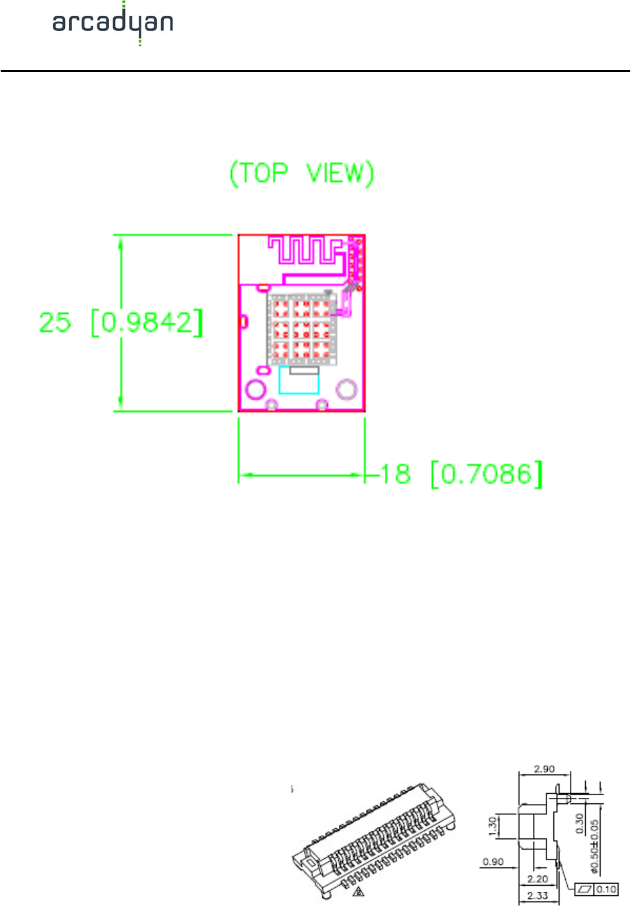
2.4 PCB Outline & Dimension
2.5 SDIO Connector Type
2.5.1 Board to Board Male (for Carrier Board)
ACC Part Number: NPV014S07R-H

USER MANUAL
WN7911C-LF 11
Unit: mm
2.5.2 Board to Board Female (for Leapfrog Main Board)
ACC Part Number: NPV014P23R-H
Unit: mm
2.5.3 Connector Mating (Mating Height 3 mm)

USER MANUAL
WN7911C-LF 12
Unit: mm
3 Software
3.1 Driver Support
Android
Linux
Windows CE (check for the availability)

USER MANUAL
WN7911C-LF 13
4 Specifications
4.1 Frequency Band:
802.11n Radio: 2.4 GHz
802.11b/g Radio: 2.4 GHz
4.2 Transmit Power and Sensitivity:
TX Output Power: (Typical)
11b 16 +/- 1 dBm
11g 10.5+/- 1 dBm
11n 10 +/- 1 dBm
Rx Sensitivity: (Typical)
-86 dBm @11 Mbps
-72 dBm @54 Mbps
-68 dBm @64-QAM, 20MHz channel spacing
-61 dBm @64-QAM, 40MHz channel spacing
4.3 Modulation
DBPSK @1Mbps
DQPSK@2Mbp
CCK@5.5/11Mbps
BPSK@6/9 Mbps
QPSK@12/18Mbps
16-QAM@24Mbps
64-QAM@48/54Mpb and above, up to 300Mbps
4.4 Current Consumption:
TX: 263mA x 3.3V Max
RX: 81.58mA x 3.3V Max
Power Saving: 1.25mA x 3.3V
Deep sleep mode: 130uA

USER MANUAL
WN7911C-LF 14
4.5 Temperature and Humidity
Operating Temperature: 0 ~ 40
o
C ambient (TBD)
Storage Temperature: -10 ~ 70
o
C ambient (TBD)
Humidity: 5 ~ 90% and must be non-condensing (TBD)
4.6 Regulatory and Certification Compliance
TBD
The drawings, specifications and the data contain herein are the exclusive property of Arcadyan
Technology Corp. issued in strict confidence and shall not, without the prior written permission of
Arcadyan Technology Corp., be reproduced, copied or used, in parts or as a whole, for any purpose
whatsoever, except the manufacture of articles for Arcadyan Technology Corp.
Arcadyan makes no warranties with respect to the correctness, accuracy or wholeness of this
specification. The information in this document is subject to change without notice. Arcadyan
reserves the right to make revisions to this document and the product described herein without
obligation to notify any person or entity of any such changes.
WARNING
This document is intended for internal use only. A Non-Disclosure Agreement (NDA)
is required to release this document under any circumstances

USER MANUAL
WN7911C-LF 15
Federal Communication Commission Interference Statement
This device complies with Part 15 of the FCC Rules. Operation is subject to the following two
conditions: (1) This device may not cause harmful interference, and (2) this device must accept
any interference received, including interference that may cause undesired operation.
This equipment has been tested and found to comply with the limits for a Class B digital device,
pursuant to Part 15 of the FCC Rules. These limits are designed to provide reasonable
protection against harmful interference in a residential installation. This equipment generates,
uses and can radiate radio frequency energy and, if not installed and used in accordance with
the instructions, may cause harmful interference to radio communications. However, there is
no guarantee that interference will not occur in a particular installation. If this equipment does
cause harmful interference to radio or television reception, which can be determined by turning
the equipment off and on, the user is encouraged to try to correct the interference by one of the
following measures:
- Reorient or relocate the receiving antenna.
- Increase the separation between the equipment and receiver.
- Connect the equipment into an outlet on a circuit different from that
to which the receiver is connected.
- Consult the dealer or an experienced radio/TV technician for help.
FCC Caution: Any changes or modifications not expressly approved by the party responsible
for compliance could void the user's authority to operate this equipment.
This transmitter must not be co-located or operating in conjunction with any other antenna or
transmitter.

USER MANUAL
WN7911C-LF 16
Radiation Exposure Statement:
This equipment complies with FCC radiation exposure limits set forth for an uncontrolled
environment. This equipment should be installed and operated with minimum distance 20cm
between the radiator & your body.
This device is intended only for OEM integrators under the following conditions:
1) The antenna must be installed such that 20 cm is maintained between the antenna and
users, and
2) The transmitter module may not be co-located with any other transmitter or antenna.
As long as 2 conditions above are met, further transmitter test will not be required. However,
the OEM integrator is still responsible for testing their end-product for any additional
compliance requirements required with this module installed
IMPORTANT NOTE: In the event that these conditions can not be met (for example certain
laptop configurations or co-location with another transmitter), then the FCC authorization is no
longer considered valid and the FCC ID can not be used on the final product. In these
circumstances, the OEM integrator will be responsible for re-evaluating the end product
(including the transmitter) and obtaining a separate FCC authorization.
End Product Labeling
This transmitter module is authorized only for use in device where the antenna may be installed
such that 20 cm may be maintained between the antenna and users. The final end product must
be labeled in a visible area with the following: “Contains FCC ID: QDX31500”. The grantee's
FCC ID can be used only when all FCC compliance requirements are met.
Manual Information To the End User
The OEM integrator has to be aware not to provide information to the end user regarding how
to install or remove this RF module in the user’s manual of the end product which integrates
this module.
The end user manual shall include all required regulatory information/warning as show in this
manual.

USER MANUAL
WN7911C-LF 17
Industry Canada statement:
This device complies with RSS-210 of the Industry Canada Rules. Operation is subject to the
following two conditions: (1) This device may not cause harmful interference, and (2) this
device must accept any interference received, including interference that may cause undesired
operation.
Ce dispositif est conforme à la norme CNR-210 d'Industrie Canada applicable aux appareils
radio exempts de licence. Son fonctionnement est sujet aux deux conditions suivantes: (1) le
dispositif ne doit pas produire de brouillage préjudiciable, et (2) ce dispositif doit accepter
tout brouillage reçu, y compris un brouillage susceptible de provoquer un fonctionnement
indésirable.
Radiation Exposure Statement:
This equipment complies with IC radiation exposure limits set forth for an uncontrolled
environment. This equipment should be installed and operated with minimum distance 20cm
between the radiator & your body.
Déclaration d'exposition aux radiations:
Cet équipement est conforme aux limites d'exposition aux rayonnements IC établies pour un
environnement non contrôlé. Cet équipement doit être installé et utilisé avec un minimum de
20 cm de distance entre la source de rayonnement et votre corps.

USER MANUAL
WN7911C-LF 18
This device is intended only for OEM integrators under the following conditions: (For module
device use)
1) The antenna must be installed such that 20 cm is maintained between the antenna and users,
and
2) The transmitter module may not be co-located with any other transmitter or antenna.
As long as 2 conditions above are met, further transmitter test will not be required. However,
the OEM integrator is still responsible for testing their end-product for any additional
compliance requirements required with this module installed.
Cet appareil est conçu uniquement pour les intégrateurs OEM dans les conditions suivantes:
(Pour utilisation de dispositif module)
1) L'antenne doit être installée de telle sorte qu'une distance de 20 cm est respectée entre
l'antenne et les utilisateurs, et
2) Le module émetteur peut ne pas être coïmplanté avec un autre émetteur ou antenne.
Tant que les 2 conditions ci-dessus sont remplies, des essais supplémentaires sur l'émetteur ne
seront pas nécessaires. Toutefois, l'intégrateur OEM est toujours responsable des essais sur
son produit final pour toutes exigences de conformité supplémentaires requis pour ce module
installé.
IMPORTANT NOTE:
In the event that these conditions can not be met (for example certain laptop configurations or
co-location with another transmitter), then the Canada authorization is no longer considered
valid and the IC ID can not be used on the final product. In these circumstances, the OEM
integrator will be responsible for re-evaluating the end product (including the transmitter) and
obtaining a separate Canada authorization.
NOTE IMPORTANTE:
Dans le cas où ces conditions ne peuvent être satisfaites (par exemple pour certaines
configurations d'ordinateur portable ou de certaines co-localisation avec un autre émetteur),
l'autorisation du Canada n'est plus considéré comme valide et l'ID IC ne peut pas être utilisé
sur le produit final. Dans ces circonstances, l'intégrateur OEM sera chargé de réévaluer le
produit final (y compris l'émetteur) et l'obtention d'une autorisation distincte au Canada.

USER MANUAL
WN7911C-LF 19
End Product Labeling
This transmitter module is authorized only for use in device where the antenna may be
installed such that 20 cm may be maintained between the antenna and users. The final end
product must be labeled in a visible area with the following: “Contains IC: 4810A-31500”.
Plaque signalétique du produit final
Ce module émetteur est autorisé uniquement pour une utilisation dans un dispositif où
l'antenne peut être installée de telle sorte qu'une distance de 20cm peut être maintenue entre
l'antenne et les utilisateurs. Le produit final doit être étiqueté dans un endroit visible avec
l'inscription suivante: "Contient des IC: 4810A-31500".
Manual Information To the End User
The OEM integrator has to be aware not to provide information to the end user regarding how
to install or remove this RF module in the user’s manual of the end product which integrates
this module.
The end user manual shall include all required regulatory information/warning as show in this
manual.
Manuel d'information à l'utilisateur final
L'intégrateur OEM doit être conscient de ne pas fournir des informations à l'utilisateur final
quant à la façon d'installer ou de supprimer ce module RF dans le manuel de l'utilisateur du
produit final qui intègre ce module.
Le manuel de l'utilisateur final doit inclure toutes les informations réglementaires requises et
avertissements comme indiqué dans ce manuel.