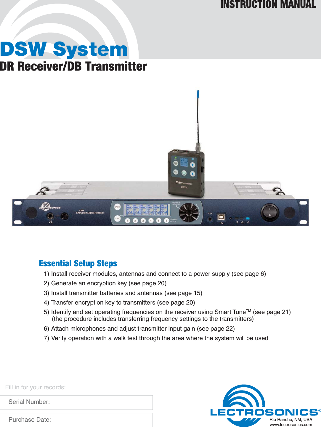
Lectrosonics DB Wireless Microphone Transmitter User Manual DSW SystemManual

Lectrosonics Inc Wireless Microphone Transmitter DSW SystemManual

Users Manual

DSW SystemDR Receiver/DB TransmitterINSTRUCTION MANUALRio Rancho, NM, USAwww.lectrosonics.comFill in for your records:  Serial Number:  Purchase Date:Essential Setup Steps1) Install receiver modules, antennas and connect to a power supply (see page 6)2) Generate an encryption key (see page 20)3) Install transmitter batteries and antennas (see page 15)4) Transfer encryption key to transmitters (see page 20)5) Identify and set operating frequencies on the receiver using Smart TuneTM (see page 21)  (the procedure includes transferring frequency settings to the transmitters)6) Attach microphones and adjust transmitter input gain (see page 22)7) Verify operation with a walk test through the area where the system will be used
DSW Digital Wireless SystemLECTROSONICS, INC.2
DSW Digital Wireless SystemRio Rancho, NM 3IntroductionDSW (Digital Secure Wireless) is designed for no-com-promise applications where performance and security are the highest priority.A completely new digital architecture was developed for the DSW wireless system. Extended operating range rivals the best analog and Digital Hybrid Wire-less® systems, with remarkable audio quality and only 2.5 ms of latency. The system operates on standard UHF FCC Part 74 frequencies (TV channel band).256-bit encryption is applied to the transmitted signal stream for security against eavesdropping. The algo-rithm conforms to the AES 256-CTR standard.DR Modular ReceiverThe DR receiver is a 1RU modular, six-channel design with a host mainframe that contains the DSP, micro-processor, antenna multicoupler and control interface. Receiver modules are installed on either side of the mainframe. No tools are required to remove and install the receiver modules. Each module will tune across a 25.6 MHz range.Antenna ports on the rear panel accept input from remote antennas, with a “loop-thru” output to another mainframe. A high quality internal multicoupler distrib-utes the RF signal to the receiver modules.For rack mount installations, a kit is available to mount antenna inputs (BNC connectors) on the receiver front panel using a coaxial cable routed through the receiver chassis to the rear panel connections.DB Belt Pack TransmitterThe DB belt pack transmitter is encased in a solid machined aluminum housing with a membrane switch panel and backlit LCD interface. The servo bias input circuitry will work with a wide variety of microphones and line level sources, Input gain is adjustable over a wide range in 1 dB steps to optimize the signal to noise ratio and dynamics of the audio.The transmitter tunes across the entire frequency range of the DSW system, from 470 MHz to 691 MHz.Table of ContentsEssential Setup Steps ..........................................................1Introduction ............................................................................3Receiver Front Panel .............................................................4Headphone output ...............................................................4LCD and control Interface ....................................................4Encryption key and settings transfer port .............................4USB Port ..............................................................................4Comm LED ..........................................................................4Alert LED .............................................................................4Power LED ...........................................................................4Receiver Rear Panel ..............................................................5Antenna connections ...........................................................5Audio Outputs ......................................................................5Ethernet Port ........................................................................5AES Word Clock ..................................................................5RS-232 Port .........................................................................5Antenna Cable Front Panel Pass-thru ..................................5Power Supply .......................................................................5Hardware Installation ............................................................6Receiver Modules ................................................................6Antenna Connections ...........................................................6Audio Output Wiring - Analog ...............................................6Audio Output Wiring - AES3 Digital ......................................7Connections for Computer Interface ....................................7RS-232 Port Pinouts ............................................................7Ethernet Port ........................................................................7Receiver LCD Interface .........................................................8Navigating the Menus ..........................................................9Menu Map and Icons .........................................................10Software Installation ...........................................................13Windows Installation ..........................................................13Mac Installation ..................................................................14Connecting to a Network ....................................................14Using DHCP for IP Address Assignment ...........................14DB Transmitter .....................................................................15Features and Functions .....................................................15DB Transmitter LCD Interface ............................................15Powering On in Operating Mode ........................................16Powering On in Standby Mode ..........................................16Powering Off ......................................................................16Power Menu .......................................................................16Navigating Menus ..............................................................17Adjusting LCD Backlight ....................................................17Locking/Unlocking Changes to Settings.............................17Selecting Programmable Switch Functions........................17Other Menu Items ..............................................................17DB Transmitter Menu Map .................................................18Copying Transmitter Settings To and From the Receiver ...19System Setup .......................................................................20Specifications ......................................................................24Service and Repair ..............................................................25Returning Units for Repair .................................................25FCC Notice ...........................................................................26
DSW Digital Wireless SystemLECTROSONICS, INC.4Receiver Front PanelHeadphone outputA standard 1/4 inch jack and volume control knob LCD and control InterfaceAll settings for the receiver and transmitter can be adjusted from the receiver front panel.Encryption key and settings transfer portA cable between the transmitter and this port on the receiver is used to transfer the encryption key from the receiver to the transmitter. This connection can also be used to send the transmitter settings stored in the receiver to the transmitter.The interface cable, P/N DRKEYCABLE, is used to make this connection.USB PortA standard USB port is used to connect to a computer for system setup and monitoring.Comm LEDThe LED blinks blue to indicate USB, RS-232 and ethernet communication.Alert LEDThis LED blinks to indicate fault or error, and glows white during firmware updates.Power LEDThe LED glows blue to indicate power is turned on.Headphone outputLCD and control inferface for system setupEncryption key and settings transfer portUSB portComm LEDAlert LED Power LEDRotary encoder
DSW Digital Wireless SystemRio Rancho, NM 5Receiver Rear PanelAntenna connectionsStandard 50 ohm BNC jacks accept input from the an-tennas. A built-in multi-coupler distributes the antenna signal to the six receiver modules, and also to the OUT jack to deliver the signal to an additional receiver.Audio OutputsEach XLR connector provides a balanced analog output. AES-EBU digital audio is provided on jacks 1, 3 and 5 as marked on the rear panel.Ethernet PortNetwork connection is provided on a standard RJ-45 connector.(   ) (   )AESWORDCLOCKANTPWRAES5 & 6 AES3 & 4 AES1 & 2ANTPWRAntenna input A Antenna input BAntenna loop-thru outputAntenna loop-thru outputRS-232 serial portDigital audio word clock portsEthernet portBalanced audio outputs channels 1 - 3Audio outputs channels 4 - 6AES output channelsAES output channelsAntenna cable front panel pass-thruAES Word ClockThe receiver can sync to an external clock signal or generate a clock signal and function as the master.RS-232 PortFor use with third party control systems or a direct connection to a PC.Antenna Cable Front Panel Pass-thruA coaxial cable can be routed from the rear panel BNC connectors to BNC connectors on the left and right side of the front panel. The coaxial cable is routed through the inside of the receiver chassis.Power SupplyThe receiver is powered from an external power sup-ply, 10 –18 VDC, 4A.
DSW Digital Wireless SystemLECTROSONICS, INC.6Antenna ConnectionsConnect the antennas or coaxial cables to the antenna input connectors labeled IN on the rear panel.Note:  The frequency bandwidth of the antennas must cover the range of the modules in use.For multiple unit installations, a “loop thru” is available to feed two or three receivers from a single antenna pair. Connect coaxial cables from the multicoupler out-puts on the first receiver to the antenna inputs on the next receiver in the stack.(   ) (   )AESWORDCLOCKANTPWRAES5 & 6 AES3 & 4 AES1 & 2ANTPWR(   ) (   )AESWORDCLOCKANTPWRAES5 & 6 AES3 & 4 AES1 & 2ANTPWR(   ) (   )AESWORDCLOCKANTPWRAES5 & 6 AES3 & 4 AES1 & 2ANTPWR  The upper connectors are the inputs connected to the antennas on the first unit in the stack. The lower connectors are the outputs that feed the next as-sembly lower in the rack.Audio Output Wiring - AnalogThe analog audio output wiring is as follows: (+)1(-)SHIELD SHIELD(+)(-)23(+)1(-)SHIELD SHIELD(+)23(+)1(-)SHIELD SHIELD(+)23DROutputAudioInputBalanced with 3-wire cableUnbalanced with 3-wire cableUnbalanced with 2-wire cableHardware InstallationReceiver ModulesThe DR mainframe/host assembly is a wideband design that coves the entire available frequency range. Individual receiver modules are available in 25.6 MHz frequency “blocks.” Any module can be installed in any of the six mainframe positions without regard to the frequency tuning range. Module positions correspond to the rear panel audio outputs as shown here.Front panel123456Installing Receiver Modules1.  Turn the mainframe power off.  The receiver modules interface with the main as-sembly through multi-pin connectors on either side of the chassis. Insert the module straight down and then slide it toward the main housing to insert the connector pins. The module should sit flush against the side of the housing. Retaining clipCaution:  Make sure the connectors align correctly. Do not apply excessive force to seat the module onto the tab.2. Align the ridge on the retaining clip with the slot in the chassis and press the clip downward until the ridge snaps into the slot in the side panel.Removing Receiver Modules1. Turn the mainframe power off.2. Remove the retaining clip by pressing the top side-ways to release it from the slot in the side panel. Then pull upward to remove it.3.  Pull outward on the module to release the connec-tor and then lift it upward out of the chassis. Holes in the underside of the chassis allow you to grip the module on the top and bottom.
DSW Digital Wireless SystemRio Rancho, NM 7Audio Output Wiring - AES3 DigitalXLR output connectors deliver digital audio that con-forms to the AES standard. The wiring is the same as a balanced analog output.Pin 1 Ground/Shield Pin 2 Data (+) Pin 3 Data (–)Pins 2 and 3 carry the digital audio. Although polarity is not an issue, it is good practice to maintain a “pin to pin” connection - pin 1 to pin 1, pin 2 to pin 2, pin 3 to pin 3 in cables that terminate in XLR connectors at both ends. It is best to use 110 ohm cable designed to carry digital signals. Conventional microphone cables may cause problems, especially with distances over 30 or 40 feet.For pinout details of wiring to a DB-25 connector, refer to the documentation for the device you are using.Channel assignments per connector are marked on the rear panel of the receiver.Connections for Computer InterfaceConnection to a computer for set up is easiest with a single or multiple USB connection.USB HubNOTE:  Audio is not passed through the USB port. It is used only for control and monitoring settings.Receivers can also be connected via RS-232 ports on PCMCIA cards and remote control systems.(   ) (   )AESWORDCLOCKANTPWRAES5 & 6 AES3 & 4 AES1 & 2ANTPWR(   ) (   )AESWORDCLOCKANTPWRAES5 & 6 AES3 & 4 AES1 & 2ANTPWRControl SystemCom 1Com 2RS-232 Port Pinouts123456789123456789DCDRXTXDTRGNDDSRRTSCTSRITXRXGNDHost Serial Port (PC)DR RS-232 PortDTE pin functionsFemale connectorMale connectorDCE pin functionsFemale jackMale jackEthernet PortA standard RJ-45 connector is provided for network interfacing. This port is used for setup, monitoring and control with Wireless Designer software and third party control devices.
DSW Digital Wireless SystemLECTROSONICS, INC.8Receiver LCD InterfaceAll settings can be made from the front panel keypad and LCD interface, including transmitter settings if it is connected to the receiver with the key cable. The con-trol interface consists of membrane switches, a rotary encoder with push switch and a graphical LCD.Press a channel select button to open a setup screenPress the center of the rotary encoder to open the menu select screenSelected receiverSelected item is enclosed in markersTurn the rotary encoder to select the option at the bottom of the screen. Press the center of the rotary encoder to open the setup screen or menu for the se-lected item. In the example below, the setup screen for channel 3 is open, with the frequency in MHz selected.Selected item is highlighted with ruled lines above and belowPress the center of the rotary encoder and then turn it to adjust the value of the selected item.When the desired value is set, press the center of the rotary encoder to deselect the item. Rotate the encod-er to select the next item.Press one of the numbered switches under the display to open a setup screen for the corresponding chan-nel. Press the BACK button to return to the previous screen. Press the center of the rotary encoder to open the menu selector screen.There are three levels in the menu structure:s Top Menu includes links to the RX and TX menus and setup screens for system parameters such as frequency scanning, encryption key generation and configuring hardware connections.s RX Menu includes setup screens for the receiver parameters and a link back to the Top Menu.s TX Menu includes setups screens for the transmitter and a link back to the Top Menu.Rotate the encoder to scroll through the menu items. Select the desired item and press the encoder to enter the next menu or setup screen.In the RX and TX menus, a link is included in the left-most position to return to the Top Menu.You can also press the BACK button on the control panel to return to the previous screen or menu.Lower bar describes the highlighted menuTop bar lists active menuMain Window displays a summary of all channels
DSW Digital Wireless SystemRio Rancho, NM 9Navigating the MenusFrom the Main Window, press the encoder to open the menu select screen.Lower bar describes the highlighted menuTop bar lists active menuThe menu selections includes links to the RX and TX menus and system level choices. Rotate the encoder to select the desired item.The example shown below is for the SMART NR menu item. The navigation is the same for all menu items. The icon in the center of the LCD, highlighted in blue, is the active (selected) menu item.Press the encoder to enter the setup screen.Top bar shows currently selected menuLower bar describes the selected menu itemSince there are up to six channels in the receiver, the channel must be selected before entering the setup screen. After the menu item is selected, as shown above, press the encoder to move to the the next screen, which allows you to navigate to the desired channel. The selected channel appears on top of the graphical “stack” in the display. Active menuSelected channel Menu titleEnter setup screen markers indicate selected functionThe “stack” of available channelsRotate the encoder to select the “CHOOSE” item in the lower bar (markers indicate active selection). Press the encoder to highlight the item.Once the icon is highlighted, rotate the encoder to scroll through the available channels. The rectangular icon will move to indicate the selected channel.Rectangular icon will indicate the selected channelAfter the desired channel is selected, press the en-coder to remove the highlight, then rotate it to select EDIT (markers indicate the selected item) and press the encoder to highlight the item and enter the setup screen to make changes.EDIT item highlighted when setup screen is activeWhen the EDIT item is highlighted, the setup screen for the selected channel will be active. Rotate the encoder to the desired setting that appears inside the rectangular area (NORMAL in this illustration), then press the BACK button on the panel to store the set-ting and leave the setup screen.Press the BACK button again to return to the menu. Press it once or twice again to return the previous menu or the main window that displays a summary of all channels.NOTE:  Refer to the menu map on the following pages for an overview of the menus.
DSW Digital Wireless SystemLECTROSONICS, INC.10Menu Map and IconsReceiver and transmitter setup or adjustments to settings can be completed using the receiver LCD interface. The menus are organized into three groups, as shown here.The TOP MENU includes system setup and connec-tions, frequency scanning and selection, and encryp-tion key generation and transfer to transmitters for overall system setup. Links to the TX and RX menus are located at the leftmost position.TOP MENUDETECT identifies the installed receiver modules. SMART TUNE launches a spectrum scan of any one or more of the installed receiver modules and identifies prospective operating frequencies. A frequency is selected and a screen prompt appears on the LCD allowing you to connect a transmitter and load the frequency settings or skip to the next scan.SPECTRUM SCAN is useful for manually examining the RF activity within the tuning range of the installed modules. The scanned results appear in a histogram that can be browsed with coarse or fine detail.KEY TRANSFER loads the encryption key into the transmitter via the key cable. KEY MANAGEMENT is used to generate or delete an encryption key, and to configure the nature of the key as Persistent or One-time.LOCK PANEL is used to lock out the front panel controls, create a password or leave the controls unlocked.BACK LIGHT adjusts the appearance of the LCD. ANTENNA POWER inserts DC voltage on the rear panel BNC jacks to power remote RF amplifiers such as the one in the Lectrosonics ALP650 model LPDA “shark fin” antenna. The BNC jacks can be configured independently.DETECT SMART TUNESPECTRUM SCANKEY TRANSFERKEYMANAGEMENTSENDSETTINGSTX BATTERY TX AUDIO GAINLF ROLLOFF TX PHASEFREQ ADJUST AUDIO LEVEL MONITOR AUDIOSMART NR PHASETOP MENUTX MENURX MENU
DSW Digital Wireless SystemRio Rancho, NM 11The TX MENU (transmitter menu) is used to config-ure and store the settings for all transmitters that will be used in the system. These settings, stored in the receiver memory, can be transferred from the receiver to the transmitter during setup with the key cable. A link back to the Top Menu is located at the leftmost position.RX MENU (receiver menu) includes menu items for each receiver module to set up operating parameters and options. A link back to the Top Menu is located at the leftmost position.NETWORK SETUP configures the IP address and other credentials for network connections through the ethernet port.RS232 SETUP sets the baud rate of the RS232 port. COMMAND VIEW is used to send hand typed commands from a computer directly to a connected receiver, and display the response that comes back on the computer screen. It is helpful for testing commands during development of programs for 3rd party controllers, and to send a batch of commands from a file to configure or test the receiver.SYSTEM INFO displays the receiver serial number, firmware version and hardware version. Active Alerts will also appear on the list, if there are any.TX MENUTransmitters can be configured in the receiver and the settings can then be sent to the transmitter via the USB cable.SEND SETTINGS transfers the settings for the transmitter configuration that are stored in the receiver to the attached transmitter. The transfer is made via the key cable.TX BATTERY is used to make the battery status monitor more accurate, since the behavior of alkaline and lithium batteries is different across their life during use.TX AUDIO GAIN adjusts the transmitter input gain to optimize the signal to noise ratio and dynamic range of the system with voices or signal sources, different microphones and microphone positions.LOCK PANEL BACK LIGHT ANTENNA POWERNETWORK SETUPRS232 SETUP COMMAND VIEWSYSTEM INFOPROG SWITCH AUTO ON TX PANEL LOCKBATT TIMER TX BACKLIGHTAUDIO OUTPUTMODULE POWER
DSW Digital Wireless SystemLECTROSONICS, INC.12(TX MENU cont’d)LF ROLLOFF adjusts the point at which the low frequency audio in the transmitter begins to roll off. This “knee” can be set at 35, 50, 70, 100, 120 or 150 Hz.TX PHASE reverses the polarity of the audio signal in the transmitter to match other microphones in the system that vary with different microphone types and connector wiring.NOTE:  The audio polarity on each output channel on the receiver can also be reversed in the RX MENU.PROG SWITCH configures the function of the switch located on the outside of the housing on the transmitter. The switch can be config-ured to be an audio mute switch, a power on/off switch or to be disabled.AUTO ON sets the transmitter to either turn back on and resume operation after a battery change, or to require being manually turned back on again.NOTE:  The AUTO ON feature works only when the RF output carrier is turned on.TX PANEL LOCK prevents inadvertent changes to be made on the transmitter keypad. The menus can still be browsed to view the settings, but changes cannot be made.BATT TIMER is used to determine the remaining battery life based upon a test of the batteries in use. This is especially useful when rechargeable batteries are being used. Reset the time with the setup screen. Charge the batteries fully, then run them down in the transmitter with the timer running to determine the available runtime. TX BACKLIGHT adjusts the length of time that the backlight remains lit on the transmit-ter LCD. Options are 30 seconds, 5 minutes or to remain on.RXMENUFREQ ADJUST allows manual selection of the operating frequency. AUDIO LEVEL provides a setup screen with adjustments of the analog audio output level for each channel, plus a tone output on each channel for use in adjusting the input level of a con-nected device or sound system.MONITOR AUDIO adjusts the level of each channel that appears at the headphone jack on the front panel. Options include individual output level, program audio, or tone and either isolated channel monitoring or a mix of all channels.SMART NR (smart noise reduction) allows the selection of the noise reduction mode on each channel. Options include NORMAL, FULL and OFF.PHASE inverts the polarity of the analog audio outputs on the receiver. AUDIO OUTPUT selects analog or AES digital modes for the receiver outputs. Adja-cent modules are paired in the selection.MODULE POWER turns each receiver module on or off.
DSW Digital Wireless SystemRio Rancho, NM 13Software InstallationThe supplied software for the DSW system is available on disk or downloaded from the web site at:www.lectrosonics.com/wdsupportThe software will run on Windows or Mac computers. The procedure for installing it varies between down-loaded and disk versions.Windows InstallationNOTE: Uninstall any previous version before installing this software.Disk Installation:The installation procedure is straightforward following the on-screen instructions. Insert the disk into a local drive. If the installer does not launch automatically,When the first screen appears, click on Install Wire-less Designer Software/USB Driver.Click on Install Wireless Designer to launch the installer.After a few moments, the Setup Wizard will appear. Click on Next to continue.Installation with downloaded file:A screen listing the components to be installed will ap-pear. All three boxes should be checked, then click on Install to continue.When the License Agreement screen appears, click on I agree and the installation will proceed. When the installation is complete, a confirmation screen will ap-pear. Click on Finish, wait a moment and then remove the disk from the drive.
DSW Digital Wireless SystemLECTROSONICS, INC.14Mac InstallationLaunch your browser and go to:http://lectrosonics.com/wdsupport/xap/WirelessDe-signer.htmlWhen the Wireless Designer intro screen appears, right click and choose Install Wireless Designer onto this computer...You may need to install an updated version of Silver-light before completing the installation.Connecting to a NetworkUsing DHCP for IP Address AssignmentFollow these steps to make a network connection for the receiver:1)  Open Wireless Designer and connect to the receiver via USB. 2)  Click on Settings in the left pane. Then click on the Network tab in the lower part of the screen. Inside the dialog box labeled Network Settings, click on the check box labeled DHCP Enable.3) Close Wireless Designer.4)  Connect the network cable to the Ethernet port on the rear panel.5)  Turn the receiver power off then back on.6)  Launch Wireless Designer again and navigate to Network Settings as described above. The IP address and port number will appear in the dialog box.7)  Close the USB connection and re-connect via network. When the dialog box opens, enter the IP address and the port number noted, then click on Refresh. Click on OK to connect.
DSW Digital Wireless SystemRio Rancho, NM 15DB TransmitterSteve494.500-40 -20 0MUTEBattery status LEDKey verification LEDPower buttonMenu navigation buttonsReturn to previous screenUSB port for firmware updatesProgrammable function switchAntenna portMicrophone/Line input jackDB Transmitter LCD InterfaceThe Main Window displays the transmitter name, block number, Standby or Operating mode, transmitting fre-quency, audio level, battery status and programmable switch function.Steve494.500-40 -20 0MUTEFrequency (MHz)RF indicatorBattery statusProgrammable switch functionAudio levelTransmitter nameNOTE: The transmitter name that appears on the LCD is created with the software and downloaded to the transmitter with the USB cable connected.In the Standby Mode the RF indicator icon will blink to indicate that the RF output is turned off.Steve494.500-40 -20 0MUTEWhen the programmable switch is set to Mute and is turned on, the mute icon appearance will change and the word MUTE will blink at the bottom of the display, and the power/function LED will blink blue.Steve494.500MUTE<–MUTE–>Features and FunctionsThe keypad and LCD interface provides access to settings and adjustments. A toggle switch on the top panel is programmable to operate as an audio mute switch, a power switch or be inoperative. This allows the transmitter to be configured with full access to all settings, or as a simple one-button device with settings locked.The transmitter is powered by three AA batteries in series. To open the battery compartment, slide the door outward in the direction indicated by the engraved arrows on the door, and swing it open. The correct ori-entation of the batteries is illustrated on the rear panel of the transmitter.Battery orientation engraved on back panelSlide door out and swing open3.5mm TRS plug Micro USB connectorP/N:  DRKEYCABLE
DSW Digital Wireless SystemLECTROSONICS, INC.16Powering On in Operating ModePress and hold the Power Button   until a counter on the LCD progresses from 1 to 3. When you release the button, the unit will be operational with the RF output turned on and the Main Window displayed.HoldforRf On...3Steve494.500-40 -20 0MUTERF indicatorPowering On in Standby ModePressing the Power Button   and releasing it before the counter has reached 3 will turn the unit on with the RF output turned off. In this Standby Mode the menus can be browsed to make settings and adjust-ments without the risk of interfering with other wireless systems nearby.Steve494.500-40 -20 0MUTEHoldforRf On...1Release Power Button before the counter reaches 3 to enter standby modeRF indicator blinksAfter settings and adjustments are made, turn the unit off by pressing and holding the power button until a countdown on the LCD is completed.NOTE:  Also see the topic entitled Power Menu for other options.Powering OffPowering  O . . .1From any screen, power can be turned off by holding the Power Button   in and waiting for the countdown, selecting Pwr Off in the power menu, or with the program-mable switch (if it is configured for this function).If the power button is released, or the top panel switch is turned back on again before the countdown is com-pleted, the unit will remain turned on and the LCD will return to the same screen or menu that was displayed previously.NOTE: If the programmable switch is in the OFF position, power can still be turned on with the power button.Power MenuPressing the power button   when the unit is turned on will display a menu with several options:s Resume returns to the previous screen and operat-ing state.s Rf On? opens a dialogue screen with options to turn  the RF output on or off.s AutoOn? opens a dialogue screen with options to either automatically restore power after batteries have been replaced, or leave the unit turned off after batteries have been replaced.s Pwr Off starts the power off sequence countdown.ResumeRf On?AutoOn?Pwr OffResume and Pwr Off will execute the command immediatelyResumeRf On?AutoOn?Pwr OffThe other two menu items will open a screen asking for a Yes or No answer.Rf On?NoYe sResumeRf On?AutoOn?Pwr OffAutoOn?NoYe sResumeRf On?AutoOn?Pwr Off
DSW Digital Wireless SystemRio Rancho, NM 17Navigating MenusThe LCD/keypad interface makes it easy to browse the menus and make the selections for the setup you need. When the unit is powered up in either the operat-ing or the standby mode, press MENU/SEL on the keypad to enter a menu structure on the LCD. Use the  and   arrow buttons to select the menu item. Then press the MENU/SEL button to enter the menu.-40 -20 0Gain25The prompt in the upper right corner may display one or both arrows, depending upon what adjustment can be made. If the changes are locked, a small padlock symbol will appear.GainFreq.ProgSwRolloffAdjusting LCD BacklightFor viewing the LCD in dimly lit conditions, the back-light can be turned on continuously or set to turn off automatically after either 30 seconds or 5 minutes.BacklitAboutDefaultWipeKeyyBacklitOn30 sec5 minLocking/Unlocking Changes to SettingsChanges to the settings can be locked.Locked?BacklitAboutDefaultLocked?NoYe s -40 -20 0Gain25A small padlock symbol will appear on adjustment screens when changes have been locked.When changes are locked, several controls and ac-tions can still be used:s 3ETTINGSCANSTILLBEUNLOCKEDs -ENUSCANSTILLBEBROWSEDs 0ROGRAMMABLESWITCHSTILLWORKSs 0OWERCANSTILLBETURNEDOFFBYUSINGTHEPOWERmenu or removing the batteries.Selecting Programmable Switch FunctionsThe programmable switch on the top panel can be configured using the menu to provide several func-tions:s (none) - disables the switchs Mute - mutes the audio when switched ons Power - turns the power on and offProgSwRolloffPhaseBatTypeProgSw(none)MutePowerUse the   and   arrow buttons to select the desired function or disable the switchNOTE: The programmable switch will continue to operate whether or not keypad changes are locked.Other Menu ItemsRefer to the table and descriptions on the following page for an explanation of the menu items.
DSW Digital Wireless SystemLECTROSONICS, INC.18DB Transmitter Menu MapFrom the main window, navigate with the arrow buttons to the desired menu item and press MENU/SEL to enter the setup screen.SELBACKFreq.Select option with arrow buttonsUse arrow buttons to select value 22Gain SELBACKGainLevel meter at bottom of screenFreq.470.675Press MENU/SEL to highlight MHz or kHzSELBACKProgSw(none)MutePowerSELBACKRolloffRolloff 50 Hz Select value with arrow buttonsSELBACKPhase NormalInvertPhaseSELBACKBatType Alk.Lith.BatTypeSELBACKBatTimeSELBACKLocked?YesNoLocked?SELBACKBacklitBacklitOn30 sec5 minDisplays model number and firmware revisionSELBACKAboutDBV1.01AboutBat 5:41Reset?YesNoSELBACKDefaultDefaultSettingsNoYesSelect value with arrow buttonsSelect option with arrow buttonsSelect option with arrow buttonsSelect option with arrow buttonsSelect option with arrow buttonsSelect option with arrow buttonsSelect option with arrow buttonsSELBACKWipeKeyNoYesWipeKey?Select option with arrow buttonsAfter the desired selection if made, press BACK to return to the menu.Gain -  This setting determines the signal to noise ratio and dynamic range that the system will deliver. Review the setup procedure care-fully for optimal performance.Freq. - Frequency can be set manually.ProgSw - The programmable switch on the top panel of the transmitter can be configured for different functions with this setup menu.Rolloff - The low frequency audio rolloff is adjustable to optimize performance for envi-ronmental conditions or personal preference.Phase - The polarity of the audio signal can be reversed to match other microphones in the system. Differences in polarity are due to microphone designs and connector wiring.BatType - This setting makes the battery sta-tus display more accurate, since alkaline and lithium batteries behave differently as they are discharged.BatTime - A built-in timer can be used with any battery type, but it is especially valuable with rechargeable batteries such as NiMH types. The voltage remains fairly constant across the discharge time of a rechargeable battery, then drops quickly near the end of the operating time. The most accurate way to determine runtime status is by testing the time provided by a particular battery brand and type, then using a timer to determine remain-ing runtim.Locked? - The keypad can be locked out to prevent inadvertent changes to be made.Backlit - The brightness and appearance of the LCD can be adjusted for better viewing in different lighting conditions.About - Displays the firmware revision.Default - The factory default settings can be restored with this single setup screen.WipeKey - The encryption key can be erased with this setup screen.
DSW Digital Wireless SystemRio Rancho, NM 19Copying Transmitter Settings To and From the ReceiverConnect the key cable from the jack labeled KEY on the front of the receiver to the micro USB port on the side of the transmitter.If transmitter settings are defined in the receiver, they can be transferred to a connected transmitter, or cop-ied from a transmitter to a receiver channel using the key cable.Transmitter Settings ScreenPress MENU/SEL and navigate to the TX MENU, then to the SEND SETTINGS (microphone) icon. Press the encoder to enter the transmitter settings screen.Select the desired channel with the CHOOSE TX op-tion at the bottom of the screen.Send Settings to TransmitterAfter the channel is selected, highlight the SEND SET option at the bottom of the screen. Connect the transmitter with the USB cable and press the encoder to start the transfer.The transmitter LCD will display RECEIVED when the settings have successfully transferred.If the transfer cannot be completed, an error message will appear.Get Settings from TransmitterThe settings in the transmitter can be transferred to the receiver for storage or editing with the GET SET option in the setup screen.The transmitter must be turned fully on and tuned to the selected channel on the receiver.Select the desired channel and then the GET SET option. Turn the transmitter fully on with the RF output enabled and press the encoder to start the transfer. An error message will appear if no RF signal is being received.NOTE:  Settings will be displayed on the Transmitter Settings screen, but changes are not made here. Settings are adjusted in the TX MENU as described on previous pages, on the transmitter itself, or with the Wireless Designer software.
DSW Digital Wireless SystemLECTROSONICS, INC.20System SetupThese instructions apply to setup using the front panel LCD. If you will be using Wireless Designer for setup, instructions are in the help files supplied with the soft-ware.Install Receiver ModulesTurn power off on the DR mainframe. Install the mod-ules as needed. Any module can be installed in any position in the mainframe assembly. When the power is turned on, the modules will be detected during the bootup sequence and an icon for each one will appear on the LCD.Generate Encryption KeyOn the receiver LCD, navigate to the KEY MANAGE-MENT item in the Top Menu and press the encoder to enter the setup screen.In this setup screen, the type of encryption key policy can be set, a new key generated or the existing key can be deleted.The encryption key policy can be configured as:s 0%23)34%.4s /.%4)-%+%9A PERSISTENT key will remain in receiver and trans-mitter memory until it is replaced with a new key or manually deleted using WIPE KEY in the menus.A ONE-TIME ONLY key is used for maximum secu-rity. The key exists only as long as the power on both receiver and transmitter remains on during a single session. If a transmitter is powered off, but the receiver has remained turned on, the key must be sent to the transmitter again. If the power is turned off on the receiver, the entire session concludes and a new key must be generated and sent to all transmitters.In either key policy, there are 256 “instances” available each time a new key is generated. “Instance” refers to a transfer of the key from receiver to transmitter. Each instance contains a unique key. The number of instanc-es is reduced each time a key is transferred. When the number of instances reaches 10, a warning will be displayed on the LCD.Select the NEW KEY option and press the encoder to enter the setup screen.NOTE: It is generally more convenient to use a PERSISTENT key during setup, since power may be need to be cycled on and off on the transmitters or receiver until the system is completely set up.The stored key can be deleted manually with the WIPE KEY option.Initial Transmitter SetupAttach the antenna and install the batteries into the transmitters that will be used. Turn the power on and observe the BATT LED on the transmitter. Verify that the batteries are fresh or fully charged (the LED will glow green with good batteries).Transfer Encryption Key to TransmittersOn the receiver LCD, navigate to the KEY TRANSFER item in the Top Menu and press the encoder to enter the setup screen. YES indicates the transmitter is connectedConnect the transmitter with the key cable and press the encoder to start the transfer. The LED on the top right corner of the keypad will glow blue when the key has been transferred successfully.NOTE: The key can be transferred with the transmitter either fully powered up or in the standby mode with the RF output turned off.
DSW Digital Wireless SystemRio Rancho, NM 21Frequency SelectionManual selection may be necessary if frequencies are mandated by an authority, such as a major sporting event. You can manually set the frequencies and set-tings for the transmitters in the receiver, then connect a transmitter and transfer settings. Or, of course, just manually set the frequency in each receiver channel and transmitter.Using Smart TuneTM is the easiest way to find and set good operating frequencies. The process scans the tuning range of designated channels, identifies a good operating frequency and prompts the operator to connect a transmitter and transfer the settings. The transfer can be completed or skipped, and scanning will then continue with the next receiver.Manual Frequency SelectionFrom the Main Window, press the numbered channel select button under the LCD on the front panel to open the receiver setup screen. Rotate the encoder to select the EDIT option.Press the encoder to highlight the EDIT option and then rotate the encoder to select the left or right hand frequency item. The left hand item adjusts frequency in 1 MHz steps, and the right hand item adjusts frequen-cy in 25 kHz steps. Selected item is indicated with ruled lines above and belowPress the encoder to highlight the selected item and then rotate it to set the frequency. Then press the encoder to de-highlight it, rotate the encoder to select the other frequency item and press the encoder to highlight it.Adjust in 1 MHz steps Adjust in 25 kHz stepsAfter adjusting the frequency, press the BACK but-ton on the front panel or the encoder to de-highlight the item. Then press the BACK button to leave the EDIT option. Use the SEL RX option or return to the Main Window to move to another receiver to adjust its frequency.Selected receiverSelect the SEL RX option and press the encoderPress the encoder to de-highlight SEL RX. Select the EDIT option and repeat the above procedure.Using Smart TuneTM for Frequency SelectionWhen new frequencies must be discovered, this auto-matic frequency scanning and setup function is by far the easiest and quickest way to get up and running.Select the SMART TUNE item in the Top Menu and press the encoder to open the setup screen.A check box next to each receiver indicates whether or not the channel will be included in the scanning and setup process. Press the channel select buttons on the keypad below the LCD to check or uncheck each channel. Normally, a single scan on each channel is adequate to identify good operating frequencies. If you prefer, up to 10 scans can be performed on each frequency. Select the number of scans with the NUM SCAN PASS option.Selects the number of scans on each channel
DSW Digital Wireless SystemLECTROSONICS, INC.22Select BEGIN in the setup screen and press the en-coder to start the process. Scanning will proceed one at a time on each receiver, from the lowest numbered one to the next higher numbered one.Each scan pass takes about 20 seconds. After the scan on the first receiver is completed, the receiver will be set to the newly identified frequency. A mes-sage will appear on the LCD, prompting to connect a transmitter and transfer the settings from the receiver. To set up the transmitter, turn its power on, connect it with the USB cable, select SEND TX SET and press the encoder to start the transfer.Transmitter setup can also be skipped at this time and set up later.NOTE: It is best to set up transmitters when prompted, and leave them turned on for subsequent scans, so their signals will be included in finding clear spectrum for new frequencies.Navigate to the TX MENU on the receiver and select the desired channel. Connect a transmitter to the receiver with the USB cable. Select the SEND SET op-tion at the bottom of the screen and press the encoder.After all frequencies have been selected and settings have been transferred to the transmitters, finish the transmitter setup by adjusting the input gain on each one to match the user’s voice with the microphone in the position it will be used.Attach Microphone and Adjust Transmitter GainThis adjustment is very important to optimize the sig-nal to noise ratio and dynamic range that the system is capable of delivering.It is best to go through the following procedure with the transmitter in the standby mode so that no audio will enter the sound system or recorder during adjustment.1) With fresh batteries in the transmitter, power the unit on in the standby mode (see previous section Pow-ering On in Standby Mode).2) Navigate to the Gain setup screen.GainFreq.ProgSwRolloff -40 -20 0Gain25-40 -20 0Gain25Peak audio level indication3) Position a microphone the way it will be used in actual operation and have the user speak or sing at the loudest level that will occur during use, or set the output level of the instrument or audio device to the maximum level that will be used.4) Use the   and   arrow buttons to adjust the gain until the peak indicator on the audio level display flickers during loud audio passages.NOTE: The peak indicator does not mean the audio is distorted. It simply means full modulation has been achieved. The input limit will cleanly handle increased levels up to 30 dB above this point.5) Once the audio gain has been set, the signal can be sent through the sound system for overall level adjustments, monitor settings, etc. 6) Always leave the transmitter gain adjustment set according to these instructions. Adjustment only needs to be made if a different person, microphone, microphone placement, or a different instrument is used. Do not change it to adjust the audio output level of the receiver. If the audio output level of the receiver is too high or low, use only the controls on the receiver to make that adjustment.
DSW Digital Wireless SystemRio Rancho, NM 23Adjust Receiver Analog Audio Output LevelThe analog audio output of the receiver is set at maxi-mum, and lower levels are achieved with an attenuator to reduce the signal level to match the level require-ments of other equipment. This means that there is no difference in signal to noise ratio regardless of where the receiver output level control is set. Any time gain is applied to the audio signal, noise is also added. The best approach is to use as much output on the receiver as possible with the least amount of gain on the connected device. Following this principle, it is generally best to use a line input on the connected device to avoid additional gain that might be applied to a microphone input.A tone generator is provided in the receiver to al-low accurate input level adjustment of the connected device. This steady tone is the same as the maximum level that will appear at the outputs. The outputs can be set between -35 dBu and +8 dBu, in 1 dB steps. For example, if a channel is set at +0, the maximum output that will appear at that output is +0 dBu when the transmitter is driven to full modulation (the onset of limiting).The simple and accurate way to match the receiver output with the input of the connected device is using the following procedure.1) Turn the output of the DR receiver all the down (-35 but not OFF).2) Turn the input of the connected device all the way down, but not OFF.3) Turn the tone on and gradually increase the output level of the receiver while observing the input level meter on the connected device. Increase the level until the input level meter indicates full scale. OVROVR-200-10-200-10Input Level Meter on Connected DeviceNominal levelIf the receiver output is turned all the way up and the nominal level on the input meter is not achieved, turn the gain on the connected device input up gradually until a full scale reading is indicated.NOTE: If the transmitter is driven hard into limiting, up to 30 dB, the output level of the receiver will be a few dB above this nominal level.Once the input level on the connected device is set, turn the tone generator off in the menu. The generator will turn off automatically when you return to the Main Window.When the receiver output and connected device input are set up in this manner, there is no need to change these settings from one event to another. As micro-phones and microphone placement change, and with different voices, the only adjustment needed is the input gain on the transmitter.
DSW Digital Wireless SystemLECTROSONICS, INC.24SpecificationsSystemOperating Frequencies:  470.100 - 691.175 MHz in 25 kHz stepsSampling Size and Rate:  24-bit, 48 kHzDigital Modulation:  8PSKSymbol rate:  128 kData Compression:  Proprietary ADPCMEncryption: AES 256-CTR     (per FIPS 197 and FIPS 140-2)System Latency:  2.5 msAudio Frequency Response:  20 - 20 kHz, +/- 1 dBDistortion:  0.05% THD+N, 1 kHz @ -10dBFSDynamic Range:  108 dB A-wtd, NR=NORMALDR ReceiverSensitivity:  -98 dBm for 10-5 BERDiversity Technique:  Noiseless antenna switchingAntenna Inputs:  Dual BNC female, 50 ohm impedanceAudio Outputs:   XLR:  Balanced, -35 to +8 dBu analog     or AES3 digital   Headphone:  1/4 inch phone jackExternal DC Power:  10 to 18 VDC; 40 Watts max.Weight:  6.58 lbs.; 2984 gramsDimensions:  19 x 1.75 x 10.6 in.     483 x 44 x 269 mm.DB TransmitterRF Output Power:  50 mWSpurious Emissions:  >90 dB below carrierAudio Input Jack:  TA5F 5-pin lockingEquivalent Input Noise:  -128 dBVInput Impedance:  Mic:  300 ohms     Line: 2k ohmsInput Limiter:  Dual envelope type; 30 dB rangeGain Control Range:  44 dB in 1 dB steps; digital controlLF rolloff:  -3 dB @ 35, 50, 70, 100, 120, 150 HzAntenna Connection:  SMA; 50 ohmsBattery:  Three AA Duracell Quantum recommendedBattery Life:  TBAWeight:  7.4 ozs. (211 grams)     with 3 alkaline AA batteriesDimensions:  3.4 x 2.5 x .74 in. (86 x 62 x 19 mm)
DSW Digital Wireless SystemRio Rancho, NM 25Service and RepairIf your system malfunctions, you should attempt to correct or isolate the trouble before concluding that the equip-ment needs repair. Make sure you have followed the setup procedure and operating instructions. Check the inter-connecting cables and then go through the Troubleshooting section in this manual.We strongly recommend that you do not try to repair the equipment yourself and do not have the local repair shop attempt anything other than the simplest repair. If the repair is more complicated than a broken wire or loose con-nection, send the unit to the factory for repair and service. Don’t attempt to adjust any controls inside the units. Once set at the factory, the various controls and trimmers do not drift with age or vibration and never require readjustment. There are no adjustments inside that will make a malfunctioning unit start working.LECTROSONICS’ Service Department is equipped and staffed to quickly repair your equipment. In warranty repairs are made at no charge in accordance with the terms of the warranty. Out-of-warranty repairs are charged at a mod-est flat rate plus parts and shipping. Since it takes almost as much time and effort to determine what is wrong as it does to make the repair, there is a charge for an exact quotation. We will be happy to quote approximate charges by phone for out-of-warranty repairs.Returning Units for RepairFor timely service, please follow the steps below:A. DO NOT return equipment to the factory for repair without first contacting us by email or by phone. We need to know the nature of the problem, the model number and the serial number of the equipment. We also need a phone number where you can be reached 8 A.M. to 4 P.M. (U.S. Mountain Standard Time).B. After receiving your request, we will issue you a return authorization number (R.A.). This number will help speed your repair through our receiving and repair departments. The return authorization number must be clearly shown on the outside of the shipping container.C. Pack the equipment carefully and ship to us, shipping costs prepaid. If necessary, we can provide you with the proper packing materials. UPS is usually the best way to ship the units. Heavy units should be “double-boxed” for safe transport.D. We also strongly recommend that you insure the equipment, since we cannot be responsible for loss of or dam-age to equipment that you ship. Of course,  we insure the equipment when we ship it back to you.Lectrosonics USA:Mailing address:    Shipping address:    Telephone: Lectrosonics, Inc.    Lectrosonics, Inc.    (505) 892-4501 PO Box 15900    561 Laser Rd.  Ste. 102  (800) 821-1121 Toll-free Rio Rancho, NM 87174  Rio Rancho, NM  87124   (505) 892-6243 Fax USA    USA    Web:    E-mail: www.lectrosonics.com   sales@lectrosonics.com
DSW Digital Wireless SystemLECTROSONICS, INC.26FCC NoticeNOTE:  This equipment has been tested and found to comply with the limits for a Class B digital device, pursuant to Part 15 of the FCC Rules. These limits are designed to provide reasonable protection against harmful interference in a residential installation. The equipment generates, uses and can radiate radio frequency energy and, if not installed and used in accordance with the instructions, may cause harmful interference to radio communications. However, there is no guarantee that interference will not occur in a particular installation. If this equipment does cause harmful interference to radio or television reception, which can be determined by turning the equipment off and on, the user is encouraged to try to correct the interference by one or more of the following measures:s 2EORIENTORRELOCATETHERECEIVINGANTENNAs )NCREASETHESEPARATIONBETWEENTHEEQUIPMENTANDreceivers #ONNECTTHEEQUIPMENTINTOANOUTLETONACIRCUITdifferent from that which the receiver is connecteds #ONSULTTHEDEALERORANEXPERIENCEDRADIO46TECH-nician for helpChanges or modifications to this equipment not ex-pressly approved by Lectrosonics, Inc. could void the user’s authority to operate it.
DSW Digital Wireless SystemRio Rancho, NM 27
31 October 2014&%$* $#o,*(((!'%$&$# &$"**)*&!&!'%$&$# &$"LIMITED ONE YEAR WARRANTYThe equipment is warranted for one year from date of purchase against defects in materials or workmanship provided it was purchased from an authorized dealer. This warranty does not cover equipment which has been abused or damaged by careless handling or shipping. This warranty does not apply to used or demonstrator equipment.Should any defect develop, Lectrosonics, Inc. will, at our option, repair or replace any defective parts without charge for either parts or labor. If Lectrosonics, Inc. cannot correct the defect in your equipment, it will be replaced at no charge with a similar new item. Lectrosonics, Inc. will pay for the cost of returning your equipment to you.This warranty applies only to items returned to Lectrosonics, Inc. or an authorized dealer, shipping costs prepaid, within one year from the date of purchase.This Limited Warranty is governed by the laws of the State of New Mexico. It states the entire liablility of Lectrosonics Inc. and the entire remedy of the purchaser for any breach of warranty as outlined above. NEITHER LECTROSONICS, INC. NOR ANYONE INVOLVED IN THE PRODUCTION OR DELIVERY OF THE EQUIPMENT SHALL BE LIABLE FOR ANY INDIRECT, SPECIAL, PUNITIVE, CONSEQUENTIAL, OR INCIDENTAL DAMAGES ARISING OUT OF THE USE OR INABILITY TO USE THIS EQUIPMENT EVEN IF LECTROSONICS, INC. HAS BEEN ADVISED OF THE POSSIBILITY OF SUCH DAMAGES. IN NO EVENT SHALL THE LIABILITY OF LECTROSONICS, INC. EXCEED THE PURCHASE PRICE OF ANY DEFECTIVE EQUIPMENT.This warranty gives you specific legal rights. You may have additional legal rights which vary from state to state.

Navigation menu