Lectrosonics DHU Digital Wireless Microphone Transmitter User Manual DHu man indd
Lectrosonics Inc Digital Wireless Microphone Transmitter DHu man indd
Users Manual
Rio Rancho, NM, USA
www.lectrosonics.com
INSTRUCTION MANUAL
DHu
Digital Handheld Transmitter

DHu
LECTROSONICS, INC.
2
Consumer Alert for US Users - FCC Order DA 10-92
Most users do not need a license to operate this wireless microphone system. Nevertheless, operating this microphone
system without a license is subject to certain restrictions: the system may not cause harmful interference; it must operate at
a low power level (not in excess of 50 milliwatts); and it has no protection from interference received from any other device.
Purchasers should also be aware that the FCC is currently evaluating use of wireless microphone systems, and these rules
are subject to change. For more information, call the FCC at 1-888- CALL-FCC (TTY: 1-888-TELL-FCC) or visit the FCC’s
wireless microphone website at www.fcc.gov/cgb/wirelessmicrophones. To operate wireless microphone systems at power
greater than 50mW, you must qualify as a Part 74 user and be licensed. If you qualify and wish to apply for a license go to:
http://www.fcc.gov/Forms/Form601/601.html
CAUTION
Danger of explosion if battery is incorrectly replaced.
Replace only with the same or equivalent type.
Table of Contents
General Technical Description ............................................ 3
Microphone Capsules: ......................................................... 4
Mechanical Assembly .......................................................... 4
Battery Installation ............................................................... 5
Control Panel ........................................................................ 5
Setup and Adjustments ....................................................... 6
Powering On ....................................................................... 6
Powering Off ....................................................................... 6
Standby Mode ..................................................................... 6
Power Menu ........................................................................ 6
Battery Condition ................................................................ 7
Navigating Menus and Screens .......................................... 7
Menu Map .............................................................................. 7
Input Gain Adjustment ......................................................... 9
Firmware Update ................................................................ 10
Parts and Accessories ....................................................... 12
Troubleshooting .................................................................. 13
Specifications ..................................................................... 14
Service and Repair ............................................................. 15
Returning Units for Repair ................................................ 15

Digital Hand Held Transmitter
Rio Rancho, NM 3
General Technical Description
Introduction
The DHu handheld transmitter delivers superb audio
quality and extended operating range in a pure digital
architecture. Interchangeable microphone capsules
expand the versatility to suit a wide variety of applica-
tions and personal preferences. The superb audio per-
formance and highly reliable RF transmission makes it
ideally suited for high end stage and studio production.
Frequency Selection
The transmitter tunes continuously from 470.100 to
607.975 MHz in 25 kHz steps, making it easy to find
clear operating frequencies. Operating frequency is
normally selected using a receiver or analyzer to as-
sess signals in the local environment to avoid interfer-
ence. Once an interference-free frequency is identified,
the transmitter frequency is set to match the receiver.
Input Gain Range and Limiter
45 dB range of input gain adjustment allows gain
settings to accurately match the user’s voice and the
varying sensitivity of different microphone capsules. A
DSP-controlled analog audio limiter is employed be-
fore the A-D converter. The limiter has a range of more
than 30 dB for excellent overload protection. A dual re-
lease envelope makes the limiter acoustically transpar-
ent while maintaining low distortion. It can be thought
of as two limiters in series, a fast attack and release
limiter followed by a slow attack and release limiter.
The limiter recovers quickly from brief transients, with
no audible side effects, and also recovers slowly from
sustained high levels to keep audio distortion low while
preserving short term dynamics.
Long Battery Life
Switching power supplies throughout the design al-
low over 5 hours of operation using two alkaline AA
batteries. The battery compartment and contacts are
designed to prevent “rattle” as the unit is handled.
Menu-Driven Control
A high-resolution LCD and control panel with mem-
brane switches provide access to the menu-driven
setup. Transmitter RF power, low frequency rolloff,
frequency selection, backlight timeout settings and
programmable switch functions are easily accessed.
Antenna
A newly designed helical antenna allows the transmit-
ter to be held in any position, since the user’s hands
have little or no effect on the RF output power.
Microphone Capsules
The transmitter is available from Lectrosonics with the
HHC cardioid condenser capsule. Capsules from sev-
eral other manufacturers with a 1.25” x 28 thread pitch
and three contact rings are also available for use with
the transmitter. Condenser or dynamic microphone
heads can be used with the transmitter, depending on
the user’s preference or the application.
Side Button Functions
A programmable switch on the side of the housing can
be configured as a mute/cough switch, a power switch,
or be disabled.
USB Port for Firmware Updates
Firmware updates are enabled by simply downloading
a file and utility program from the Lectrosonics web
site, connecting the transmitter to a computer via the
USB port and running the program.
DHu
LECTROSONICS, INC.
4
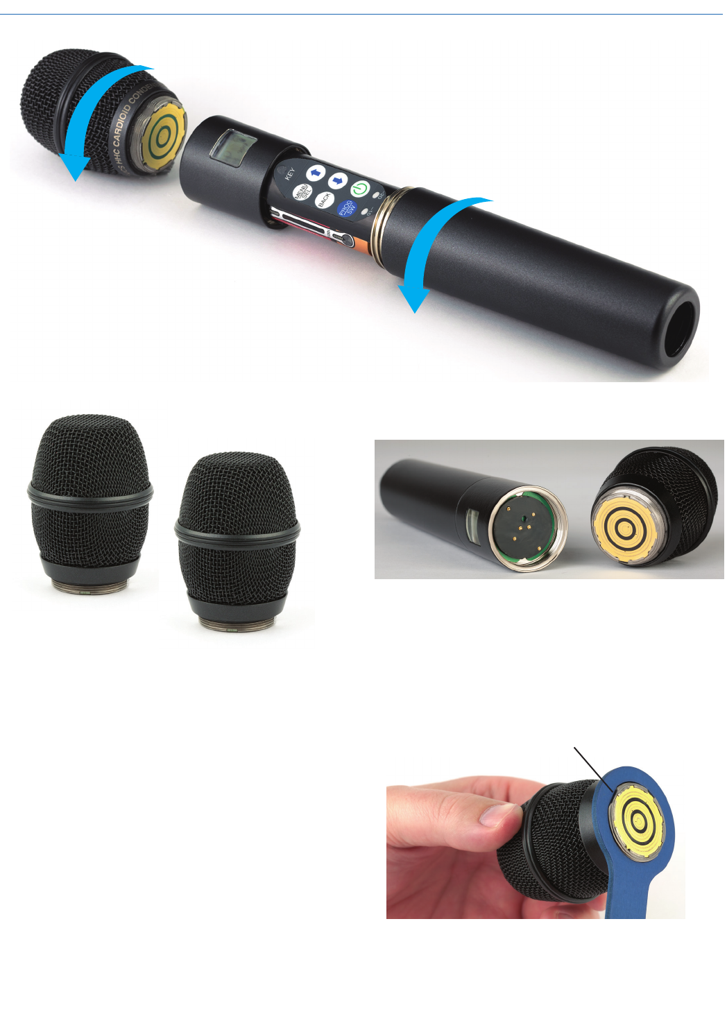
A mic capsule is
threaded onto the body
of the transmitter in the
direction shown.
Do not overtighten it.
The lower housing opens by rotating
it in the direction shown. After the
threads are disengaged, pull the
housing downward until it engages
the detent that holds it open.
The threaded interface is a 1.25”
diameter opening with 28 threads
per inch and three contact rings
Mechanical Assembly
Microphone Capsules:
Lectrosonics offers two types of capsules. The HHC is
the standard capsule and the HHVMC is the Variable
Mic Capsule which includes adjustments for Bass,
Midrange and Treble.
HHC Lectrosonics
cardioid electret
HHVMC Lectrosonics cardioid
electret with VariMic preamp
Along with these two models from Lectrosonics, a
variety of different capsules with the same thread
and electrical interface are available from the major
microphone manufacturers.
A list of compatible capsules is on the website at www.
lectrosonics.com listed on the HH transmitter page.
Do not touch the contacts between the mic capsule
and transmitter body. When necessary, the contacts
can be cleaned with a cotton swab and alcohol.
*All product names are trademarks of their respective
owners, which are in no way affiliated with Lectrosonics.
Capsule Installation
Capsules are attached with a right-hand thread.
To remove the windscreen from the mic capsule,
line up the blue wrench (included with the capsule
head) with the flat notches on the lower threaded area
of the mic capsule.
Align flats on the wrench with flats on the capsule.
Digital Hand Held Transmitter
Rio Rancho, NM 5
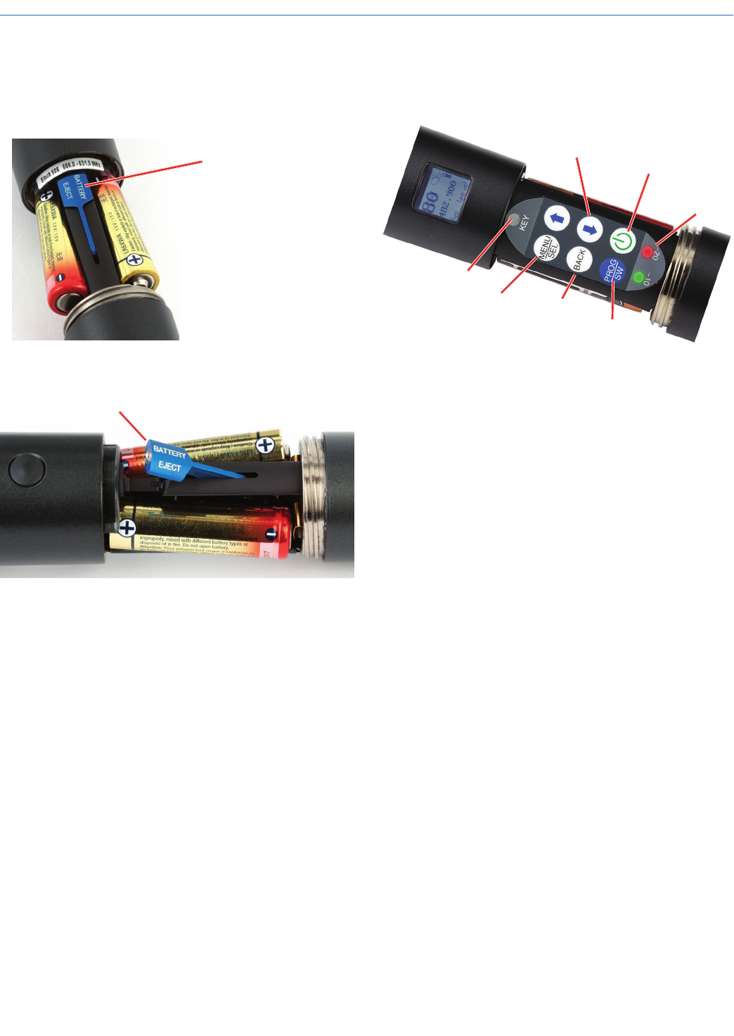
Battery Installation
To insert batteries, close the eject lever and insert the
upper contacts first (closest to the mic capsule). Polar-
ity is marked on the label in the bottom of the battery
compartment.
Close
eject lever
to install
batteries
To remove the batteries, pull the eject lever outward.
The battery tips will move outward, making them
easier to grasp.
Pull eject lever outward to release batteries from contacts
The contacts are very tight to prevent the batteries
from “rattling” as the transmitter is being handled.
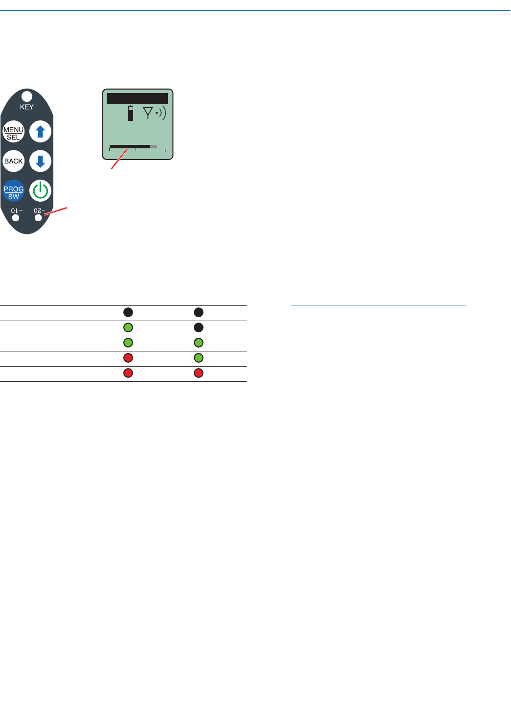
Control Panel
Six membrane switches on the control panel are used
to set up the transmitter by navigating the menus on
the LCD and selecting the desired values.
Power Button
Side Button
Setup Switch
Modulation
LEDs
Previous
Screen
UP/DOWN Buttons for
Menu Item Selection
Enter Menu and
Select Item
IR Sync Port
DHu
LECTROSONICS, INC.
6
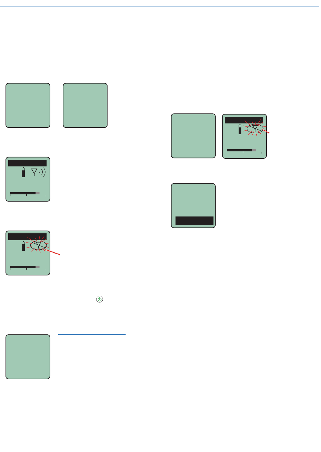
Standby Mode
A brief push of the Power Button turns the unit on and
places it into a “standby” mode (not transmitting). This
allows the transmitter to be set up without the risk of
creating interference for other wireless systems that
are operating in the vicinity.
A notice will appear briefly confirming that the RF out-
put of the transmitter is turned off, followed by the Main
Window. The antenna symbol will blink as a reminder
that the RF output is turned off.
DHu
545.400
-40 -20 0
Symbol blinks
when RF output
is turned OFF
Rf
Off
Power Menu
Resume
Pwr Off
Rf On?
Backlit
When the transmitter is turned on, a
brief push of the Power Button will
reveal a menu allowing you to
choose between Resume, Pwr Off,
Rf On?, Backlit and About.
Use the UP/DOWN buttons to select
one of the menu items, then press
the MENU/SEL button to confirm.
• Resume: Continue operating in the same condi-
tion as before.
• Pwr Off: Turns off the transmitter.
• Rf On?: Begin transmitting the RF signal, enters
another screen prompting a Yes or No answer.
• Backlit: The LCD includes a backlight that illu-
minates the display for easier viewing. It is set to
come on when any button on the control panel is
pressed, then stay on for either 30 seconds or 5
minutes, or to stay on all the time.
• About: Displays the model and firmware versions
of the microcontroller and FPGA.
The unit can also be turned off from any menu or
screen on the LCD by holding the power button in for
the duration of the countdown.
Setup and Adjustments
Powering On
Press and hold the Power Button for several seconds
until a countdown on the LCD is completed. The
countdown from 1 through 3 will appear on the LCD,
followed by a display of the model, firmware version,
frequency band and compatibility mode.
DHu
V1.01
Hold
for
Rf On
...3
When you release the button, the unit will be opera-
tional with the RF output turned ON and the Main
Window displayed.
DHu
545.400
-40 -20 0
The Main Window
RF output ON
If you release the button before the countdown is com-
plete, the unit will turn on in the Standby mode with the
RF output turned OFF and the antenna icon will blink.
DHu
545.400
-40 -20 0
The Main Window
RF output OFF
Antenna icon
blinks
Powering Off
Press and hold the Power Button (or the program-
mable button if it is configured for power on/off) for
several seconds and observe the LCD countdown
progress from 3 to 1. The power will then be turned off.
This can be done from any menu or screen.
Powering
O . . .
1
NOTE: If the Power Button
is released before the
countdown is completed, the
unit will remain turned on
and the LCD will return to the
same screen or menu that
was displayed previously.
Digital Hand Held Transmitter
Rio Rancho, NM 7
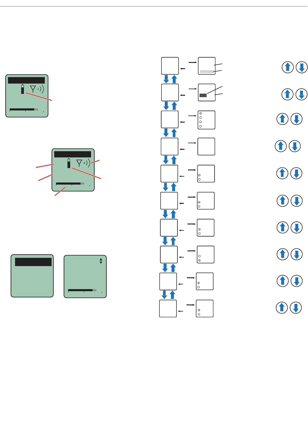
Menu Map
The menu is simple and intuitive. A summary of the
available settings is shown here, and details of the set-
tings are on the following pages.
SEL
BACK
Freq.
Select option with arrow buttons
Use arrow buttons
to select value
22
Gain SEL
BACK
Gain
Level meter at bottom of screen
Freq.
470.675
Press MENU/SEL to highlight MHz or kHz
SEL
BACK
ProgSw
Power
Cough
Mute
(none)
SEL
BACK
Rolloff
Rolloff
50 Hz Select value with arrow buttons
SEL
BACK
Phase Normal
Invert
Phase
SEL
BACK
BatType Alk.
Lith.
BatType
Select value with arrow buttons
Select option with arrow buttons
Select option with arrow buttons
SEL
BACK
BatTime
Bat 5:41
Reset?
No
Yes
Select option with arrow buttons
SEL
BACK
Default
Default
Settings
No
Yes
Select option with arrow buttons
SEL
BACK
WipeKey
No
Yes
WipeKey?
Select option with arrow buttons
SEL
BACK
TxPower
25 mW
50 mW
Select option with arrow buttons
TxPower
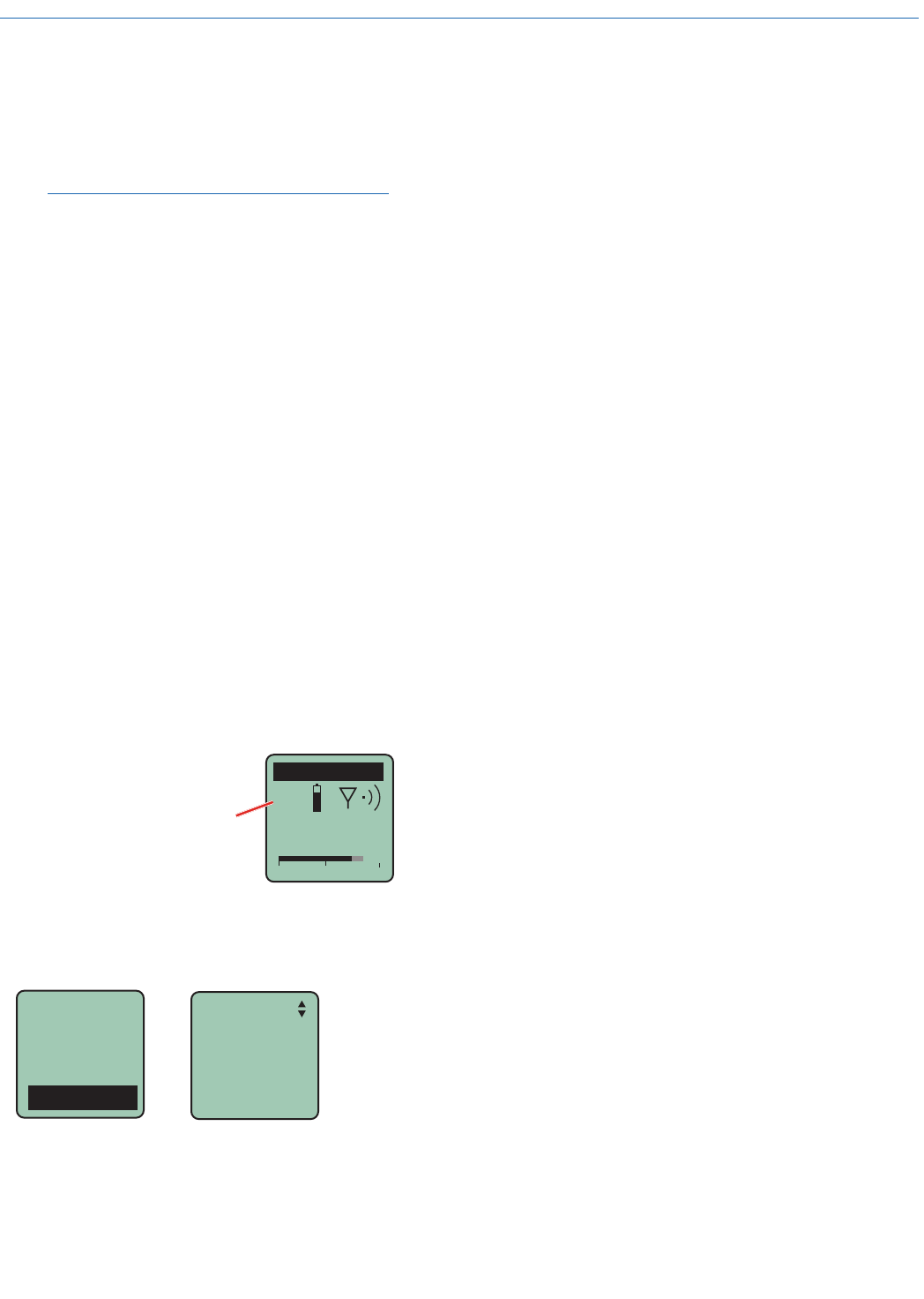
Battery Condition
An icon on the Main Window indicates the remaining
power of the transmitter batteries. This battery gauge
is most accurate with the typical voltage drop across
the life of alkaline batteries.
Battery Gauge
DHu
545.400
-40 -20 0
Navigating Menus and Screens
The Main Window displays the following information:
DHu
545.400
-40 -20 0
MUTE
Icon indicates
whether RF output
is turned on or off
Battery condition
Operating
frequency in MHz
Audio level
Function of the
programmable
switch
1) Press the MENU/SEL button to enter the setup
menu. Use the UP/DOWN buttons to highlight the
menu item.
2) Press the MENU/SEL button to enter the setup
screen for that item. Use the UP/DOWN buttons
to select the desired value or mode.
Gain
Freq.
ProgSw
Rolloff
-40 -20 0
Gain
25
3) Press the MENU/SEL button to save this setting
and return to the previous screen.
4) Press the BACK button to return to the Main
Window.
DHu
LECTROSONICS, INC.
8
Gain
This setting is very important since it will affect the dy-
namic range that the wireless system will deliver. Gain
must be set according to the individual voice, the mic
capsule in use and the handling technique of the user.
LEDs and a bar type indicator in the LCD facilitate ac-
curate gain adjustment.
IMPORTANT: See Input Gain Adjustment on the
next page for details.
Freq.
The operating frequency is normally determined using
the scanning function in the receiver or with coordina-
tion software. The frequency is shown on the trans-
mitter LCD display in MHz, and is set to match the
receiver. Press the MENU/SEL button repeatedly to
toggle back and forth between MHz and kHz. Adjust-
ment is made in 25 kHz increments.
ProgSw
The Programmable Switch on the side of the housing
can be set to provide several functions, or it can be
bypassed.
• Power: Turns the unit on and off. Press and hold
until the countdown is completed to turn the unit
off. A brief press will turn the unit on with the RF
output turned on.
• Cough: Enables a brief muting of the audio while
the button is held in. Audio is turned back on as
soon as the button is released.
• Mute: Turns the audio off and it remains muted
until the button is pressed again.
• (none): Disables the button functions
DHu
545.400
-40 -20 0
MUTE
MUTE will be displayed in the
Main Window when Cough
or Mute is enabled on the
programmable switch
Rolloff
A low frequency roll-off filter can be set for a -3dB point
at 35, 50, 70, 100, 120 or 150 Hz.
Gain
Freq.
ProgSw
Rolloff
Rolloff
70 Hz
The roll-off frequency is normally adjusted by ear to
suit personal preferences.
Phase
The phase (polarity) of the audio can be inverted to
match other microphone capsules as needed. This is
normally used when “comb filtering” is heard. Comb fil-
tering is an odd sounding distortion heard when two or
more microphones are mixed with different polarities.
Switch the transmitter setting back and forth between
Normal and Invert and listen to the audio to determine
which one is the better setting.
BatType
This sets the battery monitoring for Alkaline or Lithium
batteries.
BatTime
Accumulated operating time (runtime) can be tracked
in the transmitter. The total runtime appears on the
BatTime setup screen, displayed in (hrs):(min). The
runtime is kept during battery changes, and must be
reset manually in the BatTime setup screen.
TxPower
Output power can be set to 25mW or 50mW as
needed for the application.
Default
The default setting simply returns the transmitter back
to the factory settings.
WipeKey
Selecting Yes on this setup screen erases the stored
encryption key in the transmitter.
Digital Hand Held Transmitter
Rio Rancho, NM 9
Input Gain Adjustment
The two bicolor Modulation LEDs (located at the bot-
tom of the control panel) provide a visual indication of
the audio signal level entering the transmitter.
DHu
545.400
-40 -20 0
The audio level is shown by LEDs
and a bar type indicator on the LCD.
The gain should be set so that
the -20 LED just turns red on the
loudest peak (the onset of limiting).
The LEDs are marked for viewing when the mic cap-
sule is held up to your mouth. They will glow either red
or green to indicate modulation levels as shown in the
following table.
Signal Level -20 LED -10 LED
Less than -20 dB Off Off
-20 dB to -10 dB Green Off
-10 dB to +0 dB Green Green
+0 dB to +10 dB Red Green
Greater than +10 dB Red Red
It is best to go through the following procedure with the
transmitter in the “standby” mode so that no audio will
enter the sound system, which could cause feedback.
1) With fresh batteries in the transmitter, power the
unit on into “standby” (no transmission) mode.
2) Press the MENU/SEL button once to enter the
setup menu. Use the UP/DOWN buttons to select
Gain. Press the MENU/SEL button again to enter
the setup screen.
3) Hold the microphone the way it will be used in
actual operation.
4) Speak or sing at the same voice level that will
actually be used during the program, while ob-
serving the modulation LEDs. Use the UP/DOWN
buttons to adjust the gain until the –20 dB LED
starts to flicker red and the –10 dB glows green.
5) Once the audio gain has been set, the RF output
can be turned on and the audio sent through the
sound system for overall level adjustments, moni-
tor settings, etc.
NOTE: Full modulation is achieved when the
-20 LED first turns red. 30 dB of clean limiting is
available above this point.
DHu
LECTROSONICS, INC.
10
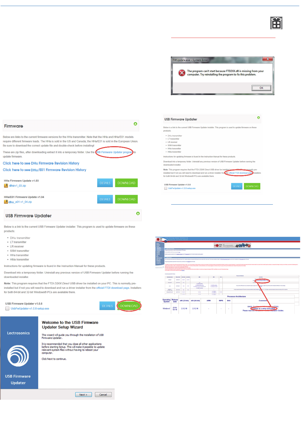
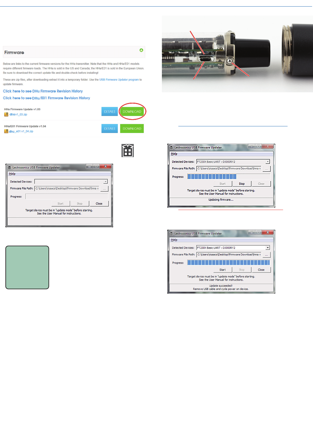
Firmware Update
Updating the firmware is a simple matter of download-
ing a utility program and file from the website and run-
ning the program on a Windows operating system
with the transmitter connected to a computer via the
USB port.
Go to www.lectrosonics.com/US. In the top menu,
hover the mouse over Support, and click on Wireless
Support. On the right-hand-side Wireless Support
Menu, choose Wireless Downloads. Choose your prod-
uct (DHu), then choose Firmware.
Step 1:
Begin by downloading the USB Firmware Updater
Program.
Step 2:
Next, test the Updater by opening the icon: If the
driver opens automatically, proceed to Step 3.
WARNING: If you receive the following error, the
Updater is not installed on your system. Follow the
TROUBLESHOOTING steps to fix the error.
TROUBLESHOOTING:
If you
receive the
FTDI D2XX
error shown
above,
download
and install
the driver by
clicking on
this link.
Then click here to download.
NOTE: This website, http://www.ftdichip.com/
Drivers/D2XX.htm, is not associated with
Lectrosonics.com. It is a third party site used
only for D2XX drivers currently available for
Lectrosonics’ devices’ upgrades.
Digital Hand Held Transmitter
Rio Rancho, NM 11
Step 3:
Refer to Step 1 to return to Firmware web page. Down-
load Firmware Update and save to a local file on your
PC for easy locating when updating.
Step 4:
Open Lectrosonics USB Firmware Updater.
Step 5:
UPDAT E
Put the transmitter in UPDATE
mode by simultaneously holding
down the BACK and UP arrow
buttons on the transmitter control
panel while powering it up.
Step 6:
Using a microUSB cable, connect the transmitter to
your PC.
Remove the lower housing of the transmitter by un-
screwing it from the housing attached to the capsule
and pulling it straight off the body of the transmitter to
expose the circuitry. Spring-loaded ball detents provide
a “stop” with only the control panel exposed. Continue
to pull the lower housing farther to remove it. Simply
push the lower housing back onto the transmitter body
to re-install it.
The USB port on the transmitter requires a micro-B
male plug on the connecting cable. The other end of
the cable would normally be a USB A-Type male con-
nector to fit the most common type of USB jack used
on computers.
USB Port
Opening in clear
plastic sleeve
Spring-loaded balls
engage detents in housing
Step 7:
In Lectrosonics USB Firmware Updater, choose the
detected device, browse to local Firmware File and
click Start.
NOTE: It may take up to a minute or so for the
Updater to recognize the transmitter.
WARNING: Do not disrupt the microUSB cable
during updating.
The Updater alerts with progress and completion.
Step 8:
Once the Updater has completed, turn off the trans-
mitter, then turn it back on while viewing the LCD to
verify that the firmware version on the transmitter LCD
matches the firmware version shown on the web site.
DHu
LECTROSONICS, INC.
12
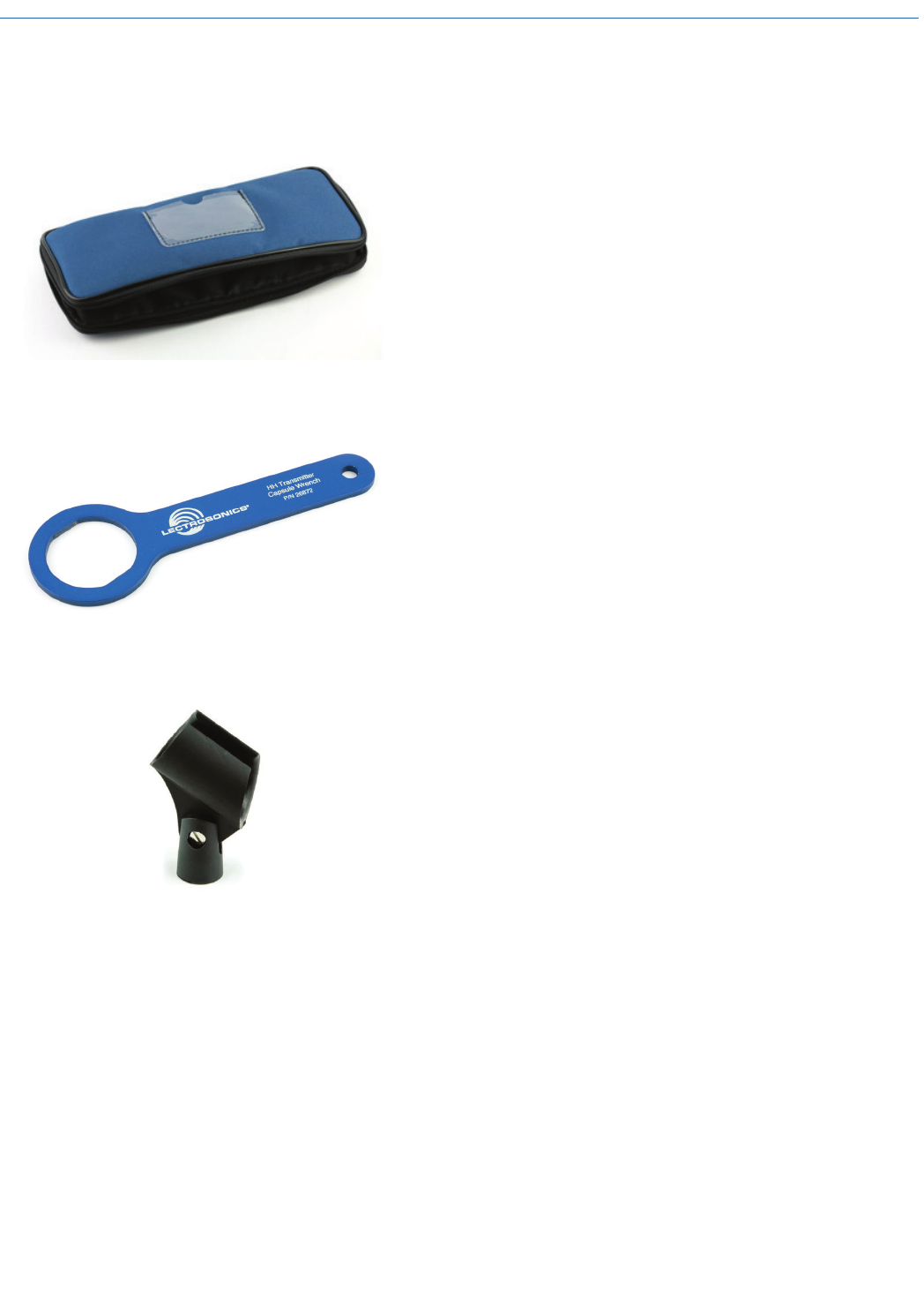
Parts and Accessories
#CCHH - Zippered Pouch
Padded zipper pouch for handheld transmitter
#26872 Mic Capsule Wrench
Custom wrench for removing windscreen from mic
capsule
#13585 Mic Clip
Screw on mic clip for standard mic stands with 5/8”-27
thread

Digital Hand Held Transmitter
Rio Rancho, NM 13
Troubleshooting
SYMPTOM POSSIBLE CAUSE
TRANSMITTER WILL NOT POWER ON 1) Batteries are inserted backwards.
2) Batteries are dead, or too low to be used.
DHu MODULATION LEDs OFF 1) Audio Gain set too low.
2) Battery is inserted backwards. Check LCD for power indication.
3) Mic capsule is damaged or malfunctioning. Contact the factory
for repair.
DHu MODULATION LEDs GOOD BUT NO SOUND
1) Talkback function is engaged (release multi-function button).
See p. 11.
2) Receiver on wrong frequency or wrong band.
3) Receiver connected incorrectly to sound system.
4) Transmitter in standby mode.
RECEIVER RF INDICATOR OFF 1) Transmitter not turned on.
2) Transmitter is in “standby” (non-transmitting) mode. Check the
LCD for the antenna/transmission icon status.
3) Batteries are dead or installed backwards.
4) Receiver antenna missing, defective or improperly positioned.
5) Transmitter and receiver not on same frequency band.
Check labels on transmitter and receiver to be sure they are
operating on the same frequency band.
6) Make sure the transmitter and receiver frequency settings are in
agreement.
7) Operating range is too great.
8) Receiver antenna missing, incorrect frequency or disconnected.
NO SOUND BUT RECEIVER AUDIO LEVEL METER INDICATES SOUND
1) Receiver audio is muted. (Unmute receiver.)
2) Receiver audio output levels set too low.
3) Receiver audio output is disconnected or cable defective
or mis-wired.
4) Sound system or recorder input level is turned down.
DISTORTED SOUND 1) Transmitter Audio Gain set too high. Speak or sing into the
transmitter and check the Audio Level LEDs, Audio Level bar
graph in the transmitter
LCD and corresponding indicators on the receiver.
2) Receiver output level may be too high for the sound system or
recorder input.
3) Excessive wind noise or “breath pops.” Microphone may require
an additional wind screen.
4) Transmitter frequency setting is not correct.
5) Mic capsule damaged or defective
HISS AND NOISE -- AUDIBLE DROPOUTS 1) Transmitter Audio Gain set too low. See page 9 for proper audio
gain setting.
2) Receiver antenna missing, defective or obstructed.
3) Operating range too great.
4) Interference may be present. Turn transmitter off and observe the
RF level indicator on the receiver. Change frequency if necessary.
5) Return attenuator control back to default setting of “F”, then
readjust audio gain per instructions on page 9
EXCESSIVE FEEDBACK 1) Transmitter Audio Gain set too high. Check level adjustment,
reduce receiver output level, or both.
2) Microphone too close to speaker system.
3) Move microphone closer to the user’s mouth and lower the
sound system volume.

DHu
LECTROSONICS, INC.
14
Specifications
Frequency range: 470.100 - 607.975 MHz
Frequency selection steps: 25 kHz
RF Power output: Selectable; 25 or 50 mW
Frequency stability: ± 0.002%
Digital Modulation: 8 psk
Spurious radiation: Compliant with ETSI EN 300 422-1 v1.4.2
Operating temperature range: -20° C to +50° C
Input compressor: Dual envelope compressor, >30 dB range
Gain control range: 45 dB; semi-log menu-driven control; 1 dB steps
Modulation indicators: Dual bicolor LEDs indicate modulation
of -20, -10, 0 and +10 dB referenced to full
modulation and LCD bar-type indicator
Frequency response 40 Hz to 20 kHz (+/- 1dB)
Low frequency roll-off: Selectable -3 dB @35, 50, 70, 100, 120, 150 Hz
Controls:
External: Programmable mute/power button
Under battery cover: Power, menu/select, back, programmable switch
and up/down arrow buttons for menu selection
and settings
Battery: 2x AA with polarity protection and battery
ejector
Battery life: At 50 mW: 5 hours (Duracell Procell)
(The DHu transmits battery status to
Lectrosonics receivers.)
Capsule Interface: 1.25” opening and 28 thread pitch
Power available: 5V, 25 mA max
Input impedance: 1000 Ohms
Weight: 12.1 oz. with batteries and HHC capsule
Dimensions: 9.5” long x 1.97” diameter at largest point
Emission Designator: 200KG1E
Specifications subject to change without notice.
FCC Compliance:
This device complies with FCC radiation exposure
limits as set forth for an uncontrolled environment.
This device should be installed and operated so
that its antenna(s) are not co-located or operating
in conjunction with any other antenna or transmitter.
ISEDC Notices:
Per RSS-210
This device operates on a no-protection no-in-
terference basis. Should the user seek to obtain
protection from other radio services operating in
the same TV bands, a radio licence is required.
Please consult Industry Canada’s document
CPC-2-1-28, Optional Licensing for Low-Power
Radio Apparatus in the TV Bands, for details.
Ce dispositif fonctionne selon un régime de non-
brouillage et de non-protection. Si l’utilisateur
devait chercher à obtenir une certaine protection
contre d’autres services radio fonctionnant dans
les mêmes bandes de télévision, une licence
radio serait requise. Pour en savoir plus, veuillez
consulter le document CPC-2-1-28 d’Industrie
Canada intitulé, Délivrance de licences sur une
base volontaire pour les appareils radio de faible
puissance exempts de licence et exploités dans
les bandes de télévision.
Per RSS-Gen
This device complies with Industry Canada’s
license-exempt RSSs. Operation is subject to the
following two conditions:
1) This device may not cause interference
2) This device must accept any interference, in-
cluding interference that may cause undesired
operation of the device.
Le présent appareil est conforme aux CNR
d’Industrie Canada applicables aux appareils
radio ex¬empts de licence. L’exploitation est
autorisée aux deux conditions suivantes :
1) l’appareil ne doit pas produire de brouillage;
2) l’appareil doit accepter tout brouillage ra-
dioélectrique subi, même si le brouillage
est susceptible d’en compromettre le fonc-
tionnement.
ISED Notice to the End User:
The normal condition of using this device is to keep
the hand at least 20mm away from the base of the
microphone.
La condition normale d’utilisation de cet appareil
est de garder la main à au moins 20 mm de la
base du microphone.
FCC Notice to the End User:
The normal condition of using this device is to keep
the hand at least 20mm away from the base of the
microphone.

Digital Hand Held Transmitter
Rio Rancho, NM 15
Service and Repair
If your system malfunctions, you should attempt to correct or isolate the trouble before concluding that the equip-
ment needs repair. Make sure you have followed the setup procedure and operating instructions. Check the inter-
connecting cables and then go through the Troubleshooting section in this manual.
We strongly recommend that you do not try to repair the equipment yourself and do not have the local repair shop
attempt anything other than the simplest repair. If the repair is more complicated than a broken wire or loose con-
nection, send the unit to the factory for repair and service. Don’t attempt to adjust any controls inside the units.
Once set at the factory, the various controls and trimmers do not drift with age or vibration and never require read-
justment. There are no adjustments inside that will make a malfunctioning unit start working.
LECTROSONICS’ Service Department is equipped and staffed to quickly repair your equipment. In-warranty repairs
are made at no charge in accordance with the terms of the warranty. Out-of-warranty repairs are charged at a mod-
est flat rate plus parts and shipping. Since it takes almost as much time and effort to determine what is wrong as it
does to make the repair, there is a charge for an exact quotation. We will be happy to quote approximate charges by
phone for out-of-warranty repairs.
Returning Units for Repair
For timely service, please follow the steps below:
A. DO NOT return equipment to the factory for repair without first contacting us by letter or by phone. We need to
know the nature of the problem, the model number and the serial number of the equipment. We also need a
phone number where you can be reached 8 A.M. to 4 P.M. (U.S. Mountain Standard Time).
B. After receiving your request, we will issue you a return authorization number (R.A.). This number will help
speed your repair through our receiving and repair departments. The return authorization number must be
clearly shown on the outside of the shipping container.
C. Pack the equipment carefully and ship to us, shipping costs prepaid. If necessary, we can provide you with the
proper packing materials. UPS is usually the best way to ship the units. Heavy units should be “double-boxed”
for safe transport.
D. We also strongly recommend that you insure the equipment, since we cannot be responsible for loss of or
damage to equipment that you ship. Of course, we insure the equipment when we ship it back to you.
Mailing address: Shipping address: Telephone:
Lectrosonics, Inc. Lectrosonics, Inc. (505) 892-4501
PO Box 15900 581 Laser Rd. (800) 821-1121 Toll-free
Rio Rancho, NM 87174 Rio Rancho, NM 87124 (505) 892-6243 Fax
USA USA
Web: E-mail:
www.lectrosonics.com sales@lectrosonics.com
Lectrosonics Canada:
Mailing Address: Telephone: E-mail:
720 Spadina Avenue, (416) 596-2202 Sales: colinb@lectrosonics.com
Suite 600 (877) 753-2876 Toll-free Service: joeb@lectrosonics.com
Toronto, Ontario M5S 2T9 (877-7LECTRO)
(416) 596-6648 Fax

16
2 November 2017
581 Laser Road NE • Rio Rancho, NM 87124 USA • www.lectrosonics.com
+1(505) 892-4501 • fax +1(505) 892-6243 • (800) 821-1121 US and Canada • sales@lectrosonics.com
LIMITED ONE YEAR WARRANTY
The equipment is warranted for one year from date of purchase against defects in
materials or workmanship provided it was purchased from an authorized dealer. This
warranty does not cover equipment which has been abused or damaged by careless
handling or shipping. This warranty does not apply to used or demonstrator equipment.
Should any defect develop, Lectrosonics, Inc. will, at our option, repair or replace any
defective parts without charge for either parts or labor. If Lectrosonics, Inc. cannot
correct the defect in your equipment, it will be replaced at no charge with a similar new
item. Lectrosonics, Inc. will pay for the cost of returning your equipment to you.
This warranty applies only to items returned to Lectrosonics, Inc. or an authorized
dealer, shipping costs prepaid, within one year from the date of purchase.
This Limited Warranty is governed by the laws of the State of New Mexico. It states the
entire liablility of Lectrosonics Inc. and the entire remedy of the purchaser for any
breach of warranty as outlined above. NEITHER LECTROSONICS, INC. NOR
ANYONE INVOLVED IN THE PRODUCTION OR DELIVERY OF THE EQUIPMENT
SHALL BE LIABLE FOR ANY INDIRECT, SPECIAL, PUNITIVE, CONSEQUENTIAL,
OR INCIDENTAL DAMAGES ARISING OUT OF THE USE OR INABILITY TO USE
THIS EQUIPMENT EVEN IF LECTROSONICS, INC. HAS BEEN ADVISED OF THE
POSSIBILITY OF SUCH DAMAGES. IN NO EVENT SHALL THE LIABILITY OF
LECTROSONICS, INC. EXCEED THE PURCHASE PRICE OF ANY DEFECTIVE
EQUIPMENT.
This warranty gives you specific legal rights. You may have additional legal rights which
vary from state to state.