Leica Biosystems Nussloch SPECTRAST Multistainer User Manual
Leica Biosystems Nussloch GmbH Multistainer
Contents
User Manual
Instructions for Use
Leica HistoCore SPECTRA ST
Staining machine
Leica HistoCore SPECTRA ST V 0.5 RevC, English 08 /2014
Order No.: 14 0512 80100 RevC
Always keep this manual with the instrument.
Read carefully before working with the instrument.
V 0.5 RevC - 08/2014
DRAFT
201
4-
08
-
21
DRAFT
201
4-
08
-
21

1
Leica HistoCore SPECTRA ST
The information, numerical data, notes and value
judgments contained in this manual represent the
current state of scientific knowledge and state-of-
the-art technology as we understand it following
thorough investigation in this field.
We are under no obligation to update the pres-
ent Instructions for Use periodically and on an
ongoing basis according to the latest technical
developments, nor to provide our customers with
additional copies, updates etc. of these Instruc-
tions for Use.
To the extent permitted in accordance with the
national legal system as applicable in each indi-
vidual case, we shall not be held liable for errone-
ous statements, drawings, technical illustrations
etc. contained in these Instructions for Use. In
particular, no liability whatsoever is accepted for
any financial loss or other consequential damage
caused by or related to compliance with state-
ments or other information in these instructions
for use.
Statements, drawings, illustrations and other
information regarding the contents or technical
details of the present Instructions for Use are not
to be considered warranted characteristics of
our products. These are determined only by the
contract provisions agreed between ourselves
and our customers.
Leica reserves the right to change technical spec-
ifications as well as manufacturing processes
without prior notice. Only in this way is it pos-
sible to continuously improve the technology and
manufacturing techniques used in our products.
This document is protected under copyright laws.
All copyrights to this documentation are held by
Leica Biosystems Nussloch GmbH.
Any reproduction of text and illustrations (or of
any parts thereof) by means of print, photocopy,
microfiche, web cam or other methods – includ-
ing any electronic systems and media – requires
express prior permission in writing by Leica Bio-
systems Nussloch GmbH.
For the instrument serial number and year of
manufacture, please refer to the nameplate on
the back of the instrument.
© Leica Biosystems Nussloch GmbH
NOTE
Leica Biosystems Nussloch GmbH
Heidelberger Str. 17 - 19
D-69226 Nussloch
Germany
Phone: +49 6224 143-0
Fax: +49 6224 143-268
Internet: http://www.LeicaBiosystems.com
DRAFT
DRAFT
DRAFT
NO
TE
NOTE
2014-08-21
p
p
entific knowled
g
e and state-of
-entific knowledge and sta
y
as we understand it following
as we understand it following
ation in this field.ation in this f
gg
gg
details of the
p
resent Ins
tdetails of the present Inst
to be considered warra
no be considered warran
our products. These areour products. These are

2Instructions for Use V 0.5 RevC - 08/2014
Table of Contents
1. Important Information ................................................................................................................. 5
1.1 Instrument Name .......................................................................................................................... 5
1.2 Symbols and their meanings....................................................................................................... 5
1.3 Instrument type ........................................................................................................................... 13
1.4 Qualification of personnel ......................................................................................................... 13
1.5 Intended use of instrument ....................................................................................................... 13
2. Safety ......................................................................................................................................... 14
2.1 Safety notes ................................................................................................................................. 14
2.2 Warnings ...................................................................................................................................... 16
2.3 Safety features on the instrument ........................................................................................... 20
3. Instrument Components and Specifications ......................................................................... 21
3.1 Standard delivery—packing list............................................................................................... 21
3.2 Technical Data ............................................................................................................................ 22
3.3 Overview ...................................................................................................................................... 24
4. Installation and Starting Up ..................................................................................................... 27
4.1 Installation site requirements ................................................................................................... 27
4.2 Running water connection ........................................................................................................ 28
4.2.1 Joint connection of all 6 rinsing water stations .................................................................... 29
4.2.2 Combined connection 4+2 rinsing water stations ................................................................. 30
4.2.3 Wastewater connection ............................................................................................................ 31
4.3 Electrical Connection ................................................................................................................. 32
4.3.1 Using an external uninterruptible power supply (UPS) ........................................................ 33
4.4 Exhaust air connection .............................................................................................................. 33
4.5 Switching the instrument on and off ....................................................................................... 34
5. Operation ..................................................................................................................................... 35
5.1 User interface – overview ......................................................................................................... 35
5.2 Status bar elements ................................................................................................................... 36
5.3 Process status display ............................................................................................................... 37
5.4 Displaying the drawers .............................................................................................................. 39
5.5 Main menu-overview ................................................................................................................. 40
5.5.1 The keyboard ............................................................................................................................... 41
5.6 User settings ................................................................................................................................ 43
5.7 Basic settings .............................................................................................................................. 45
5.7.1 Language settings ...................................................................................................................... 46
5.7.2 Country-specific settings .......................................................................................................... 46
5.7.3 Date and time .............................................................................................................................. 47
DRAFT
DRAFT
2014-08-21
ent
Name
nt Name
.
........................................................................................
.........................................................................................
and their meaning
sand their meanin
.
.....................................................................
....................................................................
e
nt type
nt type
.
...........................................................................................
............................................................................................
ation of personnelation of personnel

3
Leica HistoCore SPECTRA ST
Table of Contents
5.7.4 Alarm and signal tones .............................................................................................................. 47
5.7.5 Setting the oven .......................................................................................................................... 49
5.7.6 Movement speed - up/down movement (agitation) .............................................................. 50
5.7.7 Data management ...................................................................................................................... 51
5.7.8 Service access ............................................................................................................................ 54
5.7.9 Event view .................................................................................................................................... 54
5.7.10 Network settings ......................................................................................................................... 55
5.8 Reagent list .................................................................................................................................. 56
5.8.1 Define heated reagent (optional) ............................................................................................. 57
5.8.2 Creating a new reagent ............................................................................................................. 58
5.8.3 Process classes .......................................................................................................................... 60
5.9 Staining program ........................................................................................................................ 63
5.9.1 Staining program - general settings ........................................................................................ 64
5.9.2 Leica staining programs (preinstalled) ...................................................................................65
5.9.3 Adapting the Leica H&E staining program ............................................................................. 66
5.9.4 User-defined staining programs ............................................................................................. 66
5.9.5 Creating a new staining program............................................................................................. 67
5.9.6 Inserting a new program step (continued) ............................................................................. 69
5.9.7 Resorting a program step .......................................................................................................... 70
5.9.8 Prioritizing programs .................................................................................................................. 71
5.9.9 Creating a bathlayout ................................................................................................................. 72
5.9.10 Adjusting a bathlayout ............................................................................................................... 75
6. Daily Instrument Setup ........................................................................................................... 78
6.1 Preparing the instrument for daily setup ................................................................................ 78
6.2. Daily setup of the instrument .................................................................................................... 79
6.2.1 Preparation and handling of reagent cuvettes ...................................................................... 79
6.2.2 Automatic fill level scan ............................................................................................................ 81
6.3 Reagent management system (RMS) ...................................................................................... 82
6.4 Station features ........................................................................................................................... 84
6.5 Prepare slide rack ...................................................................................................................... 89
6.6 The staining process .................................................................................................................. 91
6.6.1 Start the staining process ......................................................................................................... 91
6.7.2 Monitoring the staining process .............................................................................................. 93
6.7.3 Staining process completed ..................................................................................................... 94
6.7.4 Canceling the staining program ............................................................................................... 95
6.7.5 Operation as a workstation ....................................................................................................... 96
DRAFT
DRAFT
DRAFT
2014-08-21
ng
the
oven
g the oven
.....................................................................................
............................................................................
e
ment s
p
eed - u
p
/down movement (a
g
itation
)ement speed - up/down movement (agitatio
.
........................
............
management
managemen
.
................................................................................
............................................................................
ce accessce access

4Instructions for Use V 0.5 RevC - 08/2014
7. Cleaning and Maintenance ....................................................................................................98
7.1 Important notes about this instrument cleaning ................................................................... 98
7.1.1 Exterior surfaces, varnished surfaces, instrument cover.................................................... 98
7.1.2 TFT touchscreen ......................................................................................................................... 98
7.1.3 Interior and drain pan ................................................................................................................ 99
7.1.4 Transport arms ............................................................................................................................ 99
7.1.5 Reading module for specimen slides ...................................................................................... 99
7.1.6 Input and output drawers ........................................................................................................ 100
7.1.7 Dry transfer station ................................................................................................................... 100
7.1.8 Transfer station (optional) ....................................................................................................... 100
7.1.9 Reagent cuvettes, rinsing water cuvettes and heated cuvettes (optional) .................... 101
7.1.10 Rack and clip ............................................................................................................................. 102
7.1.11 Water drain ................................................................................................................................ 103
7.1.12 Water drain hose ...................................................................................................................... 104
7.1.13 Water intake filter – changing the filter cartridge .............................................................. 104
7.1.14 Replacing the active carbon filter.......................................................................................... 105
7.1.15 Cleaning the ovens ................................................................................................................... 106
7.1.16 Oven air filter ............................................................................................................................. 107
7.2 Recommended maintenance and cleaning intervals ......................................................... 108
8. Malfunctions and Troubleshooting ...................................................................................... 111
8.1 Fault remedies for instrument malfunctions ........................................................................ 111
8.2 Power failure scenario ............................................................................................................ 114
8.3 Replace main fuses .................................................................................................................. 115
9. Instrument Components and Specifications ..................................................................... 116
9.1 Optional instrument components ........................................................................................... 116
9.2 Optional Accessories ............................................................................................................... 118
10. Garantie und Service ............................................................................................................ 124
11. Decommissioning and Disposal ......................................................................................... 125
12. Decontamination Certificate (master) ............................................................................... 126
Appendix 1 ......................................................................................................................................... 128
A1 Compatible reagents ................................................................................................................ 128
Table of Contents
DRAFT
DRAFT
DRAFT
2014-08-21
nt
notes
about
this
instrument
cleaning
t notes about this instrument cleani
.
...................................
....................................
surfaces, varnished surfaces, instrument cover
surfaces, varnished surfaces, instrument c
.
....................
............
c
hscree
nhscreen
.
.........................................................................................
......................................................................................
and drain panand drain pa
5
Leica HistoCore SPECTRA ST
1. Important Information
1.2 Symbols and their meanings
Leica Biosystems GmbH assumes no liability for consequential loss or damage due to failure
to observe the following notes, particularly in relation to transportation and package handling,
and failure to observe the notes for handling the instrument carefully.
Symbol: Title of the symbol: Caution
Description: Indicates the need for the user to consult the instruc-
tions for use for important cautionary information
such as warnings and precautions that cannot, for
a variety of reasons, be presented on the medical
device itself.
Symbol: Title of the symbol: Notes
Description: This symbol indicates important information for the
user. The notes appear in a gray and are marked by
this symbol.
Symbol: Title of the symbol: Item numbers
Description: Numbers and parentheses refer to item numbers in
the illustrations.
Symbol: Title of the symbol: Function keys
Description: Function keys that must be pushed on the touch-
screen or activated in the software are shown in
BOLD.
Symbol: Title of the symbol: Leica Biosystems GmbH company logo
Description: Indicates the trademark of the company.
1.1 Instrument Name
The full name of the device is HistoCore SPECTRA ST. The device is called SPECTRA ST to en-
sure that the Instructions for Use are well legible.
DRAFT
DRAFT
DRAFT
2014-08-21
name of the device is HistoCore SPECTRA ST. The device is ca
he Instructions for Use are well legible.
2014-08-21
6Instructions for Use V 0.5 RevC - 08/2014
1. Important Information
1.2 Symbols and their meanings (continued)
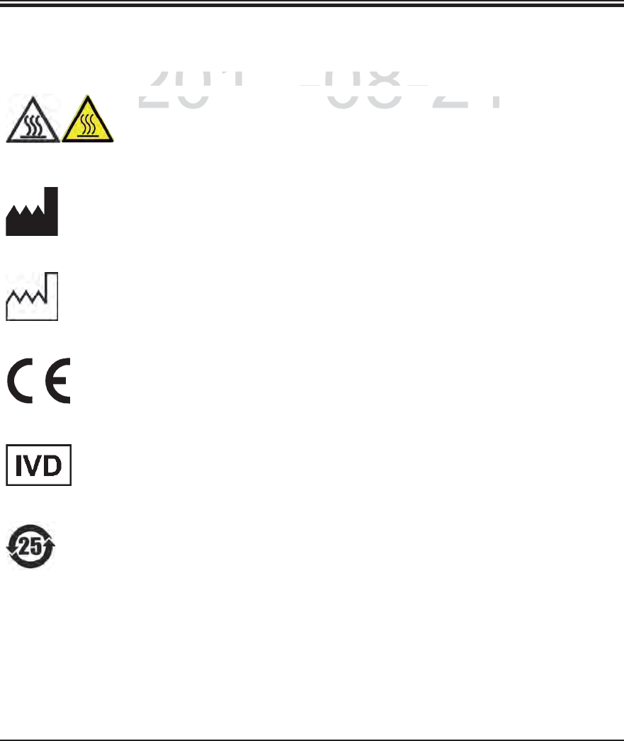
Symbol: Title of the symbol: Warning, hot surface
Description: Instrument surfaces which become hot during opera-
tion are marked with this symbol. Avoid direct contact
to prevent risk of burning.
Symbol: Title of the symbol: Manufacturer
Description: Indicates the medical device manufacturer, as de-
fined in EU Directives.
Symbol: Title of the symbol: Date of Manufacture
Description: Indicates the date when the medical device was
manufactured.
Symbol: Title of the symbol: CE Compliance
Description: The CE marking is the manufacturer's declaration
that the medical product meets the requirements of
the applicable EC directives.
Symbol: Title of the symbol: In vitro diagnostic medical device
Description: Indicates a medical device that is intended to be used
as an in vitro diagnostic medical device.
Symbol: Title of the symbol: China ROHS
Description: Environmental protection symbol of the China RoHS
directive. The number in the symbol indicates the
"Environment-friendly Use Period" of the product in
years. The symbol is used if a substance restricted
in China is used in excess of the maximum permit-
ted limit.
DRAFT
DRAFT
DRAFT
2014-08-21
Title of the s
y
mbol:
tle of the symb
Warnin
g
, hot surfac
eWarning, hot surface
D
escr
ip
t
i
on
:Description
Instrument surfaces which beco
mument surfaces which becom
7
Leica HistoCore SPECTRA ST
1. Important Information
1.2 Symbols and their meanings (continued)
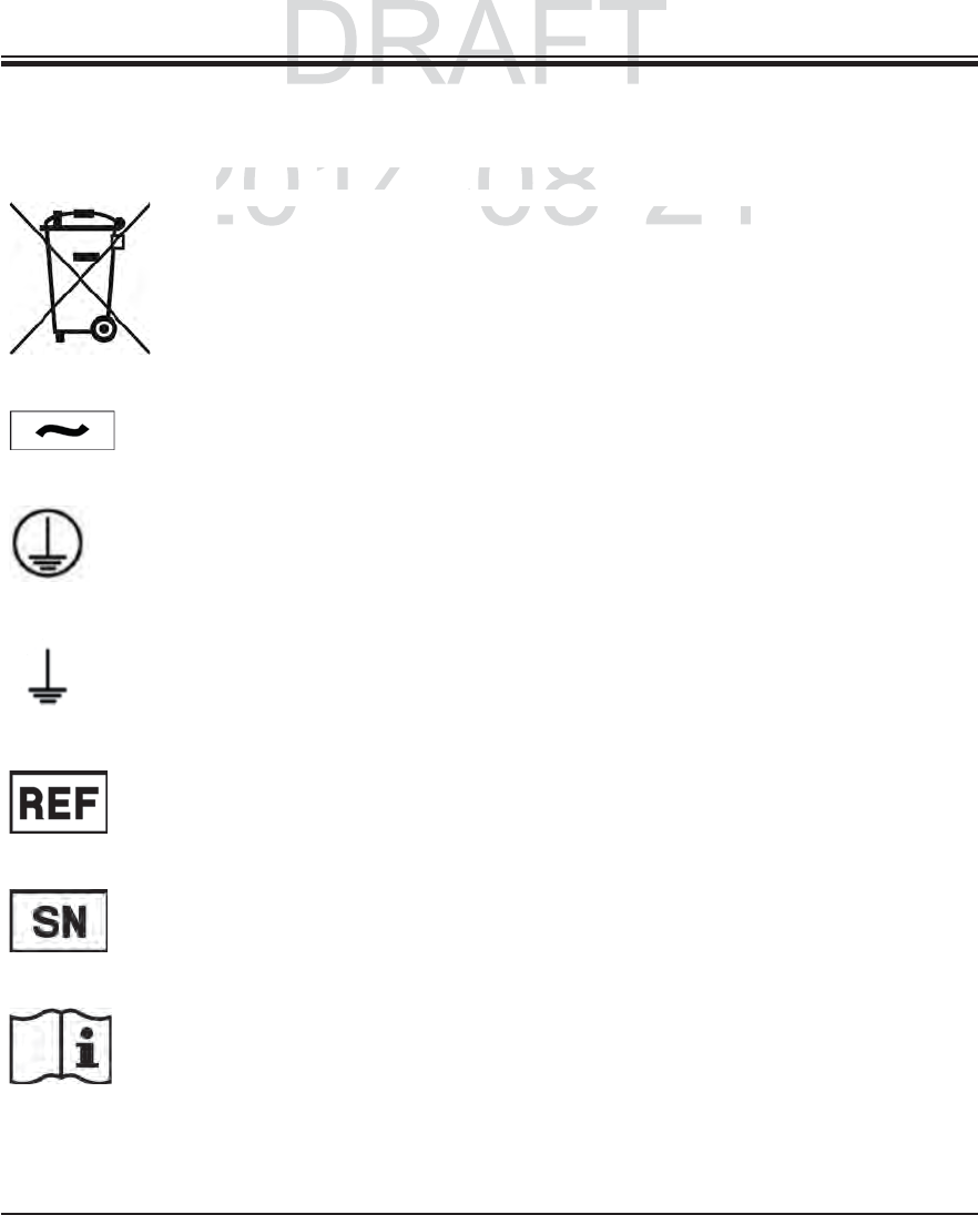
Symbol: Title of the symbol: WEEE Symbol
Description: The WEEE symbol, indicating separate collection for
WEEE - Waste of electrical and electronic equip-
ment, consists of the crossed-out wheeled bin (§ 7
ElektroG).
Symbol: Title of the symbol: Alternating current
Description:
Symbol: Title of the symbol: PE terminal
Description:
Symbol: Title of the symbol: Earth (Ground) terminal
Description:
Symbol: Title of the symbol: Article number
Description: Indicates the manufacturer's catalogue number so
that the medical device can be identified.
Symbol: Title of the symbol: Serial Number
Description: Indicates the manufacturer's serial number so that a
specific medical device can be identified.
Symbol: Title of the symbol: Consult instructions for use
Description: Indicates the need for the user to consult the instruc-
tions for use.
DRAFT
DRAFT
2014-08-21
Title of the s
y
mbol:
Title of the symbol:
WEEE Symbo
lWEEE Symbo
D
escr
ip
t
i
on
:Descript
The WEEE s
y
mbol
,
indicatin
g
he WEEE symbol, indicating s
8Instructions for Use V 0.5 RevC - 08/2014
1. Important Information
1.2 Symbols and their meanings (continued)
Symbol: Title of the symbol: ON (Power)
Description: The power supply is connected upon pushing the
power switch.
Symbol: Title of the symbol: OFF (Power)
Description: The power supply is disconnected upon pushing the
power switch.
Symbol: Title of the symbol: Caution, possibility of electronic shock
Description Instrument surfaces or areas which become ener-
gized during operation are marked with this symbol.
Therefore, direct contact is to be avoided.
Symbol: Title of the symbol: Caution: danger of crushing
Symbol: Title of the symbol: IPPC symbol
Description: The IPPC symbol includes
IPPC symbol
Country code to ISO 3166, e.g. DE for Germany
Regional identifier, e.g. HE for Hesse
Registration number, unique number beginning
with 49.
Treatment method, e.g. HT (heat treatment)
Symbol: Title of the symbol: Fragile, handle with care
Description: Indicates a medical device that can be broken or
damaged if not handled carefully.
DRAFT
DRAFT
DRAFT
2014-08-21
Title of the s
y
mbol:
tle of the symb
ON
(
Power
)(Power)
D
escr
ip
t
i
on:
Description
Th
e
p
ower su
pply
i
s connecte
dpower supply is connected
9
Leica HistoCore SPECTRA ST
1. Important Information
1.2 Symbols and their meanings (continued)
Symbol: Title of the symbol: Keep dry
Description: Indicates a medical device that needs to be protected
from moisture.
Symbol: Title of the symbol: Do not stack
Description: Stacking of the transport package is not allowed and
no load should be placed on the transport package.
Symbol: Title of the symbol: This way up
Description: Indicates correct upright position of the transport
package.
Symbol: Title of the symbol: Temperature limit for transport
Description: Indicates the temperature limits for transport to
which the medical device can be safely exposed.
Symbol: Title of the symbol: Temperature limit for storage
Description: Indicates the temperature limits for storage to which
the medical device can be safely exposed.
DRAFT
DRAFT
DRAFT
2014-08-21
Title of the s
y
mbol:
Title of the symbol:
K
eep dry
Keep dry
D
escr
ip
t
i
on
:Descript
I
n
di
cates a me
di
ca
l
d
ev
i
ce t
handicates a medical device tha
10 Instructions for Use V 0.5 RevC - 08/2014
1. Important Information
1.2 Symbols and their meanings (continued)
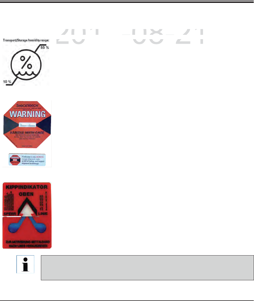
When delivering the instrument, the recipient must check that the ShockWatch impact
indicator and tilt indicator are intact. The responsible Leica representative must be no-
tified in the case that one or all indicators have been triggered.
Symbol: Title of the symbol: Humidity limitation for transport and storage
Description: Indicates the range of humidity for transport and
storage to which the medical device can be safely
exposed.
Appearance: Indication: ShockWatch Impact Indicator - Red - 50G
Functional description In the Shockwatch system, a precision glass tube
shows shocks or impacts that are above a specified
intensity through red coloration. Exceeding a defined
acceleration (g value) destroys the surface tension
of the liquid in the interior of the tube. This causes
the indicator tube to change color.
Appearance: Indication: Tilt indicator
Functional description Indicator to monitor whether the shipment has been
transported and stored in upright position according
to your requirements. With a pitch of 60° or more, the
blue quartz sand flows into the arrow-shaped indica-
tor window and sticks there permanently. Improper
handling of the shipment is immediately detectable
and can be proven definitively.
DRAFT
DRAFT
DRAFT
2014-08-21
Title of the s
y
mbol:
tle of the symb
Humidity limitation for transport
Humidity limitation for transport
D
escr
ip
t
i
on:
Description
Indicates the ran
g
e of humidit
ycates the range of humidity

11
Leica HistoCore SPECTRA ST
1. Important Information
1.2 Symbols and their meanings (continued)
US/Canada only:
This device complies with Part 15 of the FCC Rules and with Industry Canada
licence-exempt RSS standard(s).
Operation is subject to the following two conditions:
(1) this device may not cause harmful interference, and
(2) this device must accept any interference received, including interference
that may cause undesired operation.
Le présent appareil est conforme aux CNR d'Industrie Canada applicables
aux appareils radio exempts de licence. L'exploitation est autorisée aux
deux conditions suivantes:
(1) l'appareil ne doit pas produire de brouillage, et
(2) l'utilisateur de l'appareil doit accepter tout brouillage radioélectrique
subi, même si le brouillage est susceptible d'en compromettre le fonc-
tionnement.
This equipment has been tested and found to comply with the limits for a Class B digital device, pursu-
ant to Part 15 of the FCC Rules. These limits are designed to provide reasonable protection against
harmful interference in a residential installation. This equipment generates, uses and can radiate
radio frequency energy and, if not installed and used in accordance with the instructions, may cause
harmful interference to radio communications. However, there is no guarantee that interference
will not occur in a particular installation. If this equipment does cause harmful interference to radio
or television reception, which can be determined by turning the equipment off and on, the user is
encouraged to try to correct the interference by one or more of the following measures:
Reorient or relocate the receiving antenna.
Increase the separation between the equipment and receiver.
Connect the equipment into an outlet on a circuit different from that to which the receiver is
connected.
Consult the dealer or an experienced radio/TV technician for help.
Changes or modifications made to this equipment not expressly approved by Leica Biosystems
Nussloch GmbH may void the FCC authorization to operate this equipment.
FCC ID: 2AAPD-SPECTRAST
IC: 12028A-SPECTRAST
DRAFT
DRAFT
DRAFT
2014-08-21
This device com
p
lies with Part 15 of the F
CC
Rules an
This device complies with Part 15 of the FCC Rules an
12 Instructions for Use V 0.5 RevC - 08/2014
1. Important Information
Japan only:
Japanese Radio Law and Japanese Telecommunications
Business Law Compliance.
This device is granted pursuant to the Japanese Radio Law
(電波法) and the Japanese Telecommunications Business
Law (電気通信事業法)
This device should not be modified (otherwise the granted
designation number will become invalid)
CSA Statement (Canada/USA)
The CSA test mark means that a product has been tested and
fulfills the applicable safety standards:
CAN/CSA-C22.2 No. 61010-1-04;
CAN/CSA-C22.2 No. 61010-2-010-04;
CAN/CSA-C22.2 No. 61010-2-101-04
Product is listed under Master Contract Number: 217333
1.2 Symbols and their meanings (continued)
DRAFT
DRAFT
DRAFT
2014-08-21
J
a
p
anese
R
a
di
o
L
aw an
d
J
a
p
anese
T
e
nese Radio Law and Japanese Te
13
Leica HistoCore SPECTRA ST
1. Important Information
1.4 Qualification of personnel
1.5 Intended use of instrument
Any use of the instrument that deviates from the designated use is considered improper.
Failure to adhere to these instructions may result in an accident, personal injury, dam-
age to the instrument or accessory equipment. Proper and intended use includes com-
pliance with all inspection and maintenance instructions, along with the observance
of all instructions in the Instructions for Use as well as the constant inspection of the
reagents for storage life and quality. The HistoCore SPECTRA ST carries out the speci-
fied staining steps automatically. Thus, the manufacturer assumes no liability for the
staining results in the case that the staining steps and programs are entered incorrectly.
Thus, the end user is independently responsible for self-created reagents or program
entries.
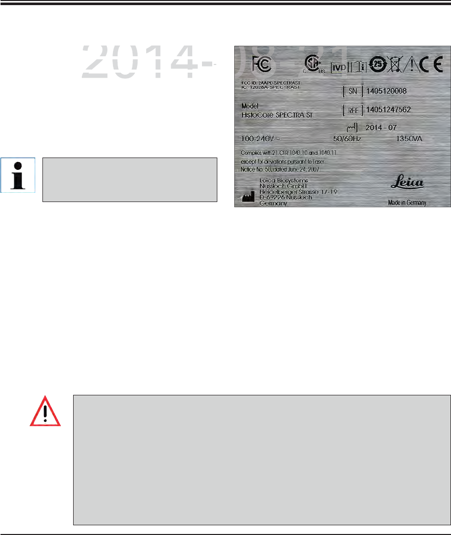
All information provided in these Instruc-
tions for Use applies only to the instru-
ment type indicated on the title page. A
nameplate indicating the instrument se-
rial number is attached at the left side of
the instrument. The accompanying Fig. 1
is provided as an example only and shows
a valid nameplate for this instrument.
Fig. 1
The exact data of the different in-
strument versions are specified in
Chap. 3.2.
1.3 Instrument type
The Leica HistoCore SPECTRA ST must only be operated by authorized personnel compre-
hensively trained in using lab reagents and their application in histology.
All laboratory personnel designated to operate this instrument must read these Instructions
for Use carefully and must be familiar with all technical features of the instrument before
attempting to operate it.
The Leica HistoCore SPECTRA ST is a staining machine for laboratory applications. It is in-
tended for the preparation of histological and cytological tissue samples.
The Leica HistoCore SPECTRA ST is also suitable for IVD (in vitro diagnostics).
DRAFT
DRAFT
DRAFT
2014-08-21
t
ion
p
rovided in these Instru
cion provided in these Ins
-
s
e applies only to the instr
ue applies only to the instru
--
ndicated on the title page Andicated on the title pa
08-21
14 Instructions for Use V 0.5 RevC - 08/2014
These Instructions for Use include important instructions and information related to the oper-
ating safety and maintenance of the instrument.
The Instructions for Use are an important part of the product, and must be read carefully prior
to startup and use and must always be kept near the instrument.
2. Safety
2.1 Safety notes
The safety and caution notes in this chapter must be observed at all times. Be sure to
read these notes even if you are already familiar with the operation and use of other
Leica products.
The protective devices located on the instrument and the accessories must not be re-
moved or modified.
Only qualified service personnel authorized by Leica may repair the instrument and
access its internal components.
Residual risks
The instrument has been designed and constructed with the latest state-of-the-art
technology and according to recognized standards and regulations with regard to
safety technology. Operating or handling the instrument incorrectly can place the
user or other personnel at risk of injury or can cause damage to the instrument or
property.
The instrument may be used only as intended and only if all of its safety features are
in proper working condition.
If malfunctions are to occur that can impede safety, the instrument must be put out of
operation immediately and the responsible Leica service technician must be notified.
Only original spare parts and permitted original Leica accessories may be used.
These Instructions for Use must be appropriately supplemented as required by the exist-
ing regulations on accident prevention and environmental safety in the operator‘s coun-
try.
The instrument's CE certificate can be found on the Internet at:
http://www.leicabiosystems.com
DRAFT
DRAFT
2014 08 21
safety and caution notes in this chapter must be observed at
ad these notes even if you are already familiar with the operat
eica prod cts
2014 08 21
15
Leica HistoCore SPECTRA ST
2. Safety
2.1 Safety notes (continued)
This instrument has been built and tested in accordance with the safety requirements for elec-
trical equipment for measurement, control, and laboratory use. To maintain this condition and
ensure safe operation, the user must observe all notes and warnings contained in these In-
structions for Use.
You must make sure that any data loaded onto the instrument is free of viruses. No
anti-virus software is provided.
The instrument is only suited for integration in a firewall-protected network. Leica
shall not assume any liability for errors due to integration in an unprotected network.
ONLY technicians trained and permitted by Leica can connect a USB input device
(mouse/keyboard, etc.). This also applies to the network connection, which is to be
used only together with RemoteCare (service diagnostics) and/or a LIS connection.
In the interest of specimen safety, the SPECTRA ST indicates when it is necessary for
the user to interfere using text messages and audible signals. Therefore, the SPECTRA
ST staining machine requires that the user is within hearing distance during operation.
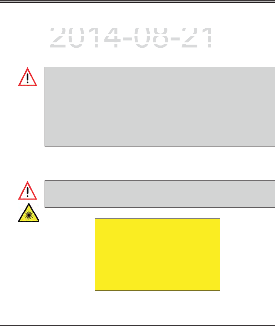
The product uses a class 1 laser source.
Caution, laser radiation! Do not look into the beam! This can cause injury to the con-
junctiva.
LASER RADIATION - DO NOT
STARE INTO BEAM
EN 60825-1: 2007
P<1 mW, O= 630 to 670 nm
Pulse duration = 500 μs
Class 1 laser product
DRAFT
DRAFT
DRAFT
2014-08-21
m
ent has been built and tested in accordance with the safet
yment has been built and tested in accordance with the safety
m
ent
f
or measurement, control, and laboratory use. To mai
nment for measurement, control, and laboratory use. To main
e operation the user must observe all notes and warningse operation the user must observe all notes and warnings
16 Instructions for Use V 0.5 RevC - 08/2014
2. Safety
2.2 Warnings
Warnings on the instrument
The safety devices installed in this instrument by the manufacturer only constitute the basis
for accident prevention. Operating the instrument safely is, above all, the responsibility of the
owner, as well as the designated personnel who operate, service or repair the instrument.
To ensure trouble-free operation of the instrument, make sure to comply with the following
instructions and warnings.
Please note that electrostatic discharges can result due to direct or indirect contact with the
SPECTRA ST.
Certain surfaces of the instrument are hot during operation under normal conditions.
They are marked with this warning sign. Touching these surfaces without suitable safe-
ty measures can cause burns.
Markings on the instrument surface showing the warning triangle indicate that the cor-
rect operating instructions (as defined in these Instructions for Use) must be followed
when operating or replacing the item marked. Failure to adhere to these instructions
may lead to accidents causing personal injury and/or damage to the instrument or ac-
cessories or destroyed, unusable specimens.
Safety notes on the instrument itself, which are marked with a round prohibitory sign,
indicate that the situation described by the symbol must be avoided and the correct op-
erating instructions (as defined in these Instructions for Use) must be followed when
operating the instrument marked. Failure to adhere to these instructions may lead to ac-
cidents causing personal injury and/or damage to the instrument or accessories or de-
stroyed, unusable specimens.
DRAFT
DRAFT
DRAFT
2014-08-21
s
trumen
tstrumen
i i t ll d i thi i t t b th f t li i t ll d i thi i t t b th f t l

17
Leica HistoCore SPECTRA ST
2. Safety
Warnings – Handling reagents
Warnings - Transport and installation
Take care when handling solvents!
Always wear protective clothing suitable for laboratory use, as well as rubber gloves
and safety goggles when handling the chemicals used in this instrument.
The installation site must be well-ventilated. Alternatively, the instrument can be
connected to an external exhaust air extraction system. The chemicals to be used in
the SPECTRA ST can be easily flammable and hazardous to health.
Do not operate the instrument in rooms with an explosion hazard.
When disposing of spent reagents, observe the applicable local regulations and the
waste disposal regulations of the company/institution in which the instrument is be-
ing operated.
Reagent cuvettes must always be filled outside of the instrument in compliance with
the safety information.
2.2 Warnings (continued)
The instrument must only be transported in an upright position.
The empty weight of the instrument is 185 kg; therefore, four qualified persons are re-
quired to lift or carry the instrument!
Use non-skid gloves to lift the device!
Leica recommends commissioning a transport company to transport, install or (where
applicable) relocate the instrument.
Place the instrument on a sturdy laboratory bench and adjust it to a horizontal posi-
tion.
Prevent the instrument from being exposed to direct sunlight!
Only connect the instrument to a grounded power socket. Do not interfere with the
grounding function by using an extension cord without a ground wire.
Exposure to extreme temperature changes between storage and installation locations
and high air humidity may cause condensation inside the instrument. If this is the
case, wait at least two hours before switching on the instrument.
The instrument must only be installed at the area of use with and under direction of
Leica-trained staff. This also applies to the potential transport to a new area of use.
We recommend using personnel trained by Leica to recommission the instrument.
DRAFT
DRAFT
DRAFT
2014-08-21
s
port an
d
i
nsta
ll
at
i
o
nsport and installation
lb di
2014 08 21
18 Instructions for Use V 0.5 RevC - 08/2014
2. Safety
Warnings – Operating the instrument
The instrument may be operated by trained laboratory personnel only. It must only be
operated for the purpose of its designated use and according to the instructions con-
tained in these Instructions for Use. Antistatic protective clothing made from natural
fibers (e.g. cotton) should be worn when working with the instrument.
In the event of an emergency, switch off the power switch and unplug the instrument
from the power supply (circuit breaker in accordance with EN ISO 61010-1).
There is a fire hazard if work with an exposed flame (e.g. Bunsen burner) is carried
out in the direct vicinity of the instrument (solvent vapors). Therefore, keep all ignition
sources at least 2 meters away from the instrument!
Be absolutely certain to operate the instrument either with the active carbon filter,
technical ventilation system and an exhaust hose, as even when the instrument is
used according to its designated use, solvents arise that are both hazardous to health
and inflammable!
For the instrument fume control, Leica recommends a delivery volume of 50 m3/h and
an air exchange rate of 8 (25 m3/m2h) in the lab.
Opening the hood when one or more staining program(s) are active causes delays
in the respective processing steps since no transport movements take place for this
time frame. This can result in changes to the staining quality.
Make sure to keep the hood closed if the staining programs are active. Leica assumes
no liability for loss of quality for staining programs caused by opening the hood dur-
ing the staining process.
CAUTION when closing the hood: Crushing hazard! Do not reach into the swivel range
of the hood!
2.2 Warnings (continued)
DRAFT
DRAFT
DRAFT
2014-08-21
i
ng the instrumen
tng the instrume
2014 08 21
19
Leica HistoCore SPECTRA ST
2. Safety
2.2 Warnings (continued)
Before any maintenance, switch off the instrument and unplug it from power supply.
When using cleaners, please comply with the safety instructions of the manufacturer
and the laboratory safety regulations.
The plastic reagent cuvettes of the rinsing water and reagent stations can be cleaned
in a dishwasher at a maximum temperature of +65 °C. Any standard cleaning agent
for laboratory dishwashers may be used. Never clean the plastic reagent cuvettes at
higher temperatures since it can cause the reagent cuvettes to become deformed!
Do not use any of the following for cleaning the outside surfaces of the instrument:
alcohol, detergents containing alcohol (glass cleaners), abrasive cleaning powders,
solvents containing acetone, ammonia, chlorine, or xylene!
Wear suitable protective clothing when cleaning the instrument (lab coat and
gloves). Clean the hoods and housing using mild commercial, pH-neutral household
cleaners. The finished surfaces are not resistant to solvents and xylene substitute!
Warnings – Maintenance and cleaning
Warnings – Operating the instrument (continued)
No liquid may reach behind covers and in columns when working and cleaning. This
also applies for transport arms.
CAUTION for programs that start with an oven step! In this case, the load station from
which the specimen slide is removed with the transport arm must NOT be filled with
a flammable reagent (e.g. xylene, xylene substitute or alcohols). The oven tempera-
ture can be up to 70 °C. This can result in the reagent igniting and can cause damage
to the instrument and specimens.
CAUTION when filling the heated reagent cuvettes. Flammable reagents (e.g. xylene,
xylene substitute or alcohols) must not be added to the heated reagent cuvettes.
DRAFT
DRAFT
2014-08-21
r
ating the instrument
rating the instrument
(
continued
)(continued)
2014 08 21
20 Instructions for Use V 0.5 RevC - 08/2014
2. Safety
2.3 Safety features on the instrument
As soon as the hood of the instrument is opened, the movements of the transport arms are
stopped in a horizontal plane (x and y-axis) for safety reasons to eliminate specimen damage
due to collision with moving parts.
Make sure to keep the hood closed if the staining programs are active. Leica assumes
no liability for loss of quality for staining programs caused by opening the hood dur-
ing the staining process.
Opening the hood when one or more staining program(s) is/are active causes delays
in the respective processing steps since no transport movements take place for this
time frame. This can result in changes to the staining quality.
DRAFT
DRAFT
DRAFT
2014-08-21
e
hood of the instrument is o
p
ened, the movements of the
e hood of the instrument is opened, the movements of the
o
rizontal plane
(
x and y-axis
)
for safety reasons to eliminat
erizontal plane (x and y-axis) for safety reasons to eliminate
n
with movin
g
p
arts
.n with moving part

21
Leica HistoCore SPECTRA ST
3. Instrument Components and Specifications
3.1 Standard delivery—packing list
Qty Designation Order No.
1 SPECTRA ST basic instrument 14 0512 47567
1 Power cable country-specific
46 Reagent cuvettes, assembly, including reagent cuvette cover 14 0512 47086
6 Water flow cuvettes, assembly 14 0512 47087
6 O-rings 7x2, for water flow cuvette connecting piece 14 0253 47088
Sanitation and water supply equipment accessories:
1Outlet hose, length: 2 m 14 0475 35747
2Inflow hoses, Ø 10 mm, length: 2.5 m 14 0474 32325
1 Pressure hose, 1.5 m extension 14 0512 49334
1 Y piece 14 3000 00351
2 Double nipple G3/4 G3/8 14 3000 00350
1 Water filter housing 14 0512 49331
1 Filter cartridge 14 0512 49332
1Bushing G 3/4 14 3000 00360
1 Exhaust hose, 2 m 14 0475 35762
2 Active carbon filter 14 0512 47131
3 Rack for 30 specimen slides (3 pcs. per package) 14 0512 52473
1 Clip for rack for 30 specimen slides (yellow, 3 pcs. per package) 14 0512 52576
1 Clip for rack for 30 specimen slides (dark blue, 3 pcs. per package) 14 0512 52478
1 Clip for rack for 30 specimen slides (red, 3 pcs. per package) 14 0512 52480
1 Clip for rack for 30 specimen slides (white, 3 pcs. per package) 14 0512 52484
1 Instructions for Use, printed (German/English, with
Language CD 14 0512 80200)
14 0512 80001
DRAFT
DRAFT
DRAFT
3
.
3.
Instrument
C
om
p
Instrument Com
2014-08-21
a
tion
on
A
S
T basic instrument
A ST basic instrum

22 Instructions for Use V 0.5 RevC - 08/2014
3. Instrument Components and Specifications
3.2 Technical Data
Nominal supply voltages: 100-240 V AC +10 %
Nominal frequency: 50/60 Hz
Power draw: 1350 VA
Fuses: 2 x T16 A H 250 V AC
IEC 1010 classification: Protection class 1
Pollution degree: 2
Overvoltage category: II
Fresh water connection:
Hose material: PVC
Hose length: 2500 mm
Connecting piece: G3/8
Inner diameter: 10 mm
Outer diameter: 16 mm
Internal pressure: Minimum: 2 bar
Maximum: 6 bar
Required flow rate: Min. 1,7 l/minute
Required water quality: Type 1, ISO 3696
Waste water connection:
Hose length: 2000 mm/4000 mm
Inner diameter: 32 mm
Outer diameter: 36.8 mm
Exhaust air:
Hose length: 2000 mm
Inner diameter: 50 mm
Outer diameter: 60 mm
Exhaust performance: 27.3 m3/h
DRAFT
DRAFT
ts and
Sp
ecification
s
ts and Specification
p
2014-08-21
a
ges:
es:
8
1
00
-
2
4
000-240
V
A
C
V AC
+
1
0
%
5
0
/
60
0/60
H
z
Hz
23
Leica HistoCore SPECTRA ST
3. Instrument Components and Specifications
Exhaust extraction: Active carbon filter and exhaust hose for connect-
ing with an external exhaust system
Heat emission: 1350 J/s
A-weighted noise level: < 70 dB (A)
International protection class: IP20
Sockets 1 x RJ45 Ethernet (rear): RJ45 - LAN (external data management)
1 x RJ45 Ethernet (front): Only for service purposes
2 x USB 2.0: 5 V/500 mA (service & data storage)
3.2 Technical data (continued)
When using an external uninterruptible power supply (UPS), it should be designed for a
capacity of at least 1350 VA and secure operation over a time frame of at least 10 min-
utes.
Ambient conditions:
Operation:
Temperature: +18 °C to +30 °C
Relative humidity: 20 % to 80 %, non-condensing
Operating elevation: Up to a max. of 2000 m above sea level
Storage:
Temperature: +5 °C to +50 °C
Relative humidity: 10 % to 85 %, non-condensing
Transport:
Temperature: -29 °C to +50 °C
Relative humidity: 10 % to 85 %, non-condensing
Dimensions and weight
Dimensions (length x depth x height): Hood closed: 135.4 x 78.5 x 58.5 cm
Hood open: 135.4 x 78.5 x 94.3 cm
Empty weight (without reagents and accessories): 185 kg
DRAFT
DRAFT
DRAFT
3
.
3.
Instrument
C
om
p
Instrument Com
2014-08-21
o
n: A
c
tiv
e
ca
r
bo
n filt
e
r
a
n
d
e
x
hctive carbon filter and exh
i
ng w
i
t
h
an externa
l
ex
h
a
uing with an external exhau
24 Instructions for Use V 0.5 RevC - 08/2014
3. Instrument Components and Specifications
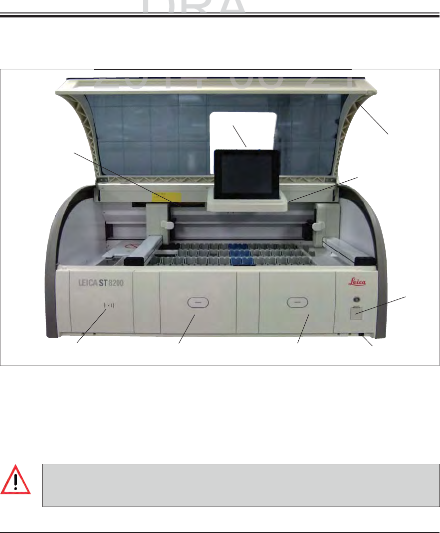
3.3 Overview
Fig. 2
Front view
1
234
5
6
1Insert for active carbon filter 6Screen with user interface
2Read-in area for Leica reagents 7a USB sockets (2 pcs.),
3Input drawer 7b Service access
4Output drawer 8ON/OFF switch
5Screen holder with interior lighting 9Lid
7a/b
8
9
The service access (7b, Fig. 2) may only be used by service technicians certified by Leica!
The cover of the read-in area (2, Fig. 2) may only be removed by a service technician certified
by Leica.
DRAFT
DRAFT
DRAFT
ts and
Sp
ecification
s
ts and Specification
p
2014-08-21
2014 08 21
2014 08 21
25
Leica HistoCore SPECTRA ST
3. Instrument Components and Specifications
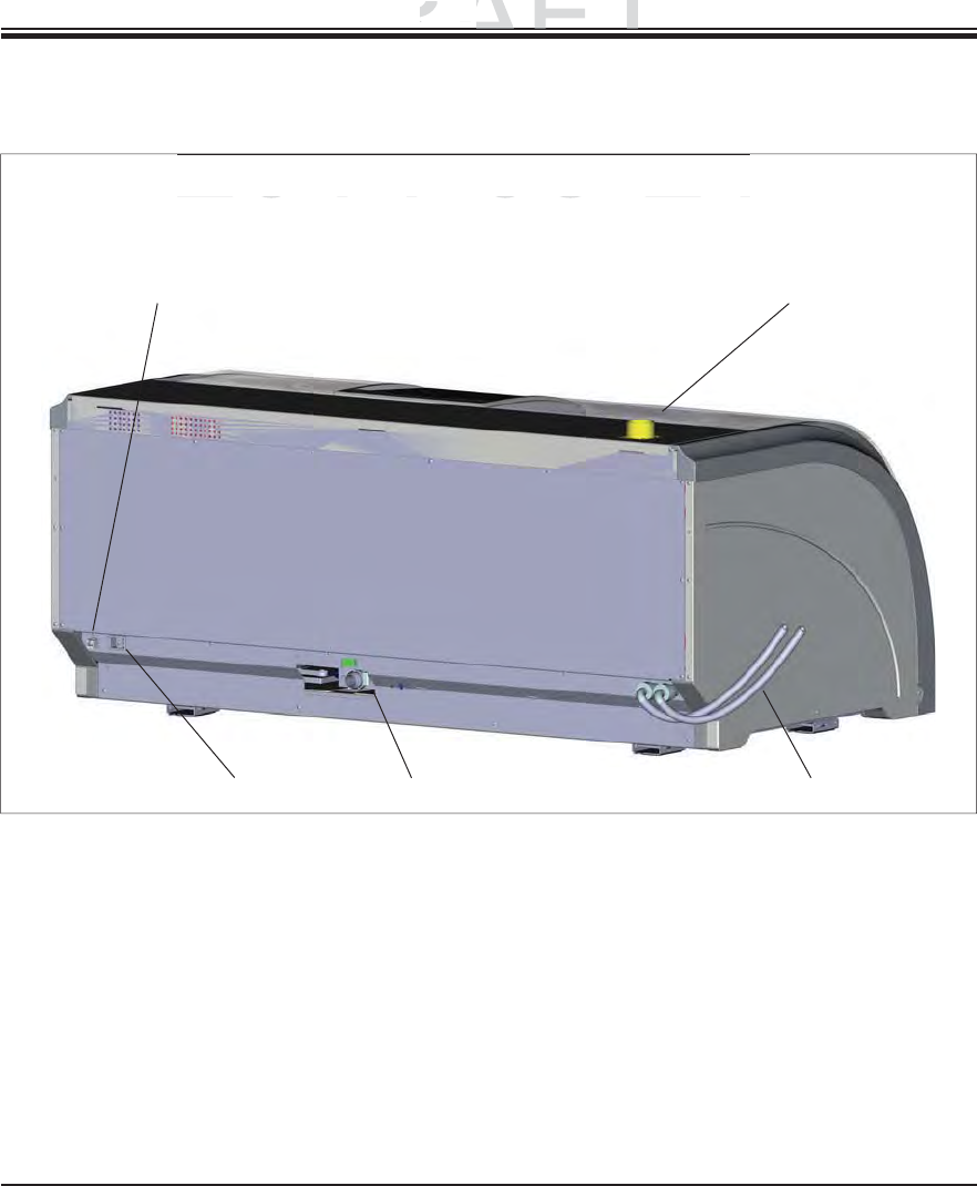
Fig. 3
Rear view
3.3 Overview(continued)
1Network connection (RemoteCare/LIS)
2Power supply
3Waste outlet
4Running water connections
5Exhaust air connection
1
234
5
DRAFT
DRAFT
DRAFT
3
.
3.
Instrument
C
om
p
Instrument Com
2014-08-21
2014 08 21
26 Instructions for Use V 0.5 RevC - 08/2014
3. Instrument Components and Specifications
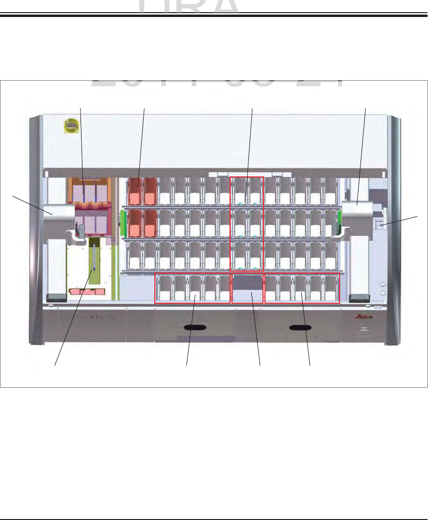
3.3 Overview(continued)
Inside view
Fig. 4
1Left transport arm 6Transfer station for SPECTRA CV (optional)
2Specimen slide reader module 7Right transport arm
3Load station, 5 pcs. 8Rinsing water stations, 6 pcs.
4Dry transfer stations, 2 pcs. 9Heated reagent stations, 4 pcs. (optional)
5Unload station, 5 pcs. 10 Drying oven stations, 6 pcs
1
2345
6
78
910
DRAFT
DRAFT
DRAFT
ts and
Sp
ecification
s
ts and Specification
p
2014
-
08
-
21
2014 08 21
27
Leica HistoCore SPECTRA ST
It must be ensured that there is a mostly vibration-free floor and sufficient clear space (ap-
prox. 1.10 cm) above the laboratory bench to allow unobstructed opening of the lid.
Condensation water may form in the instrument if there is an extreme difference in tempera-
ture between the storage location and the installation site and if air humidity is high at the
same time. A waiting time of at least two hours must be observed each time before switching
on. Failure to comply with this may cause damage to the instrument.
Stable, exactly horizontal and level laboratory bench at least 1.40 m wide and 0.80 m deep.
The counter area must be designed for handling loads of at least 150 kg/m2, vibration-free
and level.
Fume hood at a max. 2.0 m distance from the instrument.
The instrument is suitable for operation in indoor areas only.
The operating location must be well-ventilated and have an air exhaust.
A running water connection must be available at a maximum distance of 2.5 m. This connec-
tion must also be easily accessible after installing the instrument.
A waste water connection must be available at a maximum distance of 2 m. This connection
must be connected to the instrument with constant outlet hose slope.
4.1 Installation site requirements
A connection to an external exhaust system, a technical room ventilation system and
an integrated exhaust system with an active carbon filter reduce the concentration of
solvent vapor in the room air. The active carbon filters must be used for connecting to
an external exhaust system as well. Compliance with this is mandatory.
The instrument operator bears responsibility for complying with workplace limits in
accordance with the hazardous substances ordinance and the measures necessary
for this, including documentation.
A grounded power supply socket must be available at a maximum distance of 3 m.
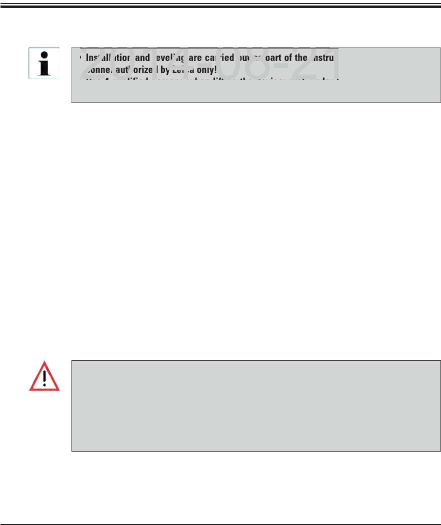
4. Installation and Starting Up
Installation and leveling are carried out as part of the instrument installation by per-
sonnel authorized by Leica only!
Use 4 qualified persons when lifting the device; grab under the frame at all corners
and lift evenly.
DRAFT
DRAFT
DRAFT
4
. I
n
2014 08 21
nstallation and leveling are carried out as part of the instrum
sonnel authorized by Leica only!
Use 4 q alified persons hen lifting the de ice grab nder t
2014 08 21
28 Instructions for Use V 0.5 RevC - 08/2014
4. Installation and Starting Up
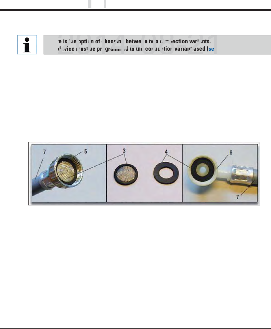
4.2 Running water connection
There is the option of choosing between two connection variants.
The device must be programmed to the connection variant used (see Chap. 6.5).
The following installation instructions apply for both types of connections:
Remove the rinsing water supply hose (7) from the packaging, being careful of the two
gaskets (4).
Insert one gasket (4) into the screw connection (6) on the instrument.
Keep other gaskets as replacements.
Insert the filter screen (3), as shown in Fig. 5, into the retaining ring (5) that is fastened to
the water tap. Do not use another gasket since the filter screen acts as a sealing simulta-
neously.
Fig. 5
DRAFT
DRAFT
DRAFT
ng U
p
ng Up
p
2014-08-21
s the option of choosing between two connection variants.
device must be programmed to the connection variant used
ee
2014-08-21
29
Leica HistoCore SPECTRA ST
4. Installation and Starting Up
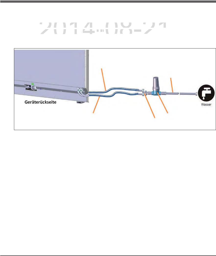
If all water flow cuvettes (6 running water stations) are to be connected to a joint running water
connection, both supply hoses (see Fig. 6) are used at the same time:
1
2
5
3
4
1Rinsing water supply hose 1 (2.5 m) Order No.: 14 0474 32325
2Pressure hose (1.5 m) Order No.: 14 0512 49334
3Rinsing water supply hose 2 (2.5 m) Order No.: 14 0474 32325
4Y piece Order No.: 14 3000 00351
5Filter Order No.: 14 0512 49331
Fig. 6
4.2.1 Joint connection of all 6 rinsing water stations
DRAFT
DRAFT
DRAFT
4.
I
n
2014-08-21
low cuvettes
(
6 running water stations
)
are to be connected
low cuvettes (6 running water stations) are to be connected
,
both supply hoses
(both supply hoses (
see
Fi
g
.see Fig.
66
)
are used at the same time:
) are used at the same t
30 Instructions for Use V 0.5 RevC - 08/2014
4. Installation and Starting Up
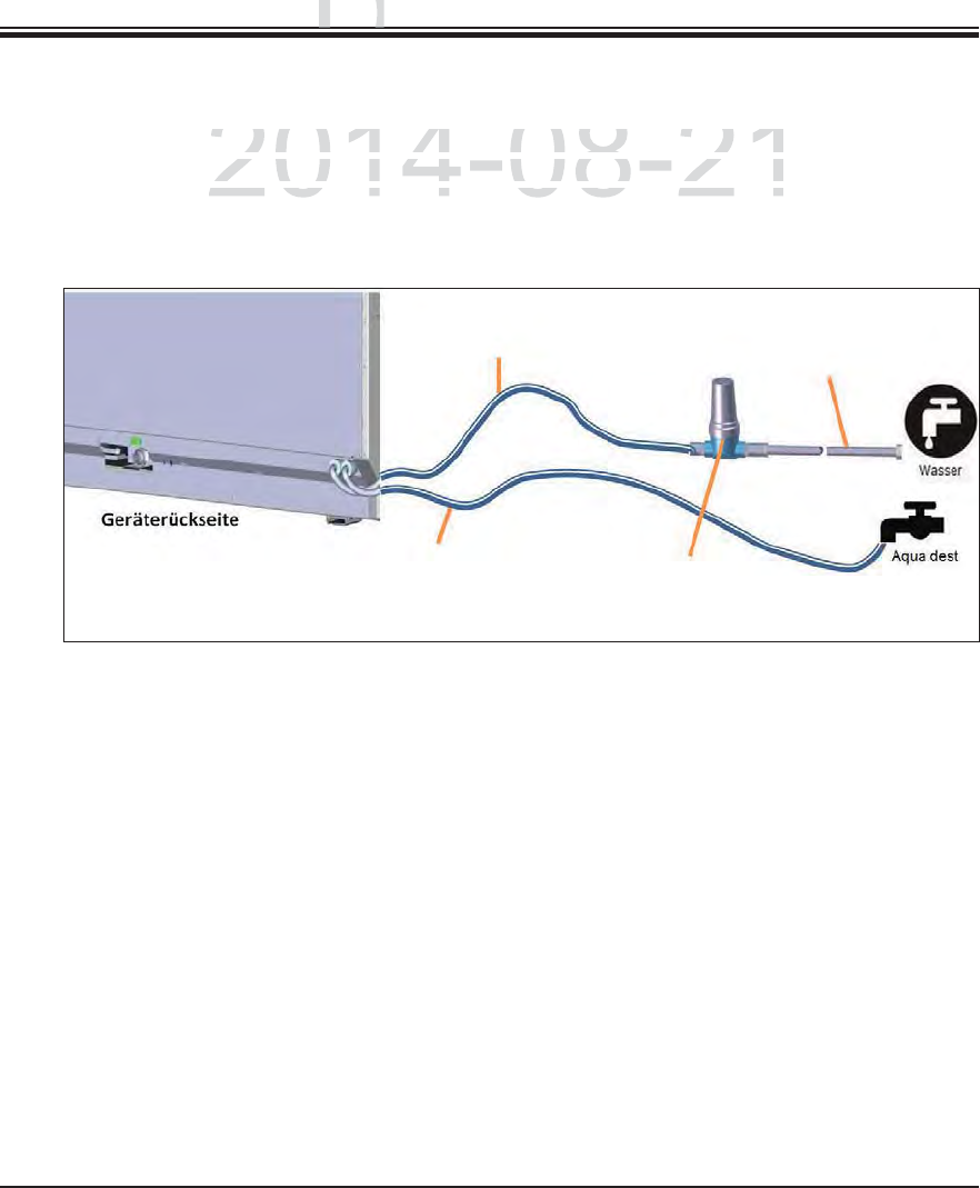
4.2.2 Combined connection 4+2 rinsing water stations
If the main connection (4 rinsing water stations) is to be connected to fresh water and the sec-
ondary connection (2 rinsing water stations) is to be connected to a supply in the laboratory
with distilled or desalinated water (aqua dest. or demineralized water), proceed in accordance
with the following connection diagram:
Fig. 7
1Rinsing water supply hose 1 (2.5 m) Order No.: 14 0474 32325
2Pressure hose 3 (1.5 m) Order No.: 14 0512 49334
3Rinsing water supply hose 1 (2.5 m) Order No.: 14 0474 32325
4Filter Order No.: 14 0512 49331
12
34
DRAFT
DRAFT
DRAFT
n
g
U
p
ng Up
gp
2014-08-21
nection
(
4 rinsing water stations
)
is to be connected to fres
hnection (4 rinsing water stations) is to be connected to fresh
c
tion
(
2 rinsing water stations
)
is to be connected to a sup
ption (2 rinsing water stations) is to be connected to a supp
r desalinated water (aqua dest or demineralized water) pror desalinated water (aqua dest or demineralized water) pro
31
Leica HistoCore SPECTRA ST
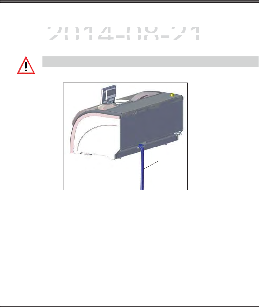
4.2.3 Wastewater connection
The instrument has a passive wastewater outflow. The lab outflow siphon must therefore be
located at least 50 cm under the wastewater connection of the instrument.
The outlet hose (1, Fig. 8) must be routed at a constant slope and must not be elevated.
4. Installation and Starting Up
Fig. 8
1
DRAFT
DRAFT
DRAFT
4.
I
n
2014-08-21
r
ument has a passive wastewater outflow. The lab outflow s
iument has a passive wastewater outflow. The lab outflow si
a
t
l
east 50
t least 5
cm under the wastewater connection o
f
the inst
rcm under the wastewater connection of the instr
32 Instructions for Use V 0.5 RevC - 08/2014
4. Installation and Starting Up
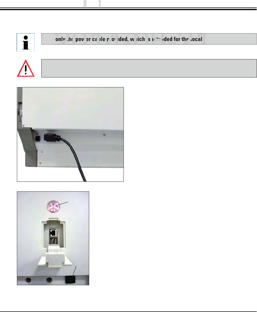
Use only the power cable provided, which is intended for the local power supply.
Connect the power cable to the power input
socket on the rear panel of the instrument
(Fig. 9).
Plug the power plug into a grounded power
socket.
Fig. 9
Before connecting the instrument to the power supply, make sure that the main switch
on the front right side of the instrument is in the OFF ("0") position.
4.3 Electrical Connection
Fig. 10
1
2
Switch on the power switch (1, Fig. 10).
After a short period of time, the operating
switch lights up orange (2, Fig. 10); once the
software has completely started, it lights up
red and the instrument is in standby mode.
The operating switch can then be operated
(see Chap. 4.5).
DRAFT
DRAFT
DRAFT
ng U
p
ng Up
p
2014-08-21
ly the power cable provided, which is intended for the local p
2014-08-21
33
Leica HistoCore SPECTRA ST
4. Installation and Starting Up
4.4 Exhaust air connection
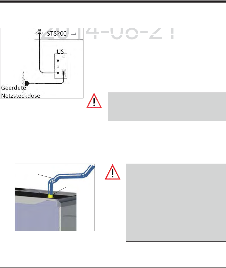
4.3.1 Using an external uninterruptible power supply (UPS)
The UPS power cable must always remain in the
power socket in the lab, even in the event of a power
outage. Otherwise grounding of the instrument can-
not be ensured!
A connection to an external exhaust system
and an integrated exhaust system with an
active carbon filter reduce the concentration
of solvent in the room air and must be used.
The cuvettes must be covered when not us-
ing the instrument to prevent the unneces-
sary evaporation of the reagents.
When working with hazardous materials,
compliance with the workplace limit values
according to the ordinance on protection
from hazardous substances must be inspect-
ed by the operator.
Connect one end of the exhaust hose (1, Fig. 12) to the exhaust port (2, Fig. 12) on the top
side of the instrument. Connect the other end to an exhaust air device installed in the lab.
An interruption of the staining process can be avoided in the
event of a temporary power failure by connecting a battery-
buffered uninterruptible power supply (UPS). The UPS should
enable an output of at least 1350 VA for the duration of 10 min-
utes. The UPS must be designed for operating voltage at the
installation location. The connection is carried out by connect-
ing the SPECTRA ST power cable to the UPS power output
socket. The UPS is connected to the power socket in the lab.
Fig. 11
Fig. 12
2
1
DRAFT
DRAFT
DRAFT
4.
I
n
2014-08-21
An interruption o
f
the staining proces
sAn interruption of the staining process
event of a tem
p
orar
y
p
ower failure b
ynt of a temporary power failure by
201
34 Instructions for Use V 0.5 RevC - 08/2014
4. Installation and Starting Up
4.5 Switching the instrument on and off
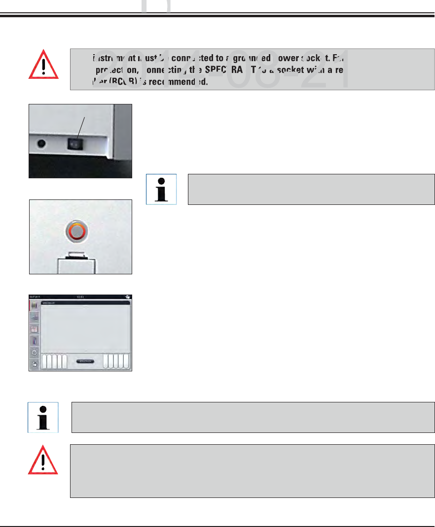
The instrument must be connected to a grounded power socket. For additional electrical
fuse protection, connecting the SPECTRA ST to a socket with a residual current circuit
breaker (RCCB) is recommended.
If using the oven is programmed in the staining program as the first step, the program
can be marked "not startable" after switching on the instrument since the oven has not
yet reached operating temperature. As soon as the operating temperature is attained,
the program is displayed as startable.
Switch the power switch on the front right side at the bottom of
the instrument to ON ("I"). (See 1, Fig. 13)
A few seconds after switching on the power switch, the operat-
ing switch is illuminated in orange (Fig. 14). The software's start
process ends when the operating switch illuminated in red.
To start the instrument, press the operating switch illuminated
in red.
During initialization, a verification of all stations ("fill level scan")
is carried out automatically.
The operating switch is illuminated in green whenever the instru-
ment is ready to start.
After completing the initialization phase, the main menu appears
on the screen (see Fig. 15).
Switching off the instrument
To switch the instrument into standby mode (e.g. overnight), press
the operating switch. It then illuminates in red.
For cleaning and maintenance, also switch off the instrument on
the power switch (see 1, Fig. 13).
Fig. 13
Fig. 14
Fig. 15
Pushing the operating switch in the orange phase does
not start the instrument.
During the instrument setup or if no reagents are added, non-filled stations are identi-
fied and highlighted on the screen (see Chap. 6.2.2)
1
DRAFT
DRAFT
DRAFT
ng U
p
ng Up
p
instrument must be connected to a grounded power socket. For a
rotection, connecting the SPECTRA ST to a socket with a res
aker (RCCB) is recommended
35
Leica HistoCore SPECTRA ST
5. Operation
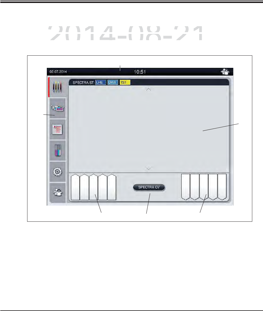
5.1 User interface – overview
The SPECTRA ST is programmed and operated using a color touchscreen. The screen ap-
pears as follows after switching on if there is no staining process (program) running.
Fig. 16
6
3
1
2
54
1Status bar 4Button for the SPECTRA CV process display
2Process status display 5Input drawer status display
3Output drawer status display 6Main menu (see Chap. 5.5)
DRAFT
DRAFT
DRAFT
2014-08-21
C
TRA
S
T is
p
ro
g
rammed and o
p
erated usin
g
a color touch
sCTRA ST is programmed and operated using a color touchs
s
follows after switching on if there is no staining process
(pfollows after switching on if there is no staining process (p
36 Instructions for Use V 0.5 RevC - 08/2014
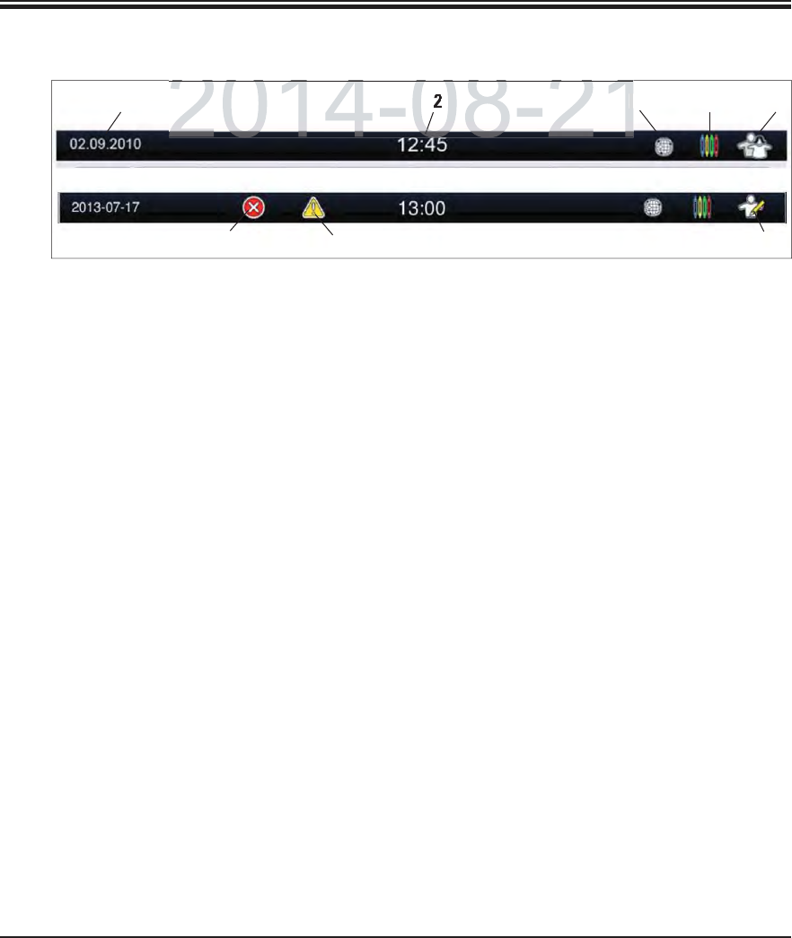
5.2 Status bar elements
Fig. 17
1Current date
2Local time
3The "Remote Care access" symbol indicates that this instrument is connected to the
Leica Remote Care Service via a network connection.
4The "process" symbol indicates that staining processes are currently active.
5This "user" symbol indicates that the instrument is in user mode, which enables simpli-
fied operation of the instrument without a password.
6The operation of this instrument in "Supervisor Mode" is displayed by this symbol. This
mode provides additional operation and adjustment options for trained staff. Access
to this mode is password-protected.
7If warnings and notes are displayed during operation, the symbol depicted appears.
Pressing this symbol allows the last 20 messages to be called up again.
8If alarms and error messages are displayed during operation, this alarm symbol appears.
Pressing this symbol allows the last 20 messages to be called up again.
1235
67 8
4
5. Operation
DRAFT
DRAFT
DRAFT
2014 08 21
2014 08 21
3
37
Leica HistoCore SPECTRA ST
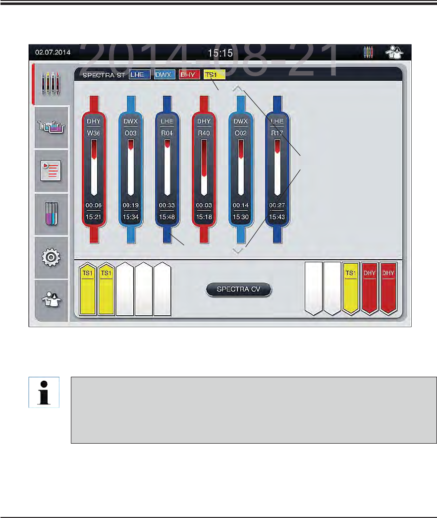
5.3 Process status display
All slide racks located in the process (3) are displayed in the main window (Fig. 18).
The title bar of the main window (2, Fig. 18) indicates the instrument type [SPECTRA ST] and
lists the currently bootable staining programs with the defined abbreviations and the color
assigned to the slide racks.
Fig. 18
5. Operation
1
2
3
To display an active staining process, the upper part of the clip is displayed symboli-
cally in the respective color (3, Fig. 18). If the number of racks in the process exceeds
the maximum that can be displayed in the main window (max. 9), you can scroll through
the display area vertically using the keys (1, Fig. 18). If one of the buttons is grayed out,
it is disabled and there are no other elements in an area that is not shown.
DRAFT
DRAFT
DRAFT
2014 08 21
38 Instructions for Use V 0.5 RevC - 08/2014
1
2
3
4
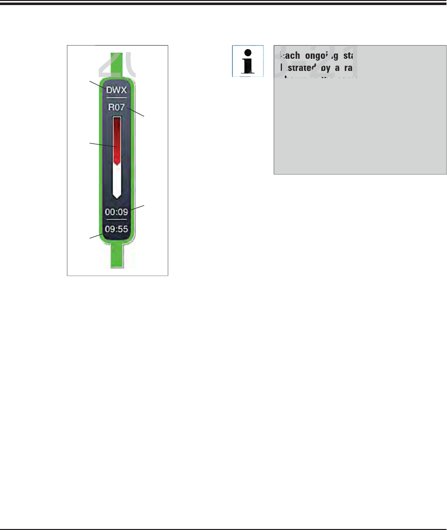
5.3 Process status display (continued)
Fig. 19
5. Operation
If the SPECTRA ST staining machine is connect-
ed to the SPECTRA CV robotic coverslipper per-
manently, the combination of both instruments
represents an instrument unit (workstation).
This enables an interruption-free workflow from
the staining process up to the removal of the fin-
ished cover slipped slides.
The current process status of both instruments
can be shown on the screen of the SPECTRA ST
staining machine.
Pressing the "SPECTRA CV" (3, Fig. 20) or "SPEC-
TRA ST" button allows you to change between
the status displays of the staining machine and
robotic coverslipper.
The progress display is divided into two sections
in workstation mode with a connected SPECTRA
CV. The upper section displays the progress in
the stainer.
The lower area shows the coverslipping prog-
ress in the SPECTRA CV (see Chap. 6.7.5).
1Abbreviation of the program
2Current position of the slide rack in
the instrument
3Progress display of the entire stain-
ing process
4Estimated remaining time at the
current station (hh:mm)
5Remaining time until the end of the
program (hh:mm)
Each ongoing staining process is il-
lustrated by a rack clip symbol. It is
shown in the same color as the actual
rack clip. Various information is dis-
played on the clip symbol (see Fig. 19).
Fig. 19 shows the status display on the
SPECTRA ST without connected ro-
botic coverslippers. For displaying the
status display in workstation opera-
tion, see Chap. 6.7.5.
4
DRAFT
DRAFT
DRAFT
2014-08-21
201
Each ongoing stai
lustrated by a rac
hith
8-21
08
39
Leica HistoCore SPECTRA ST
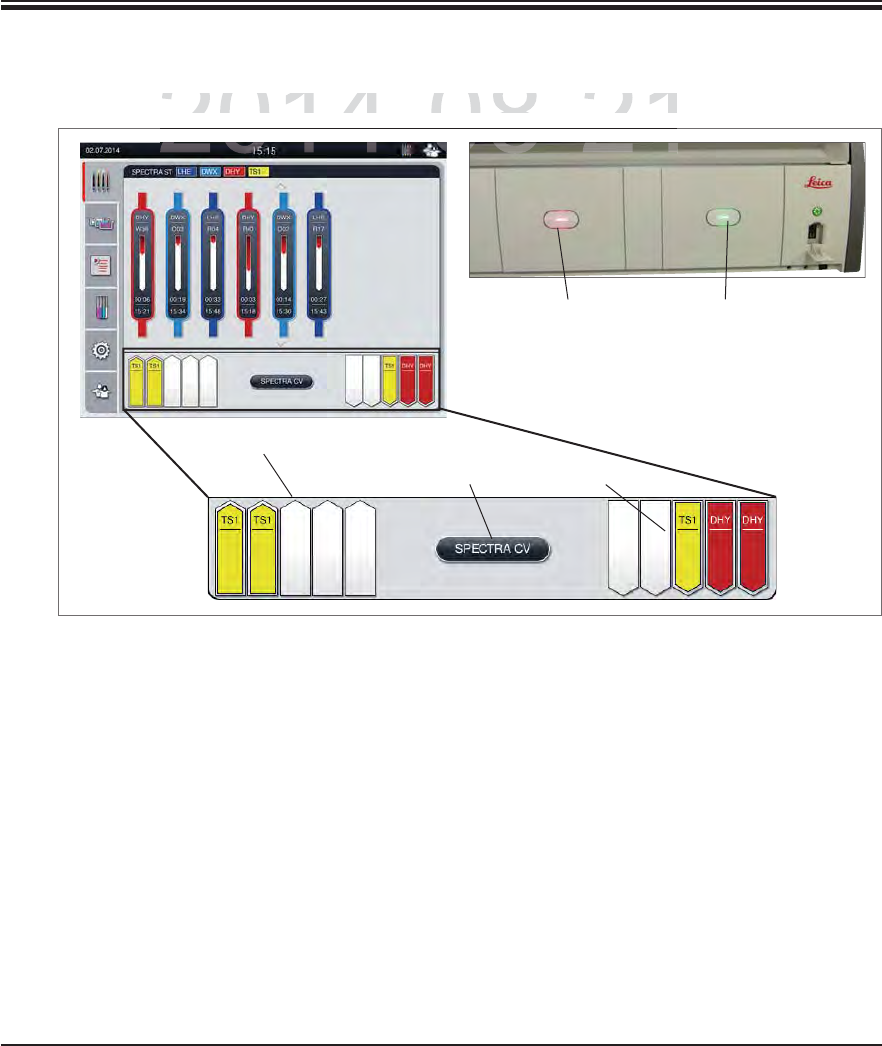
5.4 Displaying the drawers
The stations displayed using the direction of the arrow pointing into the instrument (1, Fig. 20)
symbolize the input drawer. The stations displayed using the direction of the arrow pointing
out of the instrument (2, Fig. 20) symbolize the output drawer with five positions each.
The respective drawer is opened or closed automatically by pressing the drawer button (4
or 5, Fig. 20).
The device automatically recognizes if slide racks are inserted or removed when the drawer
is closed.
The slide racks located in the input or output drawer are shown on the screen with the
respective slide rack handle color and the assigned program abbreviation.
Available positions are shown in white and without a label.
Fig. 20
5. Operation
1
32
The lower area of the main window illustrates the status of the input and output drawers.
45
DRAFT
DRAFT
DRAFT
2014-08-21
2014-08-21
rea of the main window illustrates the status of the input a
nrea of the main window illustrates the status of the input an
08 21
40 Instructions for Use V 0.5 RevC - 08/2014
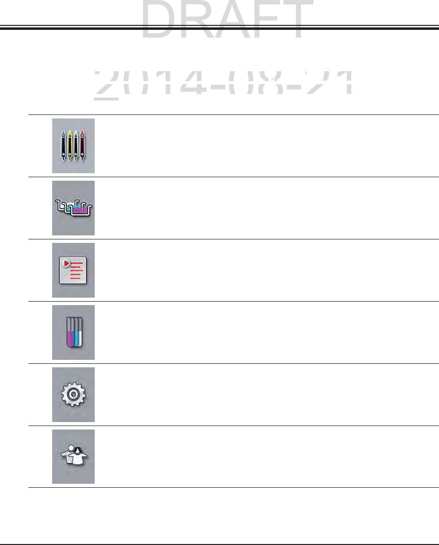
5.5 Main menu-overview
The main menu is located on the left side of the display (see Fig. 18), which is divided into sec-
tions as described below. This menu is visible in all submenus and allows switching to another
submenu at any time.
The "process status display" displays the current status of all racks
located in the process. Here, the respective clip of the rack is displayed
symbolically with the respective color.
This display shows the standard display.
The "bathlayout" displays the top view of all stations within the instru-
ment. The individual reagent stations are displayed with reagent names,
station numbers and slide racks located in the process.
After activating the "program list", all staining programs available in the
instrument are displayed in list form. The menu enables re-entering and
changing staining programs, their prioritization and the creation of the
bathlayout.
After activating the "reagent list", all previously entered reagents are
displayed in list form. The menu enables the modification or re-entering
of staining reagents, e.g. for integrating new staining programs. The
reagents must be entered before creating the program.
Basic settings can be configured in the "Settings" menu. The language
version, date and time as well as oven temperature and other parameters
can be adjusted to the local requirements here.
In the "User Settings" menu, a password can be set up to prevent
modifications to the programs and reagent lists by unauthorized persons
("Supervisor mode"). However, the instrument can be used without a
password in "User Mode".
5. Operation
DRAFT
DRAFT
2014-08-21
u
is located on the left side of the display
u is located on the left side of the display
((
s
ee
Fi
g.
see Fig.
1
8
))
, w
hi
c
h, which
b
e
d
b
e
l
ow.
Thi
s menu
i
s v
i
s
ibl
e
i
n a
ll
su
b
menus an
d
a
ll
ows
sbed below. This menu is visible in all submenus and allows s
y timey time
41
Leica HistoCore SPECTRA ST
5. Operation
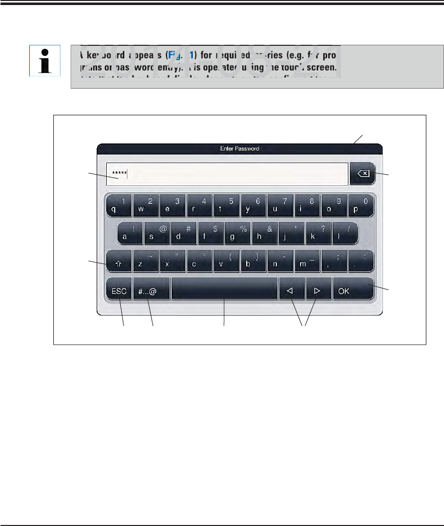
5.5.1 The keyboard
1Title bar 8Cancel (entries are not saved!)
2Input field
3Delete most recently entered character 9Upper and lowercase (holding the button
activates caps lock, displayed by coloring
the button red. Pressing again re-activates
lowercase.)
4Confirmation
5Move cursor to left or right
6Space key
7Special character toggle button (Fig. 22)
3
4
1
568 7
2
9
Fig. 21
A keyboard appears (Fig. 21) for required entries (e.g. for programming, creating pro-
grams or password entry). It is operated using the touch screen.
Note that the keyboard display depends on the configured language.
DRAFT
DRAFT
DRAFT
eyboard appears
Fig.
2
required entries (e.g. for prog
rams or password entry). It is operated using the touch screen.
2014 08 21
Note that the ke board displa depends on the config red lang a
2014 08 21
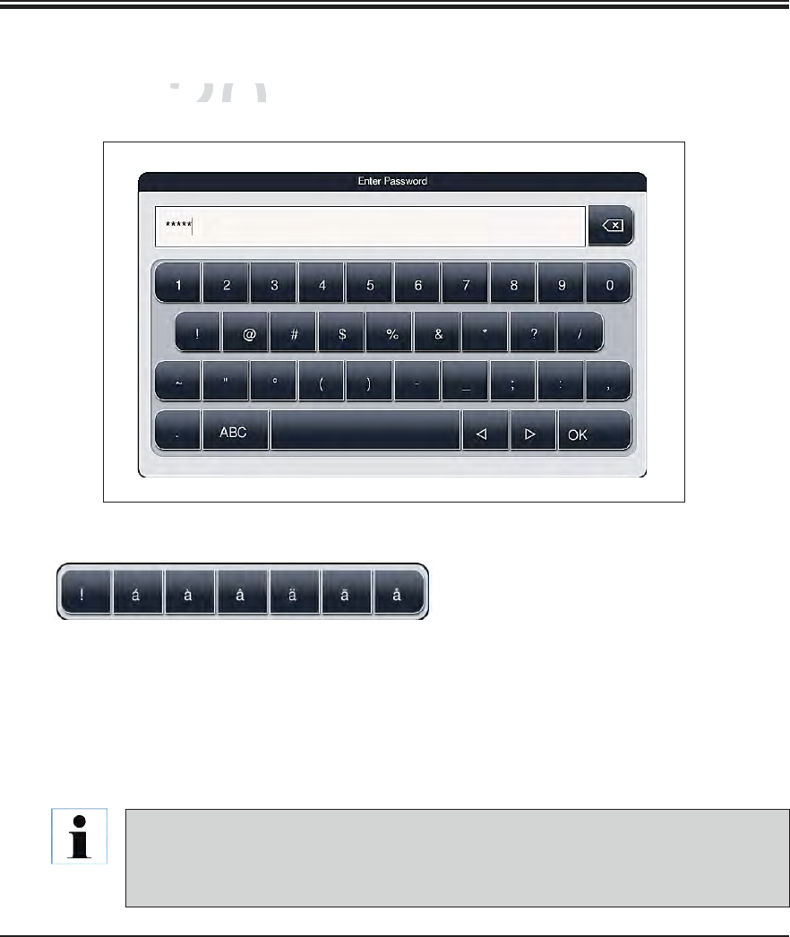
42 Instructions for Use V 0.5 RevC - 08/2014
5. Operation
5.5.1 The keyboard (continued)
To enter a special character or umlaut, etc. not included in the special character keyboard
(Fig. 22), hold the corresponding normal button on the keyboard.
Example: Holding the normal character "a" opens the selection options displayed in Fig. 23.
Select the required character from the new single-line keyboard by pressing it.
Fig. 23
Special character keyboard
Other special characters
Fig. 22
The following lengths are possible for passwords and designations:
Reagent names: max. 24 characters / reagent abbreviations: max. 10 characters
Program names: max. 24 characters / program abbreviations: max. 10 characters
Passwords: min. 4 to max. 10 characters
DRAFT
DRAFT
DRAFT
2014-08-21
c
ter keyboar
dcter keyboard
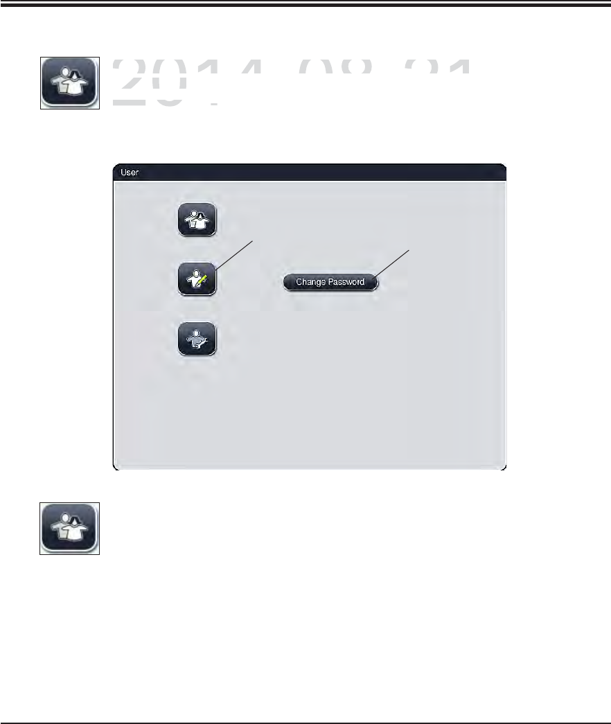
43
Leica HistoCore SPECTRA ST
5. Operation
Standard user:
The standard user does not need a password and can use the completely
configured instrument for all routine applications. It is not possible for this user
group to modify programs and settings.
Fig. 24
5.6 User settings
This menu can be used to configure the appropriate access level. A distinction is
made between
2
1
DRAFT
DRAFT
DRAFT
2014-08-21
T
his menu can be used to con
f
igure the appropriate acce
sThis menu can be used to configure the appropriate acces
made
be
tw
ee
n
made betwe
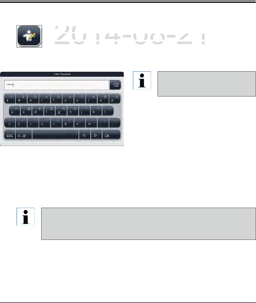
44 Instructions for Use V 0.5 RevC - 08/2014
5. Operation
Fig. 25
5.6 User settings (continued)
The password configured at the facto-
ry should be changed during the initial
setup.
To activate supervisor mode, proceed as follows:
Press the "Supervisor" button (1, Fig. 24).
Then, a keyboard (Fig. 25) is displayed which
can be used to enter the password.
The entry is finished by hitting "OK" and the
entered password is checked for validity.
The current user status is displayed with the
respective symbol in the status bar on the
top right.
To change the password, press the "Change password" (2, Fig. 24) button and enter the
old password. Then, enter the new password twice using the keyboard and confirm by
hitting "OK".
A password must have at least 4 characters and may have up to 10 characters.
Supervisor:
Supervisors have the same access options as the standard user, but can
also create programs and perform the instrument setup functions. Therefore,
supervisor access is password-protected.
DRAFT
DRAFT
DRAFT
2014-08-21
p
ervisor:
pervisor:
p
ervisors have the same access o
p
tions as the standard u
spervisors have the same access options as the standard us
o create programs and perform the instrument setup functio create programs and perform the instrument setup functi
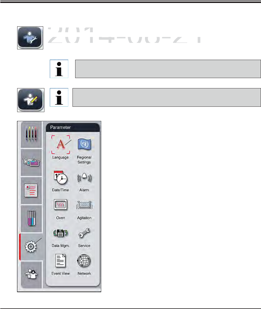
45
Leica HistoCore SPECTRA ST
5. Operation
Fig. 26
5.7 Basic settings
Service technician:
The service technician can access system files and carry out basic settings and
tests.
Access to this service menu is only possible for technicians trained by
Leica and certified for this instrument type.
Touching the gear symbol (1, Fig. 26) opens the "Parameters"
menu (Fig. 26). Basic instrument and software settings can
be configured in this menu.
Touching one of the symbols (e.g. 2, Fig. 26) selects it and
labels it with a red frame.
The respective settings window is displayed in the right
area of the screen.
The individual submenus are described below.
Changing the settings, for example when setting up the instrument for the
first time, is only possible in supervisor mode (see Chap. 5.6).
1
2
DRAFT
DRAFT
DRAFT
2014-08-21
S
ervice technician:
Service technicia
T
he service technician can access system files and carry
The service technician can access system files and carry
tt
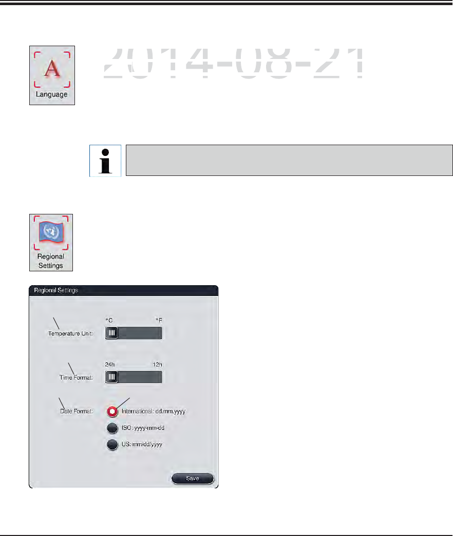
46 Instructions for Use V 0.5 RevC - 08/2014
5. Operation
5.7.1 Language settings
The language selection menu is displayed by pushing the symbol for the lan-
guage (2, Fig. 26). This menu contains an overview of all languages installed in
the instrument and allows the desired display language to be selected.
Select the desired language and confirm by hitting "Save".
The screen display and all messages and labels are displayed immediately in
the currently configured language.
A Leica service technician can add other languages using Import (see
Chap. 5.7.7).
Fig. 27
5.7.2 Country-specific settings
Basic display settings can be carried out in this menu.
Unit of temperature:
Configure the temperature unit (1, Fig. 27) in
Celsius or Fahrenheit. To do so, position the
slider to the desired unit.
Time format:
The time display (2, Fig. 27) can be changed
from a 24-hour display to a 12-hour display
(a.m. = morning/p.m. = afternoon) using the
slider.
Date format:
Configure the date display (3, Fig. 27) to in-
ternational, ISO or US format by pushing the
corresponding radio button next to the sample
format.
The activated setting is labeled by a red border
(4, Fig. 27)
Pushing the "Save" button saves the settings
2
4
3
1
DRAFT
DRAFT
DRAFT
2014-08-21
The language selection menu is displayed by pushing th
ehe language selection menu is displayed by pushing the
g
ua
g
e
guage
(
2
,Fig.
F
266
). This menu contains an overview of all la
This menu contains an overview of all la
the instrument and allows the desired display language tothe instrument and allows the desired display language to
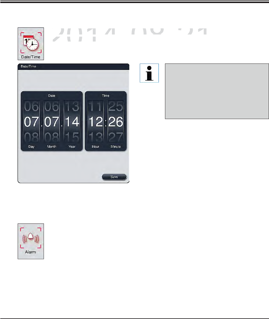
47
Leica HistoCore SPECTRA ST
5. Operation
5.7.3 Date and time
The current date and local time can be configured in this menu by rotating the
individual rollers.
Pushing the "Save" button saves the settings
In the 12-hour display, a.m. (morning)
and p.m. (evening) is displayed under
the hour digits to enable a correct set-
ting.
The time and date settings cannot de-
viate more than 24 hours from the sys-
tem time configured at the factory.
Fig. 28
This menu can be used to select the alarm and signal tones and adjust the vol-
ume. The current setting for alarm and signal tones is displayed after calling up
the menu.
5.7.4 Alarm and signal tones
DRAFT
DRAFT
DRAFT
2014-08-21
The current date and local time can be con
f
igured in thi
The current date and local time can be configured in thi
individual rollers
.individual rollers
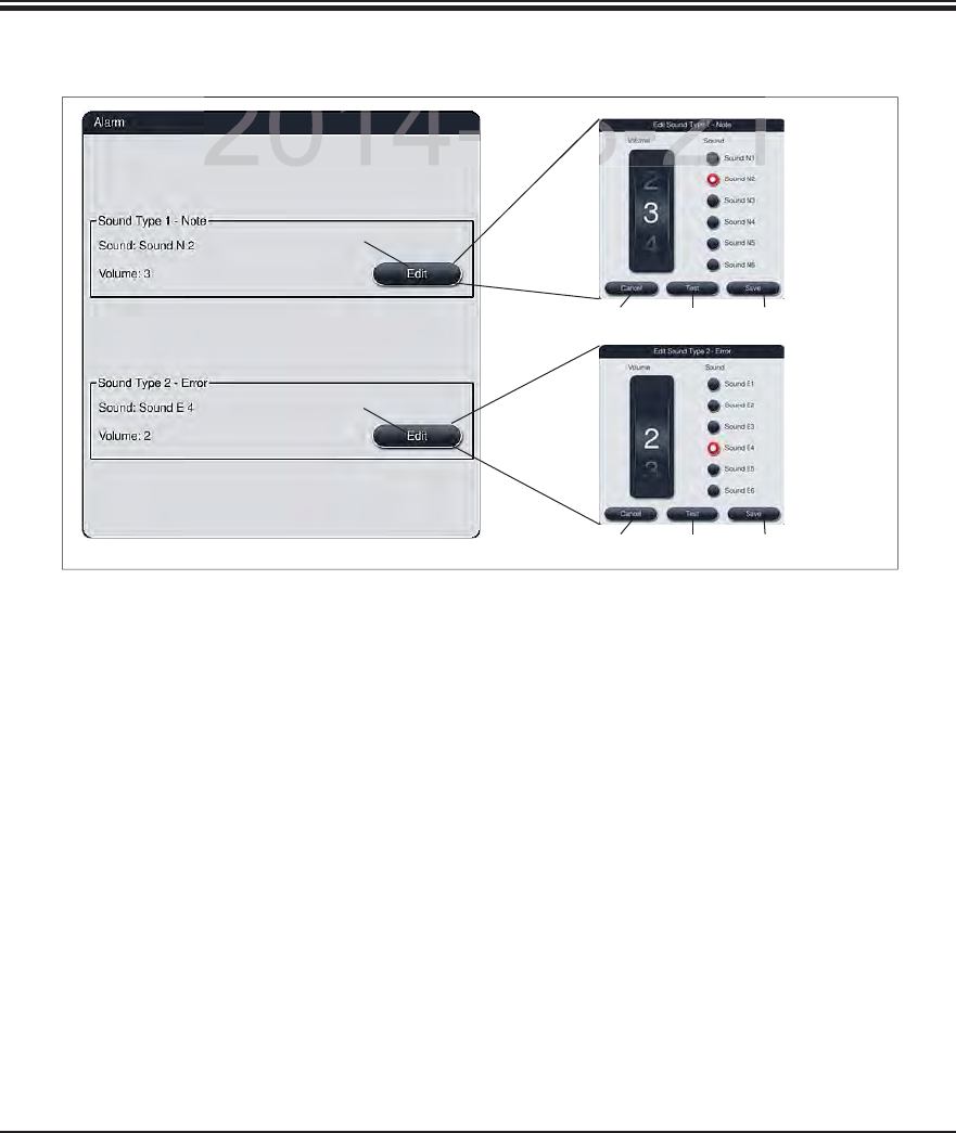
48 Instructions for Use V 0.5 RevC - 08/2014
5. Operation
5.7.4 Alarm and signal tones (continued)
Alarm type 1 - Note:
Signal tones are issued if a notification is displayed on the screen. You can select from a list of
6 sounds. To change the settings, press the "Edit" button (3, Fig. 29) .
Alarm type 2 - Error:
Alarm sounds are output if a warning or error message is displayed on the screen. This requires
immediate intervention from the user. You can select from a list of 6 sounds. To change the set-
tings, press the "Edit" button (4, Fig. 29).
The volume setting for alarm sounds is adjusted using the "Volume" roller. Six different
sounds are available for the alarm types. The "Test" button (7, Fig. 29) can be used to listen
to the respective sound.
Pressing the "Save" (8, Fig. 29) button saves the settings. The "Cancel" button (6, Fig. 29) is
used to close the selection window without applying the settings.
Fig. 29
1
2
3
4
768
768
DRAFT
DRAFT
DRAFT
2014-08-21
2014 08 21
08
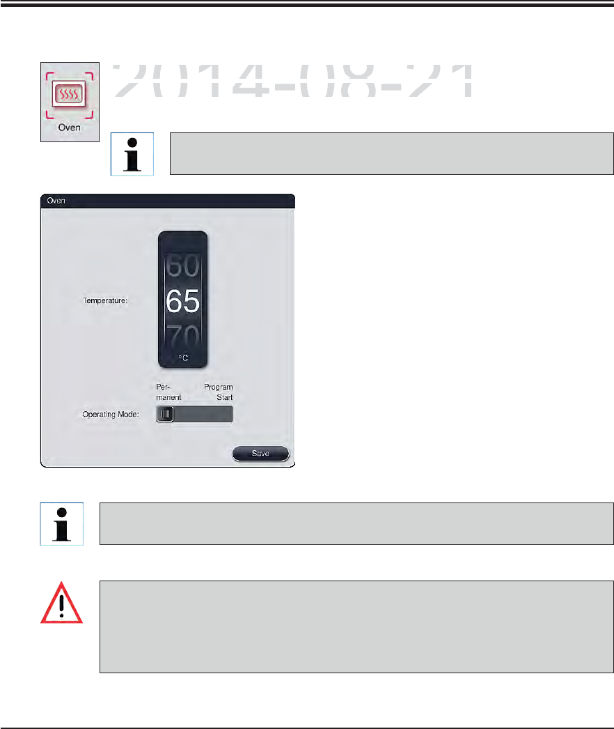
49
Leica HistoCore SPECTRA ST
5. Operation
The temperature of the oven and its operation mode can be configured in this menu.
The current oven settings are displayed after calling up the menu.
Temperature:
Rotating the roller can configure the target tem-
perature of the oven from 40 °C to 70 °C in 5 ° in-
crements.
Operation mode:
For the operation mode, you can choose be-
tween:
Heating the oven when starting a product
("Program start") or
Starting the oven when switching on the in-
strument ("Permanent").
The slider can be brought to the corresponding
position to change the settings.
Settings are saved by pressing the "Save"
button.
5.7.5 Setting the oven
The password-protected user mode "Supervisor" is required to save the changes. In the
simple user mode, the "Save" button is shown in gray and is inactive.
Validated Leica programs can be operated both with and without an oven step (see
Chap. 5.9.2). If an oven step is activated in a validated Leica program, the oven tem-
perature cannot be changed for all other programs and remains preset at 70 °C.
We recommend using "Permanent" as a setting to prevent repeated waiting times
caused by heating the oven.
Fig. 30
Changing the oven temperature will always have a potential impact on the
staining result.
DRAFT
DRAFT
DRAFT
2014-08-21
T
he temperature of the oven and its operation mode can be
cThe temperature of the oven and its operation mode can be c
T
he current oven settings are displayed a
f
ter calling up the
The current oven settings are displayed after calling up the
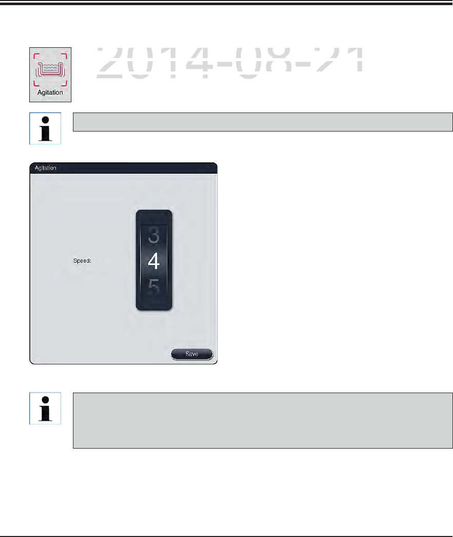
50 Instructions for Use V 0.5 RevC - 08/2014
5. Operation
5.7.6 Movement speed - up/down movement (agitation)
This menu is used to configure the movement speed of the retaining frame for
slide racks. The slide rack clips are on the retaining frame which moves back and
forth in the staining process (agitation).
The current setting is displayed after calling up the menu.
Speed:
Rotating the "Speed" roller can be used to
configure the agitation frequency in 5 steps (0=
agitation disabled, 5= highest speed). Higher
values mean a higher agitation frequency.
Settings are saved by pressing the "Save"
button.
The agitation speed for user-defined programs can only be changed if no validated Lei-
ca program is active. In this case, the roller is displayed in black and active. Agitation is
the default for validated Leica programs and cannot be changed. The roller is grayed out
and inactive.
Fig. 31
Agitation helps stir the added reagents during ongoing staining processes.
DRAFT
DRAFT
DRAFT
2014-08-21
is menu is used to configure the movement speed of the
is menu is used to configure the movement speed of the
d
e racks. The slide rack clips are on the retaining
f
rame wh
de racks. The slide rack clips are on the retaining frame wh
rth in the staining process (agitation)rth in the staining process (agitation
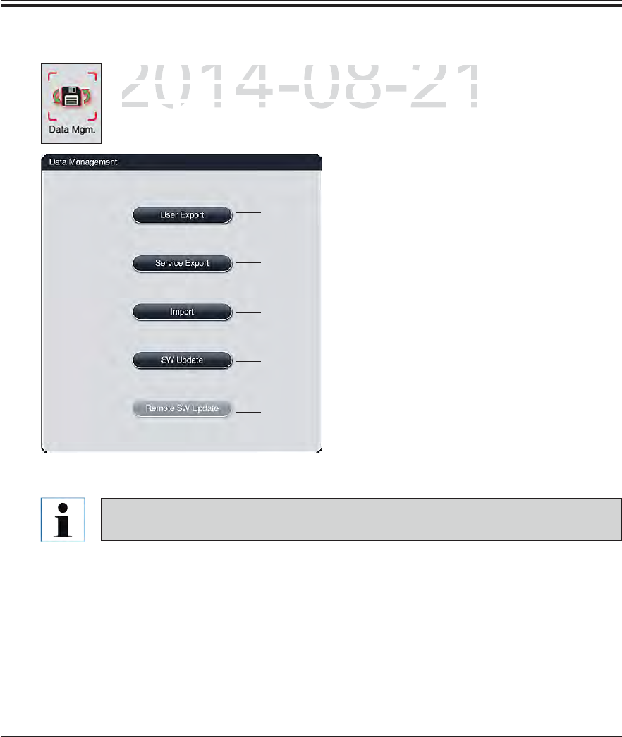
51
Leica HistoCore SPECTRA ST
5. Operation
5.7.7 Data management
In this menu, the data, settings and event logs (log files) can be exported. A USB
memory stick connected to one of the USB sockets on the front side of the instru-
ment (7a, Fig. 2) is required for all exports and imports (except for remote software
updates).
Fig. 32
1
2
3
4
5
User export (1, Fig. 32)
The "User export" function is used to save
various information on a connected USB
memory stick (see 7a, Fig. 2). The following
files are transferred:
All defined programs and reagent lists as
a packed and encrypted Zip file
Event log (of the last 30 working days)
RMS information in CSV format
User-defined programs and the reagent list
can be transfered to another SPECTRA ST by
the "Import" function (3, Fig. 32).
After successfully setting up the instrument, we recommend exporting the data to be
able to access it if the instrument has to be set up again.
DRAFT
DRAFT
DRAFT
2014-08-21
In this menu, the data, settin
g
s and event lo
g
s (lo
g
files)
cthis menu, the data, settings and event logs (log files) c
memory stick connected to one of the U
S
B sockets on the
memory stick connected to one of the USB sockets on the
ment (ment
7a7a
FigF
2
) is required for all exports and imports (exc) is required for all exports and imports (exc
52 Instructions for Use V 0.5 RevC - 08/2014
5. Operation
This function enables the data import of the encrypted program and reagent list, additional
validated Leica programs and additional language packages from a connected USB memory
stick. This data can also be used to equip another SPECTRA ST with the same data using the
Export/Import function.
To do this, insert the USB memory stick with the previously exported data into one of the
USB sockets on the front side of the instrument.
Then, select the "Import" function. The data is scanned.
When importing data from a USB memory stick, all programs and reagents previously
located on the instrument are overwritten.
The password-protected user mode "Supervisor" is required for importing.
5.7.7 Data management (continued)
Import (3, Fig. 32)
Service export (2, Fig. 32)
Along with the files named below, this function also saves technical information for error log
analysis and is required for technical instrument diagnostics.
The data is stored encrypted and cannot be read out on a PC.
Two files are also stored that are merged into a zip file. These files are packed in a ZIP folder
unencrypted. They can be read out and used by a service technician authorized by Leica:
Error log (of the last 30 days)
Content of the ZIP folder:
1. Run-Log-Datei mit allen Statusmeldungen in der eingestellten Sprache
2. Information from the reagent management system (RMS), in CSV format.
DRAFT
DRAFT
DRAFT
2014-08-21
t
((
2,2
Fi
g.
Fig
323
)
files named below, this function also saves technical info
rfiles named below, this function also saves technical infor
i d f t h i l i t t di tiidf t hi li t tdi
53
Leica HistoCore SPECTRA ST
5. Operation
5.7.7 Data management (continued)
Software update (4, Fig. 32)
Software updates and additional language packages may only be run by a service technician
authorized by Leica, e.g. for installing.
Lab-specific settings are not deleted when updating the software for the SPECTRA ST.
Remote software update (5, Fig. 32)
This function makes it possible to update the software using a connected network. To do so,
the instrument must be integrated into the Leica Remote Care maintenance and diagnostic
system.
The new software version is loaded automatically as soon as it is available for this instru-
ment. Once the loading procedure has concluded, the button (5, Fig. 32) is shown in black
and is activated.
Pressing the "Remote software update" button starts the automatic update process when
the instrument is idle.
The user will be notified about an available software update via a message.
The SPECTRA ST software is updated; lab-specific settings are not deleted.
DRAFT
DRAFT
DRAFT
2014-08-21
p
date
pdate
(
4
,
4,
Fi
g.
g.
322
))
p
dates and additional language packages may only be run
pdates and additional language packages may only be run
b L i f i t llib L i f i t lli
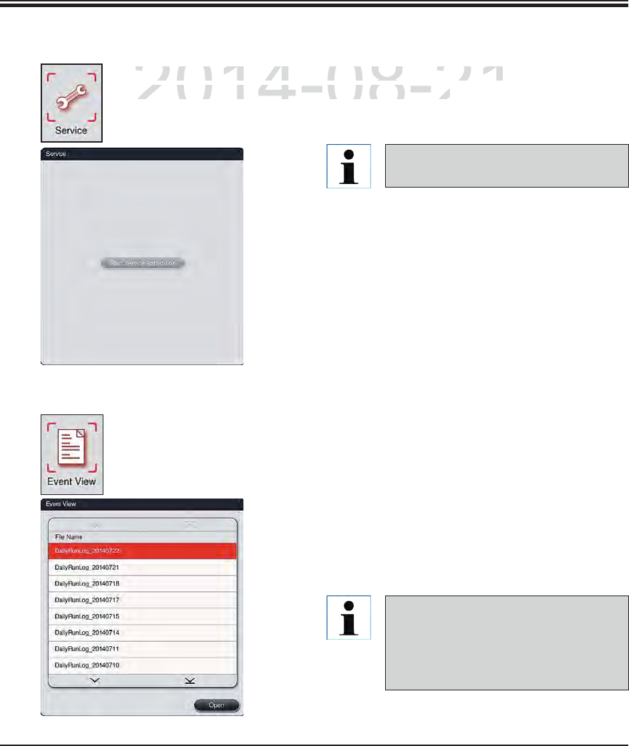
54 Instructions for Use V 0.5 RevC - 08/2014
5.7.8 Service access
5. Operation
This menu gives Leica authorized service technicians access to technical func-
tions for diagnostics and repairs to the SPECTRA ST.
Fig. 33
Access to the service software is
locked for all other user groups.
5.7.9 Event view
A separate log file is created for each day that the instrument was switched on.
This file can be called up by selecting the "DailyRunLog" file in the event view.
Fig. 34
In the event view, an event log can be selected
from a list of available logs and called up by
hitting the "Open" button.
The file name is supplemented by the
respective creation date in ISO format,
which makes it easier to organize. The
file is created in the configured lan-
guage.
DRAFT
DRAFT
DRAFT
2014-08-21
h
is menu gives Leica authorized service technicians acce
shis menu gives Leica authorized service technicians acces
o
ns for diagnostics and repairs to the
S
PE
C
TRA
S
T.
ns for diagnostics and repairs to the SPECTRA ST.
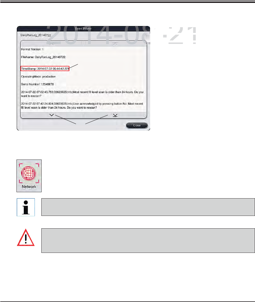
55
Leica HistoCore SPECTRA ST
5. Operation
All event entries begin with a time
stamp (1, Fig. 37), which indicates
the date and time when the entry
was created.
You can scroll up and down in the list
and the log file using the arrow keys
(2, Fig. 35).
Fig. 35
5.7.9 Event view (continued)
1
2
5.7.10 Network settings
This menu allows you to set the network parameters for connecting to a network.
Data can be transferred to a lab information system (LIS) via this network.
Leica service organizations can access the instrument's technical data via a service
network (Remote Care) for diagnostic purposes and install software updates.
The device may only be connected to an available network, for example during the ini-
tial installation, by Leica-authorized service technician in cooperation with the local IT
department.
DRAFT
DRAFT
DRAFT
2014-08-21
All event en
tl event ent
stamp
(stamp
1
,
Figig
the date ande date and
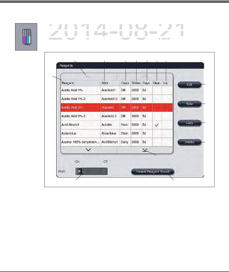
56 Instructions for Use V 0.5 RevC - 08/2014
5. Operation
5.8 Reagent list
Fig. 36
1Reagent name 8Edit selected reagent
2Abbreviation of the reagent name 9Create a new reagent
3Process class 10 Copy selected reagent
4Maximum number of slides 11 Delete selected reagent
5Maximum period of use 12 Edit settings of heated cuvettes for the se-
lected reagent
6Heated reagent cuvette yes/no 13 Activate/deactivate RMS
7Insert for special dye yes/no 14 You can scroll through the reagent list using
the arrow keys.
4 765
8
12
10
9
11
23
1
13
14
14
Open the reagent list by pressing the adjacent button. This displays all defined re-
agents in alphabetical order. Furthermore, a suitable reagent of a heated reagent
cuvette (optional) (12, Fig. 36) can be assigned (Fig. 37).
DRAFT
DRAFT
DRAFT
2014-08-21
p
en the reagent list by pressing the adjacent button. This di
spen the reagent list by pressing the adjacent button. This dis
g
ents in alphabetical order. Furthermore, a suitable reagent
ents in alphabetical order. Furthermore, a suitable reagent
uvette (optional) (uvette (optional) (
121
Fig
363
) can be assigned (be assigne
Figg
3737
))
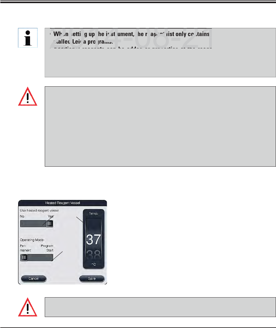
57
Leica HistoCore SPECTRA ST
5. Operation
When setting up the instrument, the reagent list only contains reagents from the prein-
stalled Leica programs.
Additional reagents can be added or properties of the reagents can be changed as
needed in the reagent list.
Creating or editing a reagent requires "Supervisor" mode. The "User" status only al-
lows reagent data to be displayed.
The "RMS: On – Off" (13, Fig. 36) allows the reagent management system = RMS to be
switched on or off. This system controls the reagent consumption monitoring. We al-
ways recommend keeping the RMS switched on and following the instructions for re-
placing a reagent (see Chap. 6.3). It is not possible to switch off reagent monitoring
for the Leica staining kit reagents.
Failure to adhere to the specified intervals can have a negative effect on the staining
quality. The RMS only works reliably if the data has been stored by the user correctly
in advance.
The manufacturer assumes no liability for the staining results in case of errors when
entering the reagent data. The user cannot edit Leica-validated reagents.
5.8 Reagent list (continued)
Select the desired reagent in the reagent list by touch-
ing it.
Press the "Heated reagent station" (12, Fig. 36) button
to open the settings menu (Fig. 37).
Set the slider (1, Fig. 37) to "Yes" to activate the heated
reagent station.
Select the operation mode (2, Fig. 37).
Configure the temperature using the roller (3, Fig. 37).
Save the entries with the "Save" button or close the
menu with the "Cancel" button to close the menu without
applying the entries.
5.8.1 Define heated reagent (optional)
2
3
1
Reagents like xylene, xylene substitute, alcohols and solutions containing alcohol may
not be defined as a heated reagent!
Fig. 37
DRAFT
DRAFT
DRAFT
When setting up the instrument, the reagent list only contains r
stalled Leica programs.
Additional reagents can be added or properties of the reage
2014 08 21
2014 08 21
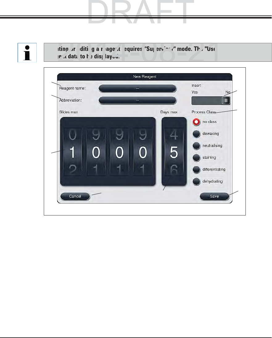
58 Instructions for Use V 0.5 RevC - 08/2014
To add a new reagent to the reagent list, press the "New" (see 9, Fig. 36) button.
It opens the entry window for the new reagent to be created (see Fig. 38).
The following parameters can be entered:
Reagent name
Push the "Reagent name" (1, Fig. 38) button and enter a unique reagent name that has not yet
been used using the onscreen keyboard. You can enter up to 24 characters (including spaces).
Abbreviation
The "Abbreviation" (2, Fig. 38) button can be pressed to enter a unique reagent name that has
not yet been used using the onscreen keyboard (maximum 10 characters, including spaces).
Creating or editing a reagent requires "Supervisor" mode. The "User" status only allows
reagent data to be displayed.
5.8.2 Creating a new reagent
Fig. 38
4
25
3
6
1
7
8
5. Operation
DRAFT
DRAFT
2014-08-21
g or editing a reagent requires "Supervisor" mode. The "User
ent data to be displayed.
2014-08-21
59
Leica HistoCore SPECTRA ST
Max. specimen slides:
The roller (3, Fig. 38) is used to configure the maximum number of slides that can be processed
with this reagent before a reagent change is requested. By rotating the rollers, values between
1 through 3999 are permitted.
Max. days:
The maximum number of days (4, Fig. 38) that the reagent can remain in the instrument is con-
figured by rotating the roller. Values from 1 through 99 are permitted when entering figures.
Holder for 5 specimen slides:
If a reagent cuvette is equipped with an element for special staining to enable a smaller re-
agent volume, using the slide rack for 5 slides only is possible in this cuvette. Then, you must
set the slide switch to "Yes".
Using a slide rack for 30 slides in this cuvette is now disabled.
5.8.2 Creating a new reagent (continued)
Using the element for special staining in one or more reagent cuvette(s) requires
switching to the "Yes" position. If the switch is not set correctly for the affected reagent
cuvette(s), it can cause a slide rack for 30 slides to be used in this cuvette, which inevi-
tably leads to a serious equipment failure with possible specimen loss.
5. Operation
Process class:
Assigning the reagents to process classes (6, Fig. 38) is required since, along with the prioriti-
zation of programs, it is essential for calculating the individual positions of the bathlayout (see
Chap. 5.8.2).
Save the entries with the "Save" (7, Fig. 38) button or close the entry window without applying
the entry using the "Cancel" (8, Fig. 38) button.
Subsequently changing a process class is no longer possible after the initial save. The
reagent can only be deleted and re-created or copied and then changed.
DRAFT
DRAFT
DRAFT
2014-08-21
m
en s
lid
es
:men slides:
3
,
,
Fi
g.
Fig.
388
)
is used to configure the maximum number of slide
s) is used to configure the maximum number of slides
t b f t h i t d B t ti tht b f t h i t d B t ti th
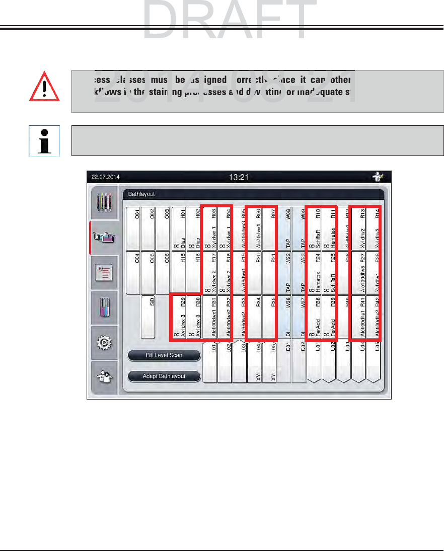
60 Instructions for Use V 0.5 RevC - 08/2014
5. Operation
Fig. 39
1223
1The preferred zone for dewaxing reagents is the left side of the bathlayout.
2The preferred zone for staining solutions or differentiating solutions are the two rows to
the left and right of the rinsing water stations.
3The preferred zone for draining reagents is the right side of the bathlayout.
5.8.3 Process classes
Process classes must be assigned correctly since it can otherwise cause delayed
workflows in the staining processes and deviating or inadequate staining results.
The reagent process classes of preinstalled Leica programs are already defined and
cannot be changed.
DRAFT
DRAFT
2014 08 21
s classes must be assigned correctly since it can otherw
kflows in the staining processes and deviating or inadequate sta
2014 08 21

61
Leica HistoCore SPECTRA ST
5. Operation
5.8.3 Process classes (continued)
Process class Description Example of reagents
Dewaxing
(Dewaxing)
Solvents that remove the paraffin and,
following the paraffin removal, the
subsequent graded alcohol series, at the
beginning of a staining program.
Xylene
Xylene substitute
Graded alcohol se-
ries: 100 %, 95 %, 70 %
alcohol
Neutralizing
(Neutralizing)
Reagents that have little or no effect on the
stain application or the stain development
and that have a roughly neutral pH value.
Example: Aqua dest. step before a stain-
ing step.
Aqua dest. (demin-
eralized)/fresh water
(not in rinsing water
stations!)
Thinning with aqua
dest.
Aqueous alcoholic
solutions (e.g. 70 %
ethanol)
Staining
(Staining)
Staining solutions
Wood stains
Oxidizing agents (e.g. Periodic acid of the
PAS dye)
All staining solutions
Wood stains and oxi-
dizing agents
Differentiating
(Differentiating)
Reagents that remove excess color from
the product.
Reagents that are required for the stain
development or a color change.
Low pH value:
HCL solution (alcoholic
or aqueous)
Acetic acid
High pH value:
Ammonia water
Scott's tap water
Blueing Solution
Blue Buffer
Lithium Carbonate
No two successive rinsing water steps can be programmed (rinsing water step for aqua
dest. or vice versa). If the sequence of the program steps is to occur in this way, one of
the steps has to be defined as a reagent assigned to a process class (e.g. neutralizing).
DRAFT
DRAFT
DRAFT
2014 08 21
No two successive rinsing water steps can be programmed (rins
est. or vice versa). If the sequence of the program steps is to o
he steps has to be defined as a reagent assigned to a process cl
2014 08 21
62 Instructions for Use V 0.5 RevC - 08/2014
5. Operation
5.8.3 Process classes (continued)
Process class Description Example of reagents
Dehydrating
(Dehydrating)
Reagents of the ascending alcohol series,
at the end of a staining program.
Subsequent solvent steps (xylene or xy-
lene substitute), at the end of a staining
program, for preparing the coverslipping
operation.
Dehydration:
Ascending alcohol se-
ries: 70 %, 95 %, 100 %
alcohol
Preparing the coverslip-
ping operation:
Xylene
Xylene substitute
No class
(no class)
Reagents that do not require any special assignment in the bathlayout
(see information below).
The following must be observed for preparing the coverslipping operation:
The solvent used at the end of the program and in the following coverslipping process
must be compatible with the mountant.
The correct assignment of the process classes is necessary so that the optimal bathlay-
out can be calculated and long transport paths and times can be avoided.
Basic rules of automatic creation of the bathlayout include:
The transfer from the left cuvette field to the right cuvette field should occur via a
rinsing water station whenever possible.
Programs that do not contain a rinsing water station as a step use the dry transfer sta-
tion for this transfer.
Staining reagents that require a subsequent rinsing water step are positioned adja-
cent to the water flow cuvettes (Zone 2, Fig. 39).
Reagents for which "No class" has been assigned as a process class are set at any
position during the automatic creation of the bathlayout.
Instead of the "No class" assignment, we recommend assigning these reagents to ei-
ther the "Differentiating" or "Neutralizing" project class so that adjacent stations in
the bathlayout can be taken into account for series.
DRAFT
DRAFT
DRAFT
2014-08-21
Description
Examp
Rea
g
ents of the ascendin
g
alcohol series
,Reagents of the ascending alcohol series,
D
e
hydDehyd
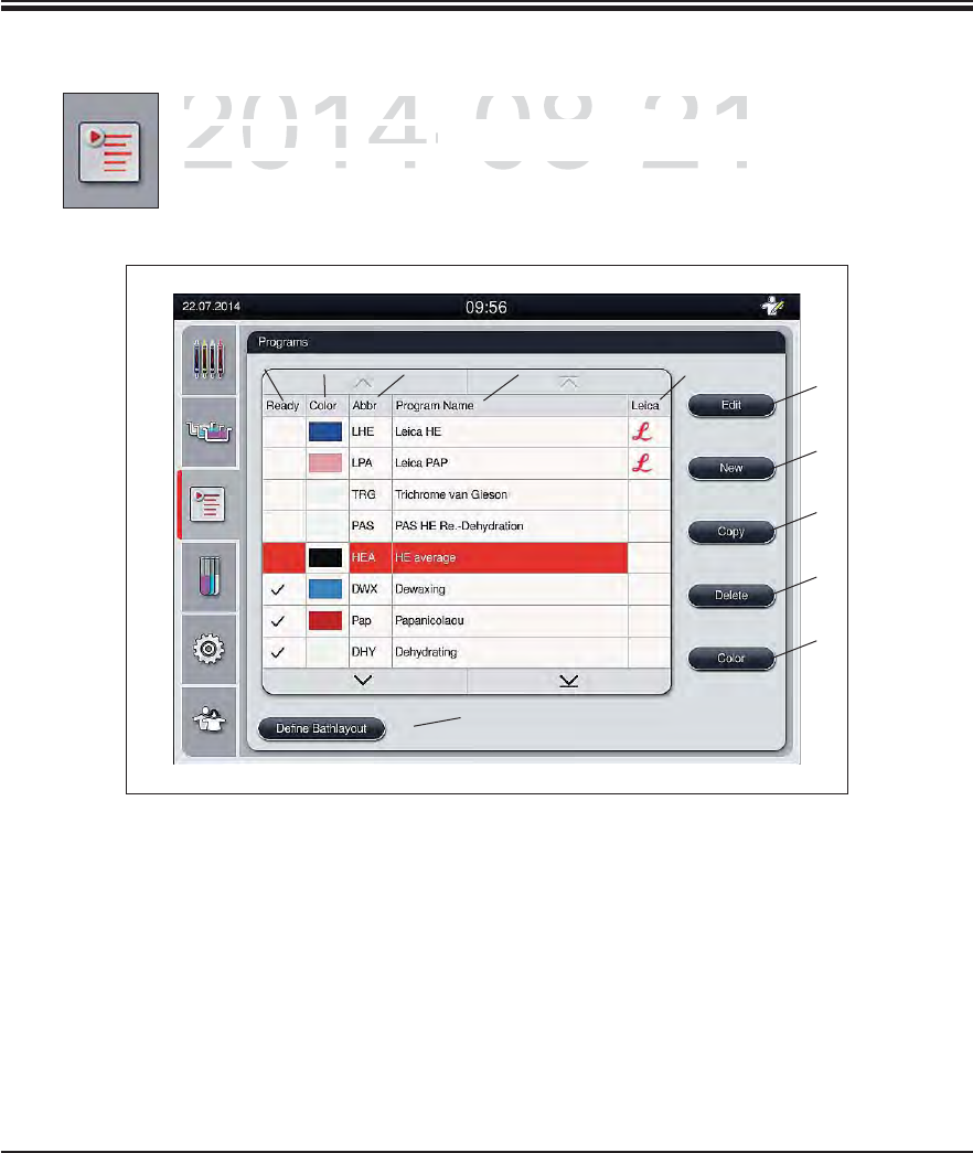
63
Leica HistoCore SPECTRA ST
5. Operation
5.9 Staining program
The list of the staining programs installed on the SPECTRA ST is opened by push-
ing the "Programs" button.
A distinction is made between two types of staining programs:
Leica staining programs (preinstalled) (see Chap. 5.9.2)
User-defined staining programs (see Chap. 5.9.4)
6
7
10
8
9
11
432
15
1The program is taken into account
in the current bathlayout.
7Create a new program
2Assigned program color 8Copy selected program
3Program abbreviation 9Delete selected program
4Program name 10 Assign a color to the selected program
5Preinstalled Leica program 11 Define bathlayout
6Edit program
Fig. 39
DRAFT
DRAFT
DRAFT
2014-08-21
The list of the staining programs installed on the SPECTR
AThe list of the staining programs installed on the SPECTRA
ing the
ing the
"Programs"
rogram
b
utton
.button.
A distinction is made between two types of staining prograA distinction is made between two types of staining progra
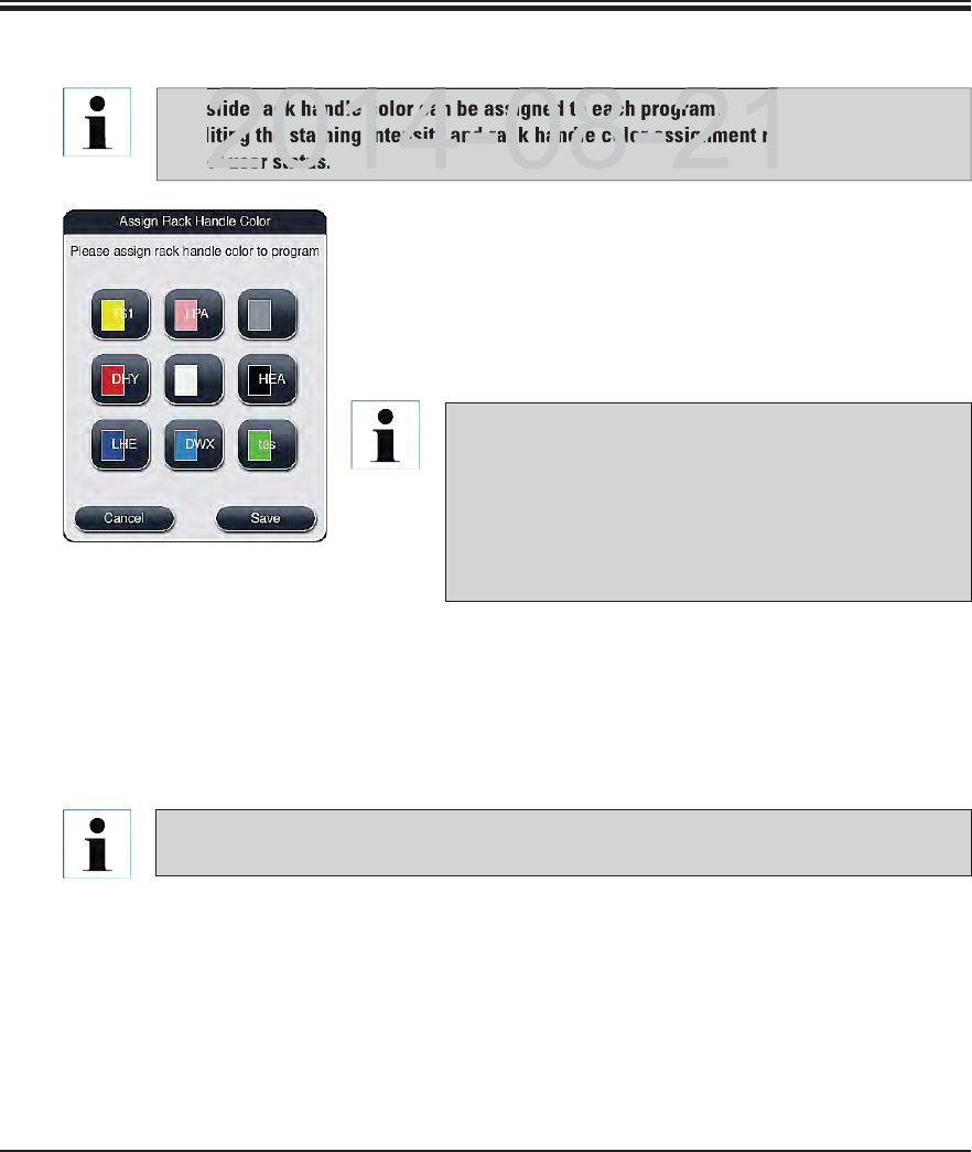
64 Instructions for Use V 0.5 RevC - 08/2014
5. Operation
Fig. 41
5.9.1 Staining program - general settings
In the program list (Fig. 40), select the program that is to be
assigned a slide rack handle color by touching the correspond-
ing entry.
Pressing the "Color" (10, Fig. 40) button is used to display a
selection field (Fig. 41) that allows assigning the slide rack
handle color to the selected program.
A slide rack handle color can be assigned to each program.
Editing the staining intensity and rack handle color assignment requires the "Supervi-
sor" user status.
All available colors are displayed in Fig. 41. If an ab-
breviation is entered in the color field, this color has
already been assigned to a program.
If an already assigned color is selected, a dialog box
appears with a security prompt indicating that the
existing assignment will be undone. This can be con-
firmed with "OK" or aborted with "Cancel".
Select a color that has not been assigned previously.
"Save" is used to assign the color and close the dialog.
"Cancel" is used to close the dialog without applying the changes.
The color white is a wildcard color. When selecting a white clip for the slide rack, a
program selection window opens in which a color has to be assigned to the white clip.
DRAFT
DRAFT
DRAFT
2014 08 21
slide rack handle color can be assigned to each program.
ting the staining intensity and rack handle color assignment re
or" user status
2014 08 21
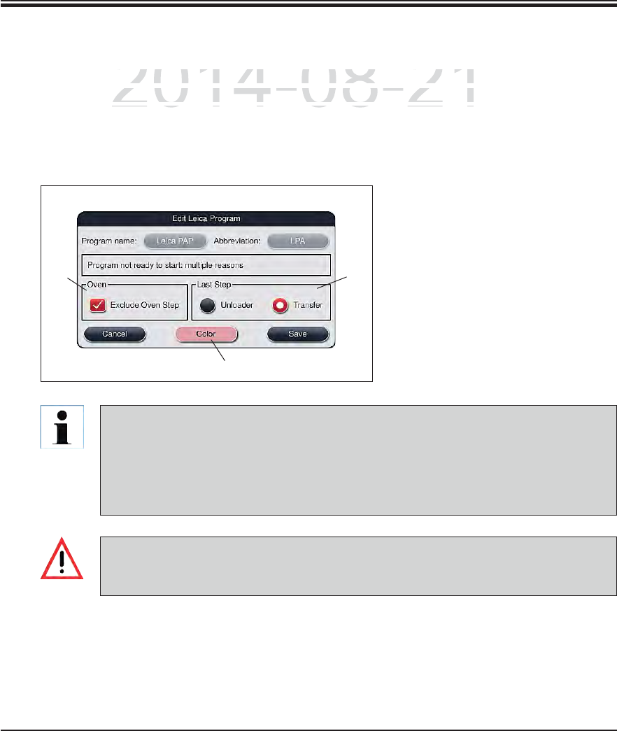
65
Leica HistoCore SPECTRA ST
5. Operation
5.9.2 Leica staining programs (preinstalled)
Leica staining programs require the use of the specific Leica reagent kit.
The individual program steps of the Leica staining program cannot be shown, edited,
copied or deleted.
If the Leica staining program provides for it, the oven step can be enabled or disabled.
Likewise, the last program step for unloading the racks into the output drawer or for
transferring them to the SPECTRA CV robotic coverslipper can be programmed.
Leica staining programs are preinstalled at the factory and have had their function and stain-
ing properties tested. They ensure a uniform staining quality for a specified number of slides.
Leica staining programs are labeled in the last column with a cursive Leica "L" (5, Fig. 40).
Fig. 42
12
3
If a paraffin removal step is not provided as the first step for the Leica staining program,
then the oven step (see 1, Fig. 42) must not be enabled, as otherwise the specimens
could be destroyed!
DRAFT
DRAFT
DRAFT
2014-08-21
a
ining programs are preinstalled at the factory and have had
tning programs are preinstalled at the factory and have had t
e
rties tested. They ensure a uniform staining quality for a sp
eerties tested. They ensure a uniform staining quality for a spe
ii lbldi h l l ih iii lbldi h l l ih i
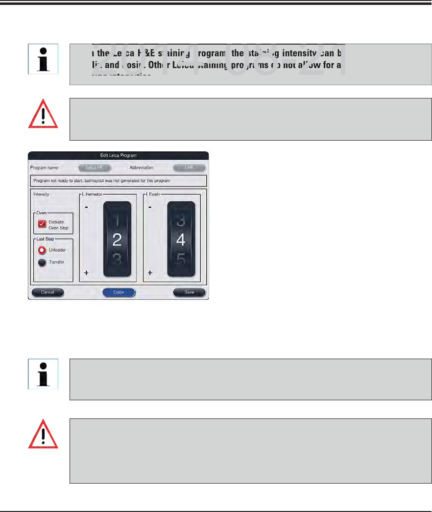
66 Instructions for Use V 0.5 RevC - 08/2014
5. Operation
5.9.3 Adapting the Leica H&E staining program
If "Edit" (6, Fig. 40) is selected in the program list,
a dialog opens that enables the staining intensity
to be set.
The staining intensity values can be set by
turning the rollers. Smaller numerical values
cause a lower staining intensity; higher numer-
ical values cause a larger staining intensity.
A rack handle color can be assigned to the
program (see Chap. 5.9.1).
Use "Save" to save the settings and close the
dialog.
Use "Cancel" to close the dialog without sav-
ing changes.
Fig. 43
With the Leica H&E staining program, the staining intensity can be adjusted for hema-
toxylin and eosin. Other Leica staining programs do not allow for any adjustments to the
staining intensities.
After the user adjusts the staining intensity, the staining result has to be checked with
a specimen cycle (trial sections) before the settings are used for patient specimens for
clinical diagnostics.
Creating a new staining program or editing an existing staining program requires the
"Supervisor" user status.
The "User" status only allows program steps to be displayed.
5.9.4 User-defined staining programs
Leica can provide neither testing nor a warranty for user-defined programs.
Testing of these staining programs, with the respectively used reagents, must be car-
ried out in the lab by the user. To do so, the staining result has to be checked with a
specimen cycle (trial sections) before the program is used for patient specimens for
clinical diagnostics.
DRAFT
DRAFT
DRAFT
2014 08 21
e Leica H&E staining program, the staining intensity can be
lin and eosin. Other Leica staining programs do not allow for an
ning intensiti
2014 08 21
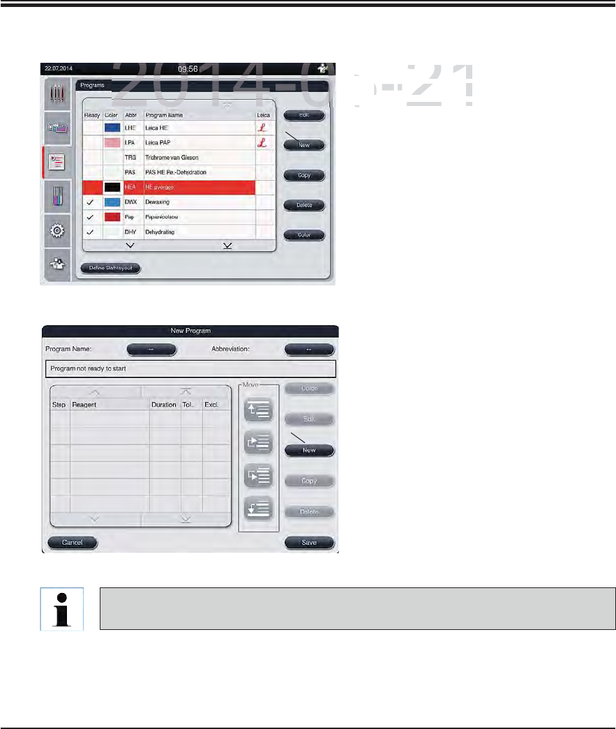
67
Leica HistoCore SPECTRA ST
5. Operation
5.9.5 Creating a new staining program
In the list view of the programs, press
the "New" button (1, Fig. 44).
A new program window opens.
Fig. 44
1
Two empty buttons are shown in the upper
area of this window. They are intended for
the program name and its abbreviation.
Press the "--" button behind the "Pro-
gram Name" designation.
An input mask with keyboard appears.
Enter the program name.
Press the "OK" button to finish.
Proceed as described above to enter the
"Abbreviation".
Fig. 45
1
To create a new staining program, multiple program steps are added to the program in
sequence.
DRAFT
DRAFT
DRAFT
2014-08-21
I
n the list view
e list view
t
h
e
the
"N
ew
""New"
butto
o
A new programw program w
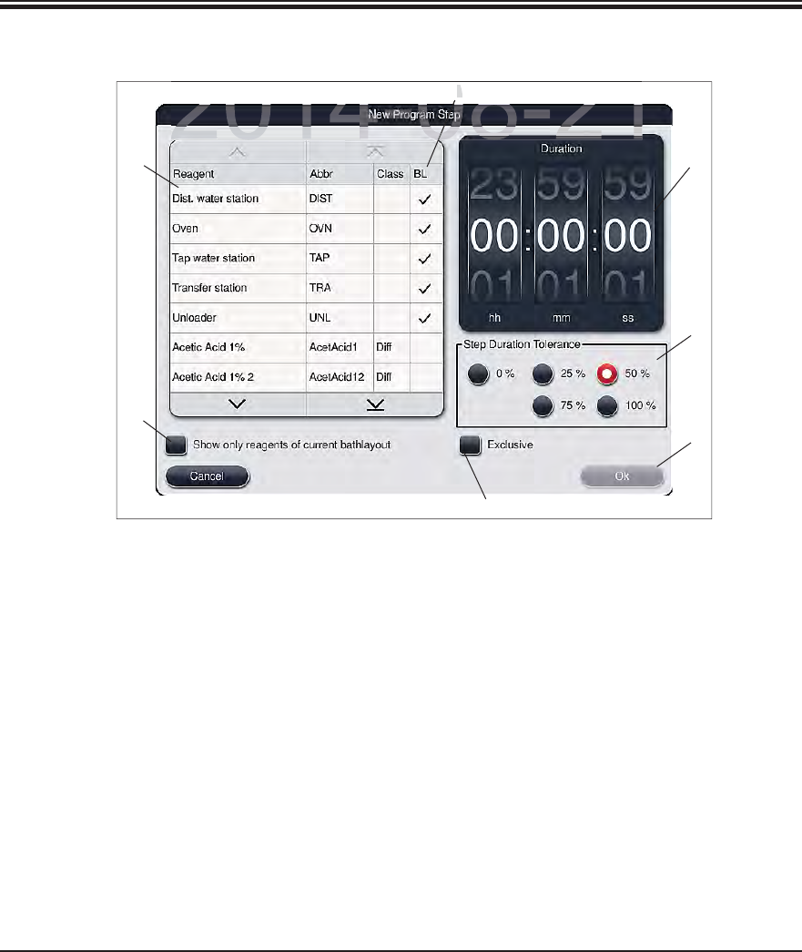
68 Instructions for Use V 0.5 RevC - 08/2014
5. Operation
5.9.5 Creating a new staining program (continued)
Fig. 46
After a new program has been created, press the "New" button (see 1, Fig. 45).
A window opens for defining the program step (Fig. 46).
The reagents already predefined by the user are listed in the area on the left (1, Fig. 46). This
is marked by selecting a reagent.
The reaction time (hh/mm/ss) of the specimens in the reagent is defined in the area on the
right by turning the rollers (2, Fig. 46).
The valid setting range goes from 1 second up to 23 hours 59 minutes and 59 seconds.
The permitted "Tolerance" (3, Fig. 46) of the step is set under this. If an accurate program step
is needed that does not allow chronological expansion of the specified time, the tolerance
0
% must be selected. The tolerance can be selected in 25 % increments up to a maximum
expansion of 100 %, i.e. the instrument can extend the step to twice the length of the con-
figured time, if needed.
12
3
5
4
6
7
DRAFT
DRAFT
DRAFT
2014 08 21
2014 08 21
4
4
0
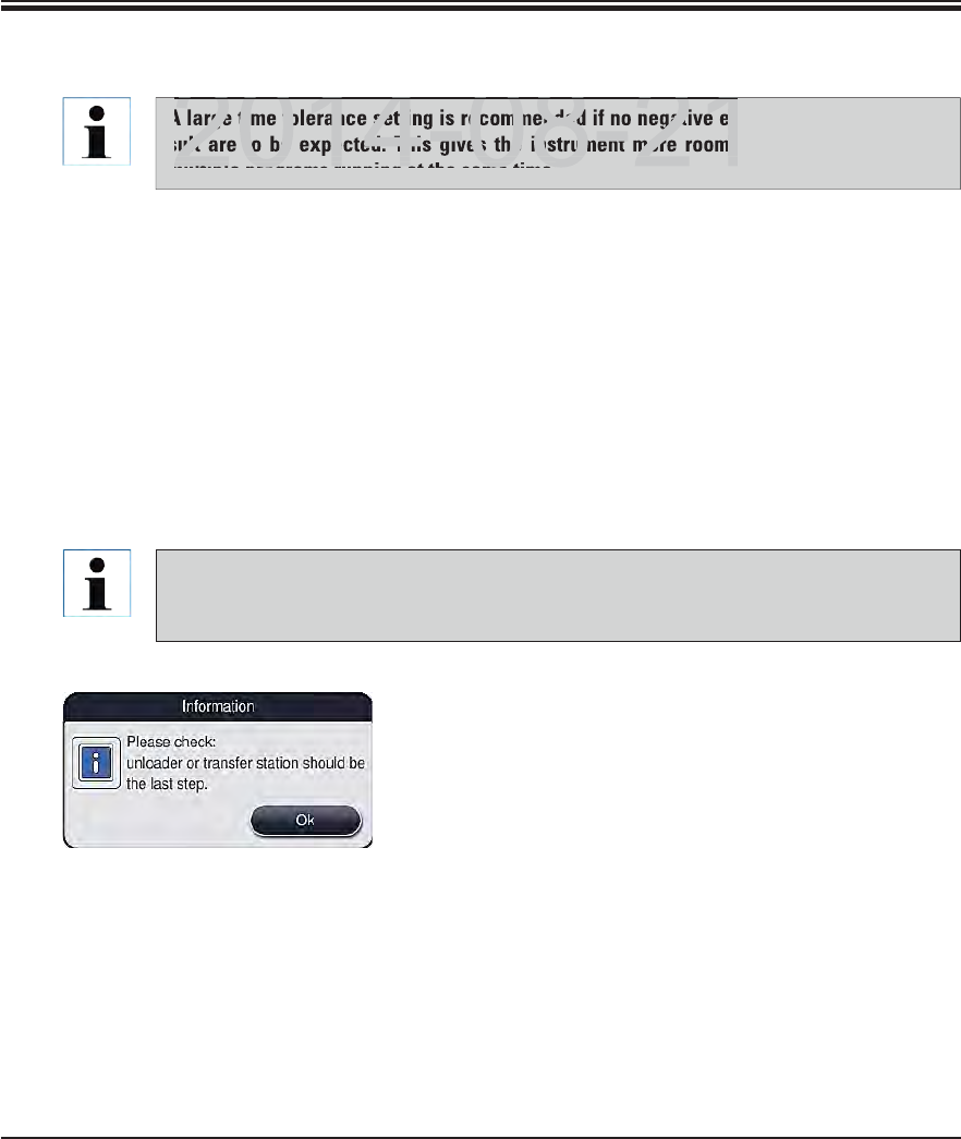
69
Leica HistoCore SPECTRA ST
5. Operation
5.9.6 Inserting a new program step (continued)
A program must always be concluded with a final target station step. Either the output
drawer (Unloader UNL) or the transfer station (Transfer Station TRA – only in worksta-
tion mode) can be selected for transfer to the SPECTRA CV robotic coverslipper
A warning message indicates that saving the program
without defining the target station as the last step is not
possible.
Fig. 47
A large time tolerance setting is recommended if no negative effects on the staining re-
sult are to be expected. This gives the instrument more room to synchronize steps of
multiple programs running at the same time.
If a check mark is in the "BL" column (4, Fig. 46), it means that this reagent is already inte-
grated into the bathlayout.
To limit the display to reagents that are already actively used in the bathlayout, enable the
radio button "Show only reagents of current bathlayout" (5, Fig. 46).
If the "Exclusive" box (6, Fig. 46) is enabled, the selected reagent can be used only for the
created program and no other program is available for selection.
The program step entry is completed with "OK" (7, Fig. 46).
Depending on need, other program steps can be added in the same way until all staining
process steps are illustrated in the program.
DRAFT
DRAFT
DRAFT
2014 08 21
rge time tolerance setting is recommended if no negative eff
ult are to be expected. This gives the instrument more room t
multiple programs running at the same time
2014 08 21
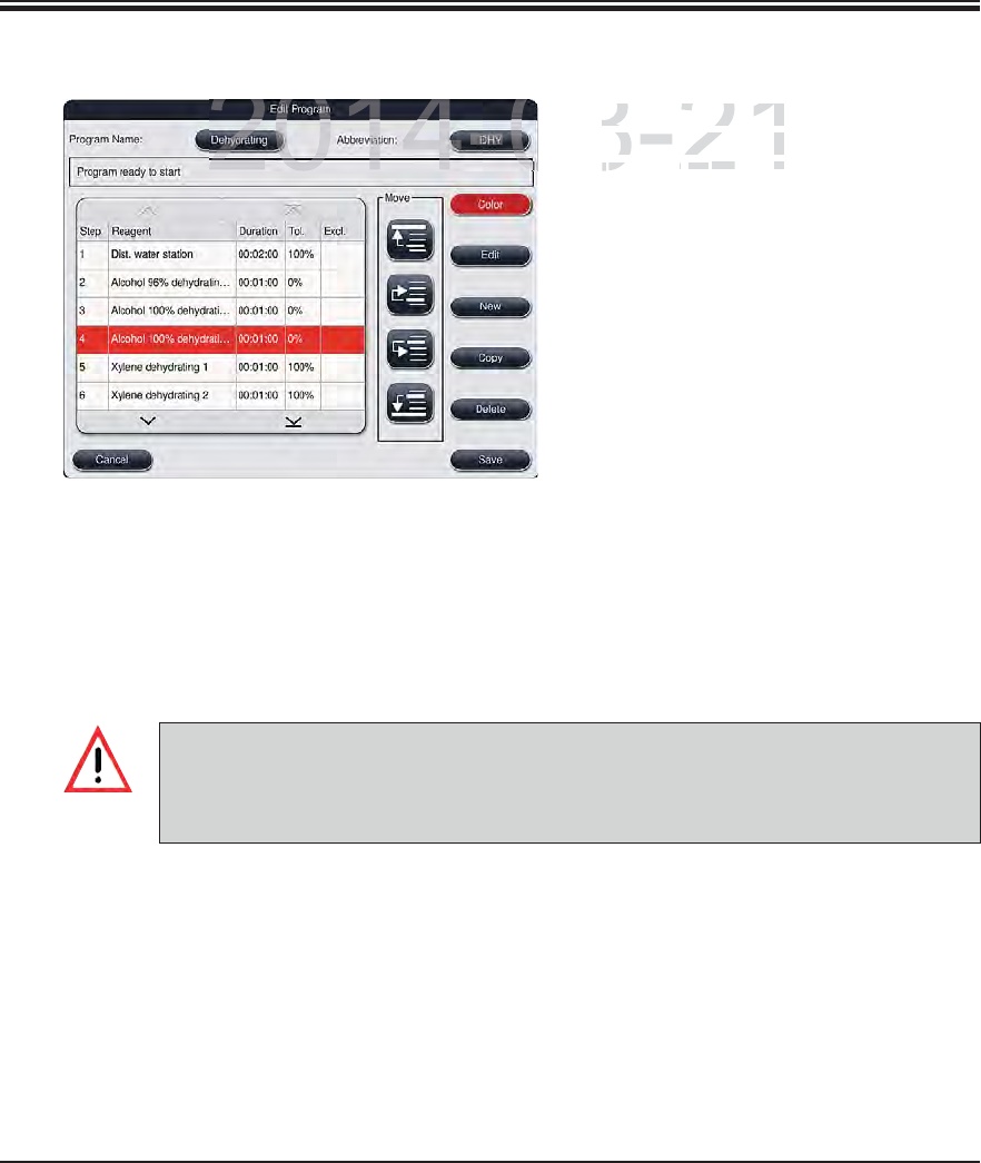
70 Instructions for Use V 0.5 RevC - 08/2014
5. Operation
5.9.7 Resorting a program step
The program step is highlighted in red
upon selection. Now the "Move" buttons
(1-4, Fig. 48) are active.
The "Save" button saves the current
status.
If an oven step is used as a first program step, a flammable solvent must not be present
in the load station of the input drawer under any circumstances.
This can cause a detonation in the oven, which can cause the operator to be burned,
specimen loss and damages to the instrument and equipment.
Fig. 48
1Press to move the selected program
step to the first row.
2Press to move the selected program
step one row up.
3Press to move the selected program
step one row down.
4Press to move the selected program
step to the last row.
1
2
3
4
DRAFT
DRAFT
DRAFT
2014-08-21
Th
e program step
The program step
upon selection. No
wpon selection. Now
((
141
Fig
4848
) are ac) are ac
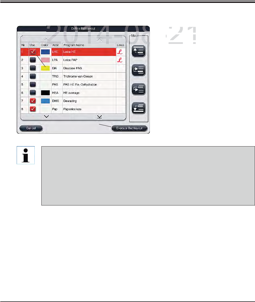
71
Leica HistoCore SPECTRA ST
5. Operation
5.9.8 Prioritizing programs
Fig. 49
After all desired staining programs
have been entered, the bathlayout
has to be generated. To do so, pro-
ceed as follows:
In the first step, the supervisor
should define which programs are
to be taken into the bathlayout. The
programs are activated via the radio
button (see 1, Fig. 49).
The position of the program deter-
mines its priority for the integration
into the bathlayout
1
Priority:
Leica staining programs are always placed at the beginning of the program list. The
positions of the Leica staining programs cannot be changed.
The positions of the user-defined programs can be moved.
The user-defined programs with low position numbers are easier to take into account
when creating the bathlayout than programs with high position numbers.
We recommend positioning user-defined programs with high specimen throughput at
the beginning of the program list, following the Leica staining programs.
If a higher priority is to be assigned to a staining program, it must be moved higher in the list
using the "Move" button:
The program is moved to the first row (2, Fig. 49)
The program is moved one row up (3, Fig. 49)
The program is moved one row down (4, Fig. 49)
The program is moved to the last row (5, Fig. 49)
Due to the new prioritization, the bathlayout has to be newly created (see Chap. 5.9.9).
2
3
4
5
6
DRAFT
DRAFT
DRAFT
2014-08-21
A
f
ter all de
sAfter all des
h
ave
b
een
ehave been e
has to be geas to be ge
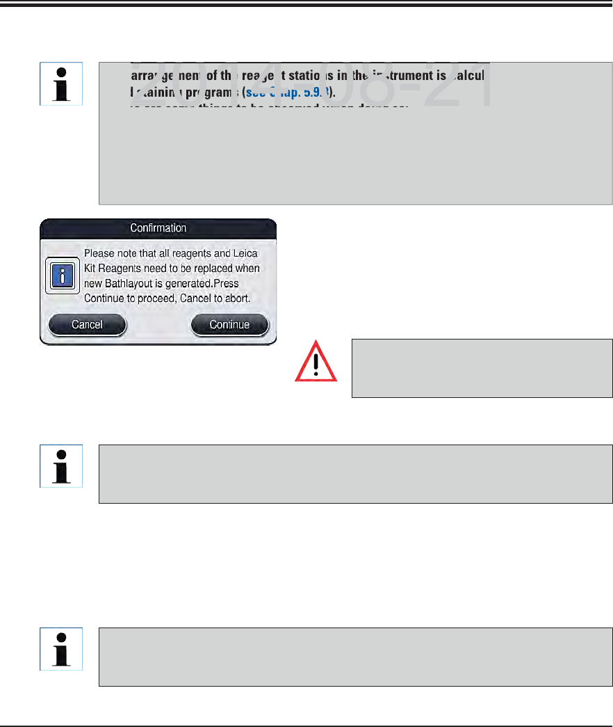
72 Instructions for Use V 0.5 RevC - 08/2014
5. Operation
Integration of Leica staining programs
If the software detects that a Leica staining program is integrated into the bathlayout, an
information message (Fig. 51) opens, prompting the user to scan the Leica reagent kit in
the next step.
When prompted by an information message (Fig. 52) on the screen, stop the carton's pack-
aging label in front of the RFID sensor on the front of the instrument (1, Fig. 53) to scan it.
Likewise, scan the labels of the individual reagent bottles when prompted.
5.9.9 Creating a bathlayout
The arrangement of the reagent stations in the instrument is calculated using the priori-
tized staining programs (see Chap. 5.9.8).
These are some things to be observed when doing so:
Leica staining programs are taken into account first,
Staining and differentiation solutions are placed as close as possible to the water
flow cuvettes,
The program prioritization and process class assignment are observed,
Sequential process steps must be located close to each other.
To start calculating the bathlayout, press the
"Define bathlayout" button (6, Fig. 49).
Press the "Create bathlayout" button to proceed
or the "Cancel" button to return to the program
selection.
Fig. 50 Be sure to observe the warning mes-
sage displayed after pressing the "Define
bathlayout" button (Fig. 50)!
Procedure for scanning the Leica reagent kit
The user has 3 minutes to scan the reagents for the carton's packaging label and
1 minute per reagent bottle.
If the time is not used, the user is prompted to restart or resume the scanning process.
DRAFT
DRAFT
DRAFT
angement of the reagent stations in the instrument is calcula
d staining programs
ee Chap.
5.9.8
)
2014 08 21
se are some things to be observed when doing
2014 08 21
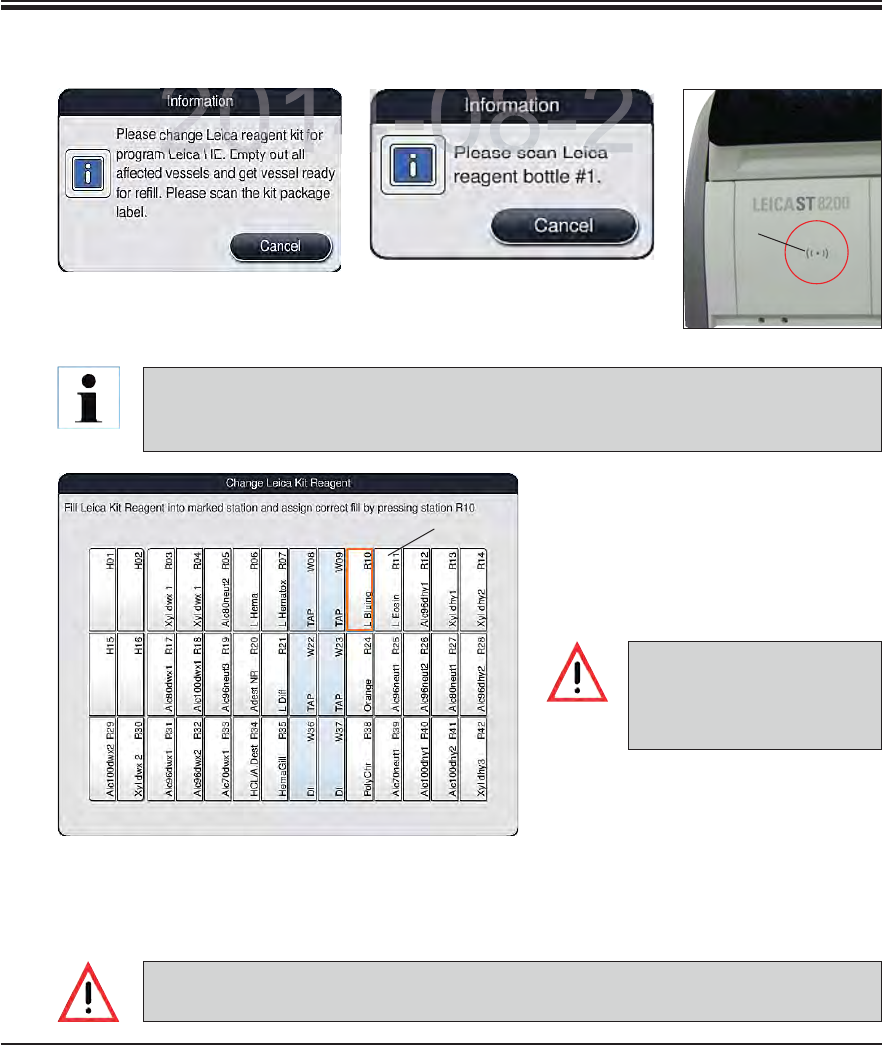
73
Leica HistoCore SPECTRA ST
5. Operation
1
1
Fig. 53
Fig. 54
Fig. 51
Fig. 52
Reagent cuvettes must al-
ways be filled outside of the
instrument in compliance
with the safety information.
5.9.9 Creating a bathlayout (continued)
The reagent management system (RMS) automatically takes over the following data for
the Leica reagents: The use-by date (onboard shelf life), remaining number of slides,
max. number of slides, expiration date and the batch number.
After scanning each individual re-
agent bottle, the instrument prompts
the user to fill this into a reagent
cuvette and to place it into the in-
strument at the specified position
(1, Fig. 54).
Confirm the correct insertion by
touching the specified position on
the screen.
Repeat these steps for all reagents
of the Leica reagent kit.
The arrangement of the bathlayout is to be followed exactly. Any deviation can lead to
undesired staining results.
DRAFT
DRAFT
DRAFT
2014-08-21
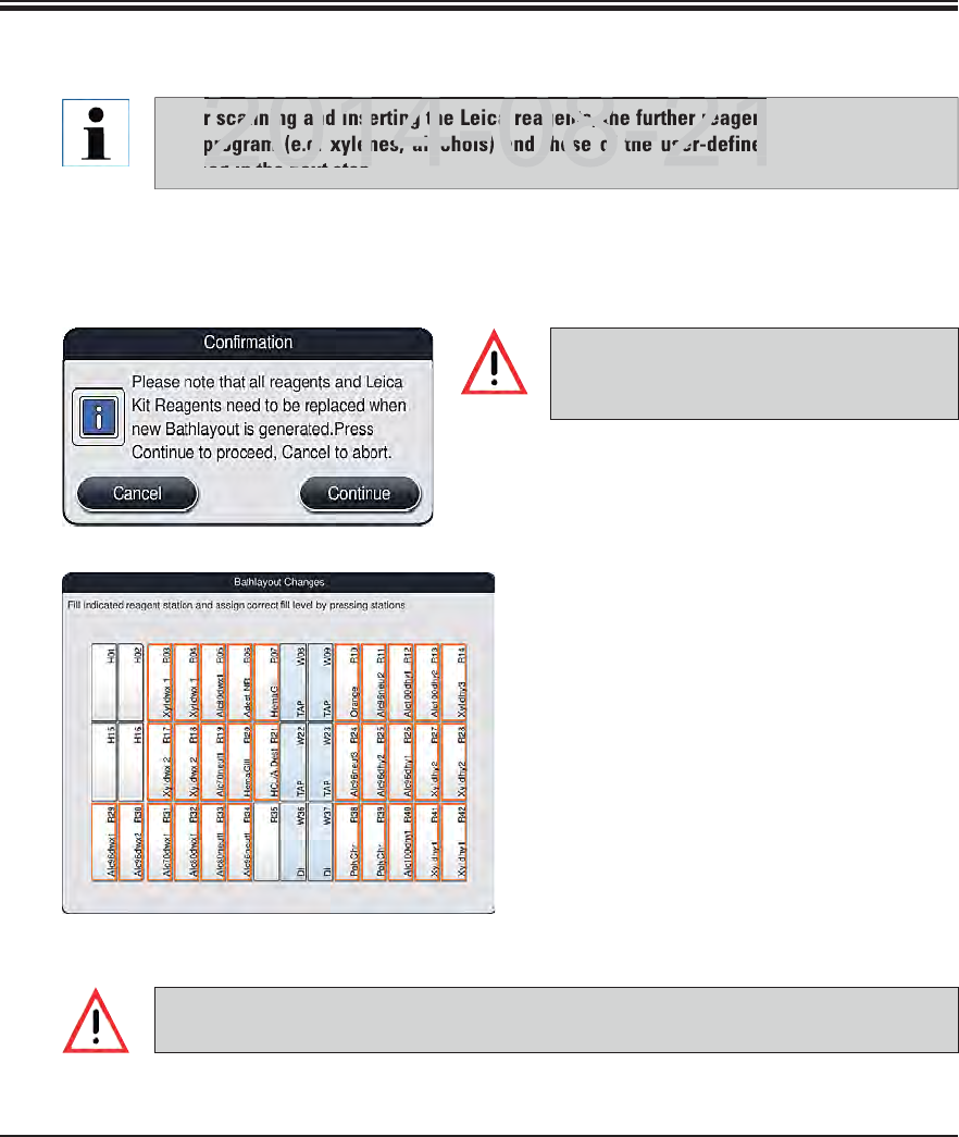
74 Instructions for Use V 0.5 RevC - 08/2014
5. Operation
Integration of user-defined programs
5.9.9 Creating a bathlayout (continued)
Fig. 56
To create the bathlayout, press the "Create bathlayout" button (6, Fig. 49).
Fig. 55
Be sure to observe the warning mes-
sage displayed after pressing the "Create
bathlayout" button (Fig. 55)!
Press the "Continue" button to proceed
or the "Cancel" button to return to the
program selection.
An overview of the bathlayout (Fig. 56)
is displayed.
The reagent stations to be filled are
outlined in orange (Fig. 56).
One by one, take the reagent cuvettes
out of the instrument, fill them with the
respective reagent outside of the instru-
ment and return them to the correct
position.
Touch the corresponding station on the
screen to confirm the respective reagent
change or refilling.
Repeat these steps for all displayed,
marked stations.
The arrangement of the assignment plan is to be followed exactly. Any deviation can
lead to undesired staining results.
After scanning and inserting the Leica reagents, the further reagents of the Leica stain-
ing program (e.g. xylenes, alcohols) and those of the user-defined programs are pro-
cessed in the next step.
DRAFT
DRAFT
DRAFT
2014 08 21
canning and inserting the Leica reagents, the further reagent
program (e.g. xylenes, alcohols) and those of the user-defined
sed in the next step
2014 08 21
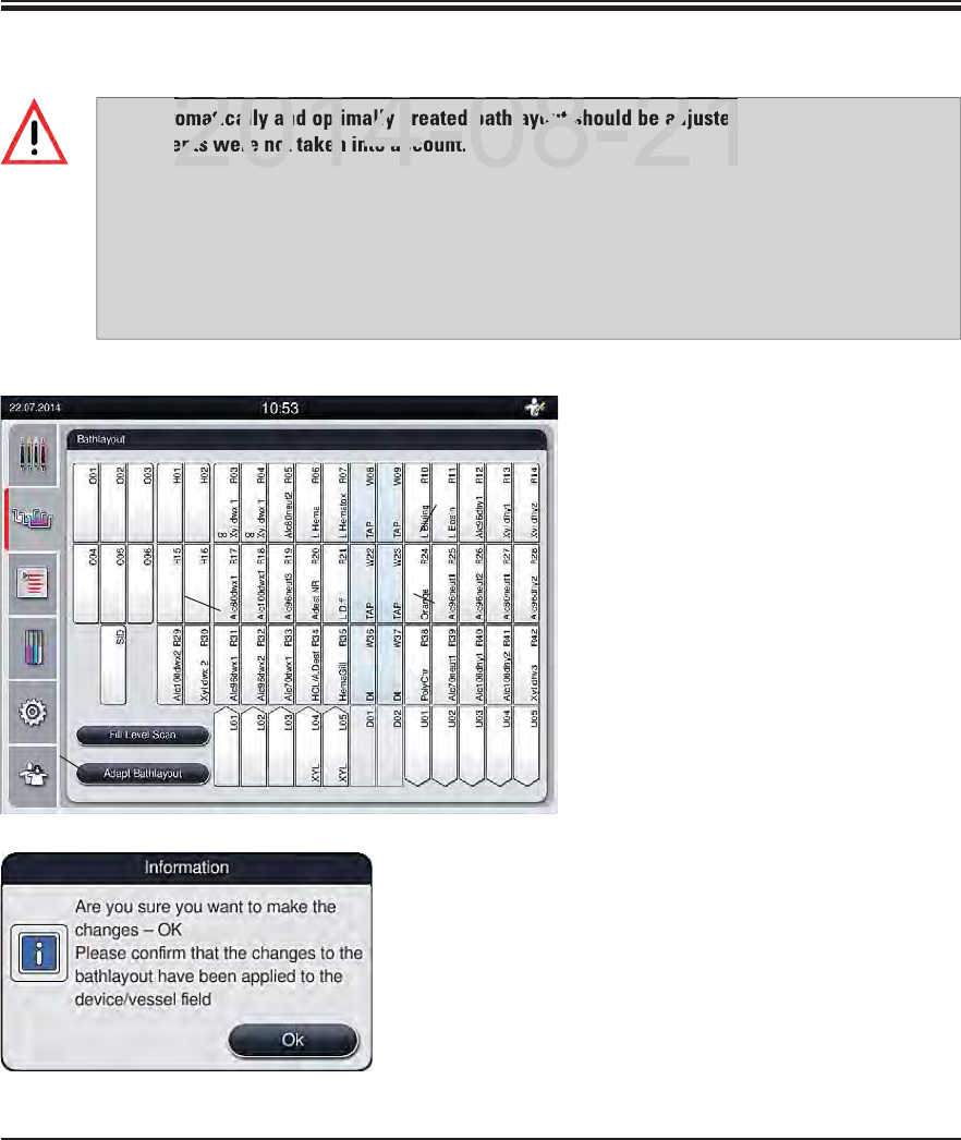
75
Leica HistoCore SPECTRA ST
5. Operation
5.9.10 Adjusting a bathlayout
If you need to adjust the bed layout
created by SPECTRA ST, which takes
into account all optimized regula-
tions, this can be done by means of
the function "Adapt Bathlayout".
Using this function, station place-
ments can be moved to their posi-
tions within the bathlayout and/or
duplicated.
To do so, proceed as follows:
In the station assignment view,
press the "Adapt Bathlayout" (1,
Fig. 57) button.
Observe the messages that follow
(Fig. 58+Fig. 59) and confirm or
press "Cancel" (Fig. 59) to return to
the station assignment view.
Fig. 58
Fig. 57
2
3
The automatically and optimally created bathlayout should be adjusted only if special user re-
quirements were not taken into account.
Each adjustment of the bathlayout can have a negative effect on the specimen throughput and
staining result!
The following rules must be observed when adjusting the bathlayout:
Reagent stations must not be moved from one side of the cuvette field to the other because
this causes unnecessarily long transfer times.
Duplicate stations should be inserted adjacent to the original station in the bathlayout.
4
1
DRAFT
DRAFT
DRAFT
2014 08 21
atically and optimally created bathlayout should be adjusted
ents were not taken into account
2014 08 21
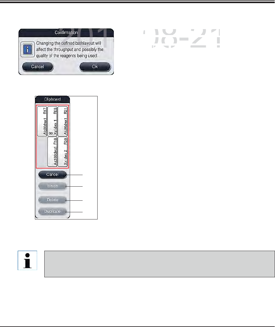
76 Instructions for Use V 0.5 RevC - 08/2014
5. Operation
The clipboard can be closed only if no more reagent stations are in it.
After changes have been made using the "Adapt Bathlayout" function, an automatic
fill level scan is performed!
Fig. 60
2
3
4
5
1
After confirmation, the "Clipboard" (Fig. 60)
will open, to which up to 6 reagent stations
(1, Fig. 60) can be moved.
There are two options for changing the bathlay-
out:
Move the reagent stations to connect them:
To move reagent stations, select them in-
dividually in the bathlayout by touching the
screen and then tapping an available position
in the clipboard.
This moves the reagent station to the clip-
board.
Finally, select the reagent station in the
clipboard by tapping and dragging it to the
desired (available) station (e.g. 2, Fig. 57) in
the bathlayout.
To save your changes, press the "Finish"
button and confirm the subsequent message
with a "Yes" or "No" to return to the clipboard.
To delete the changes, press "Cancel" and
answer the subsequent message with a "Yes".
Duplicate a reagent station
To duplicate a reagent station, select it in the
bathlayout by touching the screen.
Finally, press the "Duplicate" (5, Fig. 60) button.
5.9.9 Adapt Bathlayout (continued)
Fig. 59
DRAFT
DRAFT
DRAFT
2014-08-21
After confirmation, the
After confirmation, the
""
w
ill
open, to w
hi
c
h
up t
owill open, to which up to
((
11
Figig
6060
) can be movedbe moved
77
Leica HistoCore SPECTRA ST
5. Operation
Then, the reagent station will appear in the clipboard with an equivalence symbol () (4,
Fig. 57).
After this, select the duplicate reagent station in the clipboard by touching the screen and
place it in the desired (available) station, near the original station in the bathlayout.
To save your changes, press the "Finish" button and confirm the subsequent message with
a "Yes" or "No" to return to the clipboard.
To delete the changes, press "Cancel" and answer the subsequent message with a "Yes".
Duplicated reagent stations make sense for program steps with a long dwell time in a reagent.
Duplicated stations make two equivalent reagent stations available for a program step, which
ensures getting a high specimen throughput.
Leica reagent stations, marked by an "L" before the reagent name (3, Fig. 57), cannot be
duplicated
Duplicated reagent stations can be deleted using the "Delete" button (4, Fig. 60). To do
so, mark them in the bathlayout by touching them and pressing the "Delete" button.
5.9.9 Adapt Bathlayout (continued)
DRAFT
DRAFT
DRAFT
2014 08 21
ca reagent stations, marked by an "L" before the reagent nam
duplicated
2014 08 21
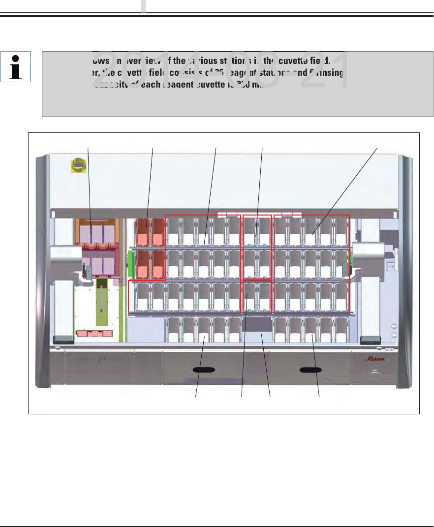
78 Instructions for Use V 0.5 RevC - 08/2014
3
976
54
21
8
6. Daily Instrument Setup
6.1 Preparing the instrument for daily setup
Fig. 61
16 oven stations 65 unloading stations,
24 heated reagent stations (optional) 7Dry transfer station
3Left reagent cuvette field 8Rinsing water stations (group of two)
4Rinsing water stations (group of four) 95 loading stations
5Right reagent cuvette field
Fig. 61 shows an overview of the various stations in the cuvette field.
Altogether, the cuvette field consists of 36 reagent stations and 6 rinsing water stations.
The max. capacity of each reagent cuvette is 380 ml.
When using the optional module with four reagent cuvettes that can be individually heated,
32 reagent stations are available.
DRAFT
DRAFT
DRAFT
p
p
p
ows an overview of the various stations in the cuvette field
r, the cuvette field consists of 36 reagent stations and 6 rinsing w
capacity of each reagent cuvette is 380
ml.
2014 08 21
2014 08 21
79
Leica HistoCore SPECTRA ST
6. Daily Instrument Setup
The reagent cuvettes are always to be filled or drained outside of the instrument to
avoid or reduce the risk of spilling reagents into other reagent cuvettes and onto inte-
rior instrument components. Proceed carefully and thoroughly when filling or draining
the reagent cuvettes and follow the respectively applicable laboratory specifications.
If reagents were spilled or another reagent station has been contaminated, it must be
cleaned and re-filled.
6.2.1 Preparation and handling of reagent cuvettes
To ensure that everything runs smoothly in the instrument, observe the following notes and
proceed as follows.
Attaching the reagent cuvette clip
Check whether the reagent cuvette clip is correctly attached to the reagent cuvette. If this is
not the case, fasten the clip according to Fig. 62.
Filling and draining reagent cuvettes
6.2. Daily setup of the instrument
Open the instrument cover and remove the covers from the reagent cuvettes.
Switch on the instrument.
Automatic fill level scan when initializing the instrument
During the initialization, fill level scans are automatically carried out in the following areas:
Reagent cuvettes
Water flow cuvettes
Reagent cuvettes of the loading and unloading stations
Oven station
Heated reagent cuvettes (optional)
Before setting up the instrument every day, check the water inlet to the instrument and
turn it if necessary.
If there are still racks, reagent cuvettes that are insufficiently filled or still covered, and/
or water flow cuvettes that are not ready to use in the instrument, this is determined
during the automatic fill level scan and displayed when finished.
DRAFT
DRAFT
DRAFT
6
2014-08-21
ore setting up the instrument every day, check the water inle
urn it if necessary.
2014-08-21
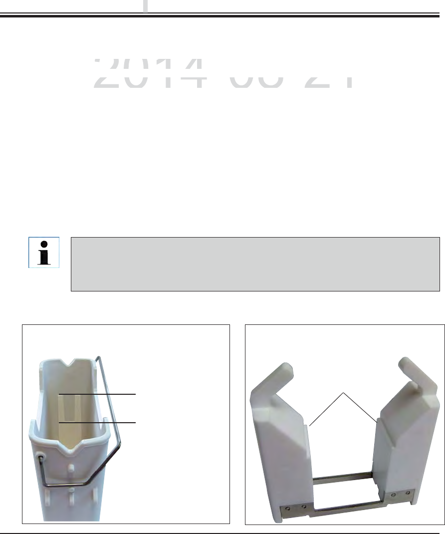
80 Instructions for Use V 0.5 RevC - 08/2014
6. Daily Instrument Setup
Maximum fill level
Minimal fill level
Carefully insert the reagent cuvette with clip into the cuvette field so that the clip is on
the right side of the reagent cuvette when looking at the cuvette field.
This orientation of the clip is recommended also for placing the reagent cuvettes in the
loading or unloading station and in heated reagent cuvettes (see Optional Accessories).
Correct fill level of the reagent cuvettes
To fill the reagent cuvettes, observe the fill level marks inside the reagent cuvettes (see
marks in Fig. 62 and Fig. 63).
A sufficient filling level is ensured if the level of the reagents is between the maximum and
minimum fill level marks (see marks in Fig. 62).
If the insert for special dyes (Fig. 63) is to be used in the reagent cuvettes (also heated), first
put it into the reagent cuvette and then fill the reagent at least up to the displayed minimum
filling level (see mark in Fig. 63).
Inserting the reagent cuvette into the bathlayout
Select "Bathlayout" in the main menu (see Chap. 5.5) and insert the reagent cuvette into the
correct position according to the arrangement of the bathlayout.
6.2.1 Preparation and handling of reagent cuvettes (continued)
Fig. 62
Correct fill level of the reagent cuvettes
Minimal fill level
Fig. 63
Correct fill level when using the insert for
special dyes
DRAFT
DRAFT
DRAFT
p
p
p
2014-08-21
e
l of the reagent cuvettes
el of the reagent cuvettes
e
agent cuvettes, observe the fill level marks inside the re
aeagent cuvettes, observe the fill level marks inside the rea
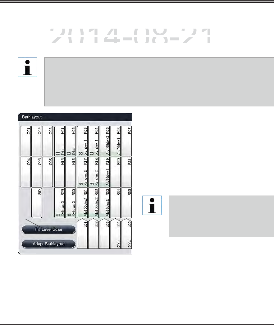
81
Leica HistoCore SPECTRA ST
6. Daily Instrument Setup
6.2.2 Automatic fill level scan
After filling and inserting the reagent cuvettes, the automatic fill level scan (1, Fig. 64) should be
carried out for verifying that all reagents used have the correct fill level.
1
Irregularities during the fill level scan
are displayed on the screen. Follow
the information messages and, for ex-
ample, correct the fill level, remove
the cover, add reagent cuvettes, etc.
To start the fill level scan, proceed as follows:
Call up "Bathlayout" in the main menu (see
Chap. 5.5).
The "Fill Level Scan" button (1, Fig. 64) is in the
lower part of the menu screen.
Press this button to start the fill level scan.
Fig. 64
The load and unload stations are not taken into account when creating the bathlay-
out. Reagents in the load and unload stations have to be defined and monitored by the
user.
The reagents in the loading and unloading stations are not monitored by the reagent
management system. Therefore the user is responsible for making sure the reagents
in these stations are in flawless condition.
DRAFT
DRAFT
DRAFT
6
2014-08-21
a
nd inserting the reagent cuvettes, the automatic fill level s
cand inserting the reagent cuvettes, the automatic fill level sc
f
or veri
f
ying that all reagents used have the correct
f
ill leve
for verifying that all reagents used have the correct fill leve
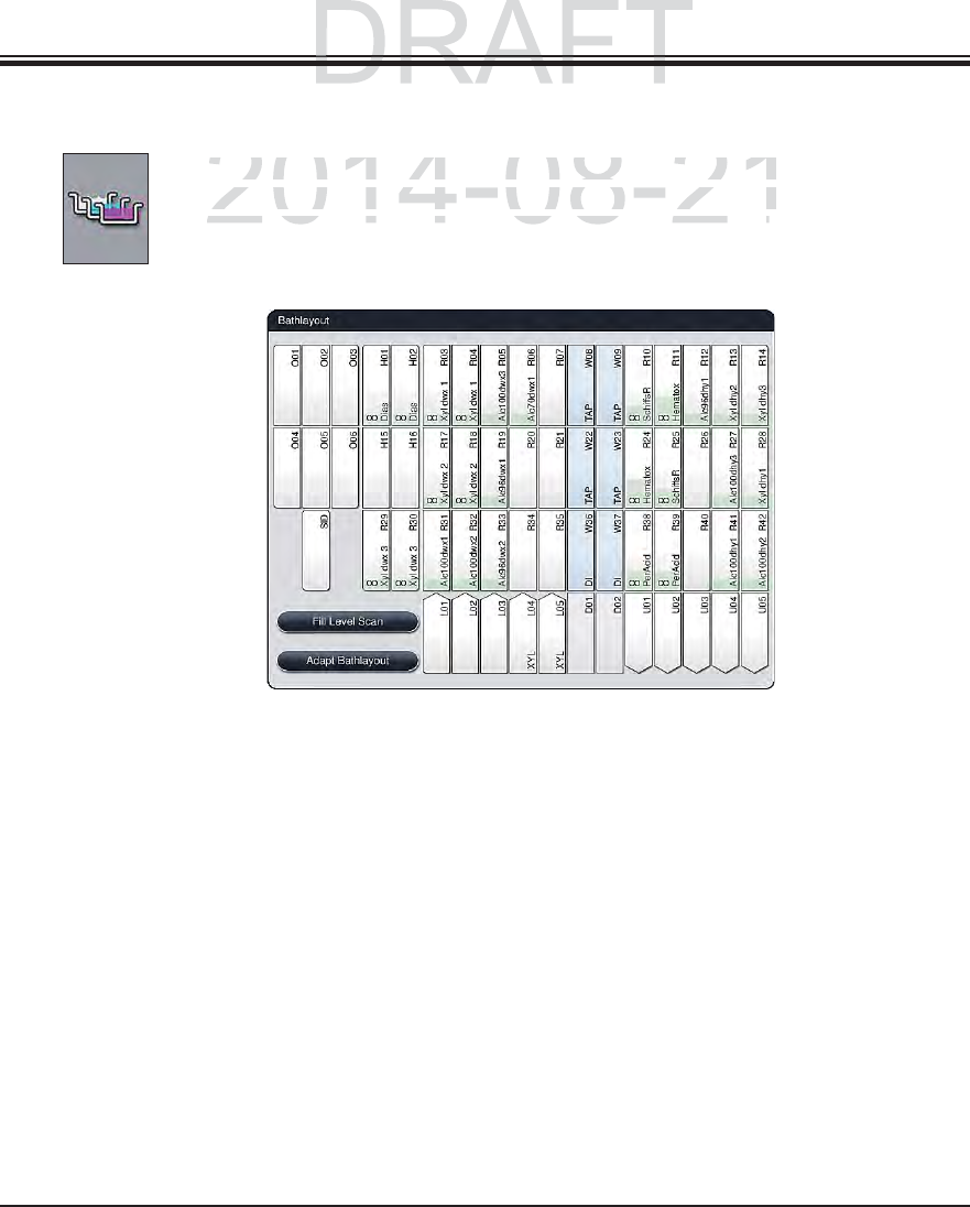
82 Instructions for Use V 0.5 RevC - 08/2014
6. Daily Instrument Setup
6.3 Reagent management system (RMS)
The bathlayout in the instrument is illustrated by pressing the adjacent menu button.
This display shows the current layout of the reagent stations, the rinsing water sta-
tions and the loading and unloading stations in the instrument.
The bathlayout is empty when the instrument is delivered, because reagents still have not been
defined and a bathlayout has not yet been created.
If reagents and programs were defined (see Chap. 5.8.1) and the bathlayout was created, the
overview shows all stations in the instrument in their real order.
Each reagent cuvette shown in the bathlayout contains additional information:
Station number
Reagent name
A background color
Equivalence symbol for a duplicated reagent station
Fig. 65
DRAFT
DRAFT
p
p
p
2014-08-21
bathlayout in the instrument is illustrated by pressing the a
dbathlayout in the instrument is illustrated by pressing the ad
s
display shows the current layout of the reagent stations, t
hdisplay shows the current layout of the reagent stations, th
s and the loading and unloading stations in the instruments and the loading and unloading stations in the instrument
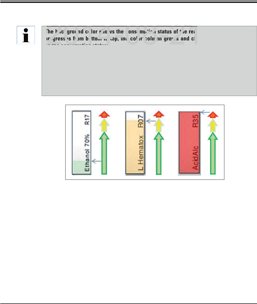
83
Leica HistoCore SPECTRA ST
6. Daily Instrument Setup
The background color shows the consumption status of the reagent (Fig. 66). When use
progresses from bottom to top, the color column grows and changes color, depending
on the consumption status:
Green: Consumption status between 0-80 % of the maximum use limit
Yellow: Consumption status between 80-95 % of the maximum use limit
Red: Consumption status between 95-100 % of the maximum use limit
As soon as the "Red" consumption status has been reached, but no later than when the
station flashes red, the reagent in question has to be replaced. If this is not done, Leica
staining programs are no longer able to start.
6.3 Reagent management system (RMS) (continued)
Fig. 66
DRAFT
DRAFT
DRAFT
6
2014 08 21
background color shows the consumption status of the reag
progresses from bottom to top, the color column grows and cha
on the consumption status:
2014 08 21
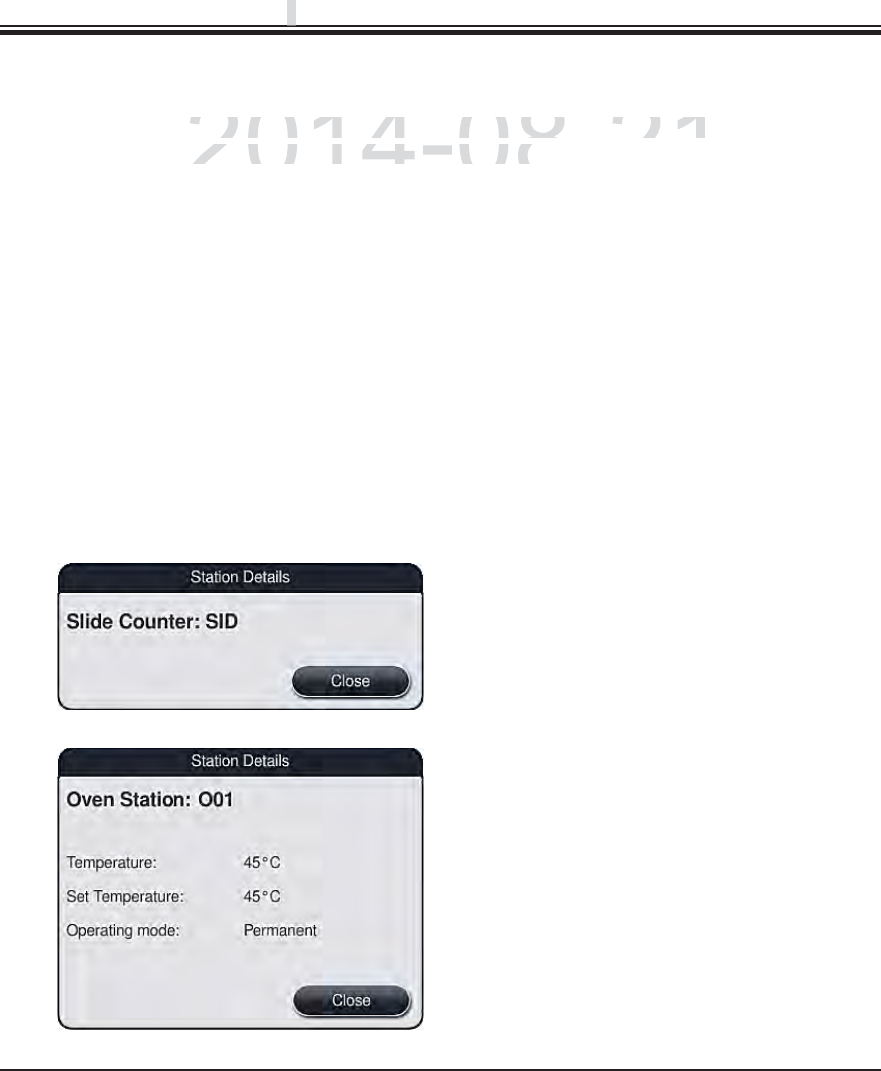
84 Instructions for Use V 0.5 RevC - 08/2014
6.4 Station features
Slide reader module (SID):
When this station is touched, a note appears
saying that this station is the slide reader mod-
ule. The "Close" button is used to close the dis-
play.
Oven stations:
The detail view of an oven station shows:
The current temperature,
The target temperature adjustment and
The operation mode of the 6 oven stations.
The "Close" button is used to close the display.
Touching a station in the bathlayout will display more information (station details). The follow-
ing station types are distinguished by their abbreviation:
Fig. 67
Fig. 68
6. Daily Instrument Setup
L01-L05 Load stations
SID Slide reading module and title block identification (optional)
O01-O06 Oven stations for drying the slides and starting to melt the paraffin
R01-R42 Reagent stations
W08-W09
W22-W23
Rinsing water stations (group of four)
W36-W37 Rinsing water stations (group of two)
H01-H02
H15-H16
Heated reagent stations (optional)
D01-D02 Dry transfer stations
U01-U05 Unloading stations in the output drawer
DRAFT
DRAFT
DRAFT
p
p
p
2014-08-21
t
ion in the bathlayout will display more information (station
tion in the bathlayout will display more information (station
e
s are distinguished by their abbreviation
:s are distinguished by their abbreviatio
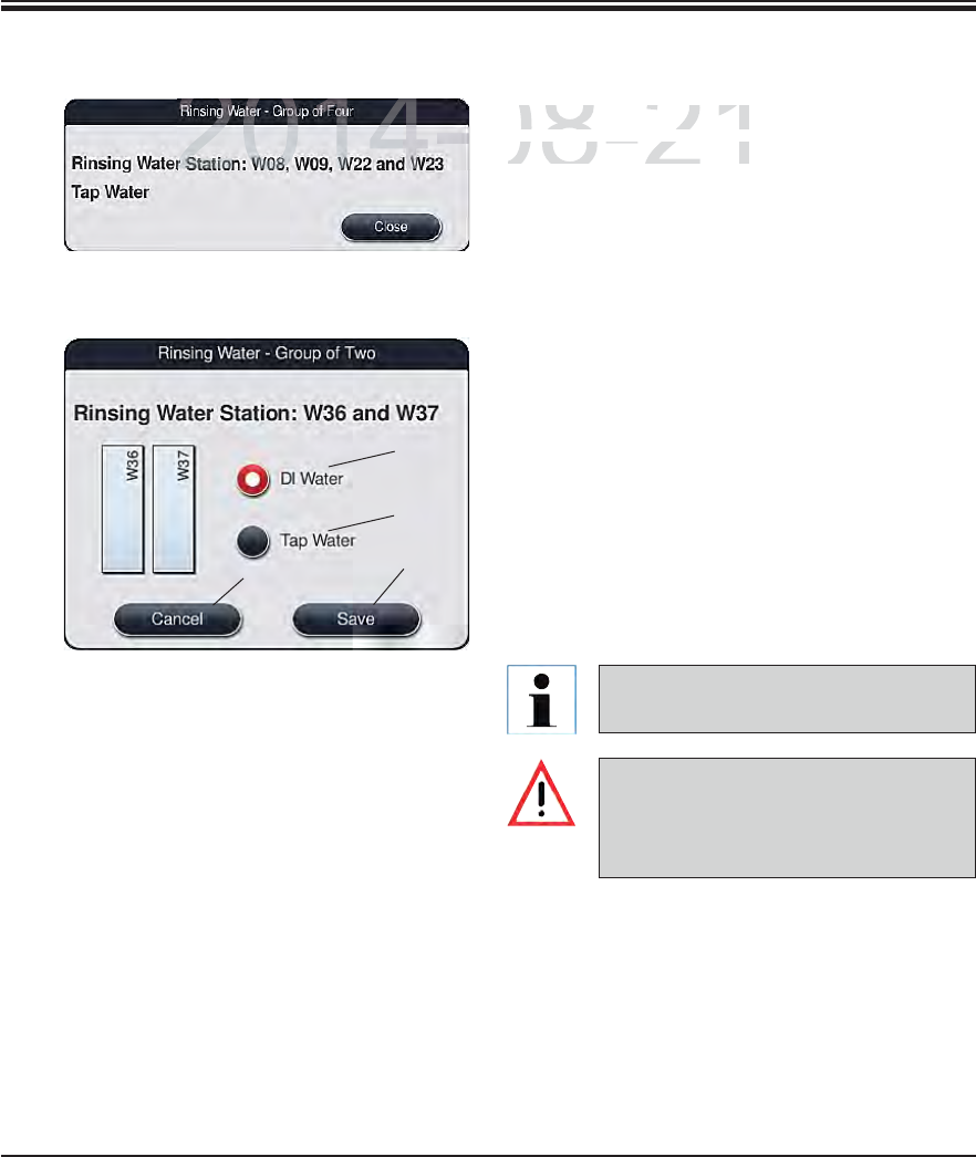
85
Leica HistoCore SPECTRA ST
Rinsing water stations (group of four):
The detail view of a rinsing water station shows
all other rinsing water stations that are connect-
ed to the same water circuit. The "Close" button
is used to close the display.
Fig. 69
6. Daily Instrument Setup
6.4 Station features (continued)
Rinsing water stations (group of two):
When you touch a group-of-two rinsing wa-
ter station, an information window opens that
shows the 2 water stations, which are connect-
ed to the second water circuit with, for example,
distilled water or demineralized water (1, Fig. 70)
or rinsing water (2, Fig. 70) .
Depending on the connected supply, the cor-
responding selection will have to be made in
this menu.
The correct assignment and connec-
tion of the water flow cuvettes is ab-
solutely necessary for achieving good
staining quality.
Fig. 70 To install an additional running water
connection, see Chap. 4.2.
To take over the setting, press the "Save" (3,
Fig. 70) or "Cancel" button (4, Fig. 70) to close
the display.
43
2
1
DRAFT
DRAFT
DRAFT
6
2014-08-21
Rinsing water stations
(gRinsing water stations (g
The detail view of a rinsi
nThe detail view of a rinsin
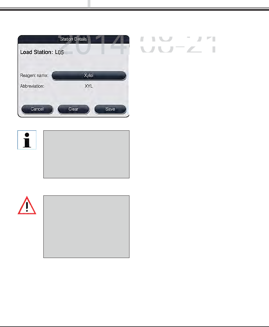
86 Instructions for Use V 0.5 RevC - 08/2014
6.4 Station features (continued)
The slide racks are transported
into any free unload station at
the end of a program. There-
fore, all unload stations must
be filled with the same reagent.
The samples can potentially
become damaged if this is not
observed.
Fig. 71
6. Daily Instrument Setup
The load and unload stations
are not taken into account
when creating the bathlayout.
Reagents in the load and un-
load stations have to be defined
and monitored by the user.
Load and unload stations in the drawers:
No reagents have been assigned yet to the load
and unload stations in the factory condition of
the instrument.
To assign a reagent, run the following steps:
Select the corresponding load or unload sta-
tion in the bathlayout (see Fig. 20) by touching
it.
In the newly opened "Station details" window,
press the black "Reagent name" button to
open the list of available reagents (see Fig. 36,
Chap. 5.8).
Select the desired reagent by touching it and
then hit "Apply".
To apply the settings, press the "Save" button
or press "Cancel" to close the display.
The assigned reagent name is displayed in the
bathlayout.
If a reagent is no longer required in the load
or unload station, the assignment to the re-
spective reagent can be removed using the
"Delete" and "Save" buttons in the "Station
details" window.
Reagent stations:
An information window opens when the reagent
station is touched. It displays additional relevant
data regarding the station type.
DRAFT
DRAFT
DRAFT
p
p
p
2014-08-21
Load
a
n
d
u
nl
oad
s
t
a
ti
o
n
s
in
Load and unload stations in
No reagents have been assi
No reagents have been assi
fdl
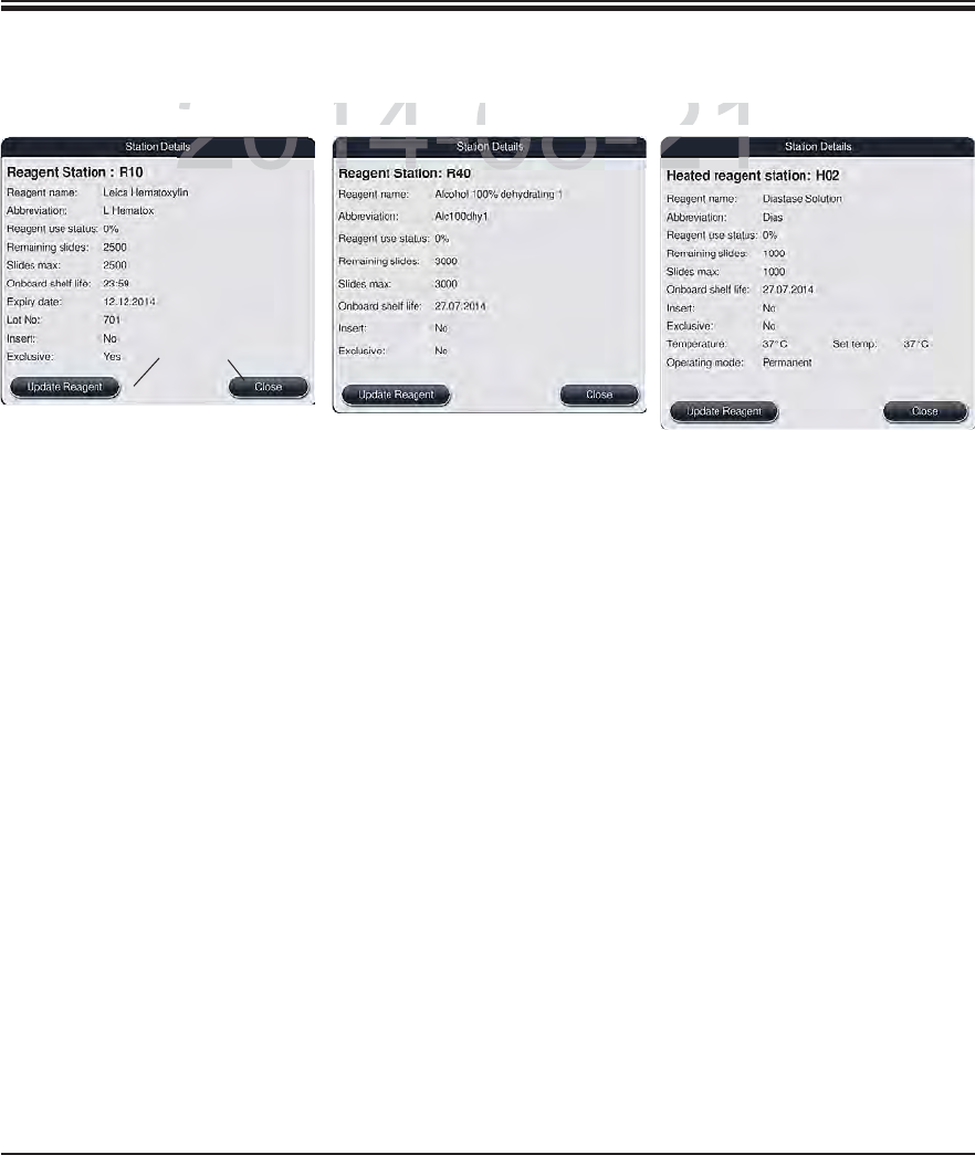
87
Leica HistoCore SPECTRA ST
6. Daily Instrument Setup
6.4 Station features (continued)
Fig. 72
Leica reagent station
Fig. 73
Reagent station
Fig. 74
Heated reagent station
Reagent name/abbrevia-
tion
See Chap. 5.8.1
Consumption status See Chap. 6.3
Remaining slides/max.
slides
Displays the number of remaining processable slides. When inserting a
slide rack into the instrument, the slides contained in it are counted by the
slide reading module and subtracted from the number of remaining slides.
Onboard shelf life Displays the shelf life of the reagent filled into the reagent cuvette (see
Chap. 5.8.1).
Expiry date/batch number is applied automatically when scanning the packaging of the Leica
reagent kit.
Insert yes/no "Yes" indicates that the insert for special dyes and the slide rack for 5
slides is used. This station cannot be used for programs with slide racks
for 30 slides (see Chap. 5.5).
Exclusive Yes/No The setting "Yes" defines that the reagent is only assigned to one pro-
gram. "No" allows use by multiple programs (see Chap. 5.9.6).
Target temperature Indicates the user-defined temperature for a heated reagent station.
Operation mode Indicates the user-defined setting for a heated reagent station (activated
continuously or only when starting the program).
2
1
DRAFT
DRAFT
DRAFT
6
2014-08-21
ti
on
io
R
eagent stat
i
o
nReagent station
H
eate
d
r
eeated re
88 Instructions for Use V 0.5 RevC - 08/2014
6.4 Station features (continued)
6. Daily Instrument Setup
Reagent replacement
If the RMS indicates that a reagent is almost or completely consumed, a reagent change must
occur. This changeover must be confirmed by pushing the "Update Reagent" (1, Fig. 72) button.
When replacing the Leica reagents, first press the "Update Reagent" button and follow the
instructions for scanning and filling on the screen.
The "Close" (2, Fig. 72) button is used to close the display.
Updating the reagent status without replacing the corresponding reagent will inevita-
bly affect the staining quality negatively.
NEVER press the "Update Reagent" button if the reagent has not been replaced.
Each Leica reagent kit can only be scanned once!
Already added Leica reagents expire before their use-by date if a bathlayout is newly
created.
If the newly created bathlayout is subject to a final verification by the user or is to be
adapted and the Leica reagents have not yet been scanned and added, the following
procedure is recommended:
After creating the bathlayout, cancel the prompt to scan the Leica reagent kits.
Do not carry out any fill level scan.
Make up the Leica reagent kit scan and a fill level scan later.
This is used to prevent the Leica reagent kit from expiring early.
DRAFT
DRAFT
DRAFT
p
p
p
2014-08-21
c
emen
tcement
ndi
cates t
h
at a reagent
i
s a
l
most or comp
l
ete
l
y consume
d
, a
rndicates that a reagent is almost or completely consumed, a r
htbfidbhithhtbfidbhit
"Udt RdR
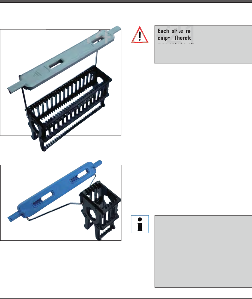
89
Leica HistoCore SPECTRA ST
6. Daily Instrument Setup
6.5 Prepare slide rack
Two different types of slide racks with compat-
ible clips are available for use in the SPECTRA
ST staining machine:
Slide rack for 30 specimen slides routine stain-
ings (Fig. 75).
Slide rack with layered clips for 5 slides for
special dyes (Fig. 76).
The colored clips must be correctly attached
prior to using the slide rack in the device.
The rack clips must be attached corresponding
to the previously defined program color (see
Chap. 5.9.1).
The specimen slide clips are available in 9 colors
(8 program colors & white) (see Chap. 9.2).
Fig. 76
Fig. 75
Special function of the white clip:
The white clip cannot be permanently
assigned to a staining program.
Corresponding to a "wildcard func-
tion", the white clip has to be reas-
signed to a program color each time
the program is started.
For this purpose, a selection menu
opens on the screen automatically af-
ter inserting the slide rack.
Each slide rack clip contains 2 RFID
chips. Therefore, the slide rack clips
may only be attached to the slide rack
after a potential microwave step for
specimen preparation.
DRAFT
DRAFT
DRAFT
6
2014-08-21
2014-
slide rac
chips. Therefor
lb tt
-21
08
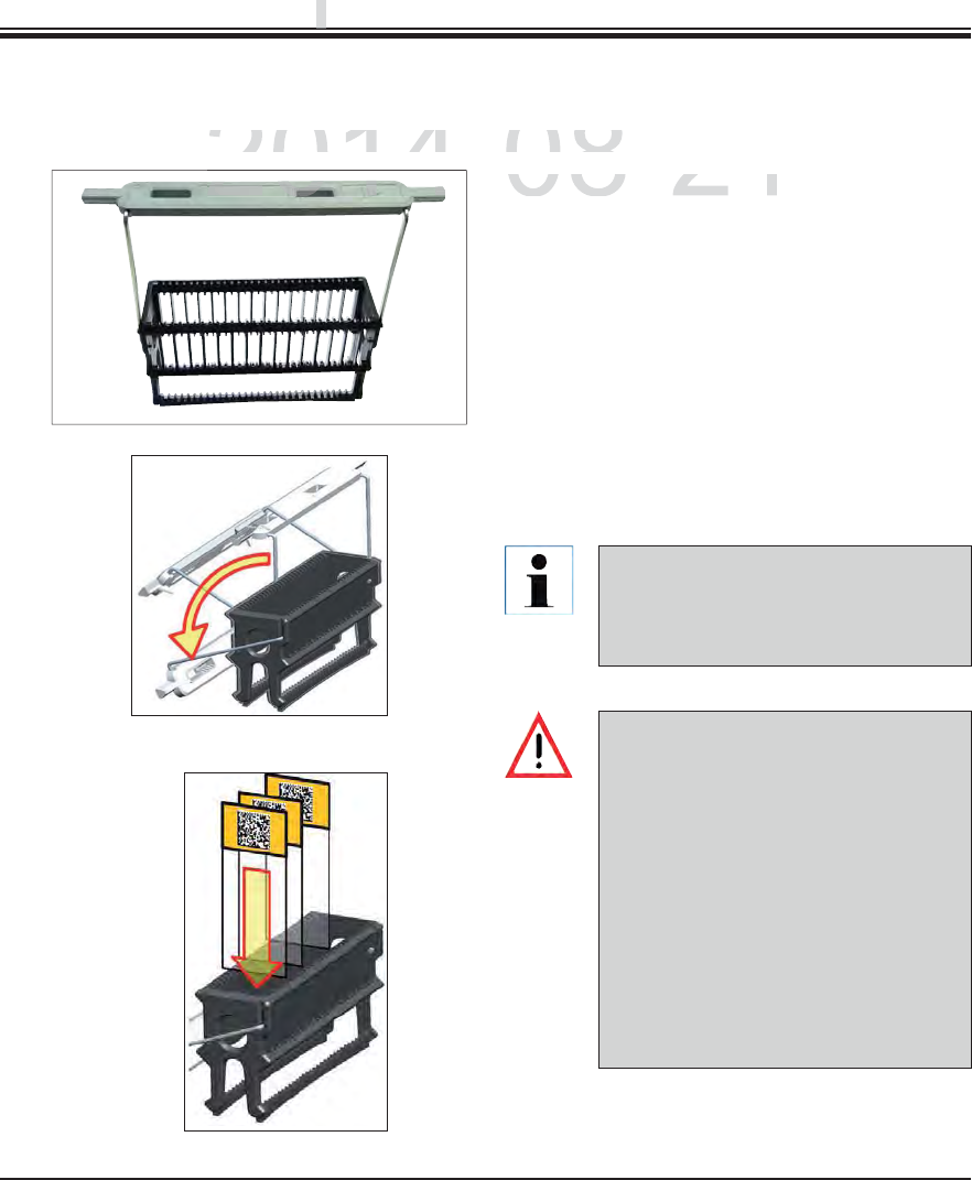
90 Instructions for Use V 0.5 RevC - 08/2014
Proceed as follows to attach or replace the slide rack clips:
6.5 Prepare slide rack (continued)
Detach the clip from the slide rack:
Slightly pull the clip apart so that the clip wire
can be pulled from the bore in the holder.
Attaching a clip to a slide rack:
Slightly pull apart the clip so that the clip wire
can snap into the respective bore in the holder.
Be sure that the clip is correctly positioned in
the upper position, centered above the slide
rack (Fig. 77).
Fig. 77
Fig. 78
Fig. 79
6. Daily Instrument Setup
Ø
Ø
For a stable placement for filling, fold
the clip to the side as far as it goes
(Fig. 78) so it can be used for addition-
al protection from tipping.
When inserting the slides, be abso-
lutely certain that the slide label is
pointing upwards and toward the user.
The side of the slide with the speci-
men must point toward the front side
of the slide rack.
The front side of the slide rack is la-
beled with the Leica logo. With the
clip attached, "Front" can be read
when looking at the clip (Fig. 79).
If the slides are not inserted correctly,
the samples can become damaged in
the further process sequence.
DRAFT
DRAFT
DRAFT
p
p
p
2014-08-21
ows to attach or replace the slide rack clips
:ows to attach or replace the slide rack clip
Detach the cli
p
from the sli
dDetach the clip from the slid
2014
2014-
91
Leica HistoCore SPECTRA ST
6. Daily Instrument Setup
6.5 Rack and preparatory work (continued)
6.6.1 Start the staining process
When using printable labels or manual labels on the slide rack clips and the slides,
they must be checked for solvent resistance in advance.
When inserting the slide into the slide rack, you have to make sure that the slides are
inserted into the respective slide rack for the desired staining program. The colored
slide rack clips allow secure assignment for the respective staining program.
Make sure that only one slide each is put into the insert and that the slides are not
jammed.
6.6 The staining process
The following requirements must be met to carry out the staining process:
All settings are optimized (parameters for oven, heated cuvettes, etc.).
The programs required for staining have been created (see Chap. 5.9.5).
The reagent stations are filled with the correct reagents (see Chap. 6.2.1).
A fill level scan has been carried out (see Chap. 6.2).
The slide racks intended for staining are filled and the correct clips are attached to the slide
racks (see Chap. 6.5).
The slide rack can be inserted using the input drawer only. Directly inserting it into any
reagent or oven station by opening the instrument cover is not permitted. These slide
racks cannot be recognized by the instrument and can cause collisions!
Fold the slide rack clip into the upright position (see Fig. 78).
If the input drawer is illuminated in green, press it and open the drawer.
As shown in Fig. 80, insert the slide rack into an available input drawer position.
Insert the slide rack so that both the Leica logo on the front side of the slide rack and the
"Front" label on the top of the colored clip are pointing toward the user. The arrow on the top
of the colored clip must point into the instrument.
Press the input drawer button again to close it again.
DRAFT
DRAFT
DRAFT
6
When using printable labels or manual labels on the slide ra
they must be checked for solvent resistance in advance.
2014 08 21
When inserting the slide into the slide rack, you have to make
2014 08 21
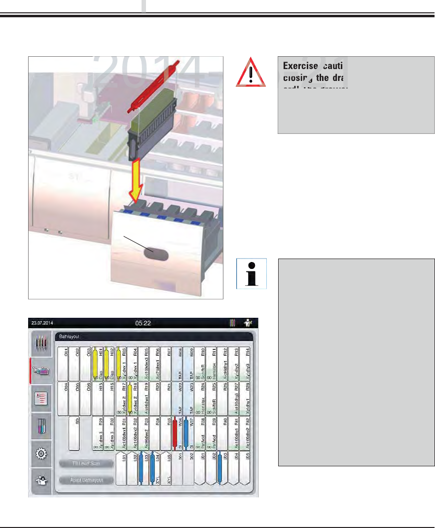
92 Instructions for Use V 0.5 RevC - 08/2014
Fig. 80
6. Daily Instrument Setup
1
An incorrectly oriented slide rack
is detected and displayed by the
instrument and must be corrected
by the user.
The system detects if a slide rack
has been inserted into the input
drawer with a slide rack handle
color, for which no program is
specified in the bathlayout and
the user is informed by a informa-
tion message. The slide rack must
be removed from the instrument.
Corresponding to the bootable
programs (see Fig. 82), attach the
correct colored clip to the slide
rack and re-insert it into the input
drawer.
Exercise caution when opening or
closing the drawers! Crushing haz-
ard! The drawers are motorized and
open automatically when the button
is pressed. Do not block the exten-
sion range of the drawers.
After closing the input drawer, the instru-
ment detects the RFID chip in the colored
clip.
The identified color of the clip and the as-
signed program abbreviation are displayed
in the bathlayout at the respective station
(Fig. 81).
6.7.1 Start the staining process (continued)
Fig. 81
DRAFT
DRAFT
DRAFT
p
p
p
2014-08-21
2014-
e cautio
closing the draw
Th d
8-21
08
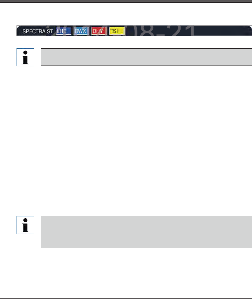
93
Leica HistoCore SPECTRA ST
6. Daily Instrument Setup
Fig. 82
For the inserted slide racks, the instrument calculates throughput-optimized start times
that can deviate from the order of the inserted slide rack.
Before the first program step, the instrument counts the slides used in the slide rack in the
slide reading module (see 2, Fig. 4).
The determined number of slides is recorded and processed in the RMS and the consumption
status of the respective reagents is updated.
Afterwards, the rack is transported into an oven station or reagent station, depending on
the defined first program step.
The slide racks are now integrated into the staining process.
6.7.1 Start the staining process (continued)
6.7.2 Monitoring the staining process
Using the following menu, the user can call up or monitor details for ongoing programs:
Bathlayout with station details (Fig. 81).
Process status display with calculated remaining program times and step times (see
Chap. 5.3).
The status bar (see Chap. 5.2) with date, time and symbols that refer to messages and
warnings that occurred.
The last 20 messages and warnings can be called up by touching the corresponding
symbol in the status bar (see 7+8, Fig. 17). This gives the user the opportunity to be-
come informed about past and current situations after the instrument is absent and initi-
ate the required actions, if necessary.
DRAFT
DRAFT
DRAFT
6
2014-08-21
2014-08-21
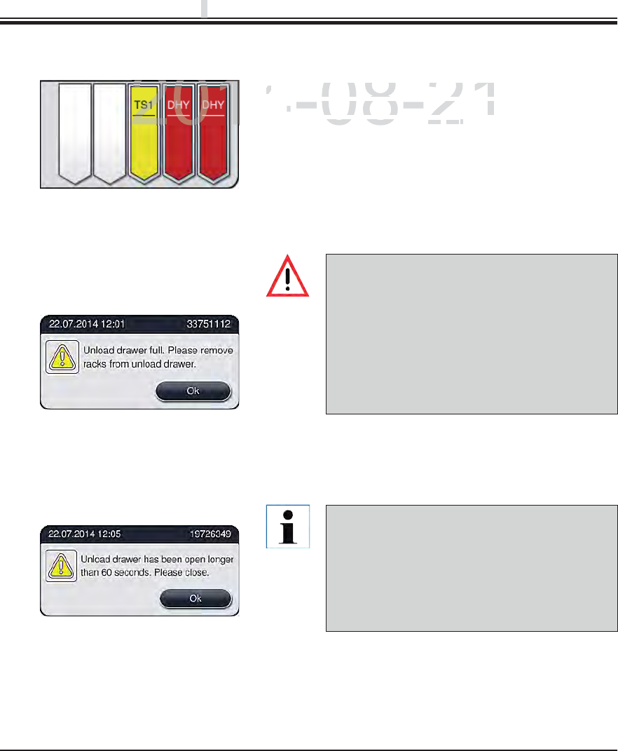
94 Instructions for Use V 0.5 RevC - 08/2014
6.7.3 Staining process completed
The output drawer must be opened and the slide
racks removed at the latest when the warning
message is received indicating that the output
station is completely occupied (Fig. 84). Failure
to comply with the warning message results in
not being able to transport further slide racks
into the output stations. Deviating step times
and delays in the staining process can change
the staining results.
Fig. 84
Fig. 83
Fig. 85
The user receives a message if the output drawer is
open for longer than 60 seconds (Fig. 85).
The warning message requests the user to close
the output drawer to prevent potential delays.
When the output drawer is open, the instrument
cannot place completely processed slide racks
into the unload stations. Deviating step times
and delays in the staining process can change
the staining results.
6. Daily Instrument Setup
Press the button on the output drawer for closing.
After a slide rack has run through the staining process,
it is transported into the output drawer and placed in
an available position (Fig. 83).
To remove the slide rack from the unload station, press
the button on the output drawer for opening and remove
the slide rack.
Press the button again after removal to close the output
drawer.
DRAFT
DRAFT
DRAFT
p
p
p
2014-08-21
After a slide rack has run through
ta slide rack has run through t
i
t
i
s transporte
d
i
nto t
h
e output
drit is transported into the output dr
an available position (ilable posit
Figig
8383
))
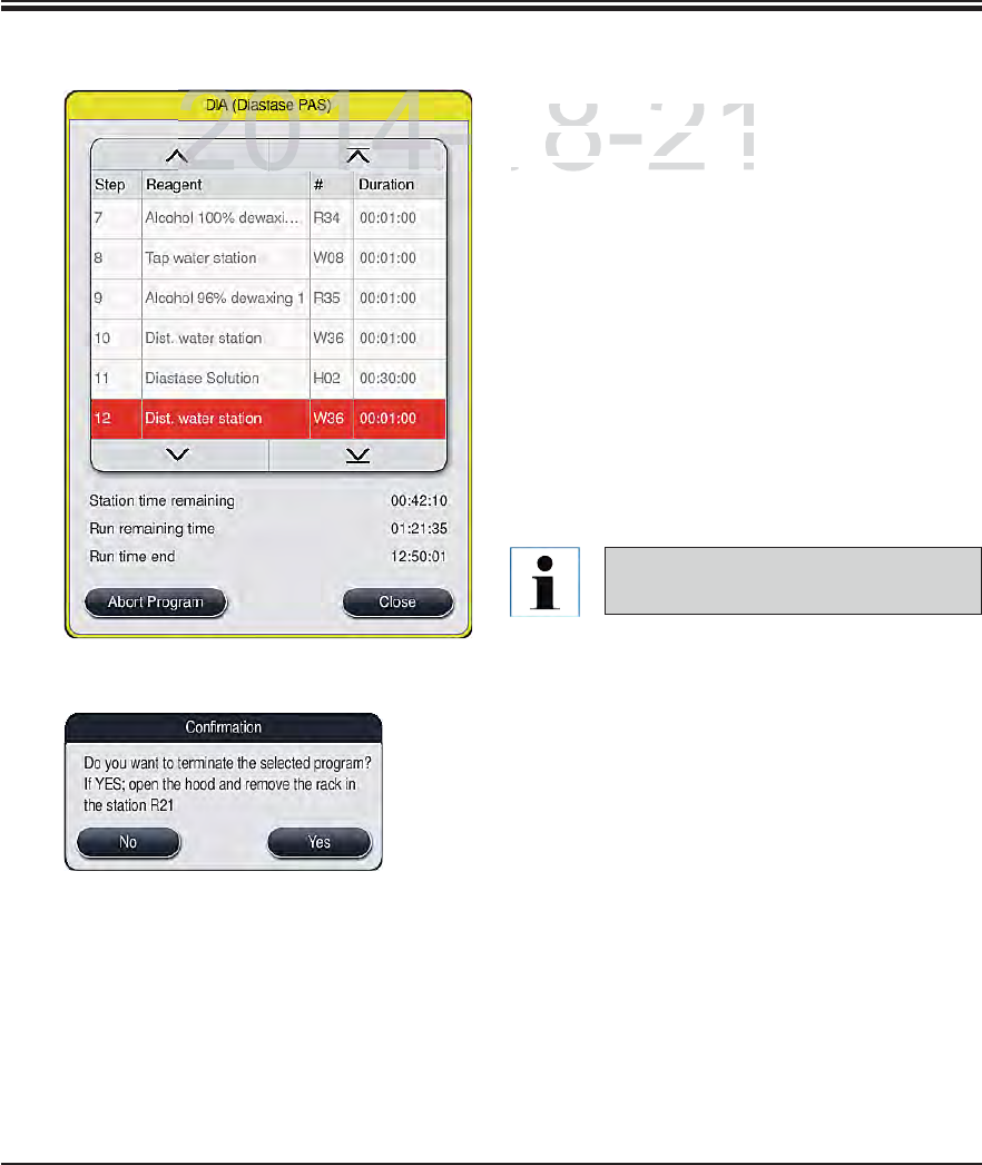
95
Leica HistoCore SPECTRA ST
6.7.4 Canceling the staining program
Staining programs can only be canceled via
the process status display.
To cancel a staining program, select the cor-
responding slide rack in the process status
display (see x, Fig. xx front) by touching it.
A list of program steps appears (Fig. 86), the
current step is marked in red.
The frame of the window displays the color
assigned to the program, the program name
and the stored abbreviation.
Press the "Cancel program" button.
In the following message, confirm the program
termination with the "Yes" button or return to
the process status display with "No".
Fig. 86
Fig. 87
The bathlayout is displayed after pressing the
"Yes" button. The position of the slide rack
is highlighted in orange in the instrument (1,
Fig. 88).
Open the instrument cover; remove the slide
rack from the highlighted station.
Close the hood again immediately.
Confirm the removal of the slide rack by press-
ing the marked station (1, Fig. 88).
The message notes (Fig. 87) are abso-
lutely necessary to observe.
6. Daily Instrument Setup
DRAFT
DRAFT
DRAFT
6
2014-08-21
S
taining programs ca
Staining programs ca
t
h
e process status
disthe process status dis
To cancel a staining pTo cancel a staining p
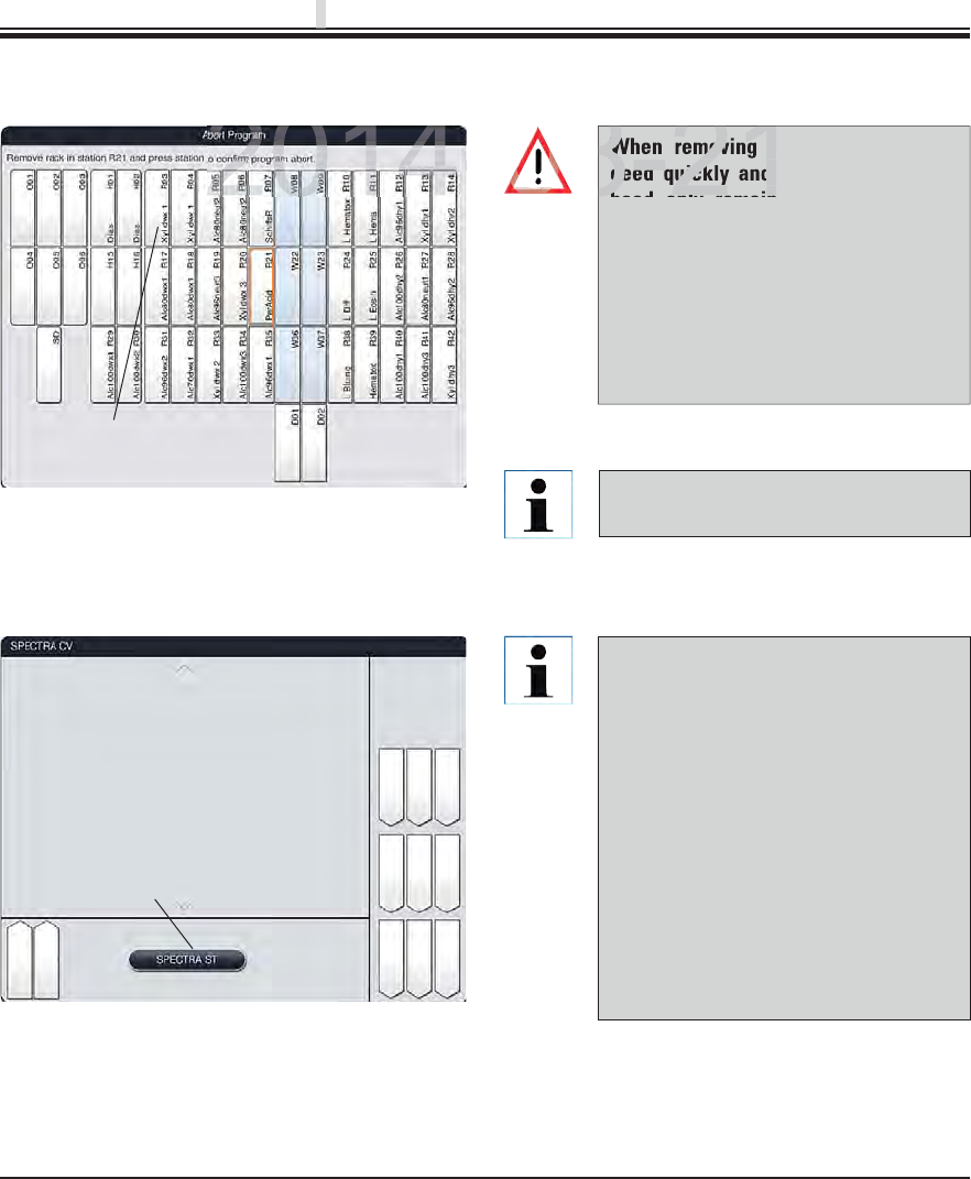
96 Instructions for Use V 0.5 RevC - 08/2014
6.7.5 Operation as a workstation
The SPECTRA ST can be operated as a
workstation together with the SPEC-
TRA CV robotic coverslipper. This al-
lows an uninterrupted workflow from
entering into the staining machine up
to removing the completely stained
and covered specimen slides. An op-
tional transfer station for the SPECTRA
CV is available for the SPECTRA ST
(see Optional Accessories). The op-
tional transfer station and connection
of a SPECTRA CV to the SPECTRA ST
may only be installed by a Leica-certi-
fied service technician.
Fig. 89
1
6. Daily Instrument Setup
Remaining staining programs are con-
tinued after a program termination.
Fig. 88
1
6.7.4 Canceling the staining program (continued)
When removing the slide rack, pro-
ceed quickly and make sure that the
hood only remains open for a short
amount of time. After opening the
hood, for safety reasons, all move-
ments are interrupted until the hood is
closed again. Deviating step times, de-
lays and changed staining results can
be caused each time the hood opens in
the staining process.
DRAFT
DRAFT
DRAFT
p
p
p
2014-08-21
When removing th
ceed quickly and
hd l i
8-21
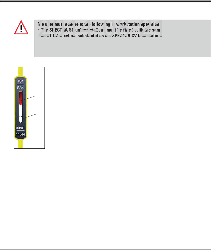
97
Leica HistoCore SPECTRA ST
6. Daily Instrument Setup
Fig. 90
1
2
The current process status of both instruments
can be shown on the screen of the SPECTRA ST.
To switch between the SPECTRA ST and
SPECTRA CV displays, press the "SPECTRA
CV" button in the process status (5, Fig. 16).
The view then changes to the SPECTRA CV
status display (Fig. 89).
In addition to the SPECTRA CV process sta-
tus, messages are also shown on the screen
that pertain to the workstation operation or
SPECTRA CV.
To return, press the "SPECTRA ST" (1, Fig. 89)
button.
The illustration of individual racks in the
workstation operation displays the process
sequences in both the SPECTRA ST and SPEC-
TRA CV. This display is illustrated in two parts.
The upper section (1, Fig. 90) shows the pro-
cess sequence in the SPECTRA ST.
The lower range (2, Fig. 90) shows the process
sequence in the SPECTRA CV.
6.7.5 Operation as a workstation (continued)
The user must adhere to the following in workstation operation!
The SPECTRA ST unload stations must be filled with the same reagent (xylene or Lei-
ca ST Ultra xylene substitute) as the SPECTRA CV load station(s).
Each reagent added must be compatible with the mountant used.
Filling the load and unload station with the same reagent is absolutely necessary in
order to prevent sample losses due to drying out in the case of instrument faults.
DRAFT
DRAFT
DRAFT
6
The user must adhere to the following in workstation operation!
The SPECTRA ST unload stations must be filled with the same
ca ST Ultra xylene substitute) as the SPECTRA CV load station(
2014 08 21
2014 08 21
98 Instructions for Use V 0.5 RevC - 08/2014
7. Cleaning and Maintenance
General instructions
Before each cleaning, shut down the instrument using the operating switch and then
switch it off using the power switch!
No liquid may come into contact with the electrical connections or spill into the inte-
rior of the instrument or the housing below the transport arms!
When using cleaning agents, observe the manufacturer's safety instructions and the
laboratory regulations valid in the country of use.
Dispose of spent reagents in accordance with the laboratory guidelines in force in
your country!
The following applies to all instrument surfaces:
Wipe up spilled solvents (reagents) without delay! The lid surfaces only have moder-
ate resistance in the event of prolonged contact with solvents!
Do not use any of the following for cleaning the outside surfaces of the instrument:
alcohol, detergents containing alcohol (e.g. window cleaner), abrasive cleaning pow-
ders, solvents containing acetone or xylene.
7.1 Important notes about this instrument cleaning
7.1.1 Exterior surfaces, varnished surfaces, instrument cover
The surfaces can be cleaned with a mild, pH-neutral, commercially available cleaning agent.
After cleaning the surfaces, wipe them off with a cloth moistened with water.
Varnished instrument surfaces and plastic surfaces (e.g. an instrument cover) may not
be cleaned with solvents like acetone, xylene, toluene, xylene substitutes, alcohol, al-
cohol mixtures and abrasives! In case of long-term exposure, the surfaces and instru-
ment hood are only conditionally resistant to solvents.
Clean the screen using a lint-free cloth. A suitable screen cleaner can be used in compliance
with the manufacturer information.
7.1.2 TFT touchscreen
DRAFT
DRAFT
DRAFT
n
ance
nance
2014 08 21
eral instructions
efore each cleaning, shut down the instrument using the operat
witch it off using the power switch!
2014 08 21
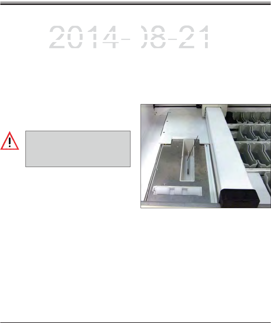
99
Leica HistoCore SPECTRA ST
7. Cleaning and Maintenance
7.1.3 Interior and drain pan
To clean the interior and the drain pan, remove the
reagent cuvettes and water flow cuvettes. Use a
mild, pH-neutral, commercially available cleaning
agent to clean these areas. After cleaning the
drain pan, rinse it thoroughly with water.
7.1.4 Transport arms
To clean the surfaces of the transport arms,
these are to be wiped off with cloth moistened
with water.
7.1.5 Reading module for specimen slides
Check the recess of the specimen slide reading
module for dirt and reagent residue. When us-
ing specimen slides that already have damaged
edges, it is possible that (1, Fig. 91) small glass
shards and splinters have collected. Therefore,
all dirt in this area must be carefully removed to
prevent injury.
1
Fig. 91
Ensure that no liquids spill under-
neath the housing of the transport
arms because there are sensitive
parts here.
DRAFT
DRAFT
DRAFT
7.
C
2014-08-21
o
r and the drain
p
an, remove the
or and the drain pan, remov
a
nd water flow cuvettes. Use a
d water flow cuvettes. Use a
o
mmerc
i
a
ll
y ava
il
a
bl
e c
l
ean
i
ng
ommercially available clea
C
heck the recess of the
sCheck the recess of the s
m
odule for dirt and rea
gmodule for dirt and reag
i
ng spec
i
men s
lid
es t
h
at
ing specimen slides that
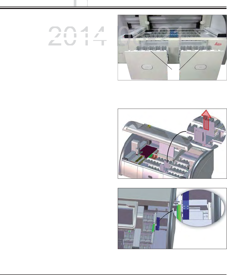
100 Instructions for Use V 0.5 RevC - 08/2014
7. Cleaning and Maintenance
7.1.6 Input and output drawers
Remove reagent cuvettes from both drawers
and store them outside of the instrument.
Check the inside of the drawers for reagent
residue and remove where appropriate.
Finally, insert the reagent cuvettes into the
correct positions again.
Observe the existing labeling (1, Fig. 92) for
stations in the drawers.
7.1.7 Dry transfer station
After inserting the dry transfer station, the
reagents can drip down. This residue must be
removed regularly.
To do so (1, Fig. 93), remove the insert of the
dry transfer station by pulling upwards, check
for contamination and clean if necessary.
Then, re-insert the insert and make sure it
snaps in correctly.
7.1.8 Transfer station (optional)
Check the transfer station regularly for reagent
residue and clean if necessary.
1
Fig. 92
Fig. 93
Fig. 94
DRAFT
DRAFT
DRAFT
n
ance
nance
2014-
c
uvettes
f
rom both drawers
uvettes from both drawe
ts
i
de
o
f th
e
in
s
tr
u
m
e
nt
.de of the instrument
o
f the drawers for reagent
of the drawers for reagen
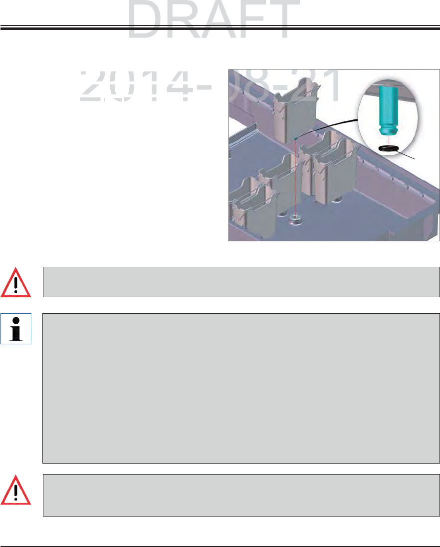
101
Leica HistoCore SPECTRA ST
7. Cleaning and Maintenance
Remove the cuvettes individually from the
clip. Ensure that the clip is in the correct
position (see Chap. 6.2.1) to prevent spilling
the reagent.
The sealing ring (1, Fig. 95) must remain at-
tached to the water flow cuvette.
Dispose of reagents in accordance with the
local laboratory specifications.
All cuvettes can be cleaned in a dishwasher,
at a maximum temperature of 65 °C, using a
standard, commercially available detergent
for lab dishwashers. In doing so, the clip can
remain attached to the various cuvettes.
7.1.9 Reagent cuvettes, rinsing water cuvettes and heated cuvettes (optional)
Never clean the plastic reagent cuvettes at temperatures higher than 65 °C since it can cause
the reagent cuvettes to become deformed!
Fig. 95
If the cleaned and filled reagent cuvettes need to be put back into the instrument, they need to
be put in the correct position in accordance with the displayed arrangement of the bathlayout
(see Fig. 56 in Chap. 5.9.9). To do so, switch on and initialize the instrument.
The water flow cuvettes are to be regularly checked for calcification, visible, microbiologi-
cal deposits of bacteria, fungi, algae and permeability. Lime residue can be removed using a
mild vinegar-based cleaning solution. Finally, rinse off the cuvettes with clear water until the
cleaning agent residue has been removed.
After cleaning the water flow cuvettes and before inserting them into the instrument again,
the connecting piece to the water supply system must be checked for correct positioning on
the black O-ring (see 1, Fig. 95).
If an O-ring is missing or not positioned correctly, the water flow cuvettes may not be put
back into position after cleaning, because otherwise there is a danger of the rinsing function
being defective during the staining process.
After attaching the O-ring or correcting its position, the water flow cuvettes can be put back
into position.
1
DRAFT
DRAFT
7.
C
2014-08-21
uvettes individually from the
uvettes individually from
h
at t
h
e c
li
p
i
s
i
n t
h
e correct
at the clip is in the correct
ChapChap
621621
) to prevent spilling) to prevent sp
08-21
102 Instructions for Use V 0.5 RevC - 08/2014
7. Cleaning and Maintenance
The rack is to be checked regularly for staining residue and other possible contamination.
The stained clip must be removed from the rack for cleaning.
To remove staining reside from the rack, immerse it in a bath of lukewarm water and a mild,
pH-neutral lab cleaner and let the cleaner take effect. When doing so, carefully observe
the additional manufacturer information regarding cleaning agents and the recommended
application area.
Then, strong staining contamination can be removed using a brush.
Now, take your time to thoroughly rinse off the racks with fresh water until no more staining
and cleaning agent residue remains.
If residue from the mountant remains on the racks, these can be placed in a bath of solvent.
The rack and clip may not remain in the solvent for a long time frame (e.g. several hours
or overnight), because this can lead to deformities!
It is essential to ensure that the solvent being used is compatible with the mountant.
Xylene or toluene-based mountants can be removed using a xylene bath. Xylene sub-
stitute-based mountants are removed using a bath containing a corresponding xylene
substitute.
The maximum exposure time in a solvent bath is 1-2 hours. The solvent can be washed
off with alcohol. Completely rinse the rack racks with water, then dry. If an additional
drying oven is used, a temperature of 70 °C may not be exceeded.
7.1.10 Rack and clip
DRAFT
DRAFT
DRAFT
n
ance
nance
2014-08-21
t
o be checked regularly for staining residue and other pos
sto be checked regularly for staining residue and other poss
clip must be removed
f
rom the rack
f
or cleaning.
clip must be removed from the rack for cleaning.
staining reside from the rack immerse it in a bath of lukewarstaining reside from the rack immerse it in a bath of lukewar
103
Leica HistoCore SPECTRA ST
7. Cleaning and Maintenance
7.1.11 Water drain
Image of procedure!
Fig. 96
Image of sieve!
Fig. 97
The draining system within the in-
strument must be regularly cleaned
and checked for correct flow. If this
measure is not completed, the water
draining system must become clogged,
which could lead to interruptions or
malfunctions in the staining process.
To clean the water draining system, remove
the 4 rear water flow cuvettes and all sur-
rounding reagent cuvettes.
The remaining cuvettes must be covered.
Remove the drainage sieve and clean if neces-
sary Fig. 97.
Place one to two cleaning tablets with active
oxygen (e.g. a denture cleanser) into the drain-
age and dissolve in water to remove various
residue (reagents, bacteria, fungi, algae).
Then, clean the entire curved drainage inside
the instrument with a long, flexible brush
Fig. 96.
Check the flow by flushing thoroughly with
water.
Insert the drainage sieve again, and put the cu-
vettes back in their original, defined positions.
DRAFT
DRAFT
DRAFT
7.
C
2014-08-21
08-21
aining system within the
t must be regularly cleaned
ecked for correct flow If
2014-
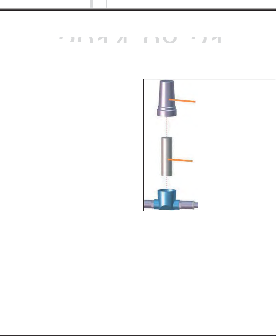
104 Instructions for Use V 0.5 RevC - 08/2014
7. Cleaning and Maintenance
7.1.12 Water drain hose
The water drain hose must be checked once a year by a service technician authorized by Leica.
The integrated water intake filter included with
the instrument protects instrument's internal
water circuit components from damage due to
sediments and mineral deposits.
The water intake filter should therefore be
checked regularly and, when discolorations are
visible due to deposits, washed out or replaced
if necessary.
To do so, shut off the water inlet.
Unscrew the upper filter housing by rotating
the filter housing.
Pull out the filter insert and wash it out or insert
a new filter insert if necessary.
Re-attach and screw the filter housing.
Reopen the water inlet.
Filter housing
Filter cartridge
Order No.: 14 0512 49332
Fig. 98
7.1.13 Water intake filter – changing the filter cartridge
DRAFT
DRAFT
DRAFT
n
ance
nance
2014-08-21
must
b
e
must be
c
h
ec
k
e
d
once a year
b
y a serv
i
ce tec
h
n
i
c
i
an aut
hhecked once a year by a service technician auth
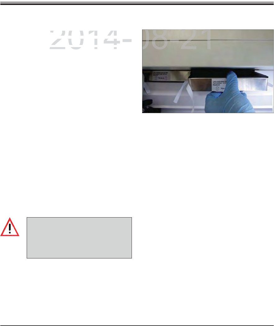
105
Leica HistoCore SPECTRA ST
7. Cleaning and Maintenance
The active carbon filters installed in the instru-
ment helps reduce the amount of reagent vapors
in the exhaust air. The life cycle of the filter can
fluctuate strongly depending on intensity of use
and the reagent configuration of the instrument.
Therefore, replace the active carbon filter regu-
larly (every 2-3 months) and dispose of it proper-
ly in accordance with the laboratory regulations
applicable in the country of use.
The filter unit consists of two individual filter
elements (Fig. 99), which are accessible to the
user on the front of the instrument.
They can be accessed without tools and re-
moved by pulling on the pull tabs.
Insert the new filter elements in an inverted
direction and in the same way so that the pull
tabs can also be seen and reached after push-
ing in completely and the printed-on arrow
points upwards.
Both active carbon filters must be pushed in
until you feel them make contact with the rear
panel of the instrument.
Fig. 99
7.1.14 Replacing the active carbon filter
If inserted incorrectly, the active car-
bon filters can extend into the range
of movement of the two transport arms,
impeding or interrupting the staining
process.
DRAFT
DRAFT
DRAFT
7.
C
2014-08-21
n
filters installed in the instr
un filters installed in the in
-
e
the amount o
f
reagent vapors
the amount of reagent vapors
The life cycle of the filter canThe life cycle of the filte
08-21
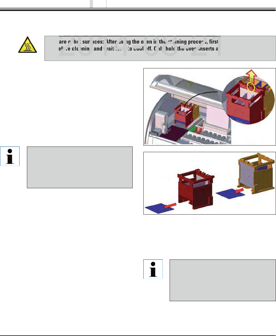
106 Instructions for Use V 0.5 RevC - 08/2014
7. Cleaning and Maintenance
Beware of hot surfaces: After using the oven in the staining process, first switch the instrument
off before cleaning and wait for it to cool off. Only hold the oven inserts at the described posi-
tions.
7.1.15 Cleaning the ovens
Fig. 100
1
1
2
23
3
Regularly clean the sheet metal inserts for catch-
ing paraffin residue in the oven for dirt.
Fold the moving oven cover up and to the left,
(1, Fig. 100) then pull it towards the front of the
instrument.
Grasp both connected oven chambers in the
center (2, Fig. 100+101) and pull them upwards.
Fig. 101
The interior of the oven must not be
cleaned using solvents, as there is a
risk that solvent residues will get into
the oven and evaporate in the oven
when the process begins.
For safe transport, after pulling out the
two oven chambers that are still con-
nected, stabilize them on the bottom
by grasping them with your flat hand.
Disconnect the two oven chambers by pulling
them up in opposite directions.
You can then pull out the insert for catching
paraffin residue from the respective oven
chamber (3, Fig. 101).
Check the sheet metal inserts for paraffin resi-
due and dirt. To melt the paraffin, the inserts
can be placed in an external laboratory oven.
After heating, wipe off the paraffin residue
with a lint-free cloth.
Check the ventilation flaps in the oven cham-
bers for proper function. If they are visibly
dirty, carefully clean them with a lint-free
cloth.
Push the sheet metal insert into the respective
oven chamber, facing the right way.
Put both oven chambers back together and
insert them into the instrument.
DRAFT
DRAFT
DRAFT
n
ance
nance
2014 08 21
of hot surfaces: After using the oven in the staining process, first s
efore cleaning and wait for it to cool off. Only hold the oven inserts at
s
2014 08 21
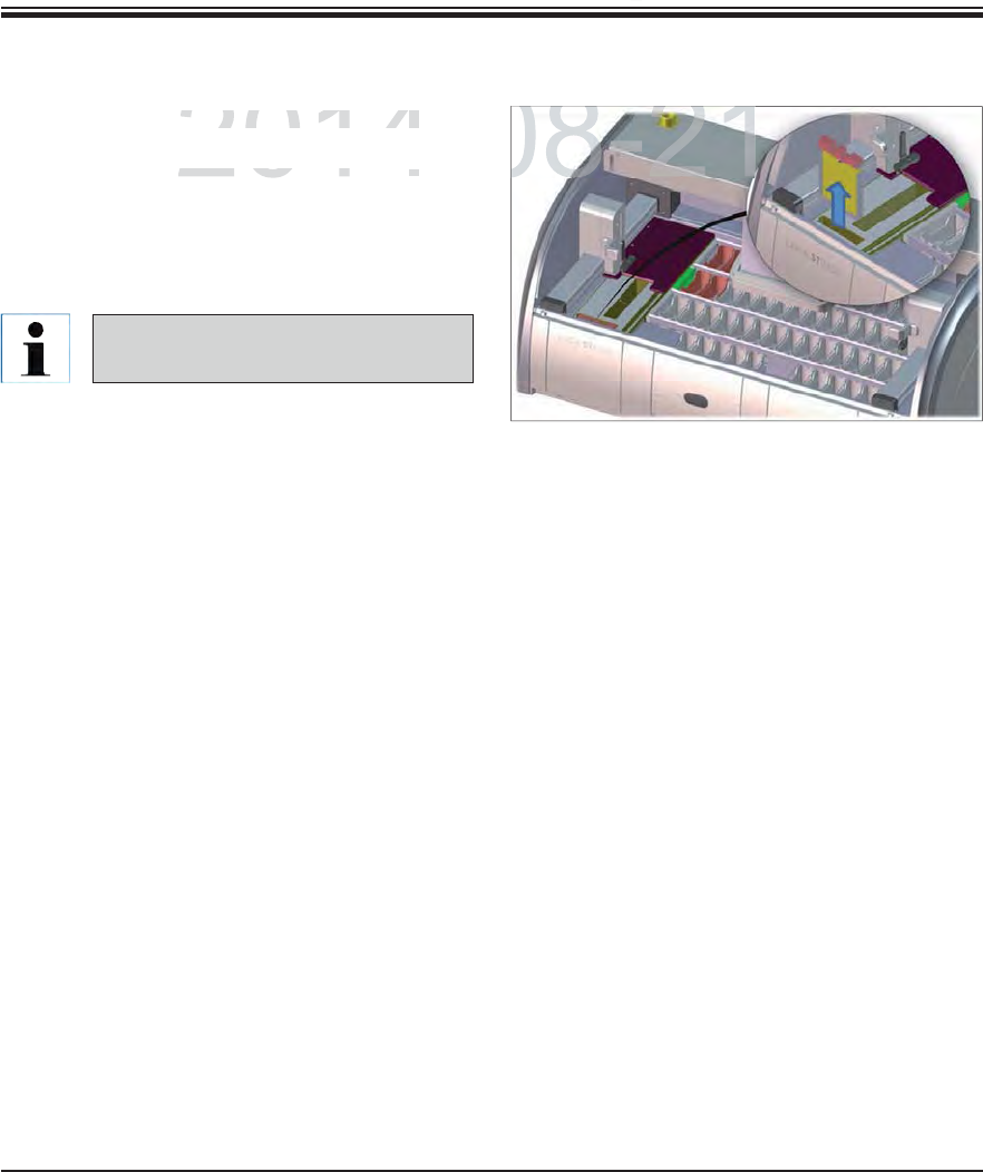
107
Leica HistoCore SPECTRA ST
7. Cleaning and Maintenance
The air filter of the oven should be checked and
cleaned regularly.
To do so, remove the filter insert (1, Fig. 102)
and shake it out.
After checking and cleaning, re-insert into the
oven in the same way.
The installation is carried out in re-
verse order.
7.1.16 Oven air filter
Fig. 102
DRAFT
DRAFT
DRAFT
7.
C
2014-08-21
e
oven should be checked and
e oven should be checked
ove the filter insert (ove the filter inser
1
Figg
102
)
08-21
108 Instructions for Use V 0.5 RevC - 08/2014
7. Cleaning and Maintenance
7.2 Recommended maintenance and cleaning intervals
To ensure trouble-free operation of the instrument over a long period of time, the following is
strongly recommended:
You must carry out the maintenance and cleaning tasks listed below.
Have the instrument checked at least once a year by a qualified service technician autho-
rized by Leica.
At the end of the warranty period, enter into a service contract. For more information, contact
the relevant customer service organization.
Daily cleaning and maintenance
If sensitive instrument parts and areas get very dirty or if reagents are spilled,
they must be cleaned immediately, as otherwise a reliable workflow is not
guaranteed.
Task Refer also to
Checking and filling/refilling the reagent cuvettes. Chap. 6.2.1
Covering the reagent cuvettes and, if necessary, storing them with
covers in the refrigerator.
Checking the rack and clips for paraffin or dye residue and broken glass. Chap. 7.1.10
Check the slide reader module for reagent residue and clean it if
necessary.
Chap. 7.1.5
Check the housing in the area of the input and output drawers for solvent
residue and clean it if necessary.
Chap. 7.1.6
Check the transfer station (optional workstation) (Fig.) for solvent resi-
dues and clean if necessary.
Chap. 7.1.8
Clean the insert of the dry transfer station and clean if necessary. Chap. 7.1.7
DRAFT
DRAFT
DRAFT
n
ance
nance
2014-08-21
ble-free operation of the instrument over a long period of t
ble-free operation of the instrument over a long period of t
men
d
e
d:mended
arry out the maintenance and cleaning tasks listed belowarry out the maintenance and cleaning tasks listed belo

109
Leica HistoCore SPECTRA ST
7. Cleaning and Maintenance
Task Refer also to
Checking/cleaning the water flow cuvettes for bacterial contamination
and checking the sealing rings to make sure that they are present
Chap. 7.1.9
Cleaning the reagent cuvettes Chap. 6.2.1
Checking/cleaning the heated reagent cuvettes Chap. 7.1.9
Cleaning the racks and clips. Chap. 7.1.10
Check the water drain and sieve within the instrument for proper func-
tion and clean it if necessary.
Chap. 7.1.11
Checking transport arms for dirt and clean if necessary. Chap. 7.1.4
Weekly cleaning and maintenance
Task Refer also to
Checking the water intake filter and changing it if necessary. Chap. 7.1.13
Checking and cleaning the air filter of the drying oven. Chap. 7.1.16
Cleaning the drip tray. Chap. 7.1.3
Checking the drying oven insert and catch tray for paraffin residue
and cleaning it.
Chap. 7.1.15
Monthly maintenance and cleaning
Cleaning and maintenance as necessary
Task Refer also to
Clean the screen using a lint-free cloth. A screen cleaner can be used
according to manufacturer instructions.
Chap. 7.1.2
Cleaning outer/painted surfaces Chap. 7.1.1
Instrument cover Chap. 7.1.1
DRAFT
DRAFT
DRAFT
7.
C
2014 08 21
2014 08 21
2014-08-21
he screen using a lint-free cloth. A screen cleaner can be us

110 Instructions for Use V 0.5 RevC - 08/2014
Task Refer also to
Checking and maintenance of the instrument by a service technician
authorized by Leica.
Task Refer also to
Changing the active carbon filter. Chap. 7.1.14
Quarterly cleaning and maintenance
Annual maintenance and cleaning
7. Cleaning and Maintenance
Task Refer also to
Replace the water intake filter. Chap. 7.1.13
Cleaning and maintenance every six months
DRAFT
DRAFT
DRAFT
n
ance
nance
2014-08-21
2014-08-21
he active carbon filter.

111
Leica HistoCore SPECTRA ST
8. Malfunctions and Troubleshooting
Error/problem Cause Troubleshooting
Rising water level in the drain
pan with alarm.
Water drain partially or com-
pletely blocked
Checking and maintaining the water
drain hose. For this purpose, contact
the responsible Leica service.
Water drainage system in-
side the instrument and/or
the drainage sieve partially or
completely blocked.
Checking and maintaining the water
drain system in the instrument.
Observe the cleaning instructions in
Chap. 7.1.11.
Observe regular maintenance in-
tervals.
If the blockage remains, the water
inflow to the water flow cuvettes is
stopped and the staining process is
interrupted. Therefore, the speci-
mens have to be removed from the
instrument and brought to a safe
position or temporary storage (see
warning message in Chap. 8.2).
Decreased flushing during the
staining cycles with possibly
inconsistent staining results.
Water inlet in water flow cu-
vettes attenuated/blocked.
Possible causes:
Water flow cuvettes fit in-
correctly (note O-ring).
Calcification of the water
flow cuvette.
Monitoring and maintaining the
water flow cuvettes.
Observe the cleaning instructions
in Chap. 7.1.9.
Observe regular maintenance in-
tervals.
Water flow cuvettes do not
drain automatically during
breaks in operation of the in-
strument. Standing water can
be a source for microbiologi-
cal contamination in the water
flow cuvette and the samples.
The additional water drain hole
at the base of the water flow
cuvettes is blocked by calcifi-
cation/dirt.
Monitoring and maintaining the
water flow cuvettes.
Observe the cleaning instructions
in Chap. 7.1.9.
Observe regular maintenance in-
tervals.
8.1 Fault remedies for instrument malfunctions
DRAFT
DRAFT
DRAFT
8
.
.
Malfun
c
Malfu
2014-08-21
C
aus
eCau
Troubleshoo
tTroubleshoot
l
i
n t
h
e
d
ra
i
n
l in the drain
Water drain
p
artiall
y
or co
mater drain partially or com
- Checkin
g
an
dhecking and

112 Instructions for Use V 0.5 RevC - 08/2014
8. Malfunctions and Troubleshooting
Error/problem Cause Troubleshooting
Insufficient flushing during the
staining processes may yield
inconsistent staining results.
Water pressure too low in the
intake drainage system of the
lab or fluctuations at different
times of the day
The specified minimum require-
ments for water pressure (see
Chap. 3.2) must be fulfilled (even
for possible deviations during the
daytime).
Plastic cuvettes are deformed. Use of reagents that are not
permitted (ex. phenol in Ziehl-
Neelson dye or Gram dye, etc.).
Incorrectly applied cleaning
procedure.
Monitoring the used reagents using
the list of permitted reagents (see
Appendix 1).
Observe the cleaning instructions
in Chap. 7.1.9.
Inconsistent staining results The tolerance of the program
step for staining reagents is not
correctly defined.
Inspecting the staining protocols
and reagents.
Most short program steps demand
exact compliance with the staining
step. The tolerance of the reagent
must be set to 0 %.
Varying staining results The process classes (paraffin
removal, stainers, differentia-
tion, etc.) for reagents were not
correctly assigned. This means
that the bathlayout might not
have been optimally created.
Inspecting and correcting the as-
signed reagent classes based on
Chap. 5.8.1
Reagents that are only to be
used by one program are used
by other programs. The reagent
is dirty because it was not pro-
grammed as "Exclusive".
Inspecting and correcting the pro-
gramming of respective reagents.
8.1 Fault remedies for instrument malfunctions (continued)
DRAFT
DRAFT
DRAFT
u
bleshootin
g
ubleshooting
2014-08-21
C
ause
Cause
Troubleshootin
gTroubleshooting
d
urin
g
the
during the
Water
p
ressure too low in the
Water pressure too low in the
The s
p
ecified
The specified m

113
Leica HistoCore SPECTRA ST
8. Malfunctions and Troubleshooting
Error/problem Cause Troubleshooting
After drying, tissue does not
adhere well enough to the
slide, and floats away during
the staining process.
For customer-defined program
protocols, the selected firing
time and oven temperature (or
both) are too low.
Inspecting and correcting infor-
mation about firing time and oven
temperature for customer-defined
protocols.
The staining processes are
complete, but repeated or
additional programming (su-
pervisor mode) cannot be
completed.
Programming can only be com-
pleted when the instrument is in
sleep mode; in other words, no
racks may be in the process;
this also includes the positions
of the output drawer.
Remove racks from the output draw-
er, then carry out programming.
Initialization of the instrument
cannot be completed.
Arms are blocked. Check that the active carbon filter
is in the correct position.
8.1 Fault remedies for instrument malfunctions (continued)
DRAFT
DRAFT
DRAFT
8
.
.
Mal
f
un
c
Malfu
2014-08-21
C
aus
eCau
Troubleshoo
tTroubleshoot
u
e does not
ue does not
For customer-defined
p
ro
g
ram
r customer-defined program
Ins
p
ectin
g
aspecting a

114 Instructions for Use V 0.5 RevC - 08/2014
8. Malfunctions and Troubleshooting
In case of a temporary power failure (under 5 seconds), the instrument will continue to be
operated without interruption via an internal output buffering.
However, all staining programs are canceled if there is a longer-term power failure for more
than 5 seconds. A rack located in the transfer is attached to the closest possible secure
position between the reagent stations. This is done to prevent accidental lowering into a
reagent not compatible with the program.
Afterwards, the rack must be removed from the transfer arm (Fig. 104).
This occurrence is saved in the results protocol (see Chap. 5.7.9).
All racks within the process must be removed from the instrument by hand. Also be sure to
check the following positions on the rack and remove if necessary:
- Reader module for specimen slides (see 2, Fig. 4)
- Oven (see 10, Fig. 4)
- Transfer station for SPECTRA CV (see 6, Fig. 4)
Make sure that the specimens are stored outside of the instrument in a suitable reagent
and that the steps of the current staining protocol are continued to the end of the protocol
manually. The user shall be responsible for further processing of the samples.
After the power supply is restored, the instrument can be restarted and loaded with new
specimens.
Image, removal of rack from the
transfer arm during power failure
Fig. 104
8.2 Power failure scenario
DRAFT
DRAFT
DRAFT
u
bleshootin
g
ubleshooting
2014-08-21
a
temporary power failure
(
under
5 temporary power failure (under
seconds
)
, the instrumen
seconds), the instrumen
i
thout interruption via an internal output bu
ff
ering
.thout interruption via an internal output buffering.
ll staining programs are canceled if there is a longer term poll staining programs are canceled if there is a longer term po
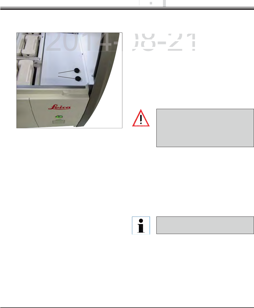
115
Leica HistoCore SPECTRA ST
8. Malfunctions and Troubleshooting
8.3 Replace main fuses
The instrument should be switched off using the
power switch and disconnected from the power
supply in the case of a instrument failure. The
main fuses can then be inspected.
To do so, open the hood and unscrew the
two fuse holders on the top of the right cover
(1, Fig. 103) with a flat-head screwdriver and
check for damage.
Fig. 103
1
A suitable flat-head screwdriver must
be used to prevent damage to the fuse
holder.
Beware of defective fuses! Potential
risk of injury due to broken glass!
If the fuse is defective, remove it from the fuse
holder and replace it with a new fuse.
Installation occurs in the reverse sequence
of operations.
Only fuses with a T16 A H 250 V AC
fuse rating can be used.
DRAFT
DRAFT
DRAFT
8
.
.
Mal
f
un
c
Malfu
2014-08-21
The instrument should b
eThe instrument should be
power switch and disco
npower switch and discon
supply in the case of asupply in the case of a
2014-
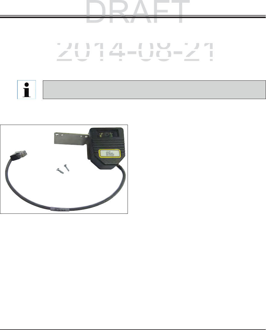
116 Instructions for Use V 0.5 RevC - 08/2014
9. Instrument Components and Specifications
Fig. 105
9.1 Optional instrument components
The SPECTRA ST slide stainer can be equipped with the following optional modules. A subse-
quent equipment configuration with one or more of the options listed below is possible. Note
that retrofitting also incurs a fee for a service call that can result in additional costs along with
the option costs.
Using the slide reader module, specimen slides
with printed barcodes can be read out and the
information can be sent to a LIS network system
connected to the instrument.
Note that specimen slide labels can be read us-
ing this module only if they contain the following
properties:
Barcode types:
1D barcode: Code 128, up to 8 characters
1D barcode: CODABAR, up to 8 characters
2D barcode: Datamatrix, 17 mil. resolution, up
to 30 characters
2D barcode: QR code, min. 21x21, max. 30x30
elements
The print quality of the specimen slide label must
at least conform to the quality level 2 (C) in ac-
cordance with ISO 15416 and EN797.
Order No. 14 0512 47193
Reader module for specimen slides
The component(s) must only be subsequently installed by Leica certified service techni-
cians. This can result in additional costs.
DRAFT
DRAFT
ts and
Sp
ecification
s
ts and Specification
p
2014-08-21
S
T slide stainer can be equipped with the following option
aST slide stainer can be equipped with the following optiona
nt con
f
iguration with one or more o
f
the options listed bel
ont configuration with one or more of the options listed belo
also incurs a fee for a service call that can result in additioalso incurs a fee for a service call that can result in additio
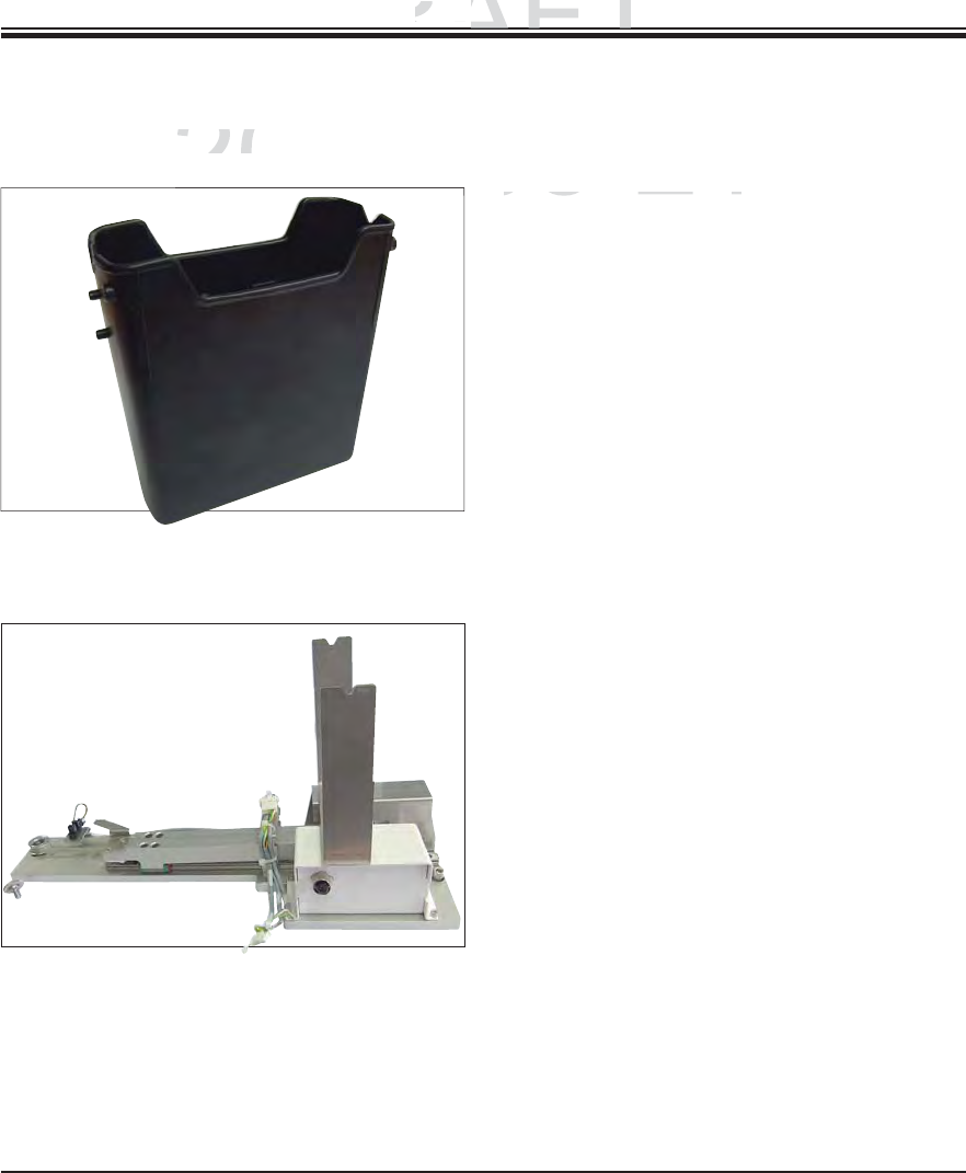
117
Leica HistoCore SPECTRA ST
9. Instrument Components and Specifications
9.1 Optional instrument components (continued)
Fig. 106
Fig. 107
Module with four individually heated reagent
cuvettes, 380 ml
Heated reagent cuvettes can individually heat up
to 4 reagents used for special dyes.
The module includes 4 heatable reagent cuvettes
that replace 4 unheated plastic reagent cuvettes.
The list of usable reagents (see Appendix 1) must
be observed.
Order No. 14 0512 47509
Leica SPECTRA CV: for use in the SPECTRA ST,
transferring samples to a connected robotic
coverslipper
When integrating a SPECTRA CV robotic cover-
slipper, this module is used as a workstation. It
transfers the specimen slide automatically from
the staining machine into the robotic coverslipper.
Order No.: 14 0512 47395
Heated reagent cuvettes
Transfer module for racks
DRAFT
DRAFT
DRAFT
9
.
9.
Instrument
C
om
p
Instrument Com
2014-08-21
2014
M d l ith f i di iM d l ith f i di i
c
uvettes
cuvettes
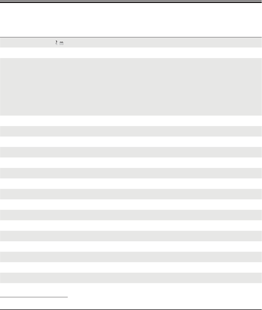
118 Instructions for Use V 0.5 RevC - 08/2014
9.2 Optional Accessories
Specimen slide*
Designation Order No.
Outlet hose, length: 2 m 14 0475 35747
Supply hose for rinsing water 14 0474 32325
Water connection kit with filter
Supply hose 3, length: 1.5 m extension
Y piece
Double nipple G3/4 G3/8
Water filter housing
Filter cartridge
Bushing G3/4
14 0512 49324
14 0512 49334
14 3000 00351
14 3000 00350
14 0512 49331
14 0512 49332
14 3000 00360
Exhaust hose, length 2 m 14 0475 35762
Active carbon filter 14 0512 47131
Reagent cuvette, assembly, including reagent cuvette cover 14 0512 47086
Water flow cuvette assembly 14 0512 47087
Used for special dyes (only for racks designed for up to 5 specimen slides) 14 0512 49261
Rack for 30 specimen slides* (3 pcs. per package) 14 0512 52473
Rack 5 specimen slides* (3 pcs. per package) 14 0512 52475
Clip for rack 30 specimen slides* (yellow, 3 pcs. per package) 14 0512 52476
Clip for rack 30 specimen slides* (light blue, 3 pcs. per package) 14 0512 52477
Clip for rack 30 specimen slides* (dark blue, 3 pcs. per package) 14 0512 52478
Clip for rack 30 specimen slides* (pink, 3 pcs. per package) 14 0512 52479
Clip for rack 30 specimen slides* (red, 3 pcs. per package) 14 0512 52480
Clip for rack 30 specimen slides* (light green, 3 pcs. per package) 14 0512 52481
Clip for rack 30 specimen slides* (black, 3 pcs. per package) 14 0512 52482
Clip for rack 30 specimen slides* (gray, 3 pcs. per package) 14 0512 52483
Clip for rack 30 specimen slides* (white, 3 pcs. per package) 14 0512 52484
Clip for rack 5 specimen slides* (yellow, 3 pcs. per package) 14 0512 52494
DRAFT
DRAFT
DRAFT
2014-08-21
2014-08-21
2014-08-21
2014-08-21
2
m
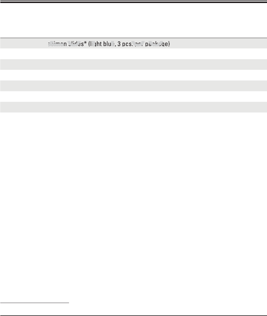
119
Leica HistoCore SPECTRA ST
Designation Order No.
Clip for rack 5 specimen slides* (light blue, 3 pcs. per package) 14 0512 52495
Clip for rack 5 specimen slides* (dark blue, 3 pcs. per package) 14 0512 52496
Clip for rack 5 specimen slides* (pink, 3 pcs. per package) 14 0512 52497
Clip for rack 5 specimen slides* (red, 3 pcs. per package) 14 0512 52498
Clip for rack 5 specimen slides* (light green, 3 pcs. per package) 14 0512 52499
Clip for rack 5 specimen slides* (black, 3 pcs. per package) 14 0512 52500
Clip for rack 5 specimen slides* (gray, 3 pcs. per package) 14 0512 52501
Clip for rack 5 specimen slides* (white, 3 pcs. per package) 14 0512 52502
Specimen slide*
DRAFT
DRAFT
DRAFT
2014-08-21
2014-08-21
2014-08-21
2014-08-21
ecimen slides* (light blue, 3 pcs. per packag
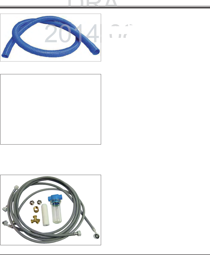
120 Instructions for Use V 0.5 RevC - 08/2014
Fig. 108
Fig. 109
Fig. 1110
Outlet hose,
Length: 2 m
Order No. 14 0475 35747
Supply hose for rinsing water,
Length: 2.50 m assembly with 3/4" connection for
water tap, incl. replacement seal
Order No. 14 0474 32325
Water connection kit with filter
Order No. 14 0512 49324
Supply hose 3,
Length: 1.5 m extension 14 0512 49334
Y piece 14 3000 00351
2x G3/4 G3/8 double nipple 14 3000 00350
Walter filter housing 14 0512 49331
POROPLAST filter cartridge 14 0512 49332
Bushing G3/4 14 3000 00360
9. Instrument Components and Specifications
DRAFT
DRAFT
DRAFT
ts and S
p
ecification
s
ts and Specification
p
-08-21
-
Length:
2
Length: 2
m
m
O
rder No.
Order No
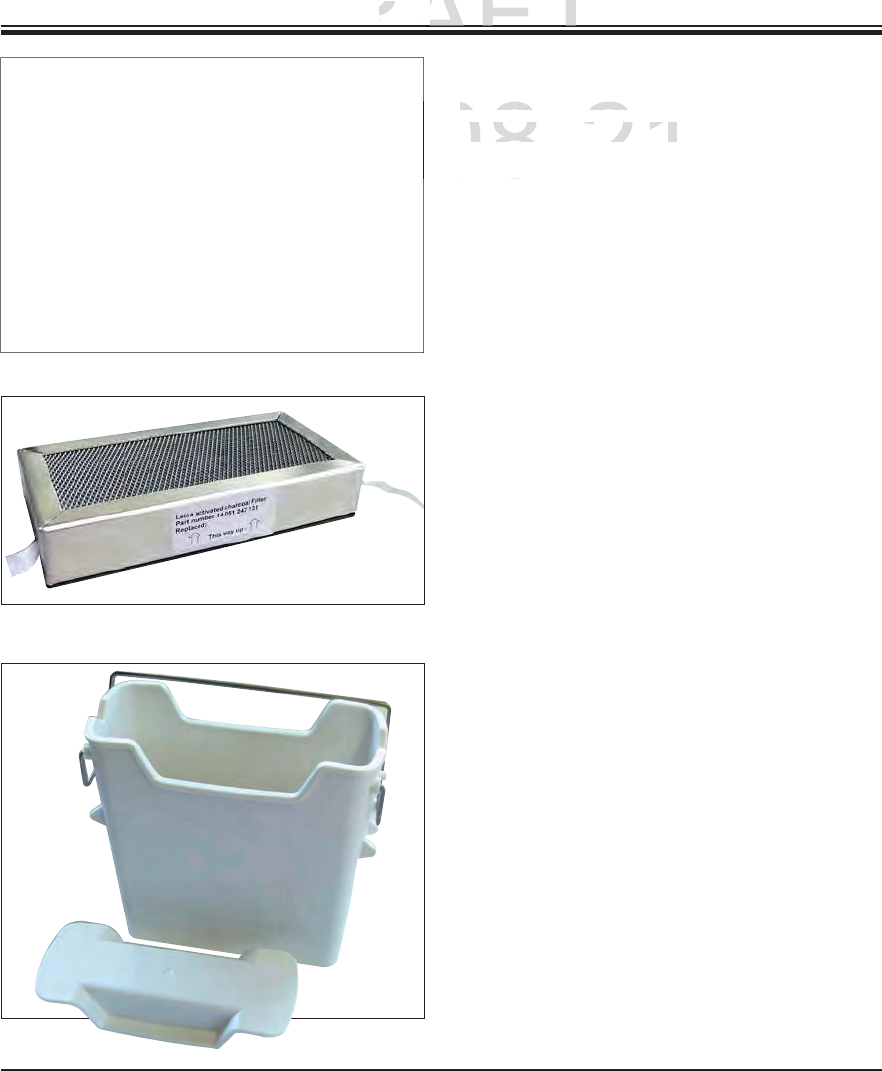
121
Leica HistoCore SPECTRA ST
Fig. 111
Fig. 112
Fig. 113
Exhaust hose,
Length 2 m, assembly,
including adapter for fume hood
Order No. 14 0475 35762
Active carbon filter
Order No. 14 0512 47131
Reagent cuvette
assembly, incl. reagent cuvette cover
Order No. 14 0512 47086
9. Instrument Components and Specifications
DRAFT
DRAFT
DRAFT
9
.
9.
Instrument
C
om
p
Instrument Com
2014-08-21
-
Length
2
Length 2
m
,
assembly
,
semb
including adapter
f
or
f
u
mncluding adapter for fum
Od NOd N
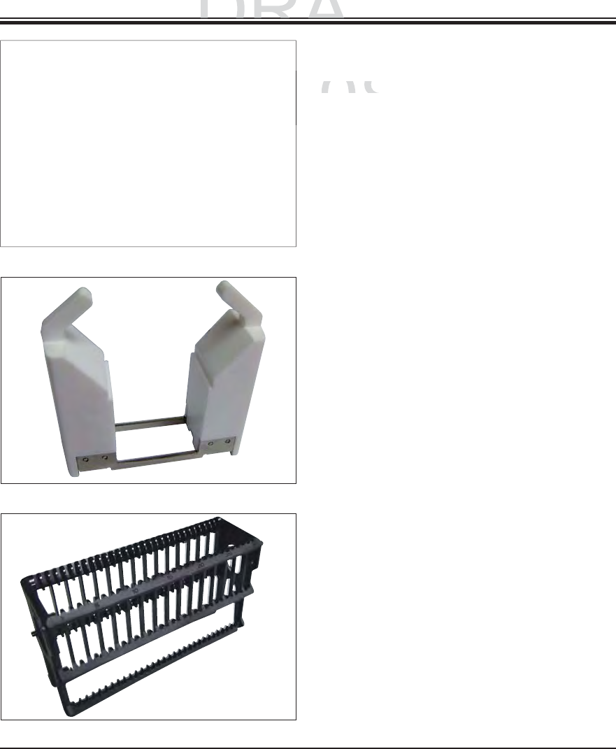
122 Instructions for Use V 0.5 RevC - 08/2014
Fig. 114
Fig. 115
Fig. 116
Water flow cuvette assembly,
Order No. 14 0512 47087
Used for special dyes
(only for racks designed for up to 5 specimen
slides),
Ø 10 mm, length: 2.5 m
Order No. 14 0512 49261
Rack
30 specimen slides* (3 pcs. per package)
Order No. 14 0512 52473
9. Instrument Components and Specifications
DRAFT
DRAFT
DRAFT
ts and
Sp
ecification
s
ts and Specification
p
2014-08-21
-
O
rder No.
Order No.
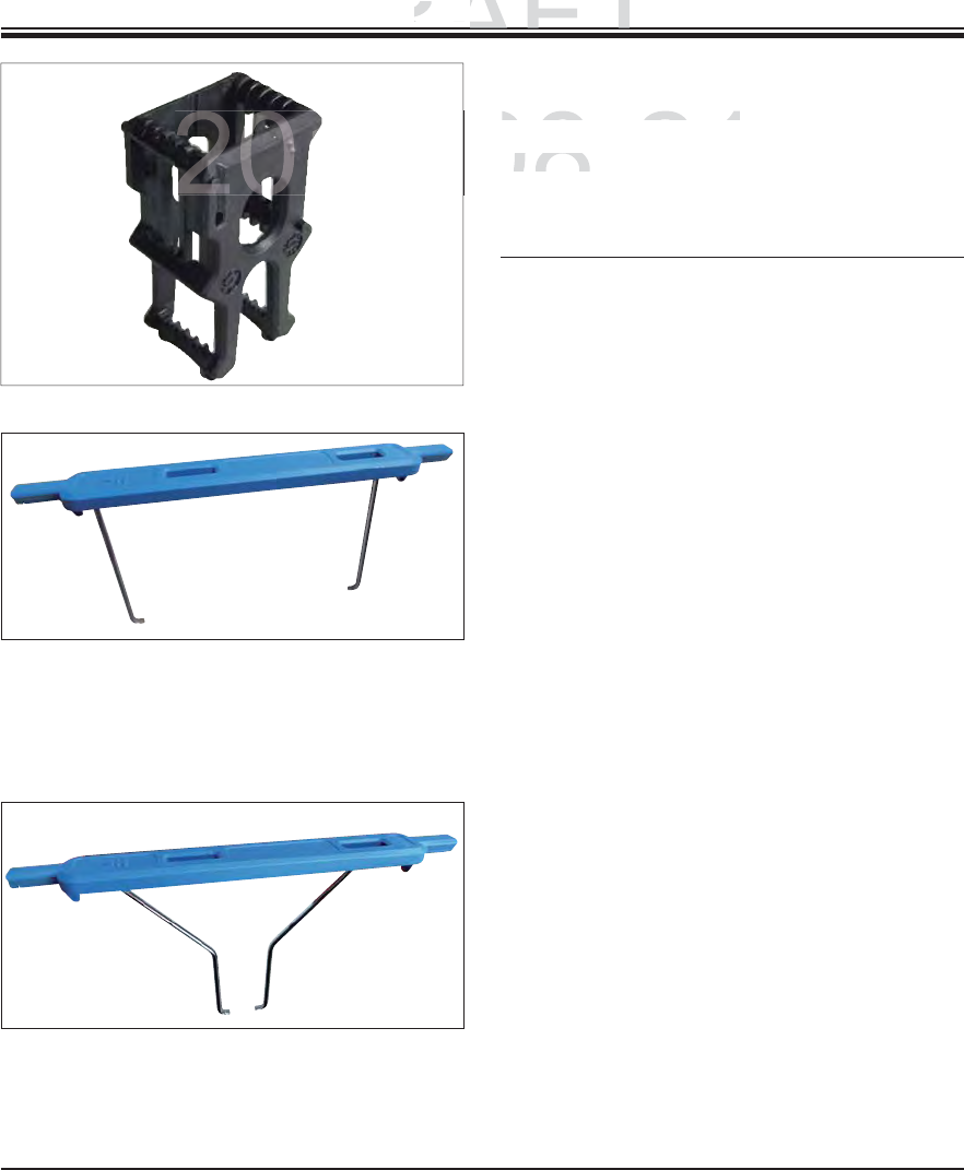
123
Leica HistoCore SPECTRA ST
Fig. 117
Fig. 118
Fig. 119
Rack
5 specimen slides* (3 pcs. per package)
Order No. 14 0512 52475
Clip for rack,
30 specimen slides*, (3 pcs. per package)
yellow 14 0512 52476
light blue 14 0512 52477
dark blue 14 0512 52478
pink 14 0512 52479
red 14 0512 52480
light green 14 0512 52481
black 14 0512 52482
gray 14 0512 52483
white 14 0512 52484
Clip for rack,
5 specimen slides*, (3 pcs. per package)
yellow 14 0512 52494
light blue 14 0512 52495
dark blue 14 0512 52496
pink 14 0512 52497
red 14 0512 52498
light green 14 0512 52499
black 14 0512 52500
gray 14 0512 52501
white 14 0512 52502
Set of slide racks for 5 slides, pack of 3
9. Instrument Components and Specifications
DRAFT
DRAFT
DRAFT
9
.
9.
Instrument Com
p
Instrument Com
2014-08-21
-
5
specimen
slides
(3
pcs
5 specimen slides (3 pcs
Order No
.Order No

124 Instructions for Use V 0.5 RevC - 08/2014
10. Garantie und Service
Warranty
Leica Biosystems Nussloch GmbH guarantees that the contractual product delivered has been sub-
jected to a comprehensive quality control procedure based on the Leica in-house testing standards,
and that the product is faultless and complies with all technical specifications and/or agreed char-
acteristics warranted.
The scope of the warranty is based on the content of the concluded agreement. The warranty terms
of your Leica sales organization or the organization from which you have purchased the contractual
product shall apply exclusively.
Service information
If you are in need of technical customer support or spare parts, please contact your Leica represen-
tative or the Leica dealer where you purchased the instrument.
Please provide the following information:
Model name and serial number of the instrument.
Location of the instrument and name of a contact person.
Reason for the service call.
The delivery date of the instrument.
DRAFT
DRAFT
DRAFT
2014-08-21
ssloch
GmbH
guarantees
that
the
contractual
product
deliv
ssloch GmbH guarantees that the contractual product deliv
nsive quality control procedure based on the Leica in-hou
snsive quality control procedure based on the Leica in-hous
is faultless and complies with all technical specifications
ais faultless and complies with all technical specifications a
dd
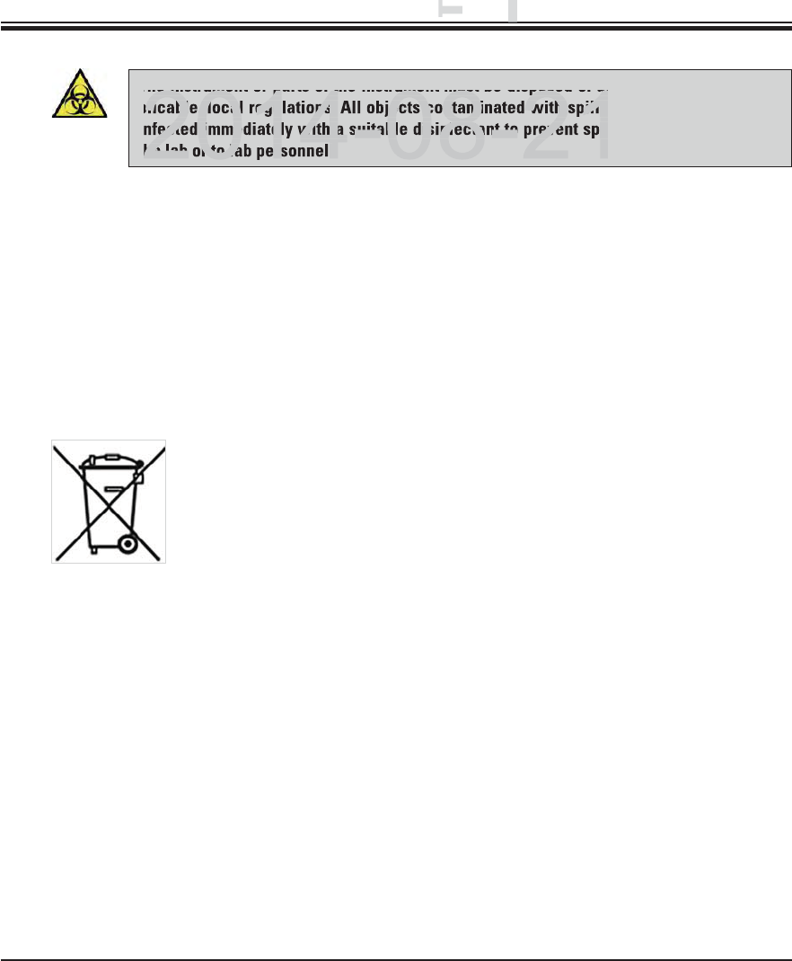
125
Leica HistoCore SPECTRA ST
11. Decommissioning and Disposal
The instrument or parts of the instrument must be disposed of according to existing ap-
plicable, local regulations. All objects contaminated with spilled reagents must be dis-
infected immediately with a suitable disinfectant to prevent spreading to other areas of
the lab or to lab personnel.
Please comply with the Cleaning chapter for notes on cleaning the SPECTRA ST staining ma-
chine.
The instrument can be contaminated when using biohazardous specimens. Thorough disin-
fecting is required before re-commissioning or disposal (e.g. multiple cleaning steps, disinfec-
tion or sterilization). Dispose of the instrument in compliance with the applicable laboratory
specifications.
Contact your Leica representative for more information.
Instrument components such as the computer, monitor, etc. that are la-
beled with the crossed-out dust bin are affected by the European Directive
2002/96/EC for Waste Electrical and Electronic Equipment (WEEE) of the
European Parliament and the Council of January 27, 2003.
These objects must be disposed of via the collection points in accordance
with the local regulations. More information on disposal of the instrument
can be obtained from your local disposal company or your local Leica sup-
port staff.
DRAFT
DRAFT
DRAFT
11.11.
Deco
e
he instrument or parts of the instrument must be disposed of ac
plicable, local regulations. All objects contaminated with spille
fected immediately with a suitable disinfectant to prevent spre
he lab or to lab personnel.
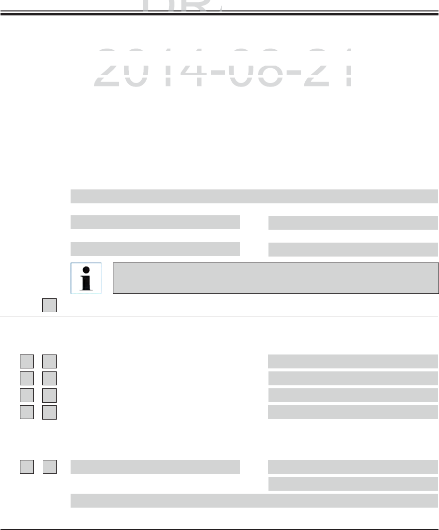
126 Instructions for Use V 0.5 RevC - 08/2014
12. Decontamination Certificate (master)
Dear Customer,
Any product which is to be returned to Leica Biosystems or serviced on site, must be cleaned and decontami-
nated
in the appropriate manner. Since it is not possible to decontaminate against diseases caused by prions such
as CJD, BSE or CWD, instruments that have come into contact with prion-contaminated specimens cannot
be returned to Leica Biosystems for repairs. Prion-contaminated instruments will only be repaired after the
service technician has been made aware of the potential risks, informed about the applicable directives and
procedures for the respective institution, and provided with personal protective equipment. Please complete
this certificate carefully and place a copy with the instrument, attach it to the outside of the transport case or
hand it directly to the service engineer. If packages are returned, they will not be opened or have maintenance
measures begun until the Company or service technician has received confirmation of decontamination. Should
returned goods be considered a hazard by the Company, they will be returned immediately to the customer at
his/her expense.
AThis equipment has not been in contact with unfixed biological samples.
Yes
B
B
Innere o. äußere Bereiche des Gerätes waren folg. gefährl. Substanzen ausgesetzt:
1
Yes No
Yes No
Additional information
Blood, bodily fluids, pathological samples
Other biohazards
Chem. Stoffe/gesundheitsgefähr. Substanzen
Other hazards
2This equipment has been cleaned and decontaminated:
Additional information
If yes, give details of the method:
If no*, please indicate why not:
* Such equipment must not be returned without the written agreement of Leica Biosystems.
Designation
Name/Model Fabr. No.
KAT No. Quantity
Check box A if applicable. Otherwise please complete all parts of B, provid-
ing further information as requested or appropriate.
DRAFT
AFT
DRAFT
ificate (master)
ificate (master)
()
2014-08-21
o
be
returned
to
Leica
Biosystems
or
serviced
on
site,
must
be
cle
be returned to Leica Biosystems or serviced on site, must be cle
n
er.
S
ince it is not possible to decontaminate against diseases
cer. Since it is not possible to decontaminate against diseases c
i
nstruments that have come into contact with
p
rion-contaminat
instruments that have come into contact with prion-contaminat
127
Leica HistoCore SPECTRA ST
Important - to avoid refusal of shipment:
Place one copy in the unit prior to packaging or hand it over to the service engineer. Customer as-
sumes all responsibility for the immediate return shipment of articles sent to Leica without proper
decontamination documentation.
If you have any further questions, please call your local Leica branch office.
Leica Internal Use: If applicable, note corresponding Job and RAN/RGA numbers:
Job Sheet No.: ____________________
SU Return Goods Authorization: ____________________
BU Return Authorization Number: ____________________
Leica Biosystems Nussloch GmbH
Heidelberger Str. 17-19
69226 Nussloch, Germany
Phone: +49 (0) 6224 143 0
Fax: +49 (0) 6224 143 268
Web: www.LeicaBiosystems.com
Signature/Date
Name
Position
E-mail
Institute
Department
Address
Phone Fax
3
Yes No The equipment has been prepared to ensure safe handling/transportation.
Whenever possible, please use the original packaging.
12. Decontamination Certificate (master)
B
DRAFT
DRAFT
DRAFT
1
2.12.
Decontam
i
Deconta
2014-08-21
h
e e
q
ui
p
ment has been
p
re
p
ared to ensure safe handlin
g
/tr
he equipment has been prepared to ensure safe handling/tr
W
henever
p
ossible,
p
lease use the ori
g
inal
p
acka
g
in
g.henever possible, please use the original packaging
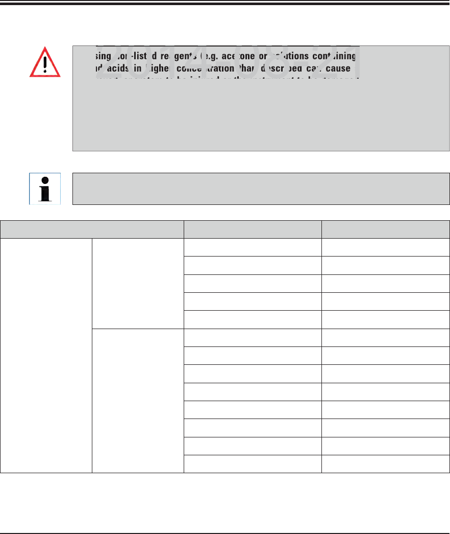
128 Instructions for Use V 0.5 RevC - 08/2014
Appendix 1
Using non-listed reagents (e.g. acetone or solutions containing phenol) or reagents
and acids in higher concentration than described can cause specimens to be de-
stroyed, operators to be injured or the instrument to be damaged. Use the instrument
in this way at your own risk. Leica Biosystems or affiliated sales and service organi-
zations shall not assume any warranty claims or liability.
Flammable reagents and solvents must not be heated for fire and explosion protec-
tion reasons. Keep away all ignition sources when handling flammable solvents and
reagents.
Staining method or reagent group Reagent name Notes
H&E kit Leica Infinity ST Hemalast
ST Hematoxylin
ST Differentiator
ST Bluing
ST Eosin
Leica SelecTech 560 Hematoxylin
560MX Hematoxylin
Define MX-aq
Blue Buffer-8
Y515 Alcoholic Eosin
Y515LT Alcoholic Eosin
515 Eosin Trichrome
Eosin Phloxine
A1 Compatible reagents
All Leica reagents for preinstalled Leica programs are tested with the instrument for
staining quality and compatibility of materials.
DRAFT
DRAFT
DRAFT
2014 08 21
g non-listed reagents (e.g. acetone or solutions containing
nd acids in higher concentration than described can cause sp
ro ed operators to be inj red or the instr ment to be damaged
2014 08 21
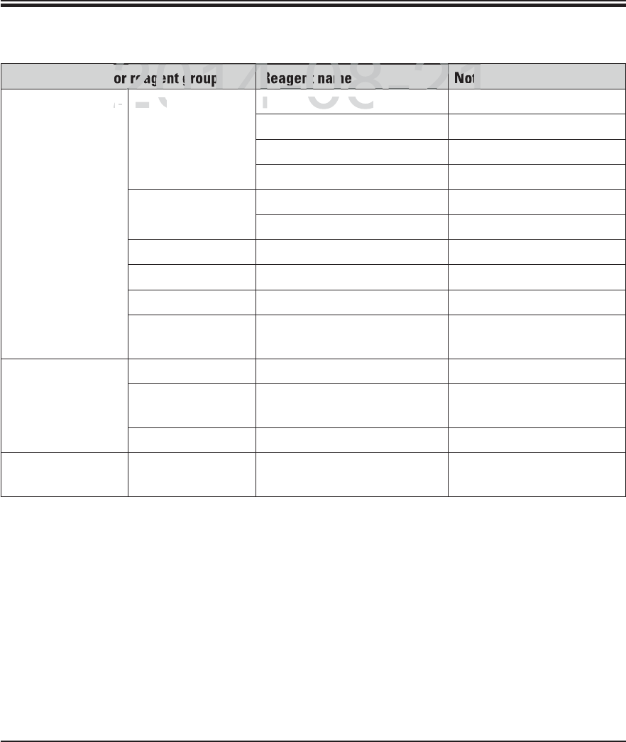
129
Leica HistoCore SPECTRA ST
Appendix 1
Staining method or reagent group Reagent name Notes
Other H&E re-
agents
Leica Gill II Hematoxylin
Gill III Hematoxylin
Harris Hematoxylin
Mayer's Hemalaun
Leica Alcoholic Eosin
Aqueous Eosin (1 %)
Leica Scott's Tap Water Solution
Leica Acid Alcohol 0.5 %
Leica Acid Alcohol 1.0 %
Customer/User-
defined
Hydrochloric Acid 2 %
PAS Leica Periodic Acid 0.5 %
Customer/User-
defined
Periodic Acid (up to 10 %)
Leica Schiff's Reagent
Diastase-PAS Leica Diastase-Solution (37 °C) Use in heated reagent
cuvette: 37 °C
A1 Compatible reagents (continued)
DRAFT
DRAFT
DRAFT
2014-08-21
2
2014
4082
21
2
2014
2
4-08-2
4
21
2
reagent group
Reagent name
Note
ee
-
-
L
e
i
c
aLeica
G
ill II Hematox
y
lin
Gill II Hematoxylin
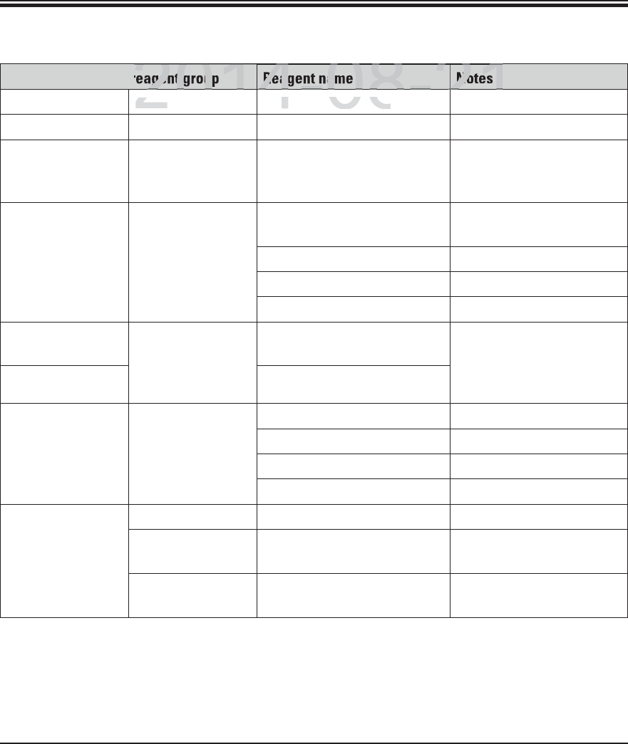
130 Instructions for Use V 0.5 RevC - 08/2014
Appendix 1
A1 Compatible reagents (continued)
Staining method or reagent group Reagent name Notes
Alcian Blue-PAS Leica Alcian Blue-Solution
Alcian Blue Leica
Alcian Blue and
other Staining
Methods
Leica Nuclear fast Red
Gomori Trichrome
Blue and Green
Collagen Staining
Leica Weigert Hematoxylin
(A+B Solution)
Gomori Trichrome Blue Stain
1 % Acetic Acid
Light Green
Perl's Iron
Staining
Leica Potassium-Ferrocyanide
Solution
Must not come into con-
tact with metal ions
Only for use with coated
5 series rack clips
Hydrochloride Acid Solution
Giemsa Leica Methanol Solution A
Stain 1 Solution B
Stain 2 Solution C
Buffer Solution D
Congo Red
Amyloid Stain
Leica Congo Red Solution
Leica 1 % Potassium Hydroxide
Solution
Customer/User-
defined
Saturated Lithium Carbonate
Solution
DRAFT
DRAFT
DRAFT
2014-08-21
201
4082
21
2
201
4-08-2
21
2
agent grou
Reagent na
Notes
L
e
i
c
aLeica
Alcian Blue-
S
olutio
ncian Blue-Solution
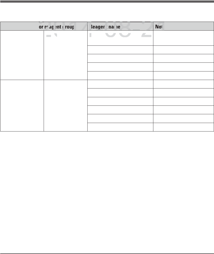
131
Leica HistoCore SPECTRA ST
Appendix 1
A1 Compatible reagents (continued)
Staining method or reagent group Reagent name Notes
Alcian Yellow
for Helicobacter
Pylori
Leica Alcian Yellow-Solution
(0.25 %Alcian Yellow)
5 % Periodic Acid
5 % Sodium Metabisulfite
6.8 pH Sorensen Buffer
Toluidin Blue Solution
Elastic Stain/Ver-
hoeff's van Gieson
Leica 5 % Alcoholic Hematoxylin
10 % Ferric Chloride
Lugol's Iodin Solution
2 % Ferric Chloride
Verhoeff's Staining Solution
Van Gieson's Stain
DRAFT
DRAFT
DRAFT
2014-08-21
2
2014
4082
21
2
2014
2
4-08-2
4
21
2
reagent group
Reagent name
Note
L
e
i
c
aLeica
Alcian Yellow-
S
olution
Alcian Yellow-Solution
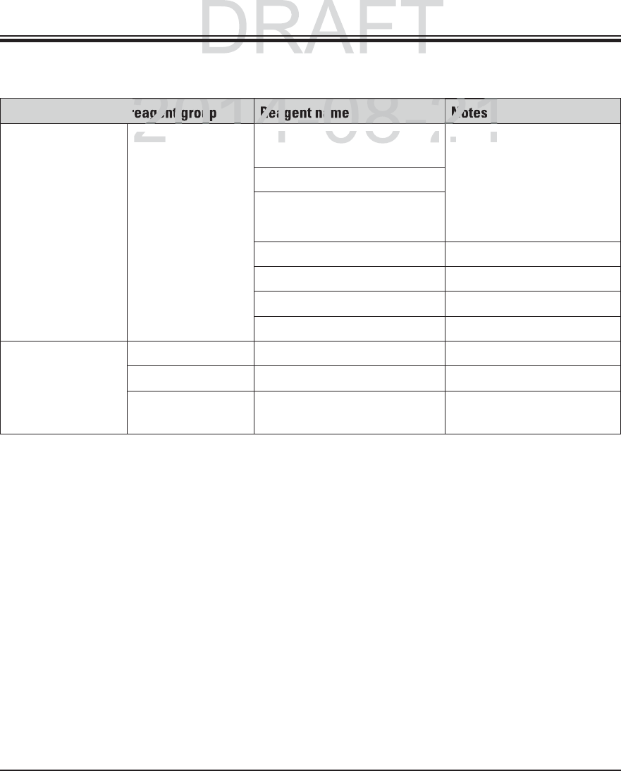
132 Instructions for Use V 0.5 RevC - 08/2014
Appendix 1
A1 Compatible reagents (continued)
Staining method or reagent group Reagent name Notes
Gomori Methena-
mine Silver Stain
Leica Modified Chromic Acid (up
to 5 %)
Use in heated reagent
cuvette: 55 °C
Must not come into con-
tact with metal ions
Only for use with coated
5 series rack clips
Methenamine Borax
0.5 % Silver Nitrate
1 % Sodium Bisulfate
1 % Gold Chloride
2 % Sodium Thiosulfate
Light Green
Papanicolaou
(PAP)
Leica EA-50
Leica Orange G-6
Leica EA-65 (Secondary Counter
Stain)
DRAFT
DRAFT
2014-08-21
201
4082
21
201
4-08-2
21
2
agent grou
Reagent na
Notes
L
e
i
c
aLeica
Modified Chromic Acid
(
u
podified Chromic Acid (up
U
se
e
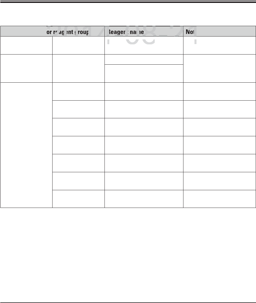
133
Leica HistoCore SPECTRA ST
Appendix 1
A1 Compatible reagents (continued)
Staining method or reagent group Reagent name Notes
Schmorl's
Reduction
Schmorl's Solution Only for use with coated
5 series rack clips
(Müller) Colloidal
Iron
Colloidal Iron Solution Only for use with coated
5 series rack clips
Ferrocyanide-Hydrochloric
Acid Solution
Other reagents Customer/User-
defined
Anilin Blue
Customer/User-
defined
Methylene Blue
Customer/User-
defined
Fast Green
Customer/User-
defined
Carmin
Customer/User-
defined
Southgate or Mayer's Mici-
carmine
Customer/User-
defined
Neutral Red
Customer/User-
defined
Safranin
DRAFT
DRAFT
DRAFT
2014-08-21
2
2014
4082
21
2
2014
2
4-08-2
4
21
2
reagent group
Reagent name
Note
S
chmorl's
S
olution
Schmorl's Solution
OO
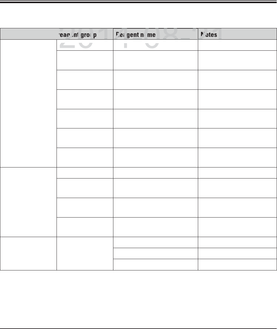
134 Instructions for Use V 0.5 RevC - 08/2014
Appendix 1
A1 Compatible reagents (continued)
Staining method or reagent group Reagent name Notes
Solvent Leica/Customer Xylene, Toluene
Leica Leica ST Ultra Xylene Substitute based on
Alipahtic Hydrocarbons
Leica Leica Clearene Limonene based Xylene
Substitute
Merck Merck Neo-Clear Xylene Substitute based on
Alipahtic Hydrocarbons
Carl Roth Roti®-Histol Limonene based Xylene
Substitute
Richard-Allen Sci./
Thermo Sci.
Clear-Rite 3 Xylene Substitute based on
Alipahtic Hydrocarbons
Richard-Allen Sci./
Thermo Sci.
Citrus Clearing Solvent Limonene based Xylene
Substitute
Alcohol Leica/Customer 2-Propanol (Isopropanol)
Leica/Customer Ethanol
Methanol
Richard-Allen Sci./
Thermo Sci.
Dehydrant Ethyl Alcohol, Methyl Al-
cohol
Richard-Allen Sci./
Thermo Sci.
Flex Isopropyl, Alcohol, Methyl
Alcohol
Usual Acids (Max.
Concentration)
Customer/User-
defined
Acetic Acid (up to 15 %)
Hydrochloric Acid (up to 5 %)
Picric Acid (up to 3 %)
DRAFT
DRAFT
DRAFT
2014-08-21
201
4082
21
2
201
4-08-2
21
2
agent grou
Reagent na
Notes
Leica
/C
ustome
rLeica/Custom
Xyl
ene
,
T
o
l
uene
ene, Toluene
DRAFT
201
4-
08
-
21

www.LeicaBiosystems.com
Leica Biosystems Nussloch GmbH
Heidelberger Strasse 17–19
D- 69226 Nussloch
Phone: +49 - (0) 6224 - 143 0
Fax: +49 - (0) 6224 - 143 268
Web: www.LeicaBiosystems.com
DRAFT
ms com
ms com
201
4-
08
-
21