Leica Biosystems Nussloch SPECTRAST Multistainer User Manual DRAFT 14051280101J SPECTRA ST IFU 1v3J en
Leica Biosystems Nussloch GmbH Multistainer DRAFT 14051280101J SPECTRA ST IFU 1v3J en
Contents
- 1. User Manual
- 2. 14051280101J_SPECTRA_ST_IFU_1v3J_en.pdf
- 3. HistoCore_SPECTRA_ST_RFID-Registration_1v1B_Multi.pdf
14051280101J_SPECTRA_ST_IFU_1v3J_en.pdf
HistoCore SPECTRA ST
Stainer
The Pathology Company
Instructions for Use
English
Order No. 14 0512 80101 - Revision J
Always keep this manual with the instrument.
Read carefully before working with the instrument.
Version 1.3, Revision J - 01.2017

3
HistoCore SPECTRA ST
The information, numerical data, notes and value judgments contained in this manual represent the
current state of scientific knowledge and state-of-the-art technology as we understand it following
thorough investigation in this field.
We are under no obligation to update the present manual periodically and on an ongoing basis
according to the latest technical developments, nor to provide our customers with additional copies,
updates etc. of this manual.
To the extent permitted in accordance with the national legal system as applicable in each individual
case, we shall not be held liable for erroneous statements, drawings, technical illustrations etc.
contained in this manual. In particular, no liability whatsoever is accepted for any financial loss or
consequential damage caused by or related to compliance with statements or other information in this
manual.
Statements, drawings, illustrations and other information regarding the contents or technical details of
the present Instructions for Use are not to be considered warranted characteristics of our products.
These are determined only by the contract provisions agreed between ourselves and our customers.
Leica reserves the right to change technical specifications as well as manufacturing processes without
prior notice. Only in this way is it possible to continuously improve the technology and manufacturing
techniques used in our products.
This document is protected under copyright laws. All copyrights to this documentation are held by Leica
Biosystems Nussloch GmbH.
Any reproduction of text and illustrations (or of any parts thereof) by means of print, photocopy,
microfiche, web cam or other methods – including any electronic systems and media – requires express
prior permission in writing by Leica Biosystems Nussloch GmbH.
For the instrument serial number and year of manufacture, please refer to the nameplate on the back of
the instrument.
Note
Leica Biosystems Nussloch GmbH
Heidelberger Str. 17 - 19
D-69226 Nussloch, Germany
Germany
Phone: +49 - (0) 6224 - 143 0
Fax: +49 - (0) 6224 - 143 268
Web: www.LeicaBiosystems.com

4Version 1.3, Revision J
Table of Contents
1. Important Information ................................................................................................................................ 8
1.1 Symbols and their meanings.......................................................................................................................... 8
1.2 Instrument type .............................................................................................................................................. 12
1.3 User Group ...................................................................................................................................................... 12
1.4 Intended use ................................................................................................................................................... 12
1.5 Copyright - Instrument software ................................................................................................................. 13
2. Security ....................................................................................................................................................... 14
2.1 Safety Notes ................................................................................................................................................... 14
2.2 Warnings ......................................................................................................................................................... 15
2.3 Safety features on the instrument .............................................................................................................. 18
3. Instrument Components and Specifications ........................................................................................ 19
3.1 Standard delivery ........................................................................................................................................... 19
3.2 Specifications ................................................................................................................................................. 20
3.3 General overview - front view ..................................................................................................................... 22
3.4 General overview - rear view ...................................................................................................................... 23
3.5 General overview - inside view ................................................................................................................... 24
4. Installation and Starting up .................................................................................................................... 25
4.1 Installation site requirements ...................................................................................................................... 25
4.2 Rinsing water connection ............................................................................................................................ 25
4.2.1 Joint connection of all 6 rinsing water stations ....................................................................................... 26
4.2.2 Combined connection 4+2 rinsing water stations .................................................................................... 27
4.2.3 Wastewater connection ............................................................................................................................... 29
4.3 Electrical connection .................................................................................................................................... 29
4.3.1 Using an external uninterruptible power supply (UPS) ........................................................................... 30
4.4 Exhaust air connection ................................................................................................................................. 31
4.5 Switching the instrument on and off .......................................................................................................... 31
5. Operation .................................................................................................................................................... 33
5.1 User interface - overview ............................................................................................................................. 33
5.2 Elements of the status display ..................................................................................................................... 34
5.3 Process status display .................................................................................................................................. 35
5.4 Displaying the drawers ................................................................................................................................. 37
5.5 Main menu - overview .................................................................................................................................. 38
5.5.1 The keyboard .................................................................................................................................................. 39
5.6 User settings ................................................................................................................................................... 40
5.7 Basic settings ................................................................................................................................................. 42
5.7.1 Language settings ......................................................................................................................................... 43
5.7.2 Regional settings ........................................................................................................................................... 44
5.7.3 Date and time ................................................................................................................................................. 45
5.7.4 Alarm and signal tones ................................................................................................................................. 45

5
HistoCore SPECTRA ST
Table of Contents
5.7.5 Oven settings .................................................................................................................................................. 47
5.7.6 Movement speed - up/down movement (agitation) ................................................................................. 48
5.7.7 Data management ......................................................................................................................................... 49
5.7.8 Service access ............................................................................................................................................... 53
5.7.9 Event viewer ................................................................................................................................................... 53
5.7.10 Network settings ............................................................................................................................................ 55
5.8 Reagent list ..................................................................................................................................................... 56
5.8.1 Defining heated reagent (optional) ............................................................................................................. 57
5.8.2 Copying a reagent .......................................................................................................................................... 59
5.8.3 Changing the RMS data for a reagent........................................................................................................ 60
5.8.4 Process classes ............................................................................................................................................. 60
5.9 Staining programs ......................................................................................................................................... 63
5.9.1 Assigning a rack handle color to a staining program.............................................................................. 64
5.9.2 Leica staining programs (preinstalled) ...................................................................................................... 66
5.9.3 Adapting the Leica H&E staining program ................................................................................................ 67
5.9.4 User-defined staining programs ................................................................................................................. 68
5.9.5 Creating or copying a new staining program............................................................................................ 69
5.9.6 Inserting or copying a new program step ................................................................................................. 71
5.9.7 Re-sorting program steps............................................................................................................................. 72
5.9.8 Prioritizing programs for creating the bathlayout .................................................................................... 74
5.9.9 Creating the bathlayout ................................................................................................................................ 75
5.9.10 Filling reagents after bathlayout creation ................................................................................................. 76
5.9.11 Adapting a bathlayout ................................................................................................................................... 82
6. Daily instrument setup ............................................................................................................................. 85
6.1 Preparing the instrument for daily setup ................................................................................................... 85
6.2 Daily instrument setup .................................................................................................................................. 86
6.2.1 Preparation and handling of reagent vessels ........................................................................................... 86
6.2.2 Automatic fill level scan ............................................................................................................................... 88
6.3 Reagent management system (RMS) ......................................................................................................... 89
6.4 Station details ................................................................................................................................................. 90
6.5 Preparing the rack ......................................................................................................................................... 96
6.6 The staining process ..................................................................................................................................... 99
6.6.1 Starting the staining process..................................................................................................................... 100
6.6.2 Monitoring the staining process ............................................................................................................... 102
6.6.3 Staining process completed ...................................................................................................................... 102
6.6.4 Canceling the staining program ................................................................................................................ 104
6.6.5 Operation as a workstation ........................................................................................................................ 106

6Version 1.3, Revision J
Table of Contents
6.6.6 Finishing the daily operation ...................................................................................................................... 106
7. Cleaning and Maintenance ...................................................................................................................108
7.1 Important notes about cleaning this instrument .................................................................................... 108
7.2 Exterior surfaces, varnished surfaces, instrument hood ...................................................................... 108
7.3 TFT touchscreen .......................................................................................................................................... 108
7.4 Interior and drain pan ................................................................................................................................. 108
7.5 Transport arms ............................................................................................................................................. 109
7.6 Specimen slide reader station................................................................................................................... 109
7.7 Input and output drawers ........................................................................................................................... 109
7.8 Dry transfer station ...................................................................................................................................... 110
7.9 Transfer station (optional) .......................................................................................................................... 111
7.10 Reagent vessels, rinsing water vessels and (optional) heated vessels ............................................. 111
7.11 Rack and handle .......................................................................................................................................... 112
7.12 Water drainage ............................................................................................................................................ 113
7.13 Water drain hose ......................................................................................................................................... 114
7.14 Replacing the filter cartridge of the water intake filter ......................................................................... 114
7.15 Changing the active carbon filter.............................................................................................................. 115
7.16 Cleaning the ovens ...................................................................................................................................... 116
7.17 Oven air filter ................................................................................................................................................ 118
7.18 Maintenance and cleaning intervals........................................................................................................ 118
7.18.1 Daily cleaning and maintenance............................................................................................................... 119
7.18.2 Cleaning and maintenance as necessary ............................................................................................... 119
7.18.3 Weekly cleaning and maintenance .......................................................................................................... 119
7.18.4 Monthly maintenance and cleaning ......................................................................................................... 120
7.18.5 Cleaning and Maintenance Every Three Months .................................................................................. 120
7.18.6 Annual maintenance and cleaning ........................................................................................................... 120
8. Malfunctions and Troubleshooting .....................................................................................................121
8.1 Fault remedies for instrument malfunctions ........................................................................................... 121
8.2 Power failure scenario and instrument malfunction ............................................................................. 123
8.2.1 Procedure after a power failure................................................................................................................ 126
8.2.2 Resuming the staining process after a power failure ........................................................................... 127
8.2.3 Canceling all staining processes after a power failure ........................................................................ 129
8.2.4 Detaching a rack from the gripper mechanism ...................................................................................... 130
8.3 Replacing main fuses .................................................................................................................................. 132
8.4 Remote Care ................................................................................................................................................. 132
8.5 Water drain system blocked ...................................................................................................................... 133

7
HistoCore SPECTRA ST
Table of Contents
9. Instrument Components and Specifications ......................................................................................135
9.1 Optional instrument components .............................................................................................................. 135
9.2 Optional accessories .................................................................................................................................. 135
10. Warranty and Service ............................................................................................................................141
11. Decommissioning and disposal ........................................................................................................... 142
12. Decontamination Confirmation ............................................................................................................143
Appendix 1 - Compatible reagents ................................................................................................................. 144
8Version 1.3, Revision J
Important Information
1
1. Important Information
1.1 Symbols and their meanings
Caution
Leica Biosystems GmbH assumes no liability for consequential loss or damage due to failure to
observe the following instructions, particularly in relation to transportation and package handling,
and failure to observe the instructions for handling the instrument carefully.
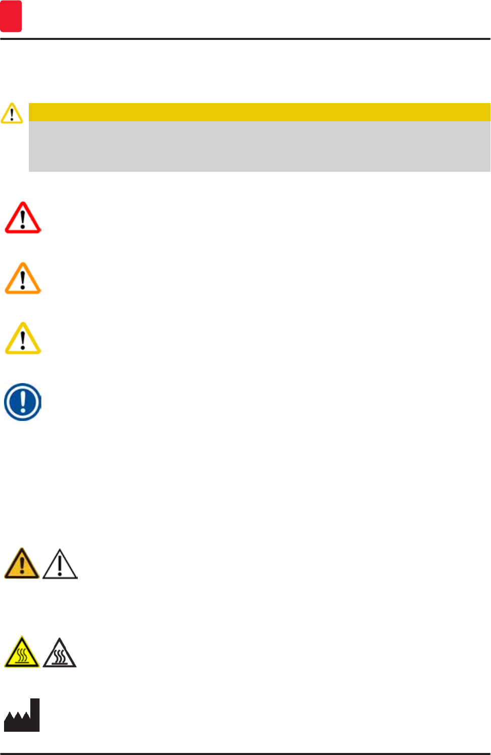
Symbol: Title of the symbol: Danger
Description: Indicates an imminently hazardous situation which, if
not avoided, will result in death or serious injuries.
Symbol: Title of the symbol: Warning
Description: Indicates a potentially hazardous situation which, if
not avoided, may result in death or serious injury.
Symbol: Title of the symbol: Caution
Description: Indicates a potentially hazardous situation which, if
not avoided, may result in death or serious injury.
Symbol: Title of the symbol: Note
Description: Indicates a situation with the potential for property
damage which, if not avoided, may result in damage
to the machine or something in its vicinity.
Symbol: Title of the symbol: Item number
→ "Fig. 7 - 1"Description: Item numbers for numbering illustrations. Numbers in
red refer to item numbers in illustrations.
Symbol: Title of the symbol: Function key
Save Description: Software symbols that have to be pressed on the
input screen are displayed as bold, gray text.
Symbol: Title of the symbol: Caution
Description: Indicates the need for the user to consult the
Instructions for Use for important cautionary
information such as warnings and precautions that
cannot, for a variety of reasons, be presented on the
medical device itself.
Symbol: Title of the symbol: Warning, hot surface
Description: Instrument surfaces which become hot during
operation are marked with this symbol. Avoid direct
contact to prevent risk of burning.
Symbol: Title of the symbol: Manufacturer
Description: Indicates the manufacturer of the medical product.
9
HistoCore SPECTRA ST
Important Information 1
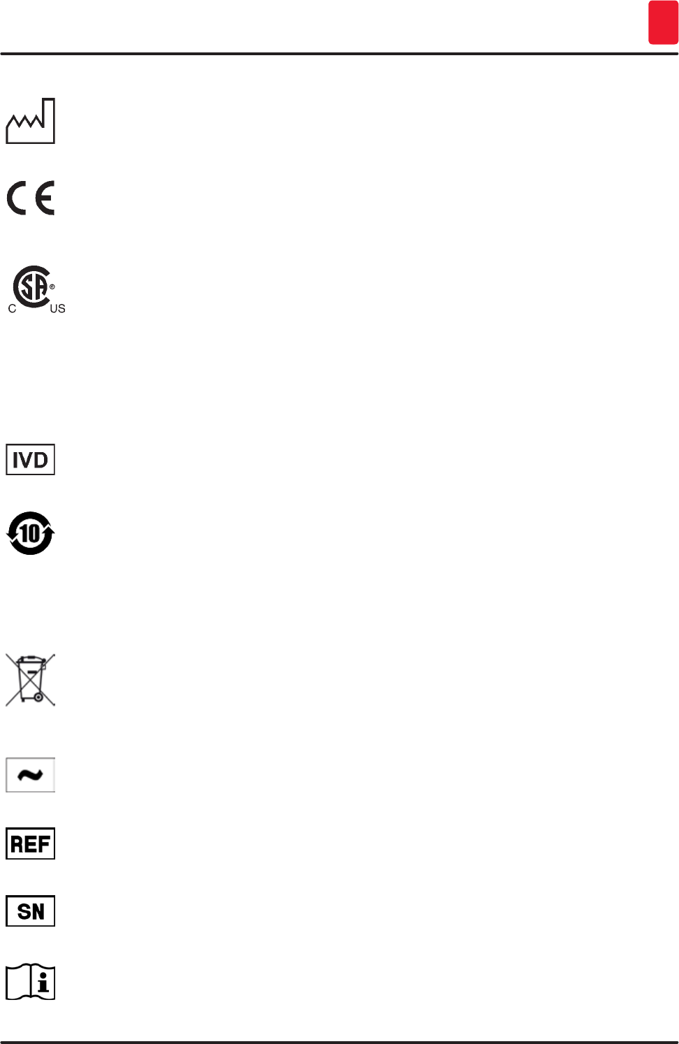
Symbol: Title of the symbol: Manufacturing date
Description: Indicates the date when the medical device was
manufactured.
Symbol: Title of the symbol: CE Compliance
Description: The CE marking is the manufacturer's declaration
that the medical product meets the requirements of
the applicable EC directives.
Symbol: Title of the symbol: CSA Statement (Canada/USA)
Description: The CSA test mark means that a product has been
tested and fulfills the applicable safety standards:
CAN/CSA-C22.2 NO. 61010-1-04;
CAN/CSA-C22.2 NO. 61010-2-010-04;
CAN/CSA-C22.2 NO. 61010-2-101-04
Product is listed under Master Contract
Number: 217333
Symbol: Title of the symbol: In vitro diagnostic medical device
Description: Indicates a medical device that is intended to be
used as an in vitro diagnostic medical device.
Symbol: Title of the symbol: China ROHS
Description: Environmental protection symbol of the China RoHS
directive. The number in the symbol indicates the
"Environment-friendly Use Period" of the product in
years. The symbol is used if a substance restricted
in China is used in excess of the maximum permitted
limit.
Symbol: Title of the symbol: WEEE Symbol
Description: The WEEE symbol, indicating separate collection
for WEEE - Waste of electrical and electronic
equipment, consists of the crossed-out wheeled bin
(§ 7 ElektroG).
Symbol: Title of the symbol: Alternating current
Symbol: Title of the symbol: Article number
Description: Indicates the manufacturer's catalog number so that
the medical device can be identified.
Symbol: Title of the symbol: Serial number
Description: Indicates the manufacturer's serial number so that a
specific medical device can be identified.
Symbol: Title of the symbol: Consult Instructions for Use
Description: Indicates the need for the user to consult the
Instructions for Use.
10 Version 1.3, Revision J
Important Information
1
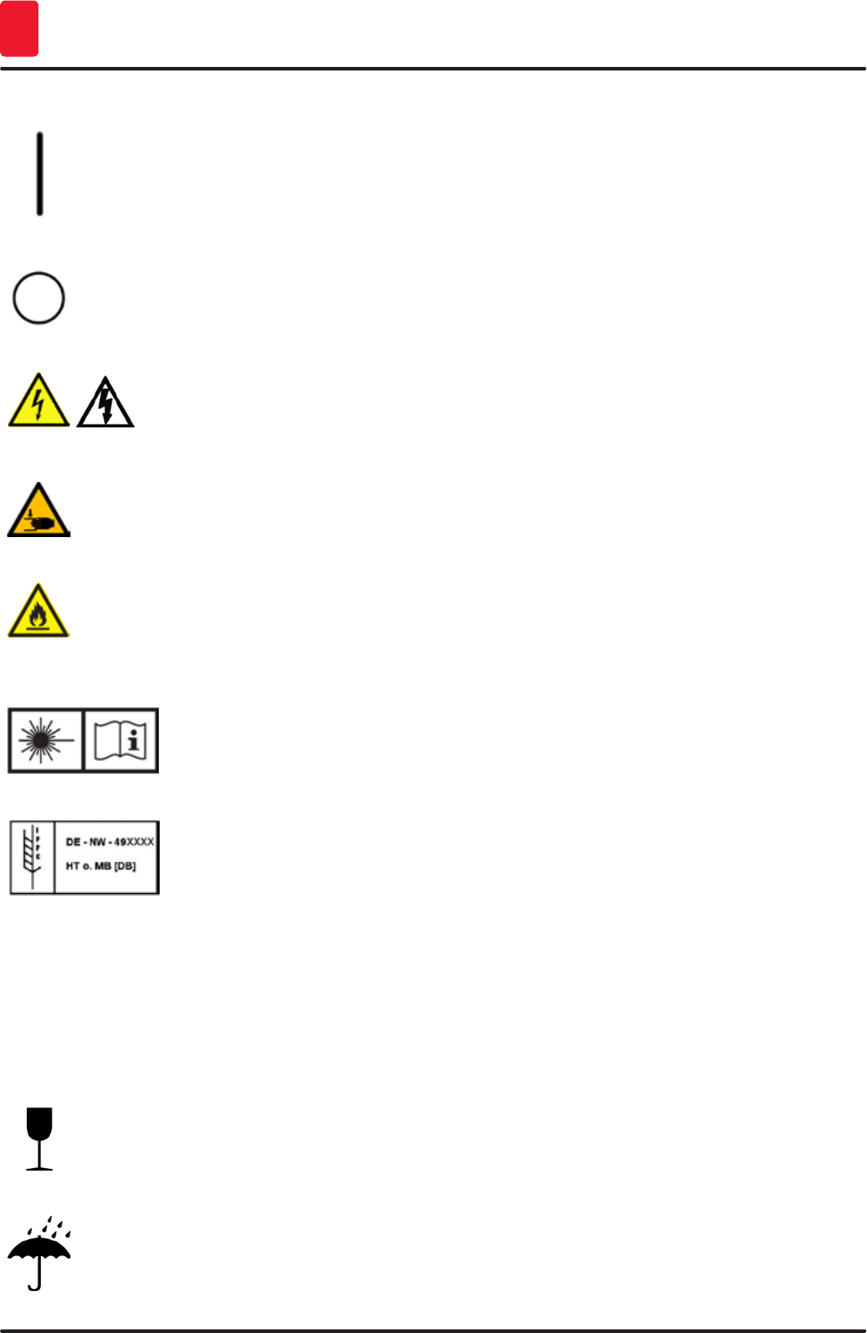
Symbol: Title of the symbol: ON (Power)
Description: The power supply is connected upon pushing the
power switch.
Symbol: Title of the symbol: OFF (Power)
Description: The power supply is disconnected upon pushing the
power switch.
Symbol: Title of the symbol: Warning, risk of electric shock
Description: Instrument surfaces or areas which become
energized during operation are marked with this
symbol. Therefore, direct contact is to be avoided.
Symbol: Title of the symbol: Caution: danger of crushing
Symbol: Title of the symbol: Flammable
Description: Flammable reagents, solvents and cleaning agents
are labeled with this symbol.
Symbol: Title of the symbol: Observe the laser beam warning and Instructions for
Use
Description: The product uses a class 1 laser source. The safety
notes for handling lasers and the Instructions for Use
must be observed!
Symbol: Title of the symbol: IPPC symbol
Description: The IPPC symbol includes
IPPC symbol
• Country code to ISO 3166, e.g. DE for Germany
• Regional identifier, e.g. NW for North
Rhine-Westphalia
• Registration number, unique number beginning
with 49.
• Treatment method, e.g. HT (heat treatment)
Symbol: Title of the symbol: Fragile, handle with care
Description: Indicates a medical device that can be broken or
damaged if not handled carefully.
Symbol: Title of the symbol: Store dry
Description: Indicates a medical device that needs to be
protected from moisture.
11
HistoCore SPECTRA ST
Important Information 1
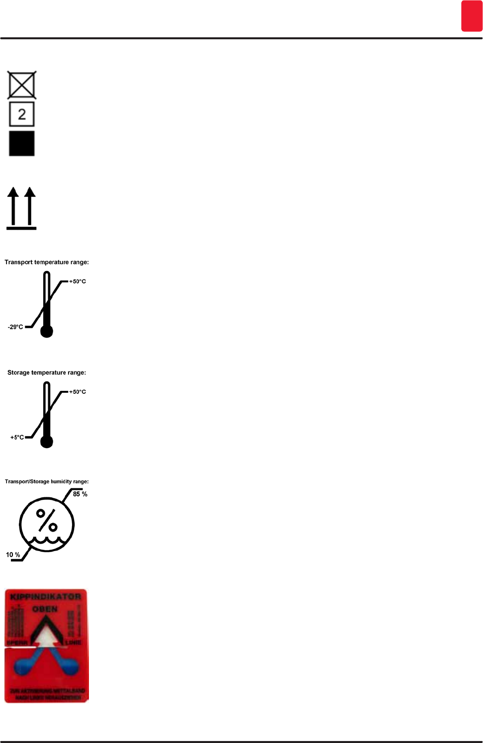
Symbol: Title of the symbol: Stack limit
Description: The largest number of identical packages allowed to
be stacked; "2" stands for the number of permitted
packages.
Symbol: Title of the symbol: This way up
Description: Indicates correct upright position of the transport
package.
Symbol: Title of the symbol: Temperature limit for transport
Description: Indicates the temperature limits for transport to
which the medical device can be safely exposed.
Symbol: Title of the symbol: Temperature limit for storage
Description: Indicates the temperature limits for storage to which
the medical device can be safely exposed.
Symbol: Title of the symbol: Humidity limitation for transport and storage
Description: Indicates the range of humidity for transport and
storage to which the medical device can be safely
exposed.
Appearance: Indication: Tilt indicator
Description: Indicator to monitor whether the shipment has been
transported and stored in upright position according
to your requirements. With a pitch of 60° or more,
the blue quartz sand flows into the arrow-shaped
indicator window and sticks there permanently.
Improper handling of the shipment is immediately
detectable and can be proven definitively.
12 Version 1.3, Revision J
Important Information
1
Note
Upon delivery of the instrument, the recipient must check that the tilt indicator is intact. The
responsible Leica representative must be notified in the case that all indicators have been
triggered.
Note
The Instructions for Use are accompanied by a bound "RFID Registration" brochure. The brochure
contains country-specific information for the operator about the meaning of the RFID symbols and
registration numbers available on the packaging or the HistoCore SPECTRA ST nameplate.
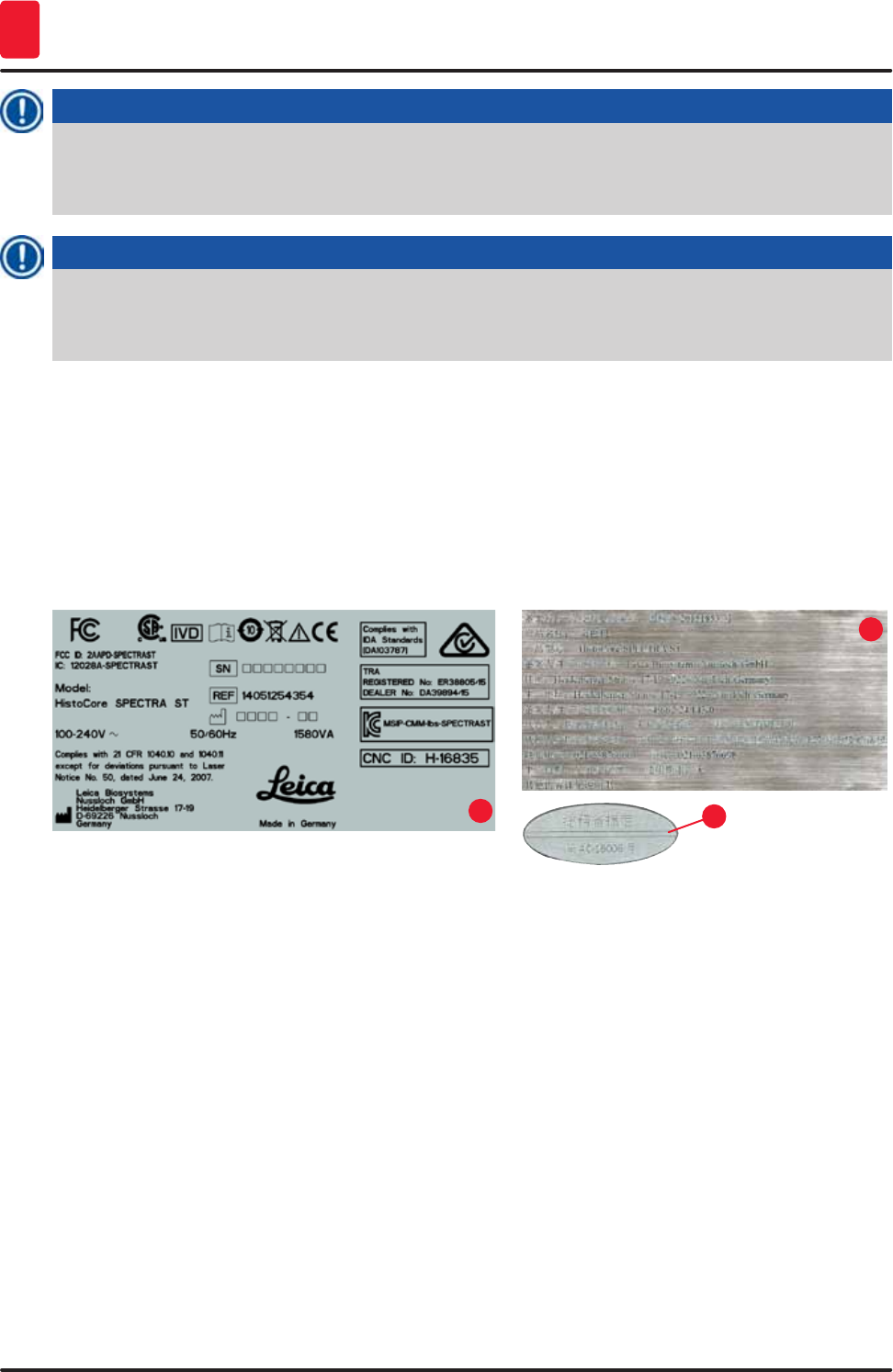
1.2 Instrument type
All information provided in these Instructions for Use applies only to the instrument type indicated on
the title page. A nameplate (→ "Fig. 1-1") indicating the instrument serial number is attached to the rear
side of the instrument. Furthermore, a plate with Chinese (→ "Fig. 1-2") and Japanese (→ "Fig. 1-3")
registration information is located on the rear panel of the instrument. The figure below (→ "Fig. 1-1") is
provided as an example only and shows a valid nameplate for this instrument.
Fig. 1
13
2
1.3 User Group
• The HistoCore SPECTRA ST must only be operated by authorized personnel comprehensively trained
in using lab reagents and their application in histology.
• All laboratory personnel designated to operate this instrument must read these Instructions for Use
carefully and must be familiar with all technical features of the instrument before attempting to
operate it.
1.4 Intended use
The HistoCore SPECTRA ST is an in-vitro diagnostics instrument. The HistoCore SPECTRA ST is a stainer
for laboratory applications and intended for the preparation of histological and cytological specimens.

13
HistoCore SPECTRA ST
Important Information 1
Danger
Any use of the instrument that deviates from the designated use is considered improper. Failure to
adhere to these instructions may result in an accident, personal injury, damage to the instrument
or accessory equipment. Proper and intended use includes compliance with all inspection
and maintenance instructions, along with the observance of all instructions in the Instructions
for Use as well as the constant inspection of the reagents for storage life and quality. The
HistoCore SPECTRA ST carries out the specified staining steps automatically. The manufacturer
assumes no liability for the staining results in the case that the staining steps and programs are
entered incorrectly. Thus, the end user is independently responsible for self-created reagents or
program entries.
1.5 Copyright - Instrument software
The software installed and used on the HistoCore SPECTRA ST is subject to the following license
agreements:
1. GNU General Public License Version 2.0, 3.0
2. GNU Lesser General Public License 2.1
3. additional software not licensed under the GPL/LGPL
The complete license agreements for the first and second can be found on the provided language CD
(link to Standard Delivery) in the "Software Licenses" directory.
Leica Biosystems provides a complete machine-readable copy of the source code to every third party
in compliance with the agreements of the GPL/LGPL applicable for the source code or of the other
applicable licenses. To contact us, go to www.leicabiosystems.com and use the corresponding contact
form.

14 Version 1.3, Revision J
Security
2
2. Security
2.1 Safety Notes
Caution
• The safety and caution notes in this chapter must be observed at all times. Be sure to read these
notes even if you are already familiar with the operation and use of other Leica products.
• The protective devices located on the instrument and the accessories must not be removed or
modified.
• Only qualified service personnel authorized by Leica may repair the instrument and access its
internal components.
Residual risks:
• The instrument has been designed and constructed with the latest state-of-the-art technology
and according to recognized standards and regulations with regard to safety technology.
Operating or handling the instrument incorrectly can place the user or other personnel at risk of
injury or death or can cause damage to the instrument or property.
• The instrument may be used only as intended and only if all of its safety features are in proper
working condition.
• If malfunctions occur that can impede safety, the instrument must be put out of operation
immediately and the responsible Leica service technician must be notified.
• Only original spare parts and permitted original Leica accessories may be used.
• Electromagnetic compatibility, emitted interference and immunity to interference are applicable,
as are the requirements in accordance with IEC 61326-2-6. The requirements in accordance
with IEC 61010-1, IEC 61010-2-101, IEC 62366 and ISO 14971 with regard to safety information are
applicable.
These Instructions for Use include important instructions and information related to the operating safety
and maintenance of the instrument.
The Instructions for Use are an important part of the product, and must be read carefully prior to startup
and use and must always be kept near the instrument.
Note
These Instructions for Use must be appropriately supplemented as required by the existing
regulations on accident prevention and environmental safety in the operator‘s country.
The instrument's EC Declaration of Conformity can be found on the Internet at:
http://www.LeicaBiosystems.com
This instrument has been built and tested in accordance with the safety requirements for electrical
equipment for measurement, control, and laboratory use. To maintain this condition and ensure safe
operation, the user must observe all notes and warnings contained in these Instructions for Use.
15
HistoCore SPECTRA ST
Security 2
Warning
• The presence of malware on the system can lead to uncontrolled system behavior. Ensuring that
the behavior of the instrument conforms to specifications is no longer possible in this case! If the
user suspects malware is on the system, the local IT department must be notified immediately.
• You must make sure that any data loaded onto the instrument is free of viruses. No anti-virus
software is provided.
• The instrument is only suited for integration in a firewall-protected network. Leica shall not
assume any liability for errors due to integration in an unprotected network.
• ONLY technicians trained and permitted by Leica can connect a USB input device (mouse/
keyboard, etc.). This also applies to the network connection, which is to be used only together
with Remote Care (service diagnostics).
In the interest of specimen safety, the HistoCore SPECTRA ST indicates when it is necessary
for the user to intervene using on-screen messages and audible signals. Therefore, the
HistoCore SPECTRA ST stainer requires that the user is within hearing distance during operation.
Danger
The product uses a class 1 laser source.
Caution, laser radiation! Do not look into the beam! This can cause injury to the retina of the eye.
Danger
LASER RADIATION - DO NOT
STARE INTO BEAM
ISO 60825-1: 2014
P<1 mW, λ = 630 to 670 nm
Pulse duration = 500 μs
Class 1 laser product
2.2 Warnings
The safety devices installed in this instrument by the manufacturer only constitute the basis for accident
prevention. Operating the instrument safely is, above all, the responsibility of the owner, as well as the
designated personnel who operate, service or repair the instrument.
To ensure trouble-free operation of the instrument, make sure to comply with the following instructions
and warnings.
Please note that electrostatic discharges can result due to direct or indirect contact with the
HistoCore SPECTRA ST.
Danger
Markings on the instrument surface showing the warning triangle indicate that the correct
operating instructions (as defined in these Instructions for Use) must be followed when operating
or replacing the item marked. Failure to adhere to these instructions may lead to accidents causing
personal injury and/or damage to the instrument or accessories or destroyed, unusable specimens.
16 Version 1.3, Revision J
Security
2
Danger
Certain surfaces of the instrument are hot during operation under normal conditions. They are
marked with this warning sign. Touching these surfaces without suitable safety measures can
cause burns.
Warnings - Transport and installation
Caution
• The instrument must only be transported in an upright position.
• The empty weight of the instrument is 185 kg; therefore, four qualified persons are required to lift
or carry the instrument!
• Use non-skid gloves to lift the device!
• Leica recommends commissioning a transport company to transport, install or (where
applicable) relocate the instrument.
• Retain the instrument packaging.
• Place the instrument on a sturdy laboratory bench (load capacity 150 kg/m2) and adjust it to a
horizontal position.
• Prevent the instrument from being exposed to direct sunlight.
• Only connect the instrument to a grounded power socket. Do not interfere with the grounding
function by using an extension cord without a ground wire.
• Exposure to extreme temperature changes between storage and installation locations and high
air humidity may cause condensation inside the instrument. If this is the case, wait at least two
hours before switching on the instrument.
• The instrument must only be installed at the area of use with and under direction of Leica-
trained staff. This also applies to the potential transport to a new area of use. We recommend
using personnel trained by Leica to recommission the instrument.
• In accordance with national rules and regulations, the operator may be obligated to provide
long-term protection of the public water supply from contamination due to backflowing water
from the building installation. In Europe, the protection device of the potable water installation
to be connected is selected in accordance with the specifications of DIN EN 1717:2011-08
(information status August 2013).
Warnings – Handling reagents
Caution
• Take care when handling solvents!
• Always wear protective clothing suitable for laboratory use, as well as rubber gloves and safety
goggles when handling the chemicals used in this instrument.
• The installation site must be well-ventilated. Alternatively, the instrument can be
connected to an external exhaust air extraction system. The chemicals to be used in the
HistoCore SPECTRA ST are flammable and hazardous to health.
• Do not operate the instrument in rooms with an explosion hazard.
• When disposing of spent reagents, observe the applicable local regulations and the waste
disposal regulations of the company/institution in which the instrument is being operated.
• Reagent vessels must always be filled outside of the instrument in compliance with the safety
information.
17
HistoCore SPECTRA ST
Security 2
Warnings – Operating the instrument
Caution
• The instrument may be operated by trained laboratory personnel only. It must only be operated
for the purpose of its designated use and according to the instructions contained in these
Instructions for Use. Antistatic protective clothing made from natural fibers (e.g. cotton) should
be worn when working with the instrument.
• When working with the instrument, wear suitable protective clothing (lab coat and gloves) for
protection from reagents and potentially infectious micro-biological contaminations.
• In the event of an emergency, switch off the power switch and unplug the instrument from the
power supply (circuit breaker in accordance with EN ISO 61010-1).
• For severe instrument faults, the warning and error messages on the screen must be followed.
Samples located in the process must be removed from the instrument immediately. The user is
responsible for the safe further processing of the samples.
• There is a fire hazard if work with an exposed flame (e.g. Bunsen burner) is carried out in the
direct vicinity of the instrument (solvent vapors). Therefore, keep all ignition sources at least
2 meters away from the instrument!
• Be absolutely certain to operate the instrument with the active carbon filter, technical
ventilation system and an exhaust air hose because use of the instrument may lead to the
formation of solvent vapors that are both hazardous to health and flammable, even when the
instrument is used according to its intended use!
Note
For instrument fume control, Leica recommends a delivery volume of 50 m3/h and an 8x air exchange
rate (25 m3/m2/h) in the lab.
Caution
• Personal protective clothing in the form of a respirator must be worn when working directly with
reagent vessels that contain solvents.
• Opening the hood when one or more staining program(s) are active causes delays in the
respective processing steps since no transport movements take place for this time frame. This
can result in changes to the staining quality.
• Make sure to keep the hood closed if the staining programs are active. Leica assumes no
liability for loss of quality for staining programs caused by opening the hood during the staining
process.
• CAUTION when closing the hood: Crushing hazard! Do not reach into the swivel range of the
hood!
• Liquid must not get behind covers or in gaps while operating or cleaning the instrument. This
also applies to the transport arms.
• CAUTION for programs that start with an oven step! In this case, the input station from which
the specimen slides are removed with the transport arm must NOT be filled with a flammable
reagent (e.g. xylene, xylene substitute or alcohols). The oven temperature can be up to 70 °C. This
can result in the reagent igniting and can cause damage to the instrument and specimens.
• The water supply has to be shut off during pauses in use of the instrument and when the
instrument is turned off.
18 Version 1.3, Revision J
Security
2
Warnings - Cleaning and Maintenance
Caution
• Before any maintenance, switch off the instrument and unplug it from its power supply.
• When cleaning the instrument, wear suitable protective clothing (lab coat and gloves) to protect
from reagents and potentially infectious micro-biological contaminations.
• When using cleaners, please comply with the safety instructions of the manufacturer and the
laboratory safety regulations.
• Do not use any of the following for cleaning the outside surfaces of the instrument: alcohol,
detergents containing alcohol (glass cleaners), abrasive cleaning powders, solvents containing
acetone, ammonia, chlorine, or xylene!
• Clean the hoods and housing using mild commercial, pH-neutral household cleaners. The
finished surfaces are not resistant to solvents and xylene substitutes!
• The plastic reagent vessels of the rinsing water and reagent stations can be cleaned in a
dishwasher at a maximum temperature of +65 °C. Any standard cleaning agent for laboratory
dishwashers may be used. Never clean the plastic reagent vessels at higher temperatures since
higher temperatures can cause the reagent vessels to become deformed.
2.3 Safety features on the instrument
As soon as the hood of the instrument is opened, the movements of the transport arms are stopped in a
horizontal plane (x and y-axis) for safety reasons to eliminate danger to the user and specimen damage
due to collision with moving parts.
Caution
• Make sure to keep the hood closed if the staining programs are active. Leica assumes no
liability for loss of quality for staining programs caused by opening the hood during the staining
process.
• Opening the hood when one or more staining program(s) is/are active causes delays in the
respective processing steps since no transport movements take place for this time frame. This
can result in changes to the staining quality.

19
HistoCore SPECTRA ST
Instrument Components and Specifications 3
3. Instrument Components and Specifications
3.1 Standard delivery
Qty Designation Order No.
1 HistoCore SPECTRA ST Basic instrument 14 0512 54354
1 Reagent vessel set consisting of:
46 reagent vessels with covers
6 blue rinsing water vessels
6 O-rings 7x2
14 0512 47507
1 Set of label covers for the input and output drawers consisting of:
10 pc. blank
5 pc. "H2O"=Water
5 pc. "A"=Alcohol
5 pc. "S"=Solvent, e.g. xylene)
14 0512 55161
1 Active carbon filter set (2 pcs.) 14 0512 53772
1 Outlet hose, 2 m 14 0512 55279
1 Tubing band clamp 30 45/12 DIN 3017 RF 14 0422 31972
1 Water supply kit consisting of: 14 0512 49324
2 Inflow hoses, 10 mm, 2.5 m 14 0474 32325
1 Extension hose, 1.5 m 14 0512 49334
1 Y-piece G3/4 14 3000 00351
2 G3/4 - G3/8 double nipple 14 3000 00350
1 Filter housing 14 0512 49331
1 Filter cartridge 14 0512 49332
1 Bushing G3/4 14 3000 00360
1 Blind cap G3/4 14 3000 00434
1 Gasket 14 0512 54772
1 Single-head wrench SW30 DIN894 14 0330 54755
1 Exhaust hose, 2 m 14 0512 54365
2 Tubing band clamp 30 45/12 DIN 3017 RF 14 0422 31972
1 5.5 x 150 screwdriver 14 0170 10702
2 T16 A fuse 14 6000 04696
1 Molykote 111 grease, 100 g 14 0336 35460
3 Rack for 30 specimen slides; 3 pcs. per package 14 0512 52473
1 Handle for rack for 30 specimen slides; yellow, 3 pcs. per package 14 0512 52476
1 Handle for rack for 30 specimen slides; dark blue, 3 pcs. per
package
14 0512 52478
1 Handle for rack for 30 specimen slides; red, 3 pcs. per package 14 0512 52480
1 Handle for rack for 30 specimen slides; white, 3 pcs. per package 14 0512 52484

20 Version 1.3, Revision J
Instrument Components and Specifications
3
Qty Designation Order No.
1 Instructions for Use, printed (German/English, with Language
CD 14 0512 80200)
14 0512 80001
The country specific power cord needs to be ordered separately- Please find a list of all power cords
available for your device on our website www.LeicaBiosystems.com within the product section.
Note
The delivered components must be carefully compared against the packing list, delivery note, and
your order. Should you find any discrepancies, please contact your Leica sales office without delay.
3.2 Specifications
Nominal supply voltages: 100-240 V AC +10 %
Nominal frequency: 50/60 Hz
Power draw: 1580 VA
Fuses: 2 x T16 A H 250 V AC
IEC 1010 classification: Protection class 1
Pollution degree 2
Overvoltage category: II
Fresh water connection:
Hose material: PVC
Hose length: 2500 mm
Connecting piece: G3/8
Inner diameter: 10 mm
Outer diameter: 16 mm
Internal pressure: Maximum/maximum: 2 bar/6 bar
Required flow rate: Min. 1.7 L/minute
Required water quality: Type 1, ISO 3696
Waste water connection:
Hose length: 2000 mm/4000 mm
Inner diameter: 32 mm
Outer diameter: 36.8 mm
Exhaust air:
Hose length: 2000 mm
Inner diameter: 50 mm
Outer diameter: 60 mm
Exhaust performance: 27.3 m3/h
Exhaust extraction: Active carbon filter and exhaust hose for
connecting with an external exhaust system
Heat emission: 1580 J/s

21
HistoCore SPECTRA ST
Instrument Components and Specifications 3
A-weighted noise level: < 70 dB (A)
International protection class: IP20
Connections: 1 x RJ45 Ethernet (rear): RJ45 - LAN (external data management)
1 x RJ45 Ethernet (front): Only for service purposes
2 x USB 2.0: 5 V/500 mA (service & data storage)
Note
When using an external uninterruptible power supply (UPS), it should be designed for a capacity of
at least 1580 VA and secure operation over a time frame of at least 10 minutes.
Ambient conditions: 100-240 V AC +10 %
Operation: 50/60 Hz
Temperature: +18 °C to +30 °C
Relative humidity: 20 % to 80 %, non-condensing
Operating elevation: Up to a max. of 2000 m above sea level
Storage:
Temperature: +5 °C to +50 °C
Relative humidity: 10 % to 85 %, non-condensing
Transport:
Temperature: –29 °C to +50 °C
Relative humidity: 10 % to 85 %, non-condensing
Dimensions and weights:
Dimensions (Width x depth x height): Hood closed: 1354 x 785.5 x 587.5 mm
Hood open: 1354 x 785.5 x 943 mm
Empty weight (without reagents and
accessories)
185 kg
22 Version 1.3, Revision J
Instrument Components and Specifications
3
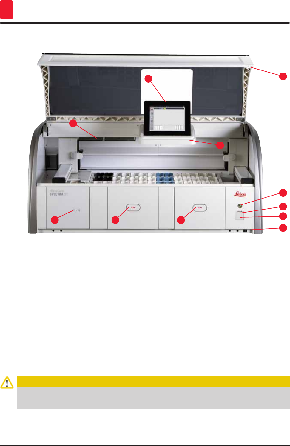
3.3 General overview - front view
Fig. 2
1
9
5
3
11
7
2
10
6
48
1 Insert for active carbon filter
2 Read-in area for Leica reagents
3 Input drawer (loader)
4 Output drawer (unloader)
5 Screen holder with internal illumination
6 Screen with user interface
7 USB ports (2 pcs.)
8 Service access
9On/off switch (power switch)
10 Lid
11 Operating switch
Caution
• The service access (→ "Fig. 2-8") may only be used by Leica certified service technicians!
• The read-in area cover (→ "Fig. 2-2") may only be removed by Leica certified service technicians.
23
HistoCore SPECTRA ST
Instrument Components and Specifications 3
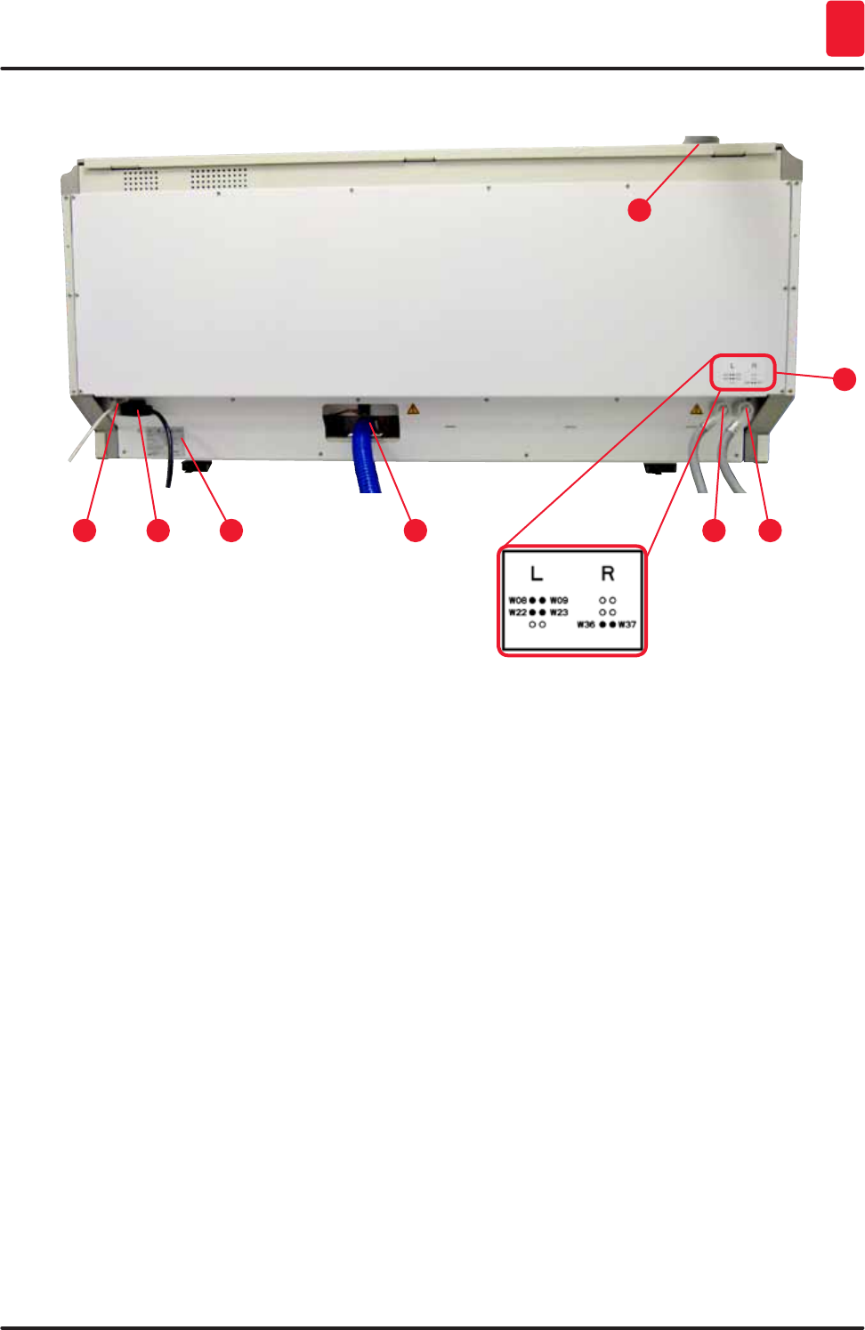
3.4 General overview - rear view
Fig. 3
153
7
2 64
8
1 Network connection (Remote Care)
2 Power supply
3 Nameplate
4 Wastewater connection
5 Rinsing water connection (group of 4)
6 Distilled water or rinsing water connection (group of 2)
7 Exhaust air connection
8 Water connection diagram
24 Version 1.3, Revision J
Instrument Components and Specifications
3
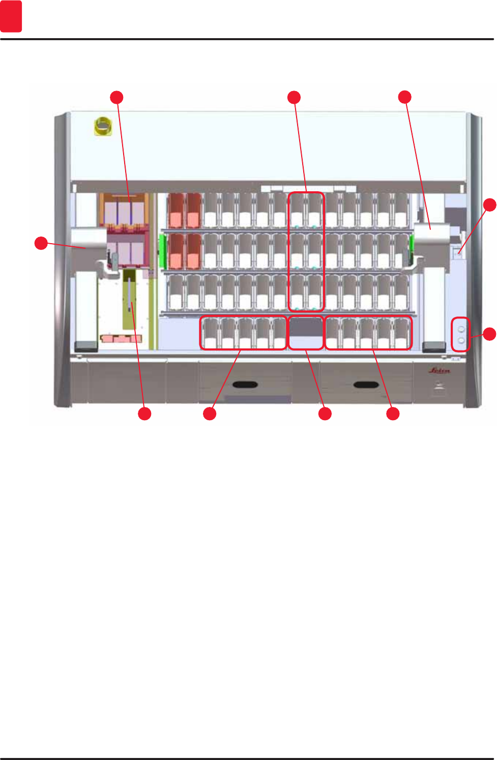
3.5 General overview - inside view
Fig. 4
1
5
3
7
2
6
4
8
10
11
1 Left transport arm
2 Specimen slide reader station
3 Loading stations, 5 pcs.
4 Dry transfer station, 2 pcs.
5 Unloading stations, 5 pcs.
6 Fuse holder, 2 pcs.
7 Right transport arm
8 Rinsing water stations, 6 pcs.
10 Drying oven stations, 6 pcs
11 Transfer station for HistoCore SPECTRA CV (optional)
25
HistoCore SPECTRA ST
Installation and Starting up 4
4. Installation and Starting up
4.1 Installation site requirements
Note
• Installation and leveling are carried out as part of the instrument installation by personnel
authorized by Leica only!
• Use 4 qualified persons when lifting the device; grab under the frame at all corners and lift
evenly.
• It must be ensured that there is a mostly vibration-free floor and sufficient clear space (approx.
1.10 m) above the laboratory bench to allow unobstructed opening of the hood.
• It is the user's responsibility to make sure that a compatible electromagnetic environment is
maintained so that the instrument can work as intended.
• Condensation water may form in the instrument if there is an extreme difference in temperature
between the storage location and the installation site and if air humidity is high at the same time. A
waiting time of at least two hours must be observed each time before switching on. Failure to comply
with this may cause damage to the instrument.
• Stable, exactly horizontal and level laboratory bench at least 1.40 m wide and 0.80 m deep.
• The counter area must be designed for handling loads of at least 150 kg/m2, vibration-free and level.
• Fume hood at a max. 2.0 m distance from the instrument.
• The instrument is suitable for operation in indoor areas only.
• The operating location must be well-ventilated and have an air exhaust.
• A rinsing water connection must be available at a maximum distance of 2.5 m. This connection must
also be easily accessible after installing the instrument.
• A waste water connection must be available at a maximum distance of 2 m. This connection must be
connected to the instrument with a constant outlet hose slope down and away from the instrument.
Caution
• A connection to an external exhaust system, a technical room ventilation system and an
integrated exhaust system with an active carbon filter reduce the concentration of solvent vapor
in the room air. The active carbon filters must be used for connecting to an external exhaust
system as well. Compliance with this is mandatory.
• The instrument operator bears responsibility for complying with workplace limits and the
measures necessary for this, including documentation.
• A grounded power supply socket must be available at a maximum distance of 3 m.
4.2 Rinsing water connection
Note
There is the option of choosing between two connection variants (→ p. 26 – 4.2.1 Joint connection
of all 6 rinsing water stations). The device must be programmed to the connection variant used (see
Chap. 6.4).
26 Version 1.3, Revision J
Installation and Starting up
4
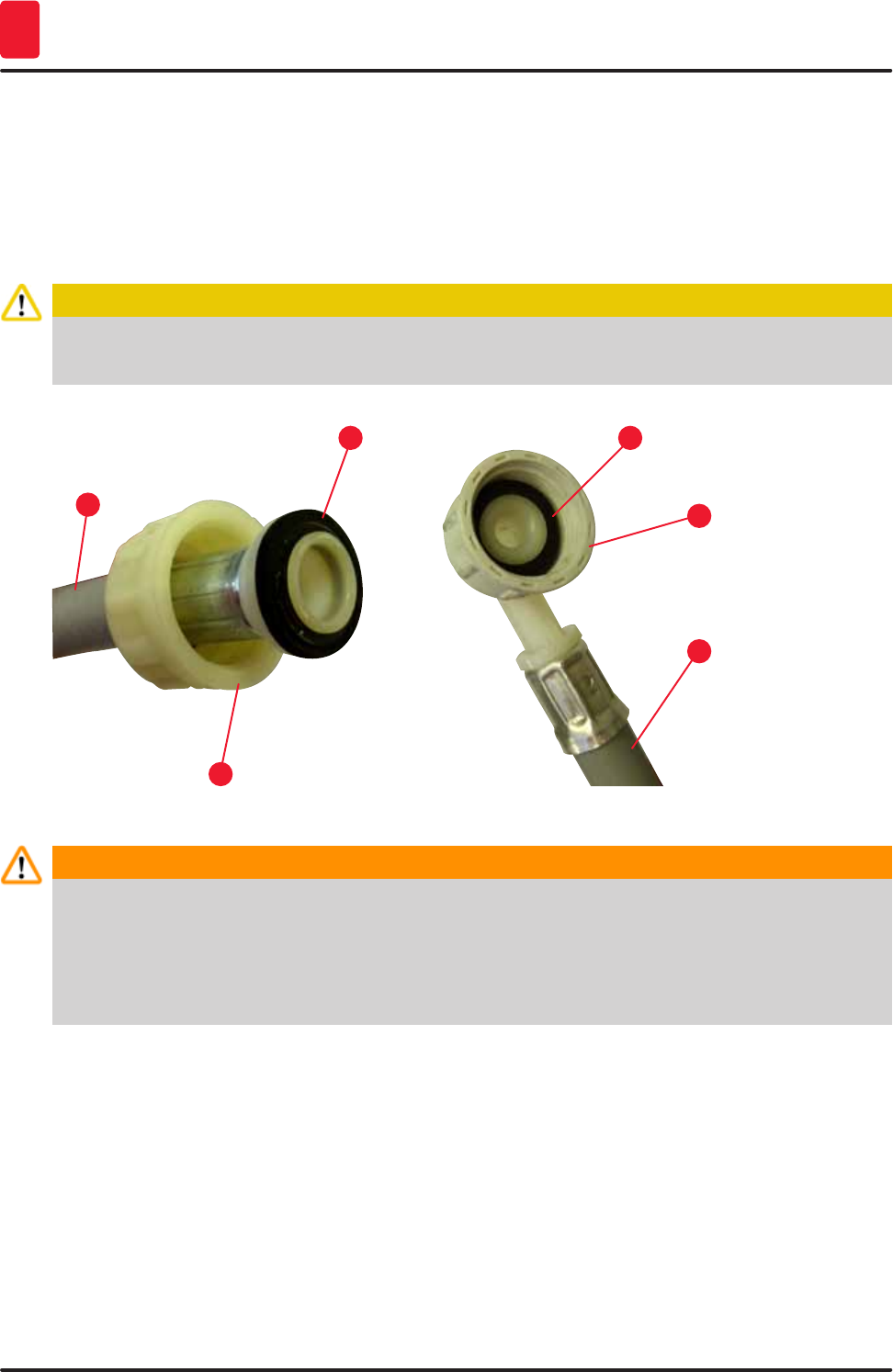
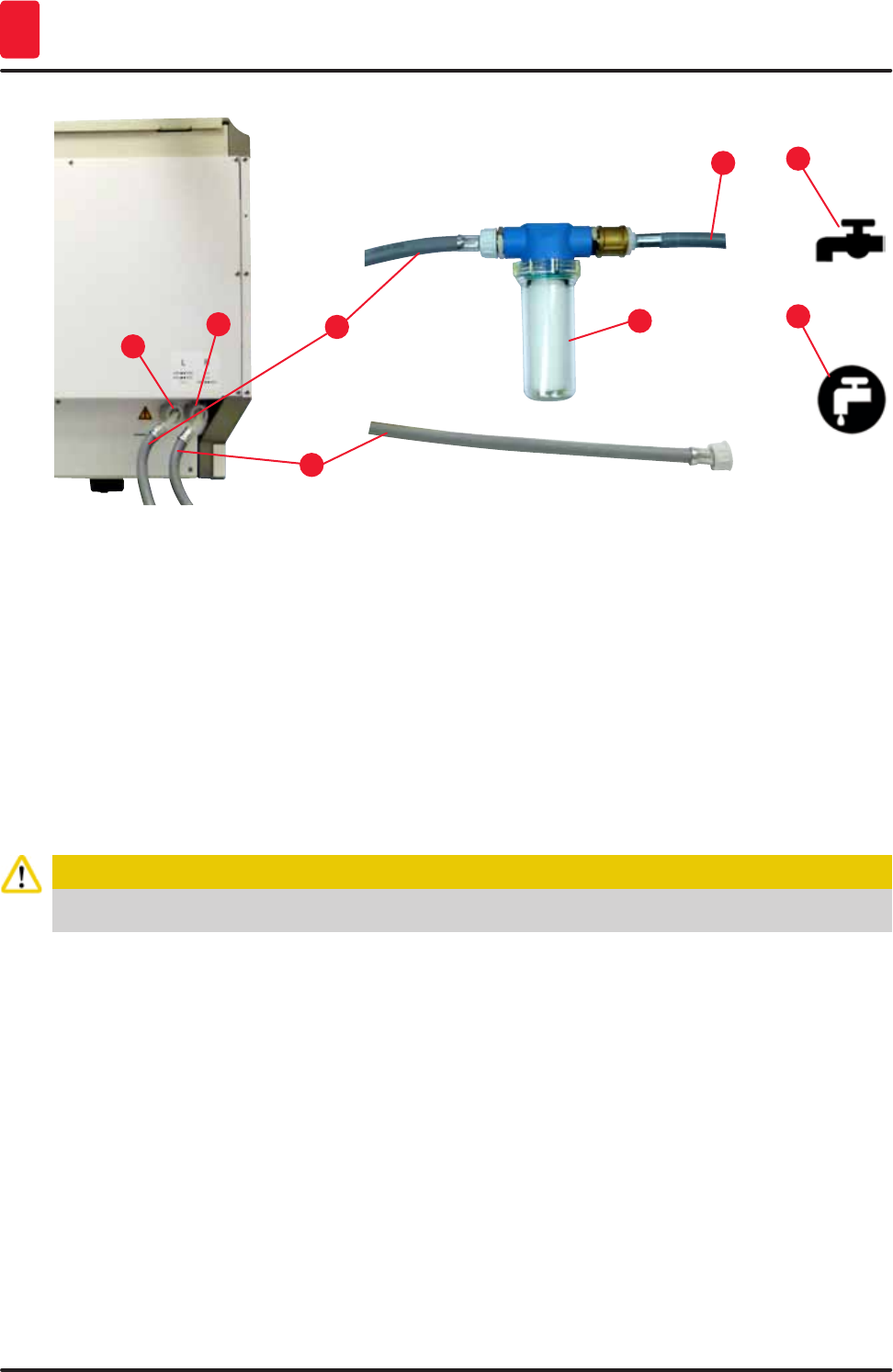
The following installation instructions apply for both types of connections:
• Take the rinsing water supply hose (→ "Fig. 5-1") out of the packaging.
• The connection for the water supply is straight (→ "Fig. 5-3"), the connection for the instrument side is
angled (→ "Fig. 5-4").
• Check whether the sealing rings (→ "Fig. 5-2") are attached to the connection for the water supply
(→ "Fig. 5-3") and to the connection for the instrument side (→ "Fig. 5-4").
Caution
The hose cannot be connected if the sealing rings are missing! In this case, contact the responsible
Leica service organization.
Fig. 5
1
3
2
4
1
2
Warning
Regardless of the selected connection variant (6 rinsing water stations or 4 rinsing water stations
and 2 deionized/demineralized water stations), both supply hoses are always connected to the
instrument.
Shut off the water supply during pauses in use of the instrument and when the instrument is turned
off.
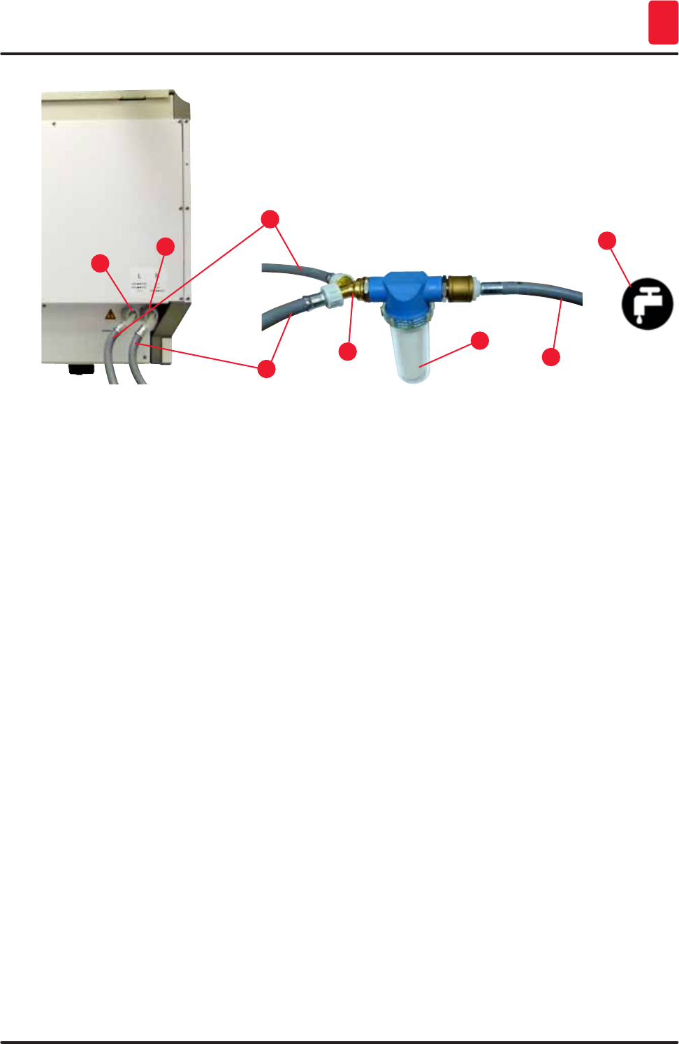
4.2.1 Joint connection of all 6 rinsing water stations
If all the rinsing water vessels (6 rinsing water stations) are to be connected to a shared rinsing water
connection, both supply hoses (→ "Fig. 6") are to be used in the manner shown. Both running water
connections are (→ "Fig. 6-4") connected to a single water tap (→ "Fig. 6-8") using a Y-piece:
27
HistoCore SPECTRA ST
Installation and Starting up 4
Fig. 6
1
5
3
7
2
6
4
8
1 Rinsing water supply hose 1 (2.5 m) Order No.: 14 0474 32325
2 Extension hose, 1.5 m Order No.: 14 0512 49334
3 Rinsing water supply hose 2 (2.5 m) Order No.: 14 0474 32325
4 Y piece Order No.: 14 3000 00351
5 Filter Order No.: 14 0512 49331
6 Rinsing water connection (group of 4)
7 Distilled water or rinsing water connection (group of 2)
8 Rinsing water connection in the lab
4.2.2 Combined connection 4+2 rinsing water stations
If the main connection (4 rinsing water stations) is to be connected to fresh water and the secondary
connection (2 rinsing water stations) is to be connected to a supply in the laboratory with distilled water
or desalinated water (demineralized water), proceed in accordance with the following connection
diagram:
28 Version 1.3, Revision J
Installation and Starting up
4
Fig. 7
1
5
3
7
2
648
1 Rinsing water supply hose 1 (2.5 m) Order No.: 14 0474 32325
2 Extension hose, 1.5 m Order No.: 14 0512 49334
3 Rinsing water supply hose 2 (2.5 m) Order No.: 14 0474 32325
4 Filter Order No.: 14 0512 49331
5 Rinsing water connection (group of 4)
6 Distilled water or rinsing water connection (group of 2)
7 Rinsing water connection in the lab
8 Distilled water/demineralized water connection in the
lab
Caution
It is imperative that you observe the correct supply hose connection (→ "Fig. 3-8")!
29
HistoCore SPECTRA ST
Installation and Starting up 4
4.2.3 Wastewater connection
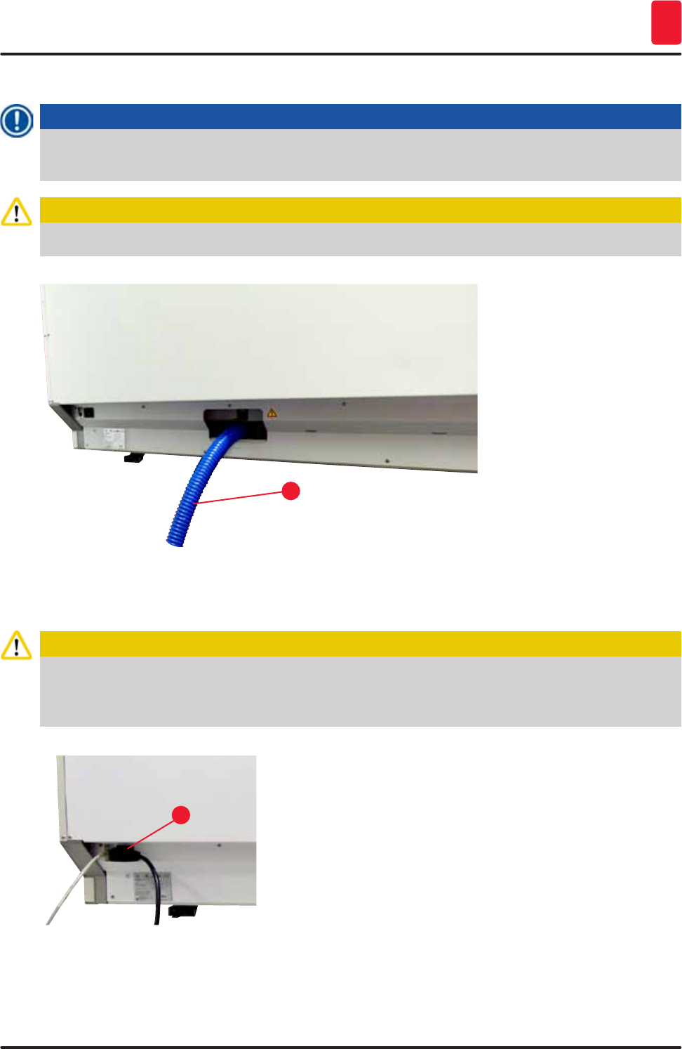
Note
The instrument has a passive wastewater outflow. The lab outflow siphon must therefore be located
at least 50 cm under the wastewater connection of the instrument.
Caution
The outlet hose (→ "Fig. 8-1") must be routed at a constant slope and must not be elevated.
Fig. 8
1
4.3 Electrical connection
Caution
• Use only the power cord provided, which is intended for the local power supply.
• Before connecting the instrument to the power supply, make sure that the main switch on the front
right side of the instrument is in the OFF ("0") position.
Fig. 9
1
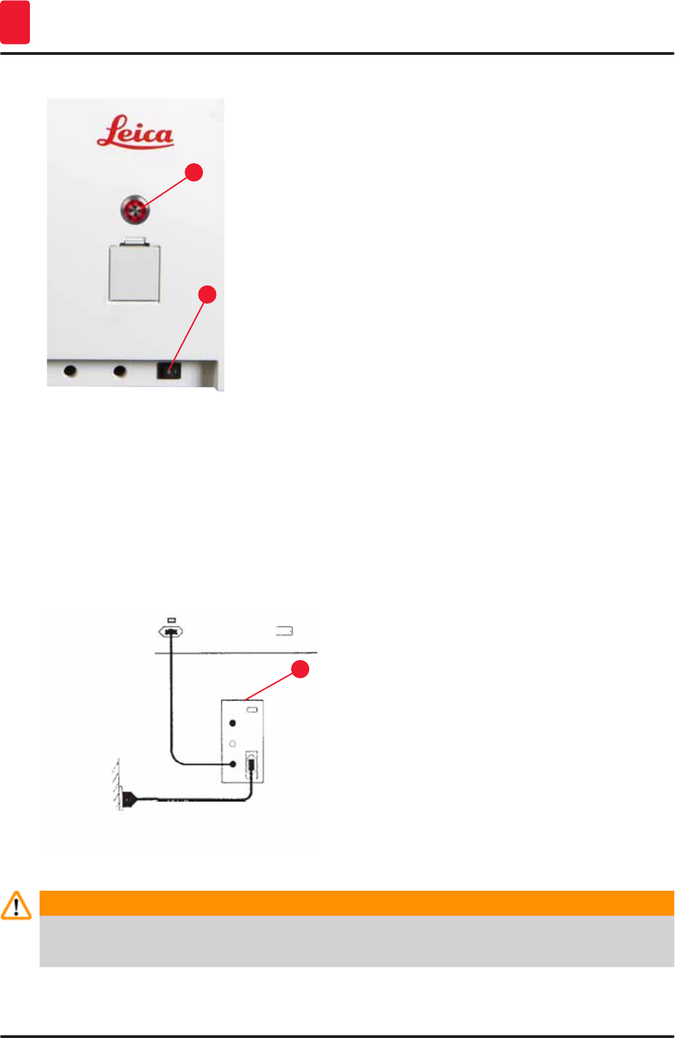
• Connect the power cord to the power input socket on the
rear panel of the instrument (→ "Fig. 9-1").
• Plug the power plug into a grounded power socket.
30 Version 1.3, Revision J
Installation and Starting up
4
Fig. 10
1
2
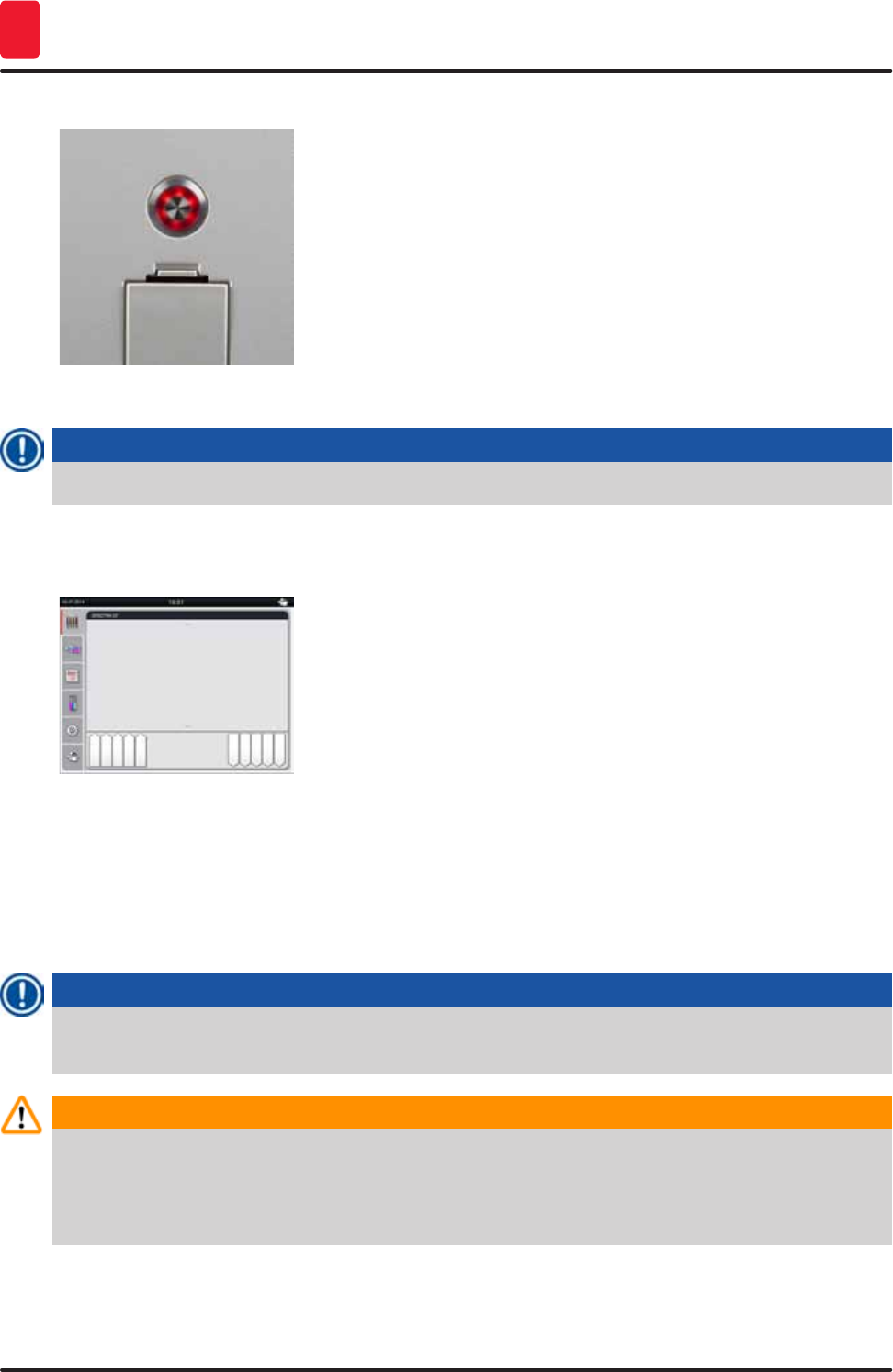
• Switch on the power switch (→ "Fig. 10-1").
• After a short period of time, the operating switch lights up
orange; once the software has completely started, it lights
up red (→ "Fig. 10-2") and the instrument is in standby mode.
• The operating switch can then be operated (→ p. 31 – 4.5
Switching the instrument on and off).
4.3.1 Using an external uninterruptible power supply (UPS)
An interruption of the staining process can be avoided in the event of a temporary power failure by
connecting a battery-buffered uninterruptible power supply (→ "Fig. 11-1") (UPS). The UPS should
enable an output of at least 1580 VA for the duration of 10 minutes. The UPS must be designed
for operating voltage at the installation location. The connection is carried out by connecting the
HistoCore SPECTRA ST power cord to the UPS power output socket. The UPS is connected to the power
socket in the lab.
Fig. 11
1
Warning
The UPS power cord must always remain in the power socket in the lab, even in the event of a
power outage. Otherwise grounding of the instrument cannot be ensured!
31
HistoCore SPECTRA ST
Installation and Starting up 4
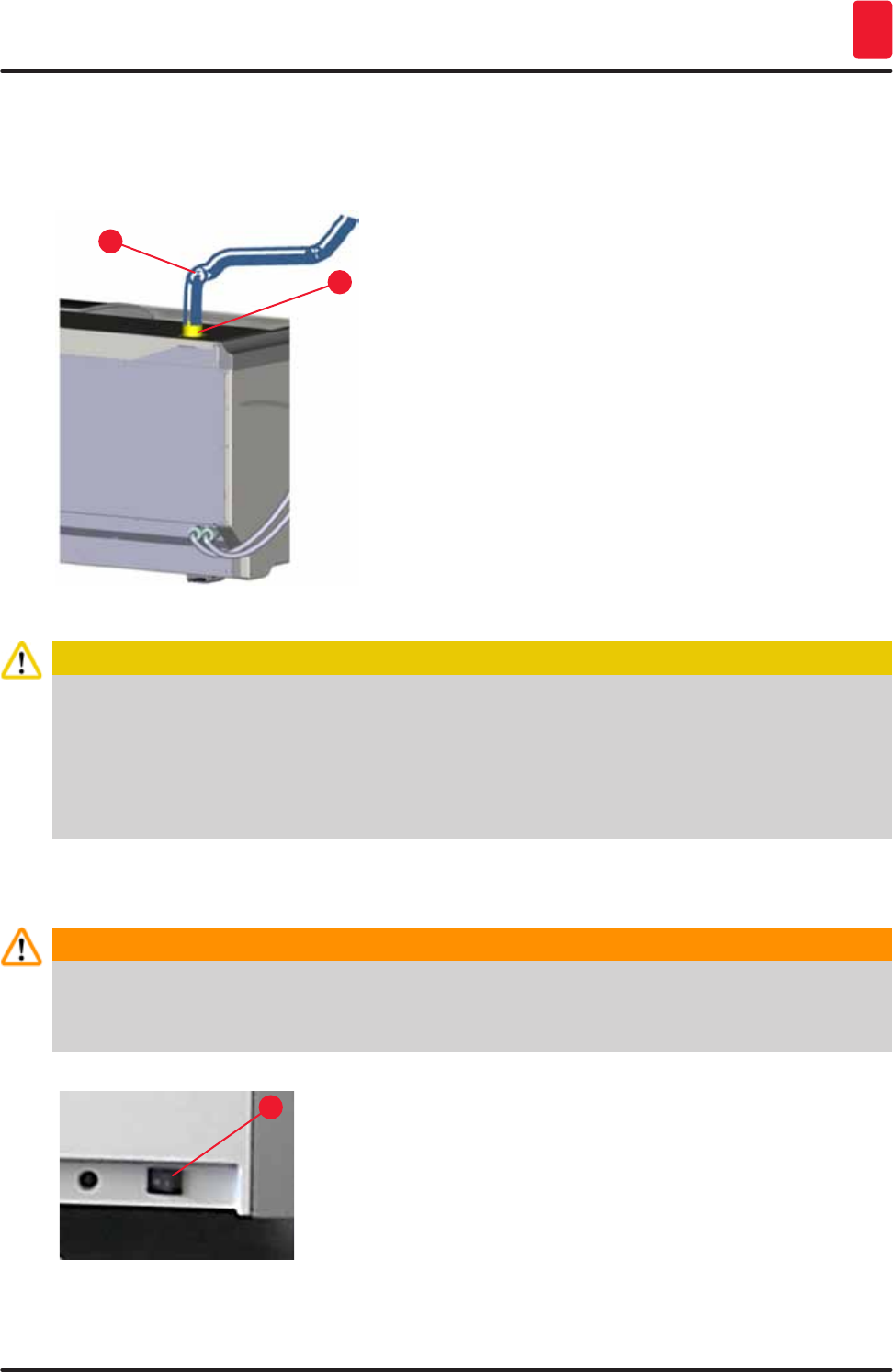
4.4 Exhaust air connection
» Connect one end of the exhaust air hose (→ "Fig. 12-1") to the exhaust port (→ "Fig. 12-2") on the
top side of the instrument. Connect the other end to an exhaust air device installed in the lab.
Fig. 12
1
2
Caution
• A connection to an external exhaust system and an integrated exhaust system with an active
carbon filter reduce the concentration of solvent in the room air and must be used. The vessels
must be covered when not using the instrument to prevent the unnecessary evaporation of the
reagents.
• The owner/operator must verify compliance with the workplace limit values when work is done
with hazardous materials.
4.5 Switching the instrument on and off
Warning
The instrument must be connected to a grounded power socket. For additional electrical fuse
protection, connecting the HistoCore SPECTRA ST to a socket with a residual current circuit
breaker (RCCB) is recommended.
Fig. 13
1
• Switch the power switch on the front right side at the bottom
of the instrument to ON ("I") (→ "Fig. 13-1").
32 Version 1.3, Revision J
Installation and Starting up
4
Fig. 14
• A few seconds after switching on the power switch, the
operating switch is illuminated in orange (→ "Fig. 14"). The
software's start process ends when the operating switch
illuminated in red.
Note
Pressing the operating switch in the orange phase does not start the instrument.
Fig. 15
• To start the instrument, press the red flashing operating
switch (→ "Fig. 14"); an acoustic signal sounds.
• During initialization, a verification of all stations ("fill level
scan") is carried out automatically.
• The operating switch is illuminated in green whenever the
instrument is ready to start.
• After completing the initialization phase, the "main menu"
(→ "Fig. 15") appears on the screen.
Switching off the instrument
• To switch the instrument into standby mode (e.g. overnight), press the operating switch (→ "Fig. 14")
twice. It then illuminates in red.
• For cleaning and maintenance, also switch off the instrument at the power switch (→ "Fig. 13-1").
Note
During the instrument setup or if no reagents have been added, non-filled stations are identified and
highlighted on the screen (→ p. 88 – 6.2.2 Automatic fill level scan)
Warning
If an oven step is programmed as the first step of the staining program, the program can be marked
"not bootable" after switching on the instrument since the oven has not yet reached the operating
temperature. As soon as the operating temperature is attained, the program is displayed as
startable.
33
HistoCore SPECTRA ST
Operation 5
5. Operation
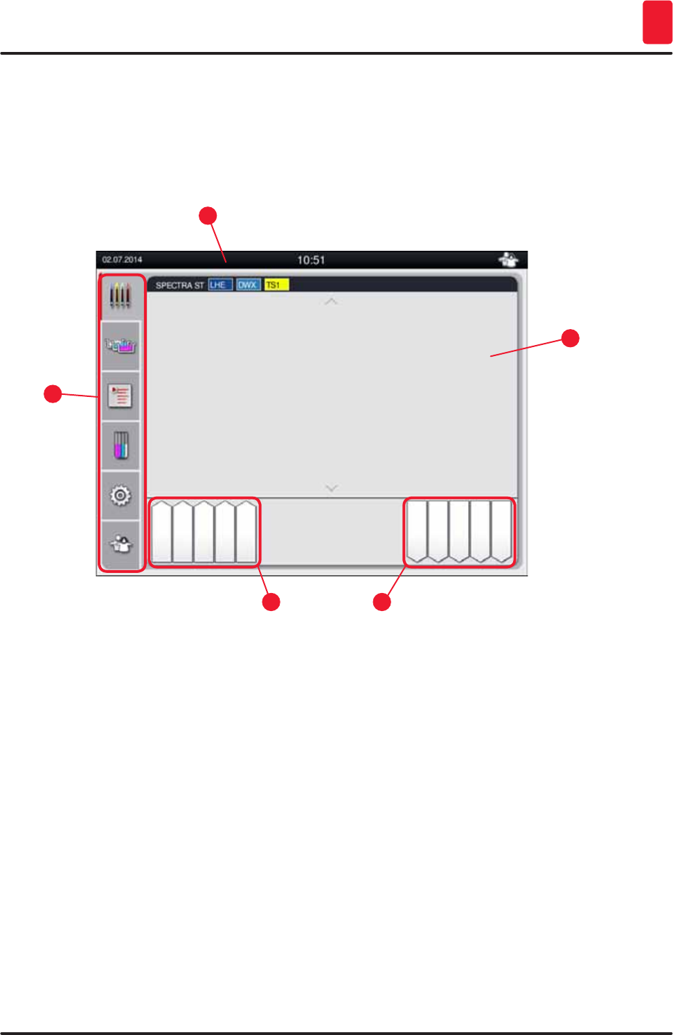
5.1 User interface - overview
The HistoCore SPECTRA ST is programmed and operated via a color touchscreen. The screen appears
as follows after switching on if there is no staining process (program) running.
Fig. 16
1
3
2
4
5
1 Status bar
2 Process status display
3 Output drawer status display
4 Input drawer status display
5 Main menu (→ p. 38 – 5.5 Main menu - overview)
34 Version 1.3, Revision J
Operation
5
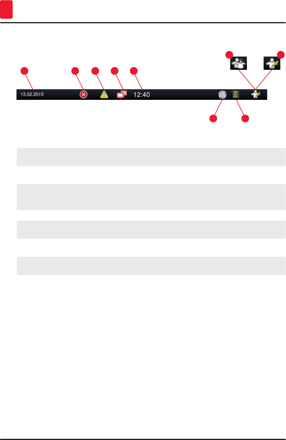
5.2 Elements of the status display
Fig. 17
153
7
2
6
4
89
1 Current date
2 If alarms and error messages are displayed during operation, this alarm symbol appears.
Pressing this symbol allows the last 20 active messages to be viewed again.
3 If warnings and notes are displayed during operation, this notification symbol appears.
Pressing this symbol allows the last 20 active messages to be viewed again.
4 This symbol indicates that a connection to the Remote Care server has been established and
a Leica service technician has access to the screen. The user can end the connection again
by pressing this symbol.
5 Local time
6 The "Remote Care access" symbol indicates that this instrument is connected to the Leica
Remote Care Service via a network connection.
7 The "process" symbol indicates that staining processes are currently active and that racks
may still be in the output drawer.
8 This "user" symbol indicates that the instrument is in user mode, which enables simplified
operation of the instrument without a password.
9 The operation of this instrument in "Supervisor Mode" is displayed by this symbol. This mode
provides additional operation and adjustment options for trained staff. Access to this mode is
password-protected.
35
HistoCore SPECTRA ST
Operation 5
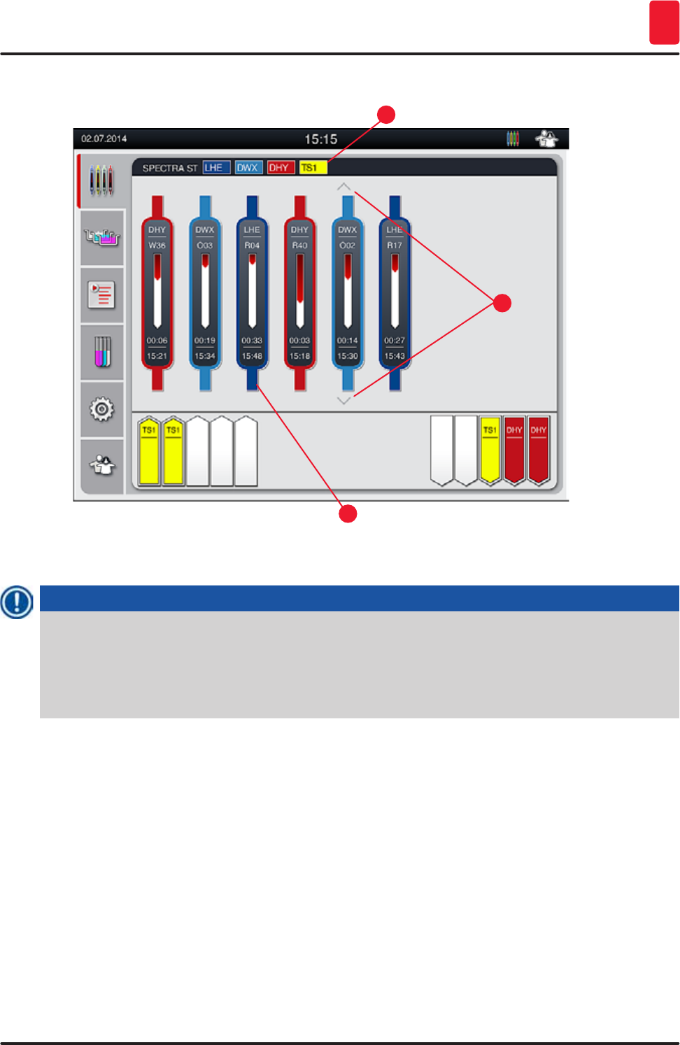
5.3 Process status display
Fig. 18
1
3
2
The main window (→ "Fig. 18") displays all racks (→ "Fig. 18-3") located in the process.
Note
To display an active staining process, the upper part of the handle is displayed symbolically in the
respective color (→ "Fig. 18-3"). If the number of racks in the process exceeds the maximum that
can be displayed in the main window (max. 9), you can scroll through the display area vertically
using the (→ "Fig. 18-1") key. If one of the buttons is grayed out, it is disabled and there are no other
elements in an area that is not shown.
The title bar of the main window (→ "Fig. 18-2") indicates the instrument type [SPECTRA ST] and lists
the currently bootable staining programs with the defined abbreviations and the color assigned to the
racks.
36 Version 1.3, Revision J
Operation
5
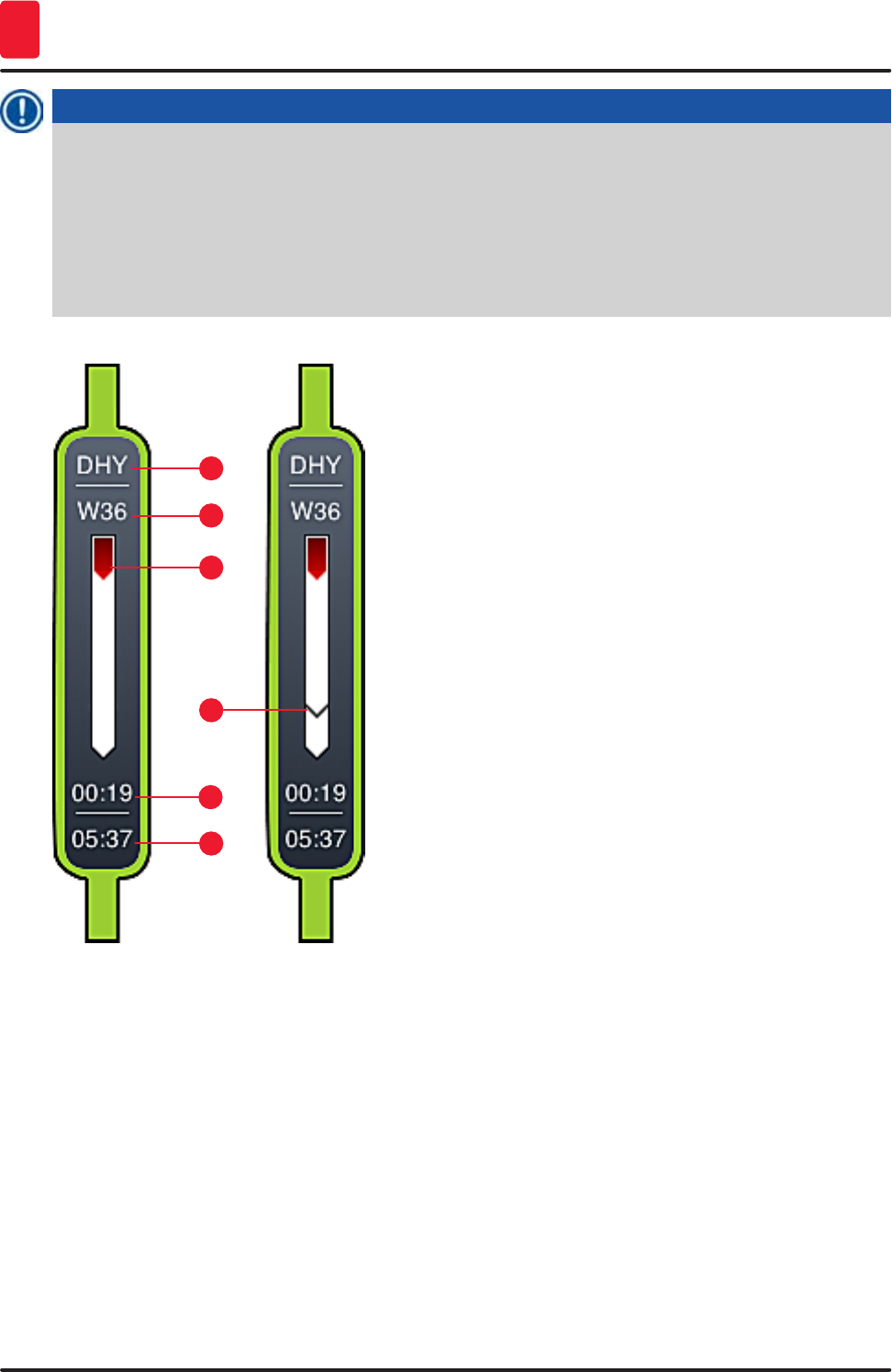
Note
Each ongoing staining process is illustrated by a rack handle symbol. It is shown in the same color
as the actual rack handle. Various information is displayed on the handle symbol (→ "Fig. 19").
If the HistoCore SPECTRA ST staining machine is permanently connected to a
HistoCore SPECTRA CV robotic coverslipper, both devices can be operated as a workstation. This
enables continuous work flow from the staining process up to the removal of the finished cover
slipped slides. The time of transfer to the HistoCore SPECTRA CV is then also displayed in the
process status bar (→ "Fig. 19-6").
Fig. 19
1
5
3
2
6
4
1 Abbreviation of the program name
2 Current position of the rack in the instrument
3 Progress display of the entire staining process
4 Estimated remaining time of the program (hh:mm)
5 Real time at the end of the program
6 Time of transfer to the robotic coverslipper HistoCore SPECTRA CV during operation as
workstation (→ p. 106 – 6.6.5 Operation as a workstation)
37
HistoCore SPECTRA ST
Operation 5
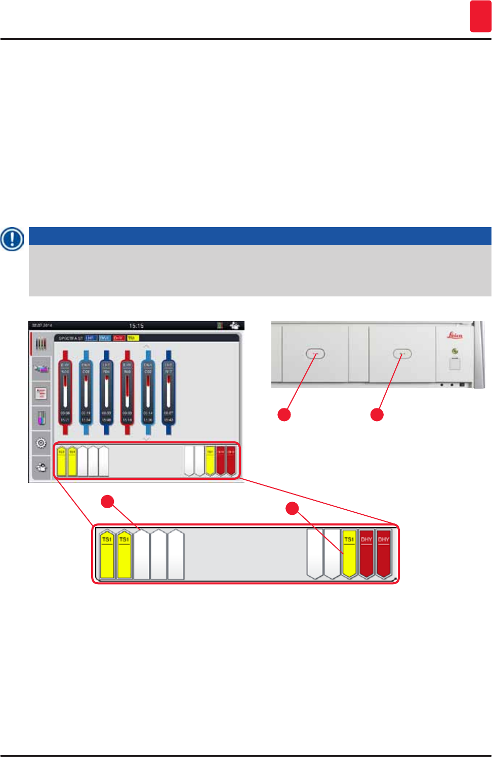
5.4 Displaying the drawers
The lower area of the main window illustrates the status of the input and output drawers.
• The stations displayed with the direction of the arrow pointing into the instrument (→ "Fig. 20-1")
symbolize the input drawer and the stations displayed with the direction of the arrow pointing out of
the instrument (→ "Fig. 20-2") symbolize the output drawer, each with five positions.
• The respective drawer is opened or closed automatically by pressing the drawer button
(→ "Fig. 20-3") or (→ "Fig. 20-4").
• The instrument automatically recognizes if racks are inserted or removed when the drawer is closed.
• The racks located in the input or output drawer are shown on the screen with the respective rack
handle color and the assigned program abbreviation.
• Available positions are shown in white.
Note
The input and output drawers can be opened if the drawer button lights up green (→ "Fig. 20-4").
When racks are being transported out of the input drawer or into the output drawer, the button on
the corresponding drawer lights up red (→ "Fig. 20-3") and the drawer cannot be opened.
1
3
2
4
Fig. 20
38 Version 1.3, Revision J
Operation
5
Warning
Exercise caution when opening or closing the drawers! Crushing hazard! The drawers are
motorized and open automatically when the button is pressed. Do not block the extension range of
the drawers.
5.5 Main menu - overview
The main menu is located on the left side of the display (→ "Fig. 16-5"), which is divided as described
below. This menu is visible in all submenus and allows switching to another submenu at any time.
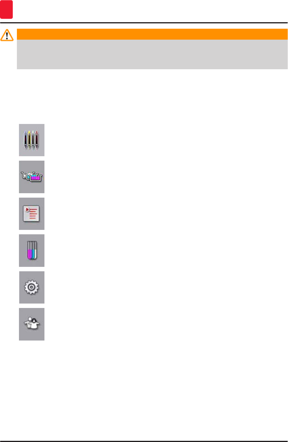
The "Process status display" displays the current status of all racks in progress. Here,
the respective handle of the rack is displayed symbolically with the respective color.
This display shows the standard display.
The "bathlayout" displays the top view of all stations within the instrument. The
individual reagent stations are displayed with abbreviations of reagent names, station
numbers and racks in progress.
After activating the "program list", all staining programs available in the instrument are
displayed in list form. The menu enables re-entering and changing staining programs,
their prioritization and the creation of the bathlayout.
After activating the "reagent list", all previously entered reagents are displayed in list
form. The menu enables the modification or re-entering of staining reagents, e.g. for
integrating new staining programs. The reagents must be entered before creating the
program.
Basic settings can be configured in the "Settings" menu. The language version, date
and time as well as oven temperature and other parameters can be adjusted to the local
requirements here.
In the "User Settings" menu, an individual password can be set up to prevent
modifications to the programs and reagent lists by unauthorized persons ("Supervisor
mode"). However, the instrument can be used without a password in "User Mode".
39
HistoCore SPECTRA ST
Operation 5
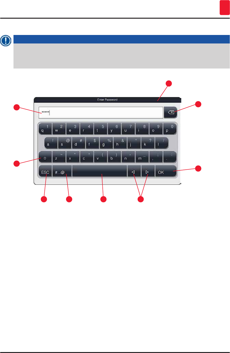
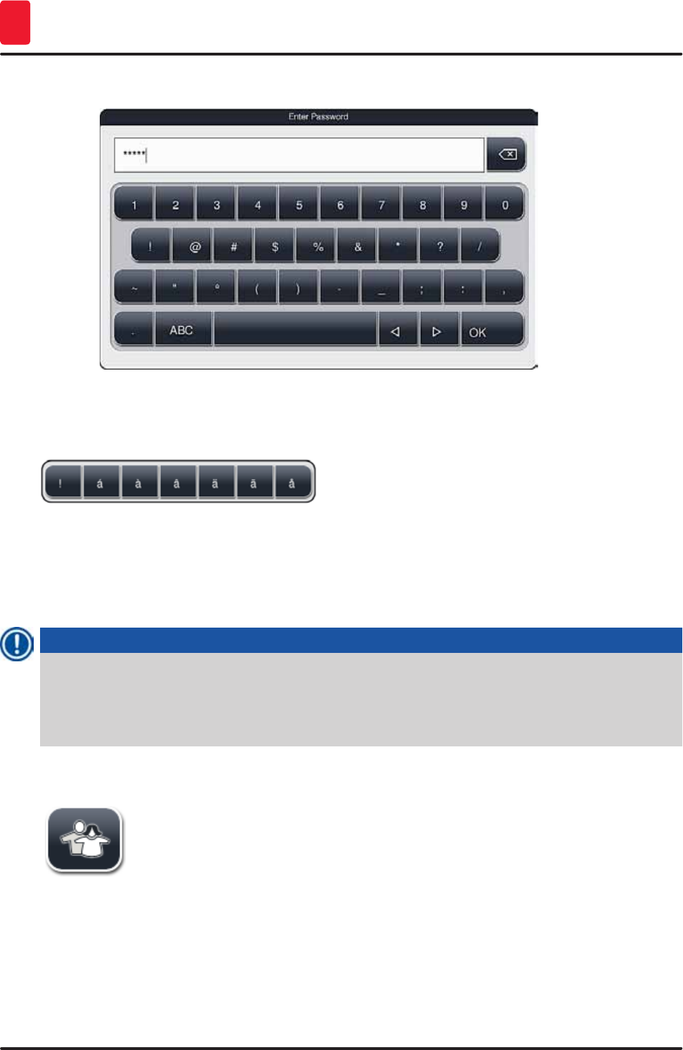
5.5.1 The keyboard
Note
A keyboard appears (→ "Fig. 21") for required entries (e.g. for creating programs, editing programs,
or entering a password). It is operated using the touchscreen.
Note that the keyboard display depends on the configured language.
Fig. 21
1
5
3
7
2
6
4
8
9
1 Title bar
2 Input field
3 Delete most recently entered character
4 Confirmation
5 Move cursor to left or right
6 Space key
7 Special character shift button (→ "Fig. 22")
8 Cancel (entries are not saved!)
9 Upper and lowercase (pushing the button twice activates caps lock, indicated by the button
turning red. Pressing again re-activates lowercase.)
40 Version 1.3, Revision J
Operation
5
Special character keyboard
Fig. 22
Other special characters
Fig. 23
• To enter a special character or umlaut, etc. not included in the special character keyboard
(→ "Fig. 22"), hold the corresponding normal button on the keyboard.
• Example: Holding the standard "a" button brings up other selection options (→ "Fig. 23").
• Select the required character from the new single-line keyboard by pressing it.
Note
The following lengths are applicable for passwords and designations:
• Reagent names: max. 30 characters / reagent abbreviations: max. 10 characters
• Program names: max. 32 characters / program abbreviations: max. 3 characters
• Passwords: min. 4 to max. 16 characters
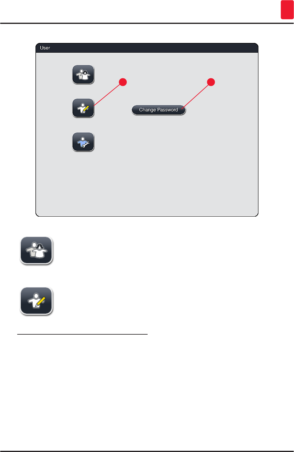
5.6 User settings
This menu can be used to configure the appropriate access level. A distinction is
made between:
• Standard user
• Supervisor (password-protected)
• Service technician (password-protected)
41
HistoCore SPECTRA ST
Operation 5
Fig. 24
12
Standard user:
The standard user does not need a password and can use the completely configured
instrument for all routine applications. It is not possible for this user group to modify
programs and settings.
Supervisor:
Supervisors have the same access options as the standard user, but can also create
programs and perform the instrument setup functions. Therefore, supervisor access
is password-protected.
To activate supervisor mode, proceed as follows:
1. Press the "Supervisor" button (→ "Fig. 24-1").
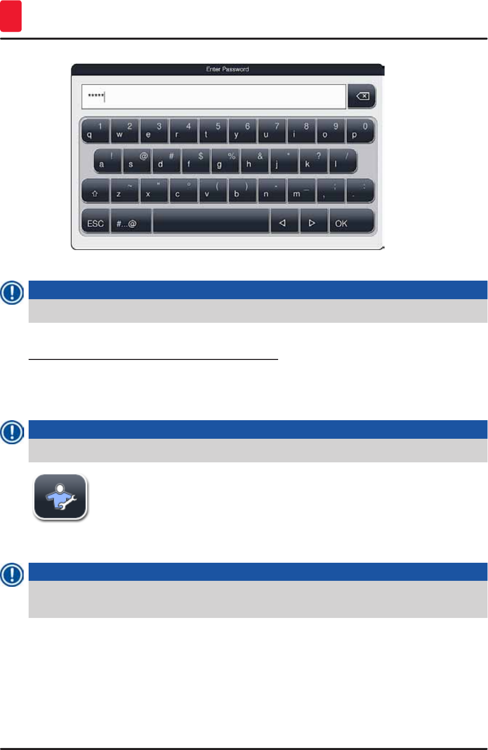
2. A keyboard (→ "Fig. 25") is then displayed which can be used to enter the password.
3. The entry is finished by hitting "OK" and the entered password is checked for validity.
4. The current user status is displayed with the respective symbol in the status bar (→ "Fig. 17")
on the top right.
42 Version 1.3, Revision J
Operation
5
Fig. 25
Note
The password configured at the factory should be changed during the initial setup.
To change the supervisor password, proceed as follows:
1. To change the password, press the "Change password" button (→ "Fig. 24-2") and enter the old
password.
2. Then, enter the new password twice using the keyboard and confirm by hitting "OK".
Note
A password must have at least 4 characters and may have up to 16 characters.
Service technician:
The service technician can access system files and carry out basic settings and
tests.
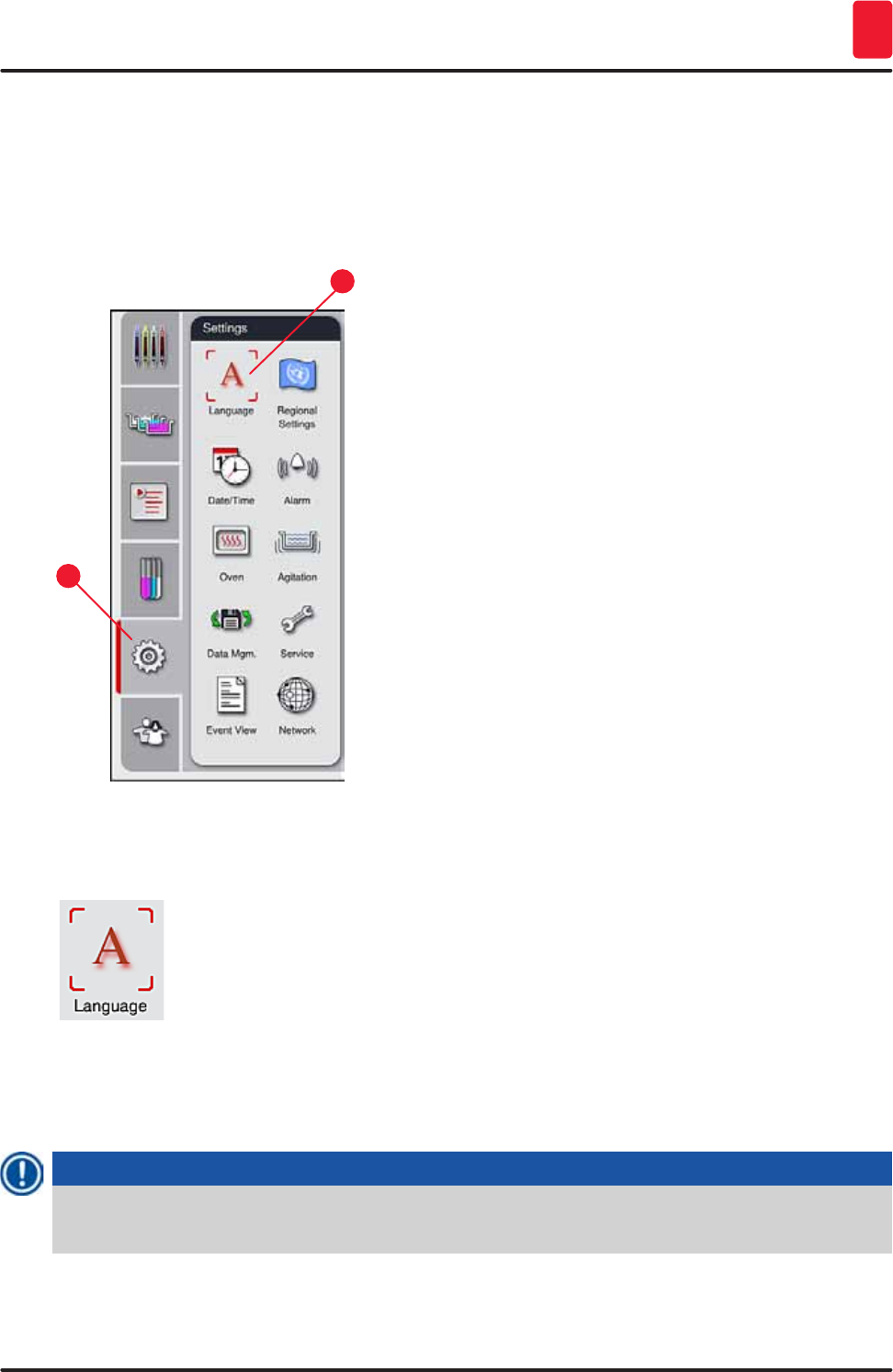
5.7 Basic settings
Note
Changing some of the settings, for example when setting up the instrument for the first time, is only
possible in Supervisor mode (→ p. 41 – To activate supervisor mode, proceed as follows:).
43
HistoCore SPECTRA ST
Operation 5
Touching the gear symbol (→ "Fig. 26-1") opens the "Settings" menu (→ "Fig. 26"). Basic instrument and
software settings can be configured in this menu.
• Touching a symbol (→ "Fig. 26-2") selects it and highlights it in red.
• The respective settings window is displayed in the right area of the screen.
• The individual submenus are described below.
1
2
Fig. 26
5.7.1 Language settings
• The language selection menu is displayed by pushing the symbol for the
"Language" (→ "Fig. 26-2"). This menu contains an overview of all languages
installed in the instrument and allows the desired display language to be selected.
• Select the desired language and confirm by hitting "Save".
• The screen display, messages and labels are displayed immediately in the currently configured
language.
Note
A supervisor or Leica service technician can add other languages using Import (→ p. 49 – 5.7.7
Data management).
44 Version 1.3, Revision J
Operation
5
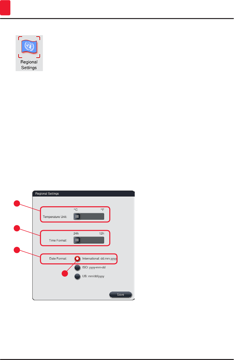
5.7.2 Regional settings
Basic display settings (→ "Fig. 27") can be configured in this menu.
Temperature Unit
• Configure the temperature unit (→ "Fig. 27-1") in Celsius or Fahrenheit. To do so, position the slider at
the desired unit.
Time Format
• The time display (→ "Fig. 27-2") can be changed from a 24-hour display to a 12-hour display (a.m. =
morning/p.m. = afternoon) using the slider.
Date format:
• Configure the date display (→ "Fig. 27-3") to international, ISO or US format by pressing the
corresponding radio button next to the sample format.
• The activated setting is labeled by a red border (→ "Fig. 27-4").
• Pushing the "Save" button saves the settings.
1
3
2
4
Fig. 27
45
HistoCore SPECTRA ST
Operation 5
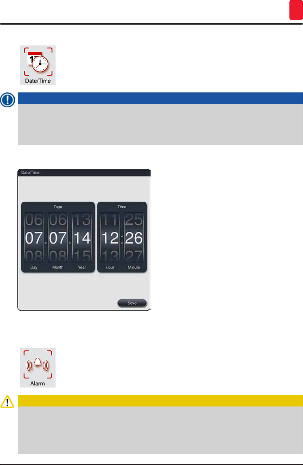
5.7.3 Date and time
The current date and local time can be configured in this menu (→ "Fig. 28") by
rotating the individual rollers.
Note
In the 12-hour display, a.m. (morning) and p.m. (evening) are displayed under the hour digits to
enable a correct setting.
The time and date settings cannot deviate more than 24 hours from the system time configured at the
factory.
• Pushing the "Save" button saves the settings.
Fig. 28
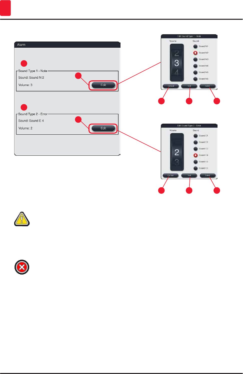
5.7.4 Alarm and signal tones
This menu can be used to select the alarm and signal tones, adjust the volume and
check their functionality (→ "Fig. 29-6").
The current setting for alarm and signal tones is displayed after calling up the menu.
Caution
• After starting the instrument, an alarm sound is played. If this does not occur, the instrument may
not be operated. This protects the specimens and the user. In this case, contact the responsible
Leica service organization.
• The acoustic alarm sounds cannot be disabled. The minimum configurable value for the volume
is 2. The maximum value is 9.
46 Version 1.3, Revision J
Operation
5
1
5
3
7
2
6
4
5 76
Fig. 29
Sound Type 1 - Note (→ "Fig. 29-1")
Signal tones are issued if warning messages or notifications are displayed on the screen. You can
select from a list of 6 sounds. To change the settings, press the "Edit" (→ "Fig. 29-3") button. The volume
can be adjusted incrementally by turning the roller (0 to 9).
Sound Type 2 - Error (→ "Fig. 29-2")
Alarm sounds are issued if an error message is displayed on the screen. This requires immediate
intervention from the user. You can select from a list of 6 sounds. To change the settings, press the
"Edit" (→ "Fig. 29-4") button.
• The volume setting for alarm sounds is adjusted using the "Volume" roller. Six different sounds are
available for the alarm types. The "Test" (→ "Fig. 29-6") button can be used to listen to the respective
sound.
• Pushing the "Save" (→ "Fig. 29-7") button saves the settings. The "Cancel" (→ "Fig. 29-5") button is
used to close the selection window without applying the settings.
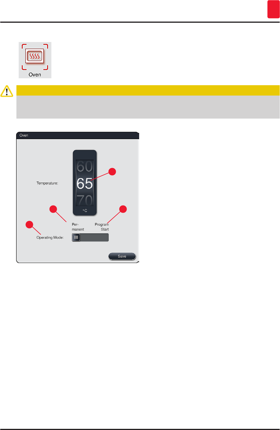
47
HistoCore SPECTRA ST
Operation 5
5.7.5 Oven settings
The temperature of the oven and its operating mode can be configured in the menu
for the oven settings (→ "Fig. 30"). The current oven settings are displayed after
calling up the menu.
Caution
Changing the oven temperature will always have a potential impact on the staining result.
An oven temperature that is set too high can have a negative impact on the sample.
1
3
2
4
Fig. 30
Temperature:
Turning the roller (→ "Fig. 30-1") sets the target temperature of the oven from 40 °C to 70 °C in 5 °C
increments.
Operating mode:
For the operating mode (→ "Fig. 30-2"), you can choose between:
• Heating the oven when starting a program (→ "Fig. 30-4") ("Program start") or
• Starting the oven when switching on the instrument (→ "Fig. 30-3") ("Permanent").
• The slider can be brought to the corresponding position to change the settings.
• Settings are saved by pressing the "Save" button.
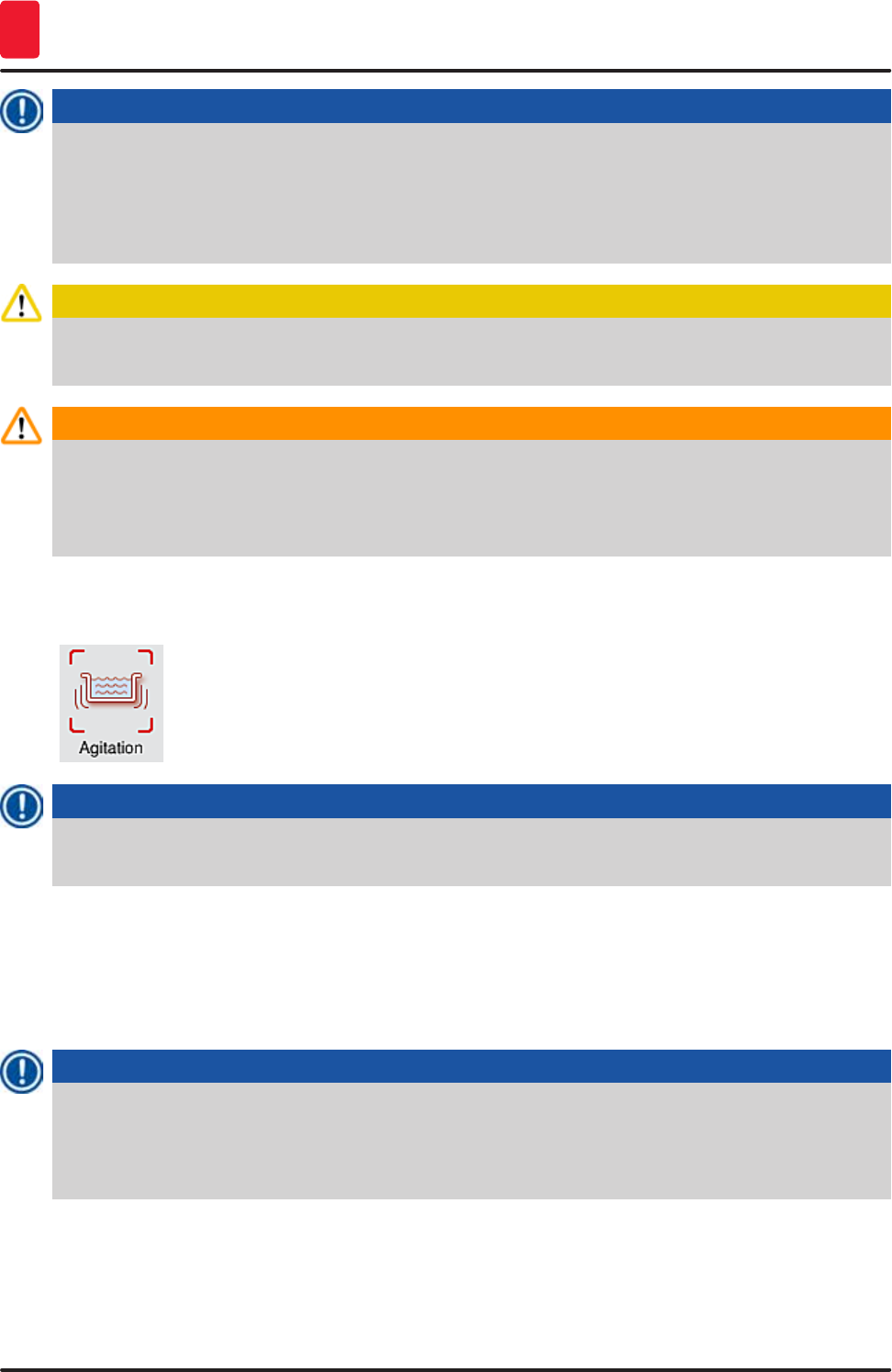
48 Version 1.3, Revision J
Operation
5
Note
• The password-protected user mode "Supervisor" is required to save the changes. In the simple
user mode, the "Save" button is shown in gray and is inactive.
• If Leica staining programs have been integrated into the bathlayout (→ p. 75 – 5.9.9
Creating the bathlayout), the temperature setting cannot be changed. Refer to the information
accompanying the Leica reagent kit for the default temperature.
Caution
We recommend using "Permanent" as a setting to prevent repeated waiting times caused by heating
the oven.
Warning
Due to ambient conditions, the set oven temperature can occasionally deviate from the set value
by –8 °C to +5 °C. Therefore, the set temperature should be selected accordingly for particularly
sensitive specimens (e.g. reducing the set temperature by 5 °C and prolonging the oven step
accordingly).
5.7.6 Movement speed - up/down movement (agitation)
In the "Agitation" menu (→ "Fig. 31"), the speed of up/down movement of the holding
frame for the rack is adjusted. The rack handles lie on the holding frame which
moves up and down in the staining process (agitation).
The current setting is displayed after calling up the menu.
Note
Agitation helps stir the added reagents during ongoing staining processes. The password-protected
"Supervisor" user mode is necessary for adjusting the movement speed (agitation).
Speed:
Rotating the "Speed" (→ "Fig. 31-1") roller can be used to configure the agitation frequency in 5 steps (0=
agitation disabled, 5= highest speed). Higher values mean a higher agitation frequency.
Settings are saved by pressing the "Save" button.
Note
• The agitation speed for user-defined programs can only be changed if no validated Leica
program is active. In this case, the roller is displayed in black and active.
• The agitation is preset (fixed) for validated Leica programs (see Leica Reagents kit instructions
for use). The roller is grayed out and inactive.
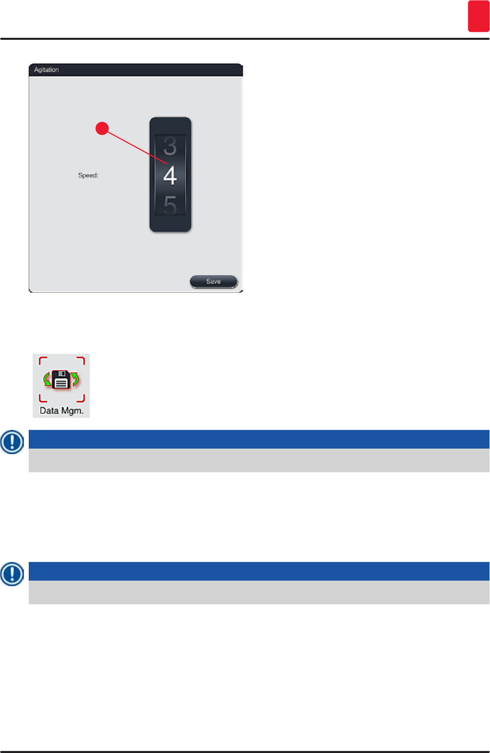
49
HistoCore SPECTRA ST
Operation 5
1
Fig. 31
5.7.7 Data management
In the "Data management" menu (→ "Fig. 32"), the data, settings and event logs
(log files) can be exported and imported. A USB memory stick connected to one of
the USB sockets on the front side of the instrument (→ "Fig. 2-7") is required for all
exports and imports (except for remote software updates).
Note
The USB memory stick used must be formatted as FAT32.
User export (→ "Fig. 32-1")
The "User export" function is used to save information on a connected USB memory stick (→ "Fig. 2-7"):
• A "zip" file with the event logs of the last 30 working days and RMS information in CSV format
• An encrypted "lpkg" file that contains all user-defined programs and the reagent list.
Note
The "lpkg" file cannot be opened and viewed by the user.
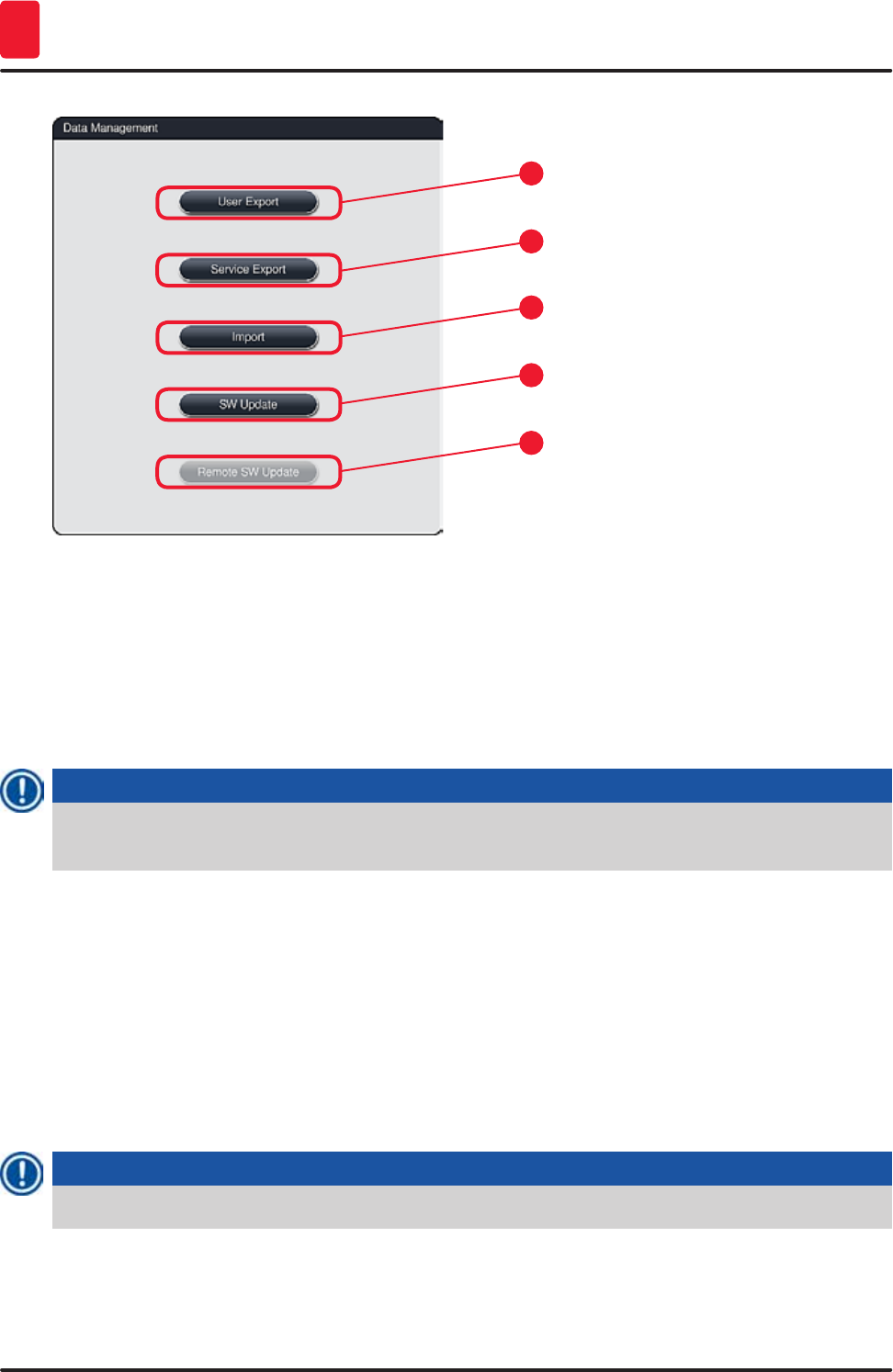
50 Version 1.3, Revision J
Operation
5
1
3
2
4
5
Fig. 32
(→ "Fig. 32-3") User-defined programs and the reagent list can be transfered to another
HistoCore SPECTRA ST with the identical configuration via the "Import" function.
• The message "User data is being exported..." is displayed during the data export.
• The message "Export successful" indicates to the user that the data transfer is finished and the USB
memory stick can be removed safely.
• If the message "Export failed" is displayed, an error occurred (e.g. the USB memory stick was
removed too soon). In this case, the export process must be carried out again.
Note
After successfully setting up the instrument, we recommend exporting the data to be able to access
it if the instrument has to be set up again.
Service export (→ "Fig. 32-2")
The "Service export" function is used to save "lpkg" files on a connected USB memory stick
(→ "Fig. 2-7"):
The encrypted "lpkg" file contains a predefined number of event logs as well as the following:
• RMS information
• User-defined programs
• Reagent data
• Additional service-relevant data
Note
The encrypted lpkg file cannot be opened and viewed by the user.
• After pressing the "Service Export" button, a selection menu appears in which the user can select the
desired number of data records to be exported (5, 10, 15 or 30 days).
• Press "OK" to confirm the selection.

51
HistoCore SPECTRA ST
Operation 5
• The message "Service data is being exported..." is displayed for the duration of the data export.
• The message "Export successful" indicates to the user that the data transfer is finished and the USB
memory stick can be removed safely.
• If the message "Export failed" is displayed, an error occurred (e.g. the USB memory stick was
removed too soon). In this case, the export process must be carried out again.
Import (→ "Fig. 32-3")
Note
The password-protected user mode "Supervisor" is required for importing.
If one or more files are present in the selection dialog, you can use the file name to assign the
save date and instrument serial number. Select the file you want to import and press "OK" in the
subsequent message on the screen.
The instrument software makes sure that no existing Leica programs and reagents are overwritten
during an import of data (programs and reagents). Redundant abbreviations for programs and
reagents, as well as redundant reagent names, are automatically replaced by a placeholder or a
placeholder is added to them. In the case of redundant specimen slide handle colors, the color of
the imported program is set to white.
Specimen slide handle color:
• If a program is imported whose specimen slide handle color already has an assigned program,
this color is replaced with white when imported.
Program name abbreviation:
• If a program is to be imported which has an abbreviation that is already used for an existing
program, the software automatically replaces this abbreviation with a placeholder. The written-
out program name remains the same.
• Abbreviation of the existing program: PAS
• Changed abbreviation of the imported program: +01
Reagent name and reagent name abbreviation:
• If a reagent is imported which has a name and/or abbreviation that is already in use, the
software automatically adds a placeholder ("_?").
• Existing reagent name: 100 % Alcohol Dehyd 1 S
• Changed reagent name of the imported reagent: 100 % Alcohol Dehyd 1 S_?
• Existing abbreviation 100Dhy 1S
• Changed abbreviation of the imported reagent: 100Dhy 1+01
Imported programs and reagents can be integrated into the bathlayout even with placeholders. They
can be renamed later.
Caution
When importing data from a USB memory stick, all user-defined programs and reagents previously
located on the instrument are overwritten and replaced by the imported data. It is not possible
to select individual files for the Import! Leica recommends using this function only for importing
backups or installing an additional HistoCore SPECTRA ST with the same parameters.
52 Version 1.3, Revision J
Operation
5
The "Import" function enables the data import of the encrypted program and reagent list, additional
validated Leica programs and additional language packages from a connected USB memory stick.
This data can also be used to equip another HistoCore SPECTRA ST with the same data using the
Export/Import function.
• To do this, insert the USB memory stick with the previously exported data into one of the USB sockets
on the front side of the instrument (→ "Fig. 2-7").
• Then, select the "Import" function. The data is scanned.
• A message confirms the successful import of the data.
Warning
In general, creating a new bathlayout is required when using the "Import" function (and when
importing a new Leica staining program). All Leica reagents currently in the instrument will expire
and must be replaced by a new, corresponding Leica reagent kit.
Software update (→ "Fig. 32-4")
If software updates and additional language packages are available, these may be run or installed as
follows in the "Supervisor" user mode or by a service technician authorized by Leica.
Carrying out a software update
1. Copy the file for a software update onto a USB memory stick formated with FAT32.
2. Plug the USB memory stick into in one of the two USB slots (→ "Fig. 2-7") on the front of the
instrument.
3. Subsequently, change to the "Data management" menu and click on "Software update"
(→ "Fig. 32-4").
4. The software update is started.
A message notifies the user of a successful update.
Warning
If the update cannot be carried out successfully, this is reported to the user. If the cause is not
obvious, please contact a responsible Leica service organization.
Note
Lab-specific settings are not deleted when updating the software for the HistoCore SPECTRA ST.
After a software update, the instrument must be checked for proper operation.
Remote software update (→ "Fig. 32-5")
This function enables software updates over a connected network. For this purpose, the instrument
must be integrated into the Leica Remote Care maintenance and diagnostic system.
• The new software version is loaded automatically as soon as it is available for this instrument. Once
the loading procedure has concluded, the button (→ "Fig. 32-5") is shown in black and is activated.
• Pressing the "Remote software update" button starts the automatic update process when the
instrument is idle.
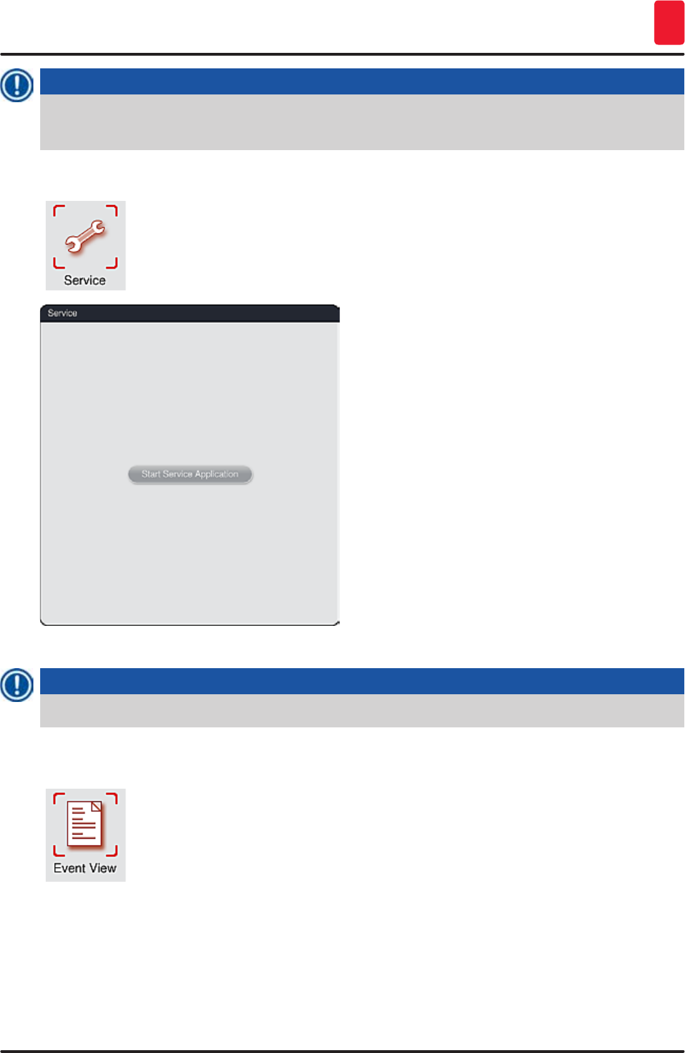
53
HistoCore SPECTRA ST
Operation 5
Note
The user will be notified about an available software update via a message.
The HistoCore SPECTRA ST software is updated; lab-specific settings are not deleted.
5.7.8 Service access
This menu (→ "Fig. 33") gives Leica-authorized service technicians access to
technical functions for diagnostics and repairs to the HistoCore SPECTRA ST.
Fig. 33
Note
Access to the service software is locked for all other user groups.
5.7.9 Event viewer
A separate log file is created for each day that the instrument was switched on.
This file can be called up by selecting the "DailyRunLog" file in the event viewer
(→ "Fig. 34").
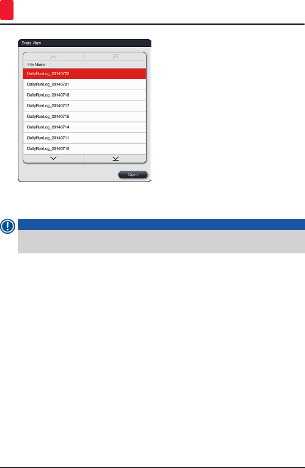
54 Version 1.3, Revision J
Operation
5
Fig. 34
• In the event viewer, an event log can be selected from a list of available logs and called up by
pressing the "Open" button.
Note
The file name is supplemented by adding the respective creation date in ISO format, which makes
organization easier. The file is created in the configured language.
• All event entries begin with a time stamp (→ "Fig. 35-1"), which indicates the date and time when the
entry was created.
• The title bars of the event viewer also indicate the serial number (→ "Fig. 35-2") and the currently
installed software version (→ "Fig. 35-3") of the HistoCore SPECTRA ST.
• You can scroll up and down in the list and the log file using the arrow keys (→ "Fig. 35-4"). Pressing
the left button allows you to scroll through the event viewer page by page. Pressing the right button
takes you to the beginning or the end of the event viewer.
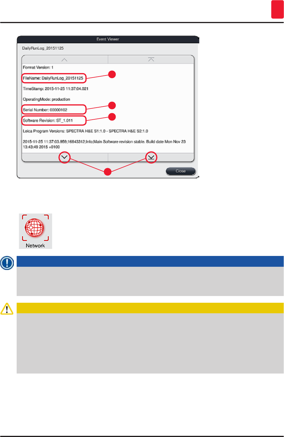
55
HistoCore SPECTRA ST
Operation 5
1
3
2
4
Fig. 35
5.7.10 Network settings
This menu can be used to configure the network parameters for connecting the
instrument to a network.
Note
Leica service organizations can access the instrument's technical data via a service network
(Remote Care) for diagnostic purposes and install software updates. The user can terminate an
existing Remote Care connection by pressing the corresponding symbol (→ "Fig. 17-4").
Caution
• The instrument may only be connected to an available network, for example during the initial
installation, by a service technician authorized by Leica in cooperation with the local IT
department.
• Remote Care uses the TCP/IP network protocol and, at the user level, https (128-bit encrypted).
• If the network connection is interrupted (e.g. the network cable is removed), then the instrument
has to be shut down in a controlled manner (→ p. 31 – 4.5 Switching the instrument on and off),
the network cable has to be plugged in again, and the instrument has to be restarted.
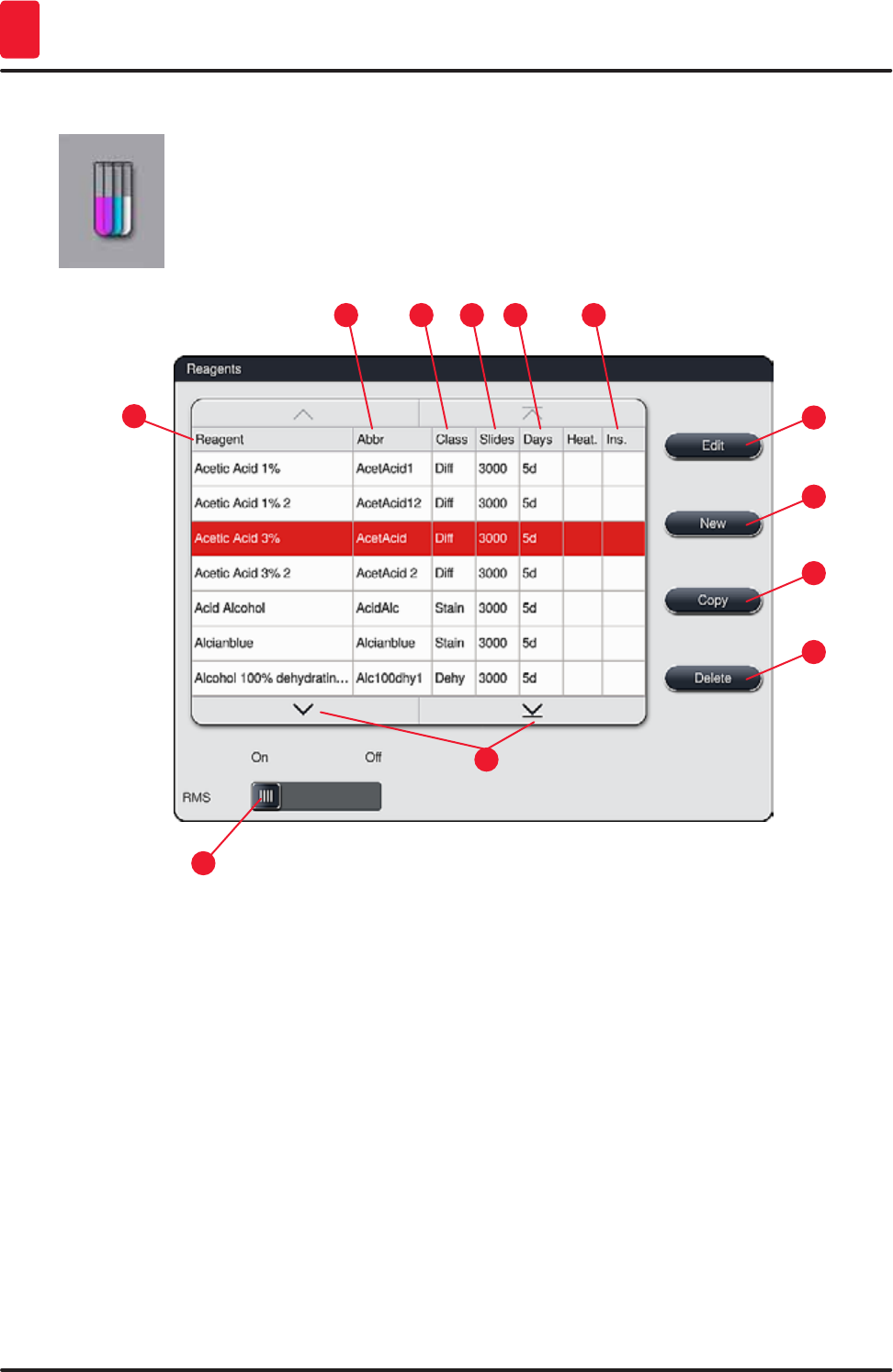
56 Version 1.3, Revision J
Operation
5
5.8 Reagent list
Open the reagent list by pressing the adjacent button. This displays all defined
reagents in alphabetical order.
Fig. 36
1
9
53
11
72
10
4
13
8
14
1Reagent name 8 Edit selected reagent
2Abbreviation of the reagent name 9Create a new reagent
3Process class 10 Copy selected reagent
4Maximum number of specimen slides 11 Delete selected reagent
5Maximum period of use
13 Activate/deactivate RMS
7Insert for special dye yes/no 14 You can scroll through the reagent list using
the arrow keys.

57
HistoCore SPECTRA ST
Operation 5
Note
• When setting up the instrument, the reagent list only contains reagents from the preinstalled
Leica programs.
• Additional reagents can be added or properties of the reagents can be changed as needed in the
reagent list.
• Creating or editing a reagent requires "Supervisor" mode. The "User" status only allows reagent
data to be displayed.
• Reagents that have been integrated into the bathlayout in active programs cannot be deleted
from the reagent list.
Caution
• The "RMS: On – Off" slider ((→ "Fig. 36-13") allows the reagent management system = RMS
(→ p. 89 – 6.3 Reagent management system (RMS)) to be switched on or off. This system
controls reagent consumption monitoring. We always recommend keeping the RMS switched
on and following the instructions for replacing a reagent. It is not possible to switch off reagent
monitoring for the Leica staining kit reagents.
• Failure to adhere to the specified intervals can have a negative effect on the staining quality. The
RMS only works reliably if the data has been stored by the user correctly in advance.
• The manufacturer assumes no liability for the staining results in case of errors when entering
the reagent data.
• The RMS data of the reagents validated by Leica and their designation can not be edited by the
user.
5.8.1 Defining heated reagent (optional)
Note
A deactivated, heated reagent station cannot be used for long periods again until a new bathlayout
(→ p. 75 – 5.9.9 Creating the bathlayout) has been generated.
You can change from "Permanent" mode to "Program Start" mode (or vice versa) without generating
a new bathlayout.
• To add a new reagent to the reagent list, press the "New" button (→ "Fig. 36-9").
• It opens the entry window (→ "Fig. 39") for the new reagent to be created.
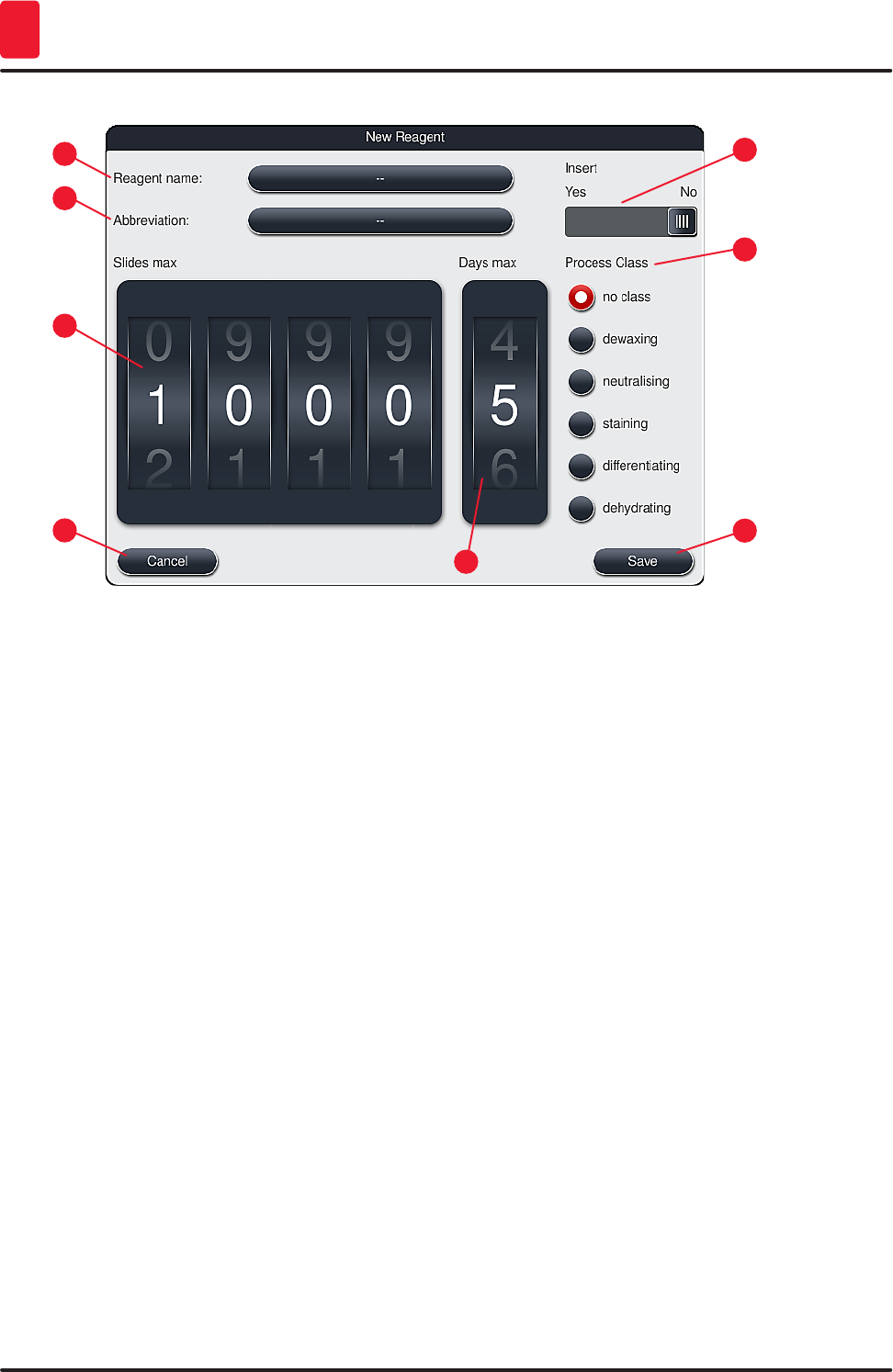
58 Version 1.3, Revision J
Operation
5
15
3
7
2
6
4
8
Fig. 39
The following parameters can be entered:
Reagent name:
Press the "Reagent name" (→ "Fig. 39-1") button and use the on-screen keyboard to enter a unique
reagent name that has not yet been used. You can enter up to 30 characters (including spaces).
Abbreviation:
Press the "Abbreviation" button (→ "Fig. 39-2") to use the on-screen keyboard to enter a unique
abbreviation for the reagent that has not yet been used (maximum 10 characters, including spaces).
Slides max:
The roller (→ "Fig. 39-3") is used to configure the maximum number of specimen slides that can be
processed with this reagent before a reagent change is requested. By rotating the rollers, values
between 1 through 3999 are permitted.
Days max:
The maximum number of days (→ "Fig. 39-4") that the reagent can remain in the instrument is configured
by rotating the roller. Values from 1 through 99 are permitted when entering figures.
59
HistoCore SPECTRA ST
Operation 5
Insert:
If a reagent vessel is equipped with an insert for special staining (→ p. 86 – 6.2.1 Preparation and
handling of reagent vessels) in order to enable a smaller reagent volume, using the rack is only possible
for 5 slides in this vessel. For this purpose, you must set the slide switch to "Yes"(→ "Fig. 39-5").
Using a rack for 30 slides in this vessel is now disabled.
Warning
Using the insert for special staining in one or more reagent vessel (s) requires switching to the
"Yes" position. If the switch is not set correctly for the affected reagent vessel (s), this may cause
a rack for 30 slides to be used in this vessel, which inevitably leads to a serious equipment failure
with possible specimen loss.
Process class:
Assigning the reagents to process classes (→ "Fig. 39-6") (→ p. 60 – 5.8.4 Process classes) is required
since, along with prioritizing programs, it is essential for automatically calculating the individual
positions of the bathlayout (→ p. 74 – 5.9.8 Prioritizing programs for creating the bathlayout).
• Store the entry with the "Save" button (→ "Fig. 39-7") or close the entry window with the "Cancel"
button (→ "Fig. 39-8") without applying the entry.
Note
Subsequently changing a process class is no longer possible after the initial save. The reagent can
only be deleted and re-created or copied and then changed.
5.8.2 Copying a reagent
Note
If a reagent with different parameters is used in HistoCore SPECTRA ST, then an existing reagent
can be copied.
• Select the reagent to be copied in the reagent list (→ "Fig. 36") by tapping it and press the "Copy"
(→ "Fig. 36-10") button.
• It opens the entry window (→ "Fig. 39") for the new reagent to be created.
• Apply the suggested reagent name or overwrite it with a new reagent name.
• The suggested abbreviation can be applied or overwritten with a new abbreviation.
• If necessary, change the parameters for the reagent accordingly or apply the existing parameters.
• Store the entry with the "Save" button (→ "Fig. 39-7") or close the entry window with the "Cancel"
button (→ "Fig. 39-8") without applying the entry.
60 Version 1.3, Revision J
Operation
5
5.8.3 Changing the RMS data for a reagent
Note
If changes are to be made to the RMS data ("Slides max" and/or "Days max"), the following
steps must be carried out so that modified settings are displayed correctly in the station details
(→ p. 94 – Fig. 76).
• Select the reagent to be changed in the reagent list (→ "Fig. 36") by tapping it and press the "Edit"
(→ "Fig. 36-8") button.
• Using the rollers, set the new values for the "Slides max" (→ "Fig. 39-3") and/or "Days max"
(→ "Fig. 39-4") and apply the changes using the "Save" button.
• Note the subsequent message and confirm it with "Ok".
• Then call up the bathlayout and tap the associated reagent station there to select the station by
touching the screen.
• In the station details that appear, press the "Update Reagent" (→ "Fig. 76-10") button.
• The display with the station details is closed, and the RMS data has been applied.
5.8.4 Process classes
Caution
Process classes must be assigned correctly since otherwise there is a risk of delayed work flows
in the staining processes and deviating or inadequate staining results.
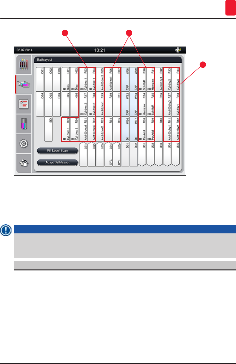
61
HistoCore SPECTRA ST
Operation 5
12
3
Fig. 40
1 The preferred zone for dewaxing reagents is the left side of the bathlayout.
2 The preferred zone for staining solutions or differentiating solutions are the two rows to the left
and right of the rinsing water stations.
3 The preferred zone for dehydrating reagents is the right side of the bathlayout.
Note
No two successive rinsing water steps can be programmed (rinsing water step for distilled water or
vice versa). If the sequence of the program steps is to occur in this way, one of the steps has to be
defined as a reagent assigned to a process class (e.g. neutralizing).
Process class Description Example of reagents
Dewaxing
(Dewaxing)
• Solvents that remove the paraffin and,
following the paraffin removal, the
subsequent graded alcohol series, at the
beginning of a staining program.
• Xylene
• Xylene substitute
• Graded alcohol series: 100 %,
95 %, 70 % alcohol

62 Version 1.3, Revision J
Operation
5
Process class Description Example of reagents
Neutralizing
(Neutralizing)
• Reagents that have little or no effect on the
stain application or the stain development
and that have a roughly neutral pH value.
• Example: Distilled water step before a
staining step.
• Distilled water
(demineralized)/fresh water
(not in rinsing water stations!)
• Thinners with distilled water
• Aqueous alcoholic solutions
(e.g. 70 % ethanol)
Staining
(Staining)
• Staining solutions
• Wood stains
• Oxidizing agents (e.g. Periodic acid of the
PAS dye)
• All staining solutions
• Wood stains and oxidizing
agents
Differentiating
(Differentiating)
• Reagents that remove excess color from
the product.
• Reagents that are required for the stain
development or a color change.
• HCl solution (alcoholic or
aqueous)
• Acetic acid
• Ammonia water
• Scott's tap water
• Bluing solution
• Blue Buffer
• Lithium carbonate
• Alcohols (various
concentrations)
Dehydrating
(Dehydrating)
• Reagents of the ascending alcohol series,
at the end of a staining program.
• Subsequent solvent steps (xylene or
xylene substitute), at the end of a staining
program, for preparing the coverslipping
operation.
Dehydration:
• Ascending alcohol series:
70 %, 95 %, 100 % alcohol
Preparing the coverslipping
operation:
• Xylene
• Xylene substitute
No class
(no class)
Reagents that do not require any special assignment in the bathlayout
Caution
The following must be observed for preparing the coverslipping operation:
• The solvent used at the end of the program and in the following coverslipping process must be
compatible with the coverslip mountant.
63
HistoCore SPECTRA ST
Operation 5
Note
The correct assignment of the process classes is necessary so that the optimal bathlayout can be
calculated and long transport paths and times can be avoided.
Basic rules of automatic creation of the bathlayout include:
• The transfer from the left vessel field to the right vessel field should occur via a rinsing water
station whenever possible.
• Programs that do not contain a rinsing water station as a step use the dry transfer station for this
transfer.
• Staining reagents that require a subsequent rinsing water step are positioned adjacent to the
rinsing water vessels (→ "Fig. 40").
• Reagents for which "No class" has been assigned as a process class can be set at any position
during the automatic creation of the bathlayout.
• Instead of the "No class" assignment, we recommend assigning these reagents to either the
"Differentiating" or "Neutralizing" project class so that adjacent stations in the bathlayout can be
taken into account for series.
5.9 Staining programs
The list of the staining programs installed on the HistoCore SPECTRA ST is opened by
pushing the "Programs" button.
A distinction is made between two types of staining programs:
• Preinstalled Leica staining programs (→ p. 66 – 5.9.2 Leica staining programs
(preinstalled))
• User-defined staining programs (→ p. 68 – 5.9.4 User-defined staining programs)
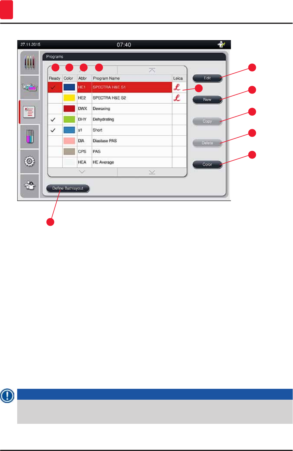
64 Version 1.3, Revision J
Operation
5
1
9
5
3
11
7
2
10
64
8
Fig. 41
1 A check in this column means that the program is taken into account in the current bathlayout.
2 Assigned program color
3 Program abbreviation
4 Program name
5 Preinstalled Leica program
6 Edit program
7 Create a new program
8 Copy selected program
9 Delete selected program
10 Assign a color to the selected program
11 Define bathlayout
5.9.1 Assigning a rack handle color to a staining program
Note
A rack handle color must be assigned to each program.
The assignment of rack handle colors to programs requires the "Supervisor" user status.
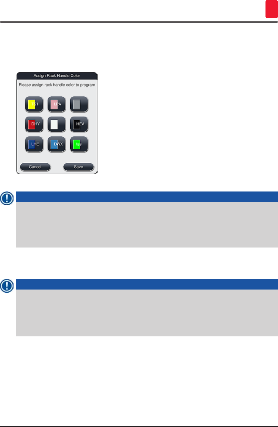
65
HistoCore SPECTRA ST
Operation 5
• To assign a rack handle color to a program, tap the corresponding program in the program list
(→ "Fig. 41") to select it.
• Pressing the "Color" button (→ "Fig. 41-10") displays a selection field (→ "Fig. 42") that allows
assignment of the rack handle color to the selected program.
Fig. 42
Note
All available colors are displayed in (→ "Fig. 42"). If an abbreviation is entered in the color field, this
color has already been assigned to a program.
If an already assigned color is selected, a dialog box appears with a confirmation prompt indicating
that the existing assignment will be undone. This can be confirmed with "OK" or aborted with
"Cancel".
• Select a color that has not been assigned previously.
• "Save" is used to assign the color and close the dialog.
• "Cancel" is used to close the dialog without applying the changes.
Note
If there are not enough rack handles available in one color, then a rack handle in white, the so-
called wildcard color, can be used.
When inserting a rack with a white handle, a program selection window opens in which a color
program activated in the bathlayout has to be assigned to the white handle for this program only.
After termination of the selected program, this assignment expires again.
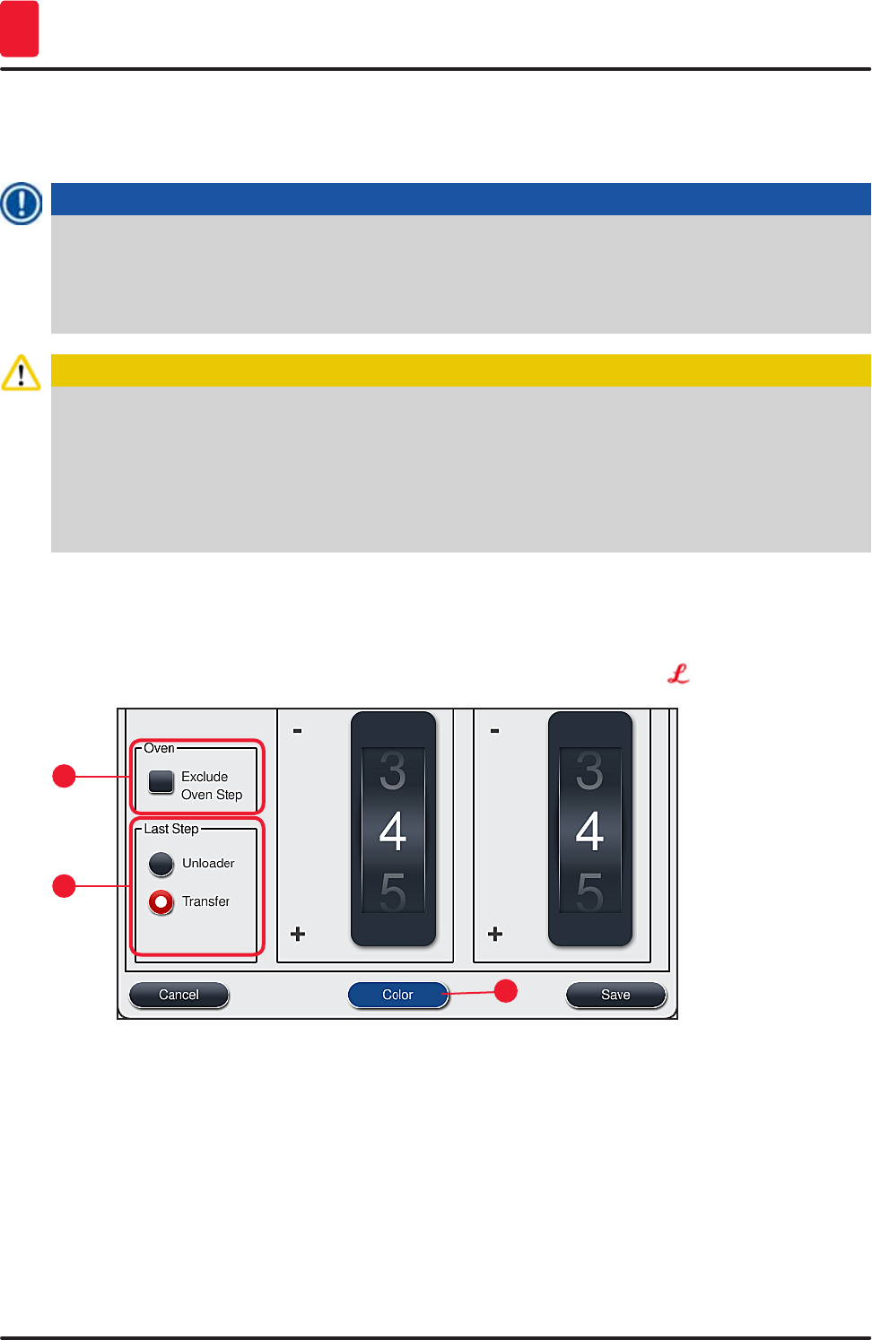
66 Version 1.3, Revision J
Operation
5
5.9.2 Leica staining programs (preinstalled)
Designation of the reagent kits
Note
In the following section, the HistoCore SPECTRA ST staining systems and programs produced by
Leica are simplified in accordance with the user interface and named with the designation of the
Leica reagent kit and Leica staining programs.
New Leica staining programs can be obtained from the responsible Leica sales company.
Caution
The instructions for use provided with the Leica reagent kits contains important details regarding
the preset values, logs and necessary amendments, and must therefore be strictly observed.
Therefore, the instructions for use must be observed!
To import new Leica staining programs, proceed as described in chapter (→ p. 49 – 5.7.7 Data
management). New Leica programs are added to the existing program list (→ p. 63 – 5.9 Staining
programs). No data is deleted.
• Leica staining programs are preinstalled at the factory and have had their function and staining
properties tested. They ensure consistent staining quality for a specified number of slides.
• Leica staining programs are labeled in the last column with a cursive Leica- (→ "Fig. 41-5").
1
3
2
Fig. 43

67
HistoCore SPECTRA ST
Operation 5
Note
• Leica staining programs require the use of the specific Leica reagent kit.
• Leica staining programs cannot be copied, meaning that a Leica staining program can only be
entered into the program list once.
• The individual program steps of the Leica staining program cannot be shown, edited, copied or
deleted.
• A rack handle color (→ "Fig. 43-3") can be assigned to the Leica staining program.
• If the Leica staining program provides for it, the oven step can be enabled or disabled
in Supervisor mode (→ "Fig. 43-1") and the "Unloading station" or the "Transfer station"
(→ "Fig. 43-2") can be defined as the final step. The "Transfer station" is only then displayed if the
HistoCore SPECTRA ST is operated with a HistoCore SPECTRA CV as a workstation.
• Reagents (e.g. xylene, alcohol) that are used in a Leica staining program cannot be deleted.
Warning
• If a paraffin removal step is not provided as the first step for the Leica staining program, then the
oven step (→ "Fig. 43-1") (→ "Fig. 44-1") must not be enabled, as otherwise the specimens could
be destroyed!
• The fixed oven temperature for the Leica staining programs is also used for user-defined staining
programs and cannot be individually adapted.
5.9.3 Adapting the Leica H&E staining program
Note
• With the Leica H&E staining program, the staining intensity can be adjusted for hematoxylin and
eosin in Supervisor mode. Other Leica staining programs do not allow for any adjustments to the
staining intensities.
• If the Leica staining program provides for it, the oven step can be enabled or disabled
(→ "Fig. 44-1").
• For Leica staining programs, the transfer to a connected robotic coverslipper
HistoCore SPECTRA CV can be chosen as the final step by selecting "Transfer station"
(→ "Fig. 44-4") or by setting aside the already-stained rack in the output drawer (→ "Fig. 44-3").
• Adjustments and changes to Leica staining programs and user-defined staining programs can
only be configured if no staining processes are active and all racks have been removed from the
instrument.
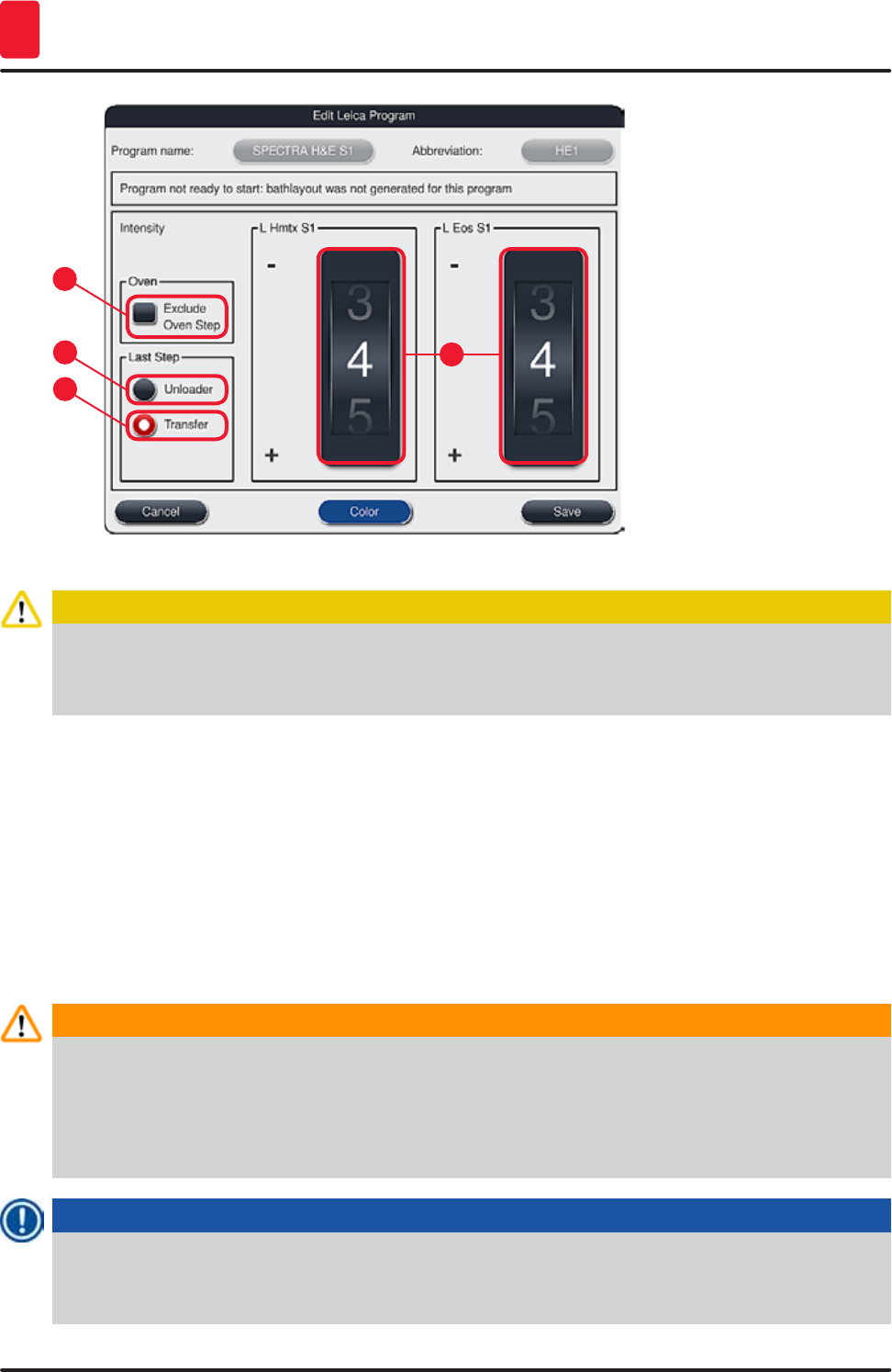
68 Version 1.3, Revision J
Operation
5
Fig. 44
1
32
4
Caution
After the user adjusts the staining intensity, the staining results must be checked with a control
slide containing representative tissue sections before the settings are used for patient specimens
for clinical diagnostics.
Select the Leica program in the program list and press "Edit" (→ "Fig. 41-6"). A dialog window opens in
which the settings can be configured.
• The staining intensity values can be set by turning the rollers (→ "Fig. 44-2"). Smaller numerical values
cause a lighter staining intensity; higher numerical values cause a darker staining intensity.
• A handle color must be assigned to the program (→ p. 64 – 5.9.1 Assigning a rack handle color to a
staining program).
• Use "Save" to save the settings and close the dialog.
• Use "Cancel" to close the dialog without saving changes.
5.9.4 User-defined staining programs
Warning
• Leica can provide neither testing nor a warranty for user-defined programs.
• The testing of these staining programs using the respectively used reagents and adjusted
temperatures must be carried out in the lab by the user. To do so, the staining result has to be
checked with a specimen cycle (trial sections) before the program is used for patient specimens
for clinical diagnostics.
Note
A new program can be created with the "New" (→ "Fig. 45-1") or "Copy" buttons (→ "Fig. 45-2").
Creating, copying or editing a program requires "Supervisor" mode. The "User" status only allows
program steps to be displayed.
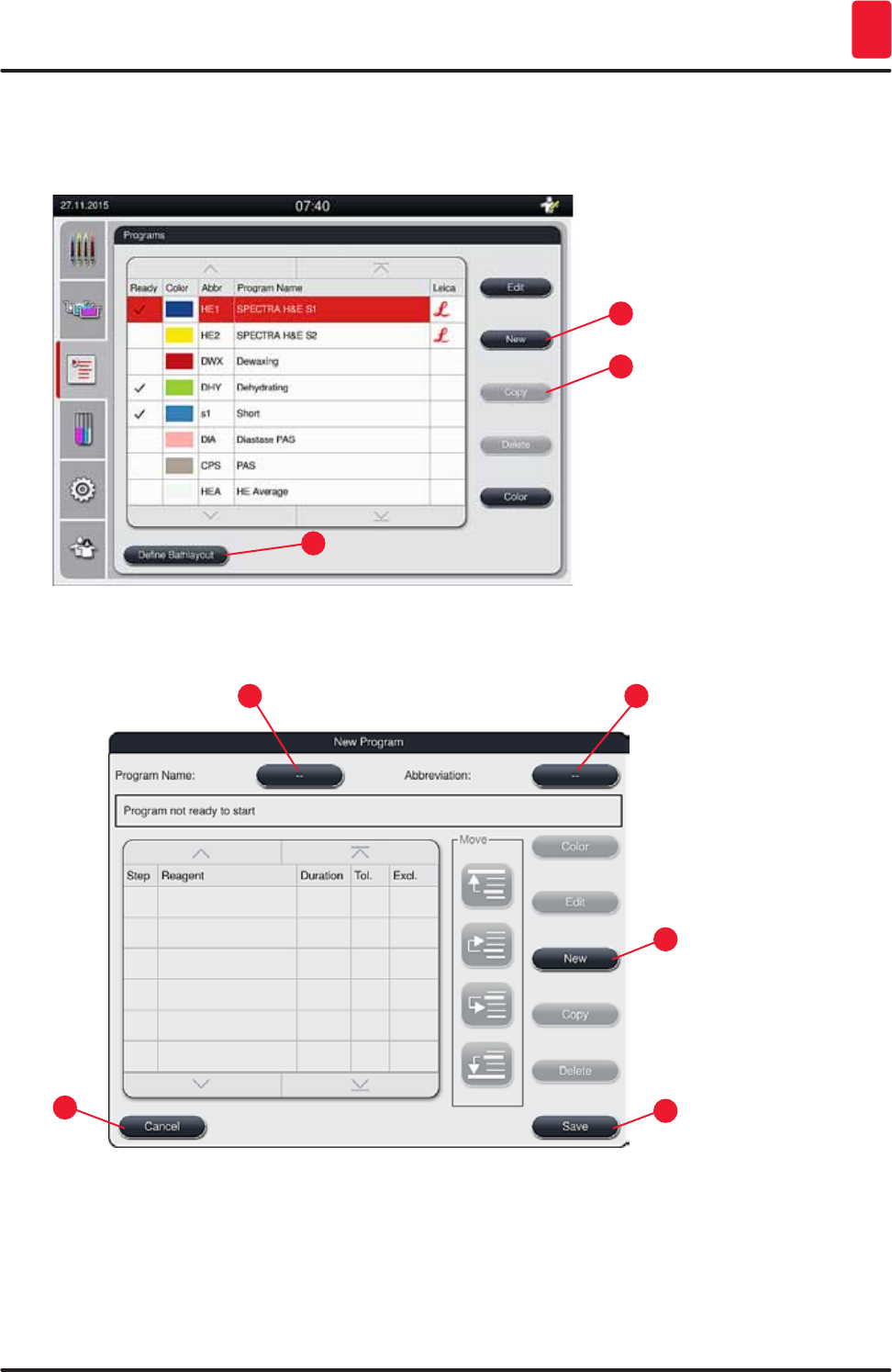
69
HistoCore SPECTRA ST
Operation 5
5.9.5 Creating or copying a new staining program
• Press the "New" button (→ "Fig. 45-1") in the list view of the program.
1
3
2
Fig. 45
• A new program window opens (→ "Fig. 46").
1
5
32
4
Fig. 46
Two empty buttons are shown in the upper area of this window. They are intended for the program
name and its abbreviation.
• Press the "--" button behind the "Program Name" designation (→ "Fig. 46-4"). An input mask with
keyboard appears.
• Enter the program name and apply the name entered with the "OK" button.
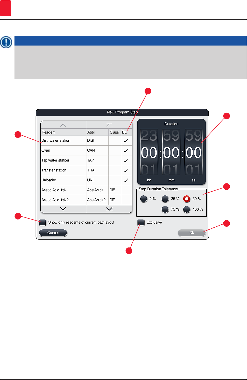
70 Version 1.3, Revision J
Operation
5
Proceed as described above to enter the "Abbreviation" (→ "Fig. 46-5").
Note
To create a new staining program, multiple program steps are added to the program in sequence.
Please note: User-defined programs cannot be saved with the designation "SPECTRA" as the
program name. A message notifies the user of this when attempting to save. Saving is only possible
after entering a different program name.
1
5
3
7
2
6
4
Fig. 47
• After a new program has been created, press the "New" button (→ "Fig. 46-1").
• A window opens for defining the program step (→ "Fig. 47").
• The reagents already predefined by the user are listed in the area on the left (→ "Fig. 47-1"). Tap the
reagent to select it.
• Turning the rollers (→ "Fig. 47-2") in the area on the right defines the reaction time (hh/mm/ss) of the
specimens in the reagent .
• The valid setting range goes from 1 second up to 23 hours 59 minutes and 59 seconds.
• Here, the permitted "Tolerance" (→ "Fig. 47-3") of the step is configured. If an exact program step is
needed that does not allow any temporal extension of the specified time, the tolerance 0 % must be
selected. The tolerance can be selected in 25 % increments up to a maximum expansion of 100 %, i.e.
the instrument can extend the step to twice the length of the configured time, if needed.

71
HistoCore SPECTRA ST
Operation 5
Note
The times for the individual program steps are composed of the programmed step times plus the
configured tolerances. If tolerance configurations for a program step are > 0 %, the remaining
station times and expected remaining time for the program may be exceeded.
Copying a program
Note
If you want to use an existing program with other parameters, then the program can be copied.
• Select the program to be copied in the list view (→ "Fig. 45") by tapping it and press the "Copy"
(→ "Fig. 45-2") button.
• It opens the entry window (→ "Fig. 46") for the new program to be created.
• Apply the suggested program name or overwrite it with a new program name.
• Then, enter an abbreviation.
• If necessary, change/edit the individual steps of the program as needed or add new program steps
(→ "Fig. 46-1") (→ p. 71 – 5.9.6 Inserting or copying a new program step).
• Save the entry with the "Save" button (→ "Fig. 46-2") or close the entry window with the "Cancel"
button (→ "Fig. 46-3") without applying the entry.
5.9.6 Inserting or copying a new program step
Inserting a new program step
Note
A high time tolerance setting is recommended if no negative effects on the staining result are to be
expected. This gives the instrument more room to synchronize steps of multiple programs running at
the same time.
• If a check mark is in the "BL" (→ "Fig. 47-4") column, this means that this reagent is already integrated
into the bathlayout.
• To limit the display to reagents that are already actively used in the bathlayout, enable the radio
button "Show only reagents of current bathlayout" (→ "Fig. 47-5").
• If the "Exclusive" (→ "Fig. 47-6") box is activated, the selected reagent can only be used for the
created program and no other program is available for selection.
• The program step entry is completed with "OK" (→ "Fig. 47-7").
• Depending on need, other program steps can be added in the same way until all staining process
steps are illustrated in the program.
Note
A program must always be concluded with a final target station step. As the final step, the output
drawer or, in case HistoCore SPECTRA ST is permanently connected as a workstation with a
HistoCore SPECTRA CV, the transfer station must be selected.
A warning message (→ "Fig. 48") indicates that it is not possible to save the program without defining
the target station as the last step.
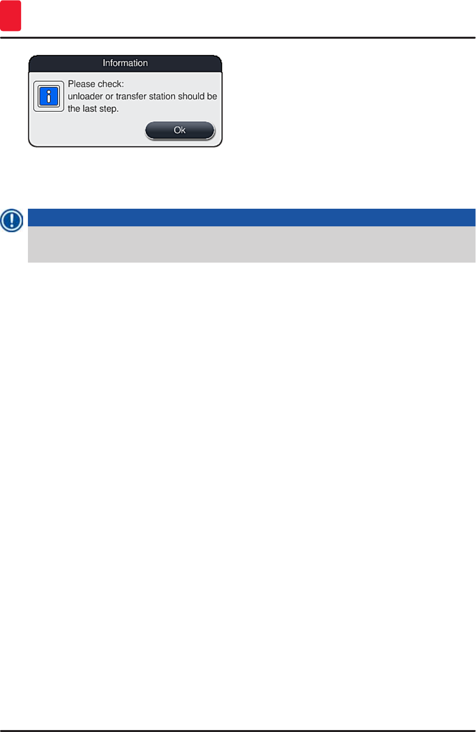
72 Version 1.3, Revision J
Operation
5
Fig. 48
Copying a program step
Note
When creating or modifying a program, a program step can be copied with the previously set
parameters and modified to a reagent which is currently in the reagent list.
• Tap the respective program step and press the "Copy" button (→ "Fig. 49-5").
• It opens the "Edit program step" window (→ "Fig. 49").
• If a reagent with only one instance present has been selected, a message notifies the user of this
fact. In this case, a different reagent is to be selected for the program step.
• The parameters (tolerance, duration and exclusivity) of the originally selected program step are
retained.
• If necessary, change the parameters for the program step accordingly or apply the existing
parameters and press the "Ok" button.
• The program step is placed at the end of the program.
• Reorder the program step as described in (→ p. 72 – 5.9.7 Re-sorting program steps).
5.9.7 Re-sorting program steps
• The program step is highlighted in red upon selection. Now the "Move" buttons (→ "Fig. 49-1")
(→ "Fig. 49-2") (→ "Fig. 49-3") (→ "Fig. 49-4") are active.
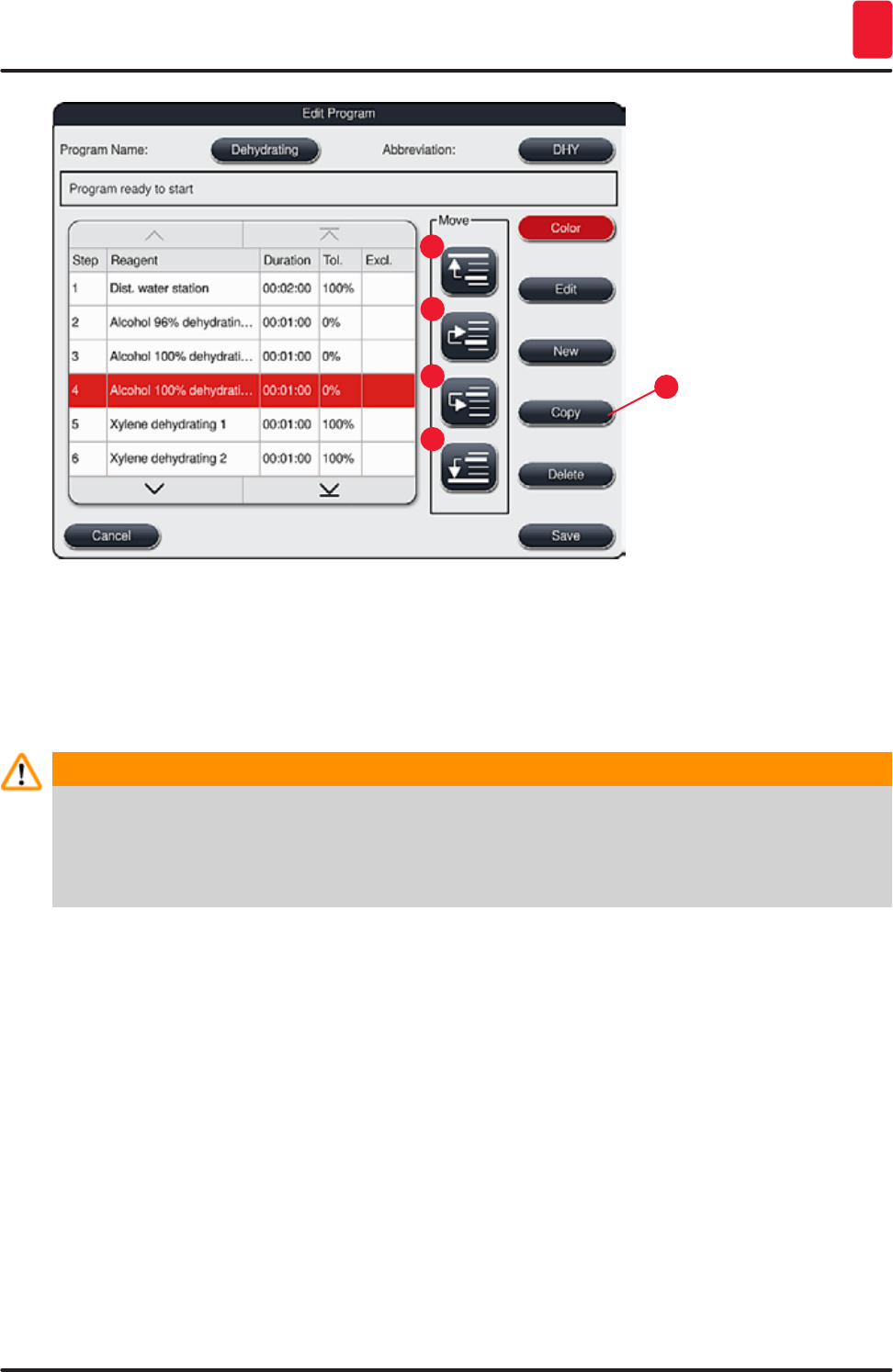
73
HistoCore SPECTRA ST
Operation 5
1
3
2
4
5
Fig. 49
1 Press to move the selected program step to the first row.
2 Press to move the selected program step one row up.
3 Press to move the selected program step one row down.
4 Press to move the selected program step to the last row.
Warning
If an oven step is used as the first program step, a flammable solvent must not be present in the
loading station of the input drawer under any circumstances.
This may cause a ignition in the oven, which can cause the operator to be burned, specimen loss
and damage to the instrument and equipment.
• The "Save" button (→ "Fig. 49") is used to apply the changes. Press the "ESC" button to discard the
entry.
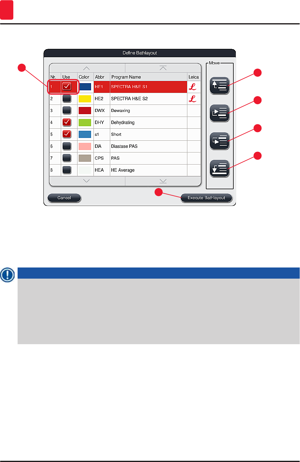
74 Version 1.3, Revision J
Operation
5
5.9.8 Prioritizing programs for creating the bathlayout
1
5
3
2
6
4
Fig. 50
After all desired staining programs have been entered, the bathlayout has to be generated. To do so,
proceed as follows:
• In the first step, the supervisor should define which programs are to be taken into the bathlayout. The
programs are activated via the radio button(s) (→ "Fig. 50-1").
• The position of the program determines its priority for integration into the bathlayout.
Note
Priority:
• Only the positions of the user-defined programs can be moved. Leica staining programs are
always listed at the upper positions of the reagent list.
• The user-defined programs with low position numbers are easier to take into account when
creating the bathlayout than programs with high position numbers.
• We recommend positioning user-defined programs with high specimen throughput at the
beginning of the program list, following the Leica staining programs.
If a higher or lower priority is to be assigned to a staining program, select it in the list and move it higher
or lower in the list using the "Move" buttons:
- Program is moved to the first row (→ "Fig. 50-2")
- Program is moved up one row (→ "Fig. 50-3")
- Program is moved down one row (→ "Fig. 50-4")
- Program is moved to the last row (→ "Fig. 50-5")
• Due to the new priorities, the bathlayout must be recreated (→ p. 75 – 5.9.9 Creating the
bathlayout).
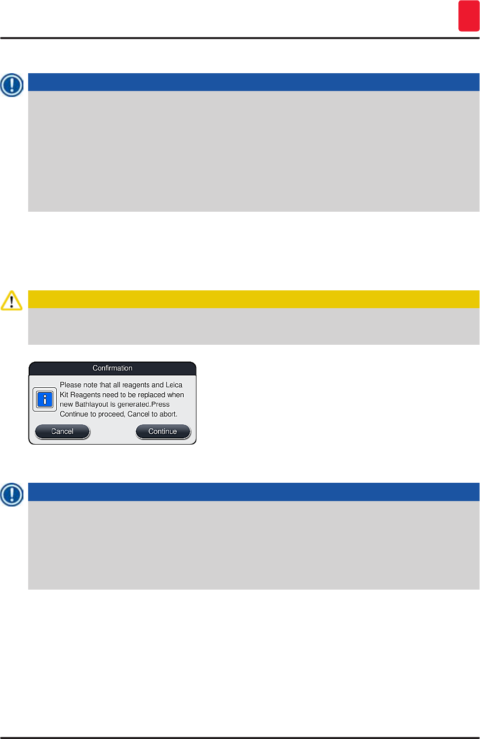
75
HistoCore SPECTRA ST
Operation 5
5.9.9 Creating the bathlayout
Note
The arrangement of the reagent stations in the instrument is calculated using the prioritized staining
programs (→ p. 74 – 5.9.8 Prioritizing programs for creating the bathlayout).
These are some things to be observed when doing so:
• Leica staining programs are taken into account first,
• Staining and differentiation solutions are placed as close as possible to the rinsing water
vessels,
• The program prioritization and process class assignment are observed,
• Sequential process reagents must be located close to each other.
• To select the programs that are to be integrated into the bathlayout, push the "Define Bathlayout"
(→ "Fig. 45-3") button.
• Select and prioritize the respective programs, then press the "Execute Bathlayout" (→ "Fig. 50-6")
button or "Cancel" to return to the program selection.
Caution
Be sure to observe the message (→ "Fig. 51") displayed after pressing the "Define bathlayout" button!
Press the "Continue" button in order to display the result of the calculation of the bathlayout.
Fig. 51
Note
• The user is informed if more programs have been selected than were able to be integrated
into the bathlayout by the display "Bathlayout Generation Result" (→ "Fig. 52"). Successfully
integrated programs are marked by a check mark in the "Ready" column (→ "Fig. 52-1").
• For programs that cannot be integrated the reason is specified in the "Not ready, Causes"
(→ "Fig. 52-2") (→ "Fig. 52-3") column.
• Note that the list must be inspected all the way through.
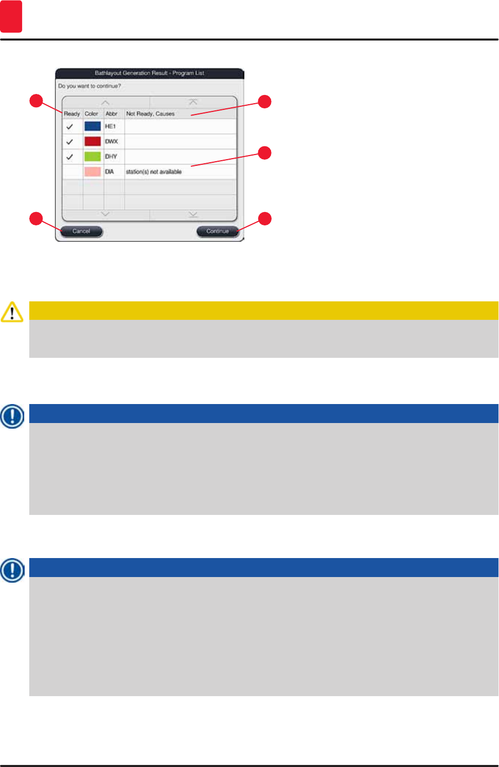
76 Version 1.3, Revision J
Operation
5
Fig. 52
1
3
2
4
5
• Press the "Continue" (→ "Fig. 52-4") button to proceed or the "Cancel" (→ "Fig. 52-5") button to return
to the program selection (→ "Fig. 50").
Caution
Additionally, the instructions for use provided with the Leica reagent kits must be observed before
filling in Leica reagents!
5.9.10 Filling reagents after bathlayout creation
Note
• Create the bathlayout and proceed as described (→ p. 75 – 5.9.9 Creating the bathlayout).
• If the bathlayout shown is only to be saved without configuring the reagent filling, press the
"Save" button (→ "Fig. 53-3"). The stored bathlayout can then be called up in the bathlayout menu.
If necessary, subsequent adjustments can be made in this menu (→ p. 82 – 5.9.11 Adapting a
bathlayout). Filling the reagent vessel can also be configured to take place at a desired point in
time using the bathlayout menu (→ p. 90 – 6.4 Station details).
• After the software calculates the bathlayout using the prioritized programs, the user obtains an
overview of the results displayed on the screen (→ "Fig. 53").
Note
• If no Leica programs were integrated into the bathlayout, the display (→ "Fig. 53") deviates from
the one shown (not pictured). In this case, the reagents can be filled as described in (→ p. 78 –
Filling the reagents).
• If Leica programs were integrated into the bathlayout, the reagent "95 % Alcohol Dehyd 1" must
first be duplicated. The station in question in the bathlayout is identified with a blue outline
(→ "Fig. 53-1").
• The reagent "95 % Alcohol Dehyd 1" to be duplicated is displayed with the abbreviation "95Dhy1"
in the bathlayout.
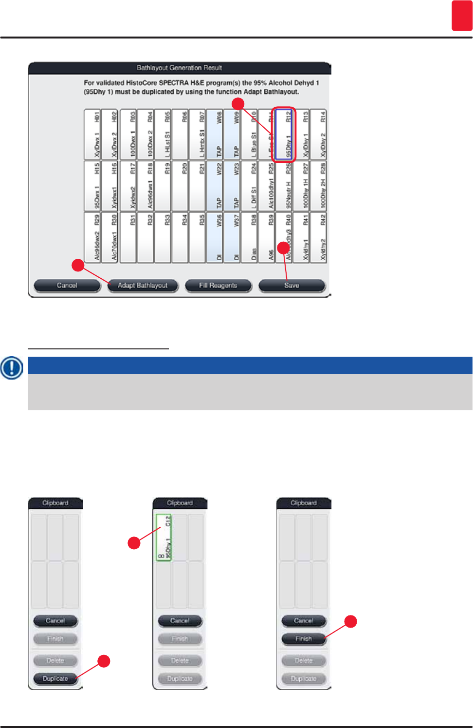
77
HistoCore SPECTRA ST
Operation 5
Fig. 53
1
2
3
Duplicating the reagent "95Dhy1"
Note
If there is no reagent station available due to the selected programs, attempt to optimize user-
defined programs using the Leica sales organization.
The procedure for duplicating the reagent "95Dhy1" is as follows:
1. Press the "Adapt Bathlayout" (→ "Fig. 53-2") button.
2. Note the subsequent message and confirm it with "Ok". A new "Clipboard" (→ "Fig. 54")
window opens.
1
3
2
Fig. 54
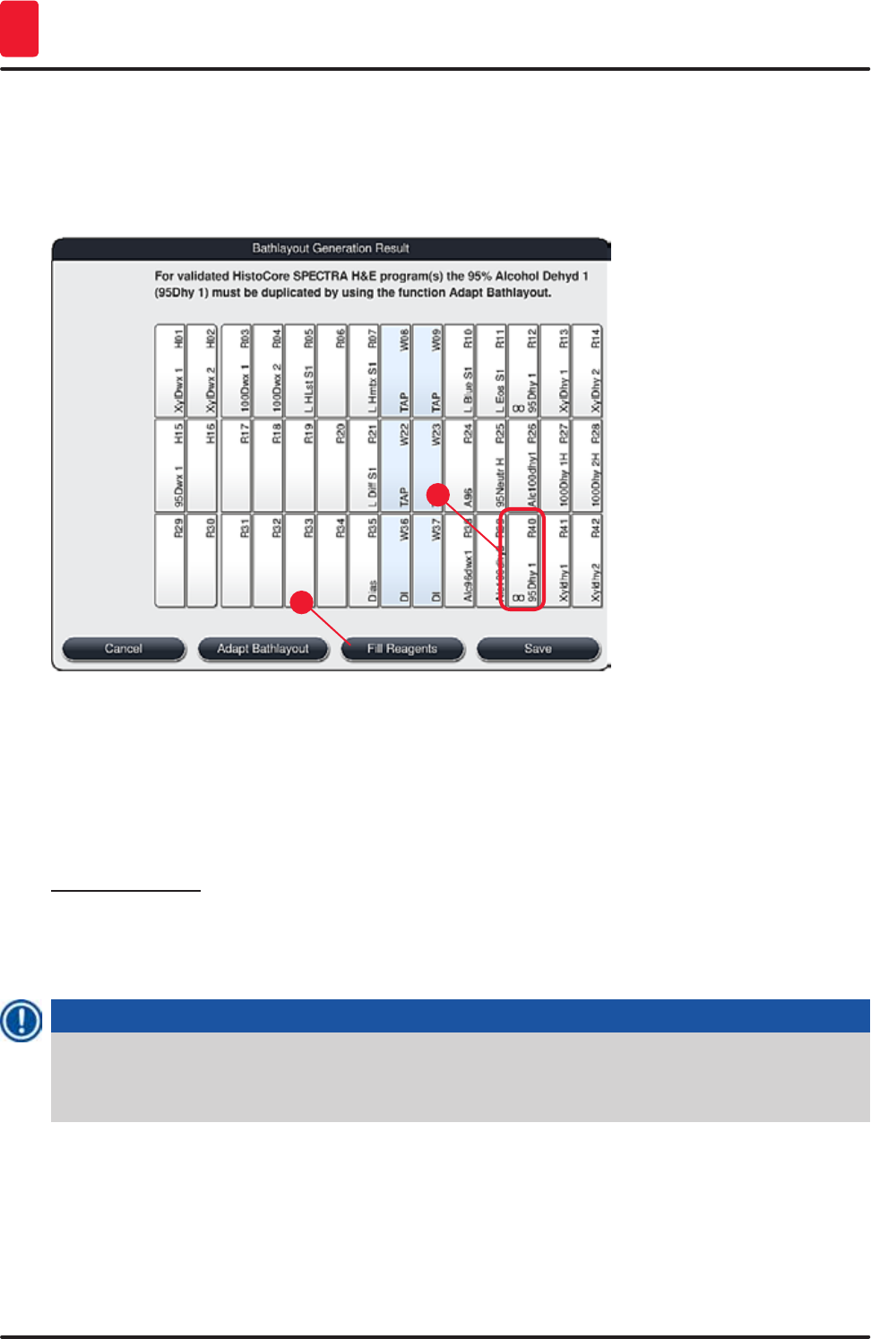
78 Version 1.3, Revision J
Operation
5
3. Select the station "95Dhy1" (→ "Fig. 53-1") in the bathlayout by tapping it (station is marked
in green) and click on the "Duplicate" (→ "Fig. 54-1") button in the "Clipboard" window. An
identical copy of the selected station is now displayed in the "Clipboard" (→ "Fig. 54-2").
4. Select the station in the "Clipboard" and then click on a free position in the "Bathlayout". The
duplicated station is moved from the clipboard to the bathlayout (→ "Fig. 55-1").
1
2
Fig. 55
5. Press the "Finish" button (→ "Fig. 54-3") in the "Clipboard" and confirm the subsequent
message with "Yes" in order to apply the change and close the clipboard.
The successfully duplicated station "95Dhy1" and the original station are displayed with an
equivalence symbol (∞) in the bathlayout (→ "Fig. 55-1").
Filling the reagents
1. Press the "Fill reagents" button (→ "Fig. 55-2").
2. In the new "Fill reagents" (→ "Fig. 56") window, the stations to be filled are marked in orange
(→ "Fig. 56-1").
Note
Only user-defined and added reagents of Leica staining programs are displayed with an orange
marking (→ "Fig. 56"). The reagents from the Leica reagent kit are subsequently fed in (→ p. 79 –
Filling the Leica reagent kit reagents).
3. Fill the marked reagent vessels outside of the instrument with the corresponding reagents in
sequence and set them back in the correct position in the instrument.
4. Confirm filling and resetting the reagent vessels by pressing the respective station
(→ "Fig. 56-1") on the screen.
5. Repeat these steps for all stations marked in orange.
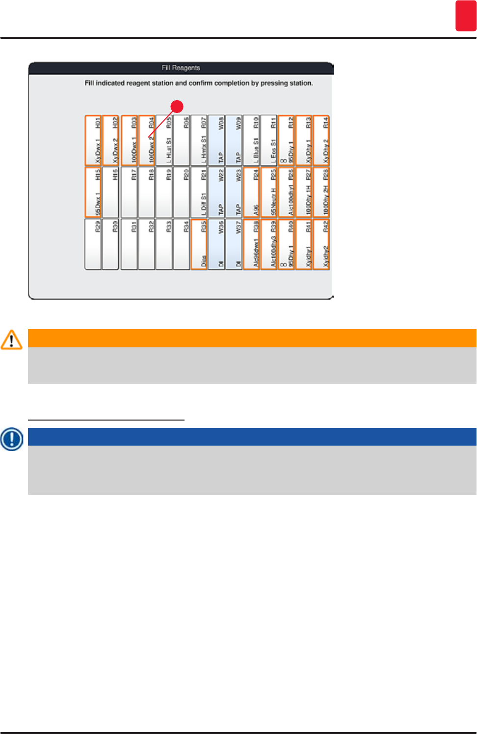
79
HistoCore SPECTRA ST
Operation 5
1
Fig. 56
Warning
The arrangement of the assignment plan is to be followed exactly. Any deviation can lead to
undesired staining results.
Filling the Leica reagent kit reagents
Note
After duplicating the reagent station "95 % Alcohol Dehyd1" (→ p. 77 – Duplicating the reagent
"95Dhy1") and filling the reagents (→ p. 78 – Filling the reagents), the Leica kit reagents are
subsequently fed in.
1. When prompted by an information message (→ "Fig. 57") on the screen, stop the carton's
packaging label in front of the RFID sensor on the front of the instrument (→ "Fig. 58-1") to scan
it.
2. Then, begin to scan in the first Leica reagent bottle after being prompted by a message
(→ "Fig. 58-2"). Hold the reagent bottle label in front of the RFID sensor on the front of the
instrument (→ "Fig. 58-1") in order for it to be scanned.
3. In the new window "Change Leica kit reagent" (→ "Fig. 59"), the station to be filled is marked in
orange (→ "Fig. 59-1").
4. Fill the marked reagent vessel outside of the instrument with the corresponding reagent and
set it back in the correct position in the instrument.
5. Confirm filling and resetting the reagent vessel by pressing the respective station
(→ "Fig. 59-1") on the screen.
6. Then, scan the labels of the individual reagent bottles when prompted (→ "Fig. 58-2") and
repeat steps 2-5.
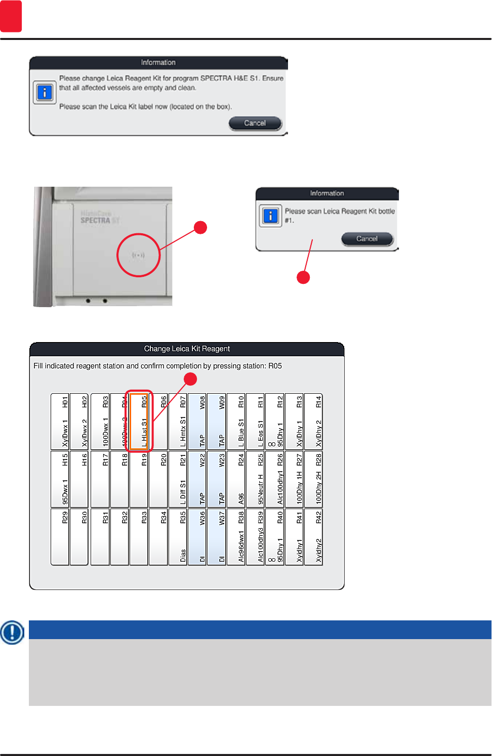
80 Version 1.3, Revision J
Operation
5
Fig. 57
1
2
Fig. 58
1
Fig. 59
Note
The user has 5 minutes to scan the reagents for the carton's packaging label and 5 minutes per
reagent bottle.
If reading in a reagent bottle or packaging label fails, the user has 2 additional attempts before the
reagent labels become invalid.
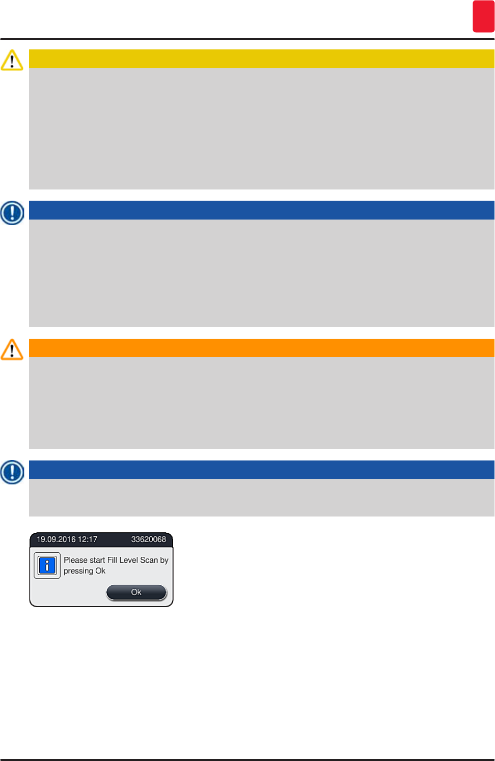
81
HistoCore SPECTRA ST
Operation 5
Caution
Each Leica reagent kit can only be scanned once!
• Scanning in the Leica reagent kit can only be canceled by using the "Cancel" button in the
message shown in (→ "Fig. 57") and before starting to read in the package label without the
Leica reagent kit expiring.
• The scanning can be configured later. More information necessary for this procedure is
described in (→ p. 95 – Reagent replacement) (→ "Fig. 76") and (→ "Fig. 77").
• If the operation is not canceled until after reading in the first label (packaging cardboard), the
Leica reagent kit expires.
Note
The reagent management system (RMS) automatically takes over the following data for the Leica
reagents:
• The use-by date (once opened)
• The remaining number of specimen slides
• The max. number of specimen slides
• The expiration date
• The batch number
Warning
• The arrangement of the bathlayout is to be followed exactly. Any deviation can lead to undesired
staining results.
• All of the Leica reagent kit bottles are to be scanned.
• Make sure that no Leica reagents from different Leica reagent kits are used.
• Reagent vessels must always be filled outside of the instrument in compliance with the safety
information.
Note
The user is finally prompted by a message on the screen to start the automatic fill level scan. Press
"OK" in the message (→ "Fig. 60") to start the scan.
Fig. 60
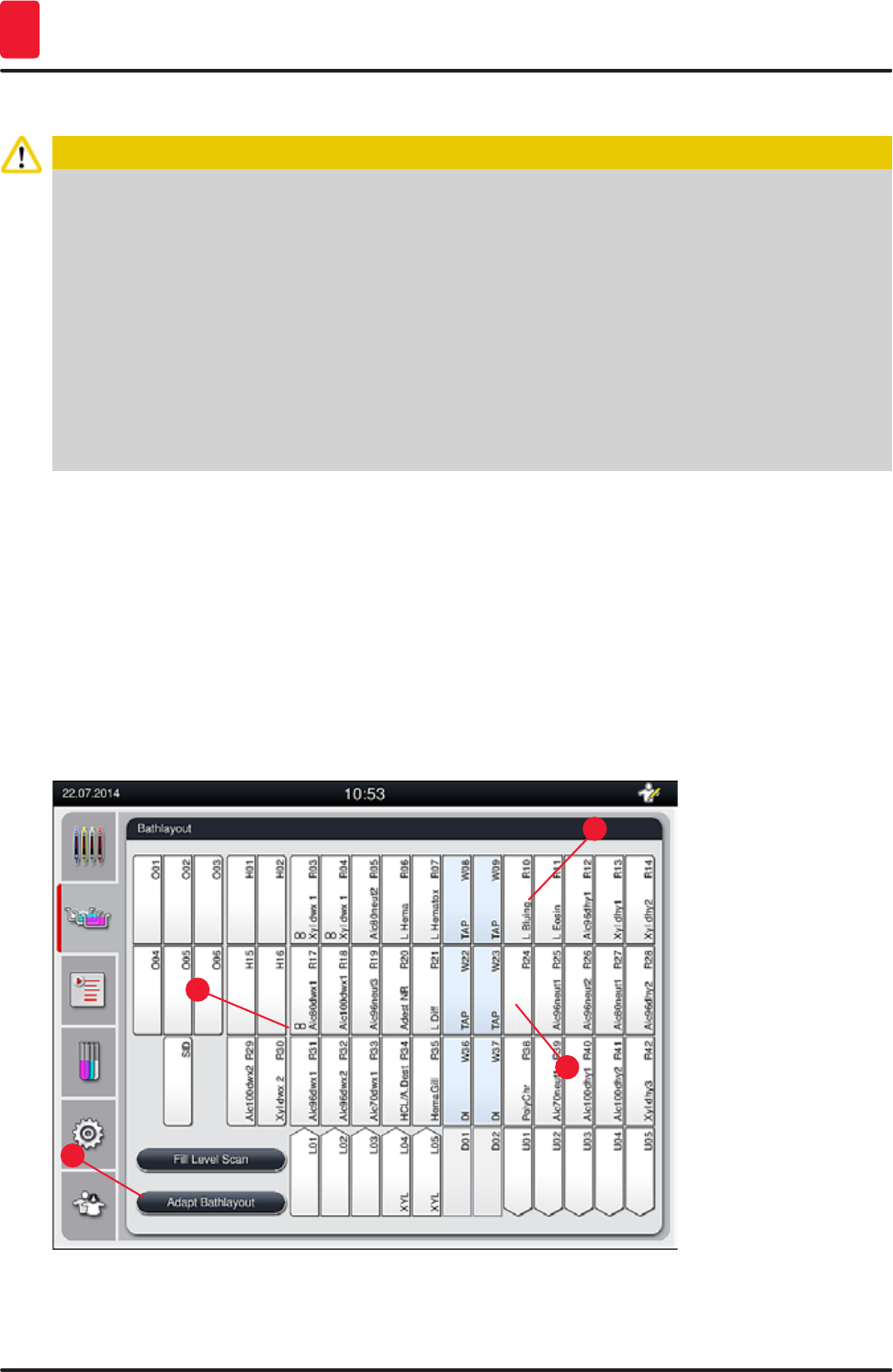
82 Version 1.3, Revision J
Operation
5
5.9.11 Adapting a bathlayout
Caution
The automatically and optimally created bathlayout should be adjusted only if special user
requirements were not taken into account or if this is required by a Leica program. For this reason,
the instructions for use provided with the Leica reagent kits must be observed! Supervisor mode is
needed to adjust the bathlayout.
Each adjustment of the bathlayout can have a negative effect on the specimen throughput and
staining result!
The following rules must be observed when adjusting the bathlayout:
• Reagent stations must not be moved from one side of the vessel field to the other because this
causes unnecessarily long transfer times.
• Duplicate stations have to be on the same side of the vessel field (→ "Fig. 40") (→ "Fig. 65"),
otherwise the adjustment to the bath layout cannot be saved.
If you need to adjust the bathlayout created by the HistoCore SPECTRA ST, which takes into account all
rules for optimization, this can be done by means of the function "Adapt Bathlayout" (→ "Fig. 61-1").
Using this function, station placements can be moved to their positions within the bathlayout and/or
duplicated.
To do so, proceed as follows:
• In the bathlayout view (→ "Fig. 61"), press the "Adapt Bathlayout" button (→ "Fig. 61-1").
• Observe the messages that follow (→ "Fig. 62") (→ "Fig. 63") and confirm them or press "Cancel"
(→ "Fig. 63") to return to the bathlayout view.
• After confirmation, the "Clipboard" (→ "Fig. 64") will open, to which up to 6 reagent stations
(→ "Fig. 64-1") can be moved.
1
3
2
4
Fig. 61
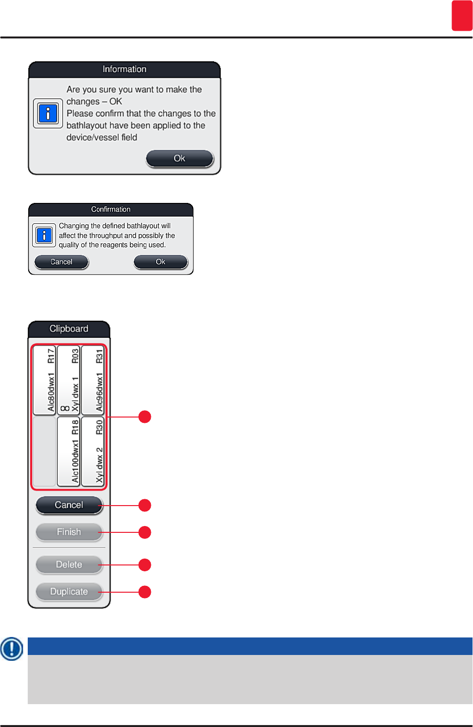

84 Version 1.3, Revision J
Operation
5
Note
• The clipboard can be closed only if no more reagent stations are in it.
• A message on the screen prompts the user to start the automatic fill level scan after each change
made using the "Adapt Bathlayout" function. Press "OK" in the message to start the scan.
There are two options for changing the bathlayout:
Moving reagent stations:
1. To move reagent stations, select them individually in the bathlayout (→ "Fig. 61") by touching
the screen and then tapping an available position in the clipboard (→ "Fig. 64-1").
2. This moves the reagent station to the clipboard (→ "Fig. 64-1").
3. Finally, select the reagent station in the clipboard by tapping and dragging it to the desired
(available) station (→ "Fig. 61-2") in the bathlayout.
4. To save your changes, press the "Finish" (→ "Fig. 64-3") button and confirm the subsequent
message with a "Yes" or "No" to return to the clipboard.
5. To delete the changes, press "Cancel" (→ "Fig. 64-2") and answer the subsequent message
with a "Yes".
Duplicate a reagent station
1. To duplicate a reagent station, select it in the bathlayout by touching the screen.
2. Subsequently press the "Duplicate" (→ "Fig. 64-5") button.
3. As a result, the reagent station appears in the clipboard. This station and the original station
are displayed with an equivalence symbol (→ "Fig. 61-4").
4. After this, select the duplicate reagent station in the clipboard by touching the screen and
place it in the desired (available) station, near the original station in the bathlayout.
5. To save your changes, press the "Finish" button and confirm the subsequent message with a
"Yes" or "No" to return to the clipboard.
6. To delete the changes, press "Cancel" and answer the subsequent message with a "Yes".
Note
• Duplicated reagent stations make sense for program steps with a long dwell time in a reagent.
Duplicated stations make two equivalent reagent stations available for a program step, which
ensures getting a high specimen throughput.
• Duplicated reagent stations can be deleted using the "Delete" button (→ "Fig. 64-4"). To do so,
mark them in the bathlayout by touching them and pressing the "Delete" button.
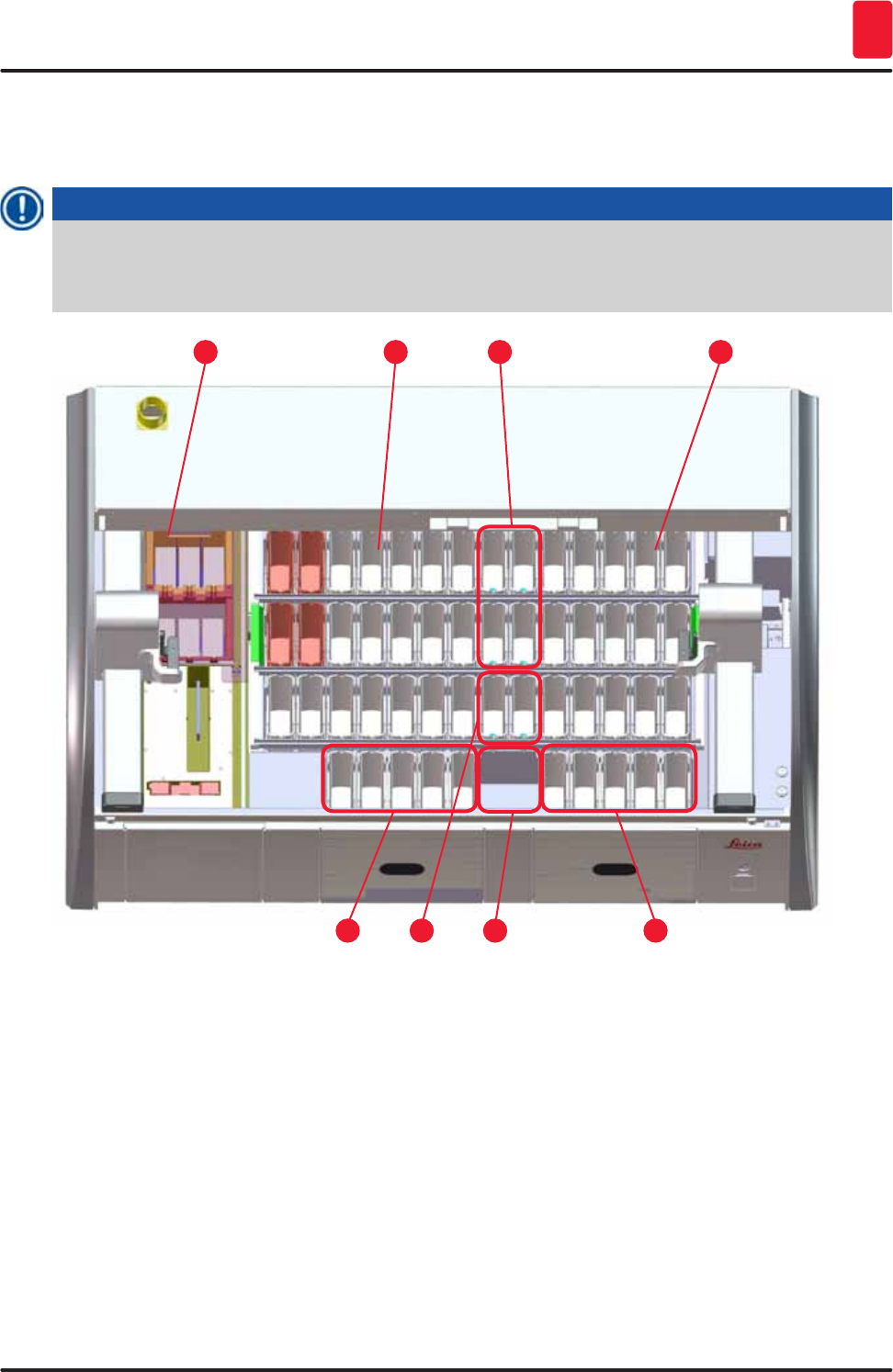
85
HistoCore SPECTRA ST
Daily instrument setup 6
6. Daily instrument setup
6.1 Preparing the instrument for daily setup
Note
• (→ "Fig. 65") shows an overview of the various stations in the vessel field.
• Altogether, the vessel field consists of 36 reagent stations and 6 rinsing water stations.
• The max. capacity of each reagent vessel is 380 ml.
153
7 6
4
8
9
Fig. 65
1 6 oven stations
3 Left vessel field
4 Rinsing water stations (group of four)
5 Right vessel field
6 5 unloading stations
7 Dry transfer station
8 Rinsing water stations (group of two)
9 5 loading stations
86 Version 1.3, Revision J
Daily instrument setup
6
6.2 Daily instrument setup
Note
Before setting up the instrument every day, check the water inlet to the instrument and turn it on if
necessary.
• Open the instrument hood and remove the covers from the reagent vessels.
• Switch on the instrument.
Automatic fill level scan when initializing the instrument
During the initialization, fill level scans are automatically carried out in the following areas:
• Reagent vessels
• Rinsing water vessels
• Reagent vessels of the loading and unloading stations
• Oven station
Note
If the instrument still contains racks, reagent vessels that are insufficiently filled or still covered,
and/or rinsing water vessels that are not ready for use, this is detected during the automatic fill
level scan and displayed when finished.
6.2.1 Preparation and handling of reagent vessels
To ensure that everything runs smoothly in the instrument, observe the following notes and proceed as
follows.
Attaching the reagent vessel handle
Check whether the reagent vessel handle is correctly attached to the reagent vessel. If this is not the
case, fasten the handle according to (→ "Fig. 66").
Filling and draining reagent vessels
Warning
The reagent vessels are always to be filled or drained outside of the instrument to avoid or reduce
the risk of spilling reagents into other reagent vessels and onto interior instrument components.
Proceed carefully when filling or draining the reagent vessels and follow the respectively
applicable laboratory specifications. If reagents were spilled or another reagent station has been
contaminated, it must be cleaned and re-filled. The vessels must be covered when not using the
instrument to prevent the unnecessary evaporation of the reagents.
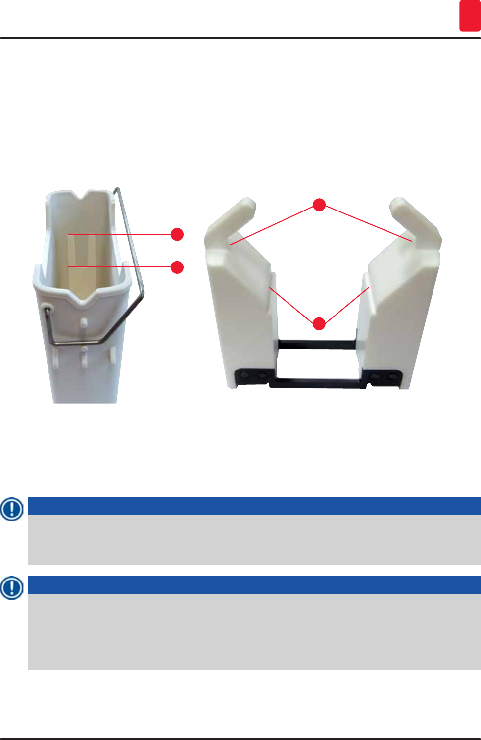
87
HistoCore SPECTRA ST
Daily instrument setup 6
Correct fill level of the reagent vessels
• When filling either reagent vessel type, observe the fill level marks inside the reagent vessels
(→ "Fig. 66") (→ "Fig. 67").
• A sufficient filling level is ensured if the level of the reagents is between the maximum (→ "Fig. 66-1")
and minimum (→ "Fig. 66-2") fill level marks.
• If inserts for special dyes (→ "Fig. 67") are used in the reagent vessels in order to reduce reagent
volume, insert these into the reagent vessel first and then fill the reagent at least up to the minimum
filling level indicated (→ "Fig. 67-2"), but not over the maximum filling level (→ "Fig. 67-1").
1
2
Fig. 66
1
2
Fig. 67
Inserting the reagent vessel into the vessel field
• Select "Bathlayout" (→ p. 38 – 5.5 Main menu - overview) in the main menu and insert the reagent
vessel into the correct position according to the arrangement of the bathlayout.
Note
Carefully insert the reagent vessel with handle into the vessel field so that the handle is on the right
side of the reagent vessel when looking at the vessel field (→ "Fig. 68-1"). This orientation of the
handle is recommended also for placing the reagent vessels in the loading or unloading station .
Note
A special coating is also applied when using special dyes (as with the rack handle for 5 slides)
which prevents chemical interactions with reagents for special applications (e.g. Prussian blue
staining for iron detection, silver stains such as Grocott or Gomori). For more information about
reagents that should be used with coated accessories, see (→ p. 144 – Appendix 1 - Compatible
reagents).
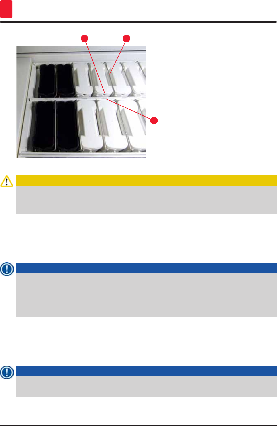
88 Version 1.3, Revision J
Daily instrument setup
6
1
3
2
Fig. 68
Caution
Do not insert the reagent vessels into the instrument laterally offset from the station number. To do
so, make sure that the notch on the front side of the reagent vessel (→ "Fig. 68-2") and the station
number (→ "Fig. 68-3") are at the same height.
6.2.2 Automatic fill level scan
After filling and inserting the reagent vessels, the automatic fill level scan (→ "Fig. 69-1") should be
carried out for verifying that all reagents used have the correct fill level.
Note
• The load and unload stations are not taken into account when creating the bathlayout. Reagents
in the load and unload stations have to be defined and monitored by the user.
• The reagents in the loading and unloading stations are not monitored by the reagent
management system. Therefore the user is responsible for making sure the reagents in these
stations are in flawless condition.
To start the fill level scan manually, proceed as follows:
1. Call up the "Bathlayout" (→ p. 38 – 5.5 Main menu - overview) in the main menu.
2. The "Fill Level Scan" (→ "Fig. 69-1") button is in the lower part of the menu screen.
3. Press this button to start the fill level scan.
Note
Irregularities during the fill level scan are displayed on the screen. Follow the information
messages and, for example, correct the fill level, remove the cover, add reagent vessels, etc.
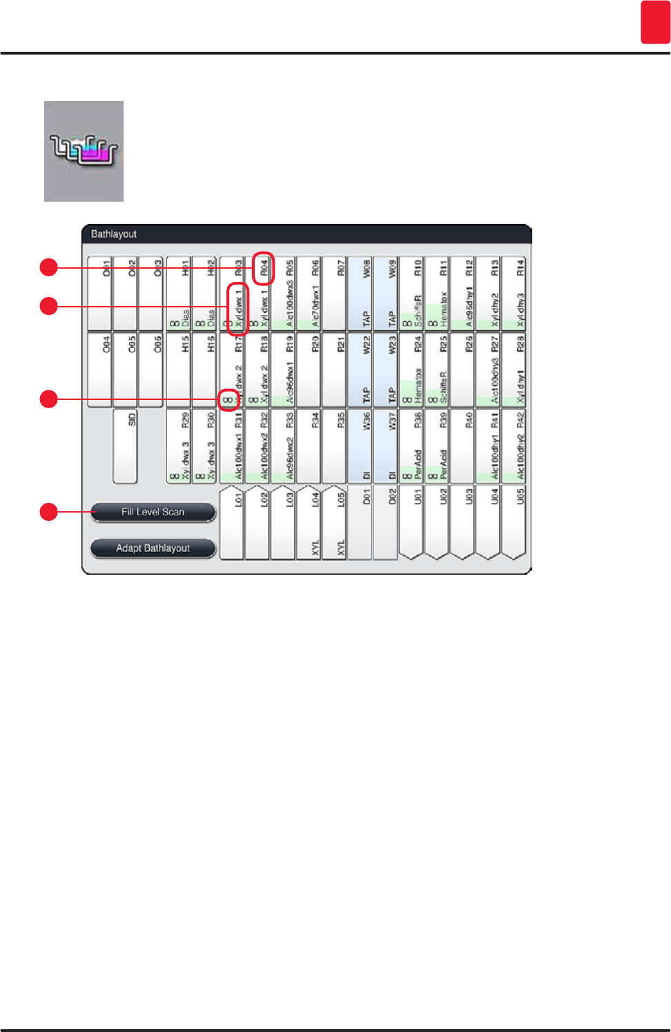
89
HistoCore SPECTRA ST
Daily instrument setup 6
6.3 Reagent management system (RMS)
The bathlayout (→ "Fig. 69") in the instrument is displayed by pressing the adjacent
menu button. This display shows the current layout of the reagent stations, the
rinsing water stations and the loading and unloading stations in the instrument.
Fig. 69
1
3
2
4
The bathlayout is empty when the instrument is delivered, because reagents still have not been defined
and a bathlayout has not yet been created.
If reagents (→ p. 59 – Creating a new reagent or copying a reagent) and programs (→ p. 69 –
5.9.5 Creating or copying a new staining program) have been defined and the bathlayout has been
created (→ p. 75 – 5.9.9 Creating the bathlayout), the overview (→ "Fig. 69") shows all stations in the
instrument in their real order.
Each reagent vessel shown in the bathlayout contains additional information:
• Station number (→ "Fig. 69-2")
• Abbreviating the reagent name (→ "Fig. 69-3")
• A background color (→ "Fig. 70")
• Equivalence symbol for a duplicated reagent station (→ "Fig. 69-4")
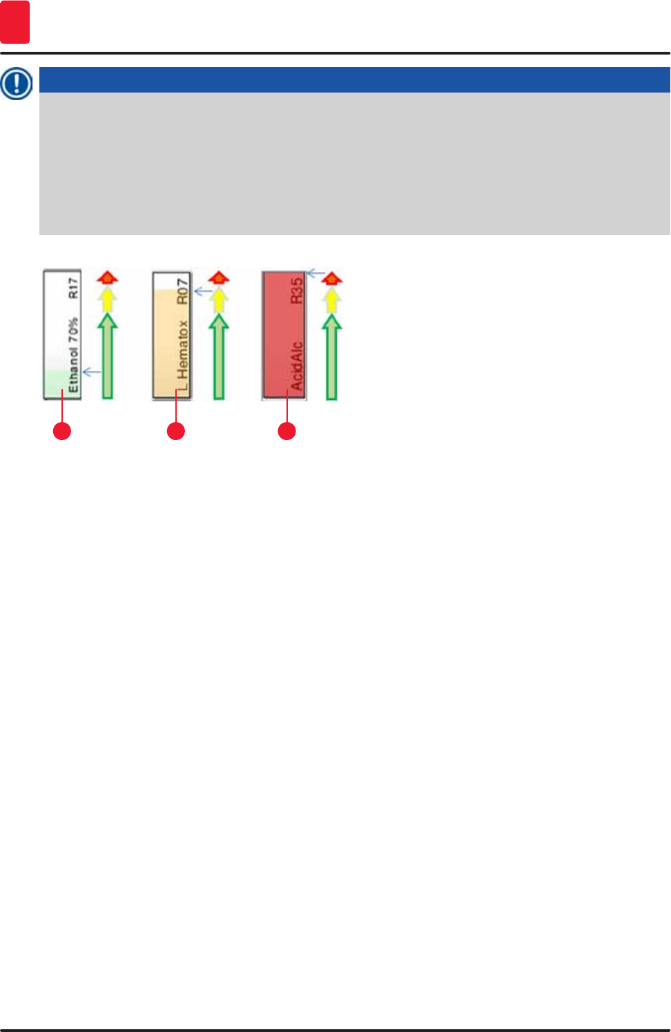
90 Version 1.3, Revision J
Daily instrument setup
6
Note
• The background color shows the consumption status of the reagent (→ "Fig. 70"). As the reagent
is consumed, the color bar rises from the bottom to the top and changes color based on the
consumption status.
• As soon as the "Red" (→ "Fig. 70-3") consumption status has been reached, and absolutely no
later than when the station flashes red, the reagent in question has to be replaced. If this is not
done, Leica staining programs are no longer able to start.
• For further information on the RMS, see (→ p. 56 – 5.8 Reagent list).
132
Fig. 70
1 Green: Consumption status between 0-80 % of the maximum use limit
2 Yellow: Consumption status between 80-95 % of the maximum use limit
3 Red: Consumption status between 95-100 % of the maximum use limit
6.4 Station details
Touching a station in the bathlayout will display more information (station details). The following station
types are distinguished by their abbreviation:
L01-L05 Load stations
SID Specimen slide reader station and title block identification (optional)
O01-O06 Oven stations for drying the specimen slides and starting to melt the paraffin
R01-R42 Reagent stations
W08-W09
W22-W23
Rinsing water stations (group of four)
W36-W37 Rinsing water stations (group of two)
D01-D02 Dry transfer stations
U01-U05 Unloading stations in the output drawer
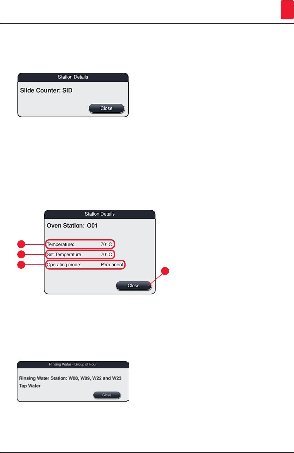
91
HistoCore SPECTRA ST
Daily instrument setup 6
Specimen slide reader station (SID):
Touching this station causes a note to appear indicating that this station is the specimen slide reader
station. The "Close" (→ "Fig. 71") button is used to close the display.
Fig. 71
Oven stations:
The detail view (→ "Fig. 72") of an oven station shows:
• The current temperature (→ "Fig. 72-1"),
• The target temperature adjustment (→ "Fig. 72-2") and
• The operating mode (→ "Fig. 72-3") of the 6 oven stations.
The "Close" (→ "Fig. 72-4") button is used to close the display.
Fig. 72
1
3
2
4
Rinsing water stations (group of four):
The detail view of a rinsing water station (→ "Fig. 73") shows all other rinsing water stations that are
connected to the same water circuit. The "Close" button is used to close the display.
Fig. 73
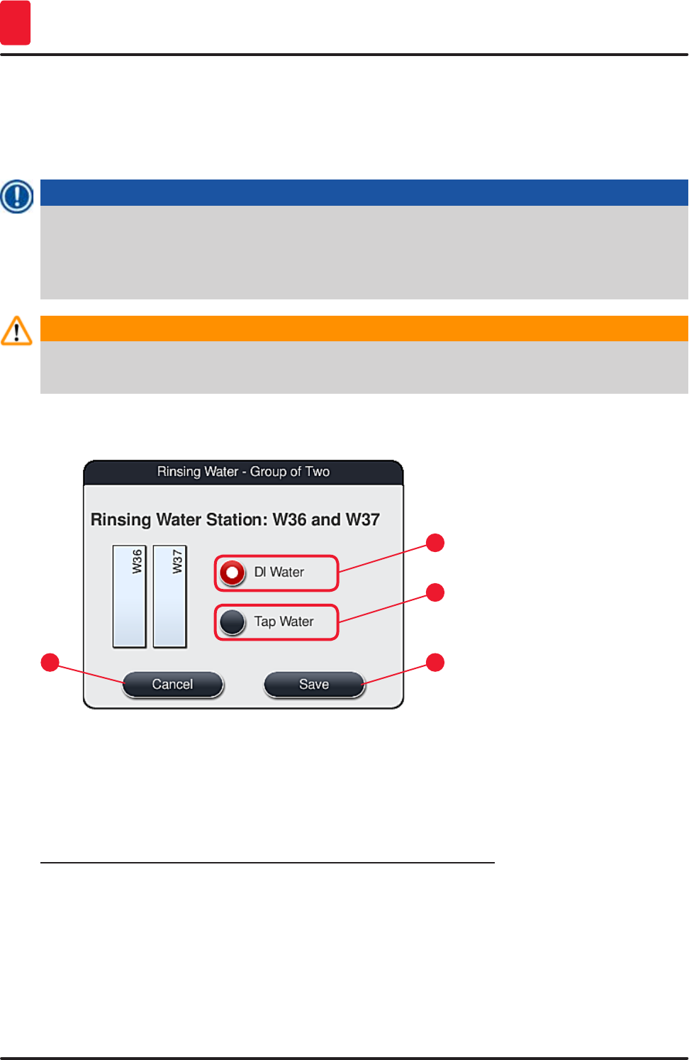
92 Version 1.3, Revision J
Daily instrument setup
6
Rinsing water stations (group of two):
When you tap a rinsing water station of a group of two, an information window opens that shows the
2 water stations, which are connected to the second water circuit with, for example, distilled water or
demineralized water (→ "Fig. 74-1") or rinsing water (→ "Fig. 74-2").
Note
Based on the connected supply (→ p. 26 – 4.2.1 Joint connection of all 6 rinsing water stations)
(→ p. 27 – 4.2.2 Combined connection 4+2 rinsing water stations), the corresponding selection
must be made in this menu.
The rinsing water stations (group of two) can only be programmed in supervisor mode.
Warning
The correct assignment and connection of the rinsing water vessels is absolutely necessary for
achieving good staining quality.
• To apply the settings, press the "Save"(→ "Fig. 74-3") button or press "Cancel" (→ "Fig. 74-4") to close
the display without applying potential changes.
1
3
2
4
Fig. 74
Loading stations in the input drawer
No reagents have been assigned yet to the loading stations in the factory condition of the instrument.
If a reagent is to be assigned to a loading station, run the following steps:
1. Select the corresponding station in the bathlayout (→ "Fig. 20-1") by touching it.
2. In the newly opened "Station Details" window, press the black "Reagent name" (→ "Fig. 75-1")
button to open the list of available reagents (→ p. 56 – 5.8 Reagent list).
3. Select the desired reagent by touching it and then hit "Apply".
4. To apply the settings, press the "Save" (→ "Fig. 75-2") button or press "Cancel" (→ "Fig. 16-3") to
close the display without applying potential changes.
The assigned reagent name is displayed in the bathlayout.
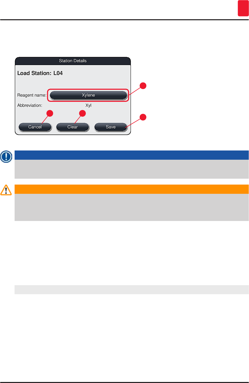
93
HistoCore SPECTRA ST
Daily instrument setup 6
If reagent is no longer required in the selected loading station, the assignment to the respective reagent
can be removed using the "Clear" (→ "Fig. 75-4") and "Save" (→ "Fig. 75-2") buttons in the "Station
details" window.
Fig. 75
1
32
4
Note
The load and unload stations are not taken into account when creating the bathlayout. Reagents in
the load and unload stations have to be defined and monitored by the user.
Warning
The racks are transported into any free unloading station at the end of a program. Therefore, all
unload stations must be filled with the same reagent.
The samples can potentially become damaged if this is not observed.
Reagent stations
An information window opens when the reagent station is touched. It displays additional relevant data
regarding the station type (reagent station (→ "Fig. 76"), Leica reagent station (→ "Fig. 77")).
Reagent name (→ "Fig. 76-1"),
Abbreviation (→ "Fig. 76-2")
(→ p. 60 – Creating a new reagent or copying a reagent)
Consumption status (→ "Fig. 76-3") (→ p. 89 – 6.3 Reagent management system (RMS))
Remaining slides (→ "Fig. 76-4"),
Slides max. (→ "Fig. 76-6")
Displays the number of remaining processable specimen
slides. When inserting a rack into the instrument, the slides
contained in it are counted by the specimen slide reader
station and subtracted from the number of remaining slides.
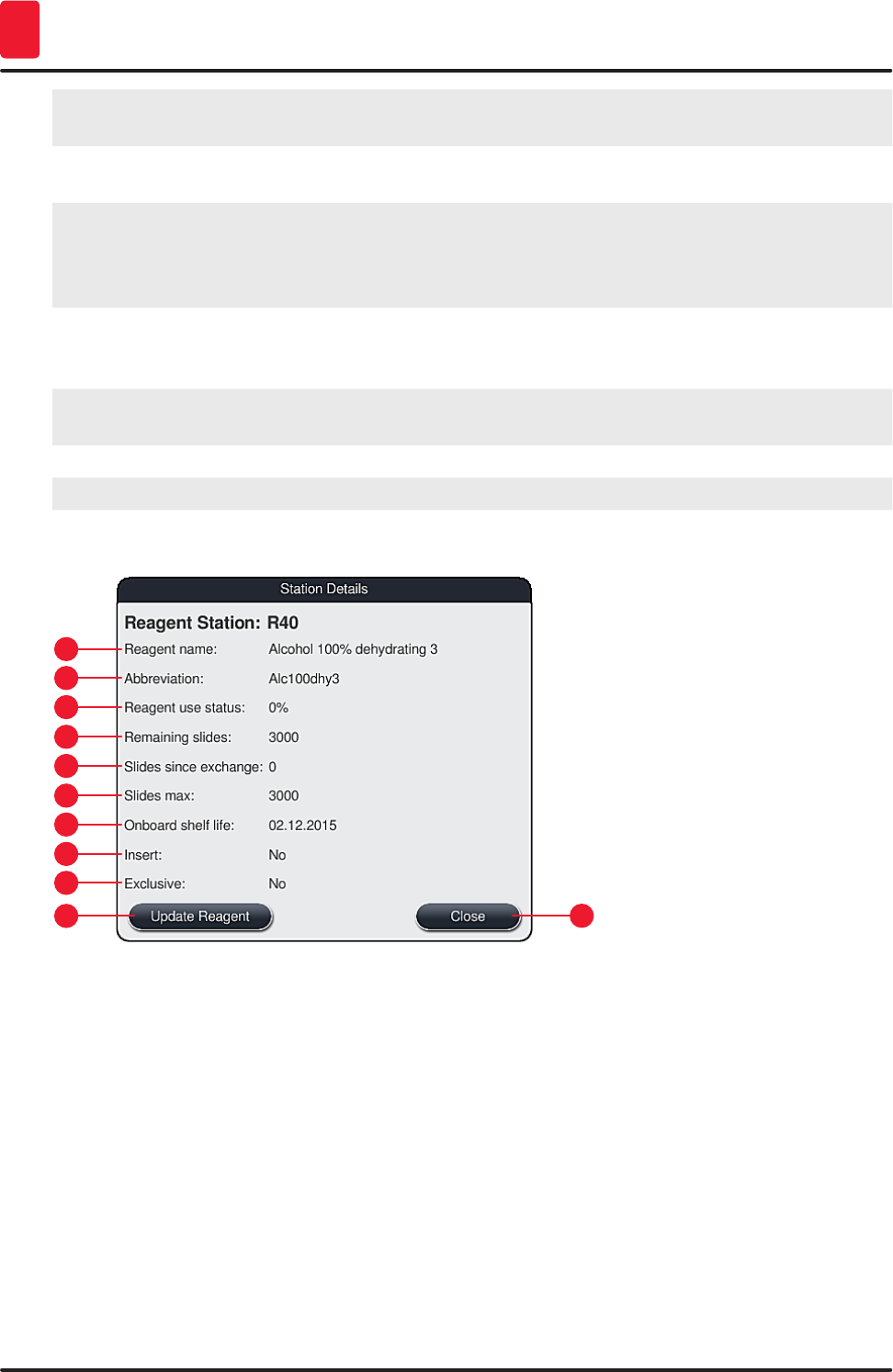
94 Version 1.3, Revision J
Daily instrument setup
6
Slides since exchange (→ "Fig. 76-5") Displays the number of specimen slides processed since the
last reagent changeover.
Onboard shelf life (→ "Fig. 76-7") Displays the shelf life of the reagent filled into the reagent
vessel.
Insert yes/no (→ "Fig. 76-8") "Yes" indicates that the insert for special dyes and the slide
holder for 5 slides is used. This station cannot be used for
programs with slide holders for 30 slides (→ p. 56 – 5.8
Reagent list).
Exclusive Yes/No (→ "Fig. 76-9") The setting "Yes" defines that the reagent is only assigned
to one program. "No" allows use by multiple programs
(→ p. 71 – 5.9.6 Inserting or copying a new program step).
Expiry date (→ "Fig. 77-1"), Lot number
(→ "Fig. 77-2")
is applied automatically when scanning the packaging of the
Leica reagent kit.
Detail view of reagent station
1
9
5
3
11
7
2
10
6
4
8
Fig. 76
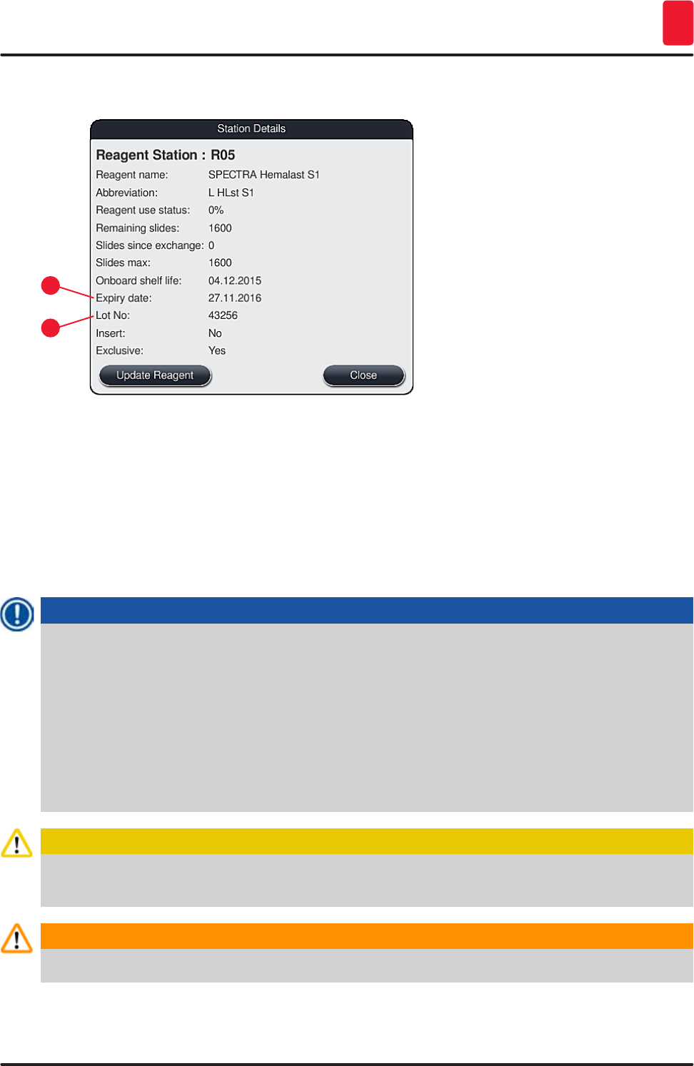
95
HistoCore SPECTRA ST
Daily instrument setup 6
Detail view of Leica reagent station
1
2
Fig. 77
Reagent replacement
• If the RMS indicates that a reagent is almost or completely consumed, a reagent change must occur.
This changeover must be confirmed by pushing the "Update Reagent" (→ "Fig. 76-10") button.
• When replacing the Leica reagents, first press the "Update Reagent" button and follow the
instructions for scanning and filling on the screen.
• The "Close" (→ "Fig. 76-11") button is used to close the display.
Note
• Please note: Replacement of reagents followed by an update to the RMS data is only possible
if the instrument is in an operational state and there are no longer any racks in the instrument
(including the input and output drawers).
If a user-defined staining program is still being used despite a required reagent changeover, the
number of specimen slides will exceed the "Maximum specimen slide" (→ "Fig. 76-6") value. The
exceeded number of specimen slides can be determined by comparing the information in the
"Slides since exchange" and "Slides max" rows in the station details (→ "Fig. 76-5").
• A limit of 30 excess specimen slides applies to reagents in Leica reagent kits. This limit does not
apply to additional reagents associated with the Leica program (e.g. alcohol, xylene).
Caution
Updating the reagent status without replacing the corresponding reagent will inevitably affect the
staining quality negatively.
Warning
NEVER press the "Update Reagent" button if the reagent has not been replaced.
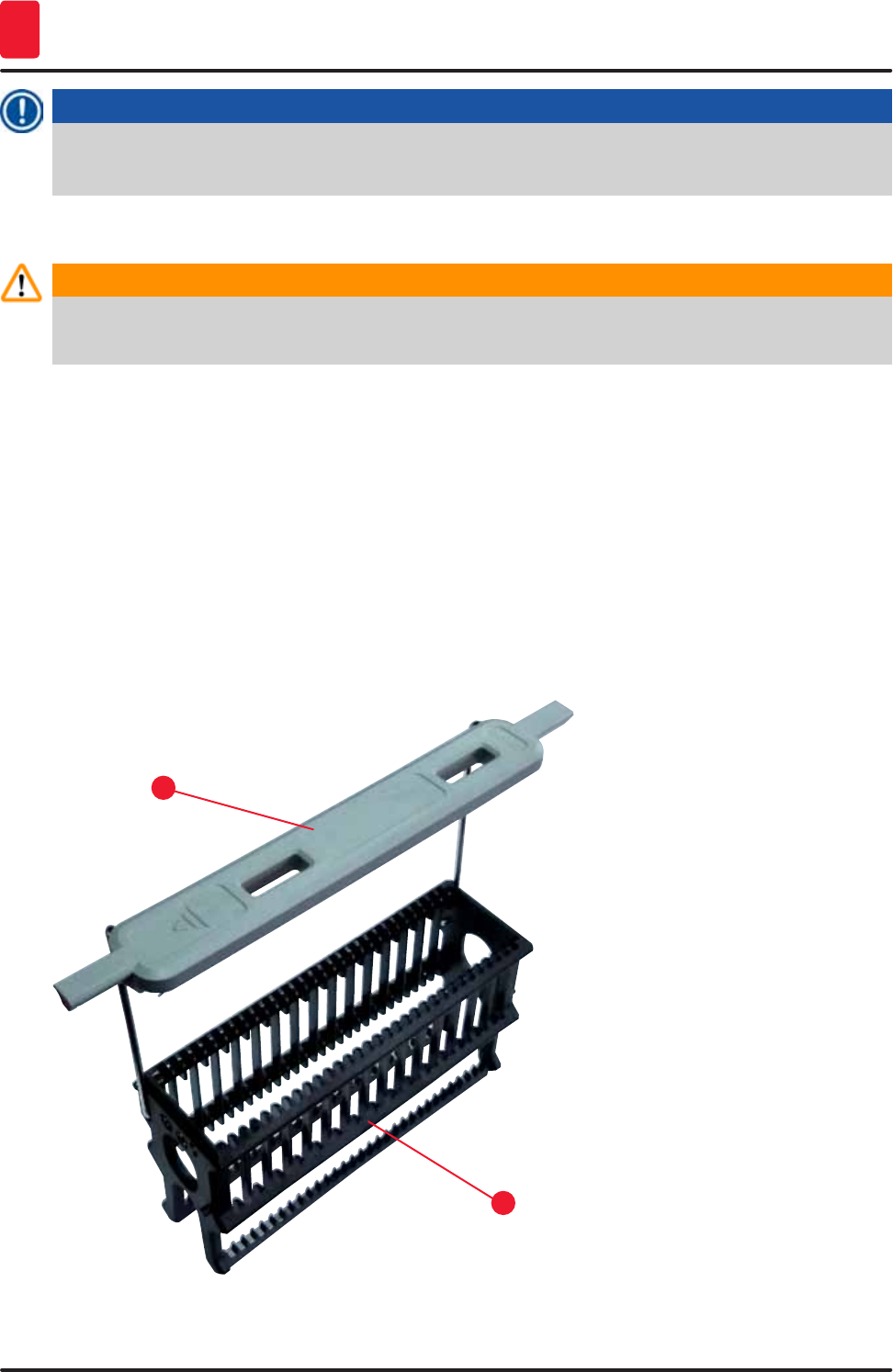
96 Version 1.3, Revision J
Daily instrument setup
6
Note
Each Leica reagent kit can only be scanned once!
Already added Leica reagents expire before their use-by date if a bathlayout is newly created.
6.5 Preparing the rack
Warning
Each rack handle (→ "Fig. 79-1") contains 2 RFID chips. Therefore, the rack handles may only be
attached to the rack (→ "Fig. 79-2") after a possible microwave step for specimen preparation.
Two different types of slide holders with compatible handles are available for use in the
HistoCore SPECTRA ST stainer:
• Rack for 30 specimen slides for routine staining (→ "Fig. 79").
• Rack for 5 specimen slides for special staining (→ "Fig. 80").
The colored handles must be correctly attached prior to using the rack in the instrument.
The rack handles must be attached corresponding to the previously defined program color
(→ p. 64 – 5.9.1 Assigning a rack handle color to a staining program).
The specimen slide handles are available in 9 colors (8 program colors & white) (→ p. 135 – 9.2
Optional accessories).
Fig. 79
1
2
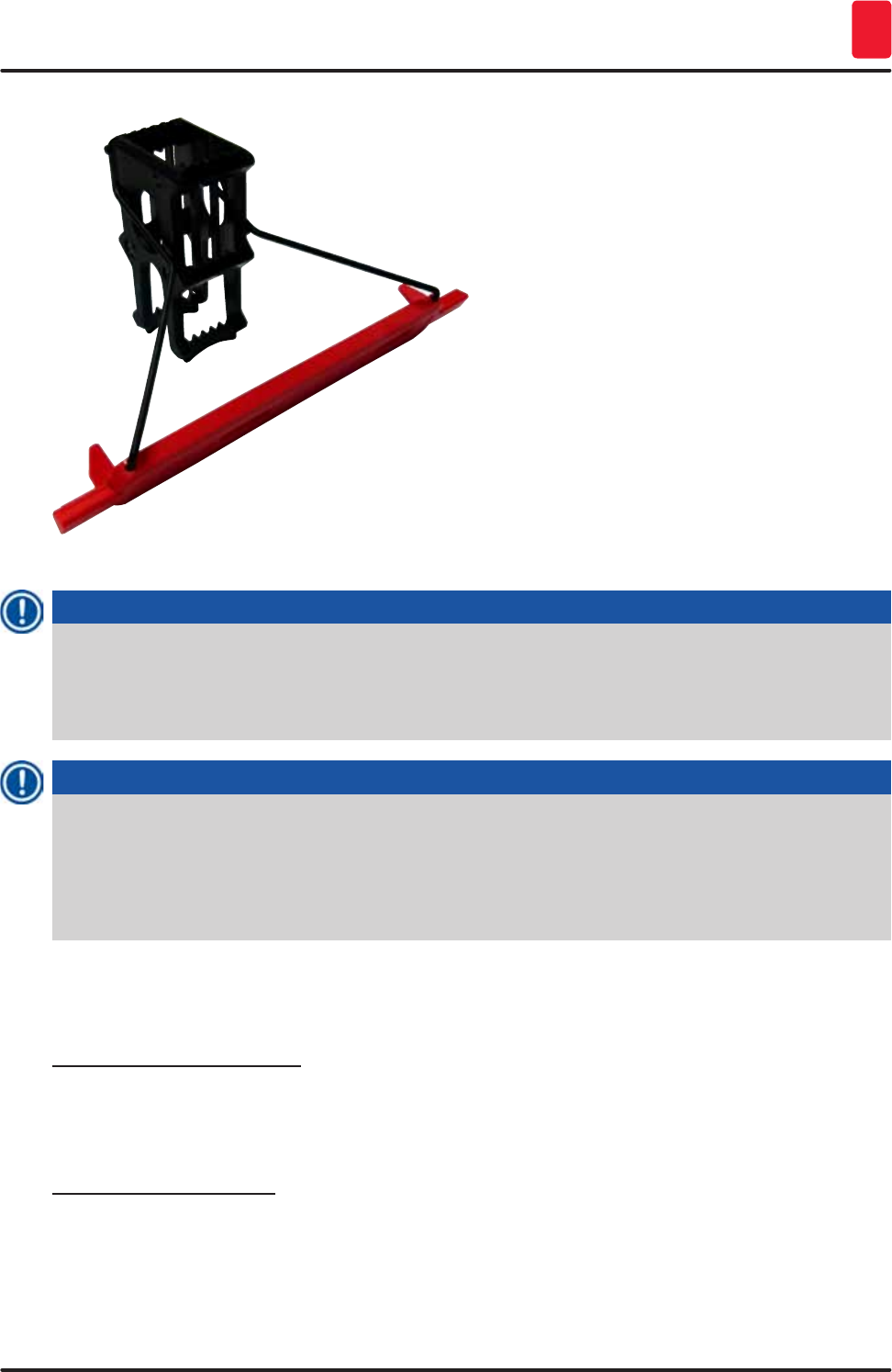
97
HistoCore SPECTRA ST
Daily instrument setup 6
Fig. 80
Note
The rack handle for 5 slides has a special coating, which prevents chemical interactions with
reagents for special applications (e.g. Prussian blue stain for iron detection, silver stains such
as Grocott or Gomori). For more information about reagents that should be used with coated
accessories, see (→ p. 144 – Appendix 1 - Compatible reagents).
Note
Special function of the white handle:
• The white handle cannot be permanently assigned to a staining program.
• Corresponding to a "wildcard function", the white handle has to be reassigned to a program
color each time the program is started.
• For this purpose, a selection menu opens on the screen automatically after inserting the rack.
Proceed as follows to attach or replace the rack handles:
Detach a handle from the rack:
• Slightly pull the handle apart (→ "Fig. 81"), so that the handle wire can be pulled out of the holes in the
rack.
Attach a handle to the rack:
• Slightly pull apart the handle and lift on the rack so that the handle wire snaps into the respective
holes on the left and right in the rack (→ "Fig. 81-1") (→ "Fig. 81-2").
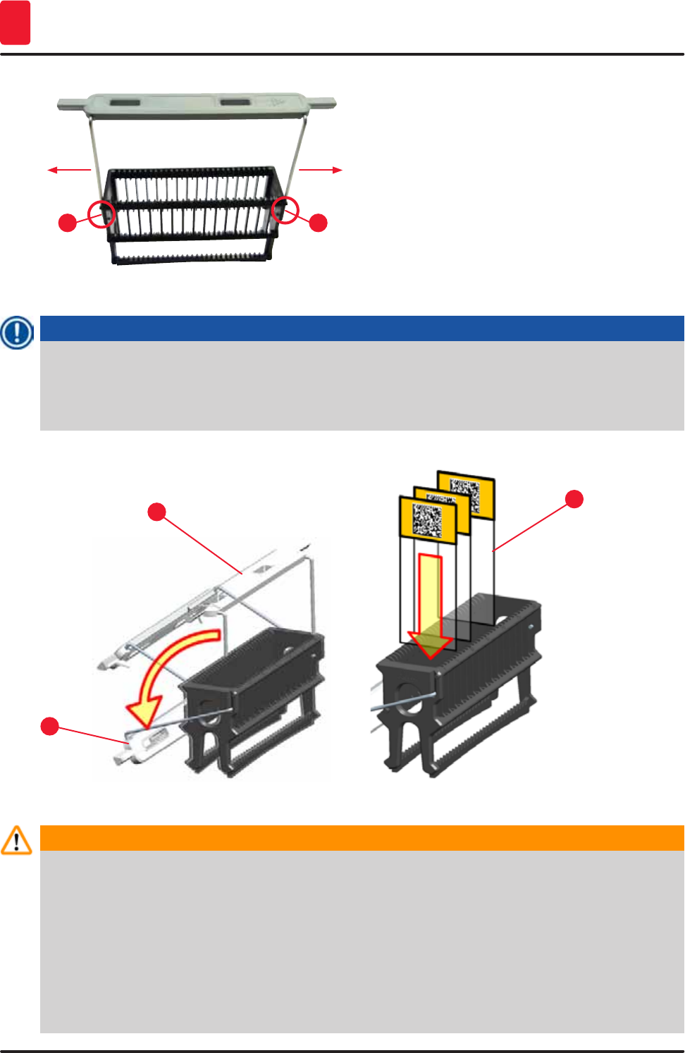
98 Version 1.3, Revision J
Daily instrument setup
6
12
Fig. 81
Note
• Be sure that the handle is correctly positioned in the upper position, centered above the rack
(→ "Fig. 81").
• For stable placement for filling (→ "Fig. 82-3"), fold the handle (→ "Fig. 82-1") to the side as far as
it goes (→ "Fig. 82-2") so it can be used as additional protection to prevent tipping.
Fig. 82
2
13
Warning
• When inserting the specimen slides (→ "Fig. 82-3"), be absolutely certain that the slide label is
facing upwards and toward the user. The side of the slide with the specimen absolutely must be
facing the front side of the rack.
• The front side of the rack is labeled with the Leica logo. With the handle attached, "Front" can be
read when looking at the handle (→ "Fig. 82").
• If the specimen slides are not inserted correctly, the samples can become damaged during the
staining process.
• The stickers and/or labels used on the specimen slides must be resistant to the solvents used in
the instrument.

99
HistoCore SPECTRA ST
Daily instrument setup 6
Note
• Only specimen slides that meet the DIN ISO 8037-1 standard may be used.
• When printable labels or handwritten labels are used on the rack handles and the specimen
slides, they must be checked for solvent resistance prior to use.
• When inserting the specimen slide into the rack, you have to make sure that the slides are
inserted into the respective rack for the desired staining program. The colored rack handles
enable reliable assignment to the respective staining program.
• Make sure that only one specimen slide each is put into the insert space and that the slides are
not jammed in.
6.6 The staining process
The following requirements must be met to carry out the staining process:
• All settings have been optimized (parameters for oven, etc.).
• The programs required for staining have been created (→ p. 69 – 5.9.5 Creating or copying a new
staining program).
• The reagent stations are filled with the correct reagents (→ p. 86 – 6.2.1 Preparation and handling
of reagent vessels).
• A fill level scan has been carried out (→ p. 86 – 6.2 Daily instrument setup).
• The racks intended for staining are filled and the correct handles are attached to them (→ p. 96 –
6.5 Preparing the rack).
Note
Controlled shutdown of the instrument is initiated if the operating switch (→ "Fig. 14") is pressed during
an ongoing staining process (→ p. 106 – 6.6.6 Finishing the daily operation). To do so, the operator
has to confirm shutdown of the instrument by pressing the operating switch twice.
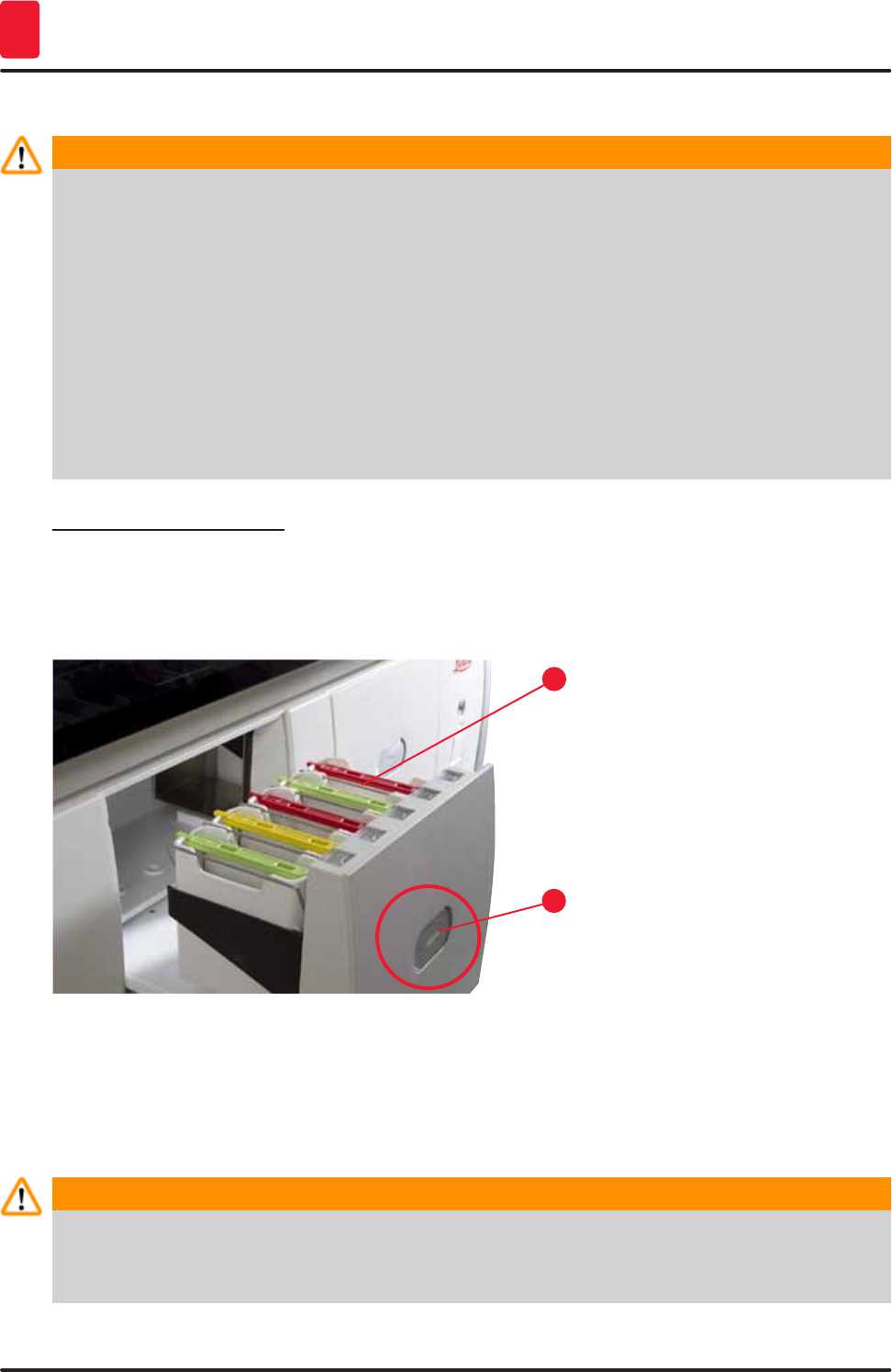
100 Version 1.3, Revision J
Daily instrument setup
6
6.6.1 Starting the staining process
Warning
• To avoid injuries, do not enter the movement area of the input drawer.
• The rack can be inserted only using the input drawer. Directly inserting it into any reagent or
oven station by opening the instrument hood is not permitted. Racks inserted in this way cannot
be recognized by the instrument and may cause collisions!
• Opening the hood when staining programs are active causes delays in the respective processing
steps since no transport movements can take place during this time frame. This can result in
changes to the staining quality.
• Make sure to keep the hood closed if the staining programs are active. Leica assumes no
liability for loss of quality caused by this.
• If racks with white handles have been placed into the input drawer and assigned to a program,
the program will have to be reassigned after the drawer and/or hood is opened again. For this
purpose, observe the messages displayed on the screen.
Starting the staining process
1. Fold the rack handle into the upright position (→ "Fig. 82").
2. If the input drawer is illuminated in green (→ "Fig. 83-1"), press it and open the drawer.
3. As shown in (→ "Fig. 83-2"), insert the rack into an available input drawer position.
1
2
Fig. 83
4. Insert the rack so that both the Leica logo on the front side of the rack and the "Front" label on
the top of the colored handle are pointing toward the user. The arrow on the top of the colored
handle must point into the instrument.
5. Press the input drawer button again to close it again.
6. The user receives a message if the input drawer is open for longer than 60 seconds.
Warning
Exercise caution when opening or closing the drawers! Crushing hazard! The drawers are
motorized and open automatically when the button is pressed. Do not block the extension range of
the drawers.
7. After the input drawer is closed, the instrument detects the RFID chip in the colored handle.
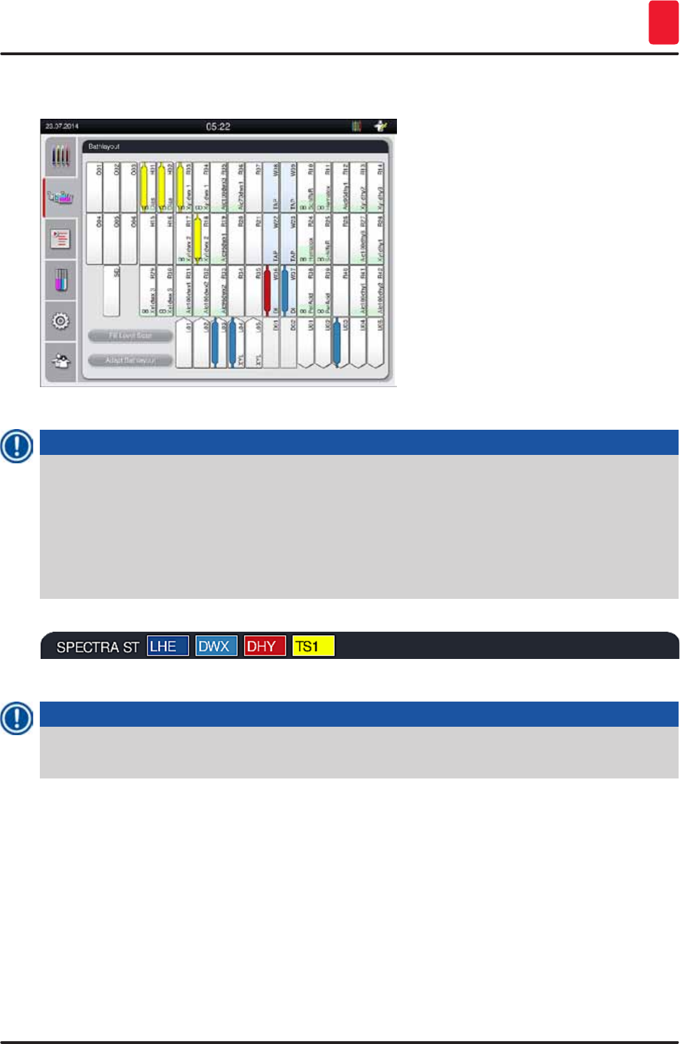
101
HistoCore SPECTRA ST
Daily instrument setup 6
8. The detected handle color and the assigned program abbreviation are displayed in the
bathlayout at the respective station (→ "Fig. 84").
Fig. 84
Note
• The instrument detects and indicates when a rack has been inserted in the wrong orientation
and has to be corrected by the user.
• If a rack has been inserted into the input drawer with a rack handle color for which no program
is specified in the bathlayout (→ "Fig. 85"), the instrument detects this and informs the user by
displaying a message. The rack must be removed from the instrument. Corresponding to the
bootable programs (→ p. 69 – Fig. 45), attach the correct colored handle to the rack and re-
insert it into the input drawer.
Fig. 85
Note
For the inserted racks, the instrument calculates throughput-optimized start times that can deviate
from the order of the inserted racks.
• Before the first program step, the instrument counts the slides that have been inserted into the rack
in the specimen slide reader station (→ "Fig. 4-2").
• The determined number of specimen slides is recorded and processed in the RMS and the
consumption status of the respective reagents is updated.
• Afterwards, the rack is transported into an oven station or reagent station, depending on the defined
first program step.
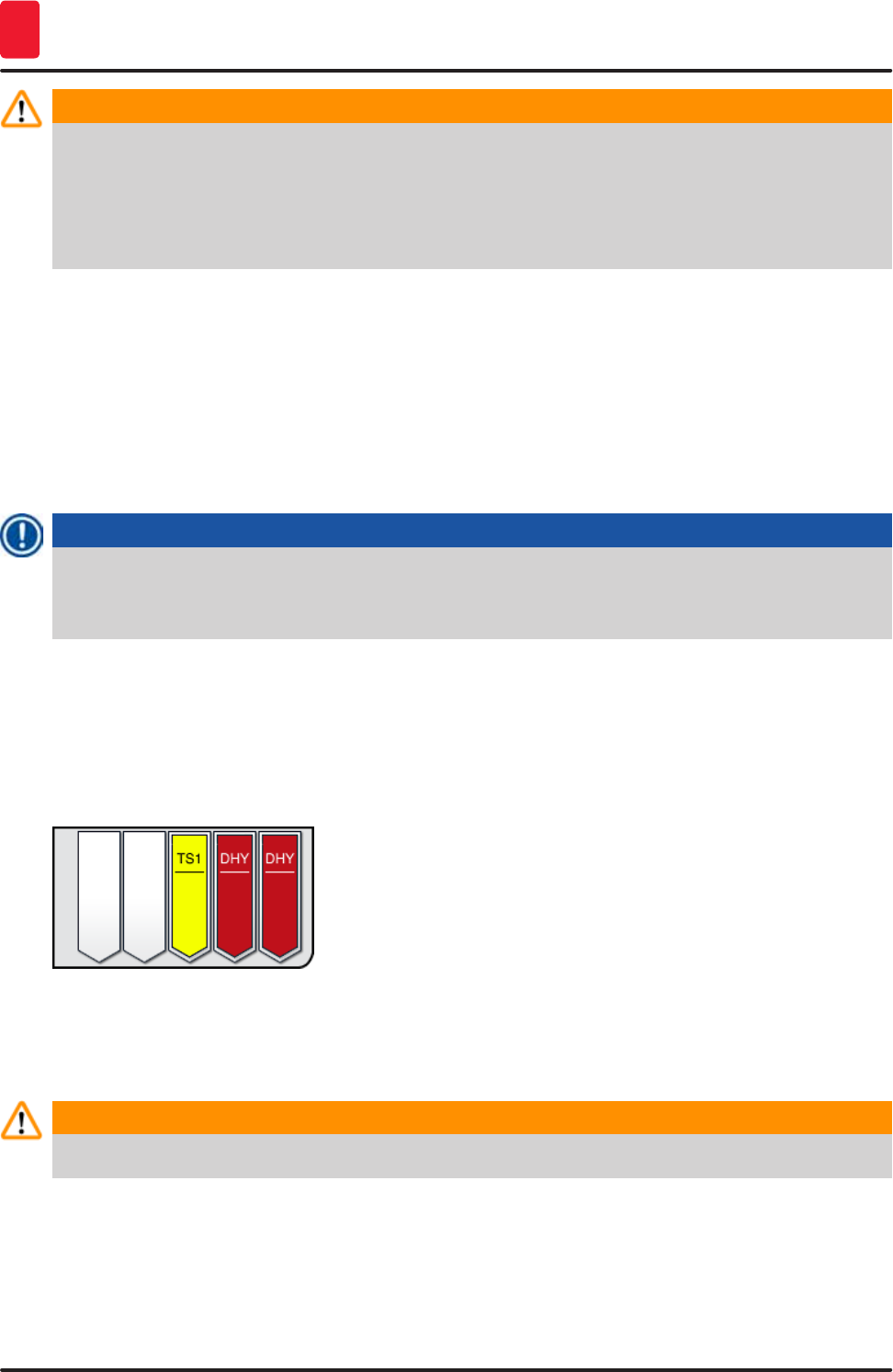
102 Version 1.3, Revision J
Daily instrument setup
6
Warning
If the input drawer and hood of the instrument were inserted simultaneously before starting a
staining process (e.g. for visual inspection of the reagents), the instrument issues a message after
60 seconds that prompts the user to close the input drawer. If the rack is inserted before closing the
input drawer, make sure that the hood is closed and the programs start.
If the program does not start automatically, open the input drawer and close it once more.
6.6.2 Monitoring the staining process
Using the following menu, the user can call up or monitor details for ongoing programs:
• Bathlayout with station details (→ "Fig. 84").
• Process status display with calculated remaining program times and step times (→ p. 35 – 5.3
Process status display).
• The status bar (→ p. 34 – 5.2 Elements of the status display) with date, time and symbols that refer
to messages and warnings that occurred.
Note
The last 20 active messages and warnings can be called up by touching the corresponding symbols
in the status bar (→ "Fig. 17-2") (→ "Fig. 17-3"). This allows the user to learn about up-to-date
situations after being absent from the instrument and to initiate any required actions.
6.6.3 Staining process completed
• After a rack has run through the staining process, it is transported into the output drawer
(→ "Fig. 20-4") and placed in an available position (→ "Fig. 86"). The user is informed of this by a
message and a signal tone.
Fig. 86
• To remove the rack from the unloading station, press the button on the output drawer (→ "Fig. 20-4")
to open it and remove the rack.
• Press the button again after removal to close the output drawer.
Warning
To avoid injuries, do not enter the movement area of the output drawer.
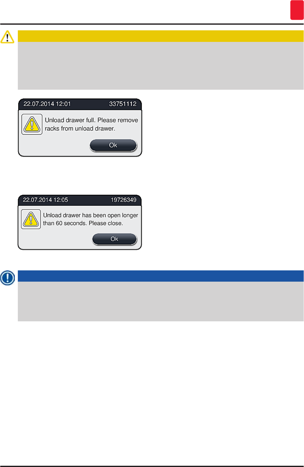
103
HistoCore SPECTRA ST
Daily instrument setup 6
Caution
The output drawer must be opened and the racks must be removed no later than when the warning
message is received indicating that the output station is completely occupied (→ "Fig. 87"). Failure
to comply with the warning message results in not being able to transport further racks into the
output stations. Deviating step times and delays in the staining process may change and ultimately
invalidate the staining results.
Fig. 87
• The user receives a message (→ "Fig. 88") if the output drawer is open for longer than 60 seconds.
Fig. 88
Note
The warning message requests the user to close the output drawer to prevent potential delays.
When the output drawer is open, the instrument cannot place completely processed racks into
the unloading stations. Deviating step times and delays in the staining process may change and
ultimately invalidate the staining results.
• Press the button on the output drawer for closing.
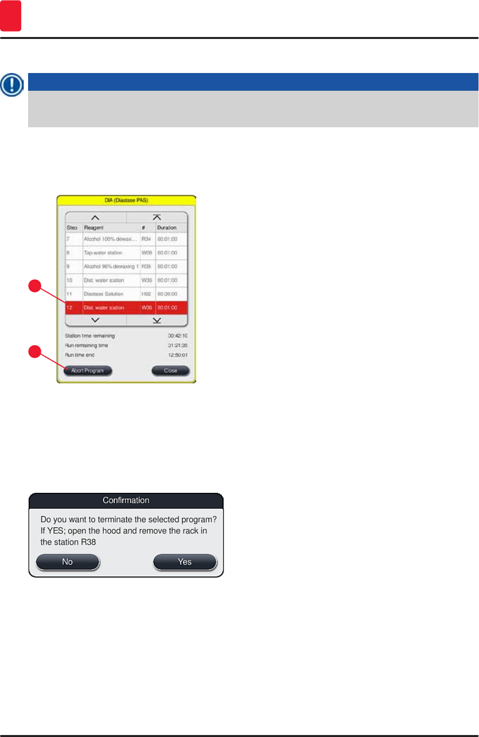
104 Version 1.3, Revision J
Daily instrument setup
6
6.6.4 Canceling the staining program
Note
• Staining programs can only be canceled via the process status display.
• A program that is already in the specimen slide reader station (→ "Fig. 4-2") cannot be canceled.
1. To cancel a staining program, select the corresponding rack in the process status display
(→ "Fig. 18-3") by touching it.
2. A list of program steps (→ "Fig. 89") appears; the current step is marked in red (→ "Fig. 89-1").
1
2
Fig. 89
3. The frame of the window displays the color assigned to the program, the program name and
the stored abbreviation.
4. Press the "Cancel program" (→ "Fig. 89-2") button.
5. In the following message (→ "Fig. 90"), confirm the program termination with the "Yes" button
or return to the process status display with "No".
Fig. 90
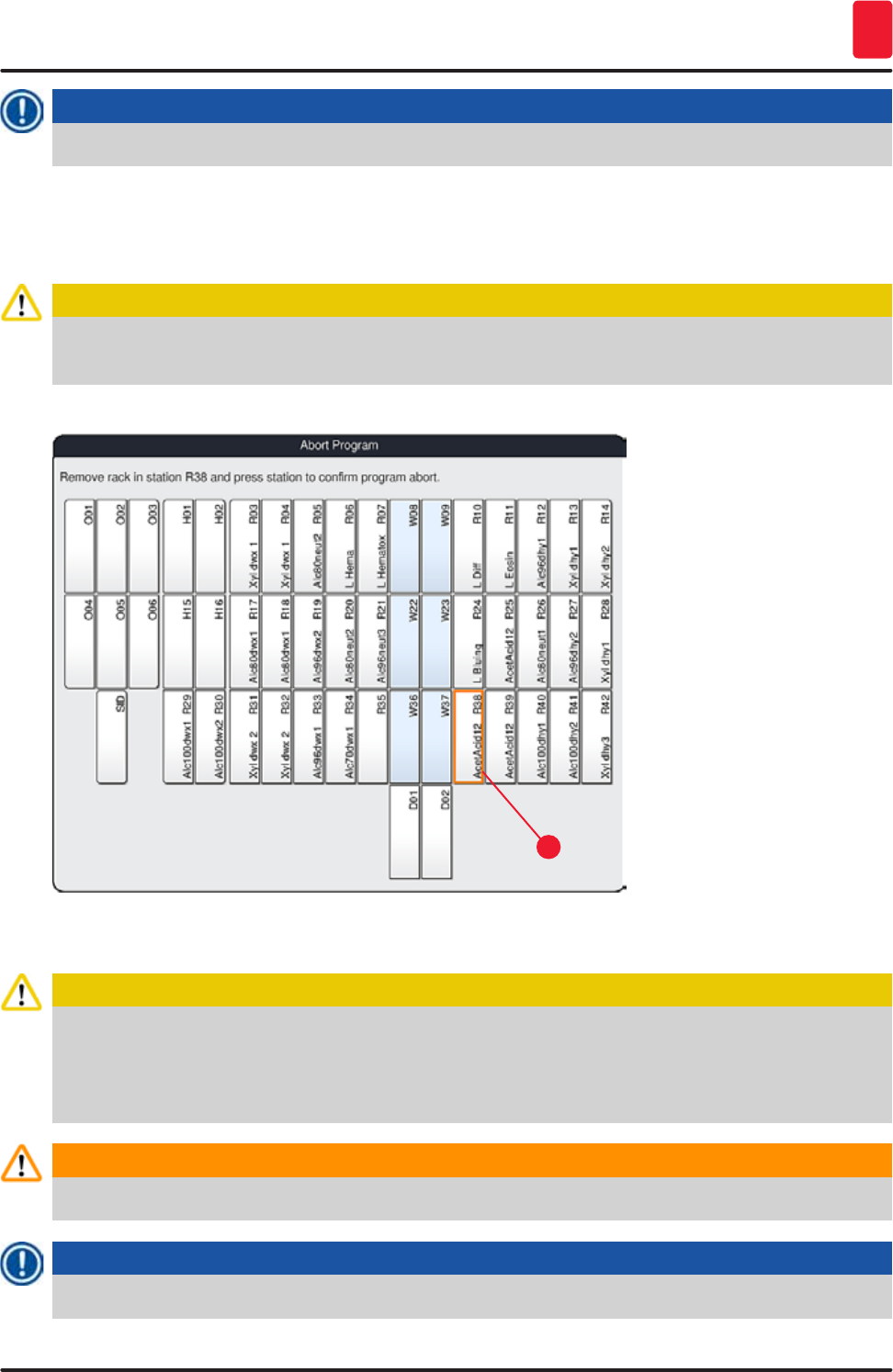
105
HistoCore SPECTRA ST
Daily instrument setup 6
Note
The information in the message (→ "Fig. 90") absolutely must be adhered to.
6. The bathlayout is displayed after pressing the "Yes" button. The position of the rack in the
instrument is marked orange (→ "Fig. 91-1").
7. Open the instrument hood and remove the rack from the highlighted station.
Caution
If the marked station is an oven station, the left transport arm (→ "Fig. 4-1") may have to be shifted to
the center of the instrument. Then, pull the oven cover forward and remove the rack.
• Confirm the removal of the rack by pressing the marked station (→ "Fig. 91-1").
1
Fig. 91
• Then close the hood again.
Caution
When removing the rack, proceed quickly and make sure that the hood remains open only for a
short amount of time. After opening the hood, for safety reasons, all movements are interrupted until
the hood is closed again. Deviating step times, delays and changed staining results can be caused
each time the hood opens in the staining process.
Warning
To avoid injuries, do not enter the movement range of the oven lid (swivel range of the oven).
Note
Remaining staining programs are continued after a program termination.
106 Version 1.3, Revision J
Daily instrument setup
6
6.6.5 Operation as a workstation
The HistoCore SPECTRA ST can be operated as a workstation together with a HistoCore SPECTRA CV
robotic coverslipper. This enables an interruption-free workflow from the staining process up to the
removal of the finished cover slipped slides.
An optional transfer station is available for this purpose (→ p. 135 – 9.1 Optional instrument
components).
Note
The optional transfer station and connection of a HistoCore SPECTRA CV to the
HistoCore SPECTRA ST may be installed subsequently only by a Leica-certified service technician.
Caution
The user must adhere to the following in workstation mode!
• The output stations of the HistoCore SPECTRA ST must be filled with the same reagent (xylene)
as the input station(s) of the HistoCore SPECTRA CV.
• Each reagent added must be compatible with the mountant used.
• Filling the output stations of the HistoCore SPECTRA ST and the input stations of the
HistoCore SPECTRA CV with the same reagent is absolutely necessary, because the racks
are conveyed into the output station during the staining process in the event that the
HistoCore SPECTRA CV is not available. This situation can occur if the reagent vessels of the
input drawer are filled with racks in the HistoCore SPECTRA CV, because the operator did not
refill the consumables in a timely manner or there is an instrument fault.
• A rack for 5 specimen slides cannot be transferred to the HistoCore SPECTRA CV. These racks
are always put into the output drawer at the end of the staining process, regardless of whether
the transfer station was specified in the staining program as the last station.
• The operation as a workstation is described in detail in the Instructions for Use of the
HistoCore SPECTRA CV.
Warning
If the specified stations are not filled as recommended, this can lead to damaged specimens with
lower staining result quality and coverslipping quality. Not filling the specified stations may result
in specimens being ruined from drying out.
6.6.6 Finishing the daily operation
After completing the daily staining operation, the instrument must be set to standby mode:
1. Check the following stations for remaining racks and remove them:
• Input drawer (→ "Fig. 65-9")
• Output drawer (→ "Fig. 65-6")
• Oven (→ "Fig. 65-1")
• Dry transfer station (→ "Fig. 65-7")
• Reagent vessel field (→ "Fig. 65-3"), (→ "Fig. 65-4"), (→ "Fig. 65-5") and (→ "Fig. 65-8")
2. Then cover all reagent vessels with the reagent vessel covers.
3. Push the green operating switch (→ "Fig. 10-2") once.

107
HistoCore SPECTRA ST
Daily instrument setup 6
4. The instrument prompts the user to confirm the shutdown of the device by pressing the
operating switch again.
5. After pushing the operating switch a second time, the instrument shuts down in a controlled
manner.
6. The operating switch is now red and the instrument is in standby mode.
7. Finally, shut off the water supply.
Warning
If cleaning or maintenance work are to be carried out on the instrument, the instrument must also
be switched off at the main switch (→ "Fig. 10-1").

108 Version 1.3, Revision J
Cleaning and Maintenance
7
7. Cleaning and Maintenance
7.1 Important notes about cleaning this instrument
Warning
General instructions:
• Before each cleaning, shut down the instrument using the operating switch (→ "Fig. 10-2") and then
switch it off using the main switch (→ "Fig. 10-1")!
• When cleaning the instrument, wear suitable protective clothing (lab coat and gloves) to protect
from reagents and potentially infectious micro-biological contaminations.
• Liquid must not come into contact with the electrical connections or get inside the instrument or
in the housing below the transport arms.
• When using cleaning agents, observe the manufacturer's safety instructions and the laboratory
regulations valid in the country of use.
• Dispose off spent reagents in accordance with the laboratory guidelines in force in your country!
The following applies to all instrument surfaces:
• Wipe up spilled solvents (reagents) without delay! The hood surface is only conditionally
solvent-resistant at a longer exposure time!
• Do not use any of the following for cleaning the outside surfaces of the instrument: alcohol,
detergents containing alcohol (e.g. window cleaner), abrasive cleaning powders, solvents
containing acetone or xylene.
7.2 Exterior surfaces, varnished surfaces, instrument hood
The surfaces can be cleaned with a mild, pH-neutral, commercially available cleaning agent. After
cleaning the surfaces, wipe them off with a cloth moistened with water.
Caution
Varnished instrument surfaces and plastic surfaces (e.g. the instrument hood) must not be cleaned
with solvents such as acetone, xylene, toluene, xylene substitutes, alcohol, alcohol mixtures and
abrasives! In case of long-term exposure, the surfaces and instrument hood are only conditionally
resistant to solvents.
7.3 TFT touchscreen
Clean the screen using a lint-free cloth. A suitable screen cleaner can be used in compliance with the
manufacturer information.
7.4 Interior and drain pan
• To clean the interior and the drain pan, remove the reagent vessels and rinsing water vessels.
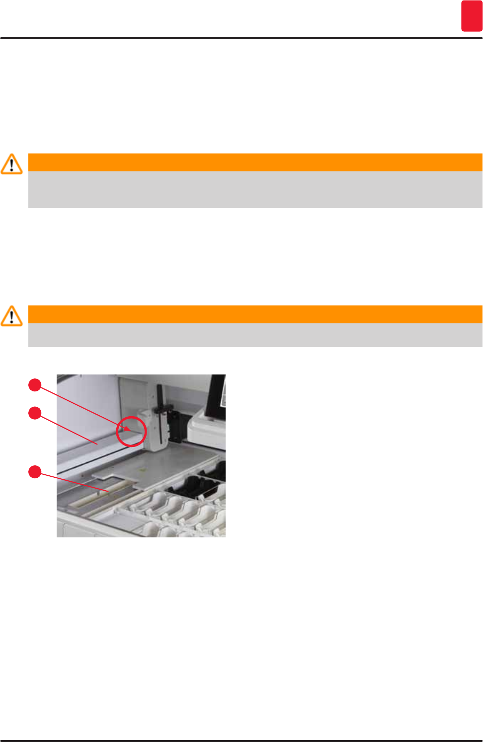
109
HistoCore SPECTRA ST
Cleaning and Maintenance 7
Use a mild, pH-neutral, commercially available cleaning agent to clean these areas.
• After cleaning the drain pan, rinse it thoroughly with water.
7.5 Transport arms
To clean the surfaces of the transport arms (→ "Fig. 92-1"), these are to be wiped off with cloth
moistened with water or with a mild cleaning agent with a neutral pH value.
Warning
Ensure that no liquids spill underneath the housing (→ "Fig. 92-2") of the transport arms because
there are sensitive parts here.
7.6 Specimen slide reader station
Check the recess of the specimen slide reader station for dirt and reagent residue. If specimen slides
that already have damaged edges are used, small glass shards and splinters may have collected there
(→ "Fig. 92-3"). Therefore, all dirt in this area must be carefully removed to prevent injury.
Warning
Wear suitable protective clothing (lab coat and gloves) to protect against cutting injuries.
Fig. 92
2
1
3
7.7 Input and output drawers
• Remove reagent vessels from both drawers and store them outside of the instrument.
• Check the inside of the drawers for reagent residue and remove residue where appropriate.
• Finally, insert the reagent vessels into the correct positions again.
• Observe the existing labeling (→ "Fig. 93-1") for stations in the drawers.
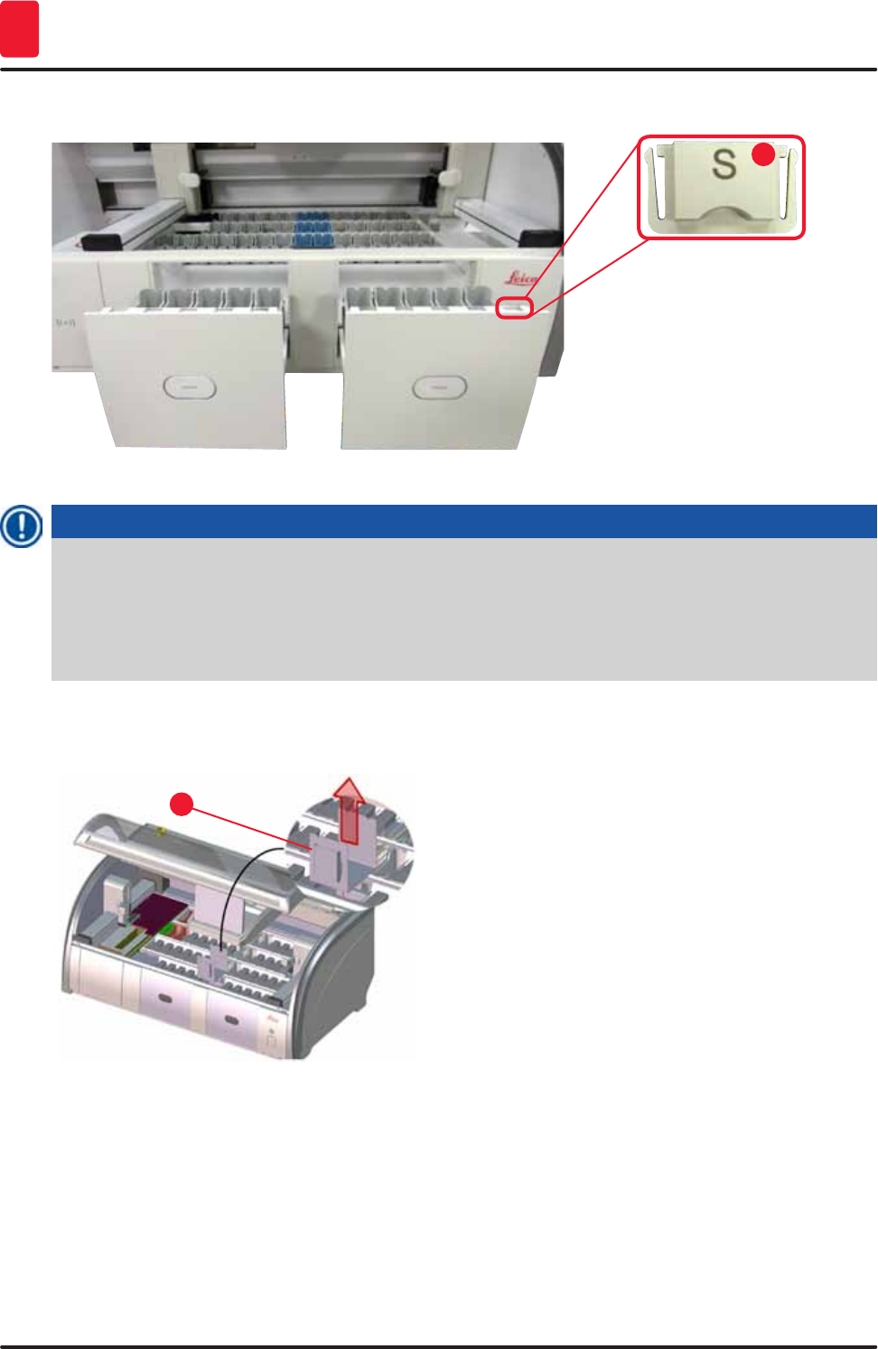
110 Version 1.3, Revision J
Cleaning and Maintenance
7
1
Fig. 93
Note
Use the label covers contained in the (→ p. 19 – 3.1 Standard delivery) to label the reagent vessels
in the input and output drawers. The imprinted letters have the following meanings:
• H2O = water or distilled water
• A= alcohol
• S= solvent, for example, xylene
7.8 Dry transfer station
1
Fig. 94
After inserting the dry transfer station, the
reagents can drip down. This residue must be
removed regularly.
• To do so, remove the insert (→ "Fig. 94-1") of the
dry transfer station by pulling upwards, check
for contamination and clean if necessary.
• Then, re-insert the insert and make sure it
snaps in correctly.
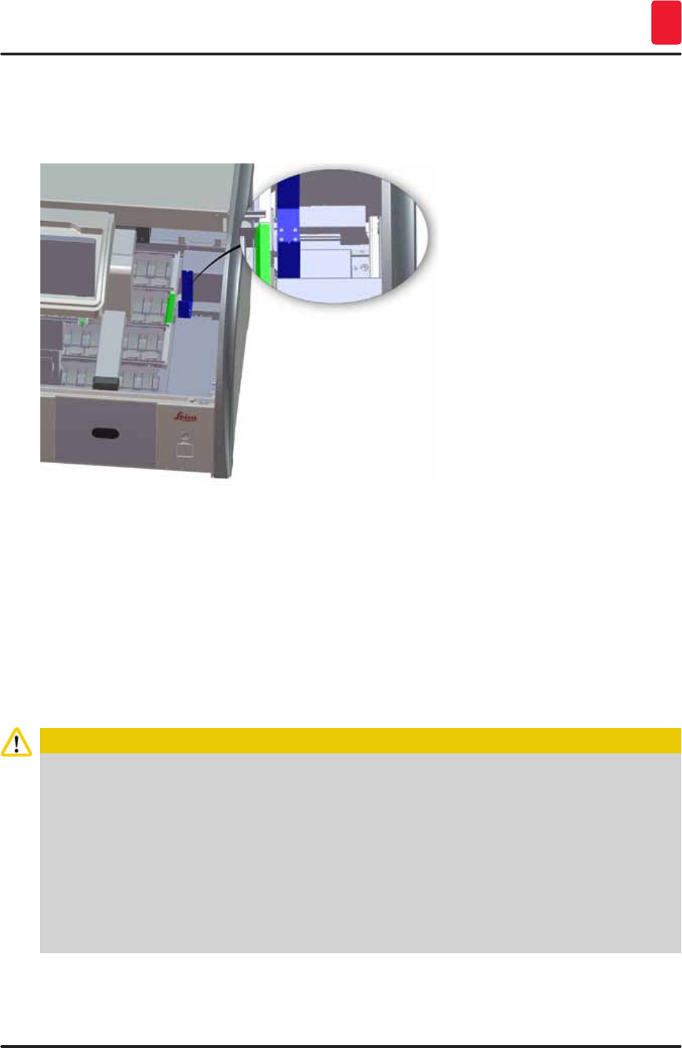
111
HistoCore SPECTRA ST
Cleaning and Maintenance 7
7.9 Transfer station (optional)
• Regularly check the transfer station (→ "Fig. 95") for reagent residue and, if necessary, clean it using
a commercially available, mild cleaning agent with a neutral pH value.
Fig. 95
7.10 Reagent vessels, rinsing water vessels and (optional) heated vessels
• Remove the vessels individually from the handle. Ensure that the handle is in the correct position
(→ p. 86 – 6.2.1 Preparation and handling of reagent vessels) to prevent spilling of the reagent.
• The sealing ring (→ "Fig. 96-1") must remain attached to the rinsing water vessel.
• Dispose of reagents in accordance with the local laboratory specifications.
• Reagent and rinsing water vessels can be cleaned in a dishwasher, at a maximum temperature of
65 °C, using a standard, commercially available detergent for lab dishwashers. The handles can
remain attached to the various vessels during this process.
Caution
• To prevent damage to the coating of coated accessories (inserts for special dyes and specimen
slide handles for 5 specimen slides), these must not be cleaned in a dishwasher. Likewise,
make sure the coating does not get damaged when cleaning manually. If coated accessories
are damaged, they may cause chemical reactions with reagents for special applications
(→ p. 144 – Appendix 1 - Compatible reagents).
• Color reagent vessels have to be pre-cleaned by hand before cleaning in a dishwasher. Remove
as much staining residue as possible to avoid discoloring the remaining reagent vessels in the
dishwasher.
• Never clean plastic reagent vessels at temperatures higher than 65 °C since this can deform
reagent vessels!
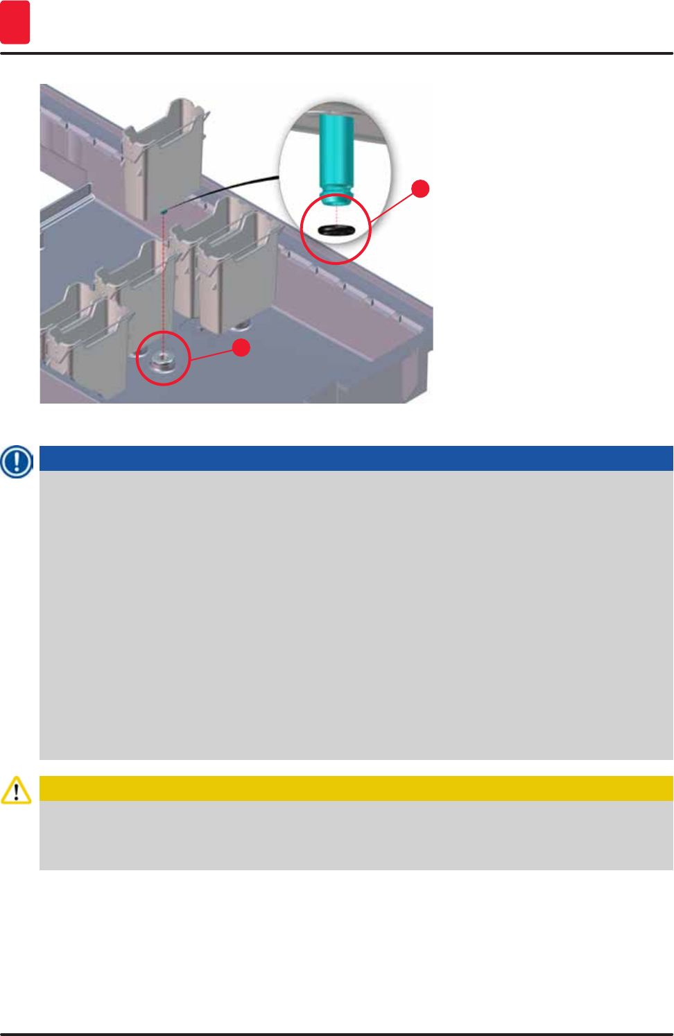
112 Version 1.3, Revision J
Cleaning and Maintenance
7
2
1
Fig. 96
Note
• The rinsing water vessels are to be regularly checked for calcification, visible, microbiological
deposits of bacteria, fungi, algae and permeability. Lime residue can be removed using a mild
vinegar-based cleaning solution. Finally, rinse off the vessels with clear water until the cleaning
agent residue has been removed.
• After cleaning the rinsing water vessels and before inserting them into the instrument again, the
connecting piece to the water inlet system must be checked for correct positioning on the black
O-ring (→ "Fig. 96-1").
• If O-rings are left in the instrument when removing a rinsing water vessel (→ "Fig. 96-2"), remove
them carefully with pincers and stick them back onto the connection port.
• If an O-ring is missing or positioned incorrectly, the rinsing water vessels must not be put back
into position after cleaning, because otherwise there is a danger of the rinsing function being
defective during the staining process.
• After attaching or correcting the position of the O-ring, lubricate it with the Molykote 111 grease
included in the (→ p. 19 – 3.1 Standard delivery).
• Then the rinsing water vessels can be put back into their position.
Caution
If the cleaned and filled reagent vessels are to be put back into the instrument, they need to be put
in the correct position in accordance with the displayed arrangement of the bathlayout (→ p. 75 –
5.9.9 Creating the bathlayout). To do so, switch on and initialize the instrument.
7.11 Rack and handle
• The rack is to be checked regularly for staining residue and other possible contamination.
• The colored handle must be removed from the rack for cleaning.
113
HistoCore SPECTRA ST
Cleaning and Maintenance 7
• To remove staining residue from the racks, immerse it in a bath of lukewarm water and a mild, pH-
neutral lab cleaner and let the cleaner take effect. When doing so, carefully observe the additional
manufacturer information regarding cleaning agents and the recommended application area.
• Then, strong staining contamination can be removed using a brush.
• Now, take your time to thoroughly rinse off the racks with fresh water until no more staining and
cleaning agent residue remains.
• If residue from the coverslip mountant remains on the racks, these can be placed in a bath of solvent.
Caution
The racks and handles must not remain in the solvent for a long time (e.g. several hours or
overnight), because this can lead to deformation!
It is essential to ensure that the solvent being used is compatible with the coverslip mountant.
Xylene or toluene-based mountants can be removed using a xylene bath. Xylene substitute-based
coverslip mountants are removed using a bath containing a corresponding xylene substitute.
Note
The maximum exposure time in a solvent bath is 1-2 hours. The solvent can be washed off with
alcohol. Completely rinse the racks with water, then dry them. If an external drying oven is used for
drying, the temperature must not exceed 70 °C.
7.12 Water drainage
Caution
The draining system within the instrument must be regularly cleaned and checked for correct flow.
If this measure is not completed, the water draining system must become clogged, which could lead
to interruptions or malfunctions in the staining process.
• To clean the water draining system, remove the 4 rear rinsing water vessels (→ "Fig. 65-4") and all
surrounding reagent vessels.
• The remaining reagent vessels have to be covered with lids.
• Remove the drainage sieve and clean it if necessary (→ "Fig. 97-1").
• Place one to two cleaning tablets with active oxygen (e.g. a denture cleanser) into the drain and
dissolve in water to remove various residue (reagents, bacteria, fungi, algae).
• Then, clean the entire curved drainage area inside the instrument with a long, flexible brush
(→ "Fig. 97-2").
• Check the flow by flushing thoroughly with water.
• Insert the drainage sieve again, and put the vessels back in their original, defined positions.
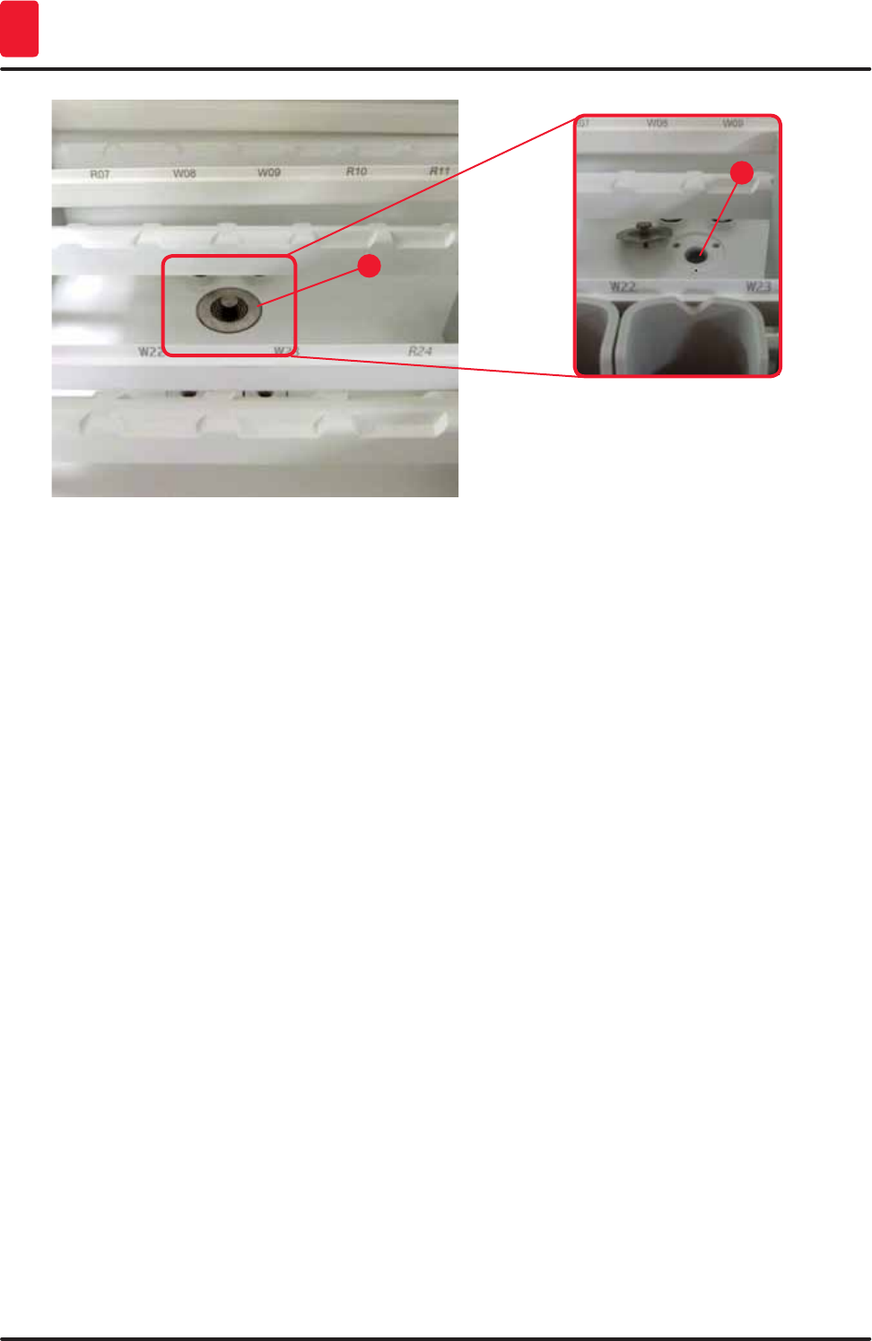
114 Version 1.3, Revision J
Cleaning and Maintenance
7
2
1
Fig. 97
7.13 Water drain hose
The water drain hose must be checked once a year by a service technician authorized by Leica.
7.14 Replacing the filter cartridge of the water intake filter
The water intake filter with filter cartridge should be checked and replaced once a year by a service
technician authorized by Leica.
The integrated water intake filter (→ "Fig. 98") protects instrument's internal water circuit components
from damage due to sediments and mineral deposits.
The water filter storage life depends on the water quality at the installation location. The maximum
lifetime of the water filter is 1 year.
The water intake filter should therefore be checked regularly by looking through the filter housing for
visible dirt.
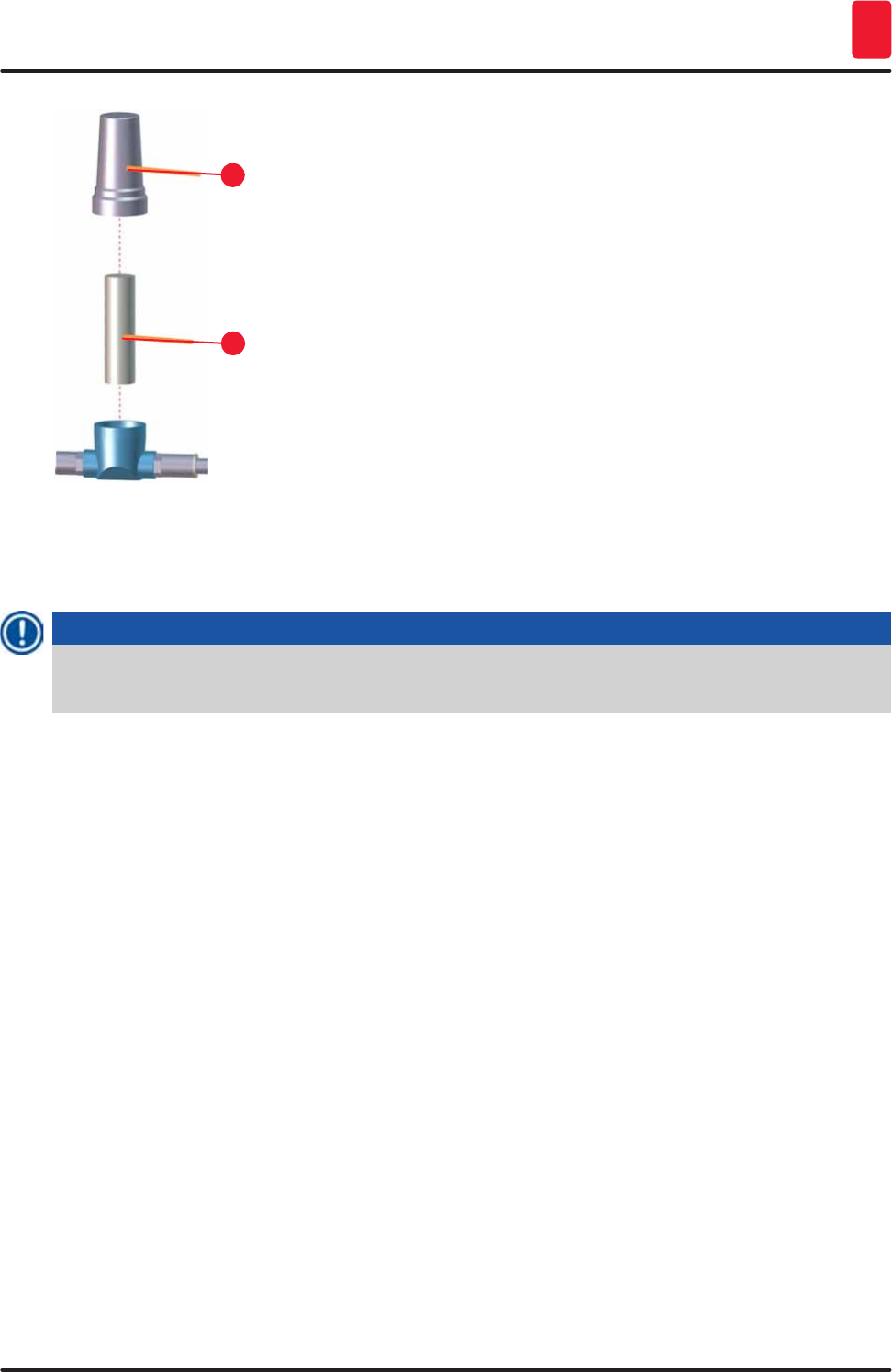
115
HistoCore SPECTRA ST
Cleaning and Maintenance 7
2
1
Fig. 98
1 Filter housing
2 Filter cartridge, Order No. 14 0512 49332
Note
If a significant amount of dirt is visible in the water filter before the maintenance interval (1 year)
expires, it must be replaced by a Leica service technician.
7.15 Changing the active carbon filter
The active carbon filters (→ "Fig. 2-1") installed in the instrument help reduce the amount of reagent
vapors in the exhaust air. The life cycle of the filter can fluctuate strongly depending on intensity of use
and the reagent configuration of the instrument. Therefore, replace the active carbon filter regularly
(every 2-3 months) and dispose of it properly in accordance with the laboratory regulations applicable in
the country of use.
• The filter unit consists of two individual filter elements (→ "Fig. 99-1"), which are accessible to the
user on the front of the instrument.
• They can be accessed without tools and removed by pulling on the pull tabs (→ "Fig. 99-2").
• Insert the new filter elements so that the pull tabs can be reached after they are inserted fully and the
article number (→ "Fig. 99-3") printed on them is legible.
• Note the insertion date for the filter element on the white label and stick the label on the left or right
side of the active carbon filter (→ "Fig. 99-4").
• Both active carbon filters must be pushed in until you feel them make contact with the rear panel of
the instrument.
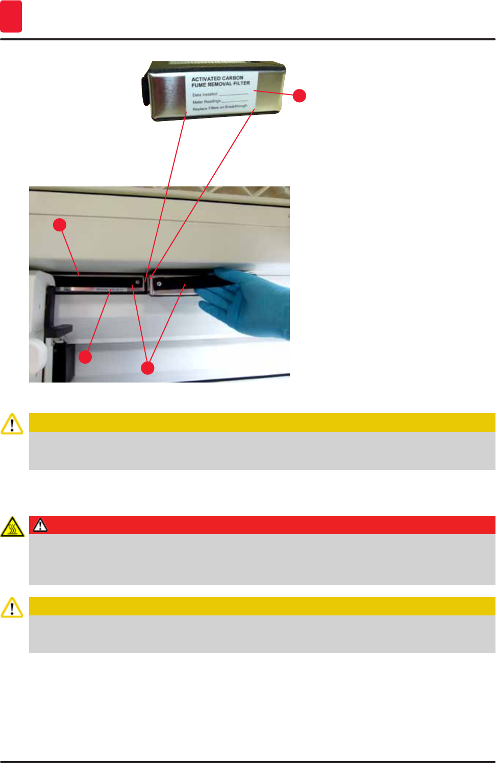
116 Version 1.3, Revision J
Cleaning and Maintenance
7
1
3
2
4
Fig. 99
Caution
If inserted incorrectly, the active carbon filters can protrude into the range of movement of the two
transport arms, thereby impeding or interrupting the staining process.
7.16 Cleaning the ovens
Danger
Beware of hot surfaces: After using the oven in the staining process, first switch the instrument off
before cleaning it and wait at least 10 minutes for it to cool off. Only hold the oven inserts at the
described positions.
Caution
The interior of the oven must not be cleaned using solvents, as there is a risk that solvent residues
will get into the oven and evaporate in the oven when the process begins.
Regularly check for dirt on the sheet metal inserts for catching paraffin residue in the oven.
• Manually pull the movable oven cover (→ "Fig. 100-1") towards the front of the instrument. The oven
cover should not be folded up to the side.
• If necessary, carefully move the left transport arm to the side, so that the oven insert can be easily
accessed.
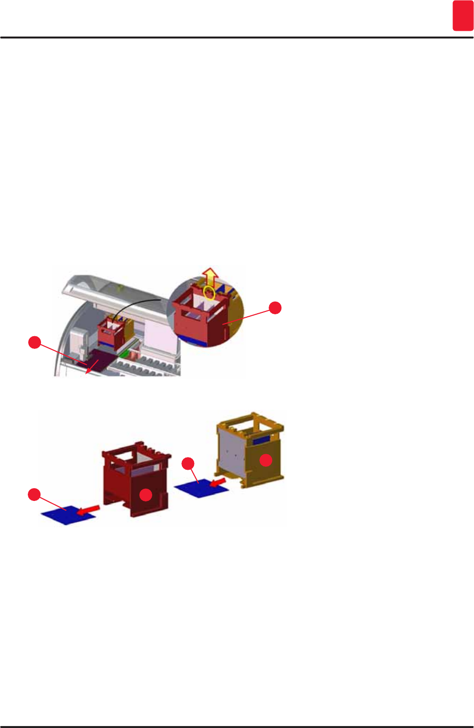
117
HistoCore SPECTRA ST
Cleaning and Maintenance 7
• First grab the front oven insert (→ "Fig. 100-2") by the sides and lift it upwards out of the instrument,
then remove the rear oven insert (→ "Fig. 101-2").
• Disconnect the two oven chambers by pulling them up in opposite directions.
• You can then pull out the insert for catching paraffin residue from the respective oven insert
(→ "Fig. 101-3") and (→ "Fig. 101-4").
• Check the sheet metal inserts for paraffin residue and dirt. To melt the paraffin, the inserts can be
placed in an external laboratory oven.
• After heating, wipe off the paraffin residue with a lint-free cloth.
• Check the ventilation flaps in the oven chambers for proper function. If they are visibly dirty, carefully
clean them with a lint-free cloth.
• Push the sheet metal inserts back into the respective oven insert in the correct orientation
(perforated side facing up).
• After cleaning, first put the rear oven insert (→ "Fig. 101-2") back into the instrument in the correct
position and then put back the front oven insert (→ "Fig. 100-2"). Observe the correct positioning of
the connected oven inserts.
2
1
Fig. 100
1
3
2
4
Fig. 101
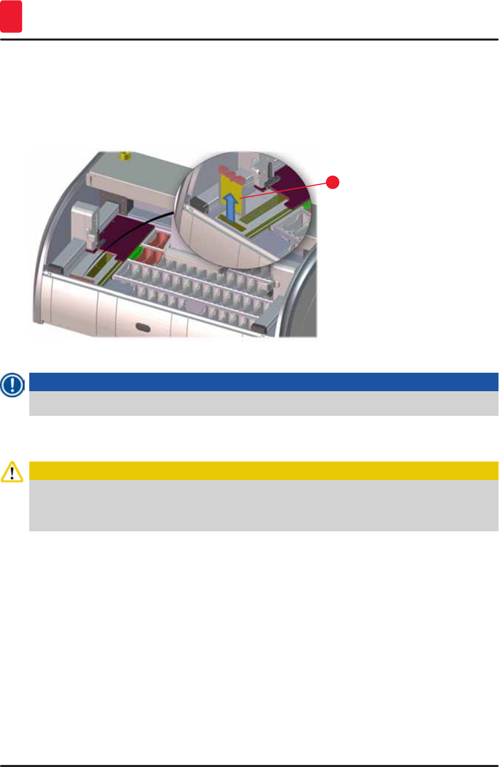
118 Version 1.3, Revision J
Cleaning and Maintenance
7
7.17 Oven air filter
The air filter of the oven should be regularly checked, cleaned or replaced.
• To do so, remove the filter insert (→ "Fig. 102-1") and shake it out or replace it with a new filter insert
(→ p. 135 – 9.2 Optional accessories).
• After checking and cleaning, re-insert into the oven in the same way.
1
Fig. 102
Note
The installation is carried out in reverse order.
7.18 Maintenance and cleaning intervals
Caution
• You must carry out the maintenance and cleaning tasks listed below.
• The instrument must be inspected once per year by a qualified service technician authorized by
Leica in order to ensure the continuous functional capability of the instrument.
To ensure trouble-free operation of the instrument over a long period of time, the following is strongly
recommended:
• At the end of the warranty period, enter into a service contract. For more information, contact the
relevant customer service organization.

119
HistoCore SPECTRA ST
Cleaning and Maintenance 7
7.18.1 Daily cleaning and maintenance
Caution
If sensitive instrument parts and areas get very dirty or if reagents are spilled, they must be cleaned
immediately, as a reliable workflow is not guaranteed otherwise.
1Checking and filling/refilling the reagent vessels. (→ p. 86 – 6.2.1 Preparation and handling of
reagent vessels)
2Covering the reagent vessels and, if necessary,
storing them with covers in a refrigerator.
3Checking the rack and handles for paraffin or
dye residue and broken glass.
(→ p. 112 – 7.11 Rack and handle)
4Check the specimen slide reader station for
reagent residue and clean it if necessary.
(→ p. 109 – 7.6 Specimen slide reader
station)
5Check the surface in the area of the input and
output drawers for solvent residue and clean it if
necessary.
(→ p. 109 – 7.7 Input and output drawers)
6Clean the insert of the dry transfer station and
clean if necessary.
(→ p. 110 – 7.8 Dry transfer station)
8Check the transfer station (optional) for reagent
residue and clean it if necessary.
(→ p. 111 – 7.9 Transfer station (optional))
7.18.2 Cleaning and maintenance as necessary
1Clean the screen using a lint-free cloth. A
screen cleaner can be used according to
manufacturer instructions.
(→ p. 108 – 7.3 TFT touchscreen)
2Clean outer/painted surfaces. (→ p. 108 – 7.2 Exterior surfaces, varnished
surfaces, instrument hood)
3Clean the instrument cover. (→ p. 108 – 7.2 Exterior surfaces, varnished
surfaces, instrument hood)
7.18.3 Weekly cleaning and maintenance
1Check/clean the rinsing water vessels for
bacterial contamination and check the sealing
rings to make sure that they are present.
(→ p. 111 – 7.10 Reagent vessels, rinsing
water vessels and (optional) heated vessels)
2Clean the reagent vessels. (→ p. 111 – 7.10 Reagent vessels, rinsing
water vessels and (optional) heated vessels)

120 Version 1.3, Revision J
Cleaning and Maintenance
7
4Clean the racks and handles. (→ p. 112 – 7.11 Rack and handle)
5Check the water drain and sieve within the
instrument for proper function and clean it if
necessary.
(→ p. 113 – 7.12 Water drainage)
6Checking transport arms for dirt and clean if
necessary.
(→ p. 109 – 7.5 Transport arms)
7.18.4 Monthly maintenance and cleaning
1Check the water intake filter (look through filter
housing).
(→ p. 114 – 7.14 Replacing the filter cartridge
of the water intake filter)
2Check, clean or, if necessary, replace the air
filter of the drying oven with a new one.
(→ p. 135 – 9.2 Optional accessories)
(→ p. 118 – 7.17 Oven air filter)
3Cleaning the drip tray. (→ p. 108 – 7.4 Interior and drain pan)
4Checking the drying oven insert and catch tray
for paraffin residue and cleaning it.
(→ p. 116 – 7.16 Cleaning the ovens)
7.18.5 Cleaning and Maintenance Every Three Months
1Changing the active carbon filter. (→ p. 115 – 7.15 Changing the active carbon
filter)
7.18.6 Annual maintenance and cleaning
1Checking and maintenance of the instrument by
a service technician authorized by Leica.

121
HistoCore SPECTRA ST
Malfunctions and Troubleshooting 8
8. Malfunctions and Troubleshooting
8.1 Fault remedies for instrument malfunctions
Error/problem Cause Troubleshooting
Rising water level in the drain
pan with alarm.
Water drain partially or
completely blocked
Checking and maintaining the
water drain hose (→ "Fig. 8-1").
For this purpose, contact the
responsible Leica service.
Water drainage system inside
the instrument and/or the
drainage sieve partially or
completely blocked.
Checking and maintaining
the water drain system in the
instrument.
Observe the cleaning
instructions in the (→ p. 118 –
7.18 Maintenance and cleaning
intervals).
If the blockage remains, the
water inflow to the rinsing water
vessels is stopped and the
staining process is interrupted.
Therefore, the specimens
have to be removed from the
instrument and put into a safe
position or temporary storage
(→ p. 123 – 8.2 Power failure
scenario and instrument
malfunction).
Decreased flushing during the
staining cycles with possibly
inconsistent staining results.
Water inlet in rinsing water
vessels attenuated/blocked.
Possible causes:
• Rinsing water vessels fit
incorrectly (note O-ring).
• Calcification of the rinsing
water vessel.
Monitoring and maintaining the
rinsing water vessels.
Observe the cleaning
instructions (→ p. 111 – 7.10
Reagent vessels, rinsing water
vessels and (optional) heated
vessels).
Observe regular maintenance
intervals.
Rinsing water vessels do not
drain automatically during
breaks in operation of the
instrument. Standing water can
be a source for microbiological
contamination in the rinsing
water vessel and the samples.
The additional water drain
hole at the base of the rinsing
water vessels is blocked by
calcification/dirt.
Monitoring and maintaining the
rinsing water vessels.
Observe the cleaning
instructions (→ p. 111 – 7.10
Reagent vessels, rinsing water
vessels and (optional) heated
vessels).
Observe regular maintenance
intervals.

122 Version 1.3, Revision J
Malfunctions and Troubleshooting
8
Error/problem Cause Troubleshooting
Insufficient flushing during the
staining processes may yield
inconsistent staining results.
Water pressure too low in the
intake drainage system of the
lab or fluctuations at different
times of the day.
The specified minimum
requirements for water pressure
(→ p. 20 – 3.2 Specifications)
must be fulfilled (even in the
event of possible deviations
during the daytime).
Reagent vessels are deformed. Use of reagents that are not
permitted (ex. phenol in Ziehl-
Neelson dye or Gram dye, etc.).
Incorrectly applied cleaning
procedure.
Monitoring the used reagents
using the list of permitted
reagents (→ p. 144 – Appendix
1 - Compatible reagents).
Observe the cleaning
instructions (→ p. 111 – 7.10
Reagent vessels, rinsing water
vessels and (optional) heated
vessels).
Inconsistent staining results The tolerance of the program
step for staining reagents is not
correctly defined.
Inspecting the staining
programs and reagents.
Most short program steps
demand exact compliance with
the staining step. The tolerance
of the reagent must be set to 0 %.
Varying staining results The process classes (paraffin
removal, staining, etc.) for
reagents were not correctly
assigned. This means that the
bathlayout might not have been
optimally created.
Inspection and correction of
the assigned reagent classes
(→ p. 60 – Creating a new
reagent or copying a reagent).
Reagents that are only to be
used by one program are used
by other programs. The reagent
was dirty because it was not
programmed as "Exclusive".
Inspecting and correcting the
programming of respective
reagents.
Insufficient staining quality Water quality does not satisfy
Type 1, ISO 3696
Test the water quality in
accordance with ISO 3696
and adjust the water quality if
necessary.
After drying, tissue does not
adhere well enough to the
specimen slide, and floats away
during the staining process.
For customer-defined programs,
the selected firing time and oven
temperature (or both) are too
low.
Inspecting and correcting
information about firing time and
oven temperature for customer-
defined programs.
The staining processes are
complete, but repeated or
additional programming
(supervisor mode) cannot be
completed.
Programming can only be
completed when the instrument
is in sleep mode; in other words,
no racks may be in progress;
this also includes the output
drawer positions.
Remove racks from the
output drawer, then carry out
programming.
123
HistoCore SPECTRA ST
Malfunctions and Troubleshooting 8
Error/problem Cause Troubleshooting
Initialization of the instrument
cannot be completed.
Arms are blocked. Check that the active carbon
filter is in the correct position.
The automatic fill level scan
shows incorrect results.
Inserted reagent vessel clips
protrude over the reagent vessel
and are incorrectly interpreted
in the fill level scan.
Check the proper placement of
the reagent vessel clip and, if
necessary, correct it.
The automatic fill level scan
shows incorrect results for
the input drawer stations and/
or the dry transfer station.
Individual stations are reported
as "Missing".
Deposits on the bottom of the
empty reagent vessel and/or
dry transfer station influence
the measuring methods of the
automatic fill level scan.
Clean the reagent vessels
and/or the dry transfer station
and remove any clinging lime
residue. Then, repeat the fill
level scan (→ p. 88 – 6.2.2
Automatic fill level scan)
8.2 Power failure scenario and instrument malfunction
Note
For the event of a short-term power failure (in the range of a few seconds), the
HistoCore SPECTRA ST has an internal UPS (uninterruptible power supply). The user is notified in
the event of a short-term power failure via a message on the screen. The message goes away as
soon as the power supply is restored. The event is entered into the event log.
Circumventing longer-term power failure is possible only by using a external UPS (→ p. 30 – 4.3.1
Using an external uninterruptible power supply (UPS)).
In the event of a longer-term power failure (lasting > 3 seconds), the instrument shuts down. The event
is entered into the event log.
The internal UPS ensures that transferable racks are placed in a secure position above two reagent
stations (→ "Fig. 103") to prevent unintentional lowering into an incompatible reagent.
Caution
Reagent displacement can occur as a result of clinging reagents when setting aside a rack. The
affected reagent vessels are to be checked for contamination before starting a staining process and
replaced if necessary (→ p. 95 – Reagent replacement).
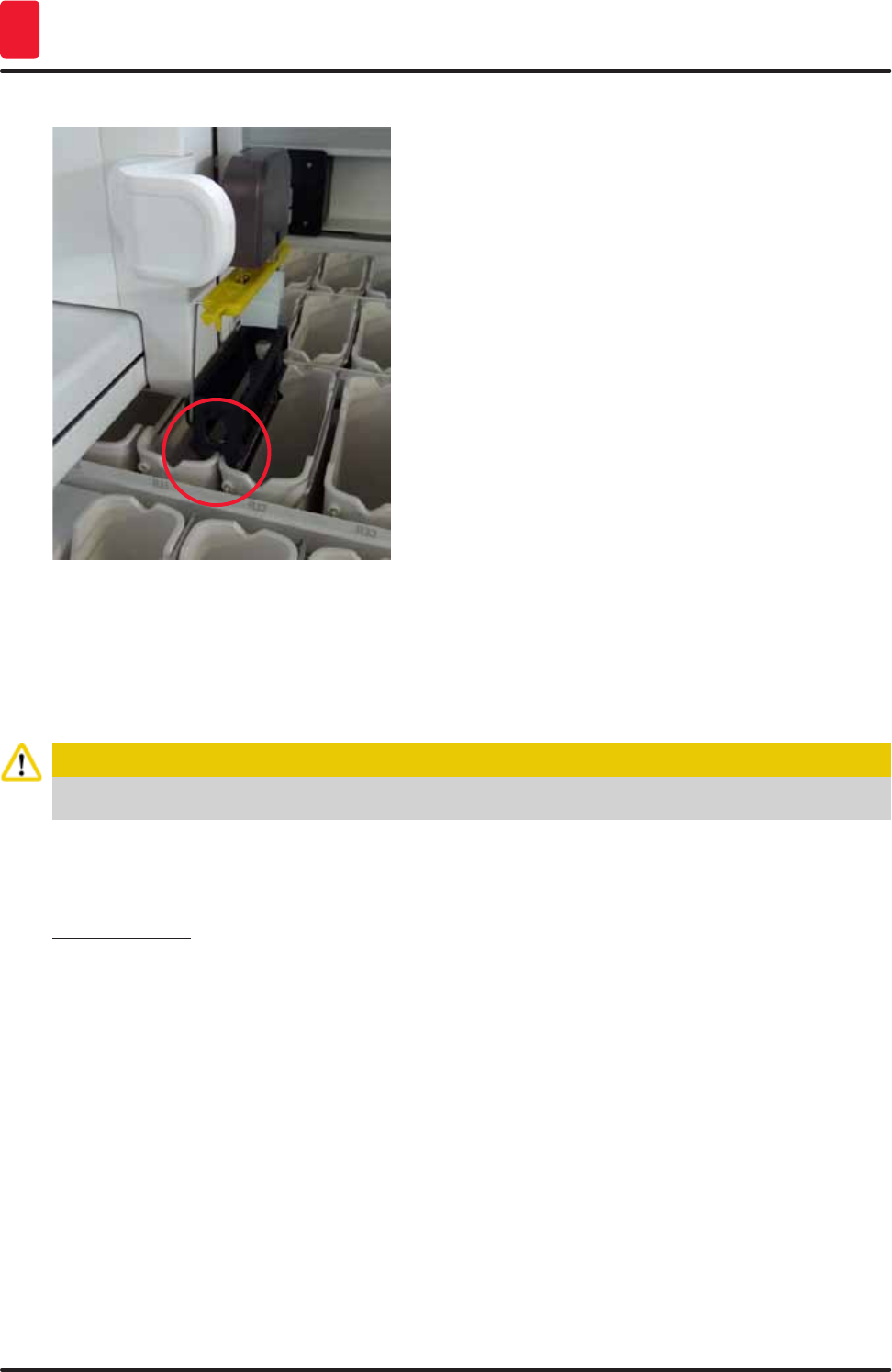
124 Version 1.3, Revision J
Malfunctions and Troubleshooting
8
Fig. 103
The instrument restarts as soon as the power supply is restored.
The instrument software issues a series of messages and instructions to the operator, which provide
him/her with information about the power failure and instruct him/her regarding how to proceed.
The user can cancel or resume the staining process software using the displayed assistance.
Caution
Racks in critical positions must immediately be removed from the instrument by the user.
The reagent stations defined as "critical" positions are those at which excessively long dwell times may
lead to the deterioration of the staining quality or to sample destruction.
Critical positions:
» Rinsing water (→ "Fig. 104-1") and DI water stations (→ "Fig. 104-2")
LVessels can be drained and the specimens can be dried through continuous, automatic water
draining on the floor of the vessel. The specimens are to be removed from the instrument and
stored securely outside of the instrument, i.e. the staining process is to be completed manually.
» Dry transfer station (→ "Fig. 104-3")
LThe specimen are not located in a reagent and could dry out. The specimens are to be removed
from the instrument and stored securely outside of the instrument, i.e. the staining process is to
be completed manually.
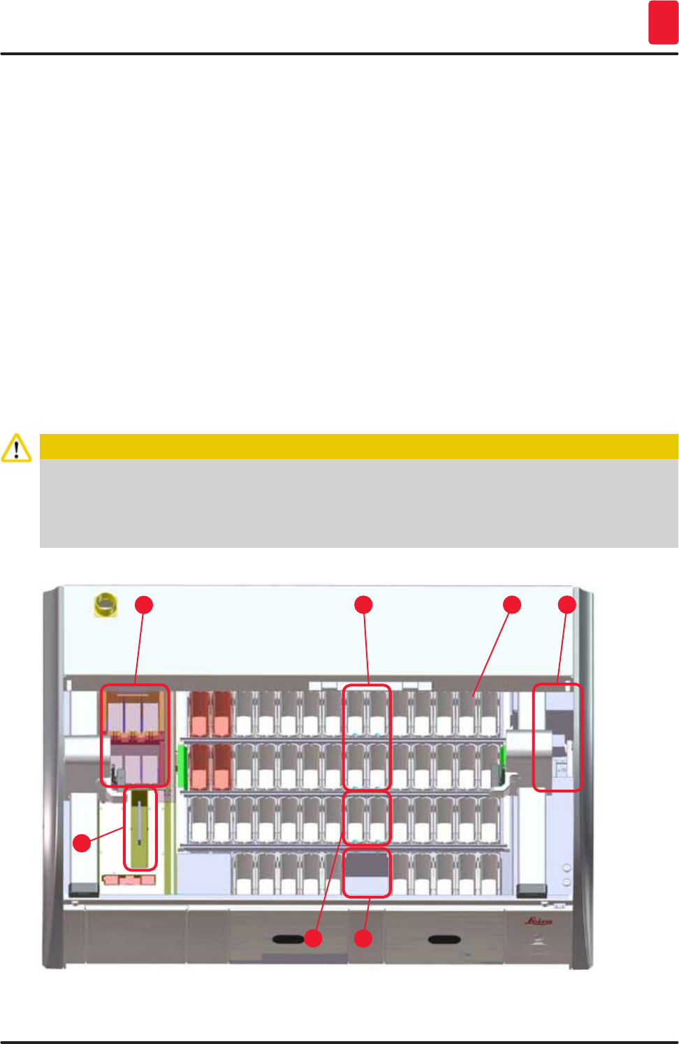
125
HistoCore SPECTRA ST
Malfunctions and Troubleshooting 8
» Specimen slide reader station (SID):(→ "Fig. 104-4")
LIn the event of power failure, a rack inserted into the specimen slide reader station is placed in
a secure location between two reagent stations (→ "Fig. 103"). Remove the rack as described
(→ p. 130 – 8.2.4 Detaching a rack from the gripper mechanism) and re-insert it into the input
drawer.
» Oven stations (→ "Fig. 104-5")
LA drop in temperature in the oven station can occur during longer-term power failure. This could
result in specimens that have not dried properly. The affected racks are to be removed from the
oven and reinserted into the input drawer.
» Transfer station (→ "Fig. 104-8")
LThe specimen are not located in a reagent and could dry out. The specimens are to be removed
from the instrument and stored securely outside of the instrument or manually inserted and
coverslipped in the HistoCore SPECTRA CV input drawer.
Caution
The user is to check whether additional racks are present in the remaining reagent stations
(→ "Fig. 104-6") where excessively long dwell times may lead to a loss in staining quality due to the
reagent used at those specific stations. The specimens are to be removed from the instrument and
stored securely outside of the instrument, i.e. the staining process is to be completed manually.
Fig. 104
1
5
3
2
6
4
8
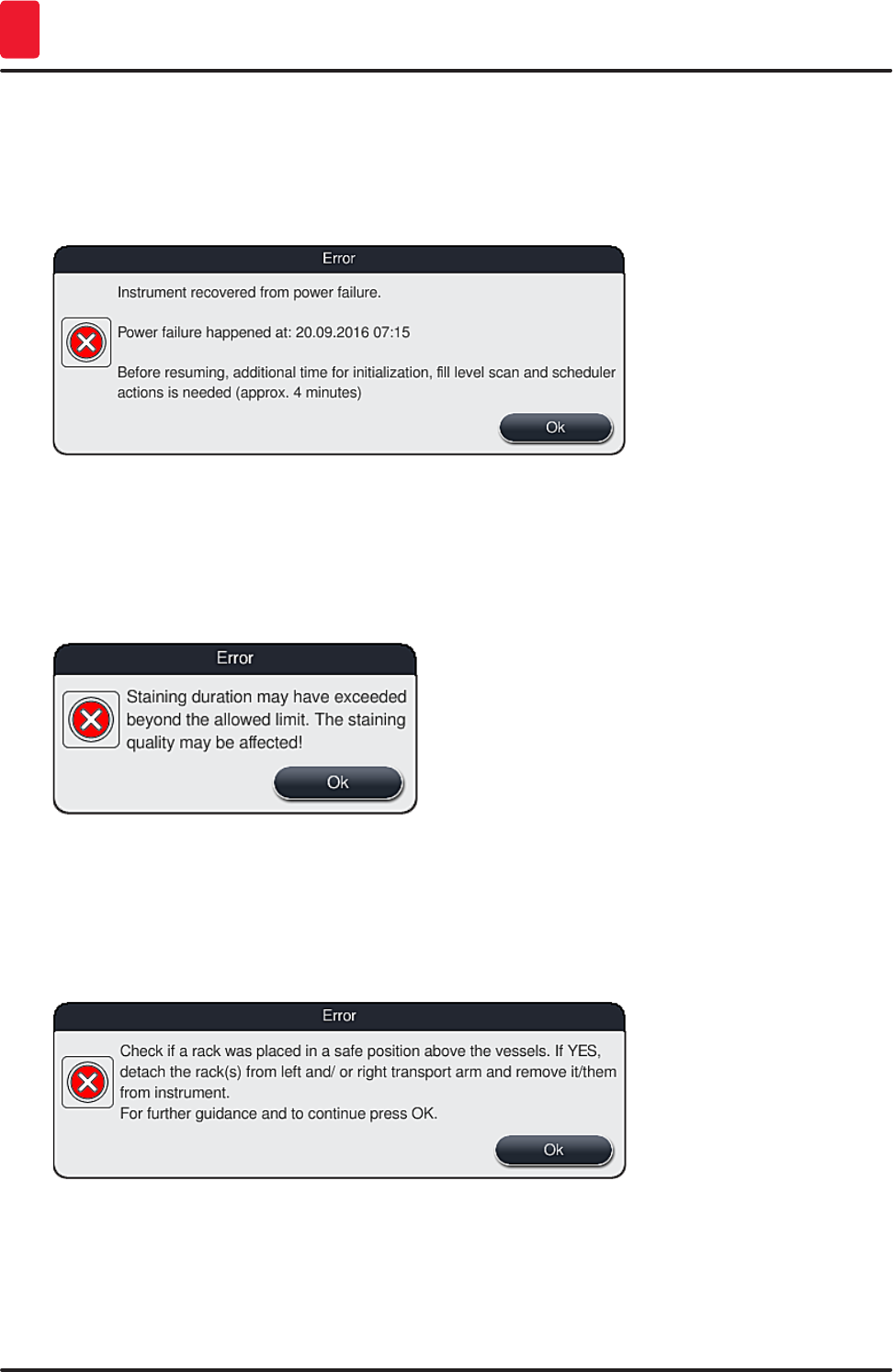
126 Version 1.3, Revision J
Malfunctions and Troubleshooting
8
8.2.1 Procedure after a power failure
LThe first message after the device restarts automatically notifies the operator of the power
failure time (→ "Fig. 105"). Confirm this message by pressing the "OK" button to start the
additional instructions for continuing the staining process.
Fig. 105
1. After confirming this message, the user is informed that the staining periods may have been
exceeded, i.e. individual racks have already spent too much time in a reagent under certain
circumstances or in a critical station, which can impede the staining quality. Confirm this
message (→ "Fig. 106") by pressing the "OK" button to resume.
Fig. 106
2. Subsequently, this messages prompts the user to check (→ "Fig. 107") whether or not the
instrument has placed one or two racks in a secure position between two reagent vessels
(→ "Fig. 103").
Fig. 107
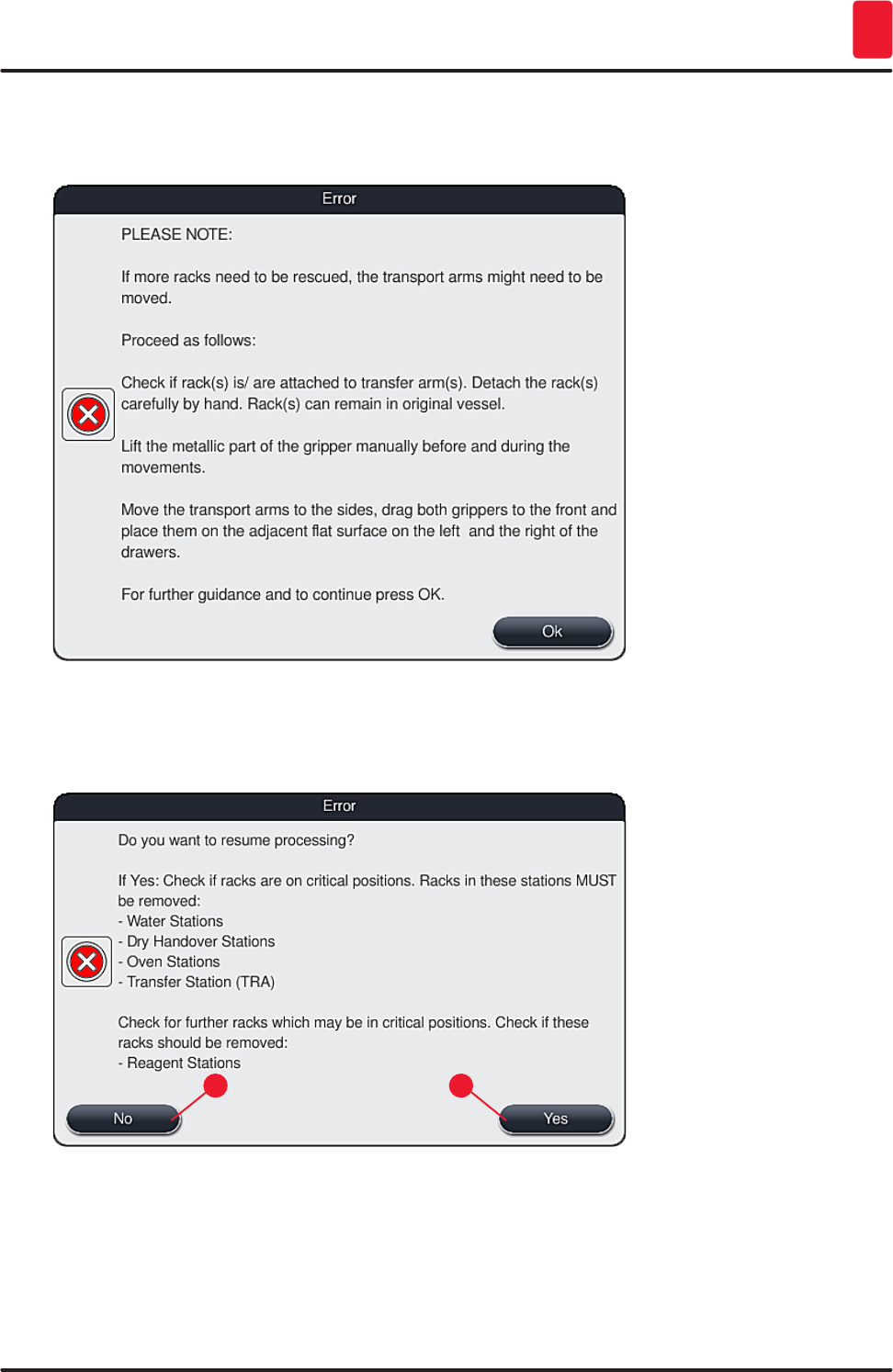
127
HistoCore SPECTRA ST
Malfunctions and Troubleshooting 8
3. After pressing the "OK" button (→ "Fig. 107"), another messages appears (→ "Fig. 108")
that provides the user with instructions regarding the correct procedure for removing the
respective racks.
Fig. 108
4. Subsequently, the user has the option of selecting whether or not the staining process is to be
resumed (→ p. 127 – 8.2.2 Resuming the staining process after a power failure) or canceled
(→ p. 129 – 8.2.3 Canceling all staining processes after a power failure) (→ "Fig. 109").
1
2
Fig. 109
8.2.2 Resuming the staining process after a power failure
1. To resume the staining process, press the "Yes" button (→ "Fig. 109-1").
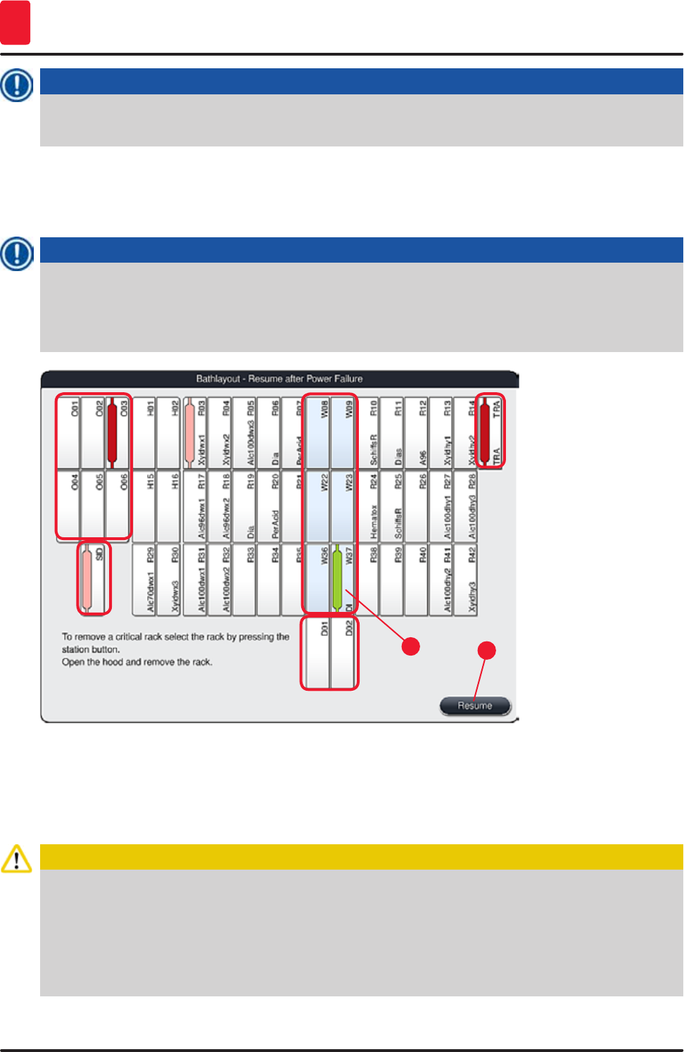
128 Version 1.3, Revision J
Malfunctions and Troubleshooting
8
Note
In the following menu, the racks in progress are displayed in the overview of the bathlayout
(→ "Fig. 110").
2. (→ "Fig. 109") Remove the critical racks from the instrument in accordance with the previous
message and confirm the removal by pressing the corresponding station (→ "Fig. 110-1") on the
screen.
Note
• It is only possible to remove the racks in progress at the time of the power failure using the
method described here.
• The specimen of the removed racks are to be stored secured outside of the instrument, i.e. the
staining process is to be completed manually.
Fig. 110
12
3. If all critical racks have been removed, press the "Resume" button, observe the following
message and confirm by pressing the "OK" button.
4. Finally, the instrument carries out an automatic level check and resumes the staining process
for the racks remaining in the instrument.
Caution
• The remaining racks in the input drawer are not detected under certain circumstances. In this
case, open the input drawer and close it again.
• A program must be assigned to white racks again.
• For white racks, the input drawer must also be opened and the specimen slide marking must
be inspected for the identification of the correct program to determine which program is to be
reassigned.
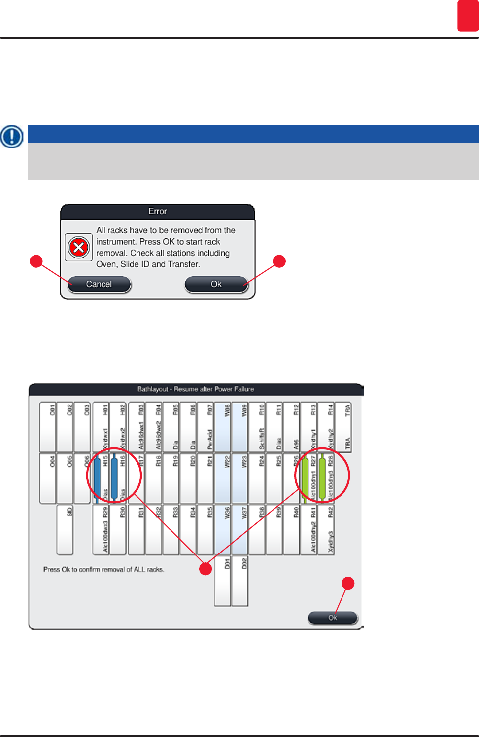
129
HistoCore SPECTRA ST
Malfunctions and Troubleshooting 8
8.2.3 Canceling all staining processes after a power failure
1. If the staining process for all racks is to be canceled, press the "No" (→ "Fig. 109-2") button and
confirm the following warning message by pressing "OK" (→ "Fig. 111-1") to begin the removal
of the racks.
Note
The cancellation of the staining process and the return to the previous selection menu (→ "Fig. 109")
can be undone by pressing the "Cancel" button (→ "Fig. 111-2").
Fig. 111
1
2
2. Open the instrument cover and remove all racks.
3. Confirm the removal of the rack by touching the corresponding station (→ "Fig. 112-1") on the
screen .
Fig. 112
1
2
4. After removing all of the racks successfully, press the "OK" button (→ "Fig. 112-2") to leave the
menu and to resume the initialization of the instrument.
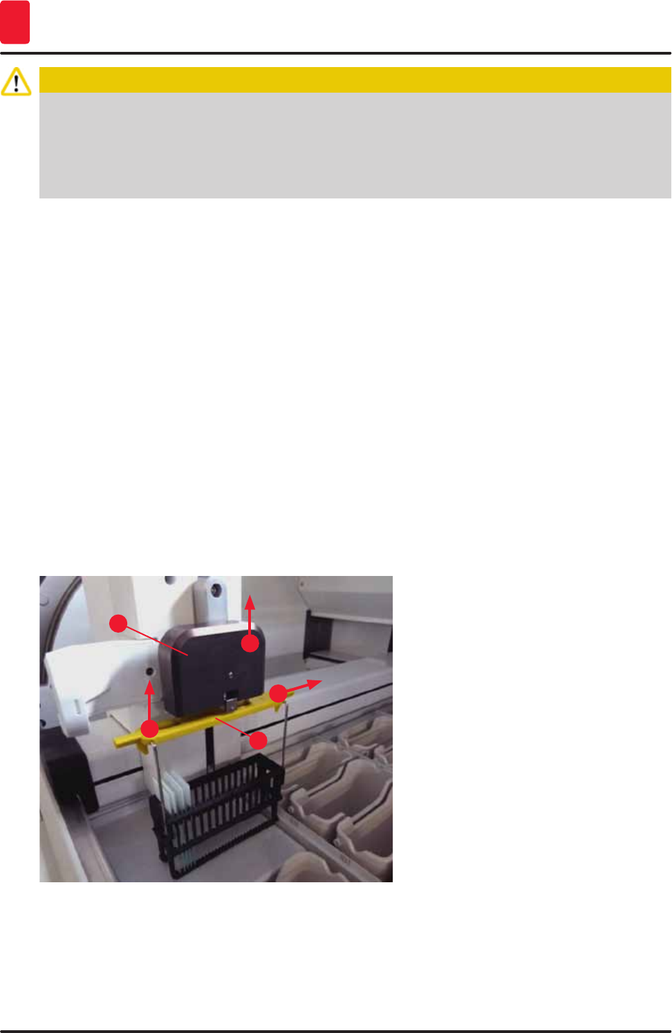
130 Version 1.3, Revision J
Malfunctions and Troubleshooting
8
Caution
• The remaining racks in the input drawer are not detected under certain circumstances. In this
case, open the input drawer and close it again.
• A program must be assigned to white racks again.
• For white racks, the input drawer must also be opened and the specimen slide marking must be
checked to identify the correct program.
After removing the critical racks from the instrument, the remaining racks are further processed
and new racks can be inserted into the input drawer.
8.2.4 Detaching a rack from the gripper mechanism
LThe racks are secured on the bottom of the gripper mechanism by the gripper mechanism
using two hooks. In the event of a power failure, the rack must be released from the gripper
mechanism for the removal from the instrument.
1. Grasp with one hand under the colored rack handle (→ "Fig. 114-2") and push it upwards
slightly (→ "Fig. 114-3").
2. Slide the rack approx. 1 cm toward the inside of the specimen (→ "Fig. 114-4").
3. Grasp the gripper mechanism (→ "Fig. 114-1") with your free hand, slide it upwards
(→ "Fig. 114-5") and firmly hold.
4. The rack can now be removed from the instrument and set aside.
5. Finally, pull the gripper mechanism forwards and carefully place it on the free surface next to
the left input drawer (→ "Fig. 115-3") or next to the right output drawer (→ "Fig. 115-6").
1
32
4
5
Fig. 114
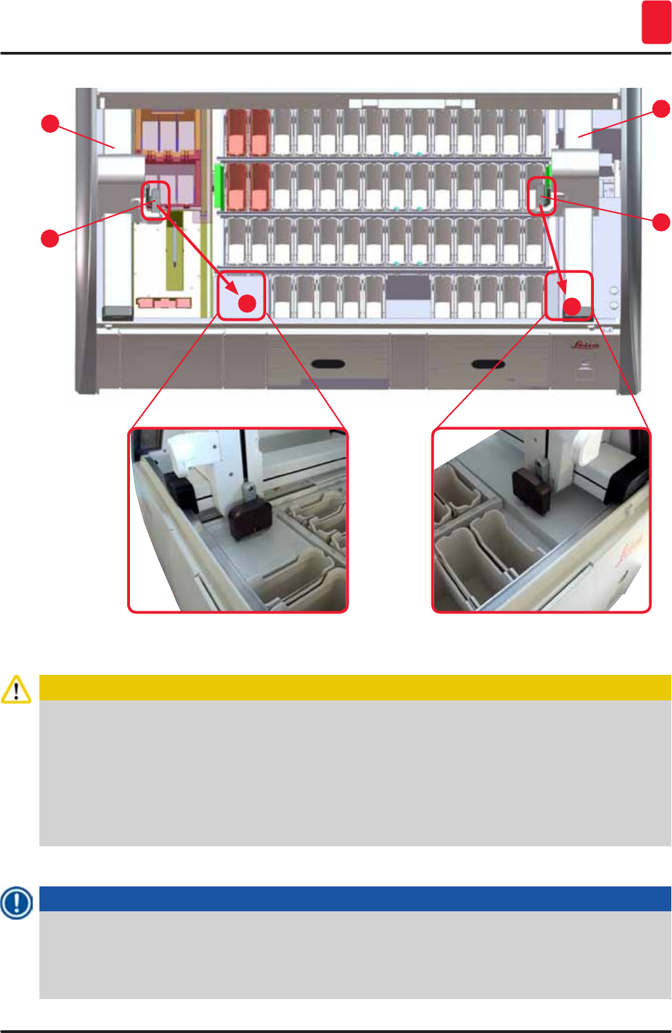
131
HistoCore SPECTRA ST
Malfunctions and Troubleshooting 8
5
36
4
2
1
Fig. 115
Caution
After restarting the instrument, an error message appears which can be used to call up the
bathlayout (→ "Fig. 40") for assistance in removing the specific rack. All racks in progress must be
removed from the instrument by the user manually. Also check the specimen slide reader station
(→ "Fig. 4-2") and the oven (→ "Fig. 4-10") on the rack and replace these if necessary:
The specimens must be stored outside of the instrument in a suitable reagent and the steps of the
already started staining programs must be continued manually until the end of the program. The
user shall be responsible for further processing of the samples.
• After the power supply is restored, the instrument can be restarted and loaded with new specimens.
Note
In the event of severe instrument malfunctions requiring removal of specimens from the instrument
due to a disruption in the staining process, the procedure in the outlined power failure scenario
must be followed. Severe instrument malfunctions are indicated by a defined alarm sound
(→ p. 45 – 5.7.4 Alarm and signal tones).
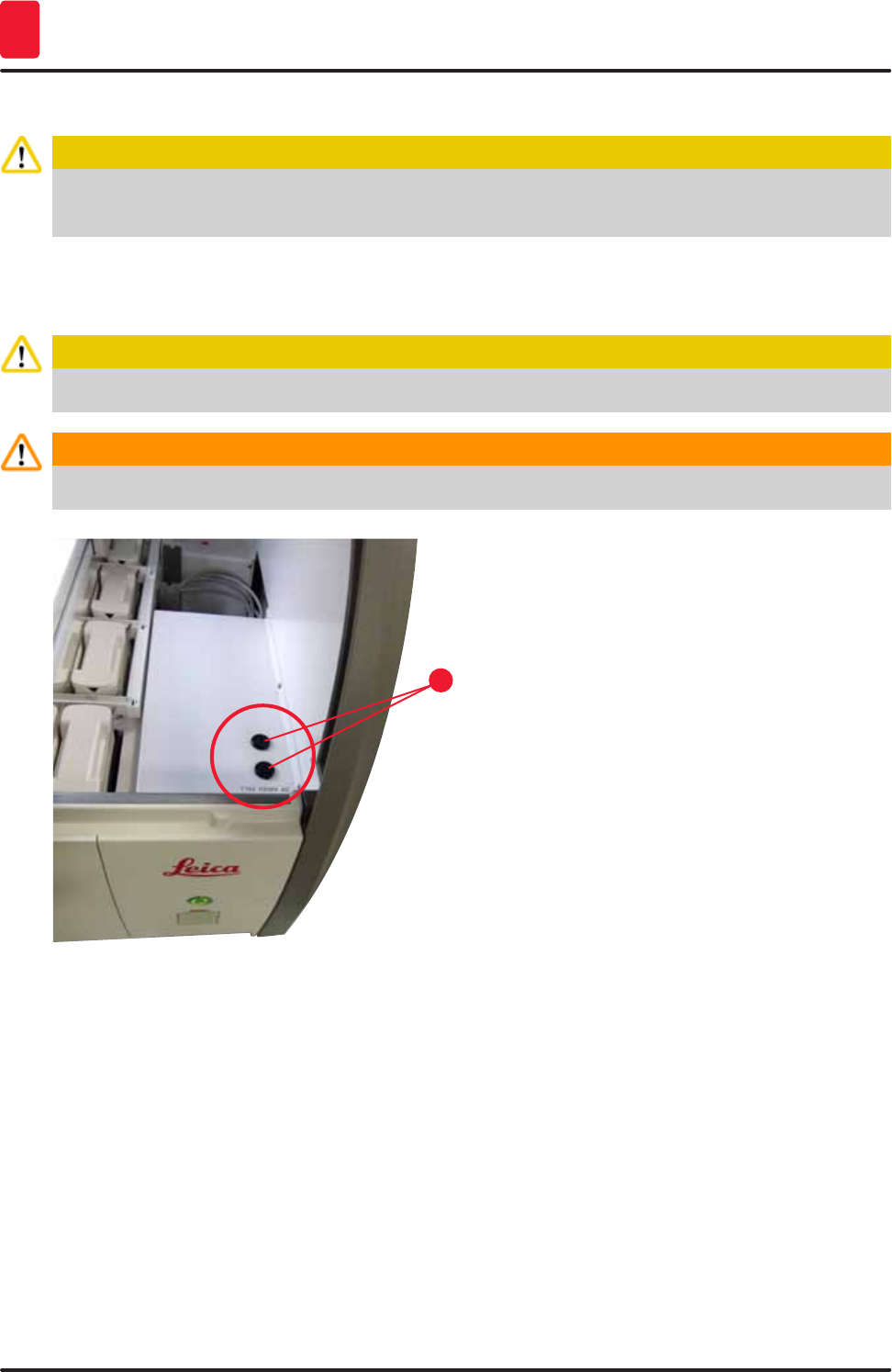
132 Version 1.3, Revision J
Malfunctions and Troubleshooting
8
8.3 Replacing main fuses
Caution
The instrument should be switched off using the main switch and disconnected from the power supply
in the case of a instrument failure. The main fuses can then be inspected.
• To do so, open the hood and unscrew the two fuse holders on the top of the right cover
(→ "Fig. 116-1") with a flat-head screwdriver and check for damage.
Caution
A suitable flat-head screwdriver must be used to prevent damage to the fuse holder.
Warning
Beware of defective fuses! Potential risk of injury due to broken glass!
1
Fig. 116
• If the fuse is defective, remove it from the fuse holder and replace it with a new fuse (→ p. 19 – 3.1
Standard delivery).
• Installation occurs in the reverse sequence of operations.
8.4 Remote Care
A Leica service technician can use Remote Care to remotely monitor, access and repair products that
are in use at the user's location.
If the instrument is connected to Remote Care (→ p. 55 – 5.7.10 Network settings) and a malfunction
occurs, Leica Service can access the screen directly after permission from the user.
• To do so, contact the Leica Service team and let it know about the malfunction.
• The Leica service technician now accesses the instrument via Remote Care.
• The user is informed by a message on the screen and approves access to the instrument by
confirming the message.
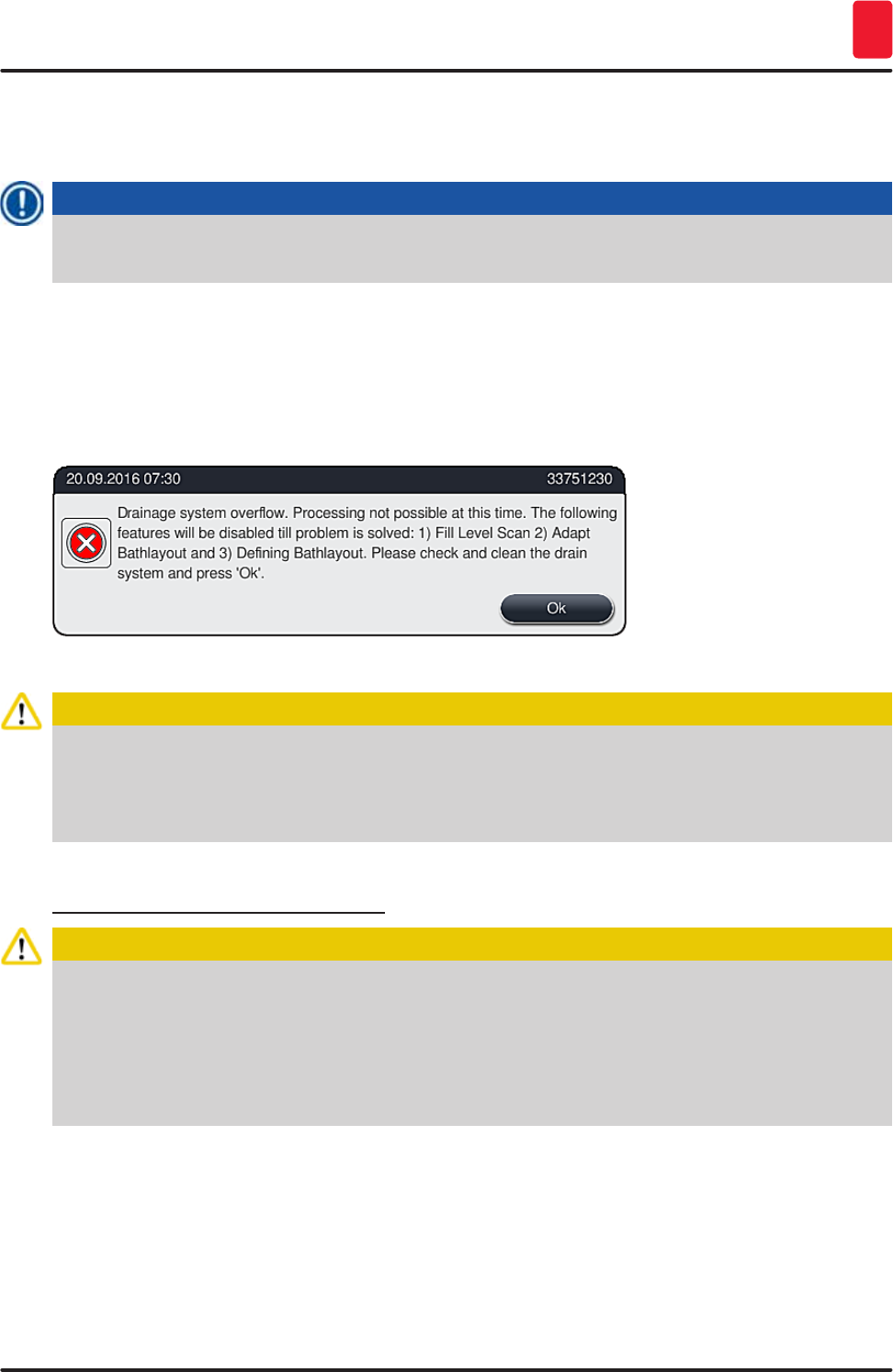
133
HistoCore SPECTRA ST
Malfunctions and Troubleshooting 8
• The Leica service technician attempts to remedy the malfunction together with the user.
• At the end of remote access, Remote Care is disconnected again by the user (→ "Fig. 17-4") or by the
Leica service technician.
Note
The user can disconnect an active Remote Care connection for service purposes at any time by
pressing the connection symbol (→ "Fig. 17-4").
8.5 Water drain system blocked
Water drain system blockage (in the drainage sieve (→ "Fig. 97-1") or in the drain hose (→ "Fig. 8-1")
can lead to rising water levels in the drain pan. As a result, a critical water level can be reached in the
instrument. The user receives an error message (→ "Fig. 117") on the screen and an alarm sounds.
Fig. 117
Caution
Losses in quality and delays in the staining process can occur in the event of a critical rising water
level in the instrument resulting from a water drainage system blockage. Ongoing staining programs
are temporarily stopped. The blockage is to be remedied immediately by the user as described
below.
Removing a water drain system blockage
Caution
• If racks are still located in the rinsing water vessels, they are to be removed and stored
temporarily in water outside of the instrument.
• Write down the position of the removed rack to ensure that the staining process can be resumed
again after removing the blockage.
• The neighboring reagent vessels are to be covered for protection and can remain in the
instrument for the time being.
1. Open the instrument cover if the warning message appears (→ "Fig. 117").
2. Carefully remove the rinsing water and, if necessary, the neighboring reagent vessels over the
drainage sieve (→ p. 113 – 7.12 Water drainage).
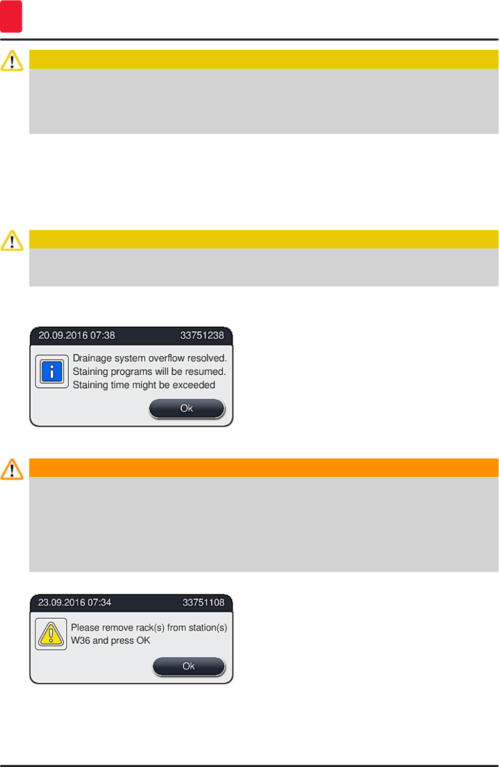
134 Version 1.3, Revision J
Malfunctions and Troubleshooting
8
Caution
Be careful when removing the rinsing water vessels. Lift each individual rinsing water vessel
and allow the water inside of it to run into the drain pan. In order to remove the vessels from
the instrument without having water drip into the reagent vessel, it is necessary to drain them
completely.
3. Check the drainage sieve and the curved drainage in the inside of the instrument (→ "Fig. 97-2")
for clogs and clean them as described in (→ p. 113 – 7.12 Water drainage) and (→ p. 114 –
7.13 Water drain hose), if necessary.
4. If the blocked water drains, the previously removed rinsing water vessels, reagent vessels and
racks can be placed back on their original positions.
Caution
Please note that the covers of previously covered reagent vessels must be removed before closing
the instrument cover again.
5. Close the instrument cover and confirm the message (→ "Fig. 118") by pressing "OK".
Fig. 118
Warning
If the blockage cannot be removed by the user and if the water level in the drain pan remains at
a critical level, all racks must be removed from the instrument. The report (→ "Fig. 119") on the
screen regarding the removal of the rack must be observed. This message appears after closing the
instrument cover, after the instrument has identified that the blockage cannot be removed.
It is to be noted that the programs are no longer bootable and the responsible Leica service
organization is to be notified.
Fig. 119
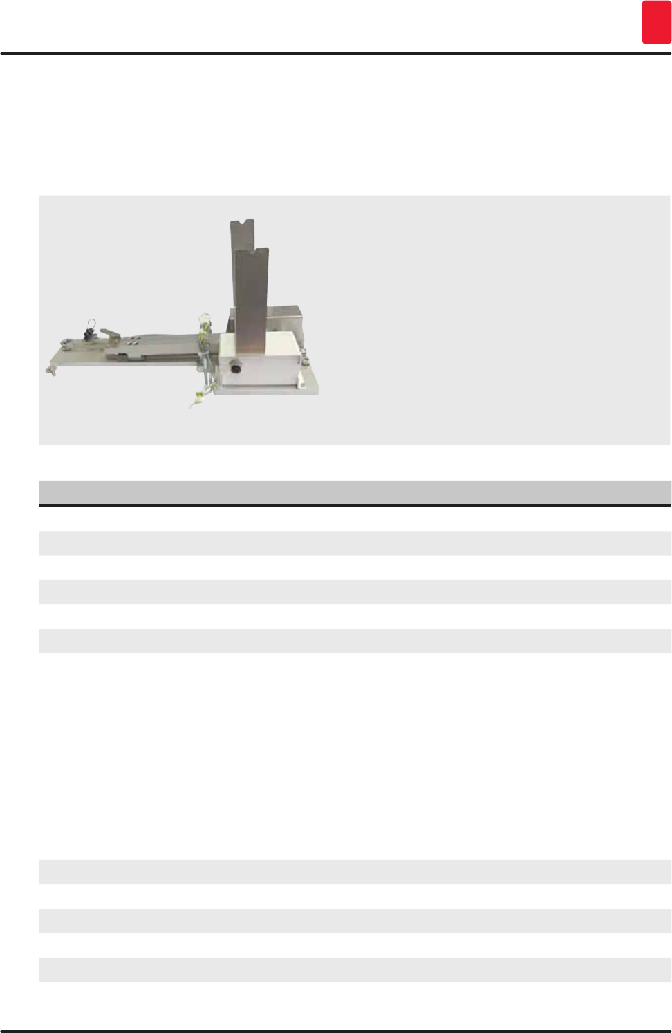
135
HistoCore SPECTRA ST
Instrument Components and Specifications 9
9. Instrument Components and Specifications
9.1 Optional instrument components
Fig. 121
Transfer module for racks
For use in the HistoCore SPECTRA ST, for
transferring samples to a connected robotic
coverslipper HistoCore SPECTRA CV.
This module is required when integrating a
robotic coverslipper HistoCore SPECTRA CV to
a workstation. It transfers the specimen slide
automatically from the HistoCore SPECTRA ST
staining machine into the HistoCore SPECTRA CV
robotic coverslipper.
Order No. 14 0512 47395
9.2 Optional accessories
Designation Order No.
Exhaust hose, 2 m 14 0512 54365
Active carbon filter set (2 pcs.) 14 0512 53772
Replacement filter for oven air filter (3 pieces) 14 0512 54943
Outlet hose, 2 m 14 0512 55279
Supply hose 14 0474 32325
Reagent vessel, assembly, including reagent vessel cover 14 0512 47086
Water connection kit with filter, consisting of:
2 pc. supply hoses, 10 mm, 2.5 m
1 pc. pressure hose 3, 1.5 m extension
1 pc. Y-piece G3/4
1 pc. double nipple G3/4 G3/8
1 pc. filter housing
1 pc. filter cartridge
1 pc. bushing G3/4
1 pc. blind cap G3/4
1 pc. gasket
1 pc. single-head wrench SW30 DIN894
14 0512 49324
14 0474 32325
14 0512 49334
14 3000 00351
14 3000 00350
14 0512 49331
14 0512 49332
14 3000 00360
14 3000 00434
14 0512 54772
14 0330 54755
Transfer module for racks 14 0512 47395
Insert for special dyes 14 0512 49261
Rinsing water vessel, blue, assembly 14 0512 47087
Molykote 111 grease, 100 g 14 0336 35460

136 Version 1.3, Revision J
Instrument Components and Specifications
9
Designation Order No.
Set of label covers for the input and output drawers
(10 blank, 5 each of "H2O"=water, "A"=alcohol and "S"=solvent, e.g. xylene)
14 0512 55161
O-rings 7x2, for rinsing water vessel connecting piece (12 pcs. per package) 14 0253 54716
Rack for 30 specimen slides* (3 pcs. per package) 14 0512 52473
Rack 5 specimen slides* (3 pcs. per package) 14 0512 52475
Handle for rack for 30 specimen slides* (yellow, 3 pcs. per package) 14 0512 52476
Handle for rack for 30 specimen slides* (light blue, 3 pcs. per package) 14 0512 52477
Handle for rack for 30 specimen slides* (dark blue, 3 pcs. per package) 14 0512 52478
Handle for rack for 30 specimen slides* (pink, 3 pcs. per package) 14 0512 52479
Handle for rack for 30 specimen slides* (red, 3 pcs. per package) 14 0512 52480
Handle for rack for 30 specimen slides* (light green, 3 pcs. per package) 14 0512 52481
Handle for rack for 30 specimen slides* (black, 3 pcs. per package) 14 0512 52482
Handle for rack for 30 specimen slides* (gray, 3 pcs. per package) 14 0512 52483
Handle for rack for 30 specimen slides* (white, 3 pcs. per package) 14 0512 52484
Handle for rack 5 specimen slides* (yellow, 3 pcs. per package) 14 0512 52494
Handle for rack 5 specimen slides* (light blue, 3 pcs. per package) 14 0512 52495
Handle for rack 5 specimen slides* (dark blue, 3 pcs. per package) 14 0512 52496
Handle for rack 5 specimen slides* (pink, 3 pcs. per package) 14 0512 52497
Handle for rack 5 specimen slides* (red, 3 pcs. per package) 14 0512 52498
Handle for rack 5 specimen slides* (light green, 3 pcs. per package) 14 0512 52499
Handle for rack 5 specimen slides* (black, 3 pcs. per package) 14 0512 52500
Handle for rack 5 specimen slides* (gray, 3 pcs. per package) 14 0512 52501
Handle for rack 5 specimen slides* (white, 3 pcs. per package) 14 0512 52502
Note
• Information about the available Leica reagent kits and validated Leica programs can be
requested from the responsible Leica sales organization.
• Furthermore, instructions for use is provided with each Leica reagents kit, in which a supply
source is specified for the import of validated Leica programs.
Fig. 122
Outlet hose
Length: 2 m
Order No. 14 0512 55279
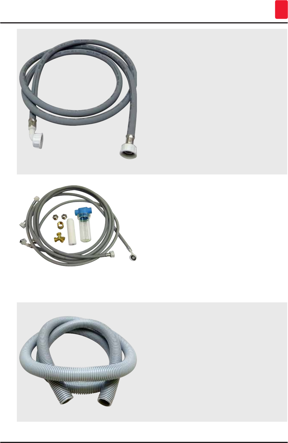
137
HistoCore SPECTRA ST
Instrument Components and Specifications 9
Fig. 123
Supply hose for rinsing water
Length: 2.50 m assembly with 3/4" connection for
water tap, incl. replacement seal
Order No. 14 0474 32325
Fig. 124
Water connection kit with filter
Order No. 14 0512 49324
Consisting of:
Supply hose, 10 mm, 2.5 m 14 0474 32325
Extension hose, 1.5 m 14 0512 49334
Y-piece G3/4 14 3000 00351
2x G3/4 G3/8 double nipple 14 3000 00350
Water filter housing 14 0512 49331
Filter cartridge 14 0512 49332
Bushing G3/4 14 3000 00360
Blind cap G3/4 14 3000 00434
Gasket 14 0512 54772
Single-head wrench
SW30 DIN894 14 0330 54755
Fig. 125
Exhaust hose
Length: 2 m
Order No. 14 0512 54365
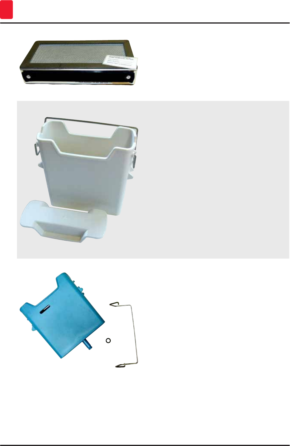
138 Version 1.3, Revision J
Instrument Components and Specifications
9
Fig. 126
Active carbon filter
1 set, consisting of 2 pcs.
Order No. 14 0512 53772
Fig. 127
Reagent vessel
Assembly, incl. reagent vessel cover
Order No. 14 0512 47086
Fig. 128
Rinsing water vessel
assembly
Order No. 14 0512 47087
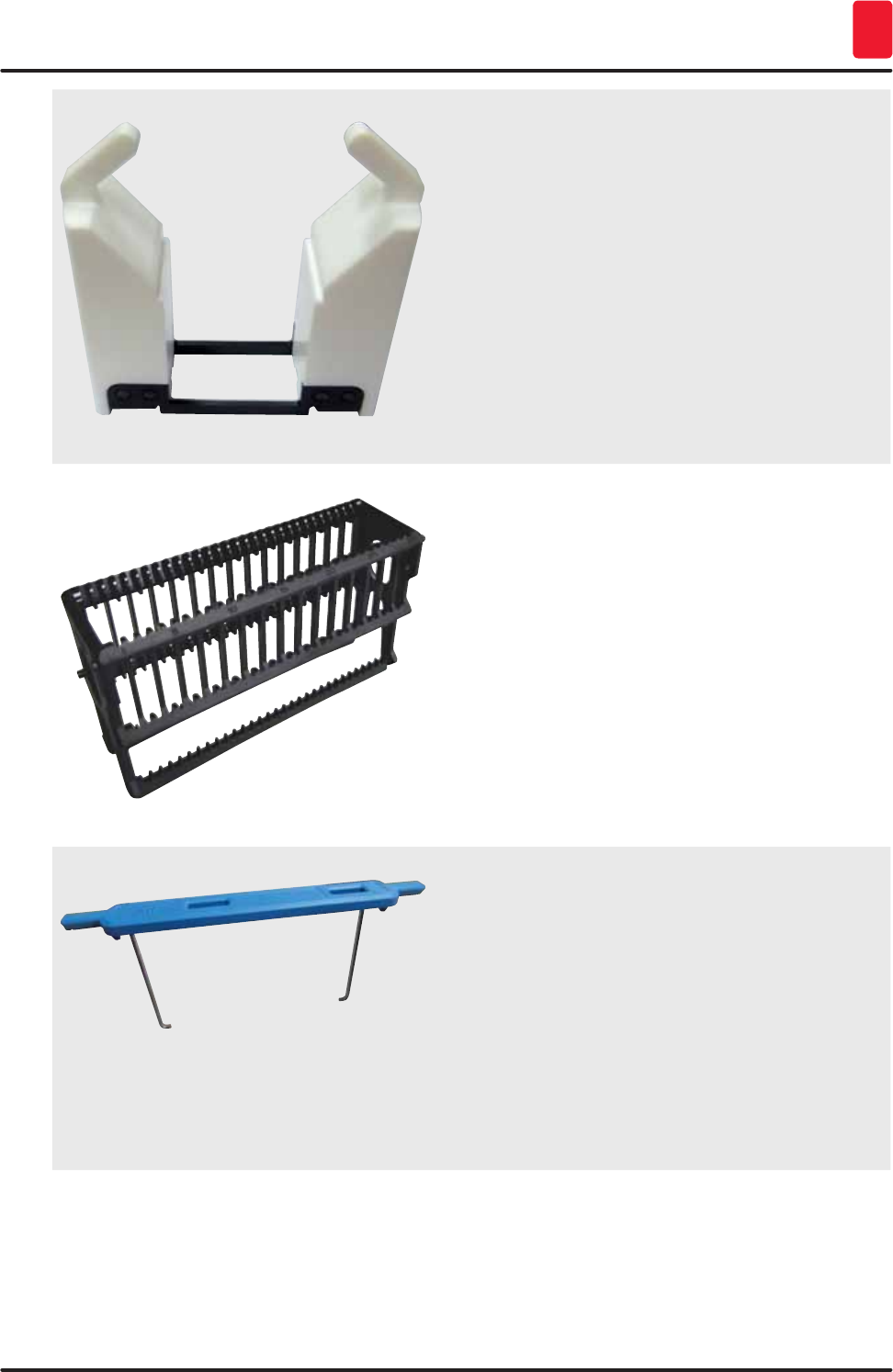
139
HistoCore SPECTRA ST
Instrument Components and Specifications 9
Fig. 129
Insert for special dyes
(only for racks designed for up to 5 specimen
slides)
Order No. 14 0512 49261
Fig. 130
Racks
30 specimen slides, (3 pcs. per package)
Order No. 14 0512 52473
Fig. 131
Handle for rack
30 specimen slides, (3 pcs. per package)
Color Order No.:
yellow 14 0512 52476
light blue 14 0512 52477
dark blue 14 0512 52478
pink 14 0512 52479
red 14 0512 52480
light green 14 0512 52481
black 14 0512 52482
gray 14 0512 52483
white 14 0512 52484
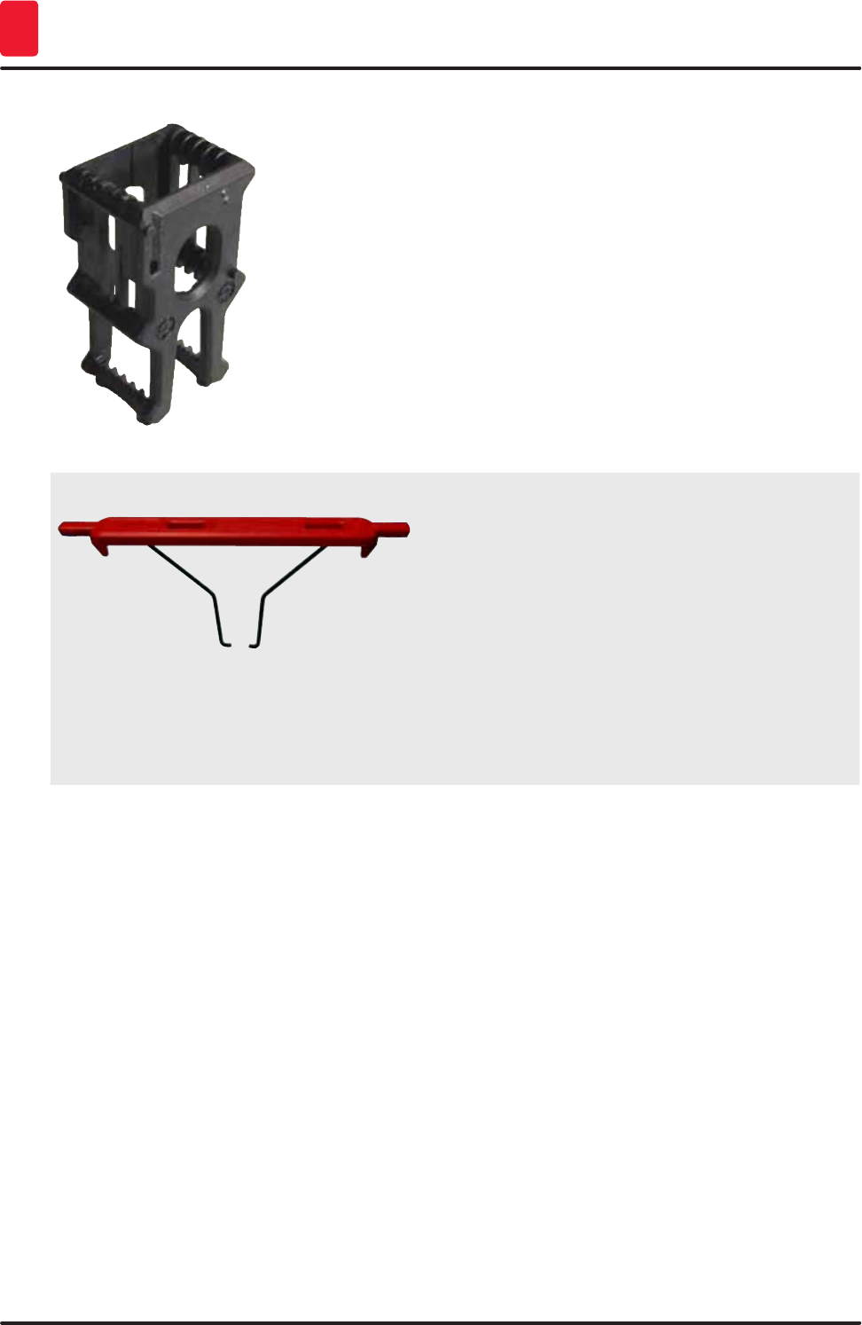
140 Version 1.3, Revision J
Instrument Components and Specifications
9
Fig. 132
Racks
5 specimen slides, (3 pcs. per package)
Order No. 14 0512 52475
Fig. 133
Handle for rack
5 specimen slides, (3 pcs. per package)
Color Order No.:
yellow 14 0512 52494
light blue 14 0512 52495
dark blue 14 0512 52496
pink 14 0512 52497
red 14 0512 52498
light green 14 0512 52499
black 14 0512 52500
gray 14 0512 52501
white 14 0512 52502

141
HistoCore SPECTRA ST
Warranty and Service 10
10. Warranty and Service
Warranty
Leica Biosystems Nussloch GmbH guarantees that the contractual product delivered has been
subjected to a comprehensive quality control procedure based on the Leica in-house testing standards,
and that the product is faultless and reflects all technical specifications and/or agreed characteristics.
The scope of the warranty is based on the content of the concluded agreement. The warranty terms
of your Leica sales organization or the organization from which you have purchased the contractual
product shall apply exclusively.
Service information
If you are in need of technical customer support or spare parts, please contact your Leica
representative or the Leica dealer where you purchased the instrument.
Please provide the following information on the instrument:
• Model name and serial number of the instrument.
• Location of the instrument and name of a contact person.
• Reason for the service call.
• The delivery date of the instrument.
142 Version 1.3, Revision J
Decommissioning and disposal
11
11. Decommissioning and disposal
Caution
The instrument or parts of the instrument must be disposed of according to existing applicable,
local regulations. All objects contaminated with spilled reagents must be disinfected immediately
with a suitable disinfectant to prevent spreading to other areas of the lab or to lab personnel.
Please refer to the (→ p. 108 – 7. Cleaning and Maintenance) Chapter as well as the Decontamination
Confirmation (→ p. 143 – 12. Decontamination Confirmation) Chapter at the end of these Instructions
for Use in order to find information about cleaning the HistoCore SPECTRA ST stainer.
The instrument can be contaminated when using biohazardous specimens. Thorough disinfecting is
required before re-commissioning or disposal (e.g. multiple cleaning steps, disinfection or sterilization).
Dispose of the instrument in compliance with the applicable laboratory specifications.
Contact your Leica representative for more information.
Instrument components such as the computer, monitor, etc. that are labeled
with the crossed-out dust bin are affected by the European Directive 2002/96/
EC for Waste Electrical and Electronic Equipment (WEEE) of the European
Parliament and the Council of January 27, 2003.
These objects must be disposed of via the collection points in accordance with
the local regulations. More information on disposal of the instrument can be
obtained from your local disposal company or your local Leica support staff.

143
HistoCore SPECTRA ST
Decontamination Confirmation 12
12. Decontamination Confirmation
Every product that is returned to Leica Biosystems or that requires on-site maintenance must be
properly cleaned and decontaminated. You can find the dedicated template of the decontamination
confirmation on our website www.LeicaBiosystems.com within the product menu. This template has to
be used for gathering all required data.
When returning a product, a copy of the filled and signed confirmation has to be enclosed or passed on
to the service technician. The responsibility for products that are sent back without this confirmation
or with an incomplete confirmation lies with the sender. Returned goods that are considered to be a
potential source of danger by the company will be sent back at the expense and risk of the sender.
144 Version 1.3, Revision J
Appendix
Appendix 1 - Compatible reagents
Caution
• Using non-listed reagents (e.g. acetone or solutions containing phenol) or reagents and acids
in higher concentration than described can cause specimens to be destroyed, operators to be
injured or the instrument to be damaged. Use the instrument in this way at your own risk. Leica
Biosystems or affiliated sales and service organizations shall not assume any warranty claims
or liability.
• Flammable reagents and solvents must not be heated for fire and explosion protection reasons.
Keep away all ignition sources when handling flammable solvents and reagents.
Note
All Leica reagents for preinstalled Leica programs have been tested with the instrument for staining
quality and compatibility of materials.
Staining method or reagent group Reagent name Notes
H&E kit Leica Infinity ST Hemalast
ST Hematoxylin
ST Differentiator
ST Bluing
ST Eosin
Leica SelecTech Hemotoxylin 560
Hemotoxylin 560MX
Define MX-aq
Blue Buffer-8
Y515 Alcoholic Eosin
Y515LT Alcoholic Eosin
515 Eosin Trichrome
Eosin Phloxine
Other H&E
reagents
Leica Gill II Hematoxylin
Gill III Hematoxylin
Harris Hematoxylin
Mayer's Hemalaun
Leica Alcoholic Eosin
Aqueous Eosin (1 %)
Leica Scott's Tap Water Solution
Leica Acid Alcohol 0.5 %
Leica Acid Alcohol 1.0 %
User-defined Hydrochloric Acid 2 %
PAS Leica Periodic Acid 0.5 %
User-defined Periodic Acid (up to 10 %)
Leica Schiff's Reagent
Diastase-PAS Leica Diastase solution (37 °C)

145
HistoCore SPECTRA ST
Appendix
Staining method or reagent group Reagent name Notes
Alcian Blue-PAS Leica Alcian Blue-Solution
Alcian Blue Leica
Alcian Blue and
other Staining
Methods
Leica Nuclear fast Red
Gomori Trichrome
Blue and Green
Collagen Staining
Leica Weigert Hematoxylin (A+B
Solution)
Gomori Trichrome Blue Stain
1 % Acetic Acid
Light green
Perl's Iron
Staining
Leica Potassium ferrocyanide
solution
Hydrochloride Acid Solution
• Must not come into
contact with metal ions
• Only for use with coated
5 series rack handles
Giemsa Leica Methanol Solution A
Stain 1 Solution B
Stain 2 Solution C
Buffer Solution D
Congo Red
Amyloid Stain
Leica Congo Red Solution
Leica 1 % Potassium Hydroxide
Solution
User-defined Saturated Lithium Carbonate
Solution
Alcian Yellow
for Helicobacter
Pylori
Leica Alcian Yellow-Solution (0.25 %
Alcian Yellow)
5 % Periodic Acid
5 % Sodium Metabisulfite
6.8 pH Sorensen Buffer
Toluidin Blue Solution
Elastic Stain/
Verhoeff's van
Gieson
Leica 5 % Alcoholic Hematoxylin
10 % Ferric Chloride
Lugol's Iodin Solution
2 % Ferric Chloride
Verhoeff's Staining Solution
Van Gieson's Stain
146 Version 1.3, Revision J
Appendix
Staining method or reagent group Reagent name Notes
Gomori
Methenamine
Silver Stain
Leica Modified Chromic Acid (up to
5 %)
Methenamine Borax
0.5 % Silver Nitrate
1 % Sodium Bisulfate
1 % Gold Chloride
2 % Sodium Thiosulfate
Light green
•
• Must not come into
contact with metal ions
• Only for use with coated
5 series rack handles
Papanicolaou
(PAP)
Leica EA-50
Leica Orange G-6
Leica EA-65 (Secondary Counter
Stain)
Schmorl's
Reduction
Schmorl's Solution • Only for use with coated
5 series rack handles
(Müller) Colloidal
Iron
Colloidal Iron Solution
Ferrocyanide-Hydrochloric
Acid Solution
• Only for use with coated
5 series rack handles
Other reagents User-defined Anilin Blue
User-defined Methylene Blue
User-defined Fast Green
User-defined Carmin
User-defined Southgate or Mayer's
Micicarmine
User-defined Neutral Red
User-defined Safranin
147
HistoCore SPECTRA ST
Appendix
Staining method or reagent group Reagent name Notes
Solvent Leica/user-defined Xylene, Toluene
Leica Leica Ultra ST Xylene Substitute based on
Alipahtic Hydrocarbons
Leica Leica Clearene Limonene based Xylene
Substitute
Merck Merck Neo-Clear Xylene Substitute based on
Alipahtic Hydrocarbons
Carl Roth Roti®-Histol Limonene based Xylene
Substitute
Richard-Allen
Scientific/Thermo
Scientific
Clear-Rite 3 Xylene Substitute based on
Alipahtic Hydrocarbons
Richard-Allen
Scientific/Thermo
Scientific
Citrus Clearing Solvent Limonene based Xylene
Substitute
Alcohol Leica/user-defined 2-Propanol (Isopropanol)
Leica/user-defined Ethanol
Methanol
Richard-Allen
Scientific/Thermo
Scientific
Dehydrant Ethyl Alcohol, Methyl
Alcohol
Richard-Allen
Scientific/Thermo
Scientific
Flex Isopropyl, Alcohol, Methyl
Alcohol
Usual Acids (Max.
Concentration)
User-defined Acetic Acid (up to 15 %)
Hydrochloric Acid (up to 5 %)
Piric Acid (up to 3 %)

148 Version 1.3, Revision J
Notes