Leica TPS400 400mining01 User Manual To The Be1eacb5 F267 4322 9174 3f6d86e23b2b
User Manual: Leica TPS400 to the manual
Open the PDF directly: View PDF ![]() .
.
Page Count: 36

User Manual Mining Application Program
English
Version 1.0
TPS400 Series

TPS400 Mining Manual-1.0.0en 2
To use equipment in the permitted manner, please refer to the
detailed safety instructions in the TPS400 User Manual (English
version).
The quick way to start with the TPS400 Mining Programs.
The quick way to start
© 2003 Leica Geosystems AG Heerbrugg, ® All rights reserved.

TPS400 Mining Manual-1.0.0en 3
Contents - Overview
Contents - Overview
Introduction ......................................................................... 5
Peg Survey .......................................................................... 6
Front Line Peg .................................................................. 16
Grades................................................................................ 17
Offset.................................................................................. 23
Setting out ......................................................................... 27
Tie Distance....................................................................... 29
Mining Editor ..................................................................... 31

TPS400 Mining Manual-1.0.0en 4
Contents
Introduction ................................................ 5
How to use this manual ............................... 5
Symbols used in the sequence
of operation .................................................. 5
Peg Survey ................................................. 6
Introduction .................................................. 6
Before starting Peg Survey .......................... 7
Start and execution Peg Survey ................... 8
Error messages ........................................... 9
Proceeding Peg Survey ............................. 10
Results ....................................................... 13
Saving data ................................................ 15
Front Line Peg.......................................... 16
Introduction ................................................ 16
Grades....................................................... 17
Introduction ................................................ 17
Start and execution Grades ....................... 18
Gradeline Marking ...................................... 20
Results ....................................................... 21
Saving data ................................................ 22
Contents
Offset......................................................... 23
Introduction ................................................ 23
Start and execution Offset ......................... 24
Results ....................................................... 26
Setting out ................................................ 27
Polar setout ............................................... 27
Orthogonal setout ...................................... 28
Cartesian setout ........................................ 28
Tie Distance.............................................. 29
Mining Editor ............................................ 31
Introduction ................................................ 31
Installation on the PC ................................. 31
Program content ........................................ 31
Practical Examples .................................... 32
First Example (Creating fixpoint files,
define tolerances, uploading) ..................... 33
Second Example (Importing of fixpoints
in ASCII format) ......................................... 35
TPS400 Mining Manual-1.0.0en Introduction
5
Introduction
How to use this manual
This manual describes the basic
operation of the TPS400 Mining
field programs. It shall be used
together with a TPS400
instrument.
For detailed description about
the whole functionality of the
TPS400 instrument please refer
to the TPS400 User Manual.
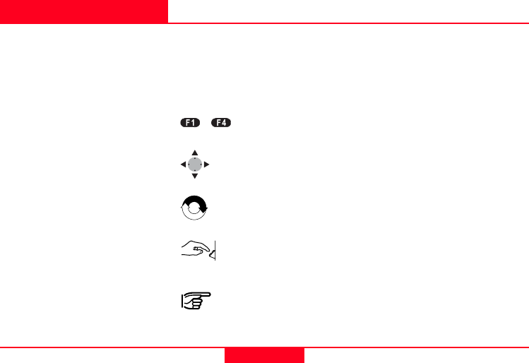
Symbols used in the sequence of operation
Press the [MENU] button
Press the function button [F1-F4]
Navigation keys
Repeat operation
User input is necessary
Important paragraphs which must be adhered to in
practice as they enable the product to be used in a
technically correct and efficient manner.
[MENU]
-
TPS400 Mining Manual-1.0.0en Peg Survey
6
Peg Survey
Mining_z01
Introduction
The application "Peg Survey" is
used to establish a forward peg
(point). It is used to control the
intermediate horizontal angle
between backsight and foresight
points. It also checks the
horizontal distances and heights
of the backsight and foresight
points. It computes the
coordinates of the foresight
point. "Peg Survey" allows users
to measure several sets in
different sequences. (The
quality of measurement is
controlled by the tolerances
which are set before starting
"Peg Survey").
Known:
• Coordinates of station
• Coordinates of backsight
point
Unknown:
• Coordinates of foresight point
-hr
-hi
-hr
Hz=0°00'00"
Backsight Point Station Foresight Point
Hz2
Hz1
Dist2
Dist1
TPS400 Mining Manual-1.0.0en Peg Survey
7
Before starting Peg Survey
Data uploading using "Mining
Editor"
• Station coordinates
(East, North, Height,
Grade elevation)
• Backsight point coordinates
(East, North, Height,
Grade elevation)
• Tolerances, sequence,
number of sets
• Job definition
Uploading of fixpoint
coordinates, tolerances,
sequence and number
of sets is mandatory to
enable the operation of
"Peg Survey".
To create new jobs on
board the instrument, a
set of tolerance must be
available.
TPS400 Mining Manual-1.0.0en Peg Survey
8
Start and execution Peg Survey
> Step 3 Choose "Start" by
pressing [F4], then
enter point number
(PtID) and
instrument height
(hi) for the station.
The sign for the
instrument height
(hi) is normally
negative.
> Step 4 [SET]
Set Point number
(PtID) and
instrument height
(hi).
[EXIT] Leaves "Input
Station" and returns
to the start-up menu.
• Press [MENU] and [F1] for
programs.
• Press [F1] for Peg Survey.
> Step 1 Select a job.
> Step 2 Confirm the set of
tolerances.
TPS400 Mining Manual-1.0.0en Peg Survey
9
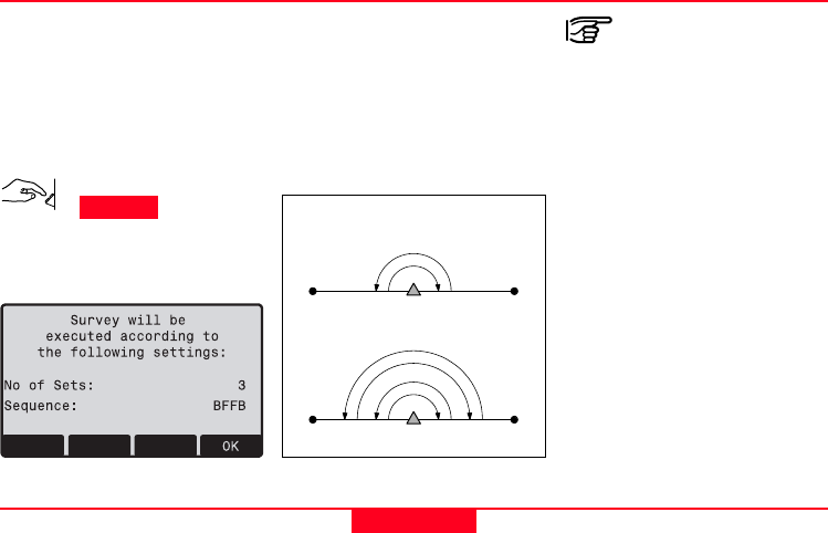
Error messages
Number of sets:
One set means to measure two
times the backsight point and
two times the foresight point in
both faces.
The meaning of set is
described:
Mining_z02
One Set
The user must complete
the number of sets as
preset in the tolerance
setting.
FSBS
Two Sets
I Set
FSBS
I Set
II Set
Station or BS point has no
valid coords !
• The point number entered is
not available in the internal
memory or it has invalid
coordinates.
Re-enter point number
( > Step 3 ).
Sample dialog:
TPS400 Mining Manual-1.0.0en Peg Survey
10
Sequence:
It defines the measuring
sequence.
Options:
•BFFB
Backsight-Foresight-
Foresight-Backsight
•BFBF
Backsight-Foresight-
Backsight-Foresight
•BBFF
Backsight-Backsight-
Foresight-Foresight
[OK] Leaves this dialog
and proceed to the
next dialog.
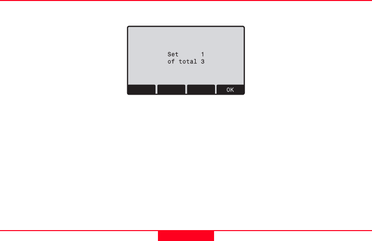
Proceeding Peg Survey
Sample dialog:
Set 1 of total 3
Start with measurement first set
of three.
[OK] Leaves this dialog
and proceed to the
next dialog.
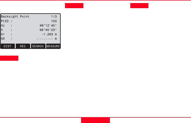
Measure Backsight Point
Information about which
backsight point the user has to
measure.
[OK] Leaves this dialog
and proceed to the
measure dialog.
TPS400 Mining Manual-1.0.0en Peg Survey
11
Proceeding Peg Survey, continued
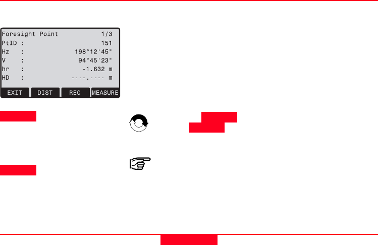
> Step 7 Enter a desired
foresight point
number (PtID).
[OK] Saves the foresight
point number and
proceed to the
measure dialog.
Sample dialog:
> Step 5 Enter the reflector
height (hr) for the
backsight point, if
required.
> Step 6 Aim at backsight
point and measure.
[MEASURE] or [DIST]/[REC]
Angle and distance
measurements are
triggered and stored
in the internal
memory.
[SEARCH] Allows users to
search and choose a
different backsight
point.
[EXIT] Terminates the
program and returns
to the start-up menu.
TPS400 Mining Manual-1.0.0en Peg Survey
12
Proceeding Peg Survey, continued
[REJECT] Reject the
measurement and
measure the set
again.
[ACCEPT] Accept the result
and continue with
the next set.
Sample dialog:
> Step 8 Enter the reflector
height (hr) for the
foresight point, if
required.
> Step 9 Aim at foresight
point and measure.
[MEASURE] or [DIST]/[REC]
Angle and distance
measurements are
triggered and stored
in the internal
memory.
[EXIT] Terminates the
program and returns
to the start-up menu.
Repeat > Step 6
and > Step 9 until
all sets are
measured.
If the tolerances
after a set are not
met, the user has
the option to
continue with the
measuring or
rejecting the data.
TPS400 Mining Manual-1.0.0en Peg Survey
13
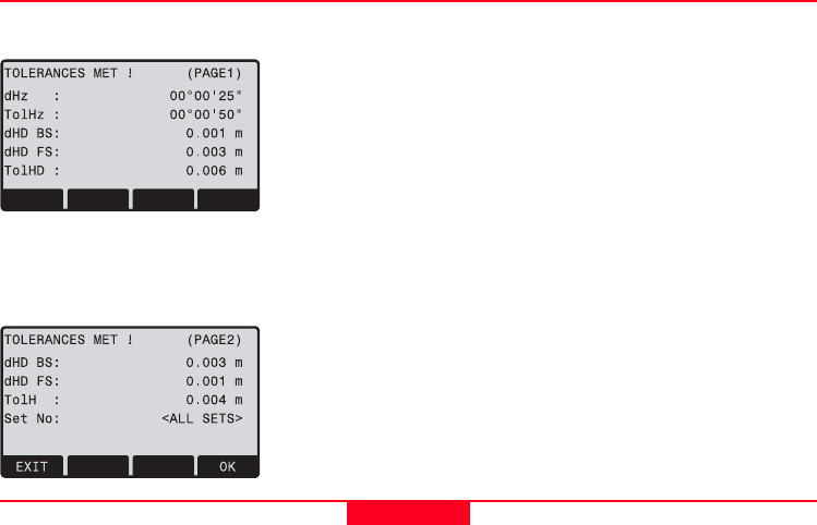
Results
Sample dialog: Tolerances dialog:
• dHz: Residual on the
horizontal angle
• dHD: Residual on the
horizontal distance
• dH: Height residual
• TolHz, TolHD, TolH:
Tolerances horizon-
tal angle, horizontal
distance and height
• Set No: Set number
[PAGE]
Sample dialog:
[OK] Leaves this dialog
and proceed to the
result dialog.
[EXIT] Terminates the
measurement and
returns to the start-
up menu.
TPS400 Mining Manual-1.0.0en Peg Survey
14
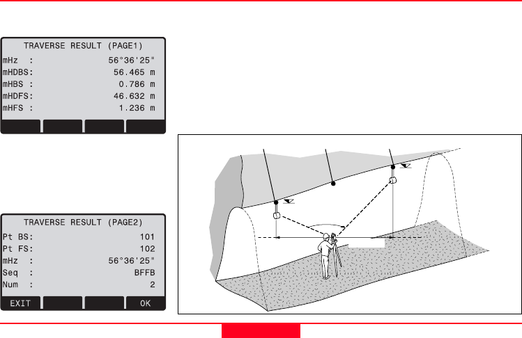
Results, continued
Sample dialog:
[PAGE]
Sample dialog:
Result dialog:
•mHz: Average
intermediate horizontal angle
between backsight point and
foresight point
• mHDBS/FS: Average
horizontal distance
(Backsight and Foresight)
• mHBS/FS: Average height
(Backsight and Foresight)
•Pt BS/FS: Point number
(Backsight and Foresight)
•Seq: Sequence
•Num: Number of sets
Mining_z03
mHBS
mHFS
mHz
mHDBS mHDFS
Backsight Point Station Foresight Point

TPS400 Mining Manual-1.0.0en Peg Survey
15
Results, continued
[OK] Quits the program.
[EXIT] Terminates the
measurement and
returns to the start-
up menu.
The following result data are
stored in the internal memory:
Result:
mHz: Average
intermediate
horizontal angle
between backsight
point and foresight
point
mHD: Average horizontal
distance (backsight
and foresight)
mH: Average height
(backsight and
foresight)
Saving data
Residual:
dHz: Residual on the
horizontal angle
dHD: Residual on the
horizontal distance
dH: Height residual
Coordinates foresight point:
E: Easting
N: Northing
H: Height point
GrEl: Grade Elevation

TPS400 Mining Manual-1.0.0en Front Line Peg
16
Front Line Peg
Introduction
The application "FLP" is used to
mark a new line peg (Front line
peg). This application is similar
to "Peg Survey" and there is
only one set of measurement
required.
For a more detail explanation of
"FLP", please refer to chapter
"Peg Survey".
TPS400 Mining Manual-1.0.0en Grades
17
Grades
Mining_z04
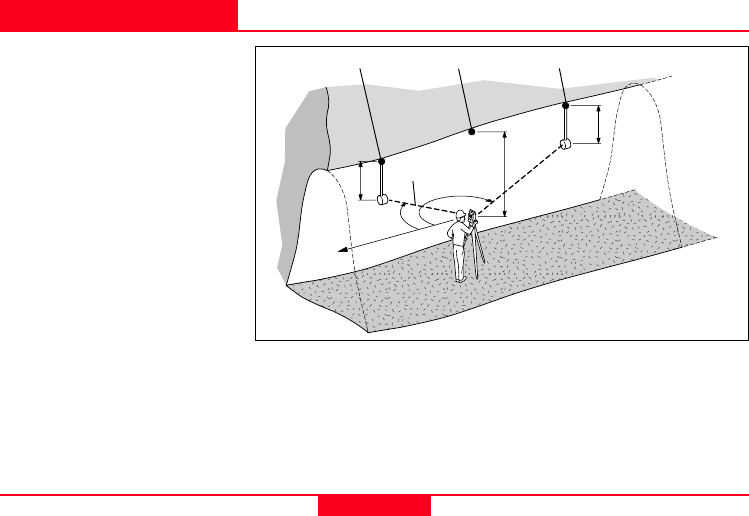
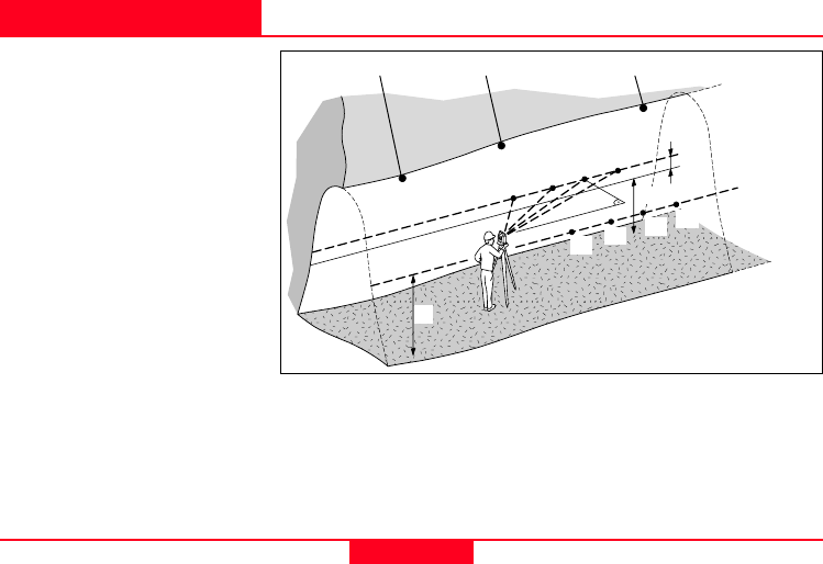
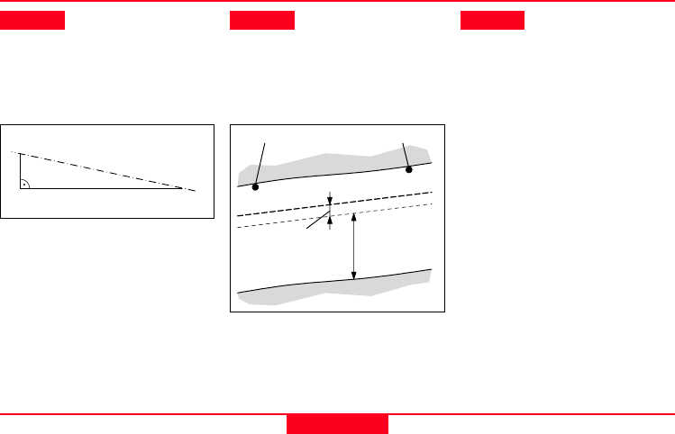
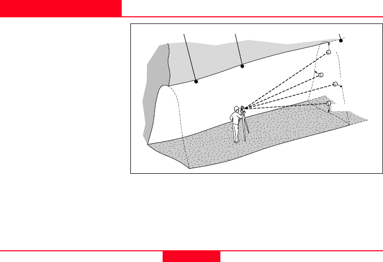
Introduction
"Grades" application is used to
mark gradelines along the side
walls of the mines (tunnels). It
allows users to input the slope
gradient and an offset
concerning the grade point. It
computes the stake out height
difference. The program allows
also to map the positions of the
grades points along the
gradelines.
Known:
• Coordinates and grade
elevation of station
• Coordinates and grade
elevation of backsight point
• Slope gradient (station until
foresight point)
• Height difference (dH)
between current gradeline
and new gradeline
Unknown:
• Stake out height difference
(dHgt) between measure
point and gradeline point
• Horizontal distance (dHD)
along the foresight line
Backsight Point Station Foresight Point
New Gradeline
dH
1234
H = Current height of
gradeline above mine floor
dH = New height difference
input for new gradeline
dHD
1A 2A 3A 4A
H
H
TPS400 Mining Manual-1.0.0en Grades
18
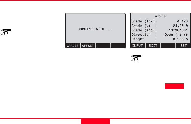
Start and execution Grades
Menu dialog of "FLP": Sample dialog:
If the slope gradient
(station until foresight
point) is the same like
the slope gradient
(backsight point until
station) then continue
direct with > Step 3 .
You can start Grades either by
selecting it in the program or
after measuring in the
application "Front Line Pag".
When you start it from
programs you have to
enter station data and
measure to back- and
foresight point first.
TPS400 Mining Manual-1.0.0en Grades
19
Mining_z06
Start and execution Peg Survey, continued
Mining_z05
150
1
H
New Gradeline
> Step 1 Enter the slope
gradient
(proportion e.g.
1:150).
Slope gradient explained:
Gradeline
> Step 2 Enter the height
difference.
Height difference explained:
H: Current height of
gradeline above
mine floor
dH: Height difference
dH
> Step 3 [SET] Set the
entered values and
proceeds to the
gradeline marking
dialog.
[EXIT] Leaves the
application "Grades"
and return to the
menu dialog of
"FLP".
Station Foresight Point
TPS400 Mining Manual-1.0.0en Grades
20
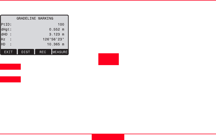
Gradeline Marking
Sample dialog:
> Step 4 Enter a desired point
number (PtID).
> Step 5 Aim at target point
and measure.
[MEASURE] or
[DIST]/[REC]
Measurement is
triggered and stored
in the internal
memory.
[PREV] Returns to the start
of "Grades"
application.
For a new definition
of slope gradient
and height
difference repeat
> Step 1 until
> Step 3 .
[EXIT] Leaves the
application "Grades"
and return to the
menu dialog of
"FLP".
TPS400 Mining Manual-1.0.0en Grades
21
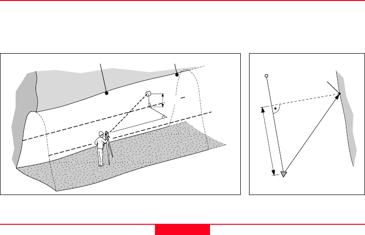
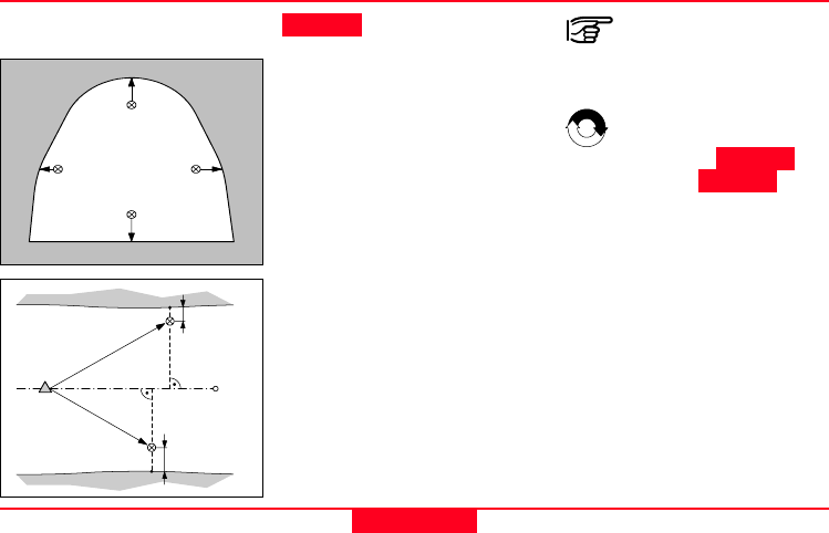
Results
Grades computes the height difference (dHgt) between measure point and stake out point and the
horizontal distance (dHD) along the foresight line.
Height difference (dHgt) and horizontal distance (dHD) explained:
Mining_z07
New
Gradeline
point
Station Foresight Point
dHD
Station
Foresight
Point
Mining_z08
Gradeline
dHgt
dHD

TPS400 Mining Manual-1.0.0en Grades
22
Results, continued Saving data
The following result data are
stored in the internal memory:
Measurement data:
PtID: Point number
Hz: Horizontal angle
V: Vertical angle
HD: Horizontal distance
SD: Slope distance
dH: Height difference
Coordinates of new gradeline
point:
E: Easting
N: Northing
H: Height
Grades Result:
daH: Stake out height
difference
daHD: Horizontal distance
along the foresight
line
Grd: Slope gradient
GE: Grade elevation
If the sign is
negative the grade
point are above the
measure point.
If the sign is positive
the grade point are
below the measure
point.
> Step 6 Turn the telescope
until the height
difference (dHgt) is
zero, then repeat the
measurement
( > Step 5 ).
TPS400 Mining Manual-1.0.0en Offset
23
Offset
Introduction
"Offset" application is generally
used to obtain sections of the
tunnels for volume computation
as well as mapping of the
tunnels. It allows users to input
offset value (left, right, up and
down) and computes after
measurement the actual
coordinates of the tunnel walls.
Known:
• Coordinates of station
• Coordinates of backsight
point
• Offset value
Unknown:
• Point coordinates of the
tunnel walls
Left
Mining_z09
Station Foresight Point
Up
Right
Down
Backsight Point
TPS400 Mining Manual-1.0.0en Offset
24
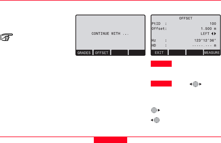
Start and execution Offset
Menu dialog of "FLP": Sample dialog:
> Step 1 Enter a desired point
number (PtID) and
the offset value.
> Step 2 Using
for the offset
definition.
(Left, Up, Right, Down)
(Left, Down, Right, Up)
You can start Offset either by
selecting it in the program or
after measuring in the
application "Front Line Pag".
When you start it from
programs you have to
enter station data and
measure to back- and
foresight point first.
TPS400 Mining Manual-1.0.0en Offset
25
Start and execution Offset, continued
Definition of offset explained:
Mining_z10
Up
Down
RightLeft
> Step 3 Aim at target point
and measure.
[MEASURE] or [DIST]/[REC]
Measurement is
triggered and stored
in the internal
memory.
[EXIT] Leaves the
application Offset
and return to the
menu dialog of "FLP".
After storing, the
program returns to
the measuring
dialog.
If you want to
measure a new point
repeat > Step 1
until > Step 3 .
Mining_z11
Offset
Right
Offset
Left
Station Foresight
Point

TPS400 Mining Manual-1.0.0en Offset
26
Results
Saving data
The following result data are
stored in the internal memory:
Measurement data:
PtID: Point number
Hz: Horizontal Angle
V: Vertical Angle
HD: Horizontal distance
SD: Slope distance
The measurement
data are already
corrected.
Offset information:
Offset: Offset value
OffsetDir: Offset direction
(left, up, right, down)
Coordinates of new offset
point:
E: Easting
N: Northing
H: Height
TPS400 Mining Manual-1.0.0en Setting out
27
Setting out
This program calculates the
required elements to stakeout
points from coordinates or
manualy entered angles,
horizontal distances and
heights. Setting out differences
can be displayed continuously.
Setting out coordinates from
memory
Procedure:
Select the point.
[DIST] Starts measurement
and calculation of
the stake-out
elements.
[REC] Saves the displayed
values.
[B&D] Input direction and
Hz-distance of stake
out point.
[MANUAL] Enables simplified
input of a point
without ptID and
without the
possibility of storing
the data of the point.
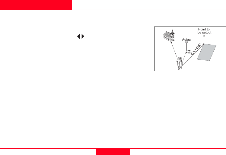
Normal indication of polar setout
offsets dHz, dHD, ddH.
dHz: Angle offset: positive
if point to be set-out
is to the right of the
actual direction.
dHD: Longitudinal offset:
positive if point to be
setout is further
away.
ddH: Height offset:
positive if point to be
setout is higher than
measured point.
Polar setout
TPS400 Mining Manual-1.0.0en Setting out
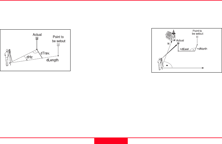
28
Orthogonal setout
The position offset between
measured point and setout point
is indicated in a longitudinal and
transversal element.
dLength: Longitudinal offset:
positive if nominal
point further away.
dTrav.: Transversal offset,
perpendicular to
line-of-sight: positive
if nominal point is to
the right of
measured point.
dHeight: Height offset:
positive if point to be
setout is higher than
measured point.
Cartesian setout
Setting out is based on a
coordinate system and the
offset is divided into a north and
east element.
dEast Easting offset
between setout and
actual point.
dNorth Northing offset
between setout and
actual point.
dHeight: Height offset:
positive if point to be
setout is higher than
measured point.
TPS400 Mining Manual-1.0.0en Tie Distance
29
Tie Distance
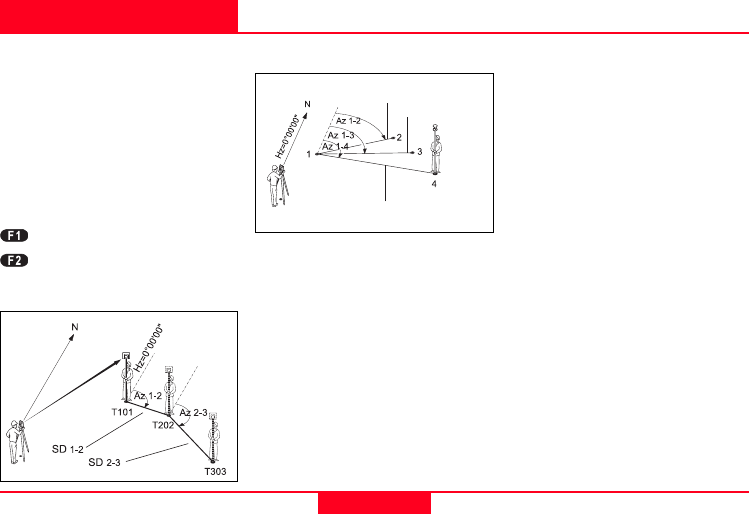
The application Tie Distance
computes slope distance,
horizontal distance, height
difference and azimuth of two
target points measured online,
selected from the Memory or
entered using the Keypad.
The user can choose between
two different methods:
Polygonal (A-B, B-C)
Radial (A-B, A-C)
Polygonal Method:
Radial Method:
In principal both methods are
the same.
Any differences will be
described.
Procedure:
1. Determine first target
point.
[ALL] Starts measurement
to the target point.
[FIND] Searches internal
memory for point
entered.
2. Determine second target
point.
Proceed as with first target
point.
3. Result is displayed.
Brg Azimuth between
point1 and point2.
dSD Slope distance
between point1 and
point2.
dHD Horizontal distance
between point1 and
point2.
ddH Height difference
between point1 and
point2.
Centre point
Slope distance 1-2
Slope distance 1-3
Slope distance 1-4

TPS400 Mining Manual-1.0.0en Tie Distance
30
Softkeys - polygonal method:
[NewPt 1] An additional
missing line is
computed. Program
starts again (at
point 1).
[NewPt 2] Point 2 is set as
starting point of a
new missing line.
New point (Pt 2)
must be measured.
[RADIAL] Switches to radial
method.
Softkeys - radial method:
[NewPt 1] Determine new
central point.
[NewPt 2] Determine new
radial point.
[POLY] Switch to poly-
gonal method.

TPS400 Mining Manual-1.0.0en Mining Editor
31
Mining Editor
Introduction
"Mining Editor" (PC Program
Package) is a Windows-based
program used for the data
exchange between the TPS400
Series and the PC.
Installation on the PC
The installation program for the
"Mining Editor" can be found on
the CD-ROM supplied. Please
note that the "Mining Editor"
program can only be installed
under the operating systems MS
Windows 95, 98, ME, NT4.0,
WINDOWS2000, XP.
For the installation call program
"setup.exe" in the directory
"MiningEditor\Disk1" on the CD-
ROM and follow the onscreen
instructions to complete the
installation.
Program content
The "Mining Editor" can be used
for the following purposes:
•Data Import & Export
Import and export fixpoint
files (ASCII format).
•Data Transfer between PC
and TPS400 instrument
Upload and download of
fixpoint files, upload of
tolerances, download of
measurement data and
conversion of measurement
data to various formats for
peg calculation and archiving.

TPS400 Mining Manual-1.0.0en Mining Editor
32
•Define and upload
Tolerances
Defining tolerances, editing
tolerances (password
protected), uploading
tolerances
•Creating fixpoint files
Creating and editing of
fixpoint files (Coordinates)
Program content, continued Practical Examples
The following pages of the
manual describe the
functionality of "Mining Editor"
with two practical examples.
•Example1:
Creating fixpoint files, Define
tolerances, Uploading them
to the instrument
•Example2:
Importing of fixpoints in ASCII
format
TPS400 Mining Manual-1.0.0en Mining Editor
33
First Example (Creating fixpoint files, define tolerances, uploading)
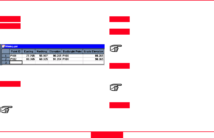
Creating fixpoint files
> Step 1 Open a new file: File
!!
!!
!
New
> Step 2 Enter point number, coordinates,
backsight reference point, grade
elevation.
> Step 3 Save the created coordinate list:
File
!!
!!
!
Save As
In the fixpoint entry module, the
"Mining Editor" allows users to create,
view, modify and save coordinate lists.
Define tolerances
> Step 1 Open tolerances:
Options
!!
!!
!
Tolerances
!!
!!
!
Edit
> Step 2 Enter a password.
Create a new password:
Options
!!
!!
!
Password
> Step 3 Select a measuring sequence
(BFFB, BFBF or BBFF).
(B = Backsight point and F= Foresight
point).
> Step 4 Enter number of sets.
TPS400 Mining Manual-1.0.0en Mining Editor
34
First Example (Creating fixpoint files, define tolerances, uploading), continued
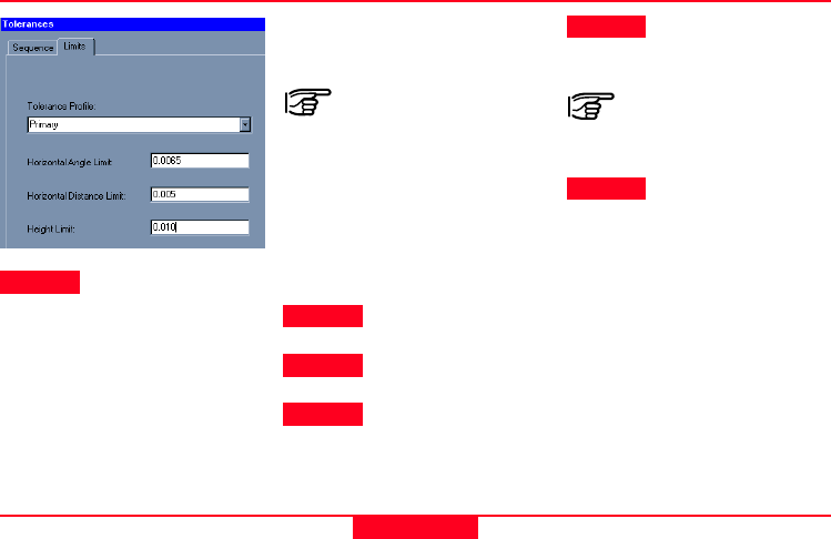
> Step 5
a) Select a tolerance type
(Primary, Secondary,
Tertiary).
b) Enter the values for:
• Horizontal Angle Limit
• Horizontal Distance Limit
• Height Limit
Upload Fixpoints and
Tolerances to the instrument
Ensure that the unit
setting on the
instrument (Menu /
All Settings / Unit
Settings) is identical
to the units set in
the "Mining Editor"
(Options
!!
!!
!
Settings).
> Step 1 Open a fixpoint file:
File
!!
!!
!
Open
> Step 2 Choose Upload:
Data
!!
!!
!
Upload
> Step 3 Select a job.
> Step 4 Enter jobname,
operator and
comments.
Operator and
comments are
optional.
> Step 5 Select a tolerance
type.
TPS400 Mining Manual-1.0.0en Mining Editor
35
Second Example (Importing of fixpoints in ASCII format)
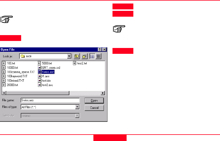
Process import fixpoint files
The "Mining Editor" allows to import
fixpoint files in ASCII format.
> Step 1 File
!!
!!
!
Open
> Step 2 ASCII-File search and select.
> Step 3 Open the selected file.
Follow the wizard onscreen
instructions to produce the correct
format.
> Step 4 Save the created file:
File
!!
!!
!
Save as

Leica Geosystems AG
CH-9435 Heerbrugg
(Switzerland)
Phone +41 71 727 31 31
Fax +41 71 727 46 73
www.leica-geosystems.com
Printed in Switzerland - Copyright
Leica Geosystems AG, Heerbrugg,
Switzerland 2003
Original text
734337-1.0.0en
Leica Geosystems AG, Heerbrugg,
Switzerland, has been certified as
being equipped with a quality
system which meets the Internatio-
nal Standards of Quality Manage-
ment and Quality Systems (ISO
standard 9001) and Environmental
Management Systems
(ISO standard 14001).
Total Quality Management-
Our commitment to total customer
satisfaction
Ask your local Leica Geosystems
agent for more information about
our TQM program
