Leidos Innovations NORMARC7033 7033 Dual Frequency Glide Path User Manual General Description 7011
Lockheed Martin Air Traffic Management 7033 Dual Frequency Glide Path General Description 7011
Contents
- 1. Normarc 7033 Instrument Landing System Operating Manual
- 2. Normarc 7033 ILS Technical Handbook
- 3. Normarc ILS Installation and Commissioning Hanbook Vol 1
- 4. Normarc ILS Installation and Commissioning Hanbook Vol 2
- 5. Normarc ILS Installation and Commissioning Hanbook Vol 1 and 2
- 6. Normarc ILS General Description
- 7. Normarc 7033 Instrument Landing System Operation Manual
- 8. Normarc ILS Installation and Commissioning Handbook Vol 1
- 9. Normarc ILS Installation and Commissioning Handbook Vol 2
- 10. Normarc ILS Installation and Commissioning Handbook Vol 1 and 2
- 11. Normarc 7033 ILS General Description
Normarc 7033 ILS General Description

©1999 Navia Aviation AS
NORMARC 7033
INSTRUMENT LANDING SYSTEM
GENERAL DESCRIPTION

©1999 Navia Aviation AS

©1999 Navia Aviation AS Table of contents
GENERAL DESCRIPTIONNORMARC 7033
INSTRUMENT LANDING SYSTEM
iii
TABLE OF CONTENTS
DESCRIPTION OF NORMARC 7033 2-FREQUENCY SYSTEM .....................1
1 GENERAL DESCRIPTION ..............................................................................1
1.1 Technical Specifications..................................................................................... 1
1.1.1 Signal Minimum Performance GP ...............................................................1
1.1.2 Environmental Characteristics ..................................................................... 2
1.1.3 EMC Characteristics .................................................................................... 2
1.1.4 Mechanical Characteristics..........................................................................3
1.1.5 Power Supply...............................................................................................3
1.2 General Information............................................................................................ 3
1.2.1 Introduction.................................................................................................3
1.2.2 Product Type Numbers................................................................................7
1.2.3 Abbreviations ............................................................................................... 7
2 PHYSICAL ORGANIZATION...........................................................................8
2.1 Module and Assembly Location .........................................................................8
2.2 Power Supply .....................................................................................................9
3 SYSTEM DESCRIPTION.................................................................................12
3.1 Overview ............................................................................................................ 12
3.2 Physical Description........................................................................................... 12
3.3 Monitors.............................................................................................................. 13
3.4 Transmitters / Modulators...................................................................................13
3.5 TX Control .......................................................................................................... 13
3.6 Remote Monitoring (RMS) Unit .......................................................................... 14
3.7 Remote Control Unit........................................................................................... 14
3.8 Remote Slave Panel........................................................................................... 14
3.9 Remote Maintenance Monitoring (RMM) ...........................................................14
3.9.1 RMM Access................................................................................................16
3.9.2 Local Keyboard/Display Functions ..............................................................16
3.9.3 Diagnostic functions.....................................................................................17
4 ELECTRICAL INSTALLATION ........................................................................18
4.1 Connection Overview .........................................................................................18
4.2 Power and Battery..............................................................................................18
4.3 RF Inputs............................................................................................................20
4.4 RF Outputs......................................................................................................... 20
4.5 DC Loop ............................................................................................................. 21
4.6 Remote Control .................................................................................................. 22
4.7 PC and Modem ..................................................................................................23
4.8 DME ................................................................................................................... 24
4.9 Analog Inputs .....................................................................................................25
4.10 Digital Inputs and Outputs..................................................................................26
4.11 Battery Warning.................................................................................................. 27
4.12 Remote control connections...............................................................................28
4.13 Remote slave connection................................................................................... 30
4.14 Interlock switch connection ................................................................................31


©1999 Navia Aviation AS List of Figures
GENERAL DESCRIPTIONNORMARC 7033
INSTRUMENT LANDING SYSTEM
v
LIST OF FIGURES
Figure1-1 Typical ILS installation ..........................................................................4
Figure1-2 Glidepath block diagram .......................................................................4
Figure1-3 Glidepath Antenna ................................................................................5
Figure1-4 Glidepath Cabinet Installation ..............................................................6
Figure2-1 NM 7033 Module Location - Front view. ...............................................9
Figure2-2 NM 7033 Module Location - Rear view of main section. ......................10
Figure2-3 NM 7033 Module Location - Front view of wall-mounted section .........11
Figure3-1 ILS block diagram. ................................................................................12
Figure3-2 The NM 7000 series RMM/RMS systems. ...........................................15
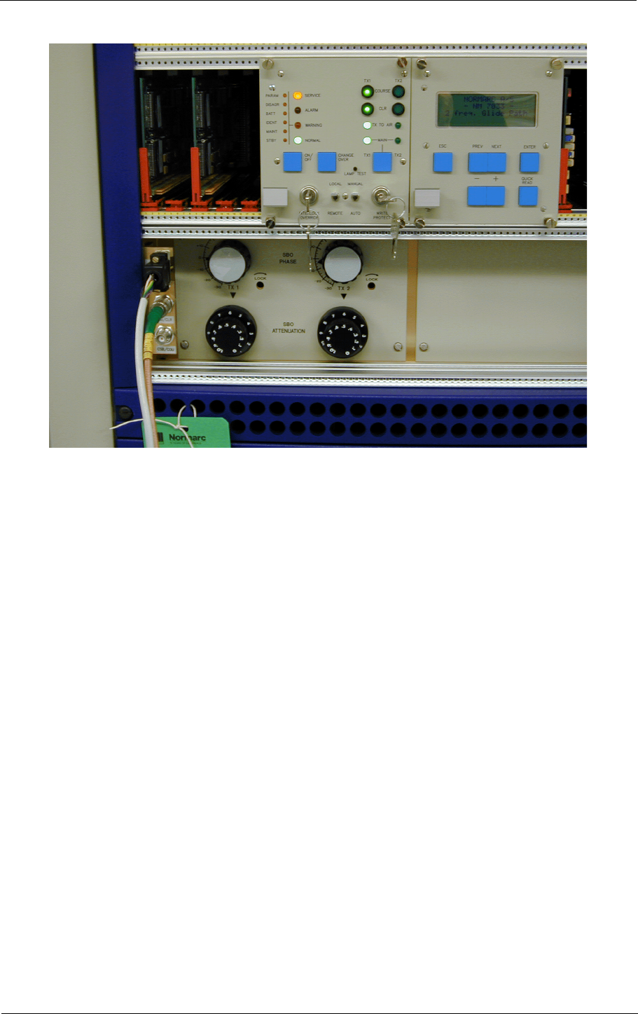
Figure3-3 Local Control Panel ..............................................................................17
Figure4-1 ILS main cabinet connection overview. ................................................18
Figure4-2 Power and backup battery connections. ..............................................19
Figure4-3 RF input connections. ...........................................................................20
Figure4-4 RF output connections. ........................................................................20
Figure4-5 DC loop connections. ...........................................................................21
Figure4-6 Remote control connection. ..................................................................22
Figure4-7 PC and modem connections. ...............................................................23
Figure4-8 DME connections. ................................................................................24
Figure4-9 Analog input connections. ....................................................................25
Figure4-10 Digital input/output connections. ..........................................................26
Figure4-11 Battery warning connections. ...............................................................27
Figure4-12 Remote control to ILS connection ........................................................28
Figure4-13 Remote control power supply connections ...........................................29
Figure4-14 Remote slave connection .....................................................................30
Figure4-15 Interlock switch connection ..................................................................31


GENERAL DESCRIPTION
NORMARC 7033
1-1
©1999 Navia Aviation AS
INSTRUMENT LANDING SYSTEM
GENERAL DESCRIPTION
DESCRIPTION OF NORMARC 7033 2-FREQUENCY SYSTEM
1 General Description
1.1 Technical Specifications
NM 7033 Dual-Frequency Glidepath Cabinet.
1.1.1 Signal Minimum Performance GP
Transmitter
Frequency range 328.6-335.4 MHz
Frequency tolerance + 0.002%
Output power (CSB + SBO) Course 3-7 W adjustable
Output power (CSB) Clearance 0.3-1 W adjustable
Harmonic radiation 2.5 uW maximum
RF difference frequency (2-freq. only) 15 kHz + 5 kHz
Spurious 25 uW maximum
Output power stability + 0.2 dB
CSB/SBO stability + 0.3 dB
Modulator - Course line
Modulation depth 90/150 Hz 40%
adjustable range 10-44%
SDM stability + 0.8% SDM
DDM stability + 0.2% DDM
Frequency tolerance + 0.05 Hz
Total harmonic dist. (90/150 Hz) 1% maximum
Phase locking (90 Hz to 150 Hz) 5° maximum ref 150 Hz
SBO phaser adjustment range + 30°
Modulator - Clearance
Modulation depth 80%
90 Hz component 20%
150 Hz component 60%
Adjustable range DDM 20-100% 150 Hz dominance
Adjustable range SDM 20-90%
Stability + 0.2 dB
Frequency tolerance + 0.05 Hz
Total harmonic dist. (90/150 Hz) 1% maximum
Phase locking (90 Hz to 150 Hz) 5° maximum ref 150 Hz
Monitoring
Alarm Functions Range (*)
RF power reduction 1-5 dB
Change of nominal CL + 10-60 uA

NORMARC 7033
INSTRUMENT LANDING SYSTEM
GENERAL DESCRIPTION
GENERAL DESCRIPTION ©1999 Navia Aviation AS
1-2
* asymmetrical limits are possible.
1.1.2 Environmental Characteristics
1.1.3 EMC Characteristics
Change of nominal DS from nominal
value + 10-60 uA
Change of nominal CLR (2-freq only) + 10-60 uA
Change of nominal NF + 10-60 uA
Change of nominal SDM + 2-8% SDM
Difference frequency (2-freq. only) + 2-5 kHz
Total period of radiation out of tolerance 1-6 sec.
Additional NF time delay 0-20 sec.
Line break, ILS - Remote Control (disa-
ble optional)
Monitor input levels:
Adjustment range, nominal level -5 to –34 dBm
AGC range for less than 1%
change in SDM 5 dB
Monitor stability at nominal levels:
RF power values + 0,3 dB
DDM values + 1 uA
SDM values + 1% SDM
Warning Functions:
RF power reduction 40-75% of Alarm limit
Change of nominal CL 40-75% of Alarm limit
Change of nominal DS 40-75% of Alarm limit
Change of nominal CLR 40-75% of Alarm limit
Change of nominal NF 40-75% of Alarm limit
Change of SDM 40-75% of Alarm limit
Difference frequency 40-75% of Alarm limit
Mains failure
Remote Control
Data Transmission Medium 2-wire line, 600 ohm
Data modulation serial, FSK
Transmitter level -10dBm + 2 dB
Receiver dynamic range -10dBm to -34dBm
Operating temperature -10 to +55 °C
Storage temperature -30 to +60 °C
EMR: EN 55022 class B
Spurious and harmonics: CISPR 22

GENERAL DESCRIPTION
NORMARC 7033
1-3
©1999 Navia Aviation AS
INSTRUMENT LANDING SYSTEM
GENERAL DESCRIPTION
1.1.4 Mechanical Characteristics
The ILS rack is wall mounted. The remote control and slave panels fit a standard 3U (132mm)
high 19" subrack.
1.1.5 Power Supply
1.2 General Information
This paragraph gives a description of a typical ILS installation and the Normarc Glidepath sys-
tem. Conventions and abbreviations used in this manual are also given.
1.2.1 Introduction
This is an overview of Normarc's NM703X ILS glidepath systems.
1.2.1.1 ILS Overview
A complete Instrument Landing System comprises:
• A LOCALIZER SYSTEM, producing a radio course to furnish lateral guidance to the airport
runway.
• A GLIDE PATH SYSTEM, producing a radio course to furnish vertical guidance down the
correct descent angle to the runway.
• MARKER BEACONS, to provide accurate radio fixes along the approach course.
Dimensions: (H x W x D)
ILS Rack: 1020x600x500 mm
Remote control: 129x71x170 mm
Slave panels: 129x41x170 mm
Weight: 85 kg – 95 kg depending on model
External supply:
Input voltage: 230V +15%/-20%,45-65 Hz or120V +15%/-20%,
45-65 Hz
Output voltage: 27,6V
Output current: 20A max
ILS cabinet
Input voltage 22-28V DC
Current consumption: 8A – 14A depending on configuration
Stand-by Battery 24V DC nominal, 85 Ah-110Ah valve regulated
lead-acid battery recommended
NORMARC 7033
INSTRUMENT LANDING SYSTEM
GENERAL DESCRIPTION
GENERAL DESCRIPTION ©1999 Navia Aviation AS
1-4
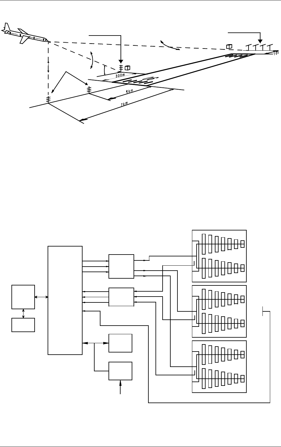
The layout of a typical ILS airport installation is shown below.
Figure1-1 Typical ILS installation
1.2.1.2 Glidepath Overview
The complete ILS Glidepath system comprises:
• A GP transmitter/monitor cabinet
• An antenna distribution network
• A monitor network
• A GP antenna array
• Near-field monitor antenna
A block diagram is shown below:
Figure1-2 Glidepath block diagram
Localizer
110 MHz
Glide Path
330 MHz
Marker Beacon
75MHz
3°
HBK547-1
GP-BLOCK DIAGRAM
HBK205-1
TRANSMITTER
AND
MODULATOR
I and II
MONITOR
I and II
REMOTE
CONTROL
UNIT
SLAVE
PANEL
CSB CL
SBO CL
CSB CLR*
CL
CLR*
DS
NF
ANTENNA
DISTRIBU-
TION NETW.
**
MONITOR
NETWORK
24V
BATTERY
SUPPLY
POWER
MAINS INPUT
220V/110V AC
U
L
M
ILS Localizer
and Glide Path
GP
TRANSMITTER
***
* CLR signals only used for 2-frequency systems.
** Antenna distribution network not used for Null Reference.
*** Middle antenna used for M-Array and Modified M-Array.

NORMARC 7033
INSTRUMENT LANDING SYSTEM
GENERAL DESCRIPTION
GENERAL DESCRIPTION ©1999 Navia Aviation AS
1-6
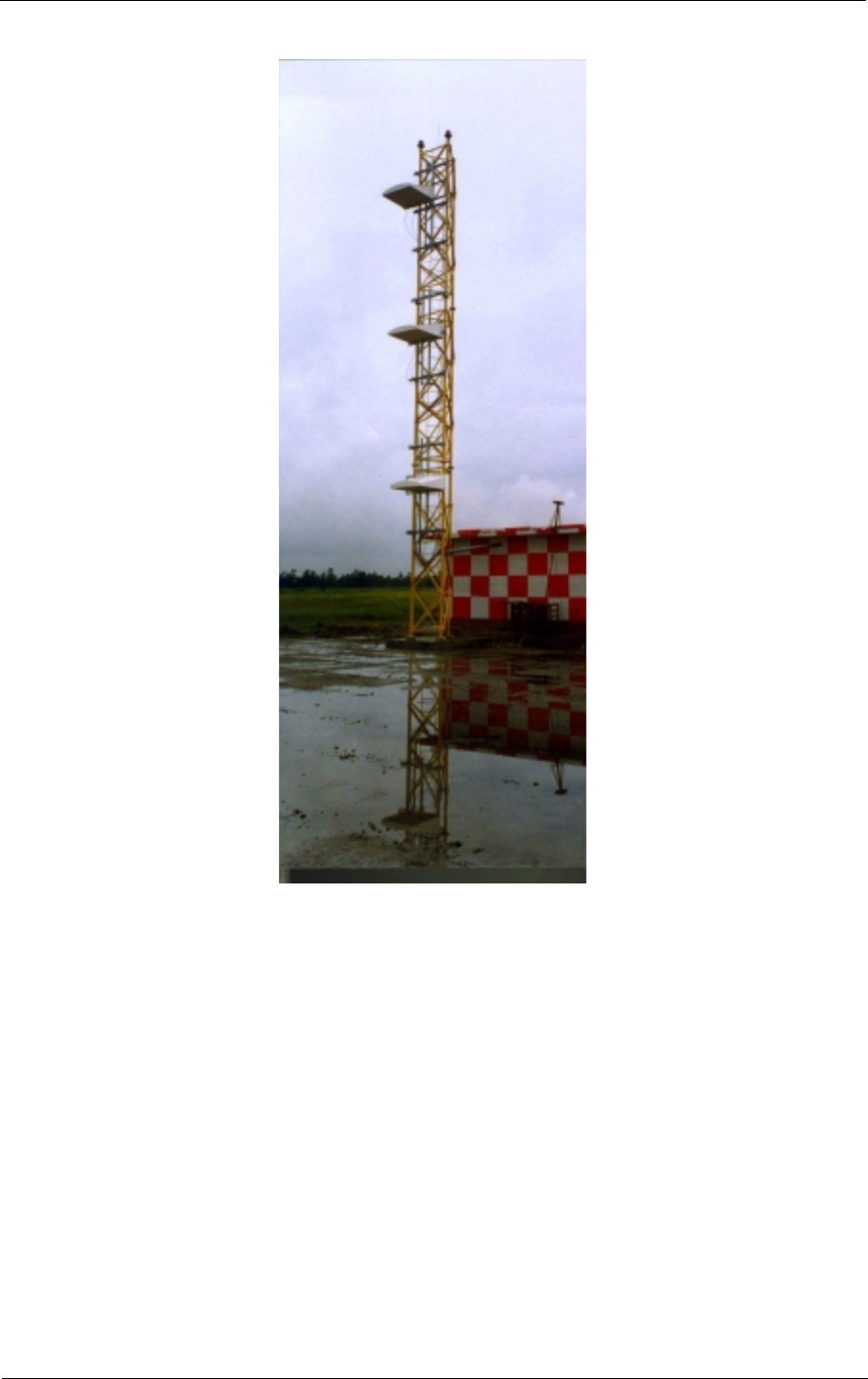
Figure1-4 Glidepath Cabinet Installation
1.2.1.3 Glidepath Description
To shape the glide path signal, ground plane reflection from an area in front of the antenna
array is necessary. The specific requirements to the area are given in the antenna handbook.
The glide path site may be located on either side of the runway, but the most reliable operation
will be obtained if the site is selected on terrain least obstructed by taxiways, aircraft holding
aprons, parking ramps, buildings, power lines etc. The site should offer the widest area of
smooth ground with possibilities of levelling without excessive physical or economical effort, if
indeed levelling is deemed necessary.
The glide path antenna system should be located at a distance of 75-200 m from the runway
center line. The distance from the runway threshold is a function of several factors upon which
establishment of the optimum operational conditions depend. These factors are:
GENERAL DESCRIPTION
NORMARC 7033
1-7
©1999 Navia Aviation AS
INSTRUMENT LANDING SYSTEM
GENERAL DESCRIPTION
1. The glide path angle.
2 Threshold crossing height requirements.
3. Obstruction clearance requirements
4 The slope of the terrain in front of the antenna system.
5. The extent of smooth terrain in the site area and beyond the threshold.
1.2.2 Product Type Numbers
The Normarc product numbering system is based on the following three levels:
•System
• Assembly
• Module
Systems have type numbers starting with NM, for example NM 7033. Systems consist of
assemblies, modules and parts.
Assemblies have type numbers consisting of three letters, a three- or four- digit number and a
letter, for example LPA 1230A. LPA is an abbreviation of Localizer Power amplifier Assembly,
1230 is a running number, and the last letter is the variant designator. Assemblies can consist
of assemblies, modules and parts.
Modules have type numbers consisting of two letters, a three- or four- digit number and a let-
ter, for example FD 1235A. FD is an abbreviation of Feedback Detector, 1235 is a running
number, and the last letter is the variant designator. Modules consist of parts.
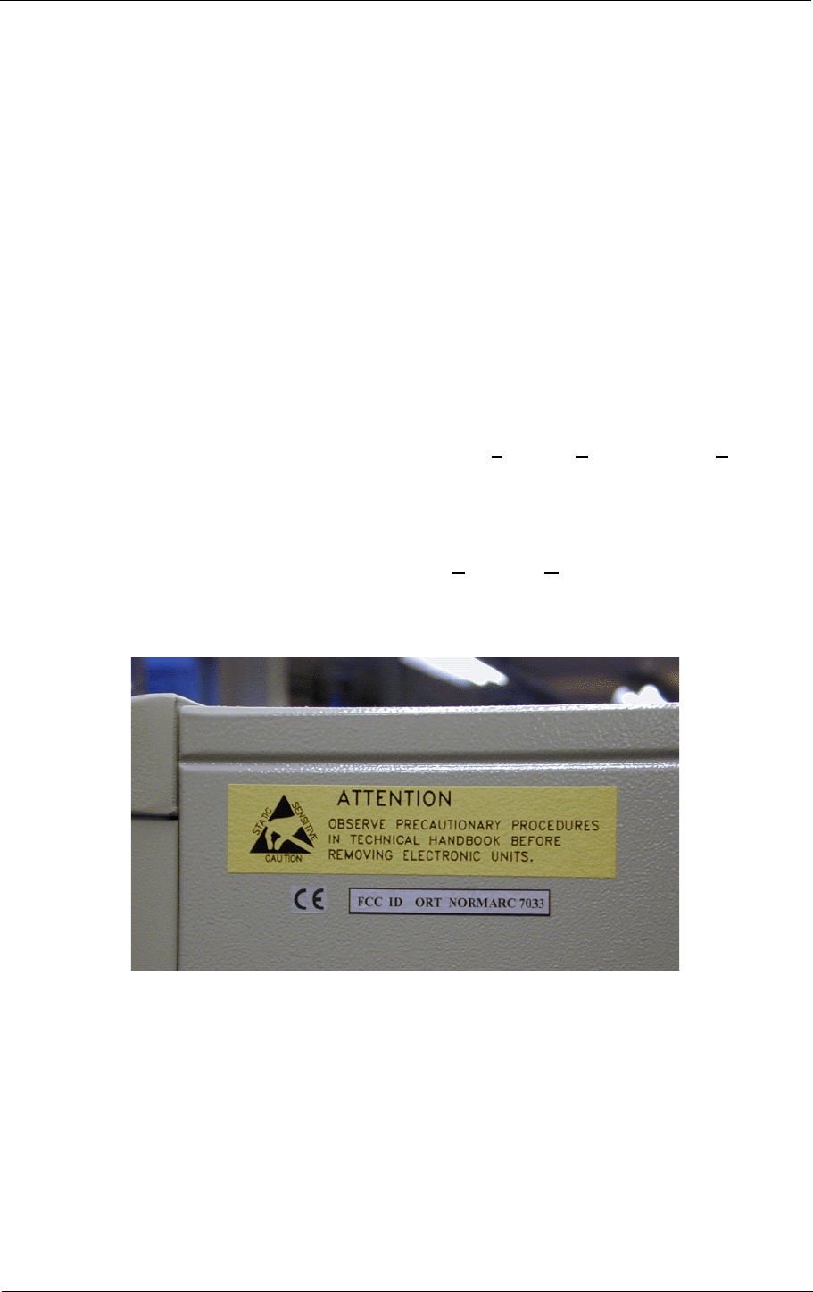
Glidepath Cabinet External Label
1.2.3 Abbreviations
AC Alternating Current
ADC Analog to Digital Converter
AGC Automatic Gain Control
CL Course Line
CLR Clearance
COU Course
CPU Central Processing Unit
CS Course Sector

NORMARC 7033
INSTRUMENT LANDING SYSTEM
GENERAL DESCRIPTION
PHYSICAL ORGANIZATION ©1999 Navia Aviation AS
2-8
DAC Digital to Analog Converter
DC Direct Current
DDM Difference in Depth of Modulation
DF Difference Frequency
DL Dc Loop
DS Displacement Sensitivity
DSP Digital Signal Processor
EEPROM Electrically Erasable Progammable Read Only Memory
EMC ElectroMagnetic Compatibility
EMI ElectroMagnetic Interference
EPROM Erasable Programmable Read Only Memory
FFT Fast Fourier Transform
FIFO First-In-First-Out
FPGA Field Programmable Gate Array
GPA Glidepath Power amplifier Assembly
I/F InterFace
I²C Inter Integrated Circuit
IIC Same as I²C
ILS Instrument Landing System
LED Light Emitting Diode
LF Low Frequency
LLZ Localizer
LPA Localizer Power amplifier Assembly
LRU Line Replacable Unit
MCU Monitor Combiner Unit
NAV NAVigation signals
NF Near Field
PC Personal Computer
RAM Random Access Memory
RF Radio Frequency
RMM Remote Maintenance Monitor
RMS Remote Monitoring System
ROM Read Only Memory
RTC Real Time Clock
SC Station Control
SDM Sum in Depth of Modulation
SPA Same Parameter Alarm
SRAM Static Random Access Memory
STB Standby
SW SoftWare
TRM TeRMinator
TX Transmitter
2 Physical Organization
2.1 Module and Assembly Location
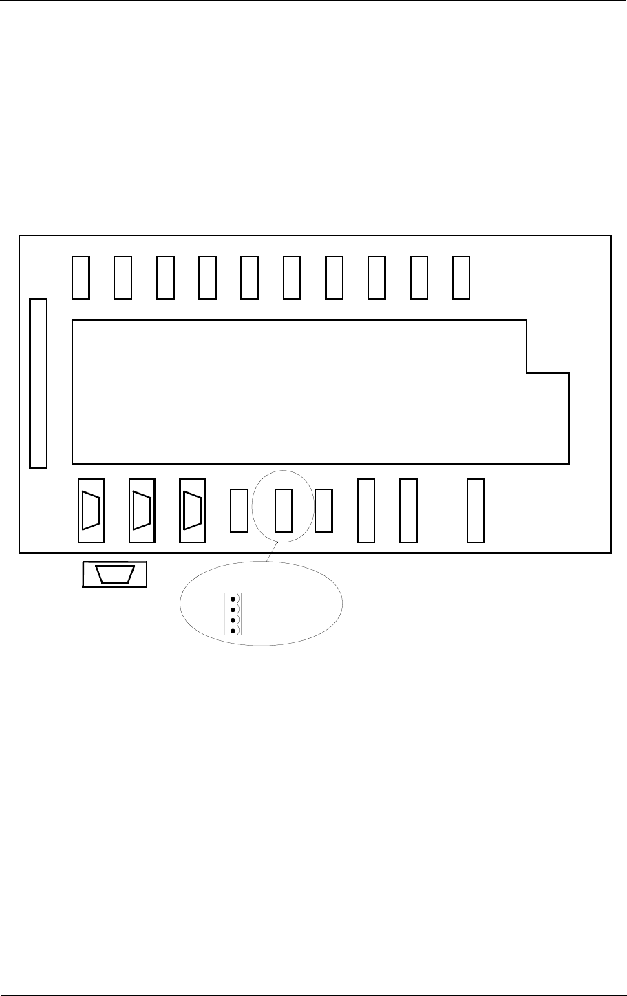
The figures on the following pages show the locations of the modules in the main cabinet.
Figure 2-1 shows the main section of the GP cabinet from a front view, with indications of the
plug-in board locations.

PHYSICAL ORGANIZATION
NORMARC 7033
2-9
©1999 Navia Aviation AS
INSTRUMENT LANDING SYSTEM
GENERAL DESCRIPTION
Figure 2-2 shows the same section from a rear view, while Figure 2-3 shows the top half of the
wall-mounted section.
In addition, the Remote Control Assembly RCA1240C/D and Remote Slave SF 1344A are
installed in the technical control room and the control tower, respectively.
2.2 Power Supply
An External Power Supply, operating at 230V/120V mains input and providing 27V at 20A, is
normally supplied with the equipment. In special cases, a second external power supply is
supplied.
Figure2-1 NM 7033 Module Location - Front view.
11
PS 1227A
TCA 1218A
HBK 536-1
MF 1219A
OS1221B
LF1223A
RMA1215A
GPA1232A
GPA1231A
COA1207C
MO1212A

NORMARC 7033
INSTRUMENT LANDING SYSTEM
GENERAL DESCRIPTION
PHYSICAL ORGANIZATION ©1999 Navia Aviation AS
2-10
Figure2-2 NM 7033 Module Location - Rear view of main section.
SBO 1
IN IN OUT
SBO 2 SBO
DUMMY OUT
SBO CSB
DUMMY IN
CSB SBO 1
IN OUT
SBO 2 SBO
DUMMY OUT
SBO CSB
DUMMY
CSB
MB 1203
COA 1207C
TX1
CL
TX2
CL
TX1
CLR
TX2
CLR
AA
VIEW A-A
HBK 593-1

NORMARC 7033
INSTRUMENT LANDING SYSTEM
GENERAL DESCRIPTION
SYSTEM DESCRIPTION ©1999 Navia Aviation AS
3-12
3 System description
This chapter gives a functional overview of the NM70xx ILS systems.
3.1 Overview
The complete ILS electronic system is housed in a compact, wall mounted cabinet. The cabi-
net and the electronics, except for RF units, are common to the LLZ and GP systems
.
Figure3-1 ILS block diagram.
The ILS cabinets can be configured for Cat I, Cat II, or Cat III requirements with no basic
changes.
Eight models are available:
NM 7011 Single frequency LLZ
NM 7012 Single frequency LLZ with hot standby monitoring (Cat III)
NM 7013 Two frequency LLZ
NM 7014 Two frequency LLZ with hot standby monitoring (Cat III)
NM 7031 Single frequency GP
NM 7032 Single frequency GP with hot standby monitoring (Cat III)
NM 7033 Two frequency GP
NM 7034 Two frequency GP with hot standby monitoring (Cat III)
The system is based on modern technology with extensive Remote Monitoring and Mainte-
nance capabilities, and very high reliability and integrity. To meet this objective, the monitor
comparator and station control are based on digital hardware, while the RMS interface is
microprocessor based.
3.2 Physical Description
The cabinet contains three sections:
• The electronics card cage
• The change-over section
• The transmitter / PA section
The electronics card cage contains the RF oscillators, the LF signal generators, the monitors,
Monitor
RMS
Monitor
TX control Changeover
Section
Monitor
input
signals
Monitor
input
signals Transmitter
Transmitter
NAV
signals
out
Remote
Control
External
sensors
Comm.
ports
Data and
diagnostics
HBK573-1

SYSTEM DESCRIPTION
NORMARC 7033
3-13
©1999 Navia Aviation AS
INSTRUMENT LANDING SYSTEM
GENERAL DESCRIPTION
the station control, the RMS processor, and the voltage regulators.
The change-over section contains coaxial relays, attenuators and phasers for the RF outputs.
The transmitter / PA section contains the PA blocks including couplers etc. for each output.
The cabinet is divided in two parts, with the rear part fixed to a wall, and the front part hinged
to give access to interior of the cabinet.
All external connections are made to the rear part of the cabinet.
3.3 Monitors
The ILS has duplicated monitors with inputs for Course Line (CL), Displacement Sensitivity
(DS), Near Field (NF), and Clearance (CLR) (Dual Freq. only). The signals are detected by
the input stage, and then digitized. In the next block they are filtered by a Fast Fourier Trans-
form performed by a signal processor. The results for each parameter is then compared with
stored limits in a digital hardware comparator.
Each of the two monitors consists of two modules. For Cat III use, Hot Standby monitoring can
be added by using one additional monitor and associated RF couplers and combiners.
The design of the monitors ensures a very high integrity due to the use of digital hardware for
the alarm comparators and a very simple Fast Fourier filtering with a signal processor. In addi-
tion, the monitor is checked by automatic self-tests.
The alarm limits are stored locally in EEPROM, and can be updated from the RMS processor,
with a separate hardware write protection to ensure that the integrity is not affected by the
RMS system.
3.4 Transmitters / Modulators
The transmitters are duplicated, either single frequency or dual frequency. Each transmitter
consists of a RF oscillator, a LF generator, and one or two PA blocks (single or dual fre-
quency).
The RF oscillator uses a synthesizer for easy frequency changes and simple logistics. The
oscillator has two outputs for use in dual frequency systems.
The LF generator contains the generators for 90Hz, 150Hz and 1020Hz signals, the ident
keyer / sequencer and interface for DME master or slave keying. All signals are generated by
division from a common clock oscillator, ensuring very stable phase relations between the
modulation signals.
The modulation balance, modulation sum, RF level and Ident morse code are set in this mod-
ule by means of multiplying digital to analog converters. The values are stored locally in
EPROM and can be updated from the RMS processor with hardware write protection.
The same LF generator is used for single and dual frequency systems.
3.5 TX Control
The TX control unit controls the system dependent on alarms from the monitors and inputs

NORMARC 7033
INSTRUMENT LANDING SYSTEM
GENERAL DESCRIPTION
SYSTEM DESCRIPTION ©1999 Navia Aviation AS
3-14
from the local control, the remote control and, optionally, the RMS system. It also generate
status information to the same units. The local control and status indicators are a part of the
TX Control unit.
All functions in the TX Control are based on digital hardware to ensure the highest integrity.
3.6 Remote Monitoring (RMS) Unit
The RMS unit contains the system microprocessor. It handles storage and read-out of monitor
parameters, measurements for maintenance and fault finding, and performs fault analysis to
isolate faults to line replaceable modules. It is also used to set monitor limits and transmitter
adjustments.
The RMM handles communication to local and remote RMS computers, and in addition it han-
dles a small display and keyboard for parameter setting and readout.
3.7 Remote Control Unit
The remote control unit is used in the tower or in the technical control room. It has indicators
for operating status as well as detailed warnings and an aural alarm device with reset. It can
control equipment on/off and change-over, and has an Access Grant-switch to allow remote
control from the RMS system.
The Remote Control Unit is connected to the ILS by one telephone pair cable.
3.8 Remote Slave Panel
The slave panel is connected to the remote control by a multipair wire. It is intended for use in
the control tower. It has indicators for normal / warning / alarm and has an aural alarm device.
in addition it can turn the equipment on and off, and has an aural alarm reset.
Optionally a slave panel with remote control functionality can be delivered.
3.9 Remote Maintenance Monitoring (RMM)
The NM7000 series has a built-in Remote Maintenance Monitoring system. This system con-
sists of the RMS system, remote PC terminals with the RMM program installed, and the local
keyboard/display. Figure 3-2 illustrates the RMM/RMS systems

SYSTEM DESCRIPTION
NORMARC 7033
3-15
©1999 Navia Aviation AS
INSTRUMENT LANDING SYSTEM
GENERAL DESCRIPTION
.
Figure3-2 The NM 7000 series RMM/RMS systems.
The centre of the RMS system is a CPU with the RMS core program. The RMS collects mea-
surements and diagnostic data, and makes them available to the user. The collected informa-
tion allows easy and cost effective maintenance, fault finding and routine reporting. In
addition, system settings are distributed and parameter readings are collected via the RMS/
CPU.
External personal computers are used for a user-friendly interface to the RMM system. The
equipment has three serial output ports, typically used to connect a local PC, a PC in the air-
port technical equipment room, and a modem for connection to a central maintenance facility.
RMS
hardware
RMS
core
program
Local
measuring
points
Maintenance
data bus
RMS
data bus
Local
parameter
storages
Local
Keyboard/
Display
Modem
NM70xx
RMS system
RMM system
Local Remote 1 Remote 2
RMM
program RMM
program RMM
program
Modem Modem
Modem
HBK 598-1

NORMARC 7033
INSTRUMENT LANDING SYSTEM
GENERAL DESCRIPTION
SYSTEM DESCRIPTION ©1999 Navia Aviation AS
3-16
The local keyboard/display allow readings and control through an LCD display and a seven-
button keypad. This gives access to the RMM functionality without the need for a PC.
3.9.1 RMM Access
Access to the RMM system is controlled by multiple hardware and software access controls.
One password is required for each access level, i.e. one password for level 1, two for level 2
and three for level 3. Optional hardware controls may inhibit writing in the upper access levels.
Access level 1
• Readout of all the monitor values, warning and alarm limits.
• Readout of all the maintenance values and warning limits.
• Readout of all the delays.
• Readout of all the monitor DDM offsets.
Access level 2
• TX1 and TX2: 90/150 Hz on/off.
• TX1 and TX2: morse normal, continuous, TST or off.
• TX1 and TX2: test-signal 90 Hz or 150 Hz dominance on/off.
• Diagnostics.
Access level 3
• Settings of all the monitor warning and alarm limits.
• Settings of all the maintenance warning limits.
• Settings of all the delays.
• Settings of all the monitor DDM offsets.
3.9.2 Local Keyboard/Display Functions
Through a menu-based interface all main commands, adjustments and monitor limits are
accessible from the front panel keypad and LCD display. In addition a quick-read function
gives read-out of all main monitor parameters in a glance.
SYSTEM DESCRIPTION
NORMARC 7033
3-17
©1999 Navia Aviation AS
INSTRUMENT LANDING SYSTEM
GENERAL DESCRIPTION
Figure3-3 Local Control Panel
3.9.3 Diagnostic functions
The system contains internal measuring points and diagnostic functions to isolate faults to
failed modules. The values measured are referred to as maintenance parameters. Please
refer to the NM70xx Operating Manual.

NORMARC 7033
INSTRUMENT LANDING SYSTEM
GENERAL DESCRIPTION
ELECTRICAL INSTALLATION ©1999 Navia Aviation AS
4-18
4 Electrical Installation
This paragraph describes the external electrical connections of the NM 7033 main cabinet.
4.1 Connection Overview
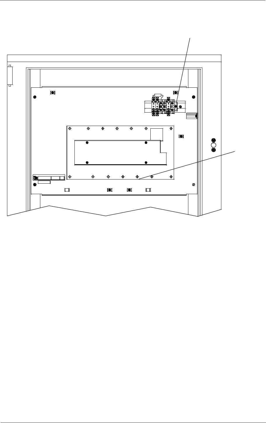
The ILS main cabinet consists of three connector sites, illustrated in Figure 4-1
• The ILS RF signals to and from the antenna system are connected at the top of the main
cabinet. These connectors may be moved to the bottom, see Mechanical Installation.
• The power supply (supplies) and the backup battery are connected to the power connector
rail inside the cabinet back section.
• All other external connections are sited on the Connection Interface board CI1210A inside
the cabinet back section.
Figure4-1 ILS main cabinet connection overview.
4.2 Power and Battery
The power supply and the backup battery are connected to the power connector rail inside the
cabinet back section as shown in Figure 4-2. If two power supplies are used, these are parallel
RF CONNECTIONS
CABLE FEEDTHROUGH
COU/SBO
CLR/SBO
CLR/CSB
OUT
COU/CSB
CLR
DS
NF
IN CL
1 AC LEVEL MEASUREMENT
CI 1210A CONNECTIONS
8 DIGITAL INPUT/OUTPUT
3 DIFFERENTIAL ANALOG
2 TEMP SENSORS
1 DME
1 REMOTE CONTROL
3 RS 232
4 DC LOOPS
BATTERY +27V
0V
POWER RAIL CONNECTIONS
SUPPLY
POWER +27V
0V
HBK574-2
ELECTRICAL INSTALLATION
NORMARC 7033
4-19
©1999 Navia Aviation AS
INSTRUMENT LANDING SYSTEM
GENERAL DESCRIPTION
coupled outside the cabinet. The cables used should have 4mm2 intersection.
Figure4-2 Power and backup battery connections.
A DC powered modem or other external equipment designed for 22V - 27V DC can be con-
nected to the fused terminal block marked Modem. Maximum current consumption should be
1 A.
Battery
0V +27V
Power Supply
0V +27V
HBK576-3
Fuse 27AT
+27V
Modem

NORMARC 7033
INSTRUMENT LANDING SYSTEM
GENERAL DESCRIPTION
ELECTRICAL INSTALLATION ©1999 Navia Aviation AS
4-20
4.3 RF Inputs
The RF inputs are:
• Course Line - CL.
• Near Field Antenna - NF.
• Displacement Sensitivity - DS.
• Clearance - CLR (two frequency applications only).
These are connected as shown in Figure 4-3 (front view).
Figure4-3 RF input connections.
4.4 RF Outputs
The RF outputs are sited at the cabinet top as illustrated in Figure 4-4. The connections are:
All applications:
• COU SBO - COUrse Tx SideBand Only.
• COU CSB - COUrse Tx Carrier and SideBand.
Two frequency applications:
• CLR SBO - CLeaRance Tx SideBand Only.
• CLR CSB - CLeaRance Tx Carrier and SideBand
Figure4-4 RF output connections.
NF CL CLR DS
HBK577-2
CSBSBO
CLR
CSB
CLR
SBO
HBK578-3

ELECTRICAL INSTALLATION
NORMARC 7033
4-21
©1999 Navia Aviation AS
INSTRUMENT LANDING SYSTEM
GENERAL DESCRIPTION
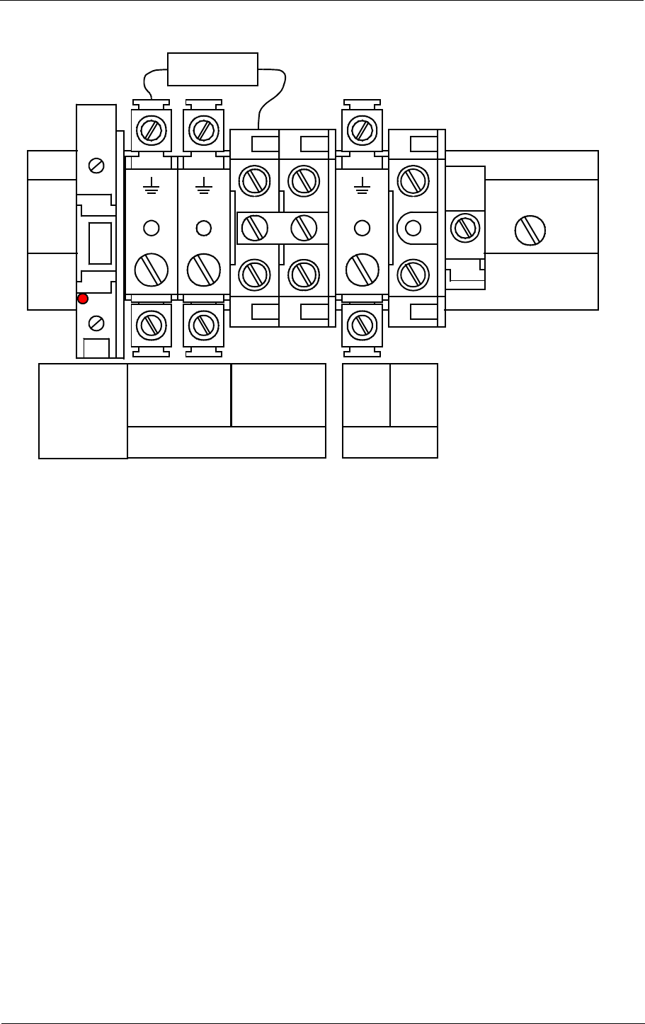
4.5 DC Loop
The DC loops are connected to the Connection Interface board CI1210A in the cabinet back
section. Location and pin out are illustrated in Figure 4-5
•DL_REF* are the reference voltages from the main cabinet.
•DL_DETECT* are the return voltages from the antennas.
•GND is main cabinet ground.
Suitable female connectors are Weidemüller BLZ-5.08/6 or equivalent.
Figure4-5 DC loop connections.
TEMP
INDOOR TEMP
OUTDOOR AC
LEVEL ANALOG
CH.1 ANALOG
CH.2 ANALOG
CH.3 DIGITAL
PORT A DIGITAL
PORT B DIGITAL
PORT C DIGITAL
PORT D
TO MB1203
RS232 RS232 RS232 REMOTE
CONTROL
DC-LOOP DC-LOOP DME
LOCAL REMOTE 2 REMOTE 1 CH.1&2 CH.3&4
1
6
DC-LOOP
CH.1&2
DC-LOOP
CH.3&4
1 - Ch 1 In
2 - Ch 1 Out
3 - GND
4 - Ch 2 In
5 - Ch 2 Out
6 - GND
CI 1210A
1 - Ch 3 In
2 - Ch 3 Out
3 - GND
4 - Ch 4 In
5 - Ch 4 Out
6 - GND
1
6
BATTERY
WARNING
HBK579-2
RADIO LINK

NORMARC 7033
INSTRUMENT LANDING SYSTEM
GENERAL DESCRIPTION
ELECTRICAL INSTALLATION ©1999 Navia Aviation AS
4-22
4.6 Remote Control
The remote control is connected to the Connection Interface board CI1210A as illustrated in
Figure 4-6. The connection of the remote control, remote slave panel and interlock switch is
done at the remote control site and covered in chapter 4.12 - 4.14
•FSK_[P,N] is the modem line pair.
•GND is main cabinet ground.
For normal FSK modem operation the straps S9-11 on CI1210A should be mounted.
A suitable female connector is Weidemüller BLZ-5.08/4 or equivalent.
Figure4-6 Remote control connection.
TEMP
INDOOR TEMP
OUTDOOR AC
LEVEL ANALOG
CH.1 ANALOG
CH.2 ANALOG
CH.3 DIGITAL
PORT A DIGITAL
PORT B DIGITAL
PORT C DIGITAL
PORT D
TO MB1203
RS232 RS232 RS232 REMOTE
CONTROL
DC-LOOP DC-LOOP DME
LOCAL REMOTE 2 REMOTE 1 CH.1&2 CH.3&4
REMOTE
CONTROL
1 - GND
2 - FSK_P
3 - FSK_N
4 - GND
CI1210A
1
4
S9-14
BATTERY
WARNING
HBK580-1
RADIO LINK
ELECTRICAL INSTALLATION
NORMARC 7033
4-23
©1999 Navia Aviation AS
INSTRUMENT LANDING SYSTEM
GENERAL DESCRIPTION
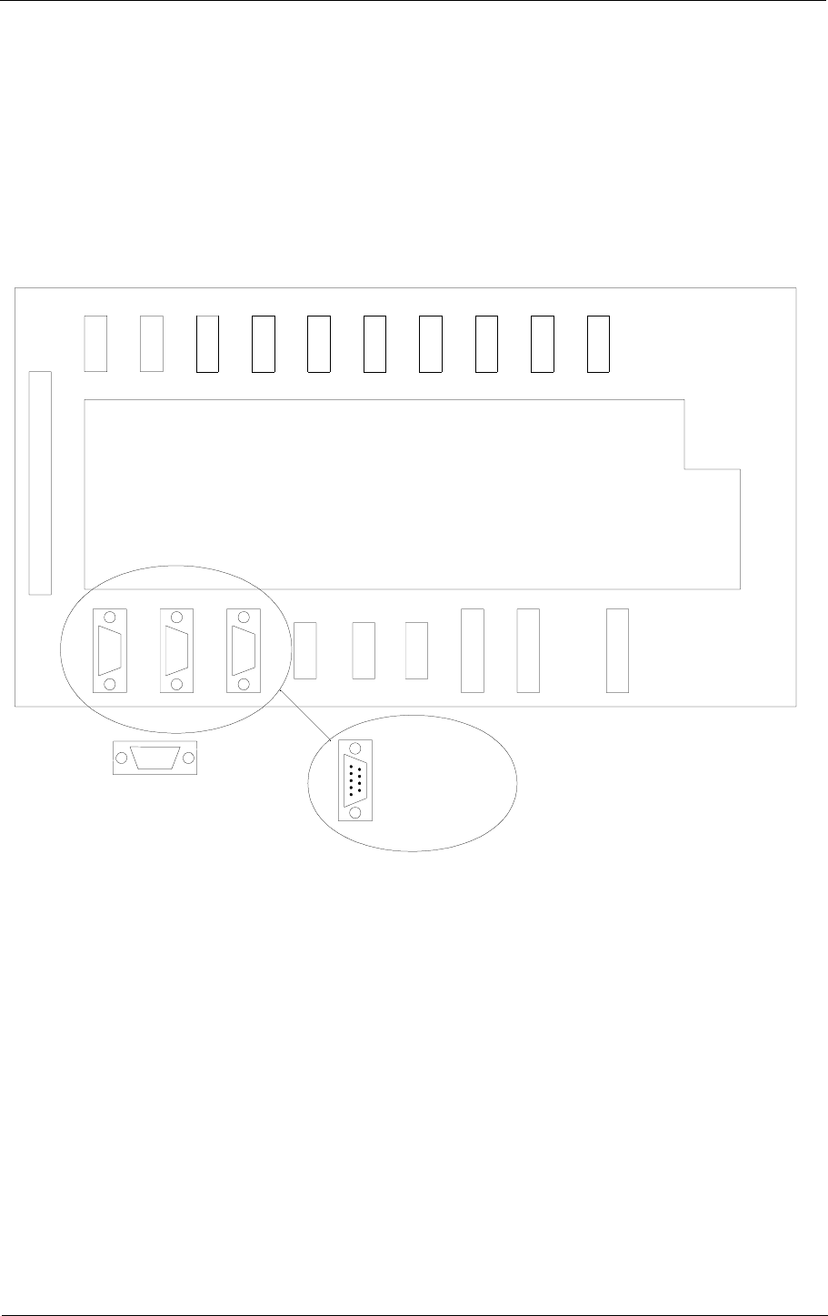
4.7 PC and Modem
PC terminals and modems are connected to the standard pin out RS232, 9 pins DSUB con-
nectors on the Connection Interface board CI1210A as illustrated in Figure 4-7
Recommended connections are:
• LOCAL - the PC located at the ILS main cabinet site.
• REMOTE 1 - the PC located at the airport technical maintenance site.
• REMOTE 2 - distant PC terminals connected through a modem.
Figure4-7 PC and modem connections.
TEMP
INDOOR TEMP
OUTDOOR AC
LEVEL ANALOG
CH.1 ANALOG
CH.2 ANALOG
CH.3 DIGITAL
PORT A DIGITAL
PORT B DIGITAL
PORT C DIGITAL
PORT D
TO MB1203
RS232 RS232 RS232 REMOTE
CONTROL
DC-LOOP DC-LOOP DME
LOCAL REMOTE 2 REMOTE 1 CH.1&2 CH.3&4
CI1210A
1
5
6
9
1 - CD (REMOTE 2 only)
2 - RXD
3 - TXD
4 - DTR (REMOTE 2 only)
5 - GND
6 - DSR (REMOTE 2 only)
7 - RTS
8 - CTS
9 - Not connected
BATTERY
WARNING
HBK581-1
RADIO LINK
NORMARC 7033
INSTRUMENT LANDING SYSTEM
GENERAL DESCRIPTION
ELECTRICAL INSTALLATION ©1999 Navia Aviation AS
4-24
4.8 DME
Distance Measurement Equipment DME is connected to the Connection Interface board
CI1210A as illustrated in Figure 4-8
•ACT_DME[P,N] is the positive and negative terminal of the DME active signal from the
DME, respectively.
•IN_DME[P,N] is the positive and negative terminal of the morse code envelope signal from
the DME, respectively.
•OUT_DME[P,N] is the positive and negative terminal of the morse code envelope signal to
the DME, respectively.
A suitable female connector is Weidemüller BLZ-5.08/6 or equivalent.
Figure4-8 DME connections.
TEMP
INDOOR
TEMP
OUTDOOR
AC
LEVEL
ANALOG
CH.1
ANALOG
CH.2
ANALOG
CH.3
DIGITAL
PORT A
DIGITAL
PORT B
DIGITAL
PORT C
DIGITAL
PORT D
TO MB1203
RS232 RS232 RS232 REMOTE
CONTROL
DC-LOOP DC-LOOP DME
LOCAL REMOTE 2 REMOTE 1 CH.1&2 CH.3&4
1 - ACT_DMEP
2 - ACT_DMEN
3 - IN_DMEP
4 - IN_DMEN
CI1210A
1
6
S1-8
DME
5 - OUT_DMEP
6 - OUT_DMEN
BATTERY
WARNING
HBK582-1
RADIO LINK

ELECTRICAL INSTALLATION
NORMARC 7033
4-25
©1999 Navia Aviation AS
INSTRUMENT LANDING SYSTEM
GENERAL DESCRIPTION
4.9 Analog Inputs
The analog inputs are connected to the Connection Interface board CI1210A as illustrated in
Figure 4-9
The inputs are:
• ANALOG CH.1-3 - three differential DC analog inputs, P is the positive and N is the nega-
tive terminal.
Maximum voltage: ±15V
Input impedance: 10kohms.
• TINDOOR, TOUTDOOR - temperature measurement inputs with interface to an LM35 tem-
perature sensor.
Maximum voltage: ±15V.
Input impedance: 10kohms.
• AC LEVEL - AC level measurement input. Intended for use with a battery eliminator (i.e.
220/9VAC) to monitor the mains voltage.
Maximum voltage: 24Vpp.
Input impedance: 10kohms.
Suitable female connectors are Weidemüller BLZ-5.08/4 or equivalent.
Figure4-9 Analog input connections.
TEMP
INDOOR TEMP
OUTDOOR AC
LEVEL ANALOG
CH.1 ANALOG
CH.2 ANALOG
CH.3 DIGITAL
PORT A DIGITAL
PORT B DIGITAL
PORT C DIGITAL
PORT D
TO MB1203
RS232 RS232 RS232 REMOTE
CONTROL
DC-LOOP DC-LOOP DME
LOCAL REMOTE 2 REMOTE 1 CH.1&2 CH.3&4
TEMP
*
1 - VDD
2 - T*DOOR
3 - GND
4 - Not connected
CI1210A
1
4
LM35
Bottom
view
1 - VACP
2 - GND
3 - VACN
4 - Not connected
AC
LEVEL
1 - ANLG*P
2 - GND
3 - ANLG*N
4 - Not connected
ANALOG
CH.*
1
4
1
4
1
4
1
4
1
4
V+
Vtemp
GND
BATTERY
WARNING
HBK583-1
RADIO LINK

NORMARC 7033
INSTRUMENT LANDING SYSTEM
GENERAL DESCRIPTION
ELECTRICAL INSTALLATION ©1999 Navia Aviation AS
4-26
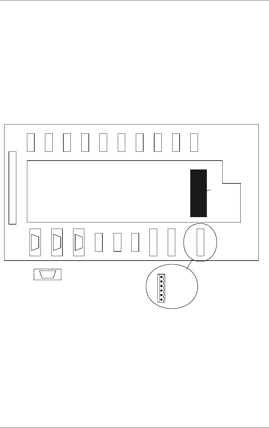
4.10 Digital Inputs and Outputs
Eight bidirectional digital channels (numbered 0-7) are located on the Connection Interface
board CI1210A as illustrated in Figure 4-10
Logic levels: TTL.
Input impedance: 560ohms.
Suitable female connectors are Weidemüller BLZ-5.08/4 or equivalent.
Figure4-10 Digital input/output connections.
TEMP
INDOOR TEMP
OUTDOOR AC
LEVEL ANALOG
CH.1 ANALOG
CH.2 ANALOG
CH.3 DIGITAL
PORT A DIGITAL
PORT B DIGITAL
PORT C DIGITAL
PORT D
TO MB1203
RS232 RS232 RS232 REMOTE
CONTROL
DC-LOOP DC-LOOP DME
LOCAL REMOTE 2 REMOTE 1 CH.1&2 CH.3&4
CI1210A
1 - USER_DIG5
2 - GND
3 - USER_DIG4
4 - GND
1
4
1
4
1
4
1
4
DIGITAL
PORT C
1 - USER_DIG3
2 - GND
3 - USER_DIG2
4 - GND
DIGITAL
PORT B
1 - USER_DIG1
2 - GND
3 - USER_DIG0
4 - GND
DIGITAL
PORT A
1 - USER_DIG7
2 - GND
3 - USER_DIG6
4 - GND
DIGITAL
PORT D
BATTERY
WARNING
HBK575-1
RADIO LINK
ELECTRICAL INSTALLATION
NORMARC 7033
4-27
©1999 Navia Aviation AS
INSTRUMENT LANDING SYSTEM
GENERAL DESCRIPTION
4.11 Battery Warning
Two inputs for main power supply failure (backup battery active) are sited on the CI1210A
connection interface board as illustrated in Figure 4-11
Logic levels: Normally high 5V or 0V =battery warning.
Input impedance: 10kohms.
Suitable female connectors are Weidemüller BLZ-5.08/4 or equivalent.
Figure4-11 Battery warning connections.
TEMP
INDOOR TEMP
OUTDOOR AC
LEVEL ANALOG
CH.1 ANALOG
CH.2 ANALOG
CH.3 DIGITAL
PORT A DIGITAL
PORT B DIGITAL
PORT C DIGITAL
PORT D
TO MB1203
RS232 RS232 RS232 REMOTE
CONTROL
DC-LOOP DC-LOOP DME
LOCAL REMOTE 2 REMOTE 1 CH.1&2 CH.3&4
BATTERY
WARNING
1 - BATT.WARN. CHARGER 1
2 - GND
3 - BATT.WARN. CHARGER 2
4 - GND
CI 1210A
1
4
BATTERY
WARNING
HBK602-2
RADIO LINK
NORMARC 7033
INSTRUMENT LANDING SYSTEM
GENERAL DESCRIPTION
ELECTRICAL INSTALLATION ©1999 Navia Aviation AS
4-28
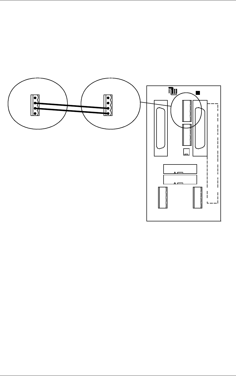
4.12 Remote control connections
The remote control is connected to the corresponding ILS by connecting the REMOTE CON-
TROL connector on Connection Interface CI1210 to P9 on Motherboard MB1346, as shown in
Figure 4-12.
Suitable female connectors are Weidemüller BLZ-5.08/4 or equivalent. 600 ohms cable
should be used.
Figure4-12 Remote control to ILS connection
The power supply to the remote control is connected according to Figure 4-13. The battery
charger is connected to P2 on the MB1347 - power supply motherboard. Output connector P3
on MB1347 is connected to input connector P4 on MB1346 - remote control motherboard.
Several MB1346's are serial linked by connecting P5 on one board to P4 on the next.
Suitable female connectors are Weidemüller BLZ-5.08/4 or equivalent.
REMOTE
CONTROL
1 - GND
2 - FSK_P
3 - FSK_N
4 - GND
J2 P3
P6
P7
P4
P5
P9
P10
P8
NORMARC
OPTO OUT
2-ALARM (E)
1-ALARM (C)
4-NORM (E)
5-WARN (C)
6-WARN (E)
7-STBAL (C)
8-STBAL (E)
3-NORM (C)
GND
5V
24V
V_DIM
GND
5V
24V
V_DIM
POWER OUT POWER IN
AUX IN/OUT
SLAVE
DIRECT
INTERLOCK
TXOFF
ALARM
LINE A
LINE B
RX A
RX B
TX A
TX B
SLAVE RS485
J1
ABC
1
5
30
20
25
15
10
ALT.LINK
MB1346
P9
1 - TXOFF
2 - ALARM
3 - LINE_A
4 - LINE_B
CI1210
on
corresponding
ILS
or
CI 1376
on
corresponding
Marker Beacon
HBK772-2

ELECTRICAL INSTALLATION
NORMARC 7033
4-29
©1999 Navia Aviation AS
INSTRUMENT LANDING SYSTEM
GENERAL DESCRIPTION
Figure4-13 Remote control power supply connections
J2 P3
P6
P7
P4
P5
P9
P10
P8
NORMARC
OPTO OUT
2-ALARM (E)
1-ALARM (C)
4-NORM (E)
5-WARN (C)
6-WARN (E)
7-STBAL (C)
8-STBAL (E)
3-NORM (C)
GND
5V
24V
V_DIM
GND
5V
24V
V_DIM
POWER OUT POWER IN
AUX IN/OUT
SLAVE
DIRECT
INTERLOCK
TXOFF
ALARM
LINE A
LINE B
RX A
RX B
TX A
TX B
SLAVE RS485
J1
ABC
1
5
30
20
25
15
10
ALT.LINK
MB1346
P2
P3
S1
GND
24V
POWER IN
GND
5V
24V
V_DIM
POWER OUT
V_DIM=24V
MB1347
NORMARC
30
25
20
15
10
5
1
AB
J1
J2 P3
P6
P7
P4
P5
P9
P10
P8
NORMARC
OPTO OUT
2-ALARM (E)
1-ALARM (C)
4-NORM (E)
5-WARN (C)
6-WARN (E)
7-STBAL (C)
8-STBAL (E)
3-NORM (C)
GND
5V
24V
V_DIM
GND
5V
24V
V_DIM
POWER OUT POWER IN
AUX IN/OUT
SLAVE
DIRECT
INTERLOCK
TXOFF
ALARM
LINE A
LINE B
RX A
RX B
TX A
TX B
SLAVE RS485
J1
ABC
1
5
30
20
25
15
10
ALT.LINK
MB1346
From
24VDC
power
supply
HBK773-1

NORMARC 7033
INSTRUMENT LANDING SYSTEM
GENERAL DESCRIPTION
ELECTRICAL INSTALLATION ©1999 Navia Aviation AS
4-30
4.13 Remote slave connection
The remote slave panel SF1344 is connected to the corresponding remote control's mother-
board by connecting P3 on MB1346 to P1 on SF1344. P10 on MB1346 is not used. See Fig-
ure 4-14.
Suitable connectors are standard 25 pins female DSUB (Harting 0967 025 0442 and 0967 225
4704 or equivalent), connected by a 10 wire 1:1 cable.
Figure4-14 Remote slave connection
J2 P3
P6
P7
P4
P5
P9
P10
P8
NORMARC
OPTO OUT
2-ALARM (E)
1-ALARM (C)
4-NORM (E)
5-WARN (C)
6-WARN (E)
7-STBAL (C)
8-STBAL (E)
3-NORM (C)
GND
5V
24V
V_DIM
GND
5V
24V
V_DIM
POWER OUT POWER IN
AUX IN/OUT
SLAVE
DIRECT
INTERLOCK
TXOFF
ALARM
LINE A
LINE B
RX A
RX B
TX A
TX B
SLAVE RS485
J1
ABC
1
5
30
20
25
15
10
ALT.LINK
MB1346
To P1
on
SF1344
1
13
14
25
1 - GND
2 - ALARM
3 - WARNING
4 - NORMAL
7 - GND
15 - V24P
19 - ON_OFF
21 - SILENCE
23 - INTERLOCK (if used)
25 - BUZZER
1:1
HBK 774-1
ELECTRICAL INSTALLATION
NORMARC 7033
4-31
©1999 Navia Aviation AS
INSTRUMENT LANDING SYSTEM
GENERAL DESCRIPTION
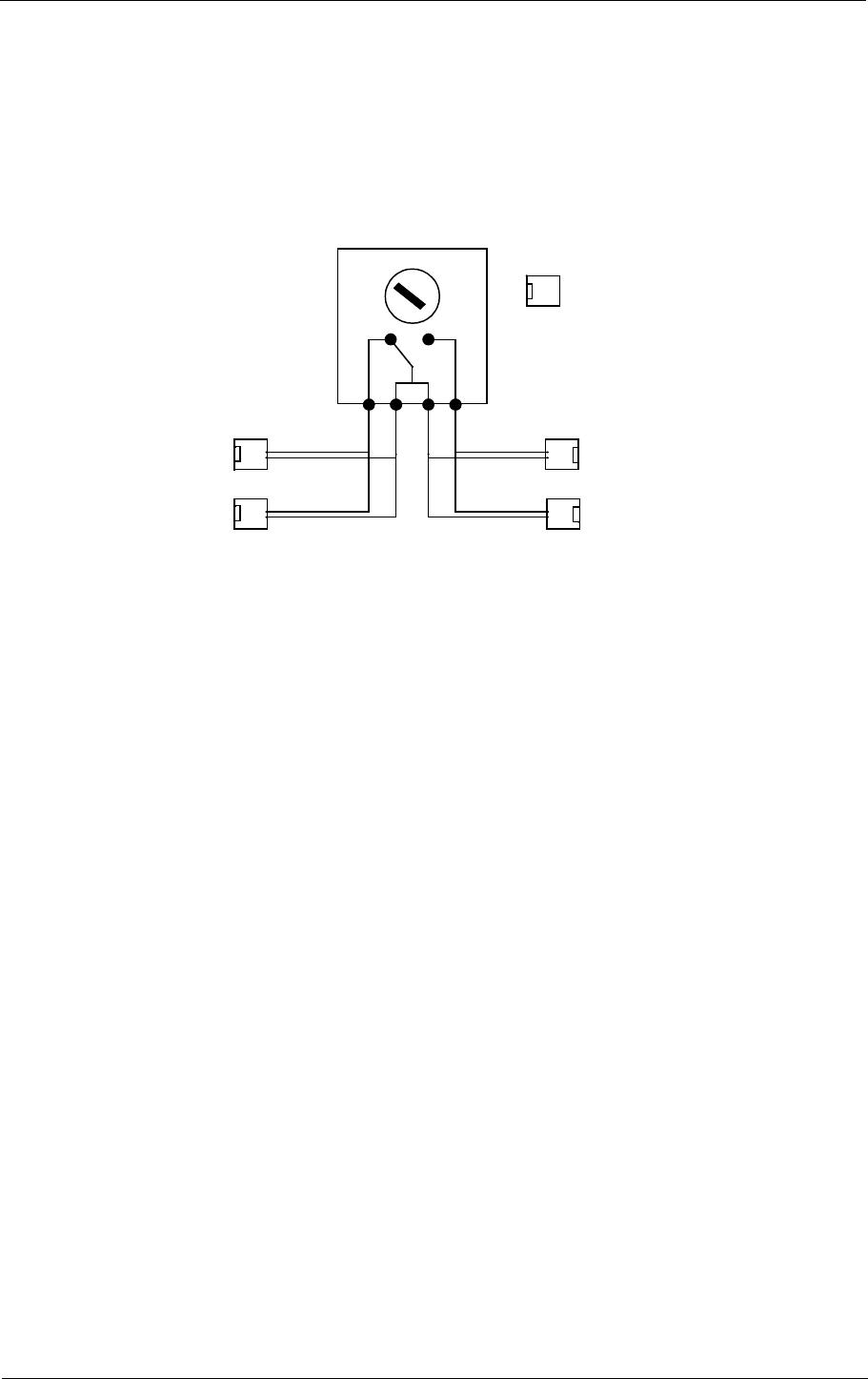
4.14 Interlock switch connection
The interlock switch is either connected to P8 on MB1346 (remote control motherboard) or to
P2 on SF1344 (remote slave panel), see Figure 4-15.
Figure4-15 Interlock switch connection
Note:
When MB1346A is used with Remote Control Assembly RCA1240C or D and Interlock func-
tion is not used (connected), a jumper plug must be installed in P8 (or P2).
2
1
MB1346 / P8
OR
SF1344 / P2
INTERLOCK
SWITCH
RWYA RWYB
2
1
1
2
1
2
INTERLOCK
GND
1
2
54 21
LLZ runway A
GP runway A
LLZ runway B
GP runway B
HBK775-2