Leidos Innovations NORMARC7033 7033 Dual Frequency Glide Path User Manual General Description 7011
Lockheed Martin Air Traffic Management 7033 Dual Frequency Glide Path General Description 7011
Contents
- 1. Normarc 7033 Instrument Landing System Operating Manual
- 2. Normarc 7033 ILS Technical Handbook
- 3. Normarc ILS Installation and Commissioning Hanbook Vol 1
- 4. Normarc ILS Installation and Commissioning Hanbook Vol 2
- 5. Normarc ILS Installation and Commissioning Hanbook Vol 1 and 2
- 6. Normarc ILS General Description
- 7. Normarc 7033 Instrument Landing System Operation Manual
- 8. Normarc ILS Installation and Commissioning Handbook Vol 1
- 9. Normarc ILS Installation and Commissioning Handbook Vol 2
- 10. Normarc ILS Installation and Commissioning Handbook Vol 1 and 2
- 11. Normarc 7033 ILS General Description
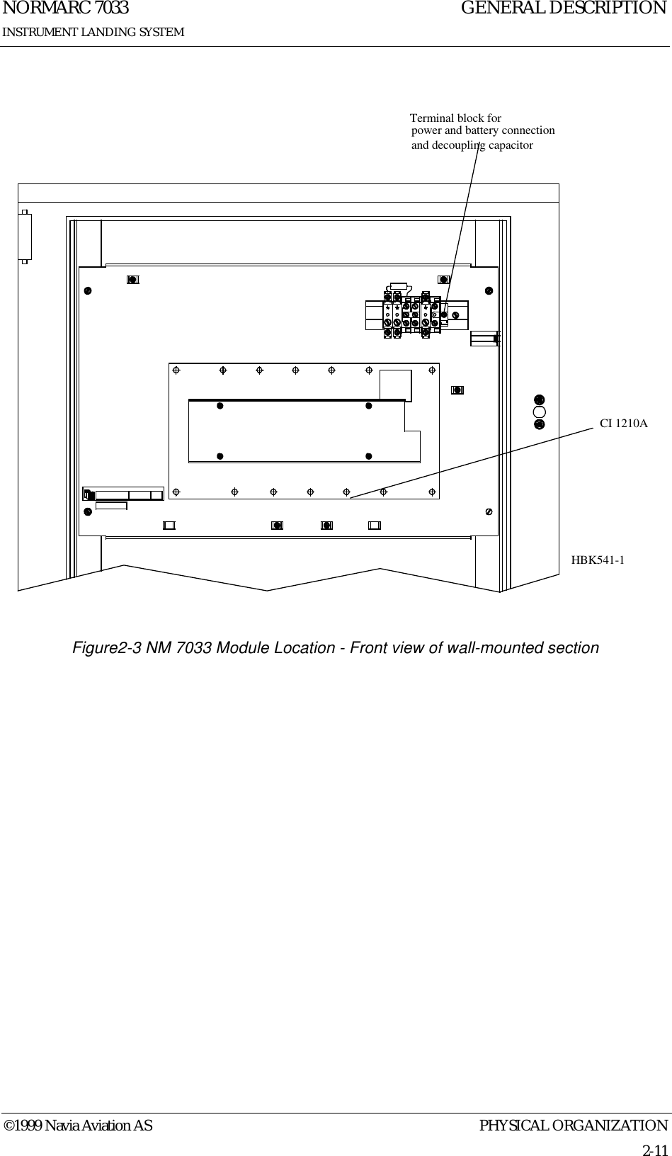
Normarc ILS General Description

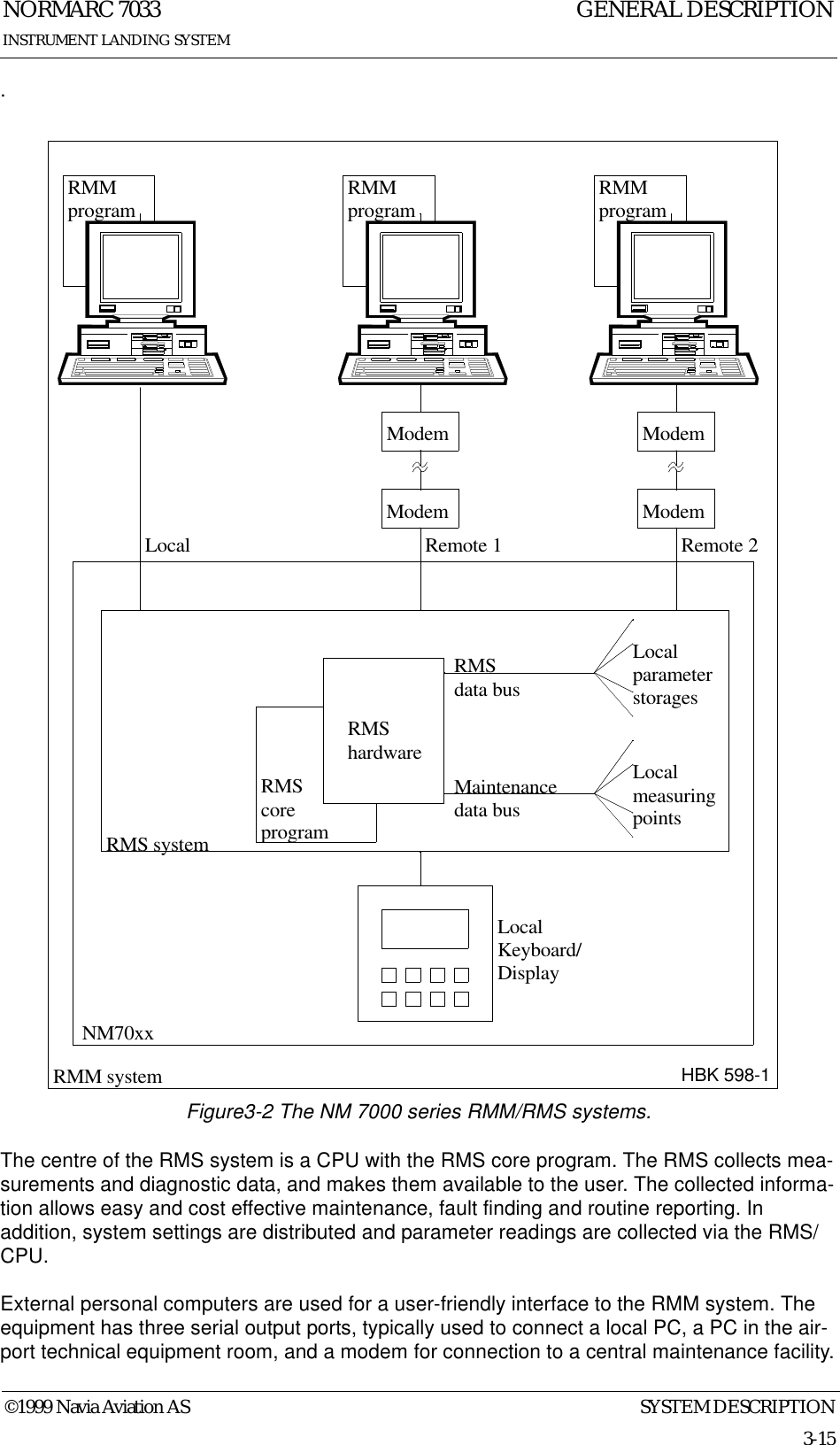
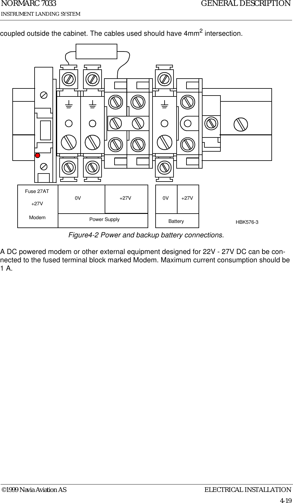
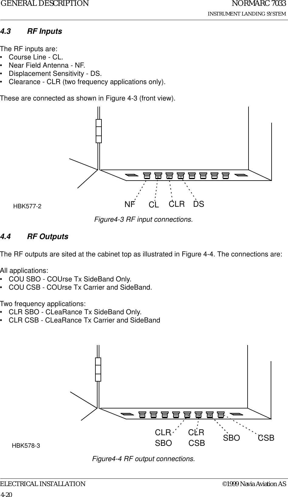
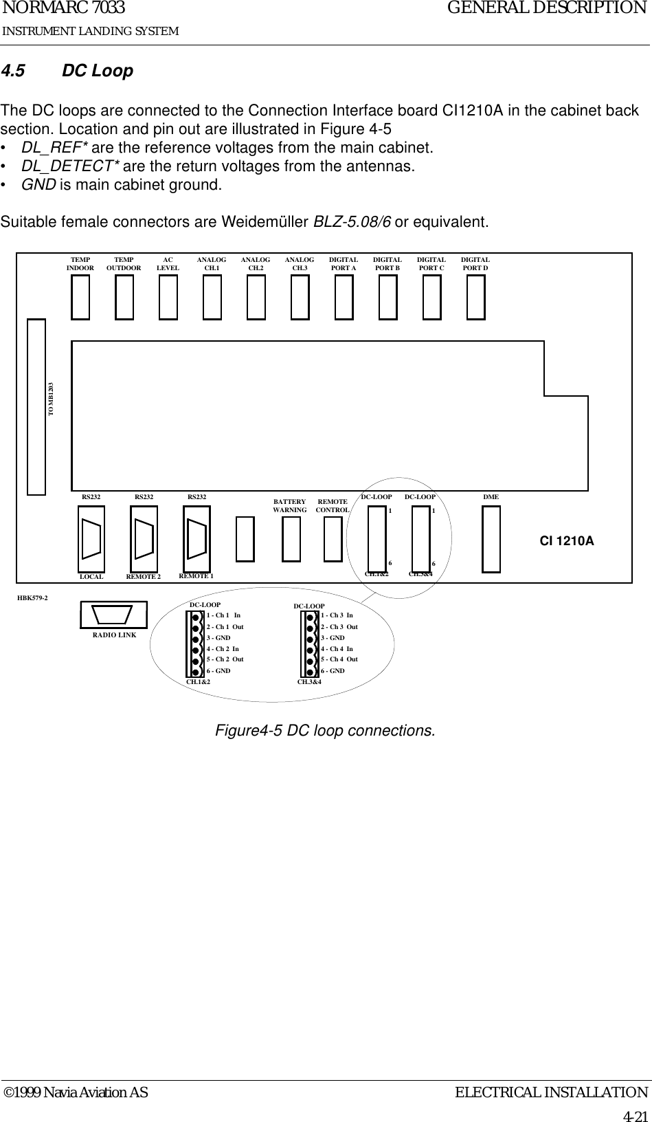
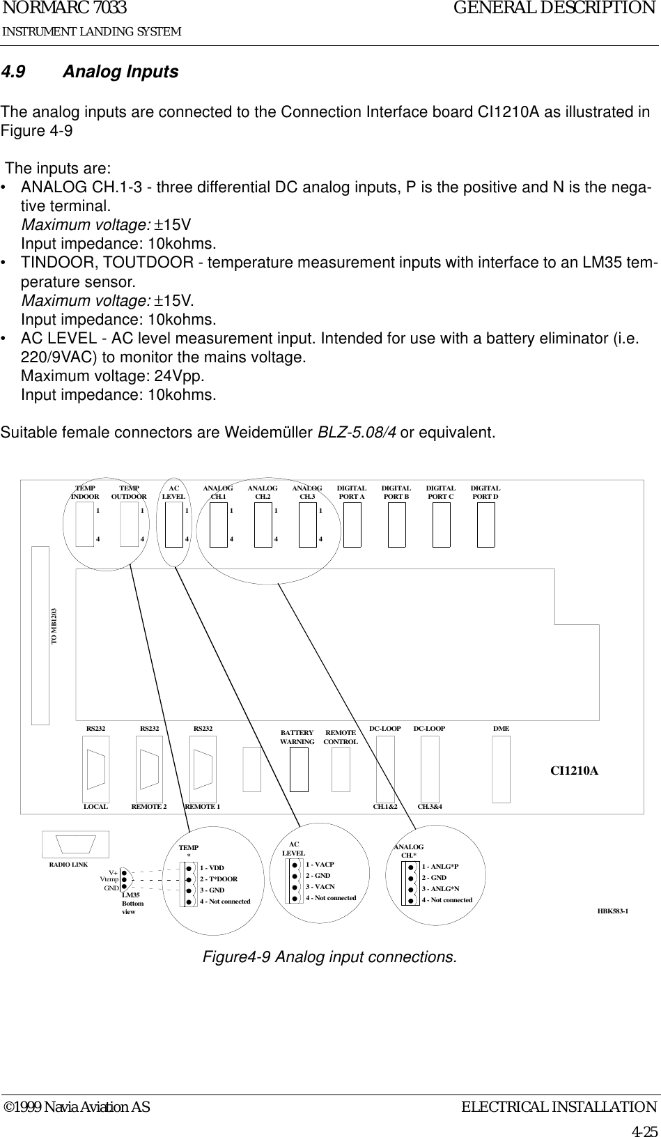
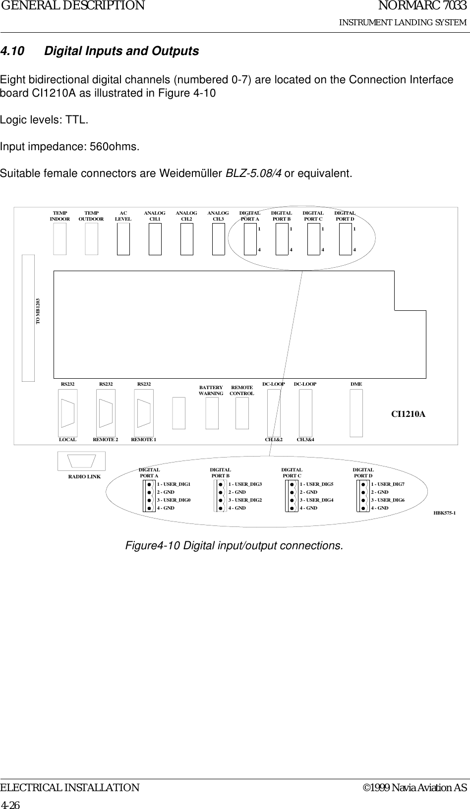
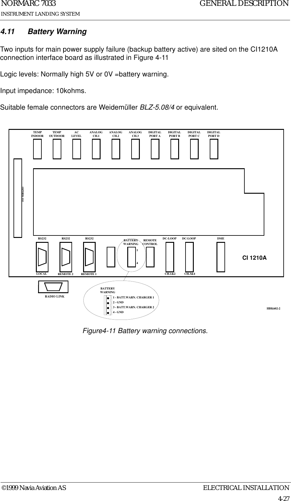
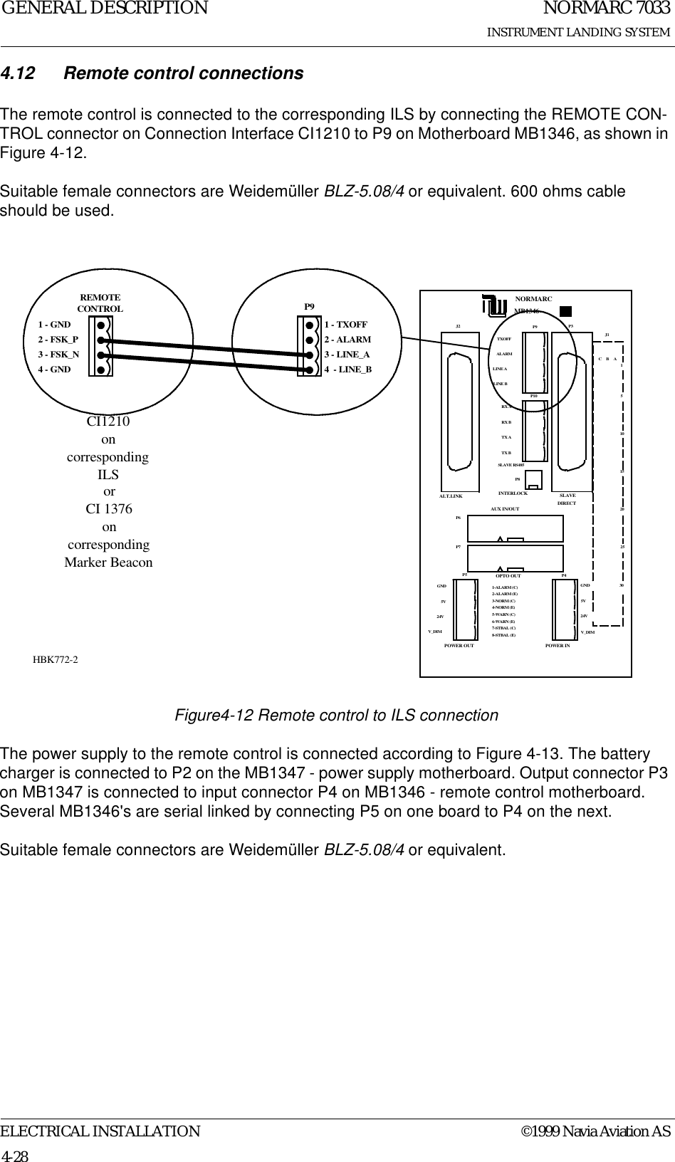
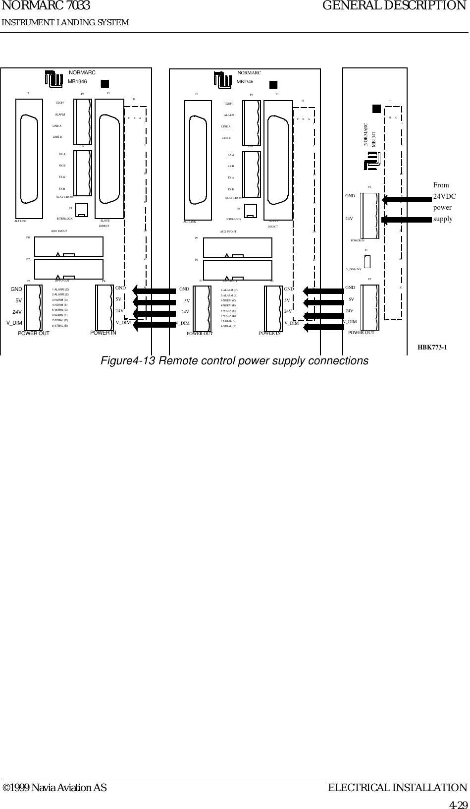
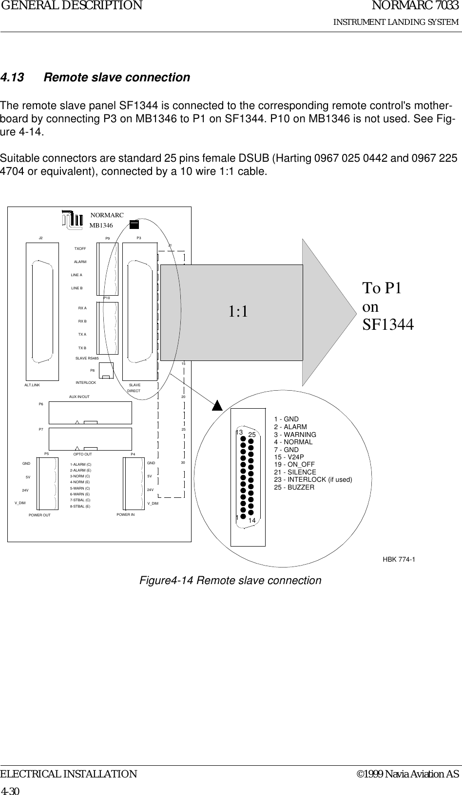
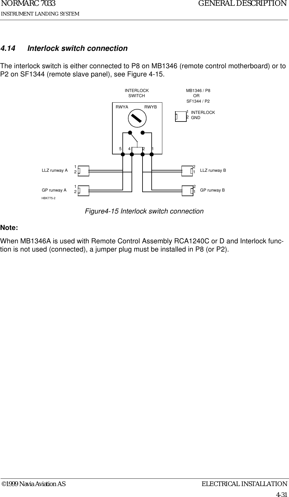
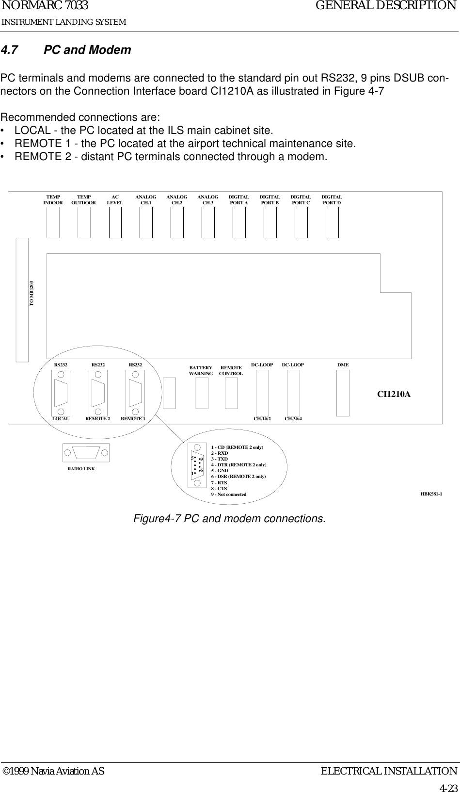
![NORMARC 7033INSTRUMENT LANDING SYSTEMGENERAL DESCRIPTIONELECTRICAL INSTALLATION ©1999 Navia Aviation AS4-224.6 Remote ControlThe remote control is connected to the Connection Interface board CI1210A as illustrated in Figure 4-6. The connection of the remote control, remote slave panel and interlock switch is done at the remote control site and covered in chapter 4.12 - 4.14•FSK_[P,N] is the modem line pair.•GND is main cabinet ground.For normal FSK modem operation the straps S9-11 on CI1210A should be mounted.A suitable female connector is Weidemüller BLZ-5.08/4 or equivalent.Figure4-6 Remote control connection.TEMPINDOOR TEMPOUTDOOR ACLEVEL ANALOGCH.1 ANALOGCH.2 ANALOGCH.3 DIGITALPORT A DIGITALPORT B DIGITALPORT C DIGITALPORT DTO MB1203RS232 RS232 RS232 REMOTECONTROLDC-LOOP DC-LOOP DMELOCAL REMOTE 2 REMOTE 1 CH.1&2 CH.3&4REMOTECONTROL1 - GND2 - FSK_P3 - FSK_N4 - GNDCI1210A14S9-14BATTERYWARNINGHBK580-1RADIO LINK](https://usermanual.wiki/Leidos-Innovations/NORMARC7033.Normarc-ILS-General-Description/User-Guide-90104-Page-30.png)
![NORMARC 7033INSTRUMENT LANDING SYSTEMGENERAL DESCRIPTIONELECTRICAL INSTALLATION ©1999 Navia Aviation AS4-244.8 DME Distance Measurement Equipment DME is connected to the Connection Interface board CI1210A as illustrated in Figure 4-8•ACT_DME[P,N] is the positive and negative terminal of the DME active signal from the DME, respectively.•IN_DME[P,N] is the positive and negative terminal of the morse code envelope signal from the DME, respectively.•OUT_DME[P,N] is the positive and negative terminal of the morse code envelope signal to the DME, respectively.A suitable female connector is Weidemüller BLZ-5.08/6 or equivalent.Figure4-8 DME connections.TEMPINDOORTEMPOUTDOORACLEVELANALOGCH.1ANALOGCH.2ANALOGCH.3DIGITALPORT ADIGITALPORT BDIGITALPORT CDIGITALPORT DTO MB1203RS232 RS232 RS232 REMOTECONTROLDC-LOOP DC-LOOP DMELOCAL REMOTE 2 REMOTE 1 CH.1&2 CH.3&41 - ACT_DMEP2 - ACT_DMEN3 - IN_DMEP4 - IN_DMENCI1210A16S1-8DME5 - OUT_DMEP6 - OUT_DMENBATTERYWARNINGHBK582-1RADIO LINK](https://usermanual.wiki/Leidos-Innovations/NORMARC7033.Normarc-ILS-General-Description/User-Guide-90104-Page-32.png)