Leidos Innovations NORMARC7033 7033 Dual Frequency Glide Path User Manual
Lockheed Martin Air Traffic Management 7033 Dual Frequency Glide Path
Contents
- 1. Normarc 7033 Instrument Landing System Operating Manual
- 2. Normarc 7033 ILS Technical Handbook
- 3. Normarc ILS Installation and Commissioning Hanbook Vol 1
- 4. Normarc ILS Installation and Commissioning Hanbook Vol 2
- 5. Normarc ILS Installation and Commissioning Hanbook Vol 1 and 2
- 6. Normarc ILS General Description
- 7. Normarc 7033 Instrument Landing System Operation Manual
- 8. Normarc ILS Installation and Commissioning Handbook Vol 1
- 9. Normarc ILS Installation and Commissioning Handbook Vol 2
- 10. Normarc ILS Installation and Commissioning Handbook Vol 1 and 2
- 11. Normarc 7033 ILS General Description
Normarc 7033 ILS Technical Handbook


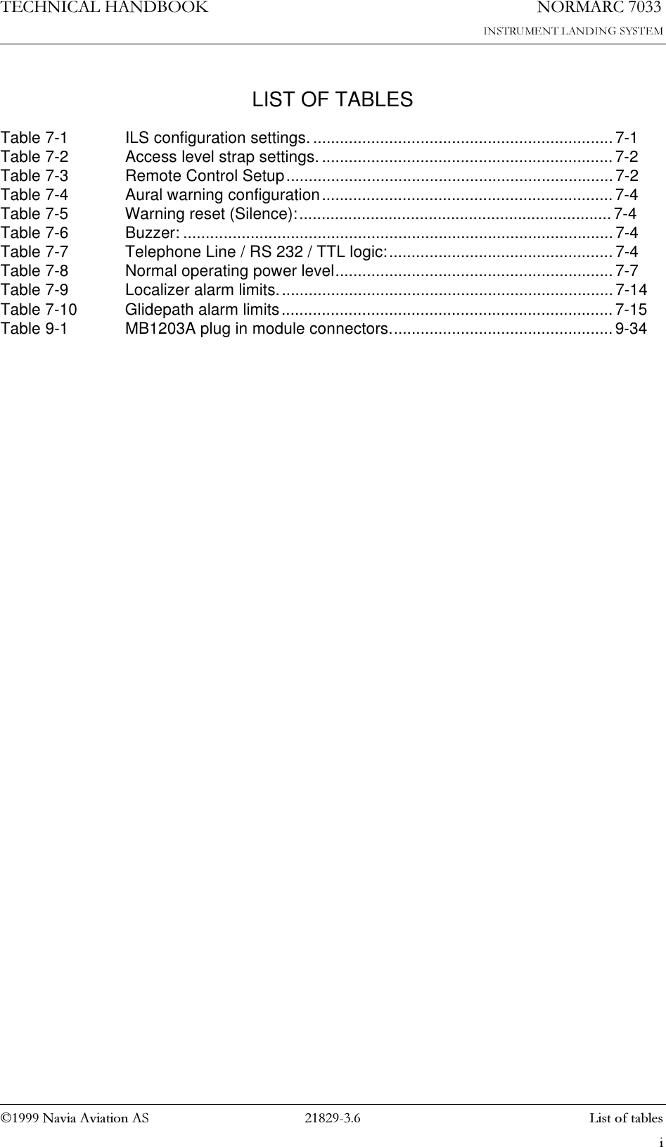

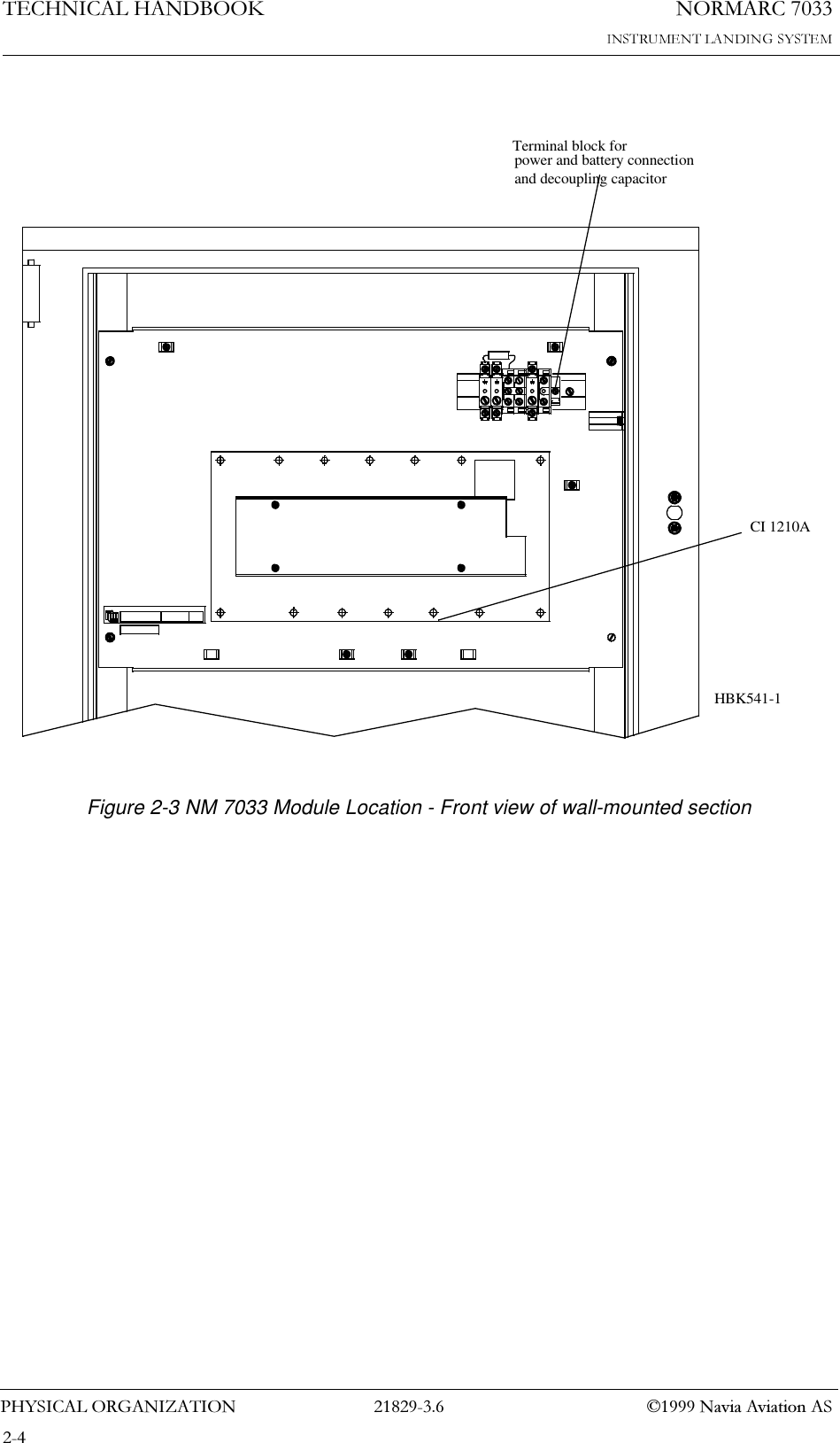
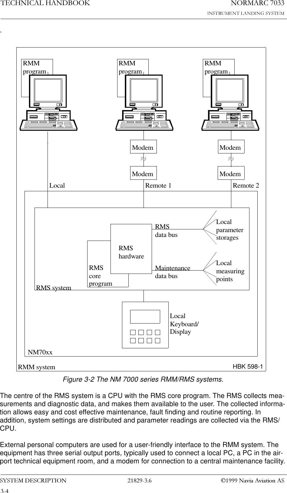
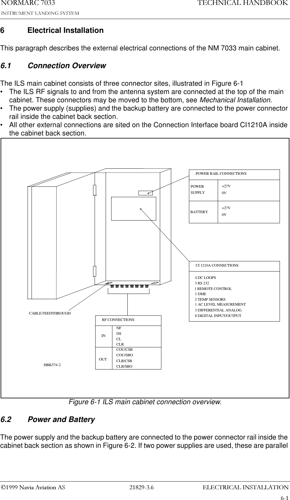
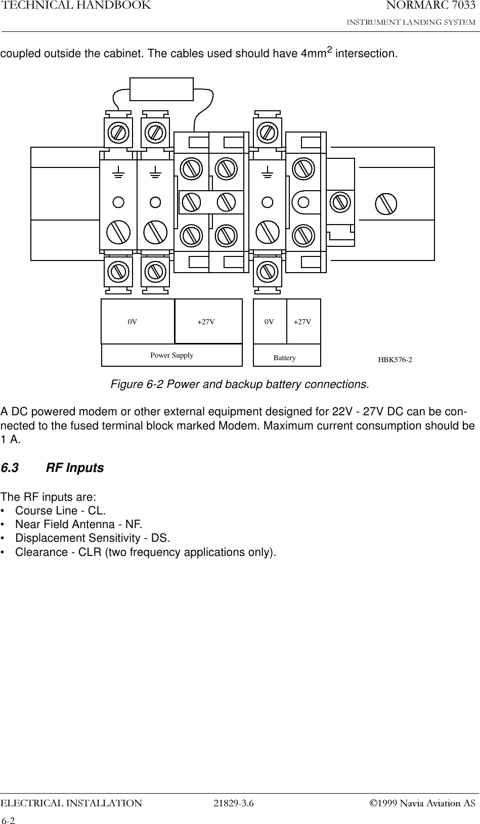
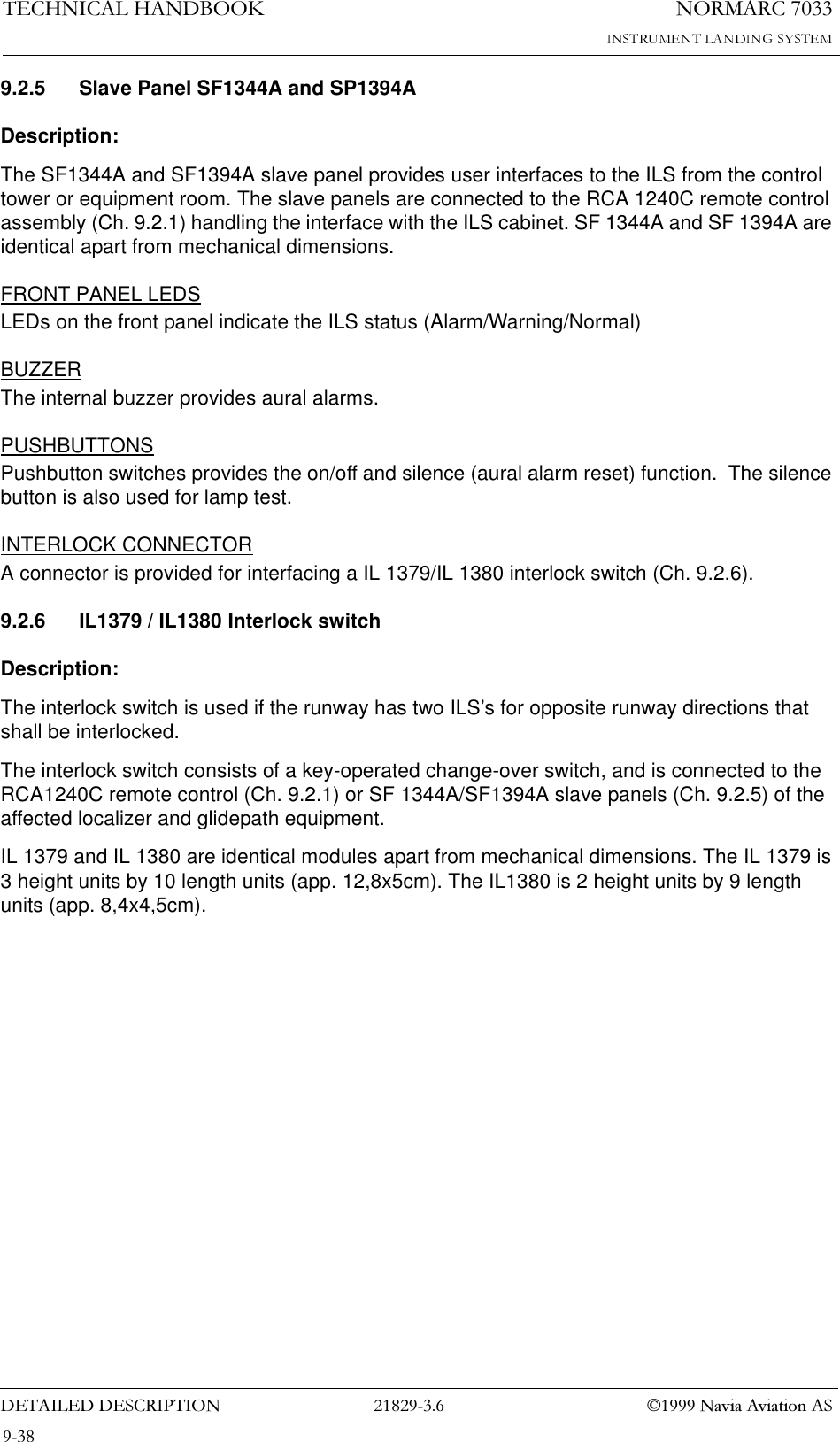
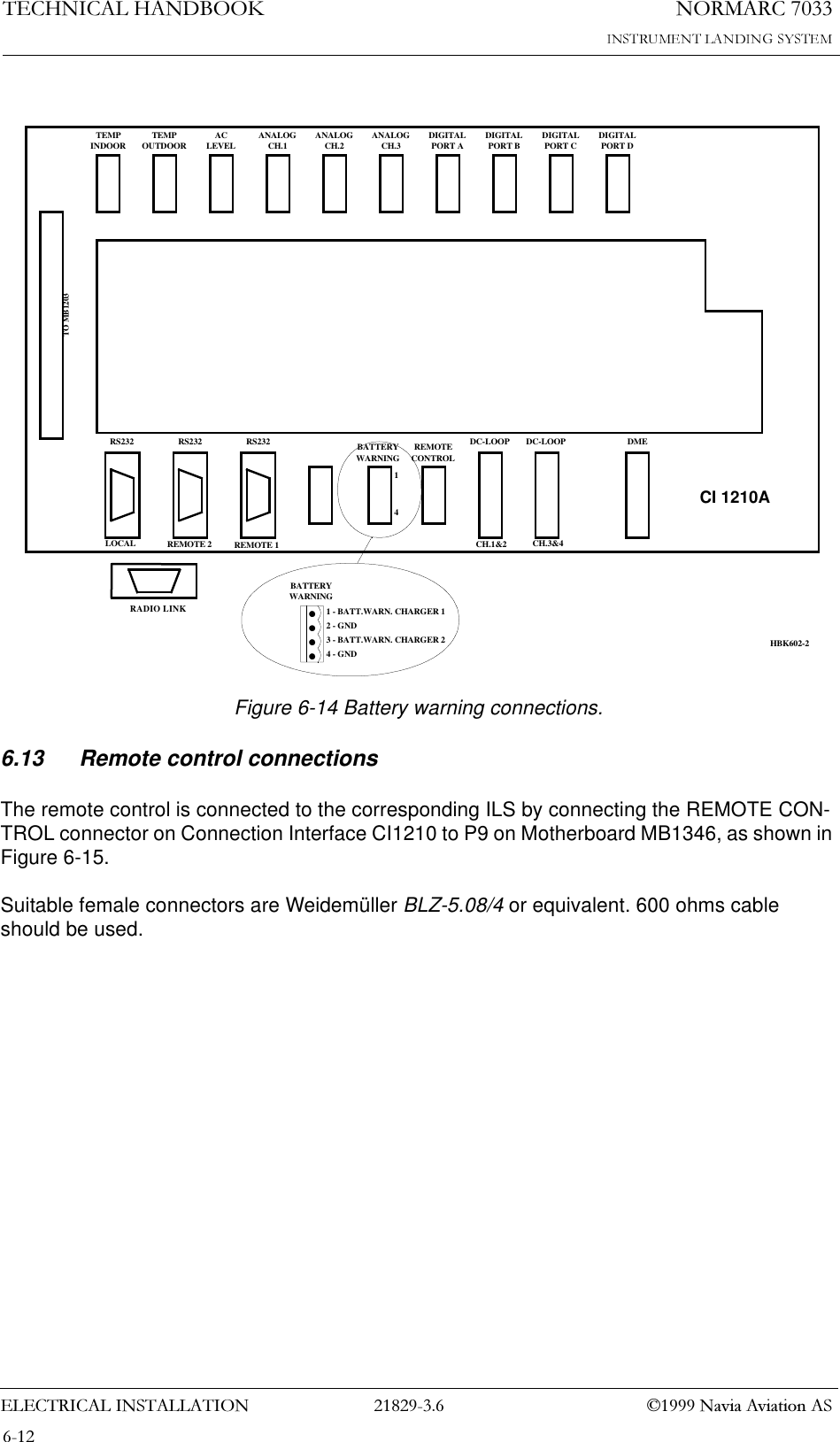
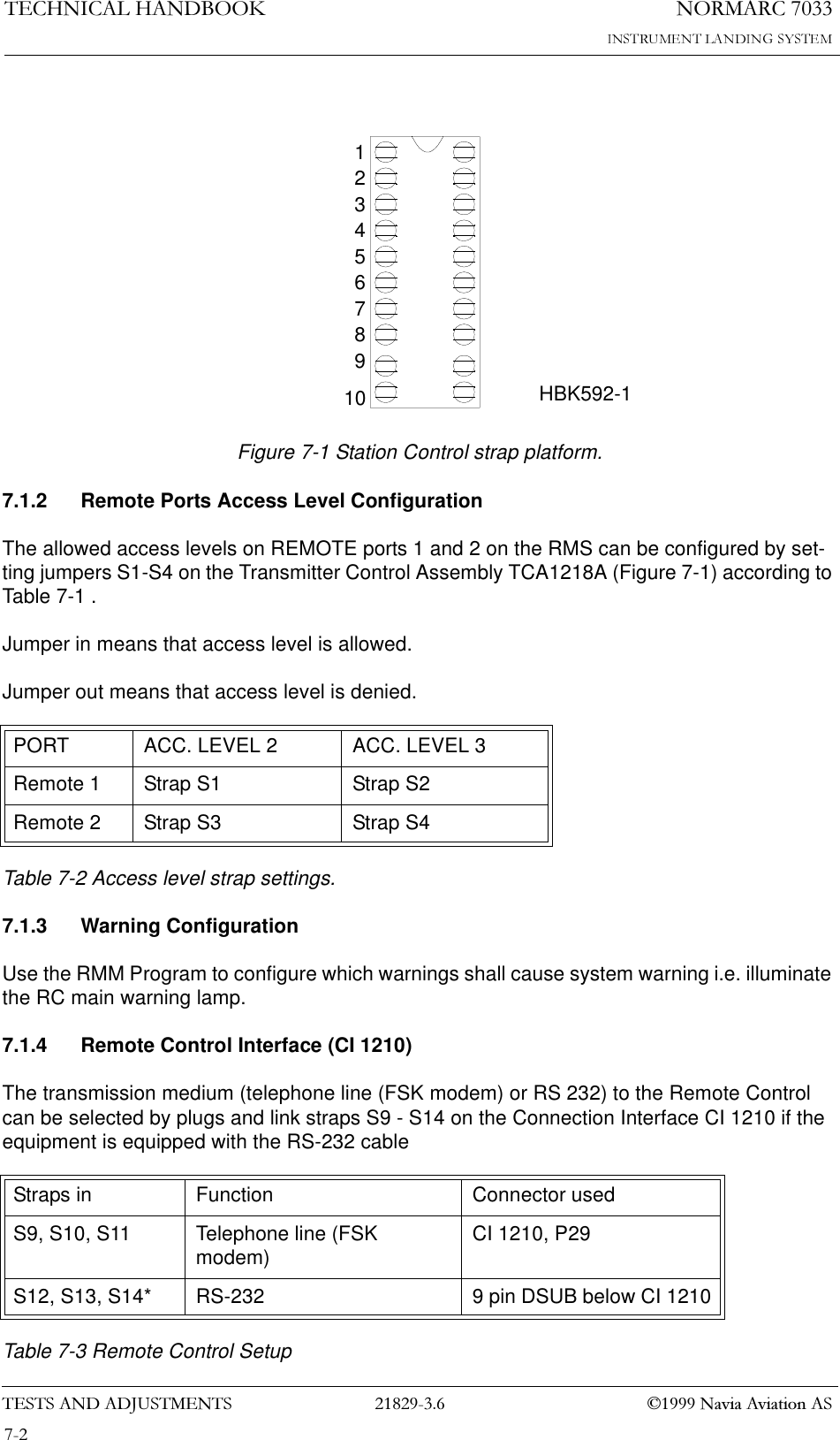
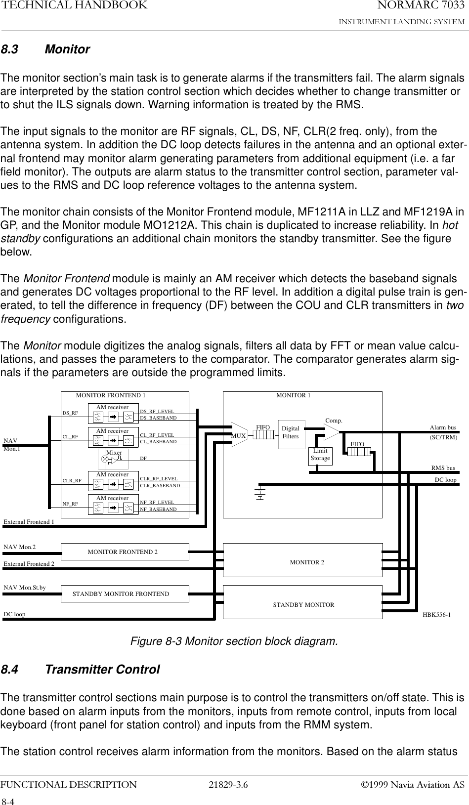
![(/(&75,&$/,167$//$7,211250$5&1DYLD$YLDWLRQ$67(&+1,&$/+$1'%22.6.6 Remote ControlThe remote control is connected to the Connection Interface board CI1210A as illustrated in Figure 6-6. The connection of the remote control, remote slave panel and interlock switch is done at the remote control site and covered in chapter 6.13 - 6.16•FSK_[P,N] is the modem line pair.•GND is main cabinet ground.For normal FSK modem operation the straps S9-11 on CI1210A should be mounted.A suitable female connector is Weidemüller BLZ-5.08/4 or equivalent.Figure 6-6 Remote control connection.TEMPINDOOR TEMPOUTDOOR ACLEVEL ANALOGCH.1 ANALOGCH.2 ANALOGCH.3 DIGITALPORT A DIGITALPORT B DIGITALPORT C DIGITALPORT DTO MB1203RS232 RS232 RS232 REMOTECONTROLDC-LOOP DC-LOOP DMELOCAL REMOTE 2 REMOTE 1 CH.1&2 CH.3&4REMOTECONTROL1 - GND2 - FSK_P3 - FSK_N4 - GND14S9-14BATTERYWARNINGHBK580-1RADIO LINK](https://usermanual.wiki/Leidos-Innovations/NORMARC7033.Normarc-7033-ILS-Technical-Handbook/User-Guide-90100-Page-37.png)
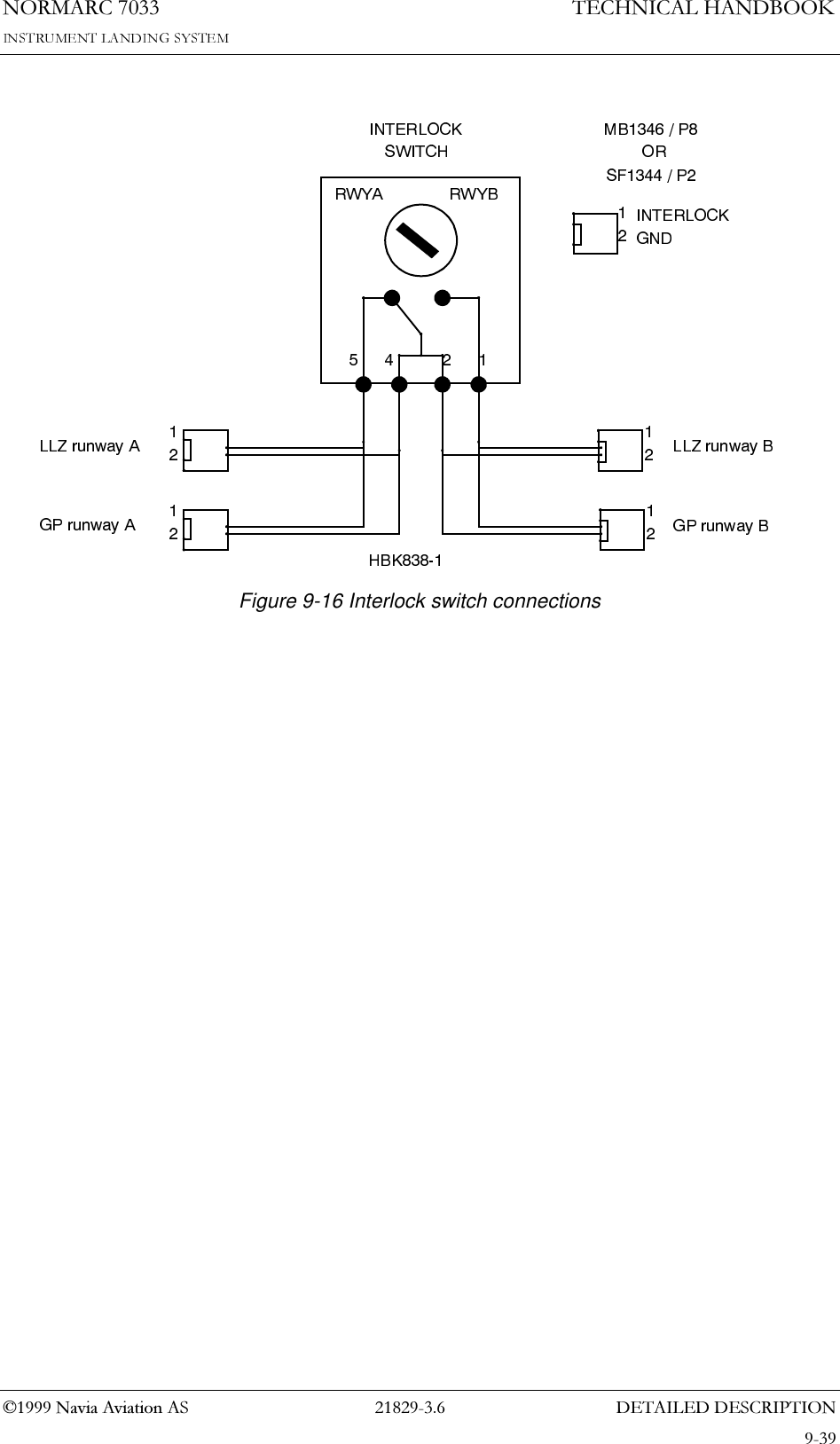
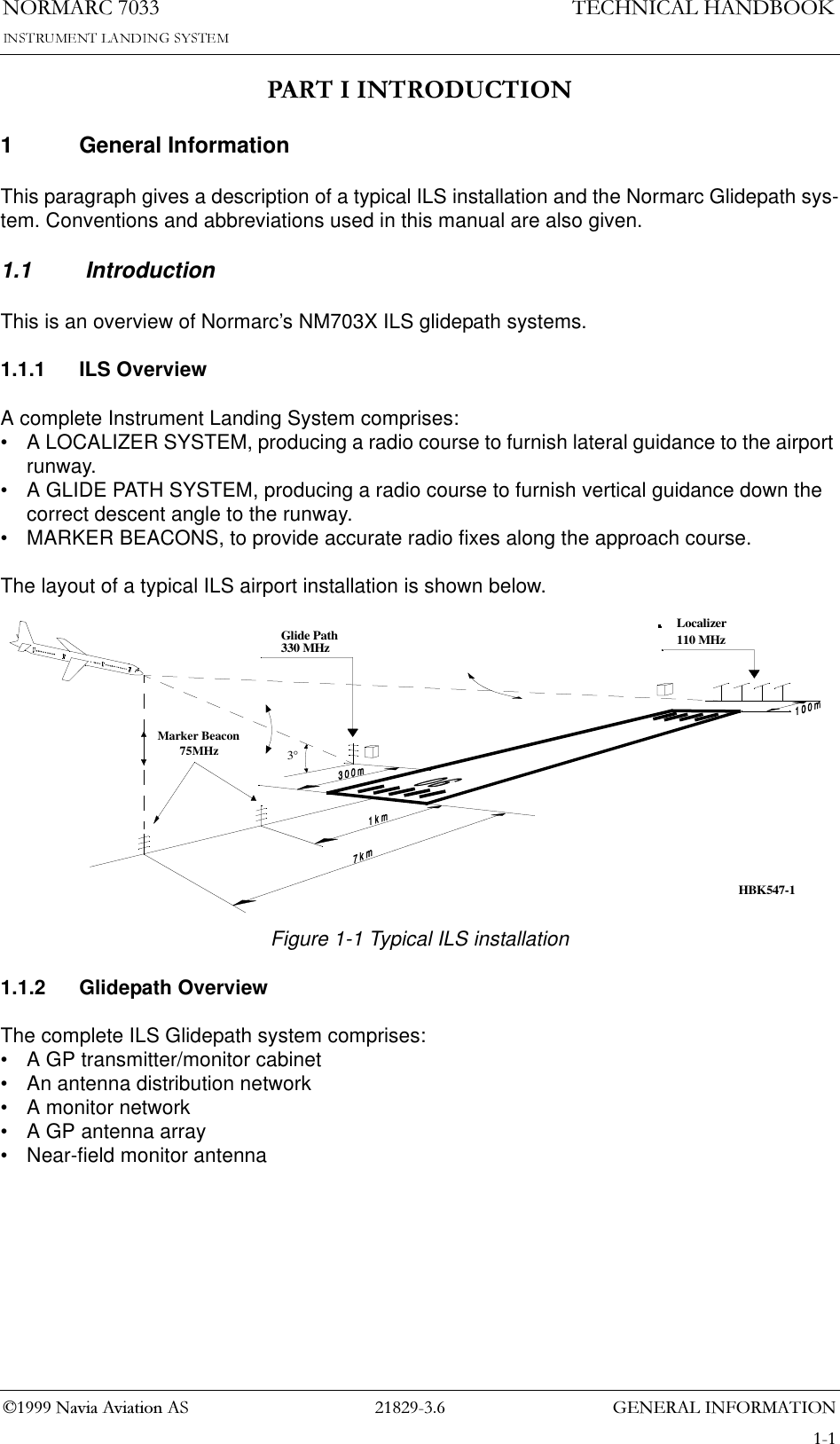
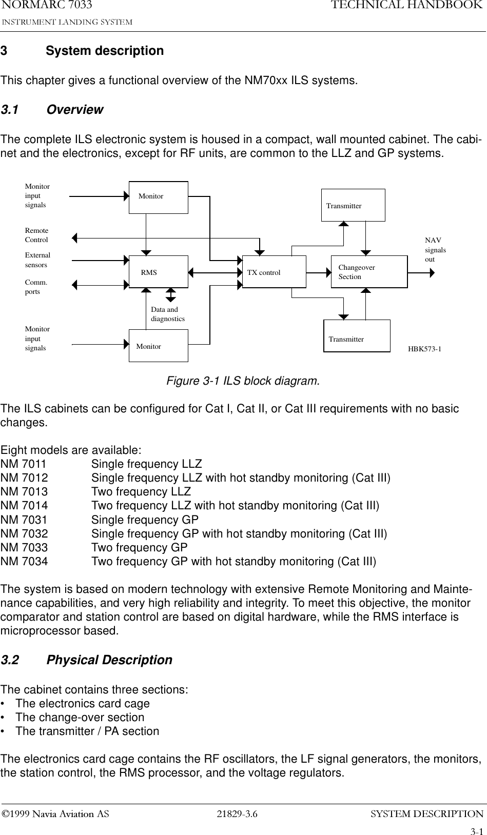
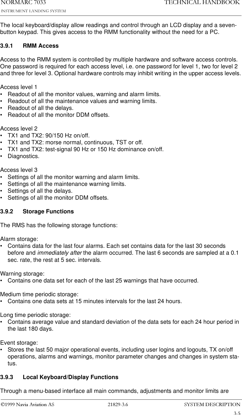
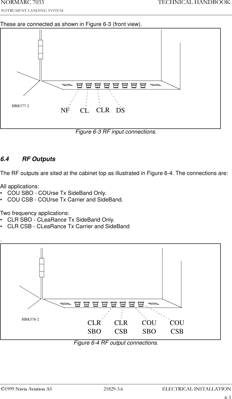
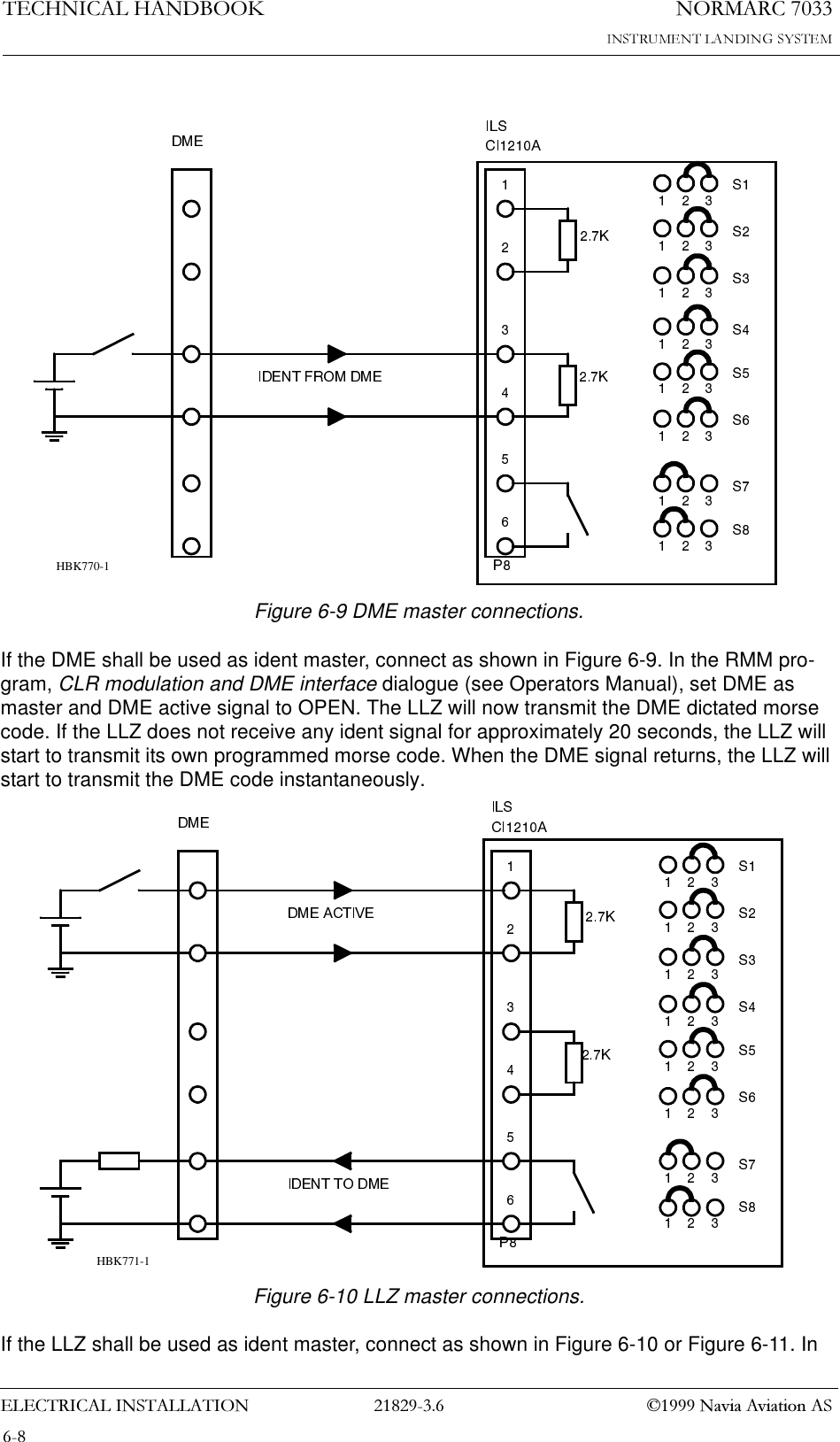
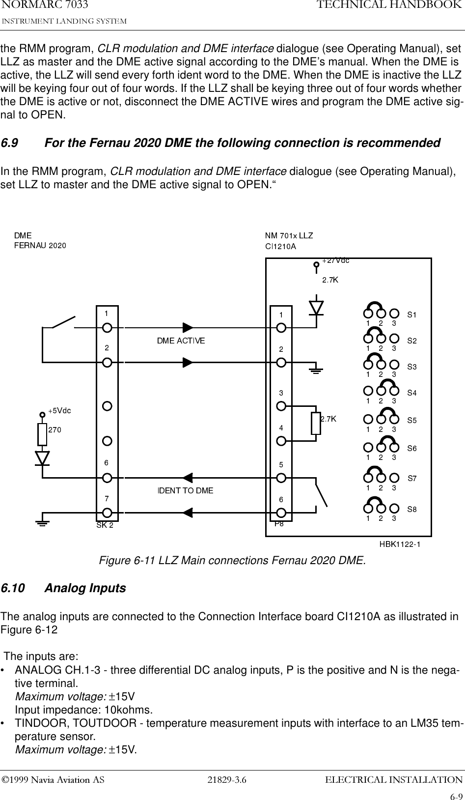
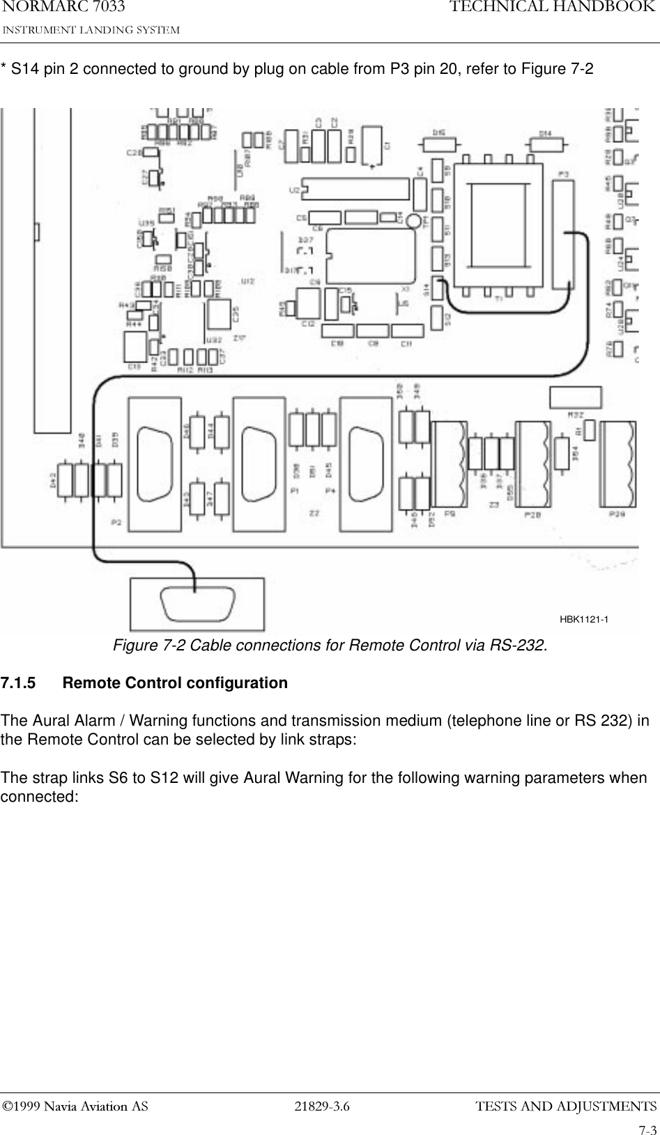
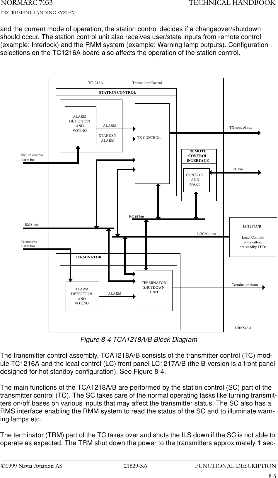
![(/(&75,&$/,167$//$7,211250$5&1DYLD$YLDWLRQ$67(&+1,&$/+$1'%22.6.8 DME (localizer only)Distance Measurement Equipment DME is connected to the Connection Interface board CI1210A as illustrated in Figure 6-8•ACT_DME[P,N] is the positive and negative terminal of the DME active signal from the DME, respectively.•IN_DME[P,N] is the positive and negative terminal of the morse code envelope signal from the DME, respectively.•OUT_DME[P,N] is the positive and negative terminal of the morse code envelope signal to the DME, respectively.A suitable female connector is Weidemüller BLZ-5.08/6 or equivalent.Figure 6-8 DME connections.TEMPINDOORTEMPOUTDOORACLEVELANALOGCH.1ANALOGCH.2ANALOGCH.3DIGITALPORT ADIGITALPORT BDIGITALPORT CDIGITALPORT DTO MB1203RS232 RS232 RS232 REMOTECONTROLDC-LOOP DC-LOOP DMELOCAL REMOTE 2 REMOTE 1 CH.1&2 CH.3&41 - ACT_DMEP2 - ACT_DMEN3 - IN_DMEP4 - IN_DMENCI1210A16S1-8DME5 - OUT_DMEP6 - OUT_DMENBATTERYWARNINGHBK582-1RADIO LINK](https://usermanual.wiki/Leidos-Innovations/NORMARC7033.Normarc-7033-ILS-Technical-Handbook/User-Guide-90100-Page-39.png)
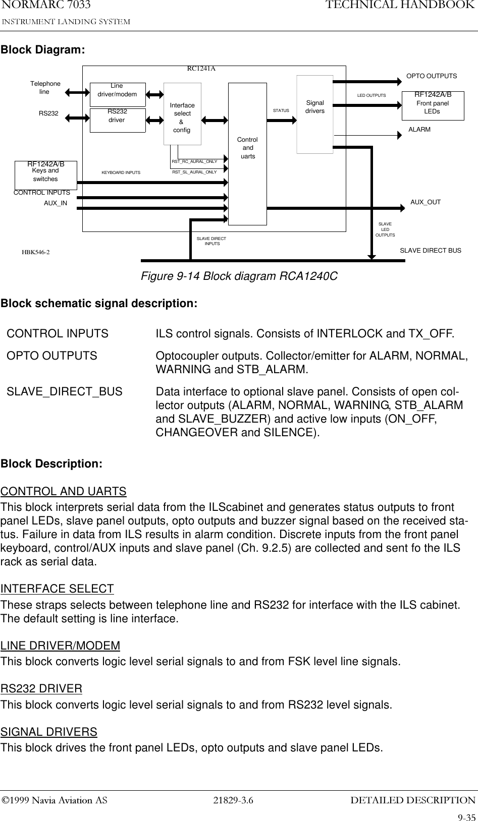
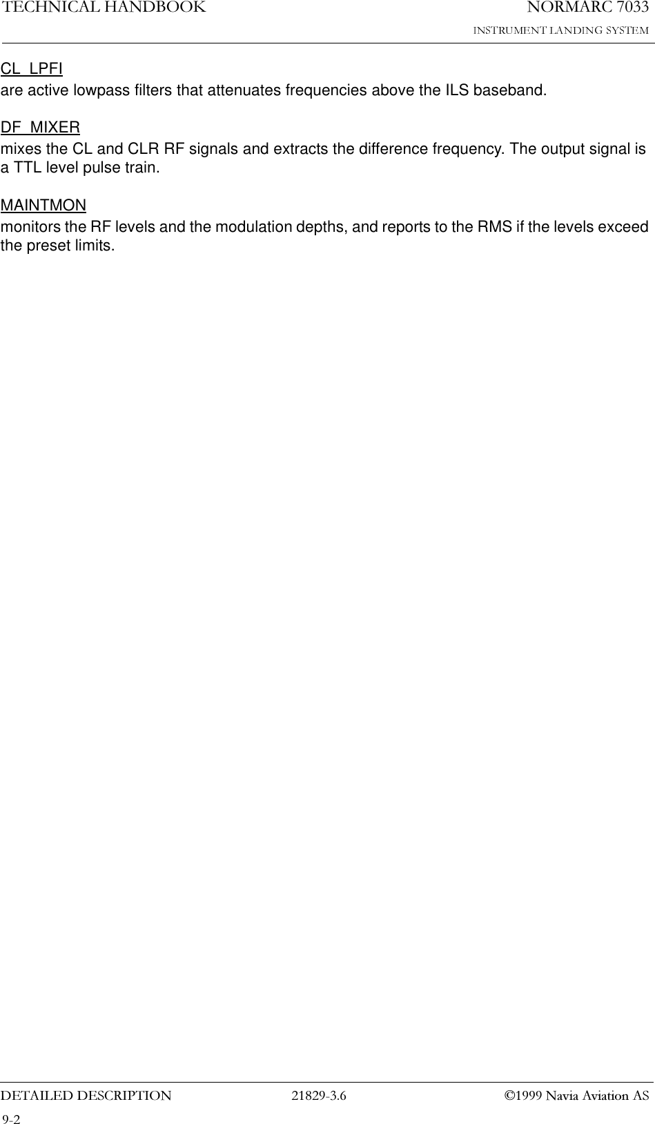
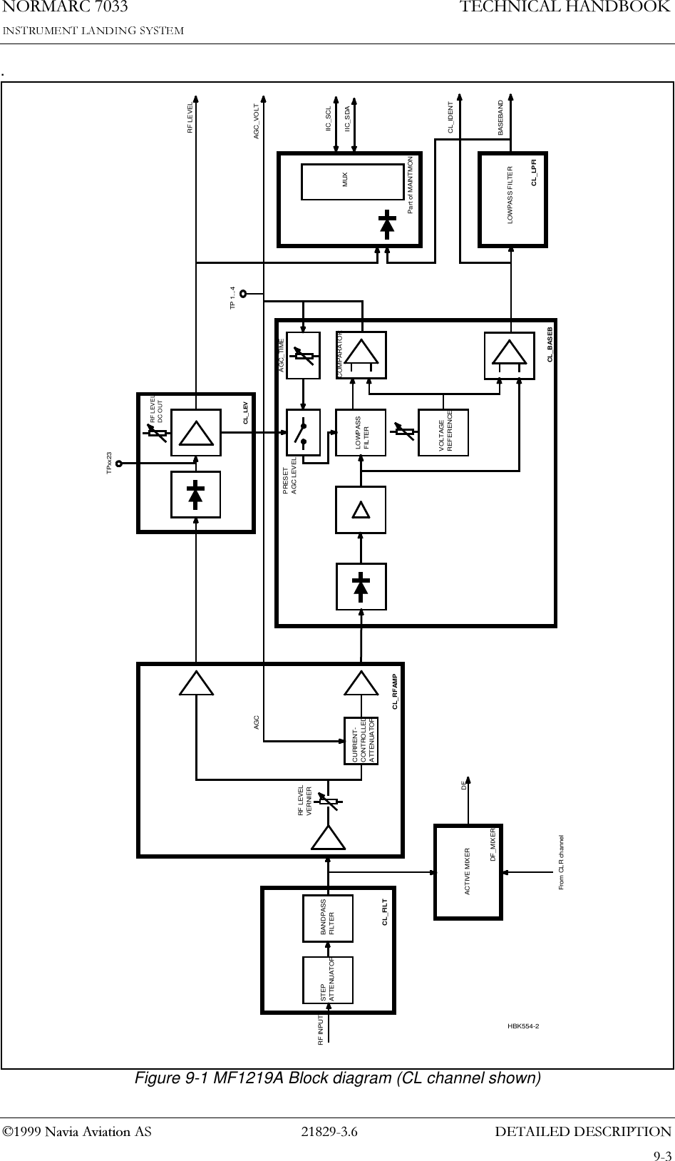
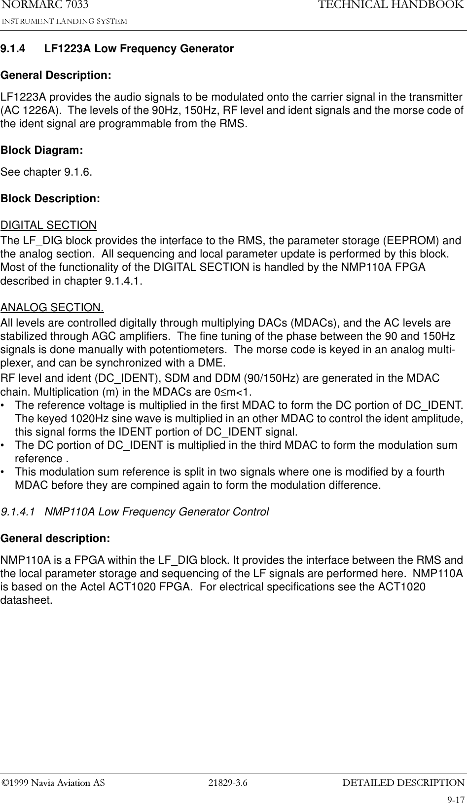
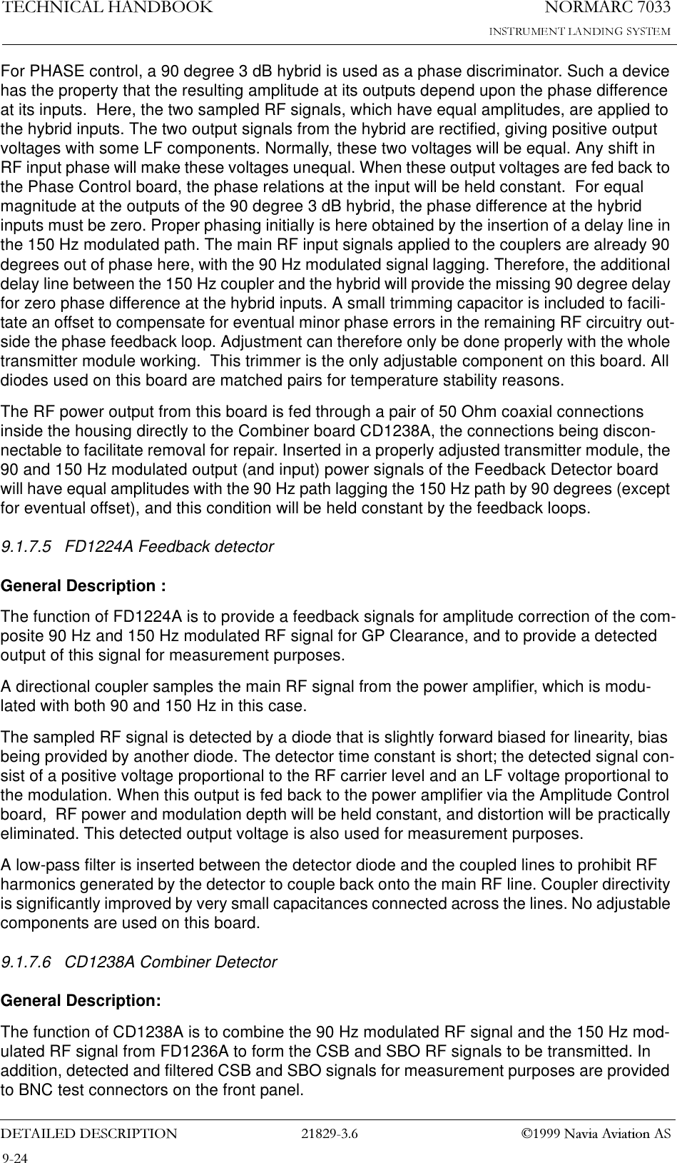
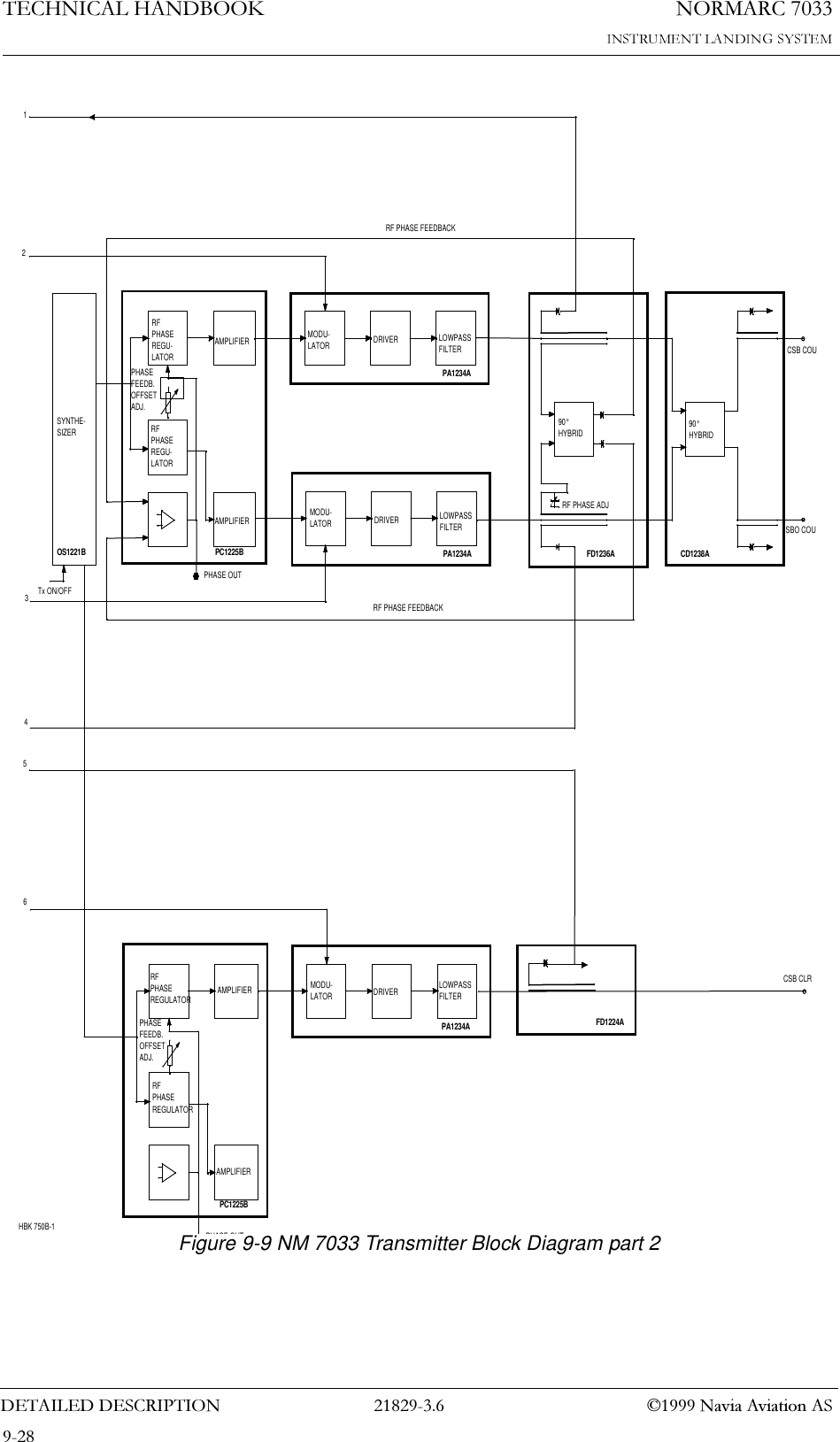
!['(7$,/(''(6&5,37,211250$5&7(&+1,&$/+$1'%22.1DYLD$YLDWLRQ$69 Detailed descriptionThis chapter gives a detailed description of the assemblies and modules in the NM7033.Notations in the block diagrams: ~ - Active low signal.[7:0] - Signal bus numbering system. Here, an eight bits bus, numbered from seven down to zero.9.1 Main CabinetThe following paragraphs describe the electronics modules located in the main cabinet.9.1.1 MF1219A Glidepath Monitor FrontendGeneral Description:The MF1219A module demodulates the ILS RF signals from the antenna system, and passes baseband and RF level signals, and a digital pulstrain representing the difference in frequency (DF) between the CL and CLR signals, to the monitor MO1212A (chapter 9.1.2). The CLR channel and DF circuit are used in two frequency systems only.Block Diagram:See Figure 9-1.Block Description:The MF1219A module has four identical channels:• DS - Displacement Sensitivety• NF - Near Field• CL - Course Line• CLR - CLeaRenceIn addition a mixer circuit extracts the difference frequency between CL RF and CLR RF, and a maintainance monitor reports low level RF amplitude and modulation depth to the RMS.CL_FILTconsists of a step attenuator and a bandpass filter covering the bandwith 328-336 MHz. The step attenuator can be set in the range 0 to 34 dB by setting jumper plugs enabling one or more of three attenuators each providing 6dB, 12dB and 16 dB attenuation.CL_RFAMPsplits the band limited RF signal to the baseband chain and the RF level chain. The baseband amplifier stage comprises automatic gain control (AGC) through a pin diode attenuator.CL_LEVdetects a DC voltage proportional to the RF input level, through a detector diode and a low pass filter.CL_BASEBdetects the baseband signals and generates the control voltage to the AGC stage of the CL_RFAMP. When no RF signal is present, the AGC voltage is clamped to a preset level.](https://usermanual.wiki/Leidos-Innovations/NORMARC7033.Normarc-7033-ILS-Technical-Handbook/User-Guide-90100-Page-79.png)
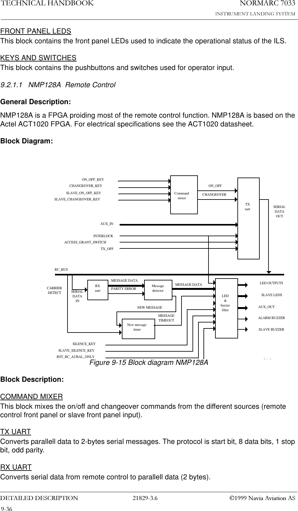
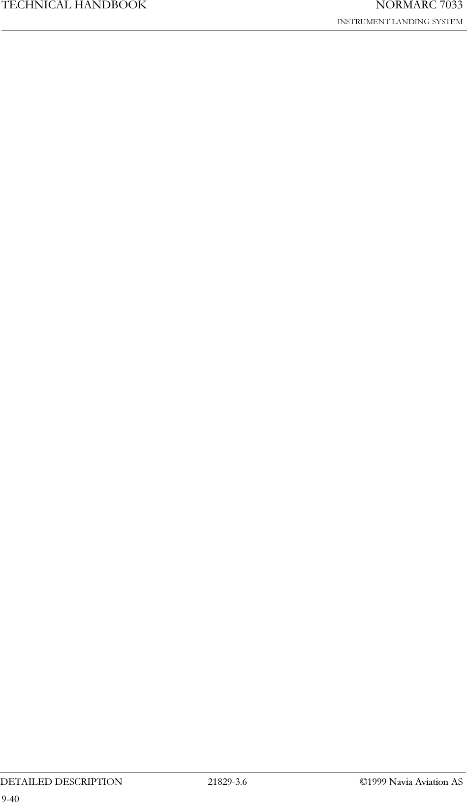
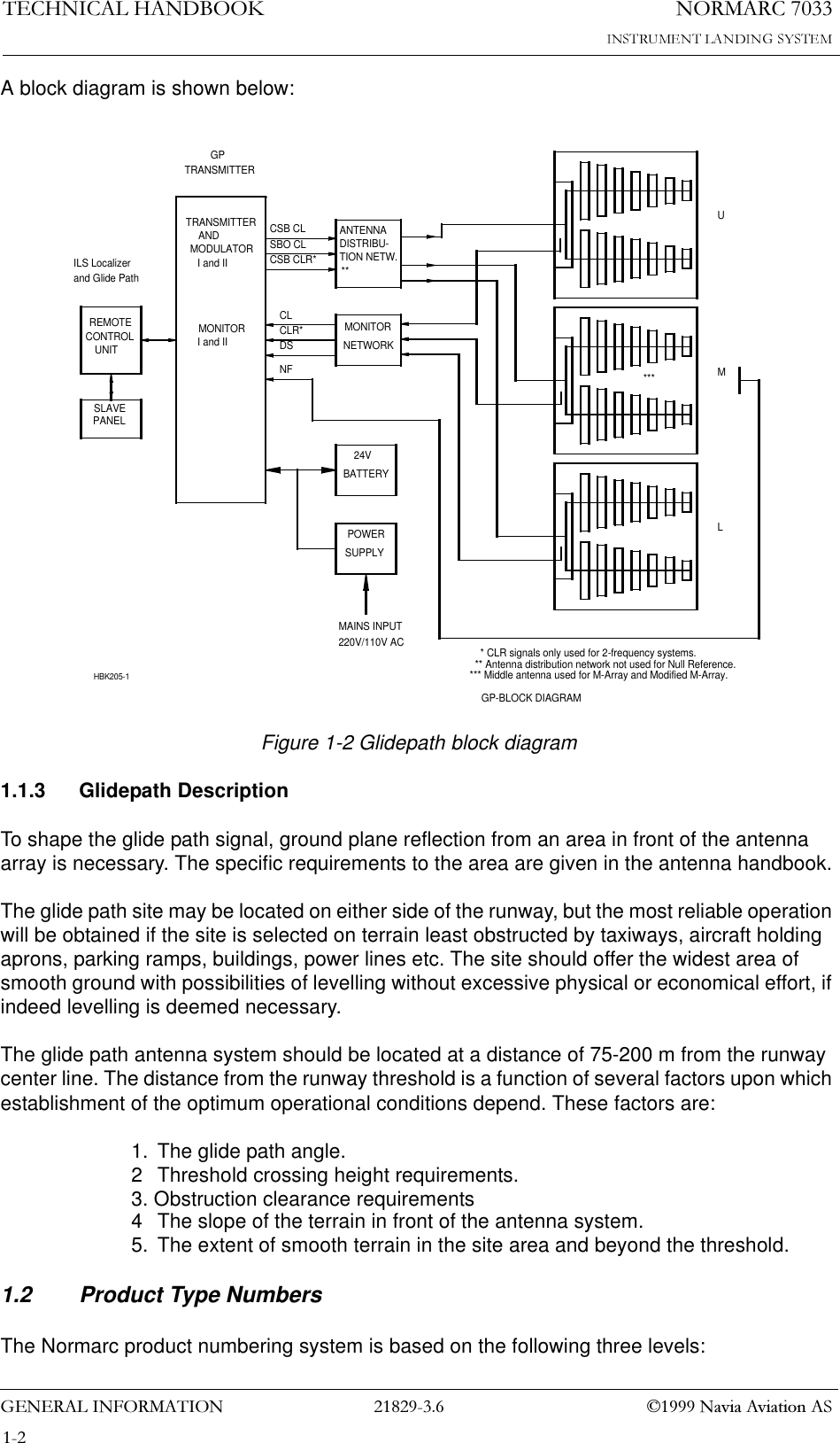
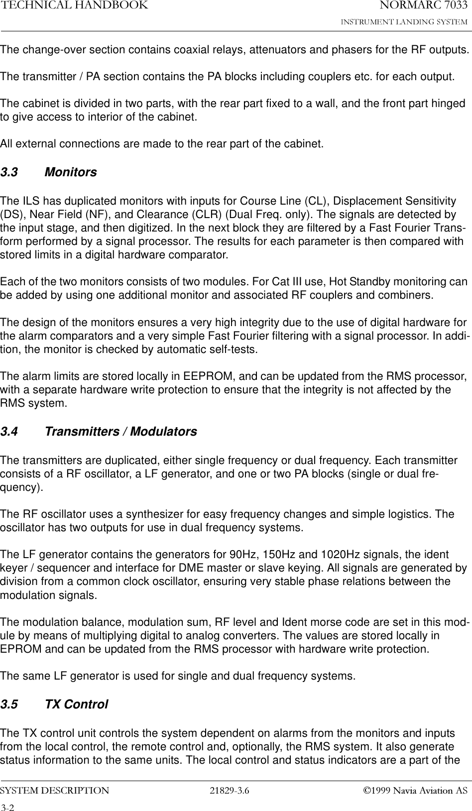
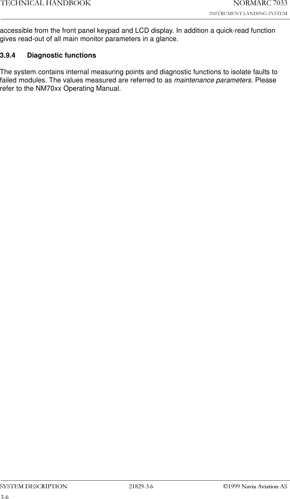
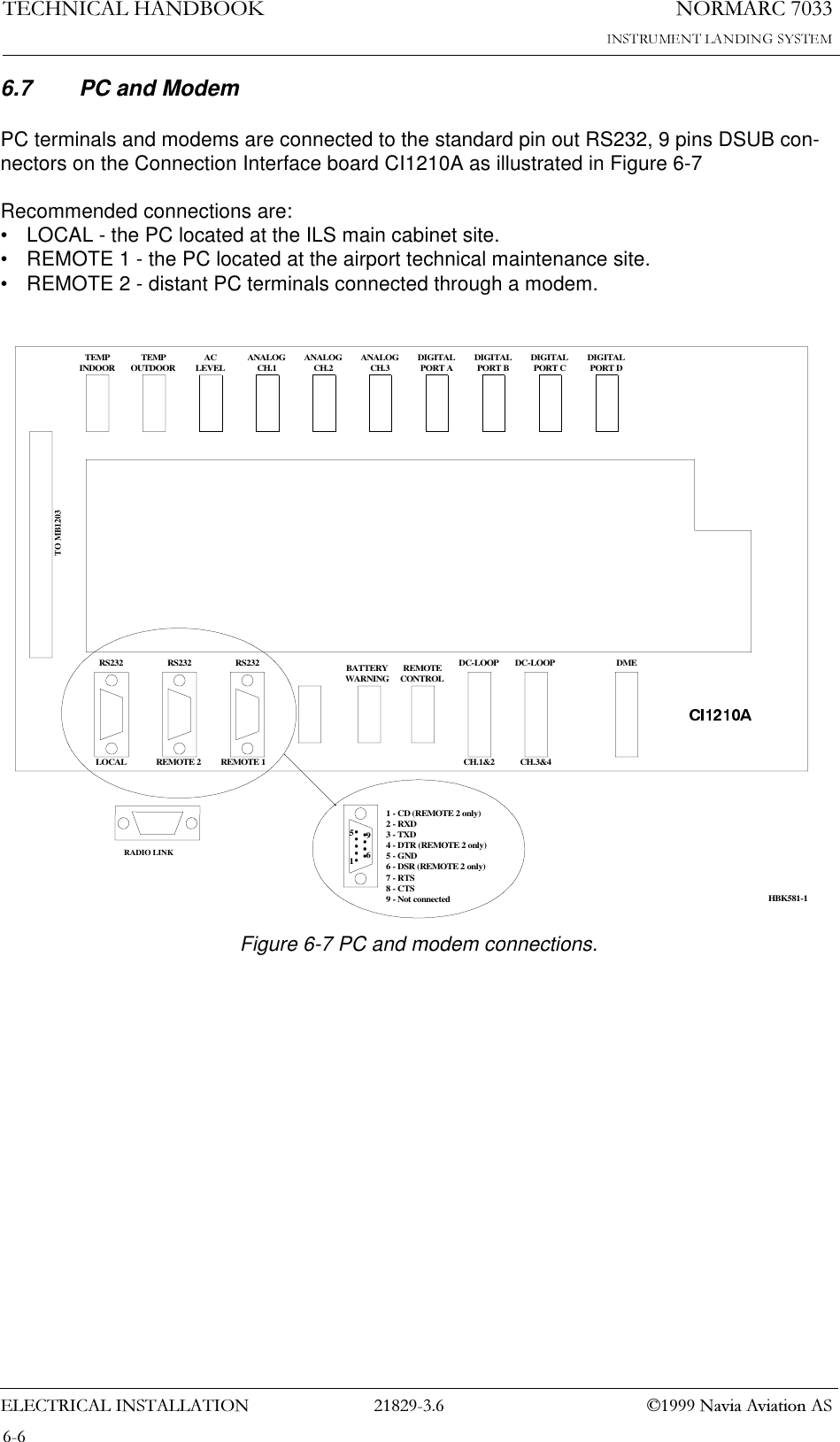
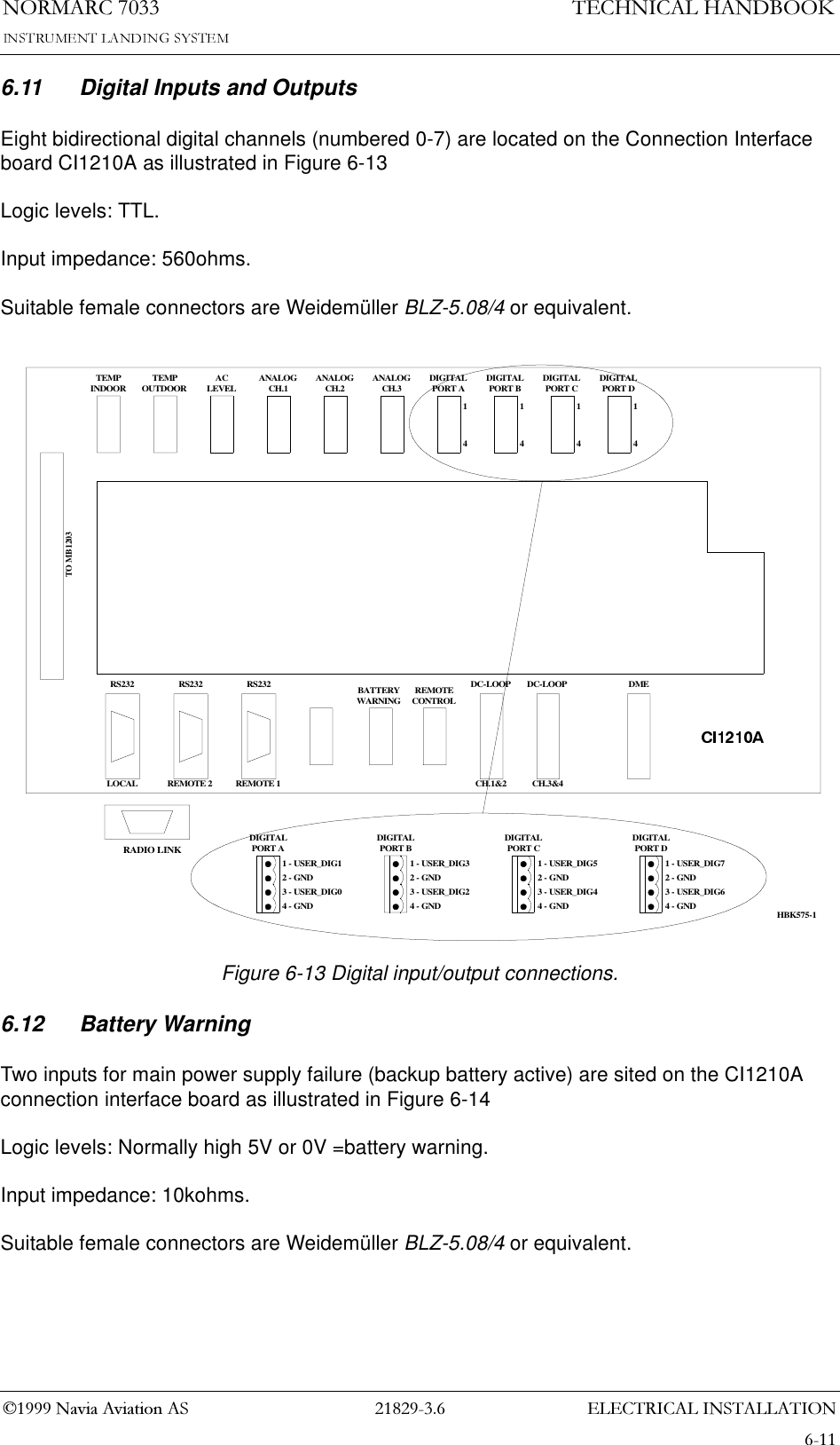
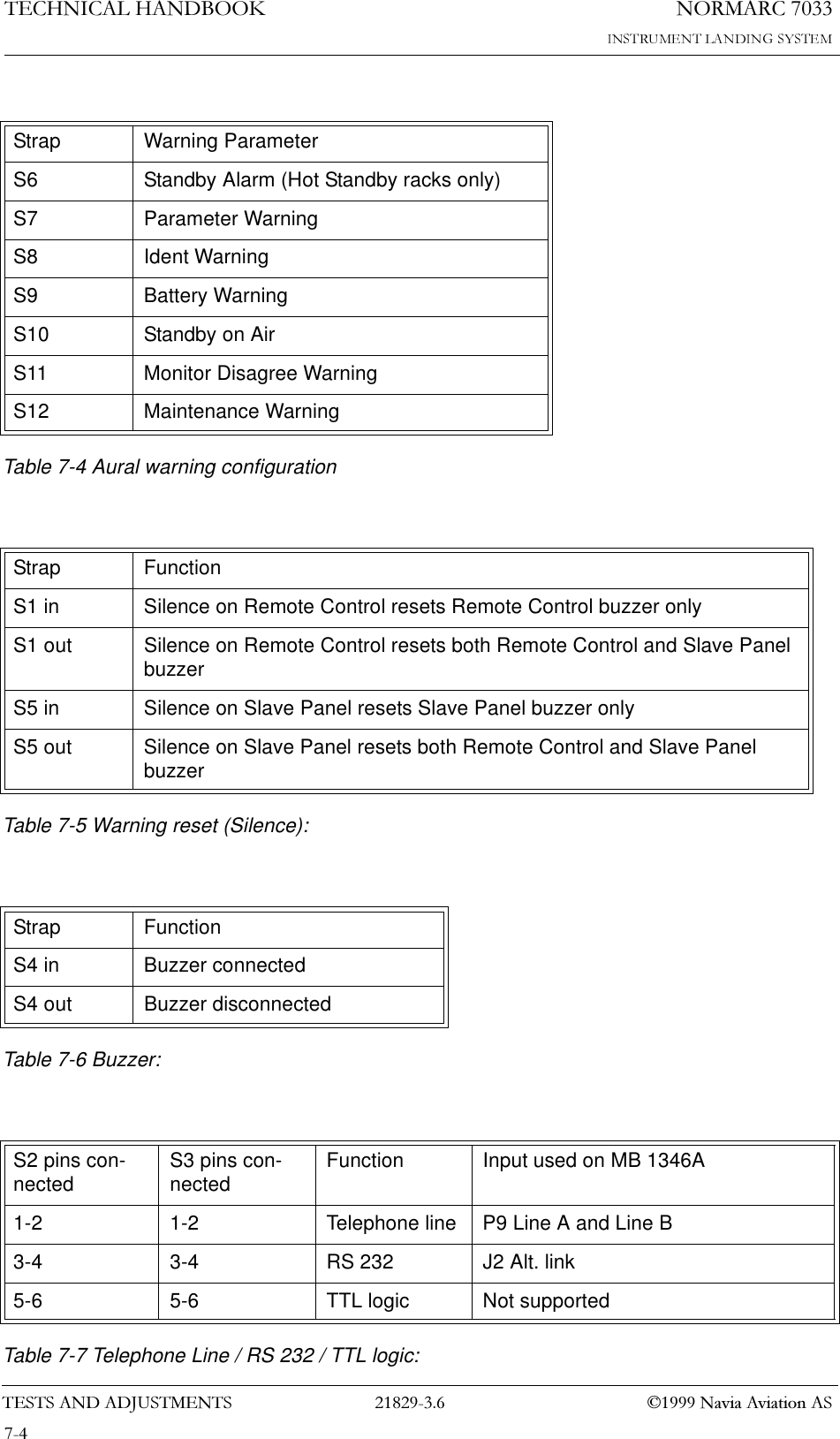
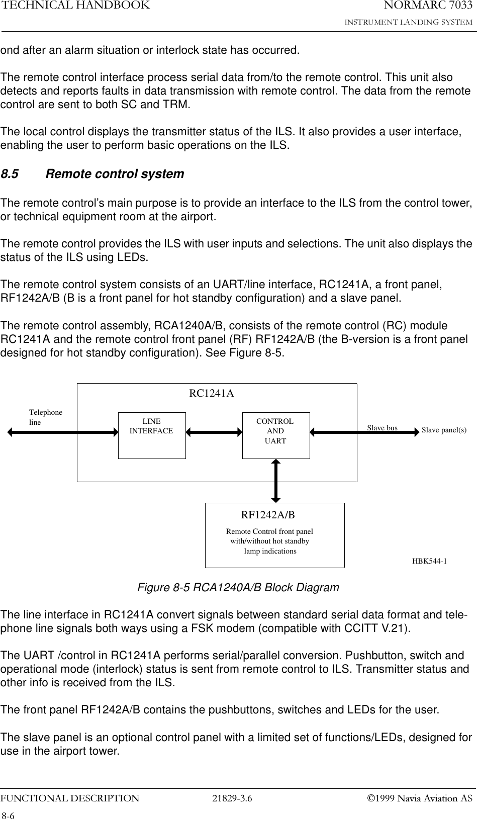
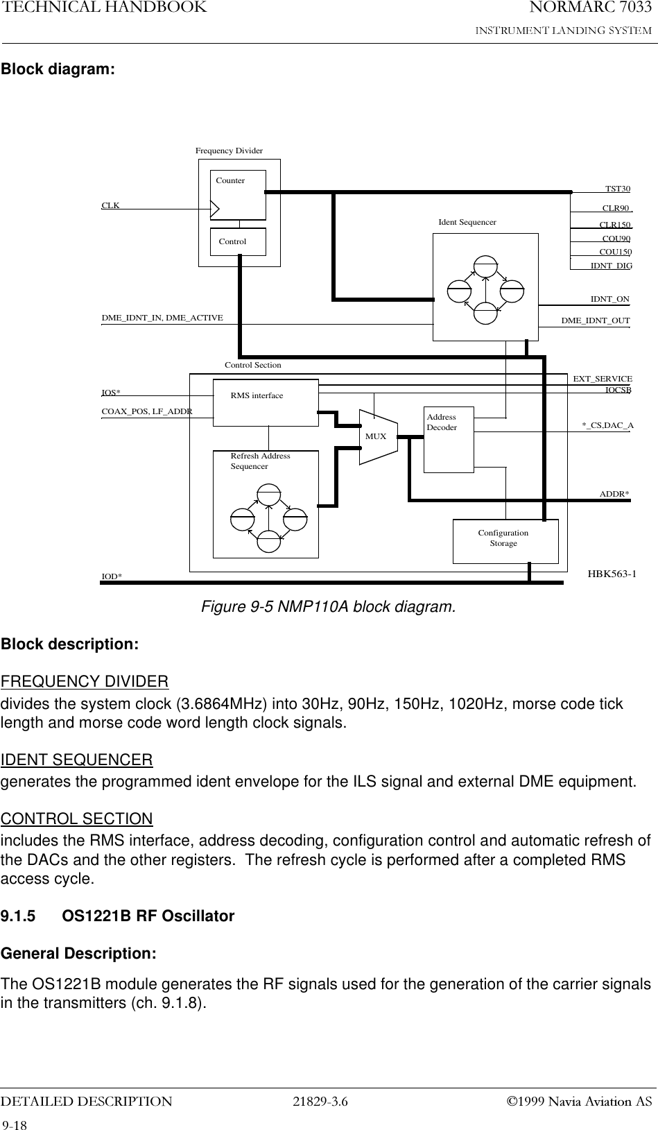
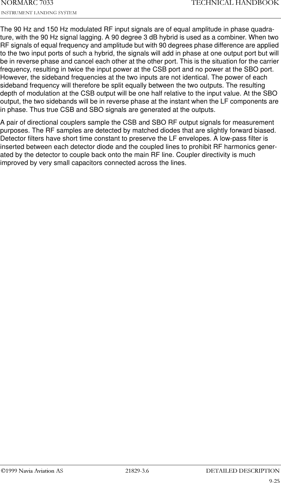
![1250$5&7(&+1,&$/+$1'%22.'(7$,/(''(6&5,37,21 1DYLD$YLDWLRQ$69.1.2 MO1212A MonitorGeneral Description:The MO1212A module digital converts and processes NAV parameters, compares them with programmable limits and reports alarm situations to the Station Control on TCA1218A (chap-ter 9.1.3) and the RMS.Block Diagram:See Figure 9-2.Block Description:LF_FRONT:The analog signals from MF1219A Monitor Frontend are multiplexed and digitized, and the difference frequency (DF) pulse train is counted as a 12 bits value. These digital values are multiplexed into the FIFO along with the DC loop (DL_Detect[3:0]), External (Ext_Val[11:0]) and test channels. The FIFO is seven words deep, and the sampling frequency is 640 Hz/channel. Much of the functionality of LF-Front is handled by a FPGA NMP101A which is described in chapter 9.1.2.1.DSP_FILTERperforms all filtering in the Monitor. Data is read from the LF_FRONTEND FIFO, AC data are FFT analyzed and for the DC data mean values are calculated. The calculated parameters are written to the COMPARATOR. DSP_FILTER consists of a TMS320C31 DSP, a memory block and a reset/watchdog circuit.COMPARATORcompares the parameters received from DSP_FILTER with the programmed upper and lower alarm limits. Alarm data are passed on to the Station Control and Terminator (on TCA1218A, chapter 9.1.3) on a dedicated bus. The COMPARATOR generates both instantanous and delayed alarms. The delayed signal is sent only if the alarm is still present after the pro-grammed delay period. All parameters, alarm and warning data are passed on to the RMS via an output FIFO (warning information is treated by the RMS). The alarm and warning limits and delays are stored in the local EEPROM. Much of the functionallity of COMPARATOR is han-dled by two FPGAs NMP102A and NMP103A described in chapter 9.1.2.2.9.1.2.1 NMP101A Monitor Digital FrontendGeneral description:NMP101A is a FPGA in the LF-FRONT block. It serves as an interface between the (digi-tized) inputs from the monitor frontend MF1219A and the DSP_FILTER block. NMP101A is based on the Actel ACT1020 FPGA. For electrical specifications see the ACT1020 datasheet.Block diagram:See Figure 9-2.Block description:REF COUNTERdivides the system clock (4.9152 MHz) for use in channel addressing. It also generates the read/convert puls to the external ADC.](https://usermanual.wiki/Leidos-Innovations/NORMARC7033.Normarc-7033-ILS-Technical-Handbook/User-Guide-90100-Page-82.png)
!['(7$,/(''(6&5,37,211250$5&7(&+1,&$/+$1'%22.1DYLD$YLDWLRQ$6Figure 9-2 MO1212A BlockdiagrammLF_FRONTANAFRONTCL_RFLEVELCL-BASEBANDCL_IDENTDS_*NF_*CLR_*DL_DETECT_*2234TEST_RF_ERRORTEST_RF_OKLPF CL_BB_DGR224TST_CH[1:0]MUXANA_CH[3:0]AD12ADO[11:0]DFNMP101REFCOUNTERDIFFFREQCOUNTERMUX FIFOCLK175551212EXT_VAL[11:0]LF_DREADFULLDO[16:0]DAVEXT_CH[2:0]EXT_ENA4RESETANDCHECKCIRCUITDIGITAL SIGNALPROCESSORADDRESSDECODERBOOTEPROM EXTERNALRAMDSP_FILTERSEQUENCECONTROLLERINPUTLATCHCOMPDELAYPARITYCHECKPARITYCHECK DELAYFIFOCONTROL FIFOWRRDRMSINTERF. EEPROMINTERF. EEPROMMONITORTER ALARMBUSNMP 102/103AMS_ALARM_RDYMS_ALARM_RAWMS_ALMS_AL_NMS_AL_ID[4:0]MT_AL_RDYMT_AL_NMT_ALMT_AL_ID[4:0]MT_AL_RDYIOD[7:0]IOS[6:0]RMS_LEVEL1PAR_WRDSP_DATA[11:0]DSP_DATA[16:12]124 4554COMPARATORFROMMF1211A4MUX17RMS BUSFROMTCA1218AMONITORSC ALARMBUS9TOTCA1218ATOTCA1218A4.9152 MHzVOLT.REF.VOLT.REF.DL_REF*HBK555-2SEQUENCECONTROLLER](https://usermanual.wiki/Leidos-Innovations/NORMARC7033.Normarc-7033-ILS-Technical-Handbook/User-Guide-90100-Page-85.png)
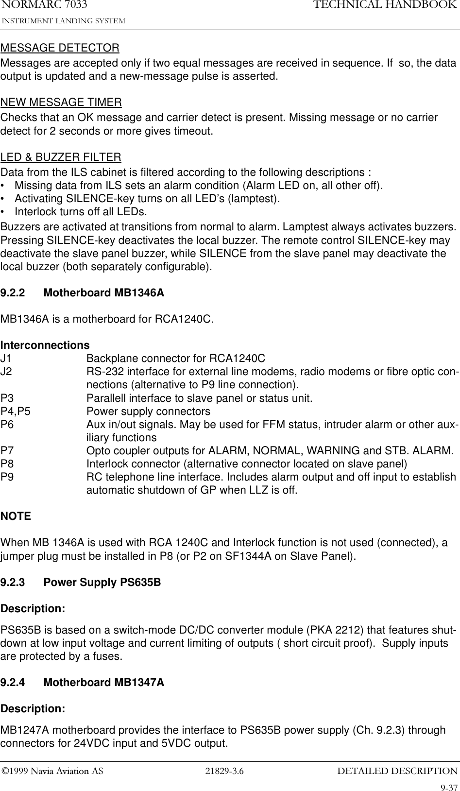
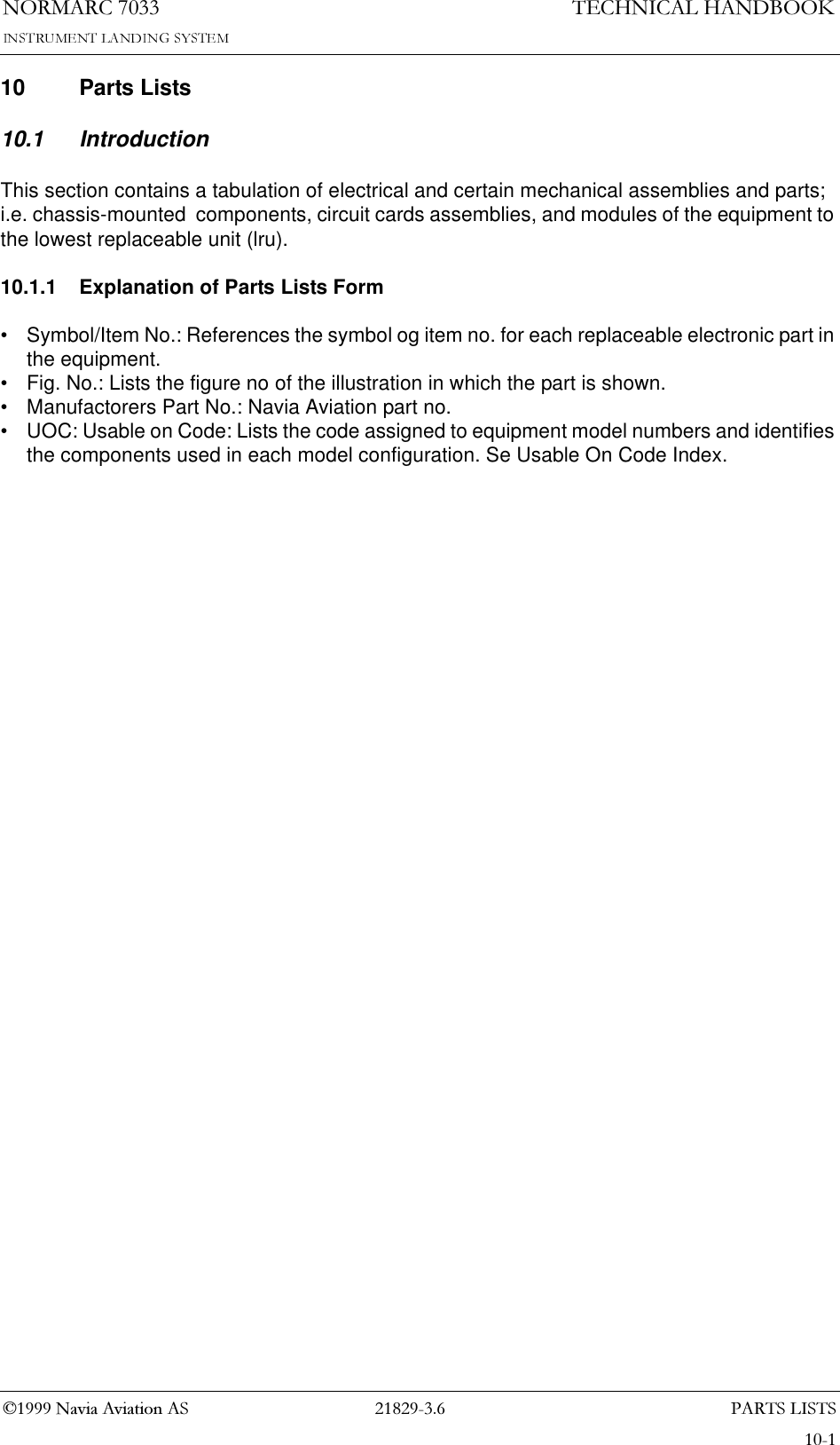
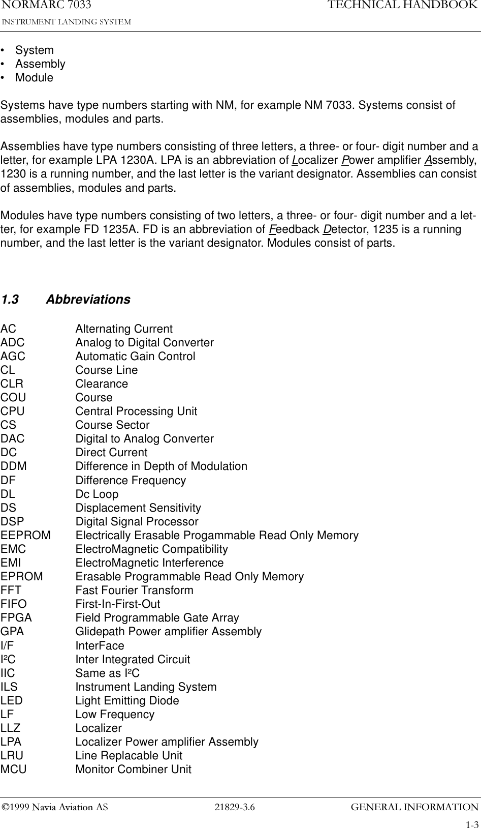
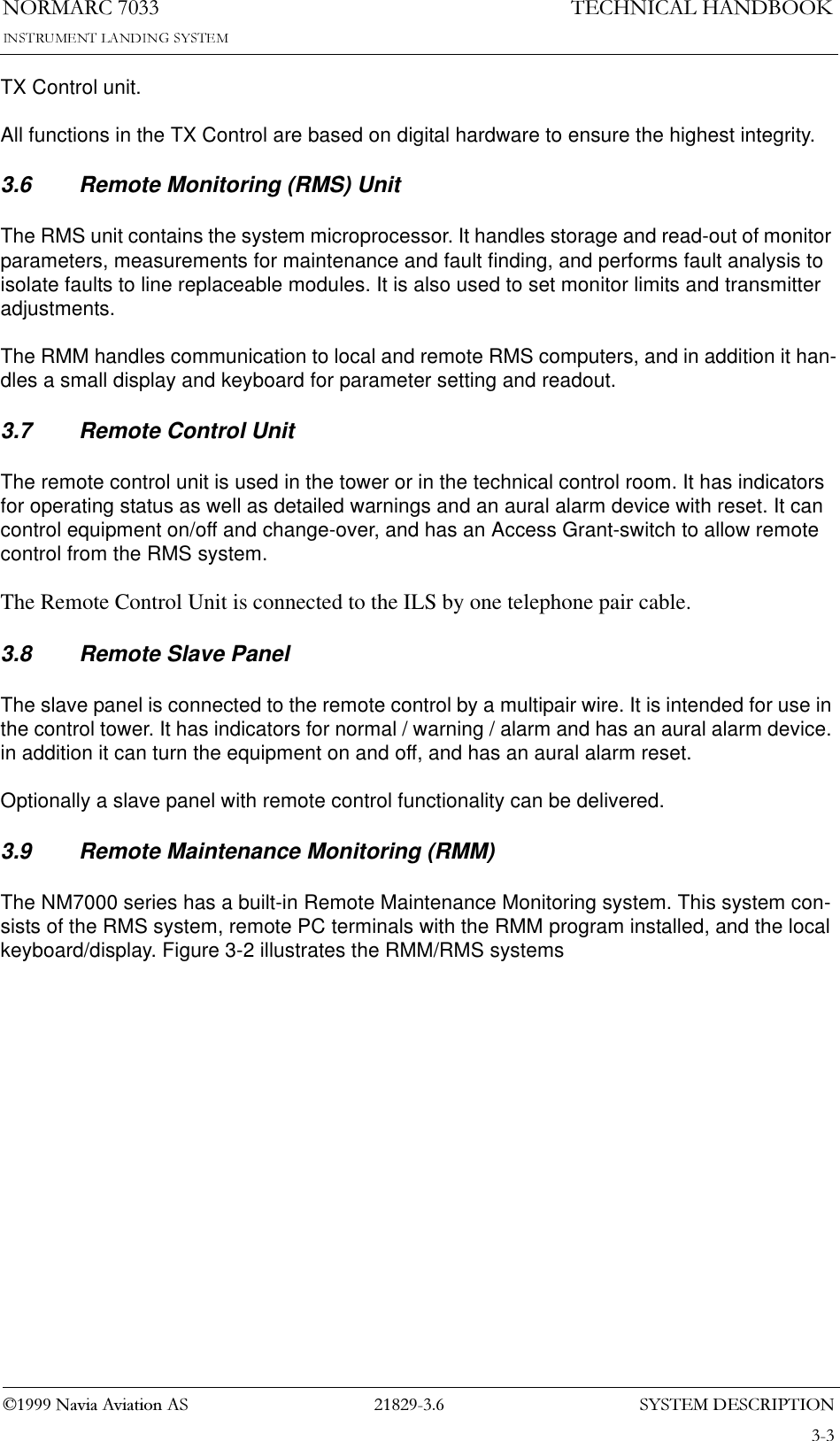
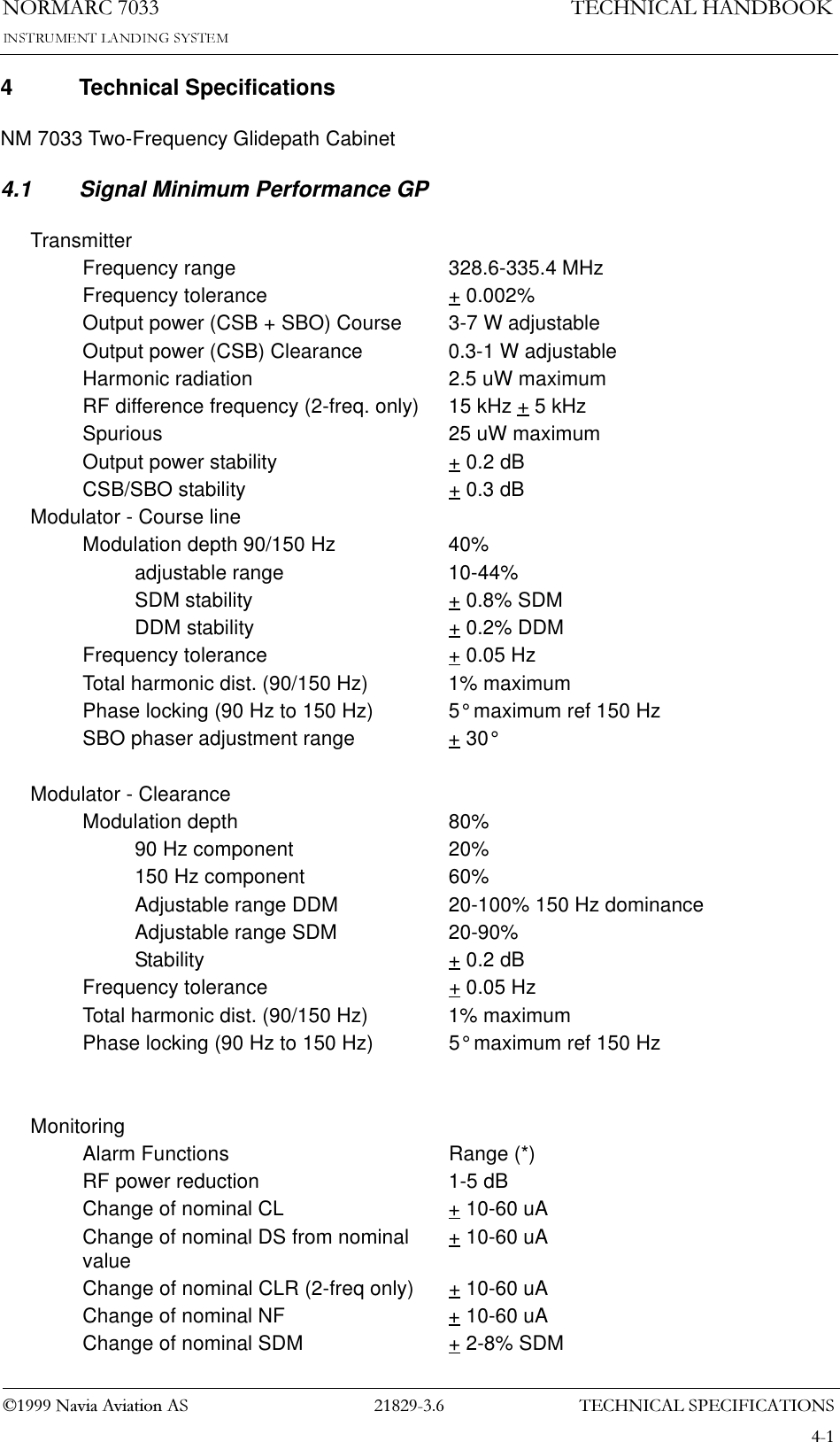
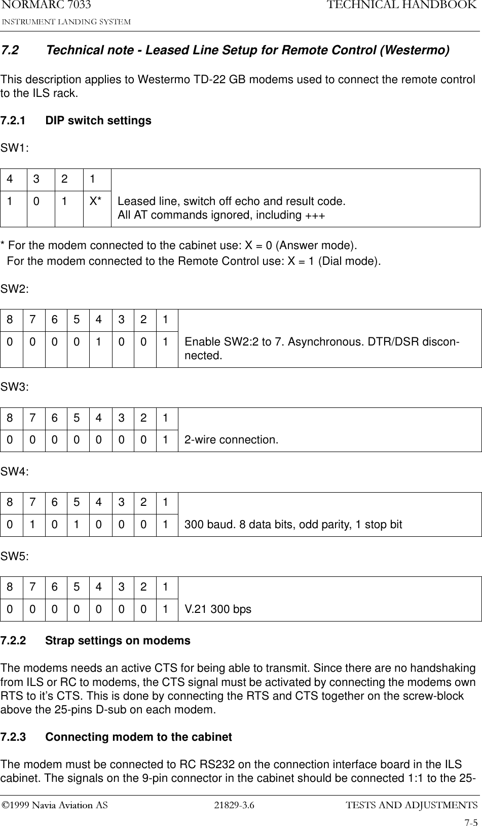
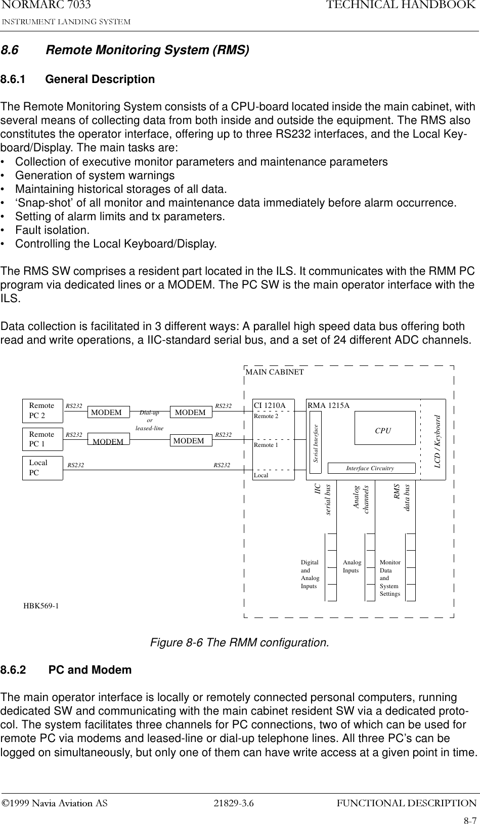
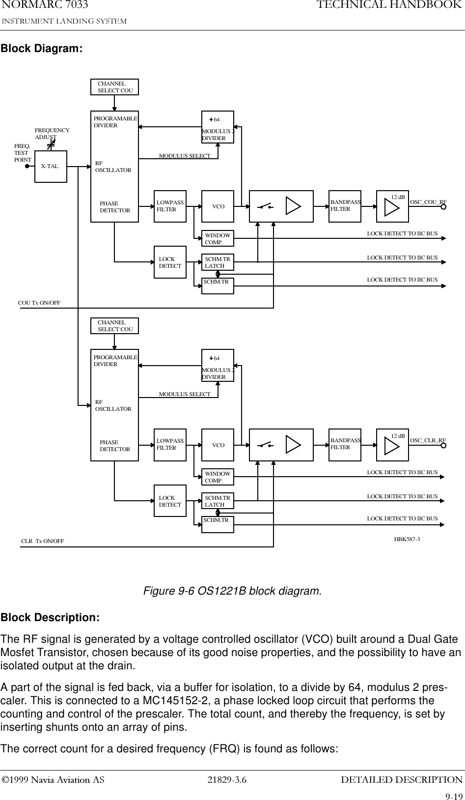
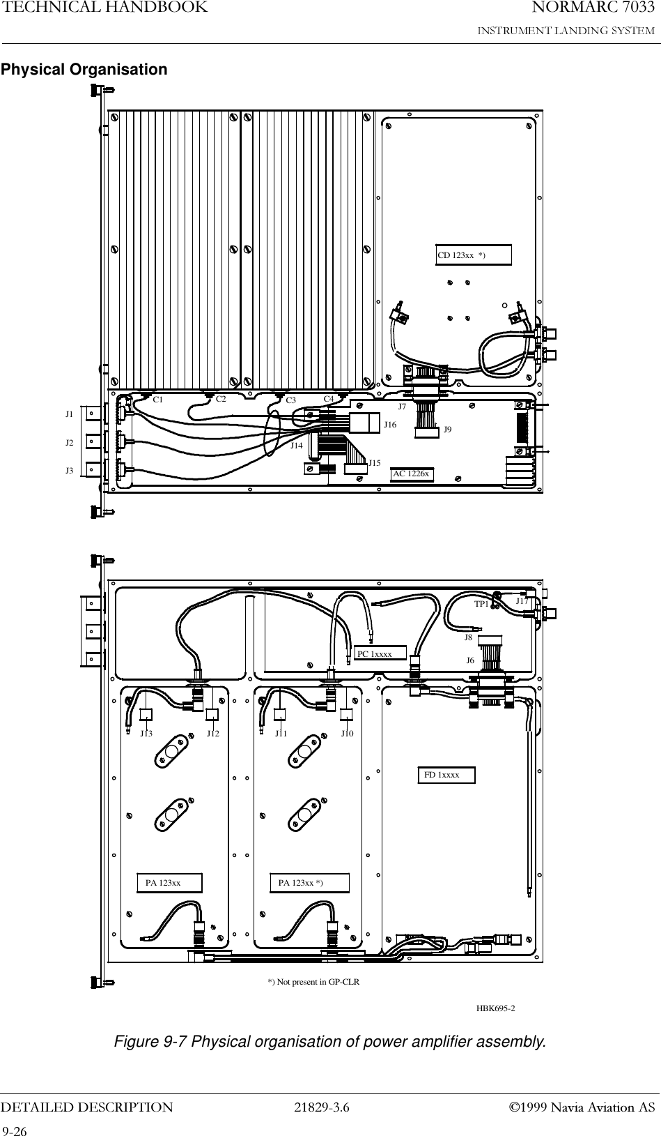
![1250$5&7(&+1,&$/+$1'%22.'(7$,/(''(6&5,37,21 1DYLD$YLDWLRQ$69.1.3 TCA1218A Transmitter Control AssemblyGeneral Description:The TCA1218A transmitter control assembly consists of the transmitter control TC1216A and Local Control (front panel) LC1217A.Block Diagram:See figure Figure 9-3 and Figure 9-4. All blocks except Local Control are located on TC1216A.Description of selected signals:MON1 SC ALARM BUS :Station control alarm bus from monitor MO1212A no.1. Consists of M1S_AL_ID[4:0], ~M1S_AL_RDY, M1S_AL, ~M1S_AL_N and M1S_AL_RAW.MON2 SC ALARM BUS :Station control alarm bus from monitor MO1212A no.2. Consists of M2S_AL_ID[4:0], ~M2S_AL_RDY, M2S_AL, ~M2S_AL_N and M2S_AL_RAW.STB MON ALARM BUS :Station control alarm bus from standby monitor MO1212A. Consists of ~MSTBS_AL_RDY and MSTBS_AL. Only used for hot standby configurations.RMS BUS :Interface to the RMS. Consists of IOD[7:0], IOCS, IOS[2:0].MON1 TRM ALARM BUS :Terminator alarm bus from monitor MO1212A no.1. Consists of M1T_AL_ID[4:0], ~M1T_AL_RDY, M1T_AL, ~M1T_AL_N and M1T_AL_RAW.MON2 TRM ALARM BUS :Terminator alarm bus from monitor 2. Consists of M2T_AL_ID[4:0], ~M2T_AL_RDY, M2T_AL, ~M2T_AL_N and M2T_AL_RAW.RC_BUS :Interface to the line interface circuits for the remote control interface on CI1210A (ch 9.1.11). Consists of SDIN, SDOUT, ~CD.Block Description:STATION CONTROLinterpret the alarm bus from the monitors MO1212A and generates alarm (and standby alarm for hot standby configurations). These signals together with inputs from local controls (on LC1217A), remote controls (via CI1210A), RMS inputs and configuration setup (in EEPROM and jumper settings) determine the state/state change for the NM70xx transmitter state. Sta-tus information are generated and sent to local control panel (LC1217A) and remote control panel (via CI1210A). The RMS can poll the state of the station control at any time. State changes generates an interrupt signal to the RMS. STATION CONTROL can shut off the transmitters GPA1231/1232A by turning off the RF-oscillators OS1221B.](https://usermanual.wiki/Leidos-Innovations/NORMARC7033.Normarc-7033-ILS-Technical-Handbook/User-Guide-90100-Page-86.png)
!['(7$,/(''(6&5,37,211250$5&7(&+1,&$/+$1'%22.1DYLD$YLDWLRQ$6Figure 9-3 TCA1218A Block diagram part 1VOTING_CONFIGM1S_AL_IDM1_ALM1S_AL_NM1S_AL_RAWM1S_AL_RDYMSTBS_AL_RDYMSTBS_ALMON1 ALARM& ERRORDETECTION VOTINGSTB ALARMDETECTIONPUSH-BUTTONONESHOTSLCIN[14:0]MON1 SC ALARM BUSMON2 SC ALARM BUSSTBMON SC ALARM BUSM1_ALARMM1_ERRORVALARMM2_ALARMM2_ERRORSTB_ALARMLC_INB[14:0]SC MON DATA DETECTORNMP104AFrom MO1212From MO1212From MO1212SW1THCES/PUSHBUTTONSLEDSWARN +STB LEDSLC_IN[10:0]LC1217ADEBOUNCELC_IN[14:11]CONFIGTRM CLOCKSEQUENCEREVENT CHECKTIMERDELAYEPROM READDATA ADDRESSPARITYCHECKLOCKUPDETECTTX ON/OFFCONTROLLOCAL LAMPSTATUSSEQUENCECONTROLEVENT NO USEDMAIN SELECT USEDEPROM READ DATATIMEOUTVALUETIMERTRIGTIMEOUT GONEEPROM READ DATASTATEMACHINEADDRESSCOAX POSEPROM ADDRPARITY ERRORDATA BYTESPENDINGEVENT NOLOCKTIMEOUTTXFBTXFBCOAXPOSSTATUS LAMPSMAIN SELECTSC STATE MACHINE CONTROLCONFIGURATIONSTO_BUSEPROM DATATXONLC_OUTCOAXPOSPENDINGST_BUSNMP106ARMSINTERFACERMSLEVEL DETECTEVENTDETECTINTERLOCKFILTERALARMAUTO-ONOFF-TXONOFFTERMI-NATORSTATE CHECKILOCK_INTALARM_INTMON1 ALARM& ERRORDETECTIONM1T_AL_IDM1T_AL_RDYM1T_ALM1T_AL_NM1T_AL_RAWVOTINGMON1TRMALARMBUSMON2TRMALARMBUSRMS_BUSCONFIGURATIONLC_INRI_BUS-TERM_ALTERM_INTTRM_RO_ALTRM_LC_ALNMP107ARMS LEVELRMS_STATUSRMS COMMANDSM1_ALARMM1_ERRORM2_ERRORM2_ALARMLC_IN[14:7,0]EPROMSC CLOCKSPSP~VALARM~LC_OUT[11:0]~LC_OUT[17:12]EPROMADDRESSMUXRCCONFIG123546789101112131415161718HBK 545A-2MON1 ALARM& ERRORDETECTIONM1T_AL_IDM1T_AL_RDYM1T_ALM1T_AL_NM1T_AL_RAWM2_ALM2S_AL_NM2S_AL_RAWM2S_AL_RDYMON1 ALARM& ERRORDETECTIONM2S_AL_ID](https://usermanual.wiki/Leidos-Innovations/NORMARC7033.Normarc-7033-ILS-Technical-Handbook/User-Guide-90100-Page-93.png)
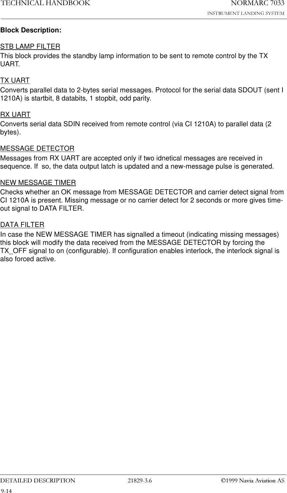
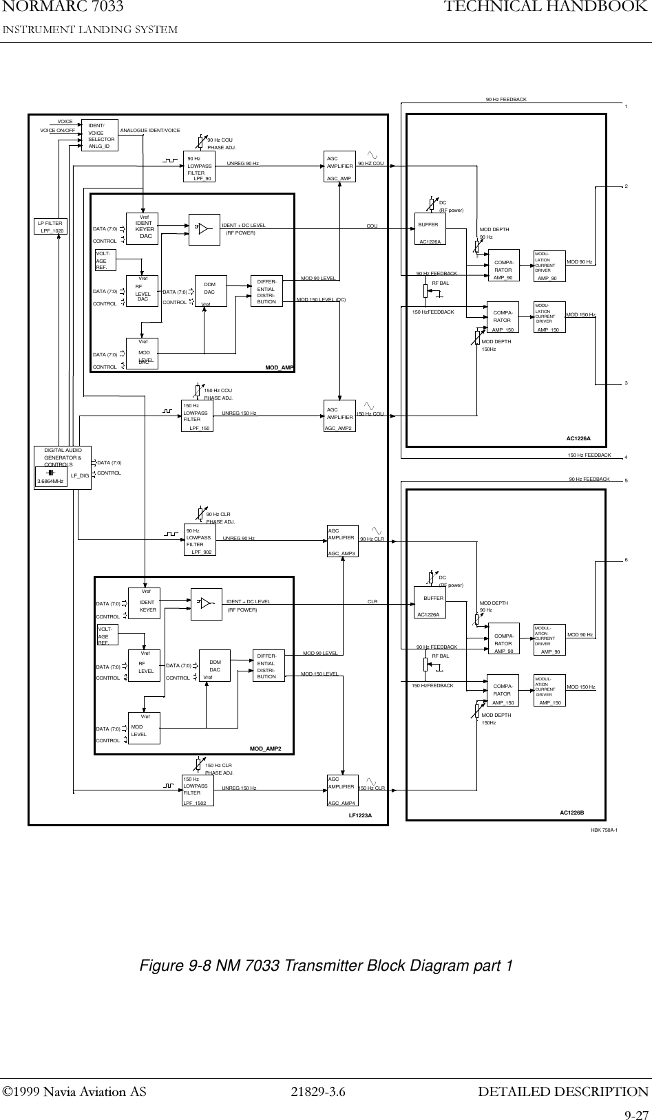
![1250$5&7(&+1,&$/+$1'%22.'(7$,/(''(6&5,37,21 1DYLD$YLDWLRQ$6Figure 9-4 TCA1218B Block diagram part 2LC_OUT[11:0]LCO_CONDREMOTE CONTROL INTERFACE (RI)STB LAMPFILTER TXUARTDATAFILTERMESSAGEDETECTORNEW MESSAGETIMERRXUARTRI_BUSAUX_OUTRO_BUSAUX_INCNF[6,4,1,0]SDINMESSAGETIMOUTSDOUTLC_OUT[17:12]NMP109ALC02CONDRMS INTERFACELAMP STATUSGENERATIONRMS LEVELDETECTEVENTDETECTINTERRUPTDETECTTX 20 SECDELAYMAIN SELECTSTOREINTERLOCKDELAYDLYACTIVE4STO_BUSRO_BUS (TX)RMS_LEVELFORCE_ALSC_INTVALARMSTALARM PENDINGRMS_BUSM1_A/EM2_A/ERI_BUSNMP105APS1227SPFrom MB1203(P15)From CI1210To CI1210To MB1203(P15)COAX_POS To coax relayTo OS1221~TXON[3:0] 4SPSPSPTo RM1213SP~CS~RMS_LEVEL[1:0]To MO1212 LF1223~TXC_INT2 SC EVENT DETECTIONCOAXFBTXFB[3:0]TRM_RO_ALARMSC_TXCOND123541718161514131211109876HBK545B-2](https://usermanual.wiki/Leidos-Innovations/NORMARC7033.Normarc-7033-ILS-Technical-Handbook/User-Guide-90100-Page-94.png)
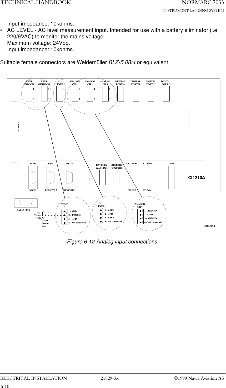
!['(7$,/(''(6&5,37,211250$5&7(&+1,&$/+$1'%22.1DYLD$YLDWLRQ$6• 1 AC-level measurement input• 3 Differential Analog inputs• 8 Auxilliary Digital Inputs/OutputsBlock Diagram:Figure 9-13 CI1210A Block diagram9.1.12 MB1203A Monitor Section MotherboardDescription:MB1203A is the backplane for the 19” subrack in the NM 70xx cabinet. MB 1203A is a passive motherboard that provides all interconnections between the printed circuit board in this sub-rack and all interface for external signals exept from RF (Coax) cabling.+-AAPSModemMUXTOUTDOORTINDOORVACP/NANLG3P/NANLG2P/NANLG1P/NEAMX*AIN*USER_DIG*FSK*SD*,CDVPOWVBATTV27PIIC*[RS232]DL_*[RS232]DL_*Over-VoltageProtection*DME*DME_*HBK532-1](https://usermanual.wiki/Leidos-Innovations/NORMARC7033.Normarc-7033-ILS-Technical-Handbook/User-Guide-90100-Page-111.png)