Leidos LPR902M-ICU-0 AVL GPS User Manual OEM Guide RIM 902M

Science Application International Corporation AVL GPS OEM Guide RIM 902M

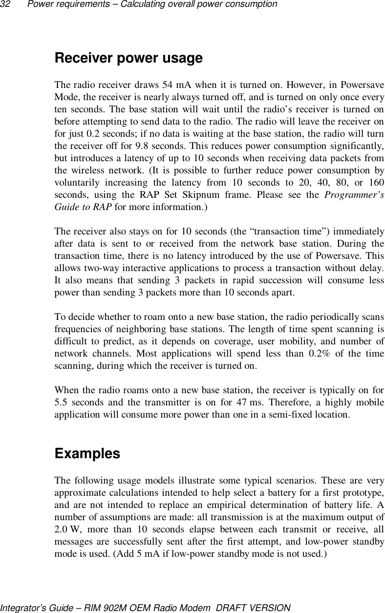
OEM Guide (RIM 902M)
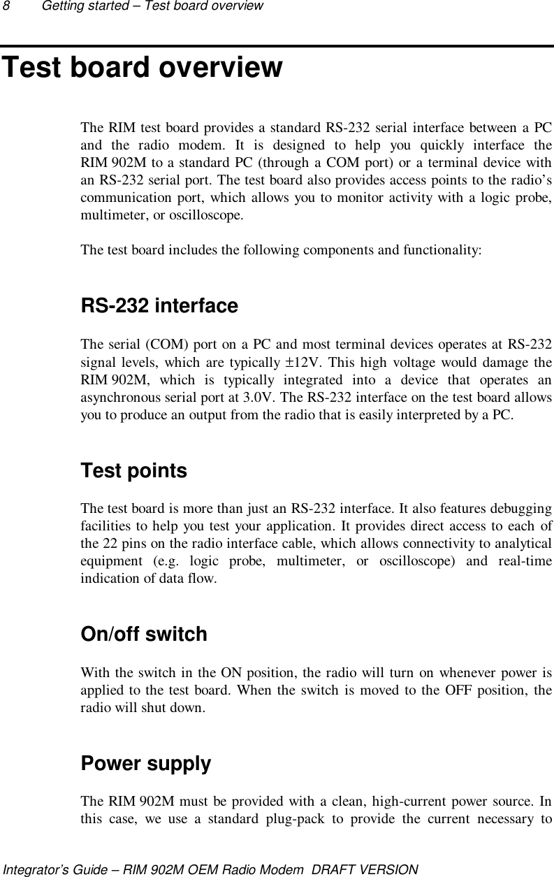
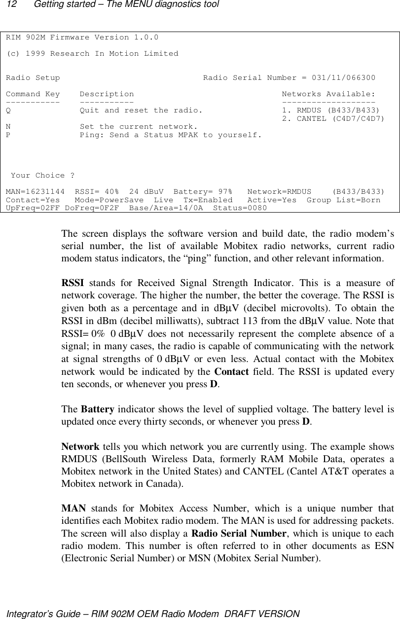
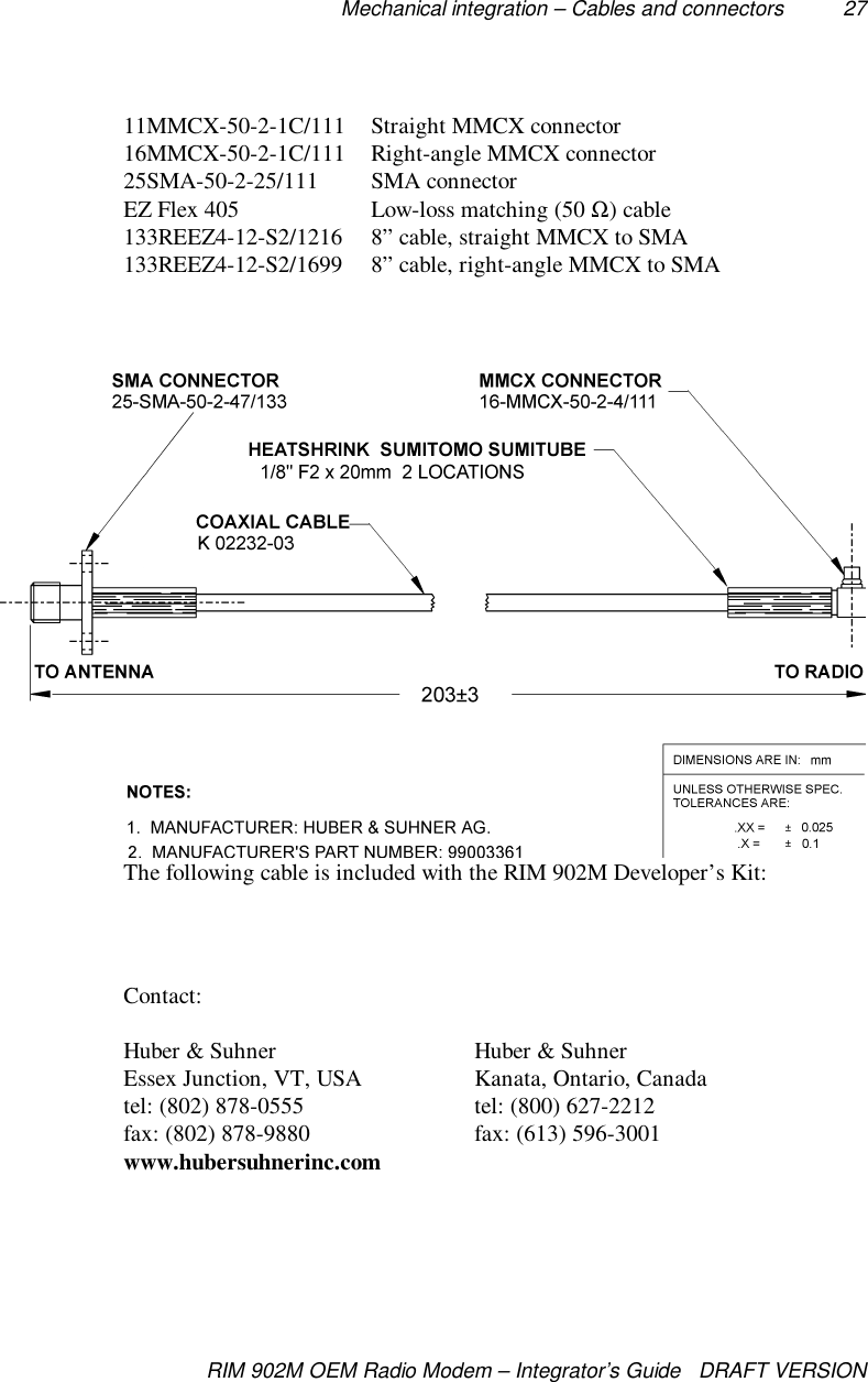
Integrator’sGuideRIM 902MOEM Radio Modem
RIM 902M OEM Radio Modem Integrator’s GuideLast Updated: October 21, 1999Model No. R902M-2-O© 1999, RESEARCH IN MOTION LIMITEDResearch In Motion and RIM are registered trademarks of Research In Motion Ltd.Mobitex is a trademark of the Swedish Telecommunications Administration.MS-DOS is a registered trademark, and Windows is a trademark, of Microsoft Corp.Warning: This document is for the use of licensed users only. Any unauthorisedcopying, distribution or disclosure of information is a violation of copyright laws.While every effort has been made to ensure technical accuracy, information in thisdocument is subject to change without notice and does not represent a commitment onthe part of Research In Motion Limited.Research In Motion295 Phillip StreetWaterloo, OntarioCanada N2L 3W8tel. (519) 888-7465fax (519) 888-7884Email: rim902m@rim.netWeb site: www.rim.netMOBITEX Interface, specifiedin SpecificationLZBA 703 1001,compatible equipment
FCC Compliance Statement (USA)FCC Class B Part 15This device complies with Part 15 of FCC Rules. Operation is subject tothe following two conditions:1.  This device may not cause harmful interference, and2.  This device must accept any interference received, includinginterference that may cause undesired operation.WarningChanges or modifications to this unit not expressly approved by theparty responsible for compliance could void the user’s authority tooperate this equipment.This equipment has been tested and found to comply with the limits for aClass B digital device, pursuant to Part 15 of the FCC Rules. Theselimits are designed to provide reasonable protection against harmfulinterference in a residential installation. This equipment generates, usesand can radiate radio frequency energy and, if not installed and used inaccordance with the manufacture’s instructions, may cause harmfulinterference to radio communications.There is no guarantee, however, that interference will not occur in aparticular installation. If this equipment does cause harmful interferenceto radio or television reception, which can be determined by turning theequipment off and on, the user is encouraged to try to correct theinterference by one or more of the following measures:•  Re-orient or relocate the receiving antenna.•  Increase the separation between the equipment and receiver.•  Connect the equipment into an outlet on a circuit different fromthat to which the receiver is connected.•  Consult the dealer or an experienced radio/TV technician forhelp.
Industry Canada CertificationThis device complies with Industry Canada RSS 119, under certificationnumber 2503195550A.IC Class B complianceThis device complies with the Class B limits for radio noise emissions as setout in the interference-causing equipment standard entitled “DigitalApparatus,” ICES-003 of Industry Canada.
ContentsFCC Compliance Statement (USA) ........................................iIndustry Canada Certification ...............................................iiAbout this guide.................................................................... v1. Introduction...............................................................1Radio performance...................................................................... 1Mobitex network technology....................................................... 42. Getting started........................................................... 7Test board overview.................................................................... 8How to connect the test board...................................................... 9The MENU diagnostics tool.......................................................103. Mechanical integration ........................................... 19Environmental properties...........................................................19Physical properties.....................................................................20Mounting methods.....................................................................20Cables and connectors................................................................254. Power requirements ................................................ 29Load specifications ....................................................................29Calculating overall power consumption......................................31Batteries ....................................................................................33Plug-in supplies .........................................................................34Automotive supplies...................................................................355. Interface specification ............................................. 37MASC and RAP link-layer protocols .........................................37Pin descriptions .........................................................................40How to turn the radio on and off ................................................45Loading firmware (optional) ......................................................466. Antenna selection .................................................... 49Selecting an antenna..................................................................49Introduction to antenna terminology..........................................51
Antenna design considerations...................................................53Shielding ...................................................................................55FCC radio frequency exposure rules...........................................56Specifications ...................................................................... 61Glossary of terms ................................................................ 63
About this guideThis guide will assist you in integrating the RIM 902M OEM radio modem intoa variety of devices such as laptop computers, handhelds, vending machines,point-of-sale terminals, vehicle-based mobile terminals, and alarm system.Topics covered in this guide include:• mounting requirements• power (battery) characteristics• interfacing to the RIM 902M• antenna selection and placementThroughout the guide, there are suggestions and precautions that will ease theimplementation of a wireless communication solution. You are encouraged tocontact RIM if you would like to discuss the technical implementation of thisradio modem.
 11. IntroductionWith the introduction of the RIM 902M, Research In Motion (RIM) has set anew standard for radio modem performance. The RIM 902M is unrivaled in thekey areas of receiver sensitivity, ouput efficiency, noise immunity, and powerconsumption. Its small size and weight make it suitable for virtually anywireless data application, including handheld devices and mobile terminals.The RIM 902M is designed for use with Mobitex wide-area wireless datanetworks operating in the 900 MHz range, such as the BellSouth IntelligentWireless Network and the Cantel AT&T Data Mobitex Network.RIM radio modems are specifically designed to integrate easily into acomputing device. Potential applications include:• Laptop computers • Vehicle tracking and location• Point of sale devices • Monitoring and telemetry• Ruggedized terminals • Vending machines• Handheld PC’s• Utility meters• Parking meters • Billboards• Dispatching • Security alarm panelsRadio performanceThe RIM 902M offers the highest performance of any radio modem forMobitex wireless data networks:
2 Introduction – Radio performanceIntegrator’s Guide – RIM 902M OEM Radio Modem  DRAFT VERSIONReceiver sensitivityReceiver sensitivity is a measure of how well a radio modem can “hear” anetwork base station. This figure is important when a device will be used inareas where signal strength is weak, such as inside buildings and in locationsthat are not close to a base station. A radio modem with good receiversensitivity can be used in more places than a radio modem with poor sensitivity.The RIM 902M has a receiver sensitivity of –116 dBm at 0.01 BER. Thismeans that the radio can interpret received data from a very weak signal(0.0025 picowatt) with a 1% bit error rate. 1% is an industry standard error rateused to define sensitivity, and does not indicate that 1% of the data passed bythe radio to the application is corrupted. The sophisticated over-the-air Mobitexprotocol corrects these errors before the data is passed to the application,ensuring error-free communication. This capability is already built into theradio’s firmware, and does not require any additional software development.Noise immunityThe RIM 902M is not de-sensitized by the electromagnetic interference (EMI)or  “noise” that is generated by the electronics of the terminal into which it isintegrated. As a result, no special shielding is required between the radio andyour device.Noise immunity offers several key benefits, including:• easier integration • improved RF performance• longer battery life • more coverage from each base station• increased reliability • no need for special RF shieldingPowerful and efficient transmitterWhen necessary, the RIM 902M can supply a full 2.0 watts to the antenna.However, the RIM 902M quickly decreases the output power when it is close toa base station − to as little as 0.06 watt – because a stronger signal is neededonly when far from a base station. By transmitting a strong signal only whennecessary, the RIM 902M conserves battery power and ensures a balanced link.The RIM 902M provides reliable transmit efficiency across the entire operatingvoltage range of 4.1 to 4.75 volts. As a result, batteries can be used even when
Introduction – Radio performance 3RIM 902M OEM Radio Modem – Integrator’s Guide   DRAFT VERSIONnearing depletion. This also maximizes the radio coverage area throughout thelife of the battery.Low power requirementsIf you are planning to integrate the RIM 902M into a handheld or portabledevice, battery life is a critical issue: your customers will insist on long lastingdevices without heavy battery packs. The RIM 902M sets a new powerconsumption standard for Mobitex radio modems. This ensures efficiency andmaximizes battery life.Transmitting data: 1.7 amps or less (at 4.5V), depending on output powerThe transmitter is ON for a pulse of between 32 ms and 1 second perpacket, depending on the amount of data transmitted. The maximumpacket size for a Mobitex device is 512 bytes.Receiving data: 54 mA (at 4.5V)The radio turns its receiver ON for a 150 ms “window” once every 10seconds. The base station will only attempt to communicate with the radioduring this window. To minimize latency during rapid two-waycommunication, the receiver is also turned ON and kept ON for 10seconds after any communication (transmit or receive) with the network.Standby power: less than 0.2 mA (at 4.5V)Standby power consumption is very low and occurs when no radio activityhas taken place for at least 10 seconds. The radio and base station areclosely synchronized to ensure that a communication attempt is not missedwhen the radio is in standby mode.Battery life is not a concern for certain applications, such as in-vehicleapplications that draw power from the vehicle battery. For these applications, itis possible to put the radio in an express operating mode, in which powerconsumption is higher than normal but packet transfer latency is reduced to aminimum.
4 Introduction – Mobitex network technologyIntegrator’s Guide – RIM 902M OEM Radio Modem  DRAFT VERSIONSmall sizeUsing a single board design, the RIM 902M is very thin, and much smallerthan a business card, at only 42.0 by 67.5 mm. This tiny size allows theRIM 902M to meet tight space requirements within most applications. Itssingle-board design is more reliable than multi-board designs, particularly inhigh-vibration environments (such as vehicles) or in devices that can bedropped (such as handheld PCs).Mobitex network technologyThe Mobitex wireless network technology, developed by Eritel in 1984 forSwedish Telecom, has become an international data communication standard.Now managed by the Mobitex Operators Association (MOA), which controlsthe specifications for this open standard, Mobitex is a secure, reliable, wirelesspacket switching network specifically designed for wide-area wireless datacommunications.Mobitex networks are deployed around the world. The technology is presentlyavailable in the following countries:• Australia • Germany • Singapore• Austria • Indonesia • Sweden• Belgium • Italy • Turkey• Canada • Korea • United Kingdom• Chile • Netherlands • United States• Finland • Norway • Venezuela• France • PolandMobitex networks in the United States, Canada, Korea, Chile, and Venezuelaoperate in the 900 MHz range, and are therefore directly compatible with theRIM 902M OEM radio modem. Currently, Mobitex networks in other countriesoperate at other frequencies, such as 400 MHz.Mobitex provides highly reliable, two-way digital data transmission. Thenetwork provides error detection and correction to ensure the integrity of thedata being sent and received, and includes transmission acknowledgment.The Mobitex network has a hierarchical structure that allows messages to berouted from sender to receiver along the most direct path possible. Each radio
Introduction – Mobitex network technology 5RIM 902M OEM Radio Modem – Integrator’s Guide   DRAFT VERSIONcell is served by an intelligent base station. Because intelligence is distributedthroughout the network, data is only forwarded to the lowest network nodecommon to the sender and the receiver. For example, one base station is able tohandle all traffic in its coverage area.The network constantly monitors the location of the mobile users. As a mobiledevice moves from one area of coverage to another, base stations track itssignals, sending updated mobile location and status information to the network.If the network goes down at any point in transmission, the message is held untilnetwork service is restored. If the mobile receiver moves outside the coveragearea, the base station stores the data until coverage is re-established, thenforwards it to the mobile. This prevents data loss, and increases the reliabilityof transmission.Mobitex is optimized for data communication. It uses a packet switchingtechnique to provide the greatest flexibility in data transmission. Conventionalcellular phone systems, by contrast, use a circuit-switched network, in which aphysical connection is created between the sending and receiving nodes, andmust be maintained throughout the duration of the transmission. With circuit-switched systems, the set-up time for establishing a connection involvessignificant overhead and airtime cost, especially when only a small amount ofdata needs to be transferred.Mobitex packets include information about the origin, destination, size, type,and sequence of data to be sent. This enables packets to be transmittedindividually, in any order, as traffic permits. Internal to the network, individualpackets may travel along different routes, in any order, without interfering withother packets sent over the same frequency by different users. At the receivingend, all packets are accounted for, and reassembled into the original message.Set up time is eliminated and network connection is instantaneous. As a result,packet-switching makes far more efficient use of channel capacity, typicallyallowing 10 to 50 times more users over a radio channel than a circuit switchednetwork.
22. Getting startedRIM is committed to facilitating the integration of the RIM 902M OEM radiomodem. We provide the necessary resources to evaluate the feasibility ofimplementing a wireless communication solution, and work closely with ourpartners to develop an application in the shortest time possible.Years of intense R&D have spawned several tools that have been usedinternally to help streamline our own development process. We have includedmany of these tools with the RIM 902M OEM Developer’s Kit. The purpose ofthe Kit is to accelerate radio integration and to help system designers evaluatethe RIM 902M. Using the Kit, you can quickly begin interfacing the radiomodem to your computing device.We’re here for you!RIM has a team of experienced engineers who can support you in the designand implementation of your project. If you need help getting started, or if youhave any questions about the radio technology or its integration into yourplatform, please contact the RIM 902M engineering development team:email: rim902m@rim.netphone: +1 (519) 888-7465fax: +1 (519) 888-7884web: www.rim.net
8 Getting started – Test board overviewIntegrator’s Guide – RIM 902M OEM Radio Modem  DRAFT VERSIONTest board overviewThe RIM test board provides a standard RS-232 serial interface between a PCand the radio modem. It is designed to help you quickly interface theRIM 902M to a standard PC (through a COM port) or a terminal device withan RS-232 serial port. The test board also provides access points to the radio’scommunication port, which allows you to monitor activity with a logic probe,multimeter, or oscilloscope.The test board includes the following components and functionality:RS-232 interfaceThe serial (COM) port on a PC and most terminal devices operates at RS-232signal levels, which are typically ±12V. This high voltage would damage theRIM 902M, which is typically integrated into a device that operates anasynchronous serial port at 3.0V. The RS-232 interface on the test board allowsyou to produce an output from the radio that is easily interpreted by a PC.Test pointsThe test board is more than just an RS-232 interface. It also features debuggingfacilities to help you test your application. It provides direct access to each ofthe 22 pins on the radio interface cable, which allows connectivity to analyticalequipment (e.g. logic probe, multimeter, or oscilloscope) and real-timeindication of data flow.On/off switchWith the switch in the ON position, the radio will turn on whenever power isapplied to the test board. When the switch is moved to the OFF position, theradio will shut down.Power supplyThe RIM 902M must be provided with a clean, high-current power source. Inthis case, we use a standard plug-pack to provide the current necessary to
Getting started – How to connect the test board 9RIM 902M OEM Radio Modem – Integrator’s Guide   DRAFT VERSIONoperate the radio. The voltage is converted into the necessary levels by thepower supply section on the test board.LED indicatorsThe test board includes several LED indicators designed to indicate the flow ofdata to and from the host (in real time), the radio power status, power to the testboard, and more.How to connect the test boardNow that you are familiar with the components and functions of the test board,you are ready to connect the RIM 902M radio modem to an antenna and to aPC (or some other computing device with an RS-232 serial interface). To dothis, you will use the test board and cables supplied with your RIM 902MDeveloper’s Kit.1. Flat interface cable (test board to radio)The flat interface cable carries data between the test board and the RIM 902M.Control and status signals such as TURNON are also carried on this cable. Usethis cable to connect the RIM 902M to the test board.This cable also carries clean, regulated power to the RIM 902M.When inserting the cable, ensure that the side with the bare pins are in directcontact with the pin side of the connector. To ensure proper contact, do notforce the cable into the connector. Instead, pull the tabs on either side of theconnector, slide the cable in, then push the tabs back in to tighten.2. DB-9 serial cable (test board to PC)Connect the male end of the straight-through DB-9 serial cable to the testboard.Connect the female end of the cable to your PC’s COM port.
10 Getting started – The MENU diagnostics toolIntegrator’s Guide – RIM 902M OEM Radio Modem  DRAFT VERSION3. Power adapter (test board to AC outlet)Plug the 5VDC, 2.4A, center-pin-positive power adapter into the wall outlet.Connect the other end to the power jack of the test board.4. Antenna cable (radio to magmount antenna)Your developer’s kit includes a high-performance, 6dB-gain magmountantenna. This antenna is terminated with a screw-on SMA plug. TheRIM 902M radio modem includes a snap-on MMCX jack. The antenna cablesupplied with your developer’s kit connects the antenna’s SMA plug to theradio’s MMCX jack.The magmount antenna provides optimum RF performance when placed on abroad metal surface, such as the roof of a car. When used inside a building,performance is improved if the antenna is located near a window, with fewobstacles (wall, furniture, equipment, etc.) between the antenna and thewindow. The antenna must be oriented vertically for best performance, andperforms equally well whether positioned rightside up or upside down.5. Turn the system onThe power switch on the test board is connected to the TURNON line of theRIM 902M radio modem. To determine whether the radio is on, look at theLED marked ONI. It is lit when the radio is on.The MENU diagnostics toolNow that you have successfully connected your RIM 902M radio modem toyour PC, you are ready to send a test packet through the Mobitex network.Your radio modem must be activated by the network operator in order to beused on the Mobitex network and to establish an airtime agreement. If you havenot already arranged for activation of your radio, contact your networkoperator.
Getting started – The MENU diagnostics tool 11RIM 902M OEM Radio Modem – Integrator’s Guide   DRAFT VERSIONThe RIM 902M contains a diagnostic utility called MENU. With this utility,you can set the current network, “ping” your radio modem, or view radio andnetwork status values.SetupThe following instructions assume that your RIM 902M is connected to a PCrunning a terminal program, such as Windows HyperTerminal. The MENUutility is based in the RIM 902M’s firmware, so HyperTerminal is the onlysoftware required to use it.The MENU utility’s user interface is a full-screen text mode interface, and usesthe ANSI cursor command set. Programs like HyperTerminal support the ANSIcodes by default. If you are using a different terminal program that does notprovide ANSI cursor control, the MENU utility will drop into a line-by-lineinterface. The appearance of the line-by-line interface is not documented here,but the commands it uses are the same as those described below.Select the COM port which communicates with the RIM 902M and configurefor 9600 bps, and either 7E1 (7 bits, Even parity, 1 stop bit) or 8N1 (8 bits, Noparity, 1 stop bit). If you have set this up correctly, you will see bursts ofcharacters from the radio modem such as ^0010B 47E,0:5D. These characterbursts are normal; they represent a MASC B frame, which you can ignore fornow.Type the word menu (all in lower case letters only) then press the ENTER key.You can expect to see a full screen of information. If nothing happens, simplyre-enter menu until the radio modem responds. The word “menu” itself willprobably not appear on the screen as you type it in.If you re-enter menu and nothing occurs, ensure that the radio is turned on andconnected to the PC, and that all cables are securely connected. Please contactRIM for assistance if you are stuck at this point.Once the utility has been started, the terminal program’s screen will looksimilar to the following:
12 Getting started – The MENU diagnostics toolIntegrator’s Guide – RIM 902M OEM Radio Modem  DRAFT VERSIONRIM 902M Firmware Version 1.0.0(c) 1999 Research In Motion LimitedRadio Setup                             Radio Serial Number = 031/11/066300Command Key    Description                              Networks Available:-----------    -----------                              -------------------Q              Quit and reset the radio.                1. RMDUS (B433/B433)                                                        2. CANTEL (C4D7/C4D7)N              Set the current network.P              Ping: Send a Status MPAK to yourself. Your Choice ?MAN=16231144  RSSI= 40%  24 dBuV  Battery= 97%   Network=RMDUS    (B433/B433)Contact=Yes   Mode=PowerSave  Live  Tx=Enabled   Active=Yes  Group List=BornUpFreq=02FF DoFreq=0F2F  Base/Area=14/0A  Status=0080The screen displays the software version and build date, the radio modem’sserial number, the list of available Mobitex radio networks, current radiomodem status indicators, the “ping” function, and other relevant information.RSSI stands for Received Signal Strength Indicator. This is a measure ofnetwork coverage. The higher the number, the better the coverage. The RSSI isgiven both as a percentage and in dBµV (decibel microvolts). To obtain theRSSI in dBm (decibel milliwatts), subtract 113 from the dBµV value. Note thatRSSI= 0%  0 dBµV does not necessarily represent the complete absence of asignal; in many cases, the radio is capable of communicating with the networkat signal strengths of 0 dBµV or even less. Actual contact with the Mobitexnetwork would be indicated by the Contact field. The RSSI is updated everyten seconds, or whenever you press D.The Battery indicator shows the level of supplied voltage. The battery level isupdated once every thirty seconds, or whenever you press D.Network tells you which network you are currently using. The example showsRMDUS (BellSouth Wireless Data, formerly RAM Mobile Data, operates aMobitex network in the United States) and CANTEL (Cantel AT&T operates aMobitex network in Canada).MAN stands for Mobitex Access Number, which is a unique number thatidentifies each Mobitex radio modem. The MAN is used for addressing packets.The screen will also display a Radio Serial Number, which is unique to eachradio modem. This number is often referred to in other documents as ESN(Electronic Serial Number) or MSN (Mobitex Serial Number).
Getting started – The MENU diagnostics tool 13RIM 902M OEM Radio Modem – Integrator’s Guide   DRAFT VERSIONMode shows whether the radio is in powersave mode or express mode. Thedefault operating mode is powersave, which reduces power consumption by theradio but introduces latency when receiving packets from the network. Thismode may be changed through software.Tx is an indicator to let you know whether the radio’s transmitter is enabled ordisabled. The transmitter may be enabled or disabled through software, and isnormally enabled. The Mobitex base station may also instruct a radio to shutdown (also referred to as DIE) if it is an illegal device, or not registered, orcausing disruption to the Mobitex network. If your device is in a DIE state,contact your network operator. The word Live on the status line indicates thatthe radio is not in a DIE state.A radio modem receives a Group List when it is powered up and registers withthe network base station. Normally, you would see Group List=OK, whichindicates that the radio has successfully signed onto a base station. If you seeGroup List=Born, then either your device is out of coverage, or it has not beenactivated by your network operator. Note that it can take 30 seconds for a radioto display Group List=OK.The Active state determines whether the radio is capable of receiving Mobitexdata packets. It does not mean the same thing as being activated with thenetwork. The radio may be inactive immediately on powerup.UpFreq and DoFreq show the channels (in hexadecimal) that you are using totransmit and receive, respectively. If you are interested in obtaining the exactcurrent transmit frequency, divide UpFreq by 80 and add to 890. This gives avalue in MHz. Add 39 MHz to obtain the receive channel. For example, if thedisplay reads “UpFreq=02FF DoFreq=0F2F” then convert hexadecimal 02FF todecimal 767, divide by 80 and add to 890, and obtain 899.5875 MHz, which isthe transmit channel. Add 39 MHz (or repeat the calculation using DoFreq) todetermine that the receive channel at 938.5875 MHz.Base/Area indicate which base station you are using. Every base station in thenetwork is assigned a unique Base/Area combination. Base stations in the samegeographic area often share an Area address. Contact your network operator ifyou want to know the location of network base stations.Status describes the current state of the radio. Other documentation may alsorefer to the Status value as the radio’s internal fault bits. The following tableshows the interpretation of the Status bits. If the Status value displayed on yourscreen does not correspond to any of the values below, then determine whichvalues add together in hexadecimal to give the Status value that you see. For
14 Getting started – The MENU diagnostics toolIntegrator’s Guide – RIM 902M OEM Radio Modem  DRAFT VERSIONexample, status value B403 would simultaneously describe states A000, 1000,0400, 0001, and 0002, as described below.Please note: if status bits are set, it does not necessarily indicate that there is afault with the radio. These bits are useful only for troubleshooting a knownproblem, and should not be read or interpreted by any application. For example,it is possible for the status bits to read 0040 yet the radio is able to transmit.0000 The radio modem status is normal. There are no warnings.0001 The RIM 902M has been out of coverage for a long time. No adequate basestation was found. Possible causes include lack of network coverage, wrongnetwork selected, or the battery level is too low.0002 This is a new RIM 902M being used for the first time. No action is necessary.0008 The radio modem has exhausted its internal memory. This should not happenunder ordinary use. Turning off the radio modem then turning it back on willresolve this.0020 The network has issued a DIE command to the radio modem, perhaps becauseit is not registered on the network. No data can be sent to the network until aLIVE command is issued by the network. Contact the network operator forhelp.0040 The modem’s transmitter has been disabled by your software, using either theMASC “F M0” or RAP “Turn Transmitter Off” command. The transmitter canbe turned back on with the MASC “F M1” or RAP “Turn Transmitter On”command, or by resetting the radio.0080 The radio modem has not yet received a grouplist from the network. If this bitremains set after the modem has been in network coverage for several minutes,your radio modem is probably not activated. Contact the network operator toactivate your device.0100 Another device may be using the same MAN number as your device on thesame base station. This should not happen under ordinary use. It may causeduplicate, dropped, or mixed up packets. Contact the network operator todetermine whether two units have the same MAN number.0800 The RIM 902M may be having a problem remembering its last base station. Ifthe problem persists, the unit should be returned for repair.1000 The RIM 902M has received an unknown interrupt and might be havingproblems receiving packets. If the problem persists, the unit should be returnedfor repair.2000 The RIM 902M has received an unknown interrupt. No action is necessary.4000 The RIM 902M has been damaged and cannot be used until this problem iscorrected. The unit should be returned for repair.
Getting started – The MENU diagnostics tool 15RIM 902M OEM Radio Modem – Integrator’s Guide   DRAFT VERSIONHow to change to a different networkThe RIM 902M radio may be used on different Mobitex networks operating ondifferent channels in the 900 MHz range. Up to 16 network channel lists maybe programmed by RIM into each radio. If the network shown is not the correctone, you can choose another from the list of networks available. Press N andthe MENU utility will present an additional prompt for selecting the network,as shown below.RIM 902M Firmware Version 1.0.0 release(c) 1999 Research In Motion LimitedRadio Setup                             Radio Serial Number = 031/11/066300Command Key    Description                              Networks Available:-----------    -----------                              -------------------Q              Quit and reset the radio.                1. RMDUS (B433/B433)                                                        2. CANTEL (C4D7/C4D7)N              Set the current network.P              Ping: Send a Status MPAK to yourself. Your Choice ? Choose a network from the list (1..2) ?MAN=16231144  RSSI= 30%  22 dBuV  Battery= 97%   Network=RMDUS    (B433/B433)Contact=Yes   Mode=PowerSave  Live  Tx=Enabled   Active=Yes  Group List=BornUpFreq=02FF DoFreq=0F2F  Base/Area=14/0A  Status=0080Change network nameYou may now enter a number corresponding to the desired network shownunder Networks Available. When you press ENTER, the radio modem willswitch to the selected network, as shown below. If you do not enter a number,or if you erase the number you have typed, then no change will occur when youpress ENTER. Pressing ESC will cancel the network set-up command.The screen below shows what would happen if you press 2 then ENTER. Thevalues shown beside Network, UpFreq, DoFreq, and Base/Area have changed.
16 Getting started – The MENU diagnostics toolIntegrator’s Guide – RIM 902M OEM Radio Modem  DRAFT VERSIONRIM 902M Firmware Version 1.0.0(c) 1999 Research In Motion LimitedRadio Setup                             Radio Serial Number = 031/11/066300Command Key    Description                              Networks Available:-----------    -----------                              -------------------Q              Quit and reset the radio.                1. RMDUS (B433/B433)                                                        2. CANTEL (C4D7/C4D7)N              Set the current network.P              Ping: Send a Status MPAK to yourself. Your Choice ?MAN=16231144  RSSI= 45%  25 dBuV  Battery= 97%   Network=CANTEL   (C4D7/C4D7)Contact=Yes   Mode=Fallback   Live  Tx=Enabled   Active=No   Group List=BornUpFreq=030D DoFreq=0F3D  Base/Area=1B/09  Status=0080Radio update was successful.“Ping” the network: an end-to-end radio testYou can determine whether your radio modem is working on the network bypressing  P. When you “ping,” you send a message (MPAK – Mobitex datapacket) to yourself via the wireless network base station. The MENU utility willdisplay a message indicating that the MPAK was sent. A few seconds later, itshould also indicate that the MPAK was received. This confirms that your radiomodem is operational and active on the network.If you get the message “Status MPAK cannot be sent – out of coverage”, thenyou are not in an area that is covered by the Mobitex network. You candetermine whether you are in coverage by looking at Contact on the statuslines. If you are certain that you are in a coverage area, but are still not able tocommunicate with the network, check the antenna to make sure it is connectedproperly and is positioned vertically. Signal quality can vary significantlywithin a building. Try moving the antenna to a new location, perhaps near awindow,  to see if you can get a signal.If you get the message indicating that the Status MPAK was sent, but you didnot get one that it was received, then you are in coverage but your RIM 902Mradio modem has probably not been activated by your network operator, and thenetwork will not send the MPAK back to the radio. Contact the networkoperator to activate your device.
Getting started – The MENU diagnostics tool 17RIM 902M OEM Radio Modem – Integrator’s Guide   DRAFT VERSIONRIM 902M Firmware Version 1.0.0(c) 1999 Research In Motion LimitedRadio Setup                             Radio Serial Number = 031/11/066383Command Key    Description                              Networks Available:-----------    -----------                              -------------------Q              Quit and reset the radio.                1. RMDUS (B433/B433)                                                        2. CANTEL (C4D7/C4D7)N              Set the current network.P              Ping: Send a Status MPAK to yourself. Your Choice ?MAN=16231227  RSSI= 11%  14 dBuV  Battery=100%   Network=RMDUS    (B433/B433)Contact=Yes   Mode=PowerSave  Live  Tx=Enabled   Active=Yes  Group List=BornUpFreq=02FF DoFreq=0F2F  Base/Area=14/0A  Status=0080Received MPAK from 16231227 (to 16231227) Type=03(STATUS  )  Traffic/Flags=00If you are unable to communicate with the network, first contact the networkoperator to make sure that your device is activated on the network. If the radiohas not been activated, then the network will not send the MPAK back to theradio. Second, make sure that you are in network coverage. You can determinewhether you are in coverage by looking at Contact on the status lines. If itshows Contact=NO, then you are not in an area that is covered by your Mobitexnetwork. You can also determine whether the antenna is connected properlyand is deployed properly. Signal quality in buildings can vary significantly overshort distances. Try moving the antenna to a new location, perhaps near awindow,  to see if you can get a signal. If none of these remedies help, contactRIM for assistance.Exiting the utilityWhen you have finished using the utility, you should press Q to quit. This stepis important because it allows the radio to resume accepting commands fromother software. The screen will clear and you will be informed that the radiohas been reset. You can safely disconnect the radio and close your terminalprogram once you have seen this message.
33. MechanicalintegrationThis chapter provides information about the RIM 902M that will be useful indetermining the physical positioning of the radio modem within an application.Environmental properties and testing, physical properties, mounting methods,and connector information are provided.Environmental propertiesDuring environmental testing, RIM takes samples of its radio modems andsubjects them to a variety of harsh conditions. We measure over a hundreddigital RF calibration parameters, once before and once after each test. Thedifference between these measurements precisely reveals any performancedegradation. Each unit in the sample is also inspected visually after testing.This experience allows us to fine-tune our design and manufacturing process.Environmental testing ensures that our products are able to withstand bothtypical and extreme real-world conditions in which they will be used. RIM doesnot sell units that have been subject to environmental testing.
20 Mechanical integration – Physical propertiesIntegrator’s Guide – RIM 902M OEM Radio Modem  DRAFT VERSIONStorage temperatureThe RIM 902M OEM radio modem may be stored at a temperature from -40°Cto +85°C (-40°F to +185°F).Operating temperatureThe RIM 902M is designed to operate between -30°C to +70°C (-22°F to+158°F). The end user should be careful not to exceed the upper temperaturelimit, as performance degradation or damage to the power amplifier may occurpast this point, especially while transmitting.The radio contains a temperature sensor that will automatically shut off thetransmitter if the temperature reaches approximately +75°C (+167°F).Physical propertiesWeightThe RIM 902M weighs 35 g (1.2 oz), including the case.DimensionsThe RIM 902M has been designed to meet the most stringent spacerequirements. In most cases, there will be sufficient room in an existingenclosure to house the radio modem.The overall maximum dimensions of the radio modem, not including cables,are:• Width: 42.0 mm (1.65”)• Length: 67.5 mm (2.66”)• Thickness: 8.4 mm (0.33”)
Mechanical integration – Physical properties 21RIM 902M OEM Radio Modem – Integrator’s Guide   DRAFT VERSION
22 Mechanical integration – Mounting methodsIntegrator’s Guide – RIM 902M OEM Radio Modem  DRAFT VERSIONMounting methodsThe RIM 902M OEM radio modem may be securely fastened using a variety ofmethods. The operating environment must be carefully considered whenchoosing a mounting option. For example, extreme temperature, heavyvibration, or high electromagnetic interference areas may require a specialmounting solution. It is important to ensure that the RIM 902M remainssecurely attached in the environment where it will be used.The following information is presented as a guide, but applications can varyconsiderably. A mechanical engineer can help ensure that the mounting methodis suitable for the specific application.Bolts or standoffsThe RIM 902M radio modem includes a hole in each corner, which may beused to bolt the device onto a circuit board, device housing, stand-offs, or othersurface. The mounting hole pattern is four holes in a 62.5 by 36.5 mmrectangle, with each hole 2.5 mm in diameter.To allow room for components on your board underneath the radio, you mayuse standoffs instead of bolts. This is illustrated in the following diagram.
Mechanical integration – Mounting methods 23RIM 902M OEM Radio Modem – Integrator’s Guide   DRAFT VERSIONTie wrapsTie wraps can be used as a secure but non-permanent means of attaching theRIM 902M to a surface. Typically, each tie wrap passes through a hole drilled
24 Mechanical integration – Mounting methodsIntegrator’s Guide – RIM 902M OEM Radio Modem  DRAFT VERSIONinto the surface of your board, on either side of the RIM 902M. This allows theradio to be attached to a shell, a PCB, or some other mounting surface.If using tie wraps, ensure that the surface beneath the RIM 902M is flat.Otherwise, the mounting surface could push up on the bottom surface of theradio case while tightening the tie wraps pushes down on the edge of the radiocase. This could cause the metal case of the RIM 902M to flex upward andshort across components inside the radio, causing the radio to malfunction. Forexample, thick adhesive foam tape and tie wraps should not be used together.Permanent industrial adhesiveThe RIM 902M is small and lightweight enough to be attached to the hostdevice using an industrial adhesive. For some applications, this method ofmounting is preferable to bolts, because adhesive is easier to use in amanufacturing environment, and is more resistant than bolts to loosening. Inmany cases, an effective solution is to adhere the radio modem to the insidesurface of your product’s casing.An adhesive should be chosen on the basis of its ability to stick to the materialused in the outer casing of the radio modem and in the surface to which theradio will be mounted. The bottom casing of the RIM 902M is magnesium.3M manufactures VHB, a permanent industrial adhesive with excellent long-term holding power. The peel adhesion and tensile holding power of VHB tapesare extremely high, making this a suitable solution when the radio will notneed to be removed. Choose foam tape for rough surfaces and adhesive tape forsmooth surfaces.More information about VHB may be obtained by contacting 3M IndustrialTape and Specialties Division at 1-800-227-5085 (fax: 1-612-733-1771). Thepublication number for the VHB technical data sheet is 70-0702-0266-1(104.5)R1.
Mechanical integration – Cables and connectors 25RIM 902M OEM Radio Modem – Integrator’s Guide   DRAFT VERSIONCables and connectorsThere are two connectors on the RIM 902M radio modem. One connector isused to interface the radio modem to a serial computing device and a powersupply, and a second connector is used to connect an antenna to the radio.Interface cable and connectorSerial communication data, control signals, and power are carried on a flat 22-conductor 0.30 mm (0.012”) thick flexible printed circuit (FPC) cable with1.00 mm centerline spacing, which can plug into a matching connector. Sinceeach application is unique, Molex can create a custom Flat Flex Cable Jumperin the correct length and the correct connector orientation for your application.The minimum cable length available is 30 mm (1.181”).The interface cable supplied with the RIM 902M Developer’s Kit is a Type D76.2 mm  (3.0”) long Flat Flex Cable (FFC) Jumper in 1.00 mm centerlinespacing, Molex part number 8800-8071, as illustrated in the followingmechanical drawing:
26 Mechanical integration – Cables and connectorsIntegrator’s Guide – RIM 902M OEM Radio Modem  DRAFT VERSIONThis cable can plug into a matching 22-position 1.0 [0.039] horizontal FPCconnector. A variety of connectors are manufactured by Molex. Moreinformation about each connector, including mechanical drawings, is availablefrom the manufacturer’s web site (www.molex.com), or you can contact RIM(rim902m@rim.net) for help with selecting an appropriate connector for yourapplication.Contact:Molex Headquarters Molex Electronics Ltd.Lisle, IL, USA Toronto, Ontario, Canadatel: (630) 969-4550 tel: (416) 292-1444fax: (630) 969-1352 fax: (416) 292-2922www.molex.comAntenna cable and connectorsRIM uses the industry-standard MMCX connector for the RIM 902M because itis a very small connector that has the mating force to withstand heavyvibration.Typically, an antenna does not plug directly into a RIM 902M. Instead, a cableis used between the radio’s antenna connector and a second connector at theouter casing of the device. This allows the antenna to be removed from thesystem without having to open the device, and it eliminates a source of strainon the radio’s MMCX connector.The antenna cable should have low loss, an impedance of 50 Ω, and an MMCXjack that mates with the RIM 902M’s MMCX plug. The other end of the cablecan be any connector you choose, as long as it has an impedance of 50 Ω. AnSMA screw-on connector is suitable and widely available. TNC connectors arealso suitable, but larger than SMA. The antenna cable supplied with theRIM 902M developer’s kit has an MMCX connector on one end and an SMAconnector on the other. The cable is built with strain reliefs to prevent damage.Huber & Suhner can provide antenna cables and connectors. The partsdescribed below have an impedance of 50 Ω and are suitable for use with theRIM 902M.
Mechanical integration – Cables and connectors 27RIM 902M OEM Radio Modem – Integrator’s Guide   DRAFT VERSION11MMCX-50-2-1C/111 Straight MMCX connector16MMCX-50-2-1C/111 Right-angle MMCX connector25SMA-50-2-25/111 SMA connectorEZ Flex 405 Low-loss matching (50 Ω) cable133REEZ4-12-S2/1216 8” cable, straight MMCX to SMA133REEZ4-12-S2/1699 8” cable, right-angle MMCX to SMAThe following cable is included with the RIM 902M Developer’s Kit:Contact:Huber & Suhner Huber & SuhnerEssex Junction, VT, USA Kanata, Ontario, Canadatel: (802) 878-0555 tel: (800) 627-2212fax: (802) 878-9880 fax: (613) 596-3001www.hubersuhnerinc.com
 44. Power requirementsThe RIM 902M radio modem must be provided with a clean power sourcecapable of delivering bursts of high current. This can be provided by a plug-inpower supply unit, a rechargeable battery pack, or single-use batteries. RIM hasconducted extensive research to develop guidelines for integrators who followdesign the power supply system for the RIM 902M.Load specificationsThe RIM 902M draws its power in bursts; the power required changes rapidlydepending on whether the radio is transmitting, receiving, or in standby. Theload profile is given on the following page. These specifications can be givendirectly to your power supply designer or battery supplier.Power supply parametersThe RIM 902M requires a clean, stable 4.1 to 4.75 volt source that is capable ofdelivering a one-second burst of up to 1.7 A when required by the transmitter.Maximum efficiency is obtained at 4.1V. RIM recommends designing a morerobust power supply that can provide adequate power under such non-idealconditions as an improperly matched antenna, under which this burst could beas high as 2.2A. The receiver current consumption is 54 mA. The standbycurrent consumption is less than 0.2 mA in “deep sleep” mode and 5.5 mA inregular standby mode.
30 Power requirements – Load specificationsIntegrator’s Guide – RIM 902M OEM Radio Modem  DRAFT VERSIONRadio load profile (at 4.5V)Transmitter− transmitting 2.0 W to antenna…− worst-case peak instantaneous (due to extreme   temperature, poorly matched antenna, etc.)…1.7 A2.2 AReceiver 54 mARegular Standby 5.5 mALow-power Standby < 0.2 mATransmit duration– minimum…− maximum…32 ms960 msOff current consumption ≤  20 µAOverall power consumption (assume heavy usage)− based on 0.05% transmit, 5.00% receive, and   94.95% low-power standby…− if low-power standby is not used…3.7 mA8.8 mARipple specificationFor best performance, ripple of less than 15 mV peak-to-peak (measured at theradio end of the connector) is recommended across the frequency range 60 Hzand 1 MHz. The maximum ripple at the connector that can be tolerated is20 mV peak-to-peak.Except in special cases where there are several sources of ripple, this meansthat you measure the ripple with an oscilloscope set to 1 MHz bandwidth, andthe peak-to-peak value is not to exceed 15 mV. Note that if there are severalripple components, or if ripple is measured with a larger (typically 20 MHz)bandwidth, ripple will seem worse. If it is still below 15 mV under theseconditions, it will meet the ripple specification.A passive LC (series L, shunt C) power filter can be put between your powersupply and the RIM 902M radio modem to reduce ripple at the radio connector.Bear in mind that the RIM 902M radio already has about 70 µF of on-boardshunt capacitance. The inductor cannot exceed 100 µH (otherwise, transientscould reset the radio), it must be rated to pass the maximum DC current of
Power requirements – Calculating overall power consumption 31RIM 902M OEM Radio Modem – Integrator’s Guide   DRAFT VERSION2.2 A supply current at all temperatures, and its resistance must be low enoughto guarantee minimum voltage of 4.1 V to the RIM 902M at 2.2 A.Calculating overall power consumptionThe instantaneous power consumption varies between 0.2 mA and 1.7 A, arange of four orders of magnitude. At any given point in time, the powerconsumption depends on what the radio is doing. Calculating the overall powerconsumption is important if a battery with appropriate capacity is to be properlyselected.The current figures below are all measured at a supply voltage of 4.5 V. Theactual operating range of the supply voltage is 4.1 to 4.75 V.Transmitter power usageThe radio transmitter draws 1.7 A to transmit 2.0 W, which is the maximumoutput power possible. The radio will automatically reduce the output power tothe minimum required to be heard by the base station; this reduces the currentrequirement. The minimum output power is 60 mW and typically occurs whenthe radio is very close to a base station. The maximum duration of a transmitpulse is 960 ms (required to transmit 512 bytes of user data) and the minimumis 32 ms (required to transmit 1 byte of user data, or to acknowledge a receiveddata packet). The actual transmitter ON time in milliseconds, where n is thenumber of user data bytes, is:int((n+33)/18)*32 (HPDATA type MPAK)int((n+34)/18)*32 (TEXT, DATA, or STATUS type MPAK)When the radio is not transmitting, the transmitter is off and consumes nopower.
32 Power requirements – Calculating overall power consumptionIntegrator’s Guide – RIM 902M OEM Radio Modem  DRAFT VERSIONReceiver power usageThe radio receiver draws 54 mA when it is turned on. However, in PowersaveMode, the receiver is nearly always turned off, and is turned on only once everyten seconds. The base station will wait until the radio’s receiver is turned onbefore attempting to send data to the radio. The radio will leave the receiver onfor just 0.2 seconds; if no data is waiting at the base station, the radio will turnthe receiver off for 9.8 seconds. This reduces power consumption significantly,but introduces a latency of up to 10 seconds when receiving data packets fromthe wireless network. (It is possible to further reduce power consumption byvoluntarily increasing the latency from 10 seconds to 20, 40, 80, or 160seconds, using the RAP Set Skipnum frame. Please see the Programmer’sGuide to RAP for more information.)The receiver also stays on for 10 seconds (the “transaction time”) immediatelyafter data is sent to or received from the network base station. During thetransaction time, there is no latency introduced by the use of Powersave. Thisallows two-way interactive applications to process a transaction without delay.It also means that sending 3 packets in rapid succession will consume lesspower than sending 3 packets more than 10 seconds apart.To decide whether to roam onto a new base station, the radio periodically scansfrequencies of neighboring base stations. The length of time spent scanning isdifficult to predict, as it depends on coverage, user mobility, and number ofnetwork channels. Most applications will spend less than 0.2% of the timescanning, during which the receiver is turned on.When the radio roams onto a new base station, the receiver is typically on for5.5 seconds and the transmitter is on for 47 ms. Therefore, a highly mobileapplication will consume more power than one in a semi-fixed location.ExamplesThe following usage models illustrate some typical scenarios. These are veryapproximate calculations intended to help select a battery for a first prototype,and are not intended to replace an empirical determination of battery life. Anumber of assumptions are made: all transmission is at the maximum output of2.0 W, more than 10 seconds elapse between each transmit or receive, allmessages are successfully sent after the first attempt, and low-power standbymode is used. (Add 5 mA if low-power standby mode is not used.)
Power requirements – Batteries 33RIM 902M OEM Radio Modem – Integrator’s Guide   DRAFT VERSIONTraffic in 8 hours No data Light Medium Heavy ExtremeReceived packets 0 5 30 80 150Transmit packets 0 5 10 25 50Length of packets 0 80 300 300 512 bytesNumber of roams 0 10 15 20 40Load profileReceiver on 2.200 2.726 3.838 6.138 9.735 %Transmitter on 0.000 0.006 0.026 0.062 0.190 %Low-power standby 97.800 97.268 96.136 93.800 90.076 %Average current 1.38 1.76 2.70 4.56 8.66 mABatteriesWhen integrated into a handheld device, the RIM 902M can be powered bybatteries. This is a proven technology that is easily available and eliminates theneed for power supply components such as voltage regulators.Rechargeable batteriesWe recommend using rechargeable nickel cadmium (NiCad) batteries to powerthe RIM 902M radio modem for battery-operated applications that require awide operating temperature range. Nickel metal hydride (NiMH) and lithiumion (Li+) cells may also be used with good results, but many such cells do notwork very well at temperatures below freezing. Specifications for batteriesshould be obtained from the manufacturer. The RIM engineering developmentteam (rim902m@rim.net) can help you determine whether a particular batteryis suitable for your application.The selected cells must be able to meet the load specifications of theRIM 902M. Specifically, they must be able to provide 1.7 A (at 4.5V) fortransmission. Rechargeable cells vary considerably, because capacity varieswith current draw. Even if two cells have the same published capacity, one maynot be as efficient as another when the radio transmitter is turned on. This isbecause some batteries have a higher equivalent series resistance (ESR) at highcurrent drain. The ESR should be low enough that the battery can supply thetransmit current required without a large voltage drop.
34 Power requirements – Plug-in suppliesIntegrator’s Guide – RIM 902M OEM Radio Modem  DRAFT VERSIONRechargeable alkaline batteries are another option. These cells are typicallyrated for about 25 discharge cycles, far fewer than NiCads, but they providelonger life than NiCads. For the first five to ten cycles, you will get about 70 to80 percent of the battery life you would expect from a single-use alkaline cell.After 25 discharges, this number may drop to 50 percent. Some precautionsmust be taken with this type of battery. These cells are also not intended to beused to their full capacity, so the actual useful run-time of these cells is closer to30 to 40 percent of a single-use alkaline cell, and requires the user to pay closerattention to the state of the batteries. If you fully discharge a rechargeablealkaline battery, you may only get five recharges before the capacity decreasesto the point where it is useless.Single-use batteriesAmong single-use cells, only alkaline and lithium cells provide the highcurrent necessary for transmission. In particular, AA alkaline cells areinexpensive, widely available, and provide an excellent power source. Alkalinecells typically run about four times longer than similar-size NiCad cells, andabout three times longer than similar-size NiMH cells.The use of general-purpose carbon-based batteries is strongly discouraged, asthis type of battery is unable to supply the power required by the transmitter.These cells are more suited to flashlights and other products that do not have abursty load characteristic. If a carbon-based battery is used, the voltage willdrop below the minimum power required under load almost immediatelyfollowing a radio transmit, which would reset the radio each time it tries totransmit.Since carbon cells are generally sold under names like “super heavy duty,” thebest way to be sure that a single-use battery is alkaline is to look for the word“alkaline” on the label, or to use well-known brands such as Duracell orEnergizer. This should be communicated to the user of your product.Plug-in suppliesA plug-in supply converts normal AC power (usually 110 volts or 220 volts)into a steady DC source that can be used instead of batteries. The plug-in
Power requirements – Automotive supplies 35RIM 902M OEM Radio Modem – Integrator’s Guide   DRAFT VERSIONsupply must be designed to ensure that voltage spikes, lightning, and otherpower fluctuations cannot damage the radio modem. Transient voltageprotection zener diodes, or other spike arrestor circuits, may be added to keepthe inputs within the limits given in the RIM 902M load specifications. Theseshould have a value of 20 volts and be placed on the supply side of the regulatorcircuit.RIM recommends a supply capable of providing 4.1 V and rated for 2.5 A peakcurrent. LIND Electronics (www.lindelectronics.com) can supply a car lighteradapter suitable to drive a 5V, 2A device (model number APA-SH0520M) witha connector of your choice; your hardware should then reduce the power to4.1V. For sales information, contact Dave Murphy at LIND, (612) 927-6303.Automotive suppliesIf you plan to power the RIM 902M from an automotive supply, extraprotection must be included to protect the radio modem from the intense powerfluctuations experienced when the automobile is started. A circuit comprisinginductors, transorbs and voltage regulators should be used to ensure the radiomodem is protected from these power fluctuations.Commonly, in automotive applications, voltages may be as high as 70 V on thebattery, especially during starting. Commercial automotive adapters areavailable that will safely convert the 12 volt automotive supply to a regulatedsupply suitable for operating the RIM 902M radio modem.
 55. InterfacespecificationThe asynchronous serial interface on the RIM 902M operates at 3.0V, makingit compatible with many existing system designs. The RIM 902M can becontrolled by a wide variety of microcontrollers and microprocessors, such asthe Intel 8051 or 80386, or Motorola 68000. In most cases, the RIM 902M canbe connected directly to a micro-controller, or through a UniversalAsynchronous Receiver/Transmitter (UART) to a microprocessor data bus. Ifthe radio modem is to be connected directly to a PC or other RS-232 device, aninterface must be provided to convert the signal voltage to the higher valuesrequired by an RS-232 device.MASC and RAP link-layer protocolsThe RIM 902M requires a serial link-layer protocol to carry data, radio controlinstructions, and radio status information between the RIM 902M radio modemand the computing device to which it is attached. Two protocols are supportedby the radio: Mobitex Asynchronous Communication (MASC) and RadioAccess Protocol (RAP).If you are using a MASC application with another Mobitex radio and are nowmigrating to the RIM 902M, you do not need to rewrite the application in RAP– simply continue using the MASC application. If you are writing a new
38 Interface specification – MASC and RAP link-layer protocolsIntegrator’s Guide – RIM 902M OEM Radio Modem  DRAFT VERSIONapplication for the RIM 902M, you will need to choose whether to use MASCor RAP as your link-layer protocol.MASC assumes a high-noise environment where bit errors are likely to occuron the serial link between the radio modem and the computing device. MASCis designed to be extremely robust and redundant, and should be used when theserial link is unreliable or when the serial cable to the RIM 902M is very long.Advances in mobile computing technology have helped to ensure that seriallinks are short enough to make bit errors extremely unlikely. This is especiallytrue for smaller devices such as laptops and PDAs. The complexity of MASC isunnecessary for these applications, and involves complex and lengthy softwaredevelopment.RAP was designed to take advantage of the reliability inherent to a short seriallink. The primary benefit of RAP is that it is easy to describe and implement.As a result, RAP reduces software development time, complexity, and memoryconsumption. It also provides double the throughput of MASC, by using binaryframe data transfers instead of hex-ASCII encoding.Since every application is different, the choice of protocol should be madecarefully. The following chart is provided as a guide to comparing the relativeadvantage of each protocol.MASC RAPInterface cable fromRIM 902M to device Designed for long serialcable prone to bit errors Assumes a short, reliableserial cableOperating environment Withstands harsh, hostileelectrical interference Best suited for laptops,PDAs, other small devicesSoftware complexity Complex SimpleImplementation time(typical) Weeks or months,or use third-party APIs DaysMemory requirements 10 to 50 kilobytes 1 to 3 kilobytesHardware flow control RTS/CTS is required RTS/CTS is optionalThroughput at 9600 bps 4800 bps 9600 bps
Interface specification – Software Developer’s Kit 39RIM 902M OEM Radio Modem – Integrator’s Guide   DRAFT VERSIONCost Free, open specification,or pay for third-party APIs Free, open specification,sample source code is freeThere is no “best” protocol. The MASC or RAP protocol is used strictly for thelink between the radio modem and the computing device, and does not haveany influence on the speed or reliability of communication between the radioand the Mobitex network. The RIM engineering development team(rim902m@rim.net) can help you select the protocol most suited to your needs.Software Developer’s KitThe 902M OEM Radio Modem is based on a 32-bit Intel® 386 processor,which can be used to run third-party applications residing on the device.Memory available for your resident application includes 110KB of SRAM,448KB of EEPROM (flash) file space, and 320KB of application code space.Additional resources include a second serial port and four bi-directional I/Olines.The Software Developer’s Kit provides an extremely powerful developmentenvironment that uses Microsoft Developer Studio 5.0 or later (Visual C++ 5.0or later), supporting Windows 95 and Windows NT. The RIM 902M platformis well suited for object-oriented programming as it is managed by an event-driven, multi-tasking operating system that controls applications running onthe modem’s internal Intel 386 processor.The RIM 902M OS simulator allows a standard PC to be used to developsoftware applications quickly.  When fully tested and debugged, the compiledapplication is easily downloaded into the RIM 902M OEM radio modemwithout any required modifications.For further information on how to take advantage of this on boardprogramming capability, please refer to the Developer’s Guide – OperatingSystem API, included in the Software Developer’s Kit, or emailrim902m@rim.net.
40 Interface specification – Pin descriptionsIntegrator’s Guide – RIM 902M OEM Radio Modem  DRAFT VERSIONPin descriptionsAll input and output lines are 3.0 volt logic; however, they will also be able todrive 3.3 volt systems. Input lines 13, 16, 19, and 20 are 5.0 volt input tolerant.Output lines will be capable of driving 5.0 volt systems provided the VIH ofthese pins is less than 2.5 volts.All outputs will source a short circuit current of 3 mA. Inputs will have acurrent leakage of 1 µA.This section describes the purpose of each of the 22 lines that comprise theinterface to the RIM 902M OEM radio modem. The symbol ~ before the labelindicates that line is an active low digital signal.Note that pins 9 through 22 on the RIM 902M correspond to pins 14 through 1on the RIM 900. The numbering is reversed because the connector is reversed,but physically the leftmost pin on the RIM 902M connector is the same as theleftmost pin on the RIM 900 connector.Pins 1, 2, 3, 4, 13, and 22 are designed for future use and must be leftdisconnected. All other unused inputs to the radio should be tied to ground, andany unused outputs from the radio should be left disconnected.Pin 5 MSG Message WaitingThis is an output from the radio.The active state of this line is high, and indicates that the radio has received adata packet (MPAK) from the network, which has not been delivered to thedevice application yet. This line continues to remain active until the applicationacknowledges receiving the packet.When the radio’s receive buffer is full, this line will be inactive (low).
Interface specification – Pin descriptions 41RIM 902M OEM Radio Modem – Integrator’s Guide   DRAFT VERSIONPin 6 COV CoverageThis is an output from the radio.The active state of this line is high, and indicates that the radio is in networkcoverage, as determined by the presence of a signal from the network basestation.When the radio does not have contact with the wireless network, this line islow.Pins 7,8 POWER Power supplyThese pins supply power to the radio. Since the current requirement duringtransmit exceeds the current rating of a single line, both lines 7 and 8 should beconnected to the power supply.Pin 9 GND GroundThis line should be tied to the system ground of the computing device to ensureproper operation. Pin 18 should also be connected to ground.Pin 10 TURNON Turn Radio OnThis is an input to the radio.This line turns on the radio unit. It is a digital signal that eliminates the needfor an on/off switch across the power supply to the radio. This is a 3.0V inputto the radio, and is not 5.0V tolerant. Information about the use of this pin iscontained in the next section of this chapter.Pin 11 ONI On IndicateThis output from the radio that indicates that the radio is on and operational.This line may be used by a computing device to qualify the handshakingoutputs on the serial interface. If CTS is low, and ONI is high, then the unit is
42 Interface specification – Pin descriptionsIntegrator’s Guide – RIM 902M OEM Radio Modem  DRAFT VERSIONready to receive data, but if CTS is low and ONI is low, then the radio is notready to receive data because it is off.When ONI is low, all inputs to the radio should be held low or disconnected.Otherwise, power will be consumed and wasted.Pin 12 TRI Transmit IndicateThe active (radio transmitting) state of this line is high.This output from the radio that is asserted while the RIM 902M is transmittinga packet to the network base station. TRI has a built-in current limiter thatallows it to drive an LED directly, to provide real-time visual feedback to theuser that the radio is transmitting packets. If this is not necessary, the line cansimply be left disconnected.This line will supply 3 mA to a standard LED, and is short-circuit protected.This line is low when the Radio is off.Pin 14 ~RI ~Ring IndicateThis is an output from the radio.When ~DTR is not asserted (high), the RIM 902M asserts ~RI (low) to indicatethat it has data waiting for the computing device. The radio will not transfer thedata until ~DTR is asserted (low). This line can be used to wake up asuspended computing device when the radio needs to communicate with it. If~DTR is already asserted (low) when the radio has data to send the computingdevice, ~RI will not be asserted.For MASC implementations, this line indicates that the radio has a MASCframe waiting to transfer to the computing device. This line should also bedisconnected if your application does not use it.For RAP implementations, ~RI is not used and should not be connected.
Interface specification – Pin descriptions 43RIM 902M OEM Radio Modem – Integrator’s Guide   DRAFT VERSIONPin 15 ~CTS ~Clear To SendThis is an output from the RIM 902M to the computing device. The active(clear to send) state of this line is low.When asserted low by the RIM 902M, this line indicates that the radio is readyto receive data from the computing device. When this line is high, any data sentfrom the computing device to the RIM 902M may be lost. This is a flow controlmechanism that is normally reacted to by the UART in your serialcommunication system. If you do not plan to use it, leave it disconnected.Pin 16 ~RTS ~Request To SendThis line is an input to the radio. The active (request to send) state of this lineis low.All MASC implementations require this line, but it is optional for RAPimplementations. This line should be asserted low by the computing device toindicate that it is ready to receive data from the RIM 902M. This is a flowcontrol mechanism that is normally handled by the UART in your serialcommunication system. If you do not connect this line to your UART, it mustbe tied low so that it is permanently asserted and allows communication.If your device’s buffer overflows, it should set RTS inactive to signal theRIM 902M to pause in sending data. Note that there may be a 16-byte overrunafter the RTS line is made inactive, so your device should set RTS inactive atleast 16 bytes before any critical buffer overflows.Pin 17 ~DSR ~Data Set ReadyThis line is an output from the radio.The active (data set ready) state of this line is low. DSR can be used by yourcomputing device as a confirmation that the radio knows the state of theterminal. DSR follows DTR, so the two lines will always be at the samevoltage.
44 Interface specification – Pin descriptionsIntegrator’s Guide – RIM 902M OEM Radio Modem  DRAFT VERSIONPin 18 GND GroundThis line should be tied to the system ground of the host unit to ensure properoperation. Pin 9 should also be connected to ground.Pin 19 ~DTR ~Data Terminal ReadyThis line is an input to the radio.The active (data terminal ready) state of this line is low, and indicates that thecomputing device is ready to receive data from the RIM 902M. De-assertingthis line high will turn communication off; the RIM 902M would not attempt todeliver data to the computing device until ~DTR is again asserted low.Asserting this line low will cause the radio to send a MASC B frame to thecomputing device if MASC is the protocol being used, and will allowcommunication to resume.If you do not intend to use ~DTR, tie it to ground to ensure that it is alwaysasserted during radio operation.This line should be driven low when the radio is off. Driving ~DTR high whenthe radio is off will consume unnecessary power.Pin 20 TX TransmitThis line is an input to the radio. Its idle (no serial transmit activity) state ishigh.This is an asynchronous serial input to the radio unit, and should be connectedto the computing device’s Transmit Data output. This line carries data at 9600bits per second. MASC parameters are 7 bits, Even parity, 1 stop bit. RAPparameters are 8 bits, No parity, 1 stop bit.
Interface specification – How to turn the radio on and off 45RIM 902M OEM Radio Modem – Integrator’s Guide   DRAFT VERSIONPin 21 RX ReceiveThis is an output from the radio. Its idle (no serial receive activity) state ishigh.This line is an asynchronous serial output from the radio unit, and should beconnected to the host terminal’s Receive Data input. This line carries data at9600 bits per second. MASC parameters are 7 bits, Even parity, 1 stop bit. RAPparameters are 8 bits, No parity, 1 stop bit.How to turn the radio on and offThe TURNON pin is a digital signal that turns the radio on and off. Iteliminates the need for a power switch across the power supply to the radio.Turning the radio onTo turn the RIM 902M on, the software should first check the ONI pin. If ONIis high, but TURNON is being held low, then your application has recentlyrequested the radio to shut down, and the radio is performing shutdownoperations and should not be disturbed. Wait for ONI to go low beforecontinuing.If ONI is low, this indicates the radio is turned off. Set the TURNON line highto turn the radio on. The ONI pin will respond by going high, typically within 2seconds. Once the ONI pin is high, other handshaking and communicationsignals can begin.If the radio fails to respond to a high TURNON line, the radio may requireservice, or the power supplied to the radio may be too low for proper operation.Turning the radio OFFA controlled shutdown is necessary to allow the RIM 902M to tell the Mobitexnetwork that it is off air. To turn the RIM 902M off, your software should de-assert the TURNON line by setting it low. The radio will then begin shutdown
46 Interface specification – Loading firmware (optional)Integrator’s Guide – RIM 902M OEM Radio Modem  DRAFT VERSIONoperations, and the ONI pin will remain active until all shutdown operationsare complete.Shutdown will normally require several seconds to complete, and the radioshould not be disturbed while it is shutting down. Attempting to communicatewith the radio during shutdown may extend the time taken to performshutdown operations. The ONI signal will be de-asserted (low) when the radiohas shut down.All inputs to the radio should be low when the radio is turned off. This ensuresthat power consumption will be reduced to the lowest possible levels. Note thatif any line is left in the high state, as much as 5 mA may flow into the radiomodem.MPAK data that has been received by the RIM 902M from the Mobitexnetwork, but which has not been transferred to the computing device, will notbe saved. The MPAKs will be lost when the unit enters shutdown or is turnedoff.Following this shutdown procedure, it is not necessary to remove power frompins 7 and 8, unless the application is so power constrained that it cannottolerate the 0.02 mA current draw that occurs when the radio is shut down.Loading firmware (optional)The RIM 902M firmware controls the operation of the radio. RIM is committedto the quality of its firmware, and improvements or optimizations may be madefrom time to time. The radio is designed so that loading revised firmware is notnecessary; two RIM radios with different firmware revisions will always be ableto communicate with each other through the wireless network.Because of its size, firmware cannot be updated over the air. If you decide toimplement the ability to update the firmware after the radio is deployed, RIMcan provide a DOS or Windows programming utility that loads firmware intothe radio. If your device is not DOS or Windows based, the programming utilitymust reside on a PC or laptop that is connected through its COM port to theradio’s RX and TX lines. This means that the RX and TX lines would bebrought out to an external connector, and a switch required to select whetherthe radio is connected to your processor or to the external programming
Interface specification – Loading firmware (optional) 47RIM 902M OEM Radio Modem – Integrator’s Guide   DRAFT VERSIONcomputer. Other lines that are required during reprogramming are DTR (mustbe asserted low), TURNON (must be high), and GND.
 66. Antenna selectionThe antenna is one of the most important components of a wirelesscommunication system. The right antenna will maximize the coverage area ofthe RIM 902M.The antenna that you choose should complement the needs of your specificproject. There are many different antenna types and options that will meet yourengineering and user requirements while remaining within budget constraints.We strongly recommend the use of an experienced antenna provider in order torealize the highest gain possible. A well-designed antenna solution willmaximize efficiency, coverage area, and battery life.Selecting an antennaAntenna manufacturers have designed and manufactured a wide variety ofantennas for use on the Mobitex network, and for other radio-frequency (RF)systems operating in the 900 MHz range. RIM does not recommend specificantennas because the choice of antenna is application-dependent.The performance of an antenna depends on its configuration and environment:the same antenna will behave differently in one device than in another device,even if both devices use the same RIM 902M radio modem. For example,magmount antennas include a magnetic base that allows the antenna to clamponto a metal surface. This surface is called a ground plane, and reflectselectromagnetic radiation that would otherwise be lost to the antenna. This
50 Antenna selection – Selecting an antennaIntegrator’s Guide – RIM 902M OEM Radio Modem  DRAFT VERSIONeffectively doubles the length of the antenna by creating a virtual “mirrorimage” of the antenna beneath the plane.Antenna requirementsThe following are the minimum requirements of the antenna system used withthe RIM 902M.Impedance: 50 ΩCenter frequency: 913.5 MHz, ±5 MHz (λ=32.8 cm, ±0.2 cm)this is deliberately biased toward transmit becauseof the exceptionally sensitive receiver in the radio; ithelps balance the two-way link between the radiomodem and the network base stationFrequencies of operation: 896 to 902 MHz (transmit)935 to 941 MHz (receive)Acceptable return loss: VSWR < 1.5 or RL < −14 dB (recommended)VSWR < 2.0 or RL < −10 dB (minimum acceptable)required across the frequencies of operationSupplier contact informationLarsen Antenna Technologies, Inc. Larsen  Antenna  Technologies-Canada,Ltd.Vancouver, WA, USA Burnaby, B.C., Canadatel: (800) ANTENNA / (360) 944-7551 tel: (800) 663-6734 / (604) 299-8517fax: (800) 525-6749 / (360) 944-7556 fax: (800) 689-2199 / (604) 299-4191www.larsenantenna.comAustin Antenna (subsidiary of World Wireless Communications Inc.)Salt Lake City, UT, USAtel: (801) 575-6600fax: (801) 575-6621www.worldwireless.com
Antenna selection – Introduction to antenna terminology 51RIM 902M OEM Radio Modem – Integrator’s Guide   DRAFT VERSIONCenturion International, Inc.Lincoln, NE, USAtel: (800) 228-4563 / (402) 467-4491fax: (800) 826-3774 / (402) 467-4528www.centurion.comAndrew CorporationOrland Park, IL, USAtel: (708) 349-3300fax: (708) 349-5444www.andrew.comIntroduction to antenna terminologyThis section introduces some of the terminology that is used to describeantennas, and expands on the summary of antenna requirements, above.Gain and ERPAntennas produce gain by concentrating radiated energy in certain areas, andradiating less energy in other directions. The amount of gain depends on theradiation pattern, antenna match, and antenna efficiency. Antenna gain isgiven as a rating of the maximum increase in radiated field energy densityrelative to a dipole antenna, expressed in decibels of power gain (dBd).A dipole is a balanced antenna consisting of two radiators that are each aquarter-wavelength, making a total of a half-wavelength. The widespread useof half-wave dipole antennas at VHF and UHF has led to the use of a half-wavedipole as the reference element.The power output of the RIM 902M is 62 mW to 2.0 W at the antenna port, andthe antenna gain (or loss) will result in an increase (or decrease) in this value.The actual output is called the Effective Radiated Power, or ERP. For example,if the RIM 902M is putting out 2.0 W of power to a 2.3 dBd gain antenna, theERP is 2.0 × 10^(2.3÷10) = 3.4 W, the actual power radiated by the antenna inthe direction of maximum gain and polarization.
52 Antenna selection – Introduction to antenna terminologyIntegrator’s Guide – RIM 902M OEM Radio Modem  DRAFT VERSIONImpedance matching, return loss, and VSWRThe antenna, cables, and connectors in a radio frequency system must allpossess the same impedance. The impedance required by the RIM 902M is50 Ω, which is a widely-available industry standard. Any deviation from thisvalue may result in impedance mismatch.Impedance mismatch can be caused by cable connections, cable lengths, andimperfections in the cables and connectors. The mismatch causes some of theradio frequency energy to be reflected back from the location of the mismatch.This interferes with the signal and reduces its amplitude, resulting in a powerloss.Antenna mismatch can be expressed as a return Loss (RL), which is simply theratio of reflected power to the incident power, expressed in decibels.RL =×10 10log PPreflectedoutputEquation 1: Return LossThe Voltage Standing Wave Ratio (VSWR) is another way of expressing theratio of incident power (from the RIM 902M) to reflected power (into theRIM 902M).VSWR =+1PP1 -   PPreflectedoutputreflectedoutputEquation 2: VSWRVSWR = 1 or RL = −∞ dB is a perfect match. In practice, there will always beimperfections, which means that VSWR will be greater than 1 and RL will be anegative number.VSWR and RL normally vary as a function of frequency. The RIM 902M’sfrequency range includes 896 to 902 MHz (transmit) and 935 to 941 MHz(receive). The minimum acceptable match across this range must be
Antenna selection – Antenna design considerations 53RIM 902M OEM Radio Modem – Integrator’s Guide   DRAFT VERSIONVSWR < 2.0 or RL < −10 dB. For best performance, the recommended antennamatch at these frequencies is VSWR < 1.5 or RL < −14 dB.Antenna sizeThe optimal antenna radiation efficiency is produced by an antenna measuringone wavelength, λ. The value of λ for the RIM 902M is 32.8 cm, and iscalculated by dividing the speed of light c = 3 x 10⁸ m/s by the center frequencyf = 913.5 MHz.  Because  the  RIM 902M’s receiver is so sensitive, this valueincludes a 5 MHz bias toward the transmit frequencies to help balance theuplink and downlink between the radio modem and the network base station.Antenna lengths of λ/2, λ/4, and λ/8 also work well, and usually result in arelatively well matched antenna. λ/2 or λ/4 can be electrically “shortened” byadding load matching elements to control the antenna match. However, thisshortening will reduce the antenna efficiency and therefore the effectiveradiated power.Antenna design considerationsProper positioning of the antenna will maximize the gain provided by theantenna. In determining the proper position, the designer must carefullyconsider the environment in which the device will be used. Physical devices canvary significantly, and incorporating the antenna is an integral part of asuccessful design.The Mobitex network is based on vertically polarized radio-frequencytransmission. Therefore, the antenna should ideally be oriented so that itprovides vertical polarization. This is achieved by positioning the antennavertically upward when the RIM 902M is in use. In small, hand-held devices, itmay be convenient to design the unit in such a way that the antenna folds out ofthe way when not in use.The antenna should be located as far from the active electronics of thecomputing device as possible. In general, metal construction in the case of thecomputing device and its internal components may attenuate the signal incertain directions. This is not desirable, as it would reduce the sensitivity and
54 Antenna selection – Antenna design considerationsIntegrator’s Guide – RIM 902M OEM Radio Modem  DRAFT VERSIONtransmit performance of the radio modem when the computing device is held orpositioned in certain orientations. However, the judicious use of metal in theconstruction of a ground plane for an antenna can significantly improve theantenna gain and the coverage area of the system.If the computing device is designed to sit on a surface, then the antenna shouldbe as far from the bottom of the device as possible. This will reduce radio-frequency (RF) reflections whenever the device is placed on a metal surface.When the computing device is hand-held or is worn next to the body of theuser, the antenna should be positioned to radiate away from the body.Otherwise, the body will absorb the radiated energy and the effective coveragearea of the radio will be reduced. This will also help the device meet the FCC’sRF exposure requirements.For best results, the antenna should be connected directly to the antenna cable.If an extension cable is required, it should be low loss, as short as possible, andhave an impedance of 50 Ω. It is important that a proper matching connectorbe used, as each connector in the signal path introduces a return loss andreduces performance.The following additional notes are provided courtesy of Larsen AntennaTechnologies:“There are a number of critical issues to consider when integrating antennasinto portable RF systems.  It is important to make allowances early in thedesign process to optimize performance and provide flexibility in antennachoice. Generally, it is prudent to position the antenna “up and away” fromthe radio and printer motors to maximize noise reduction and receiverdesensitivity. Other “high noise” areas to be avoided include displays andkeypads that can seriously degrade antenna performance. Advances in antennashielding techniques may also be incorporated to retain the integrity of thesystem.“Mechanical issues for an integrated antenna revolve around proper cablerouting and use of service loops to provide uninhibited antenna rotation ifneeded.  The ability to position the antenna in a manner which will result inantenna deformation, impact  resistance and aesthetic requirements must alsobe considered to design a workable form factor.  The option to position theantenna vertically when in use so that performance is optimized is anotherconsideration which can be limiting and a true consideration when choosing touse off-the-shelf solutions.
Antenna selection – Shielding 55RIM 902M OEM Radio Modem – Integrator’s Guide   DRAFT VERSION“Custom antenna solutions may be worthy of consideration for some projects.In some applications, custom designed antennas have shown performanceincreases of up to 2 dB when compared to quality off-the-shelf solutions.  Thecost of a custom design and resulting production can be as cost efficient as anoff-the-shelf solution for projects requiring quantities as low as 20,000antennas.  The use of state-of-the-art antenna theory, printed circuittechnology, and application of evolving concepts can produce antennas withreduced sized without compromising performance.“Examining the options available, and choosing an antenna early in thedevelopment process, can only benefit the performance and aesthetic appeal ofa product.  The engineering staff at Larsen Antenna Technologies are expertsin this field with over 30 years of experience in helping OEMs reach theirantenna design and production objectives.”ShieldingThe electrical design of the RIM 902M provides high immunity to radio-frequency (RF) noise, or electromagnetic interference (EMI). The metal casingalso acts as a shield to help minimize the effect of RF interference originatingfrom the computing device to which it is attached, and to prevent theRIM 902M from emitting RF energy into the computing device and disruptingthe computing device’s operation.Consequently, you do not need to provide any additional RF shielding betweenthe RIM 902M and a computing device, unless the environment contains anextreme level of RF noise (electromagnetic interference). In fact, it would bemore important for the power supply to the RIM 902M to be free of high-frequency electrical noise, than to provide additional RF shielding.The antenna must be positioned in such a way that the radiated energy isdirected away from the computing device. If this is not possible, then RFshielding may be required between the antenna and the computing device.Note that circuits with a high impedance, and sensitive analog circuits, areespecially vulnerable to nearby radio frequency emissions, and may need to beshielded. Typically-affected circuits include CRTs and LCD display drivers.
56 Antenna selection – FCC radio frequency exposure rulesIntegrator’s Guide – RIM 902M OEM Radio Modem  DRAFT VERSIONFCC radio frequency exposure rulesBased on FCC rules 2.1091 and 2.1093 and FCC Guidelines for HumanExposure to Radio Frequency Electromagnetic Fields, OET Bulletin 65 and itsSupplement C, all integrations of the RIM 902M OEM unit are subject toroutine environmental evaluation for radio-frequency (RF) exposure prior toequipment authorization or use.For portable devices, defined in accordance with FCC rules as a transmittingdevice designed to be used within 20 cm of the user body under normaloperating conditions, RF evaluation must be based on Specific Absorption Rate(SAR) limits in W/kg. SAR is a measurement of the rate of energy absorptionper unit mass of body tissue.For mobile devices, defined as a transmitting device designed to be generallyused such that a separation distance of at least 20 cm is maintained between thebody of the user and the transmitting radiated structure, the human exposure toRF radiation can be evaluated in terms of Maximum Permissible Exposure(MPE) limits for field strength or power density in mW/cm2.How to comply with FCC SAR/MPE guidelinesRIM has submitted module-specific information and test reports for a genericMPE compliance.The antennas tested are:• Larsen NMO 3E 900B (3 dBd gain)• Austin 200160 500C (0 dBd gain)• Andrew Eclipse Mag Mount (3 dBd gain)The Larsen ground plane mount antenna with a 6 foot cable length passes theMPE test when it is 23 cm from the user. The passing distance for the Austinground plane mount antenna and the Eclipse magmount antenna, with 6 footcable, is 20 cm.
Antenna selection – FCC radio frequency exposure rules 57RIM 902M OEM Radio Modem – Integrator’s Guide   DRAFT VERSIONIf the RIM 902M radio modem is integrated in a vehicle, and if one of thesethree antennas is used, the MPE limits will not be exceeded provided that theantennas are installed at least 23 cm (Larsen) or 20 cm (Austin, Eclipse) fromany edge of the vehicle rooftop. This can be accomplished by making itmandatory for the customer to put a prominent warning in their user manual totell the installer to make sure that the antenna is properly mounted in the centreof the vehicle rooftop. The user should also be warned to maintain theminimum required distance from the antenna.Please note that the FCC grant for the RIM 902M does not limit or restrict it tooperate in vehicle-mount configurations. As long as the antenna type, gain,cable loss, and minimum separation distance satisfy the MPE limits (throughproper installation), and an appropriate warning statement is included in theuser manuals of the final product, the FCC grant conditions are satisfied. Forexample, in a non-vehicle situation you may need to provide semi-fixedinstallation procedures for magmount antennas to ensure the MPE separationdistances for met for satisfying grant conditions and to overcome mobilityissues caused by such antennas.Warning: If you use a different antenna, then your end product is not coveredby RIM testing and submission, and you must perform your own testing, submitfor a separate FCC ID, and go through the appropriate process. It is mandatoryfor portable end products such as handheld and body-worn devices to complywith FCC RF radiation requirements with respect to the SAR limit. Thesubmission should include end product information, end product SAR/MPE testreport, and a reference to the RIM module FCC ID for all other Part 90requirements.RIM strongly recommends the use of APREL Laboratories for SAR/MPEtesting, because of their experience with this type of testing of devices usingRIM radio modems. Contact:Dr. Paul CardinalAPREL Laboratories51 Spectrum WayNepean, Ontario, CanadaK2R 1E6Tel: (613) 820-2730Fax: (613) 820-4161Email: p.cardinal@aprel.com
58 Antenna selection – FCC radio frequency exposure rulesIntegrator’s Guide – RIM 902M OEM Radio Modem  DRAFT VERSIONDuring the SAR/MPE testing, the RIM testing software resides on an externalPC that requires the ability to communicate with the radio directly. This meansthat the device you submit for testing must have an external connector that canbe used to connect the radio to a PC. If your device can run DOS programs,RIM can provide a DOS-based utility that joins two COM ports. This can beuseful if  the radio might be connected to a handheld device’s internal COM 4port. There may also be an RS232 serial connection COM 1 that is external tothe device. It would be possible to make a virtual link between the two COMports, so that an external device connected to COM 1 can communicate withthe radio connected to the internal COM 4, eliminating the need to remove theradio from the handheld device.SAR and MPE limitsSAR limits for General Population/Uncontrolled exposure is 1.6 W/kg forpartial body exposure, averaged over 1 g of tissue and 4 W/kg for hands, wristsand feet averaged over 10 g of tissue.  The limits for Occupational/Controlledexposure are more relaxed, i.e., 8 W/kg for partial body and 20 W/kg for hands,wrists and feet.  The 1.6 W/kg limit applies for most of RIM OEM integrators.The limit for MPE is 0.6 mW/cm2 at 900 MHz.GuidelinesRF exposure distance is based on normal operating proximity to the user’s ornearby persons’ body. This distance is measured from any part of a radiatingstructure, generally the antenna, to the closest body part. A set of tests must beperformed to determine the passing distance that meets the SAR exposurelimits for handheld, body-worn, and portable devices, or MPE limits forvehicular and mobile devices, if antennas other than the three tested by RIMare used.Operating manual compliance statementFor mobile and vehicular devices, you should include a statement in youroperation, user, and/or installation manual making the user aware of RFexposure issues and ensuring that the users keep a passing distance from theantenna while transmitting. You should provide instructions or diagrams in the
Antenna selection – FCC radio frequency exposure rules 59RIM 902M OEM Radio Modem – Integrator’s Guide   DRAFT VERSIONmanual for proper antenna mounting and position, when applicable, to ensure asafe exposure distance to the operator and nearby persons.For handheld, body-worn, and portable devices, separate FCC approval isrequired to be in compliance with FCC RF exposure guidelines with respect tothe SAR limits.LabelIf the minimum separation distance of the final device configuration cannot bemet due to occasional non-essential operating conditions or requirements, thenthe device needs to have an RF radiation hazard label warning the user ornearby persons to keep away from the antenna by the specified distance.Compliance with respect to SAR limits which satisfy MPE limits would notrequire warning labels, but an RF radiation warning label can be used to alertthe user or nearby persons about abnormal usage conditions.The following statement is an example of a warning that should be added toyour user manual along with proper installation instructions. The installationinstructions should at least include the correct mounting procedure on a groundplane, and positioning the antenna such that the minimum 23 cm is kept fromany edge of the vehicle rooftop. This statement is written for the Larsenantenna for which RIM has obtained FCC approval.“Warning to integrators and users: To meet the FCC RF exposure requirementfor mobile transmitter end products using the Larsen NMO 3E 900B, 3 dBdantenna, ensure that the antenna is at least 23 cm (11”) away from the user ornearby persons when transmitting.”For more informationSections 2.1091 and 2.1093 of the FCC Rules, which govern RF exposurelimits, are available at www.access.gpo.gov/nara/cfr/waisidx/47cfr2.htmlBulletin 65 and its Supplement C, issued by the FCC’s RF Safety Group (Officeof Engineering and Technology), is available at:www.fcc.gov/oet/info/documents/bulletins/#65
60 Antenna selection – FCC radio frequency exposure rulesIntegrator’s Guide – RIM 902M OEM Radio Modem  DRAFT VERSIONFurther information concerning the bulletin can be obtained by contacting theRF Safety Group:Telephone: (202) 418-2464Email: rfsafety@fcc.govWeb: www.fcc.gov/oet/rfsafetyInquiries can also be directed to the FCC’s Call Centre. The toll-free number is:1-888-CALL-FCC (1-888-225-5322)You may contact Research In Motion’s engineering development team at:Email: rim902m@rim.netTelephone: (519) 888-7465
SpecificationsThe following is a summary of the RIM 902M OEM radio modemspecifications.Power supply & typical current usage• Single power supply; operating range: 4.1 to 4.75V DC• Single 3.0V logic line to turn on/off• Maximum off current consumption: 20 µA• Battery save stand-by mode: 0.2 mA (at 4.5V)• Receive / express stand-by mode: 54 mA (at 4.5V)• Transmit mode: up to 1.7 A (at 4.5V, output 2.0W)• Average current draw (heavy usage: 5% receive, 0.05% transmit, 94.95% standby)3.7 mA (at 4.5V) if low-power standby mode is used8.8 mA (at 4.5V) if low-power standby mode is not usedRF properties• Transmit frequency: 896 to 902 MHz• 2.0 W nominal maximum transmit power at antenna port• Transmitter can reduce output power by 15 dB (to 0.06W) when it is close to thebase station, to balance radio link• Receive frequency: 935 to 941 MHz• Receiver sensitivity: -116 dBm at 0.01 bit error rate (BER)• 8000 bps 0.3 BT GMSK• FCC Parts 15 and 90• Industry Canada RSS 119Serial communications• 3.0V asynchronous serial port• 7 bit with parity (MASC) or 8 with no parity (RAP)• Link speed: 9600 bps• Link level protocols:♦ Radio Access Protocol (RAP)♦ Mobitex Asynchronous Communication (MASC)
62 Specifications – FCC radio frequency exposure rulesIntegrator’s Guide – RIM 902M OEM Radio Modem  DRAFT VERSIONOther features• “MENU” is a simple-to-use firmware utility displays serial number, MAN, RSSIlevel, battery strength, and network parameters. It can also select different Mobitexnetworks or "ping" the network to test the radio modem.• Software can activate radio• Hardware flow control• Radio parameters stored at power down• Terminal devices may power-down while radio-modem remains operational• Certified by BellSouth Wireless Data to meet Mobitex Interface Specifications(MIS) including the following features:♦ Personal subscriptions♦ ESN verification♦ Switching between different Mobitex networks♦ Frame and continuous modesMechanical & environmental properties• Weight: 35 g (1.2 oz), including case• Footprint: 42.0 by 67.5 mm (1.65” x 2.66”)• Thickness: 8.4 mm (.33”)• 3.0V interface connector: 22 pin FPC (Flexible Printed Circuit) connector• Antenna cable connector: MMCX• Tested to IEC 68-2-6 Part 2 for vibration• Metal case• Operating temperature tested to: -30°C to +70°C (at 5-95% relative humidity, non-condensing)• Storage temperature: -40°C to +85°C
Glossary of termsTerm: Meaning:C The speed of light.DB decibel. A measure of power, based on a logarithmic scale.FPC Flexible  Printed  Circuit. The interface cable on theRIM 902M is made using this type of flat multi-conductorwiring. Also known as FFC (Flat Flex Cable).Gain In this document, refers to increase/decrease in radiatedpower.MAN Mobitex Access Number. Each Mobitex radio modem hasone unique MAN. A MAN is a 24-bit number. Thenetwork operator will assign a MAN to each radio modemwhen they authorize its use on their Mobitex network.MASC Mobitex Asynchronous Serial Communications. The linklayer protocol exchanged via an asynchronous full-duplexserial channel between a data terminal or computingdevice and the RIM 902M OEM Radio Modem.MMCX The connector on the RIM 902M to which an antennacable is connected.Mobitex A radio network and its communication protocols, createdby Ericsson and the Swedish TelecommunicationsAdministration.MPAK Mobitex Data Packet. A parcel of data transferredbetween the Mobitex network and the radio modem.Network Operator The corporation or agency which installs, maintains andauthorises use of a Mobitex network in a given area,usually within one country.Noise Refers to undesired, random interference combining withthe signal. If the device is not immune to noise, theinterference must be overcome with a stronger signalstrength. Noise can be produced by electronic components.
64  – FCC radio frequency exposure rulesIntegrator’s Guide – RIM 902M OEM Radio Modem  DRAFT VERSIONTerm: Meaning:OEM Original  Equipment  Manufacturer. Usually implies thatthe  “OEM product” is carried another manufacturer’sname. The RIM 902M is designed to be embedded inOEM terminals, PCs, and data gathering equipment.OSI The Open Systems Interconnection model allows differentsystems, following the applicable standards, tocommunicate openly with each another.Polarity Direction of current flow. Connecting some cables with thewrong polarity (i.e. backward) may damage the device.Radio Modem A device which provides modulation and demodulation fora radio frequency communications system.Radiation In this document, “radiation” refers to the emission ofelectromagnetic energy in the radio frequency (RF) band.Do not confuse this with radioactive particle emissionscaused by nuclear reactions.RAP Radio  Access  Protocol. An alternative to the MASCprotocol, found on the RIM 902M. Provides simplerimplementation and faster, reliable operation.Return Loss A measure of antenna matching.RF Radio Frequency.RS-232 The standard asynchronous serial communicationsinterface used by most existing personal computers andmini-computers. Usually refers to both thecommunications protocol and the electrical interface.SMA An RF connector type.TTL Transistor-Transistor Logic. Used in digital circuits. Low(0) is represented by 0 V and High (1) by 5 V. TheRIM 902M uses 3.0V for High.Type Approvals These approvals are required by most governments beforeradio transmitters and equipment containing radiotransmitters can be used. In the USA, a device must betested and certified by an independent lab which isrecognized by the FCC.UART Universal Asynchronous Receiver/Transmitter. Used as aninterface between a microprocessor and a serial port.VSWR Voltage  Standing  Wave  Ratio. A measure of antennamatching. See the Antenna Selection chapter.

Navigation menu