Leidos LPR902M-ICU-0 AVL GPS User Manual MG QRG
Science Application International Corporation AVL GPS MG QRG
UserManual.wiki
>
Leidos
>
LPR902M-ICU-0 User Manual
>
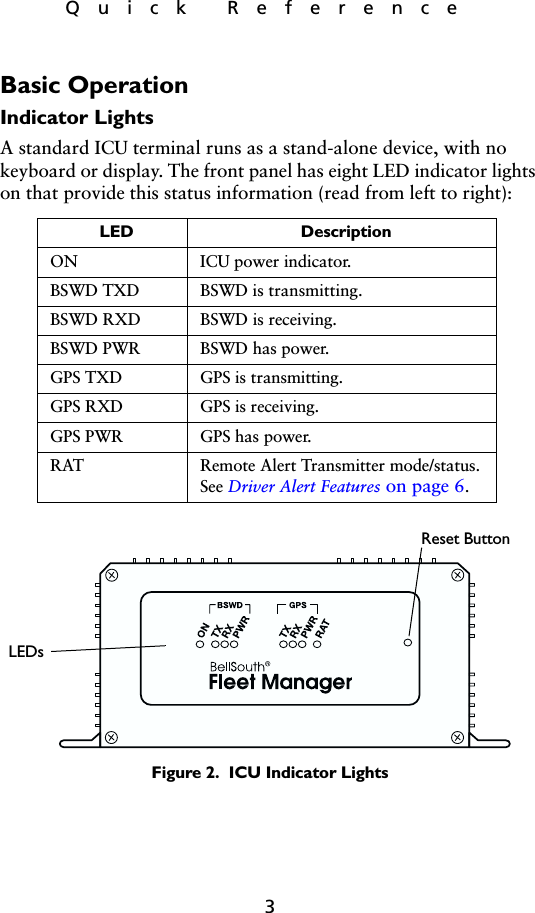
Quick Reference
Contents
1.
Quick Reference
2.
OEM Guide (RIM 902M)
3.
Users Guide
4.
Response to CRN 18597
5.
Page1 Statement
6.
MPE Measurement
Quick Reference
Navigation menu
Upload a User Manual
Namespaces
Wiki Guide
HTML
PDF
Info
Views
User Manual
Discussion / Help
Navigation