Leidos LPR902M-ICU-0 AVL GPS User Manual MG QRG
Science Application International Corporation AVL GPS MG QRG
Leidos >
Contents
Quick Reference
ICU Terminal

ICU Terminal
2000 SYMBOL TECHNOLOGIES, INC. All rights reserved.
Symbol reserves the right to make changes to any product to improve reliability,
function, or design.
Symbol does not assume any product liability arising out of, or in connection with, the
application or use of any product, circuit, or application described herein.
No license is granted, either expressly or by implication, estoppel, or otherwise under
any patent right or patent, covering or relating to any combination, system, apparatus,
machine, material, method, or process in which Symbol products might be used. An
implied license only exists for equipment, circuits, and subsystems contained in Symbol
products.
Symbol and the Symbol logo are a registered trademarks of Symbol Technologies, Inc.
Other product names mentioned in this manual may be trademarks or registered
trademarks of their respective companies and are hereby acknowledged.
Symbol Technologies, Inc.
One Symbol Plaza
Holtsville, N.Y. 11742-1300
http://www.symbol.com
Patents
This product is covered by one or more of the following U.S. and foreign Patents:
U.S. Patent No. 4,460,120; 4,496,831; 4,593,186; 4,603,262; 4,607,156; 4,652,750;
4,673,805; 4,736,095; 4,758,717; 4,816,660; 4,845,350; 4,896,026; 4,897,532;
4,923,281; 4,933,538; 4,992,717; 5,015,833; 5,017,765; 5,021,641; 5,029,183;
5,047,617; 5,103,461; 5,113,445; 5,130,520; 5,140,144; 5,142,550; 5,149,950;
5,157,687; 5,168,148; 5,168,149; 5,180,904; 5,216,232; 5,229,591; 5,230,088;
5,235,167; 5,243,655; 5,247,162; 5,250,791; 5,250,792; 5,260,553; 5,262,627;
5,262,628; 5,266,787; 5,278,398; 5,280,162; 5,280,163; 5,280,164; 5,280,498;
5,304,786; 5,304,788; 5,306,900; 5,321,246; 5,324,924; 5,337,361; 5,367,151;
5,373,148; 5,378,882; 5,396,053; 5,396,055; 5,399,846; 5,408,081; 5,410,139;
5,410,140; 5,412,198; 5,418,812; 5,420,411; 5,436,440; 5,444,231; 5,449,891;
5,449,893; 5,468,949; 5,471,042; 5,478,998; 5,479,000; 5,479,002; 5,479,441;
5,504,322; 5,519,577; 5,528,621; 5,532,469; 5,543,610; 5,545,889; 5,552,592;
5,557,093; 5,578,810; 5,581,070; 5,589,679; 5,589,680; 5,608,202; 5,612,531;
5,619,028; 5,627,359; 5,637,852; 5,664,229; 5,668,803; 5,675,139; 5,693,929;
5,698,835; 5,705,800; 5,714,746; 5,723,851; 5,734,152; 5,734,153; 5,742,043;
5,745,794; 5,754,587; 5,762,516; 5,763,863; 5,767,500; 5,789,728; 5,789,731;
5,808,287; 5,811,785; 5,811,787; 5,815,811; 5,821,519; 5,821,520; 5,823,812;
5,828,050; 5,850,078; 5,861,615; 5,874,720; 5,875,415; 5,900,617; 5,902,989;
5,907,146; 5,912,450; 5,914,478; 5,917,173; 5,920,059; 5,923,025; 5,929,420;
5,945,658; 5,945,659; 5,946,194; 5,959,285; 6,002,918; 6,021,947; 6,047,892;
6,050,491; 6,053,413; 6,056,200; 6,065,678; 6,067,297; 6,068,190; D305,885;
D341,584; D344,501; D359,483; D362,453; D363,700; D363,918; D370,478;
D383,124; D391,250; D405,077; D406,581; D414,171; D414,172, D419,548;
D423,468; D424,035.
Invention No. 55,358; 62,539; 69,060; 69,187 (Taiwan); No. 1,601,796; 1,907,875;
1,955,269 (Japan).
European Patent 367,299; 414,281; 367,300; 367,298; UK 2,072,832; France 81/03938;
Italy 1,138,713.
rev. 06/00
1
Quick Reference
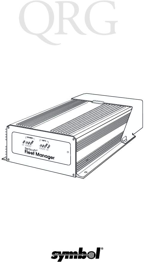
Introduction
The SAIC In-Vehicle Control Unit (ICU) is a rugged computer
developed by Symbol for SAIC, and used as a platform for in-
vehicle communications. It provides wireless network
communications and two serial ports.
The ICU uses an 80386 processor and supports an MS-DOS
Operating System using industry standard protocols.
About This Guide
This manual describes the ICU’s basic features. Specific topics
include:
•Parts of an ICU on page 2
•Basic Operation on page 3
-Indicator Lights on page 3
-Ports and Connectors on page 4
-Resetting the ICU on page 5
•Driver Alert Features on page 6
•Basic Troubleshooting on page 8
•Service Information on page 10
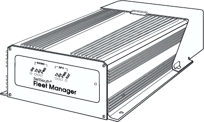
Figure 1. ICU with Access Denial Cover in Place

2
ICU Terminal
Parts of an ICU
Symbol Parts
The ICU has these parts and features provided by Symbol:
• 2 MB of DRAM, expandable to 4MB
• 2 MB Flash Drive, expandable to 8MB
• RS-232 COM1 serial port
• In-Vehicle Alert (IVA) port
• 2 RAT Key Fobs
• Connectors for RAT, GPS and BSWD antennas
• Access Denial Cover
• Quick Reference Guide
SAIC Parts
The ICU also requires these parts provided by SAIC:
• RAT, GPS and BSWD antennas and cables
• Power Input cable with 2 fuses
• IVA cables
• Manufacturing Mode cable for communication with a PC
• Ground cable required for installation
• Fasteners required for installation
ICU Software
The ICU terminal runs SAIC custom software from a DOS
Operating System.
3
Quick Reference
Basic Operation
Indicator Lights
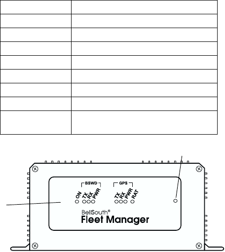
A standard ICU terminal runs as a stand-alone device, with no
keyboard or display. The front panel has eight LED indicator lights
on that provide this status information (read from left to right):
Figure 2. ICU Indicator Lights
LED Description
ON ICU power indicator.
BSWD TXD BSWD is transmitting.
BSWD RXD BSWD is receiving.
BSWD PWR BSWD has power.
GPS TXD GPS is transmitting.
GPS RXD GPS is receiving.
GPS PWR GPS has power.
RAT Remote Alert Transmitter mode/status.
See Driver Alert Features on page 6.
Reset Button
LEDs
4
ICU Terminal
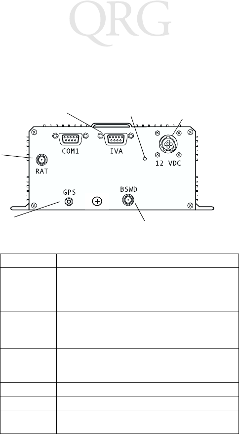
Ports and Connectors
The connector panel of the ICU unit has two ports, a power
connector, the RAT programming button and three antenna
connectors. The table describes these ports and connectors.
Figure 3. ICU Ports and Connectors (SAIC model)
Connector Function
COM1 An RS-232 serial port with a 9-pin connector that
can be used to communicate with devices such as
laptop PCs. It connects to an RS-232 port on a Host
PC using a specialized null modem cable.
IVA A connector for the In-Vehicle Alert (IVA) cable.
12 VDC The Power Input cable plugs into this connector to
provides power to the unit.
RAT
Programming
Button
A recessed button that allows you to program the
Remote Alert Transmitter (RAT). See page 6 for
more information.
RAT A connector for the RAT radio antenna.
GPS A connector for the GPS radio antenna.
BSWD A connector for the BSWD (Mobitex) radio
antenna.
RAT
Power Input Cable
Connector
In-Vehicle Alert (IVA)
Connector
Antenna
Connector
GPS
Antenna Connector BSWD Antenna Connector
RAT Programming
Button
5
Quick Reference
Resetting the ICU
If the ICU stops responding, or stops receiving and sending data,
you may need to reset it. The Reset button is a recessed switch
located on the front panel, to the right of the LEDs.
To reset the unit, press and hold the Reset switch for more than one
second, and then release it.
Te m p e r a t u r e
Operating Temperature range: -20°C to +60°C
Storage Temperature range: -40°C to +70°C
6
ICU Terminal
Driver Alert Features
Each ICU unit has a Remote Alert Transmitter (RAT). The RAT is
a device that allows vehicle drivers to send a message if they need
immediate assistance. There are two ways for a driver to trigger an
alert:
• In-Vehicle Alert button (IVA)
• RAT Wireless Key Fob button
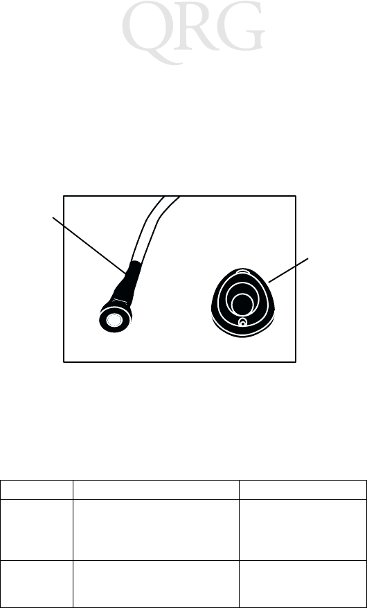
Figure 4. Driver Alert Options
Sending an Alert
When the driver triggers an alert, the ICU immediately wakes up
and sets a bit in Port 211 so that the software can transmit an alert.
The table below describes the two methods for a driver to send a
RAT alarm.
Alarm Type How to Send It Requirements
IVA Press one of the IVA buttons that
are directly wired into the ICU
unit: one in the vehicle cab, and
one in the back of the truck.
The driver must be in
the cab or the back of
the vehicle.
RAT Key
Fob
Press the button on the RAT Key
Fob.
Driver must be within
150 feet of the vehicle,
and within line of sight.
IVA Cable
and Button
RAT Key
Fob
7
Quick Reference
Programming the Remote Alert Transmitter (RAT)
The ICU must be programmed to recognize a transmission from a
wireless RAT Key Fob. Each vehicle driver will have a RAT Key Fob.
Programming a RAT Button
To program the ICU to recognize a particular RAT Key Fob:
1. Remove the Access Denial Cover to get access to the RAT Pro-
gramming button located on the ICU connector panel.
2. Press and release the RAT Programming button on the ICU.
Use a pen tip or similar object to press the recessed button. On
the front panel, the LED for the RAT will show a solid light,
indicating that the terminal is in Learn mode.
3. When you see the solid RAT LED, you have 10 seconds to
press the Key Fob button in this sequence:
a. Press and release the RAT Key Fob button.
b. Press and hold the RAT Key Fob button until the RAT
LED indicator starts to blink on the ICU.
4. The blinking light shows that the RAT Key Fob has been suc-
cessfully programmed. It will trigger a RAT alarm if a driver
presses the RAT button on the Key Fob.
Deleting a RAT Button
This procedure deletes the programming information for all RAT
Key Fobs programmed into an ICU:
1. Remove the Access Denial Cover to get access to the RAT Pro-
gramming button located on the back panel of the ICU.
2. Press and hold the RAT Programming button on the ICU. Use
a pen tip or similar object to press the recessed button. On the
front panel, the RAT LED shows a solid light.
3. Wait for the RAT LED to turn off. Then release the RAT Pro-
gramming button.
4. All programming information has now been deleted from the
ICU. Pressing a RAT Key Fob button will not trigger an alert.
Note that this does not affect the IVA Alert buttons.

8
ICU Terminal
Basic Troubleshooting
This table provides guidelines for troubleshooting some basic
problems on the ICU. If you cannot solve the problem using these
guidelines, please contact Customer Service for advanced
troubleshooting and repair.
Problem Action
Terminal does
not start.
Make sure the External Power cable is connected to
the ICU terminal and to a vehicle power source.
Check the vehicle battery. If it is depleted (dead), re-
place the vehicle battery.
Make sure the Vehicle Accessory Power (ACC) wire is
connected to a switched 12 VDC Power Source. If it is
not, then vehicle ignition will not wake the terminal.
In-Vehicle Alert
(IVA) does not
work.
Make sure the IVA cable has not come unplugged from
the ICU terminal .
Make sure neither of the IVA buttons has been stuck
in the “on” position. If this happens, it prevents either
IVA cable or the RAT Key Fob buttons from working.
Check for obvious problems with the cable, or with
the ICU hardware.
Remote Alert
(RAT) does not
work.
Make sure the terminal has been programmed to work
with the RAT Key Fob. Clear the RAT Programming
from the ICU. Then reprogram it with the existing
RAT Key Fob. See page 7 for instructions.
The RAT Key Fob may be faulty. Repeat the program-
ming process with a new RAT Key Fob.
Make sure neither of the IVA buttons has been stuck
in the “on” position. If this happens, it prevents either
IVA cable or the RAT Key Fob buttons from working.

9
Quick Reference
GPS data is miss-
ing or incorrect.
Make sure the GPS antenna cable is in good condition,
and connected securely to the terminal.
The vehicle may be in an area where there is poor GPS
coverage (e.g., parkades, tunnels, deep valleys or areas
with many tall buildings).
There may be a problem with either the software, or
with the GPS radio. Contact Customer Service for ad-
vanced troubleshooting and repair.
Terminal is not
receiving data or
transmitting
data (BSWD and
RAT radios).
Make sure the antenna cables are in good condition,
and connected securely to the terminal.
Check to see if there are problems on the network.
You may be in an area of poor coverage. Drive to an
area where you know the radio coverage is adequate.
There may be a problem with either the software, or
with an internal radio. Contact Customer Service for
advanced troubleshooting and repair.
Problem Action

10
ICU Terminal
Service Information
Before you use the unit, it must be configured to operate in your
facility’s network and run your applications.
If you have a problem running your unit or using your equipment,
contact your facility’s Technical or Systems Support. If there is a
problem with the equipment, they will contact the Symbol Support
Center:
Warranty
Symbol Technologies, Inc. (“Symbol”) manufactures its hardware products in
accordance with industry-standard practices. Symbol warrants that for a period of
twelve (12) months from date of shipment, products will be free from defects in
materials and workmanship.
This warranty is provided to the original owner only and is not transferable to any third
party. It shall not apply to any product (i) which has been repaired or altered unless
done or approved by Symbol, (ii) which has not been maintained in accordance with
any operating or handling instructions supplied by Symbol, (iii) which has been
subjected to unusual physical or electrical stress, misuse, abuse, power shortage,
negligence or accident or (iv) which has been used other than in accordance with the
product operating and handling instructions. Preventive maintenance is the
responsibility of customer and is not covered under this warranty.
Wear items and accessories having a Symbol serial number, will carry a 90-day limited
warranty. Non-serialized items will carry a 30-day limited warranty.
United States 1-800-653-5350 Canada 905-629-7226
United Kingdom 0800 328 2424 Asia/Pacific 337-6588
Australia 1-800-672-906 Austria 1-505-5794
Denmark 7020-1718 Finland 9 5407 580
France 01-40-96-52-21 Germany 6074-49020
Italy 2-484441 Mexico 5-520-1835
Netherlands 315-271700 Norway 66810600
South Africa 11-4405668 Spain 9-1-320-39-09
Sweden 84452900
Latin America Sales Support 1-800-347-0178 Inside US
+1-561-483-1275 Outside US
Europe/Mid-East Distributor
Operations
Contact local distributor or call
+44 118 945 7360
11
Quick Reference
Warranty Coverage and Procedure
During the warranty period, Symbol will repair or replace defective products returned
to Symbol’s manufacturing plant in the US. For warranty service in North America, call
the Symbol Support Center at 1-800-653-5350. International customers should contact
the local Symbol office or support center. If warranty service is required, Symbol will
issue a Return Material Authorization Number. Products must be shipped in the
original or comparable packaging, shipping and insurance charges prepaid. Symbol
will ship the repaired or replacement product freight and insurance prepaid in North
America. Shipments from the US or other locations will be made F.O.B. Symbol’s
manufacturing plant.
Symbol will use new or refurbished parts at its discretion and will own all parts
removed from repaired products. Customer will pay for the replacement product in
case it does not return the replaced product to Symbol within 3 days of receipt of the
replacement product. The process for return and customer’s charges will be in
accordance with Symbol’s Exchange Policy in effect at the time of the exchange.
Customer accepts full responsibility for its software and data including the appropriate
backup thereof.
Repair or replacement of a product during warranty will not extend the original
warranty term.
Symbol’s Customer Service organization offers an array of service plans, such as on-
site, depot, or phone support, that can be implemented to meet customer’s special
operational requirements and are available at a substantial discount during warranty
period.
General
Except for the warranties stated above, Symbol disclaims all warranties, express or
implied, on products furnished hereunder, including without limitation implied
warranties of merchantability and fitness for a particular purpose. The stated express
warranties are in lieu of all obligations or liabilities on part of Symbol for damages,
including without limitation, special, indirect, or consequential damages arising out of
or in connection with the use or performance of the product.
Seller’s liability for damages to buyer or others resulting from the use of any product,
shall in no way exceed the purchase price of said product, except in instances of injury
to persons or property.
Some states (or jurisdictions) do not allow the exclusion or limitation of incidental or
consequential damages, so the proceeding exclusion or limitation may not apply to you.

12
ICU Terminal
Regulatory Information
Radio Frequency Interference Requirements
This device has been tested and found to comply with the limits for a Class B digital
device pursuant to Part 15 of the Federal Communications Commissions Rules and
Regulation. These limits are designed to provide reasonable protection against harmful
interference when the equipment is operated in a commercial environment. This
equipment generates, uses, and can radiate radio frequency energy and, if not installed
and used in accordance with the instruction manual, may cause harmful interference to
radio communications. Operation of this equipment in a residential area is likely to
cause harmful interference in which case the user will be required to correct the
interference at his own expense.
However, there is no guarantee that interference will not occur in a particular
installation. If the equipment does cause harmful interference to radio or television
reception, which can be determined by turning the equipment off and on, the user is
encouraged to try to correct the interference by one or more of the following measures:
• Re-orient or relocate the receiving antenna.
• Increase the separation between the equipment and receiver.
• Connect the equipment into an outlet on a circuit different from that which the
receiver is connected.
• Consult the dealer or an experienced radio/TV technician for help.
This device complies with FCC Part 15. Operation is subject to the following two
conditions: (1) this device may not cause harmful interference and (2) this device must
accept any interference received, including interference that may cause undesired
operation.
Radio Frequency Interference Requirements - Canada
This device complies with RSS 210 of Industry & Science Canada. Operation is subject
to the following two conditions: (1) this device may not cause harmful interference and
(2) this device must accept any interference received, including interference that may
cause undesired operation.
This Class A digital apparatus complies with Industry Canada Standard ICES-003.
Cet appareil numérique de la classe A est conform à la norme NMB-003 d’Industrie
Canada.
13
Quick Reference

72-43383-01
Revision A— September 2000
Symbol Technologies, Inc. One Symbol Plaza Holtsville, NY 11742-1300