Leidos NORMARC7013 7013 Dual Frequency Localizer User Manual Installation and Commissioning Handbook Vol 1
Lockheed Martin Air Traffic Management 7013 Dual Frequency Localizer Installation and Commissioning Handbook Vol 1
Leidos >
Contents
- 1. Normarc 7000 Instr Landing Sys Installation and Commissioning Handbook Vol1
- 2. Normarc 7000 ILS Installation and Commissioning Handbook Vol2
- 3. Normarc 7000 ILS Installation and Commissioning Handbook Vol 1 and 2
- 4. Normarc 7013 ILS General Description
- 5. Normarc 7013 ILS Technical Handbook
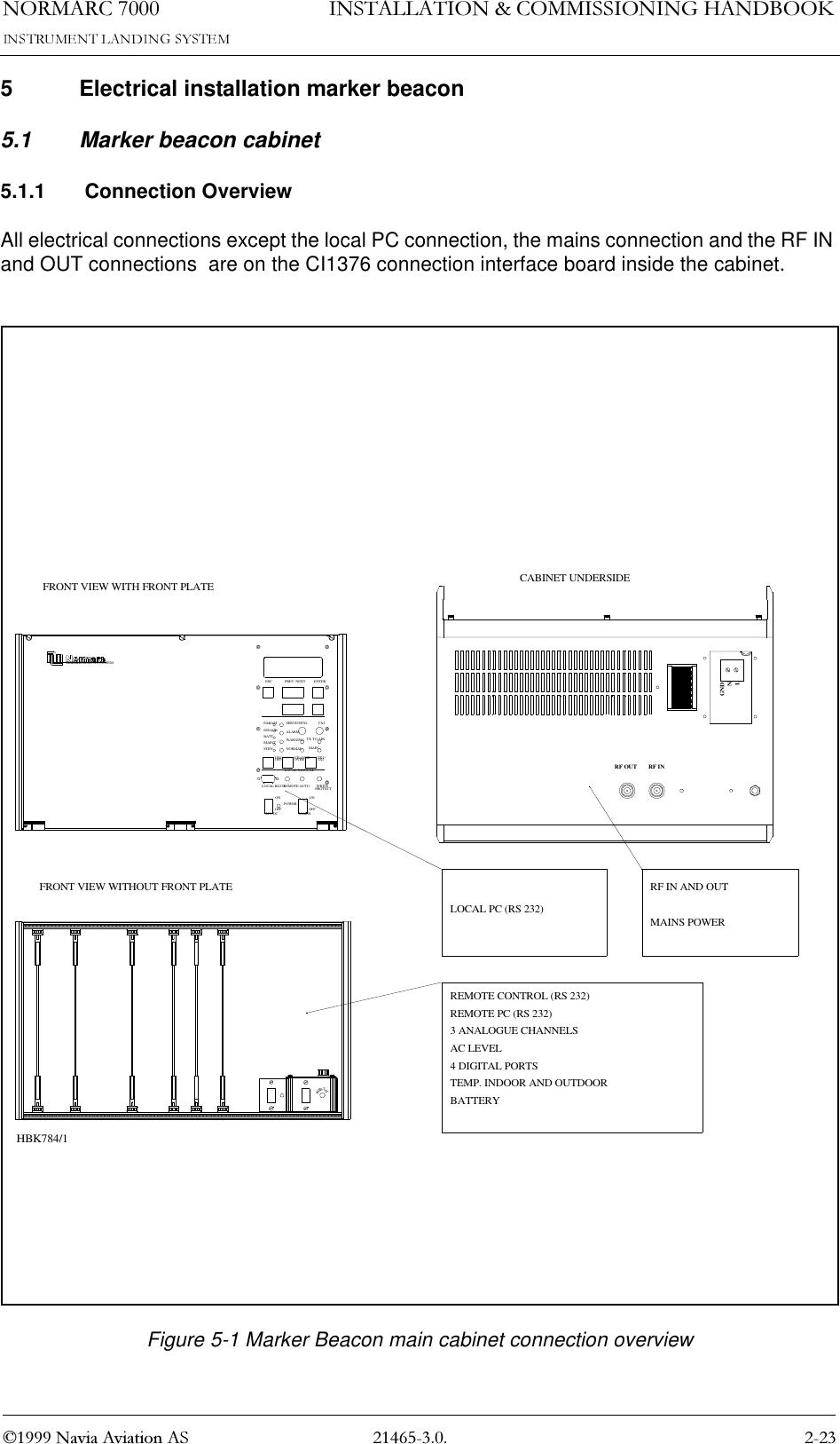
Normarc 7000 Instr Landing Sys Installation and Commissioning Handbook Vol1

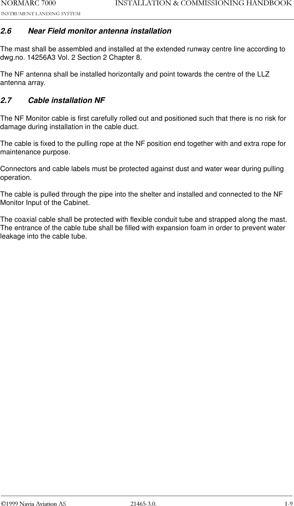


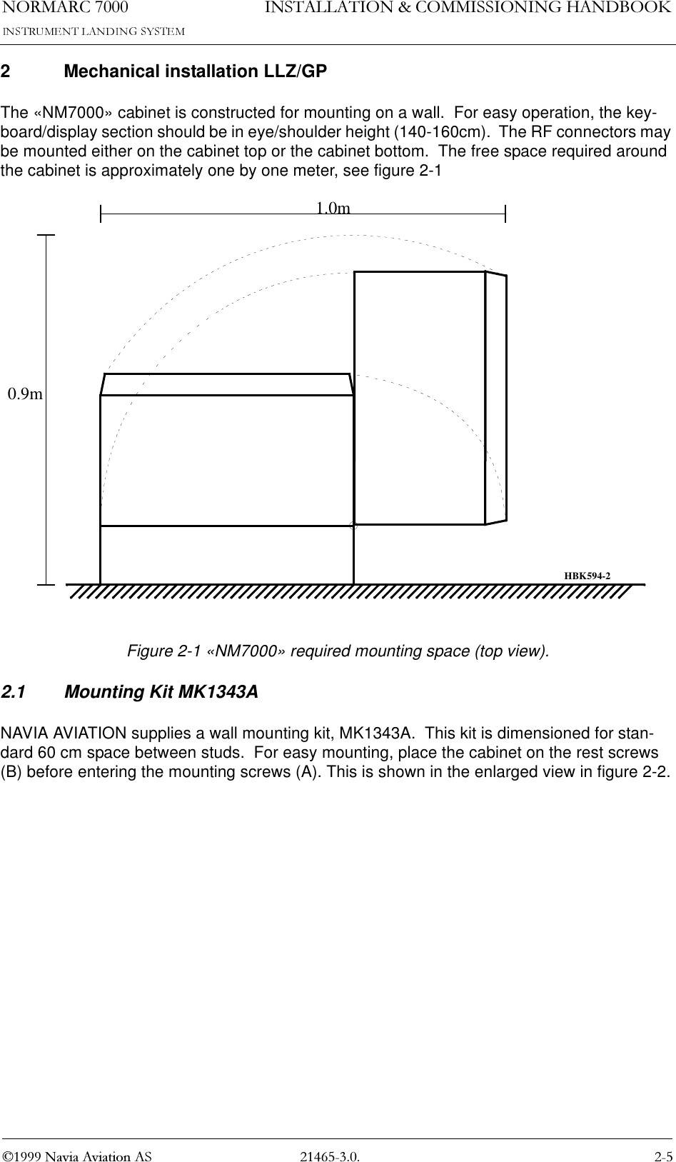


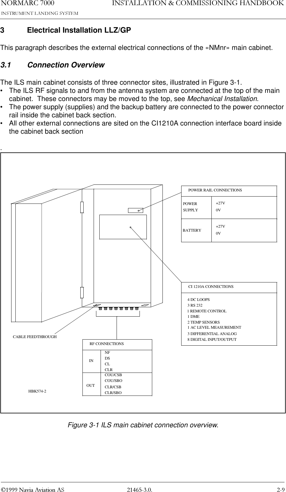
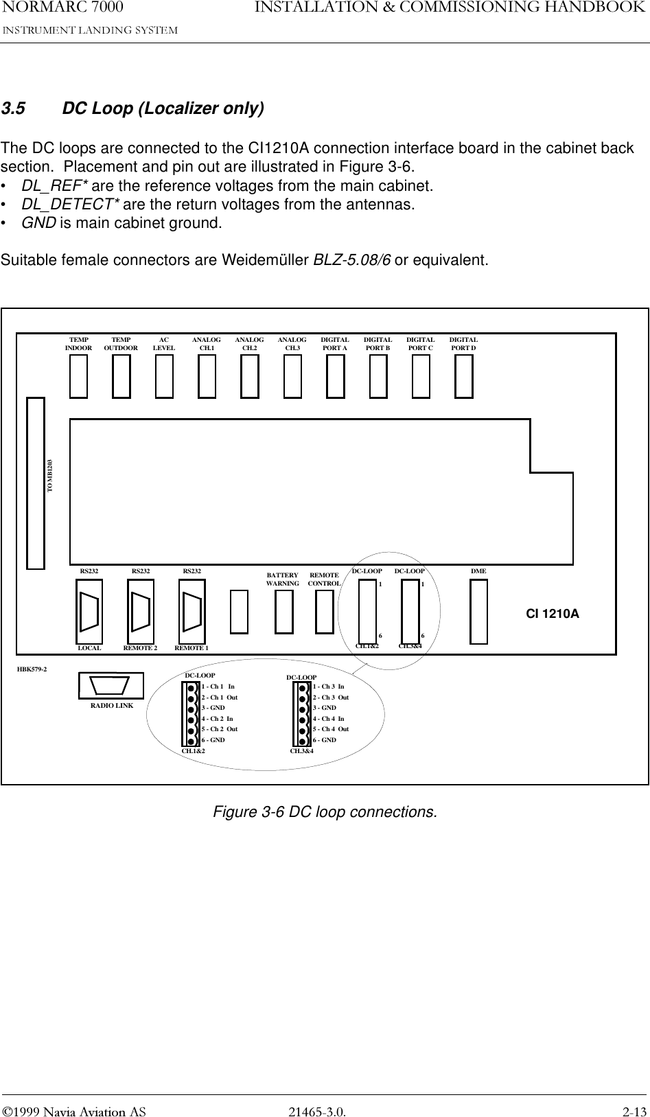
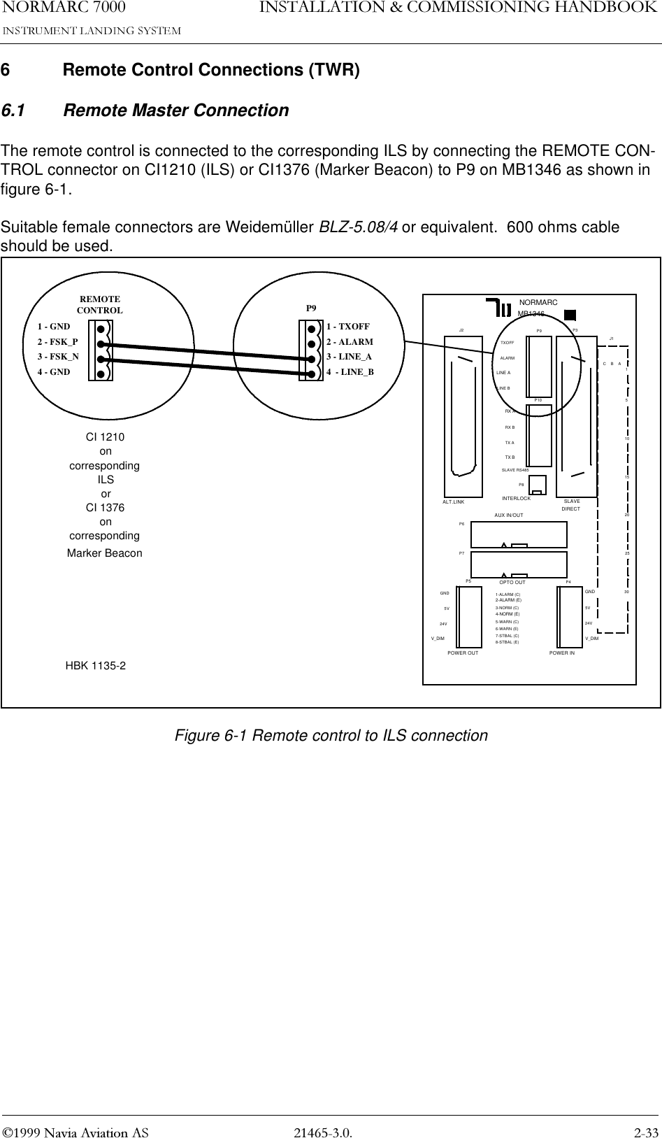
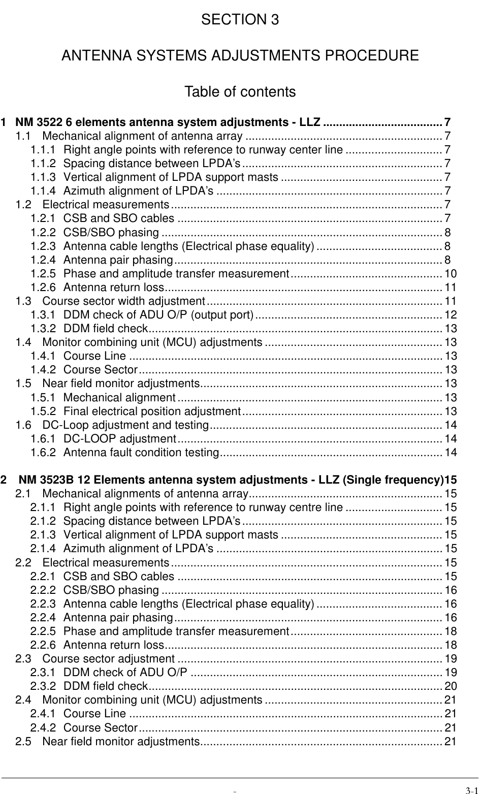
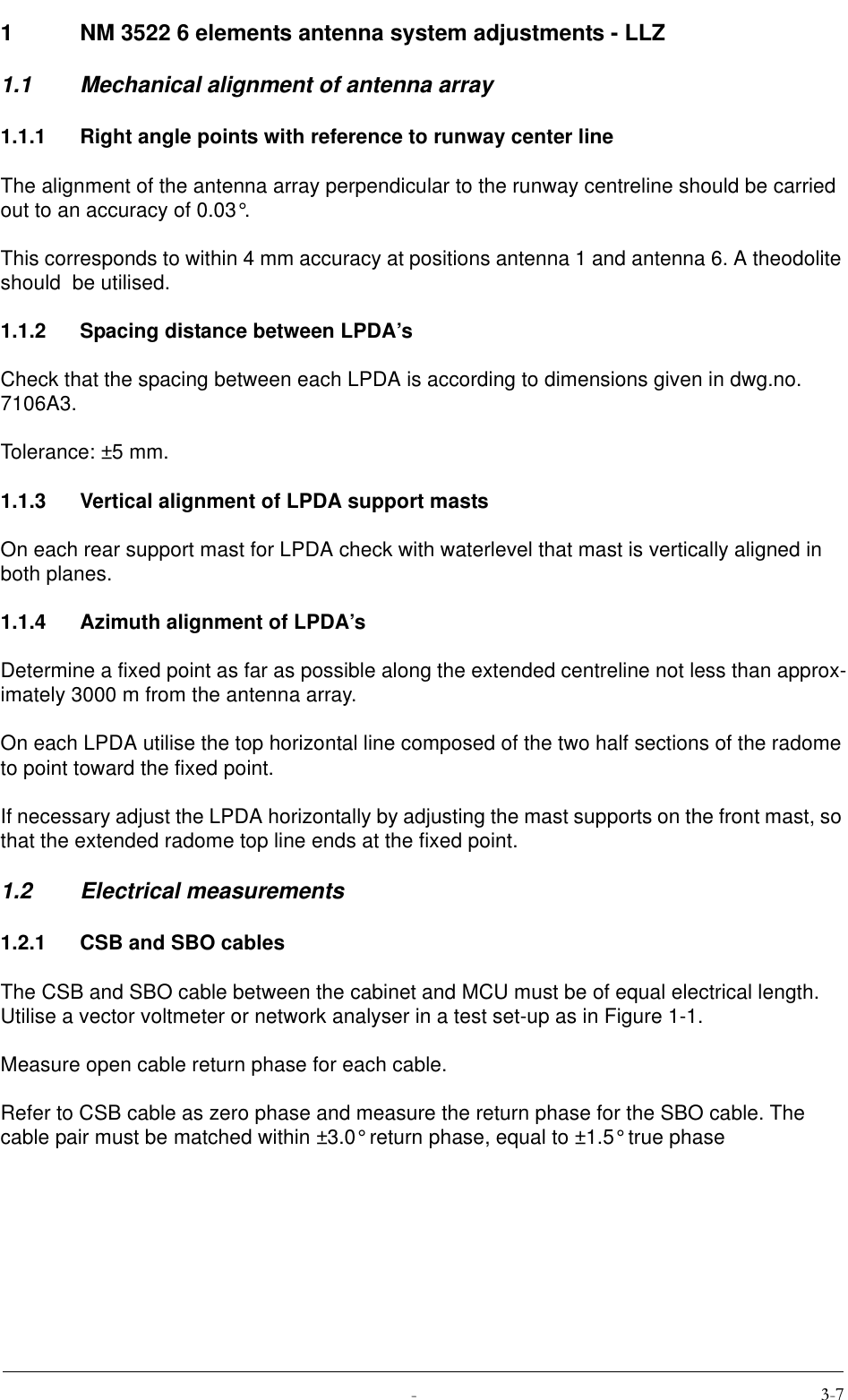
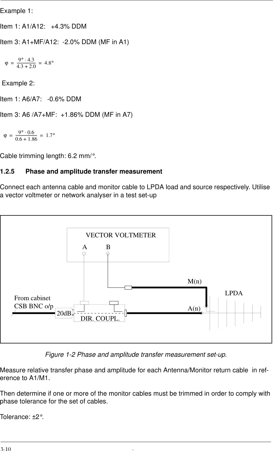
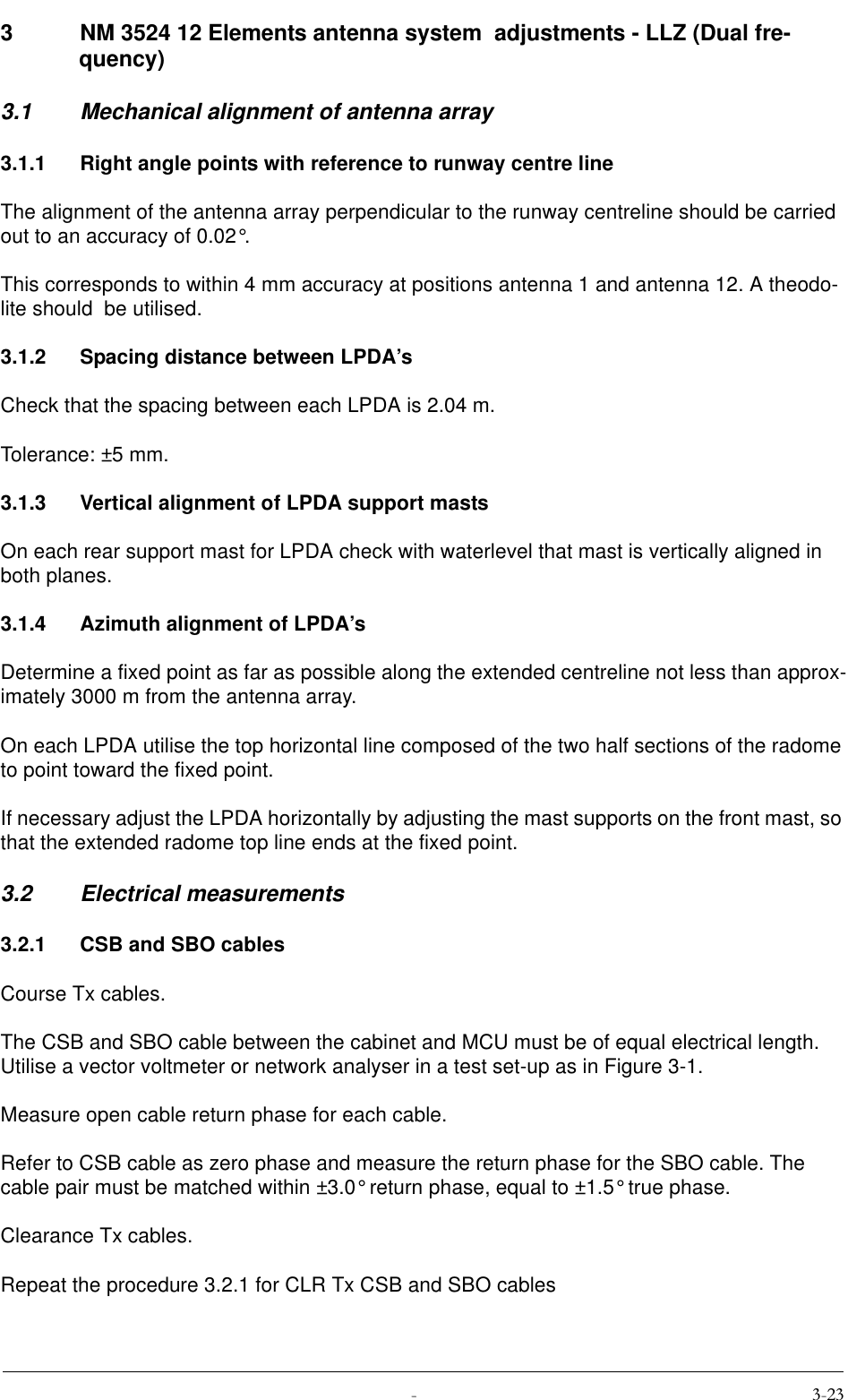
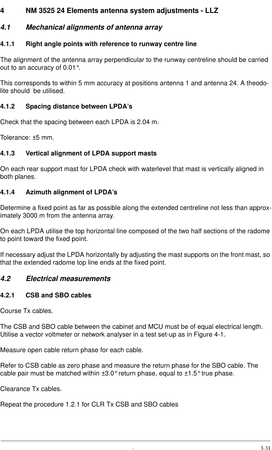
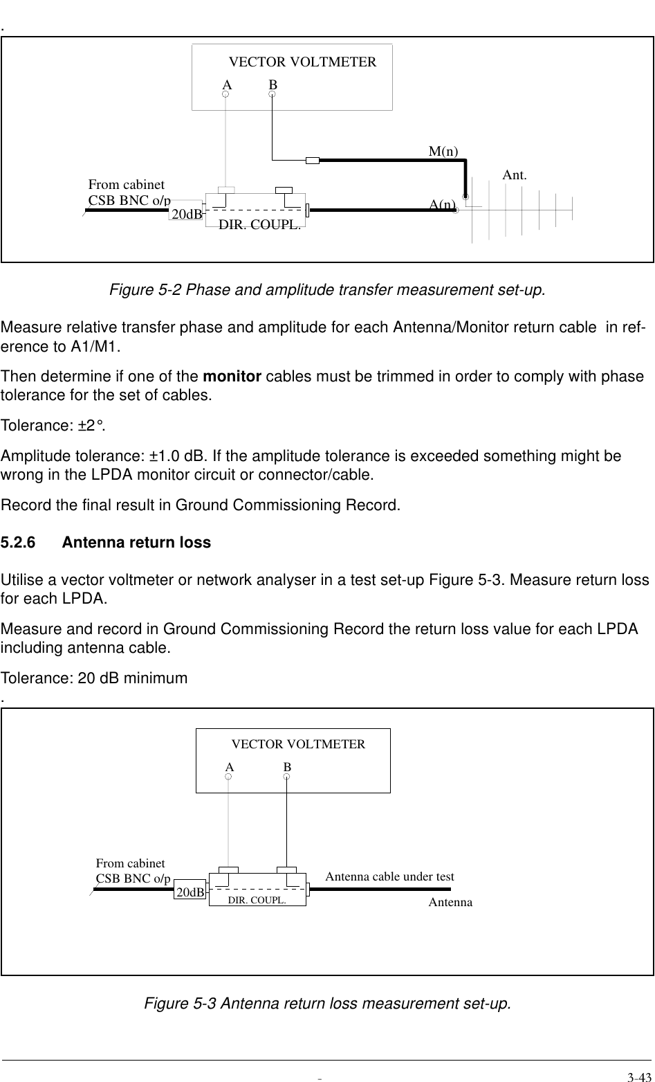
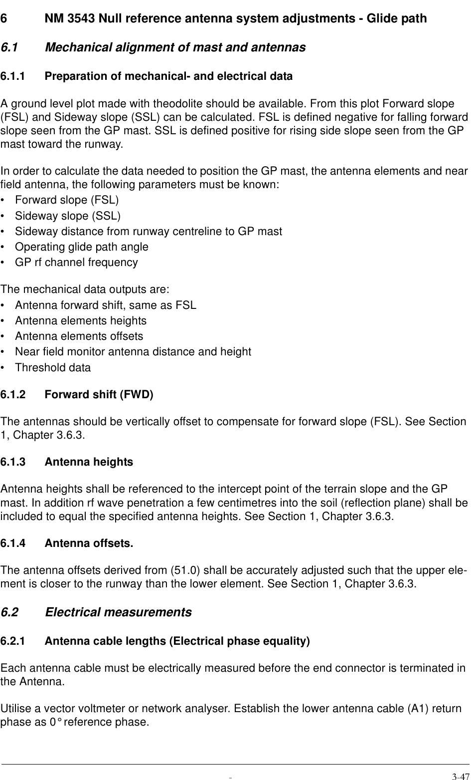
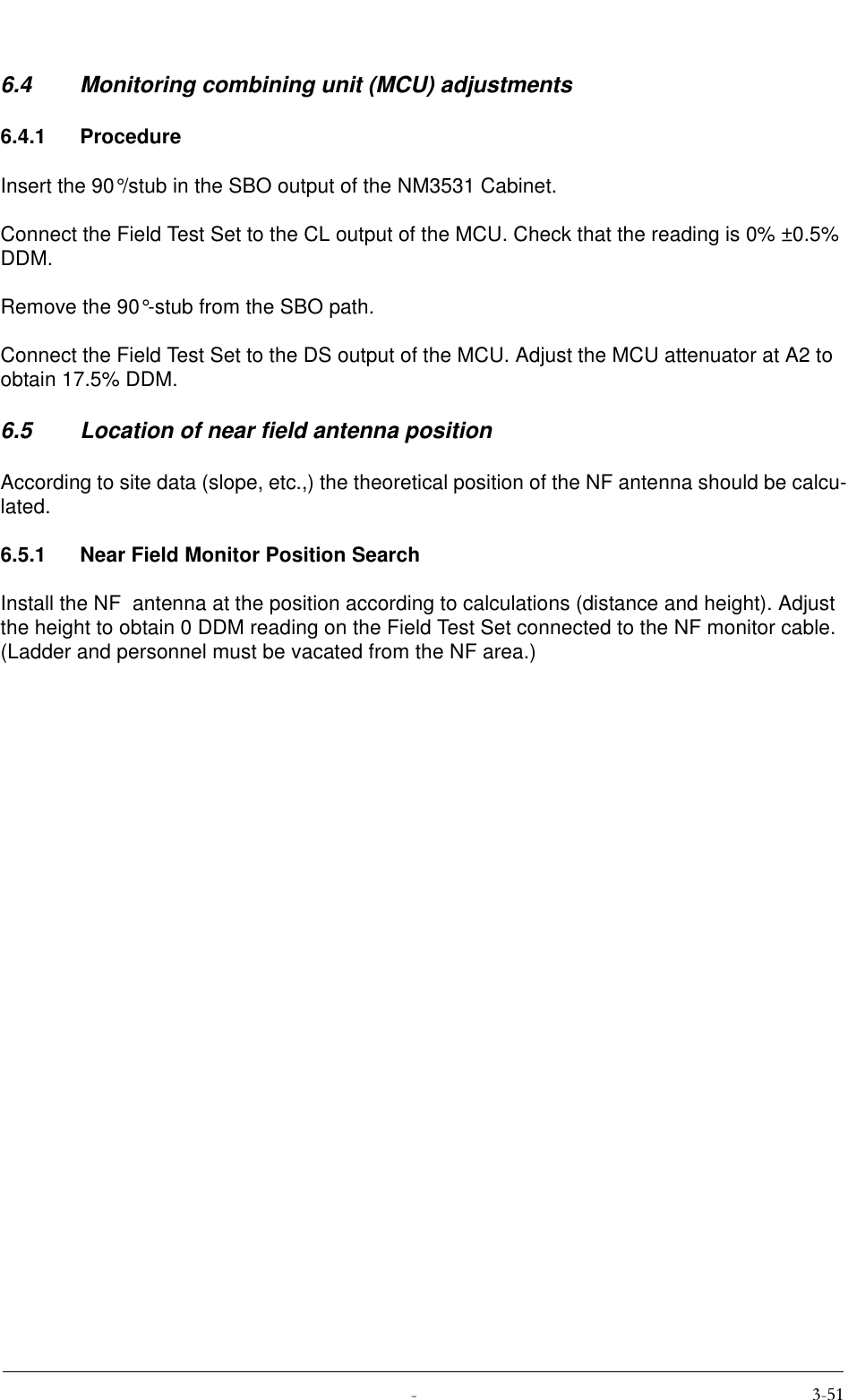
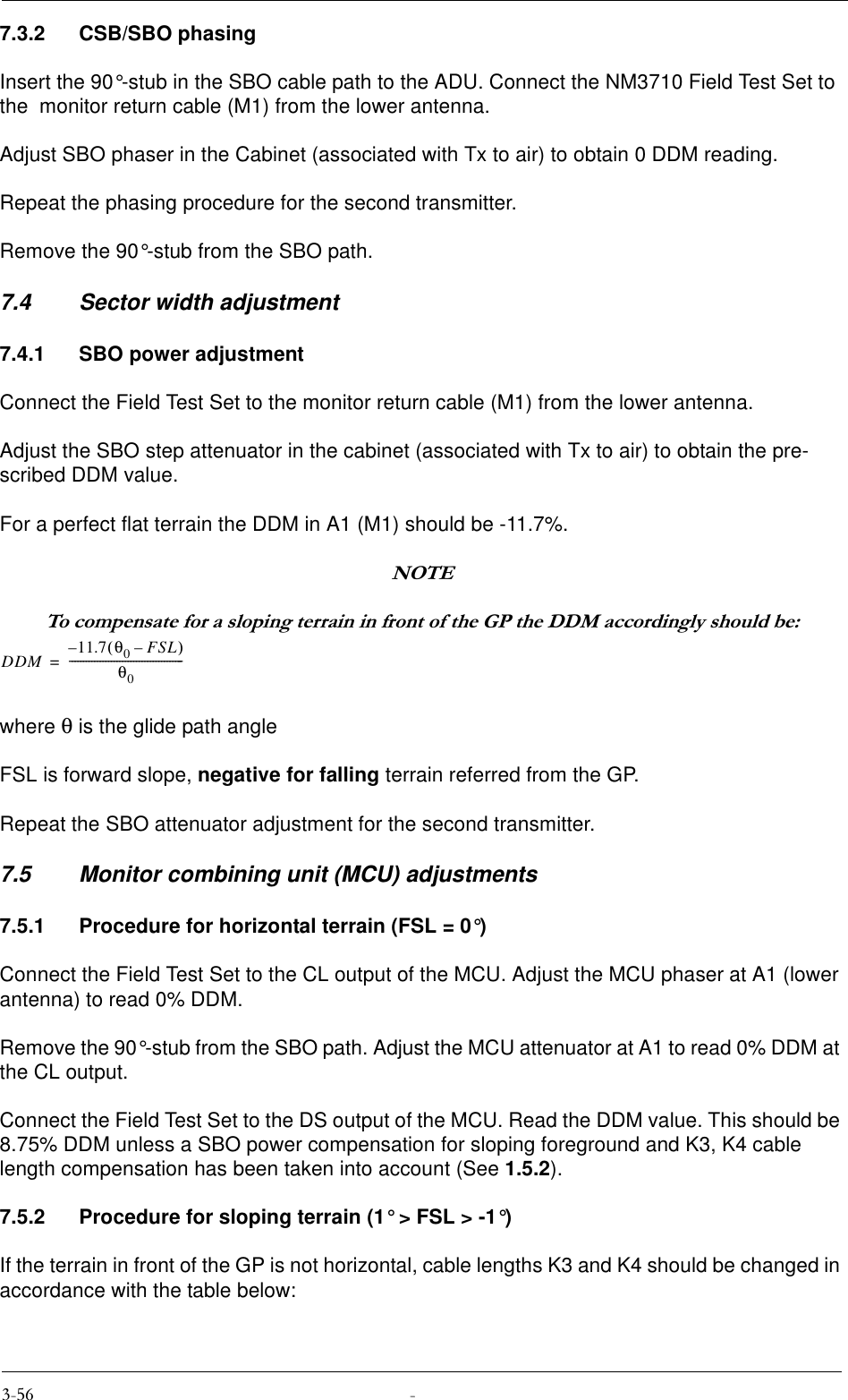
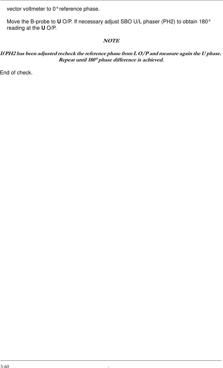
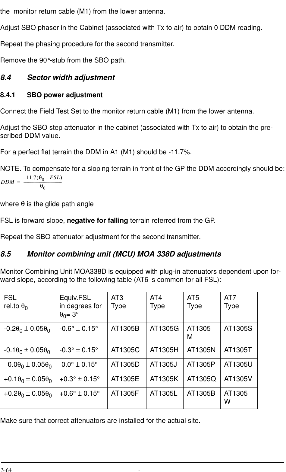
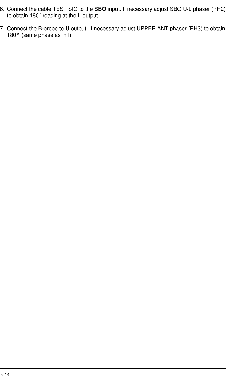
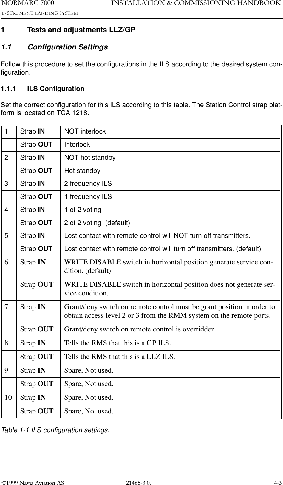
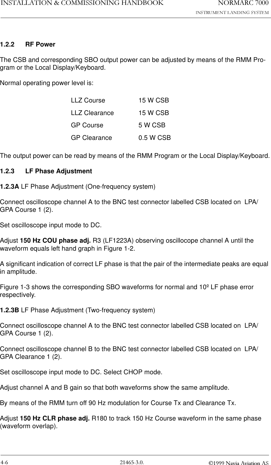
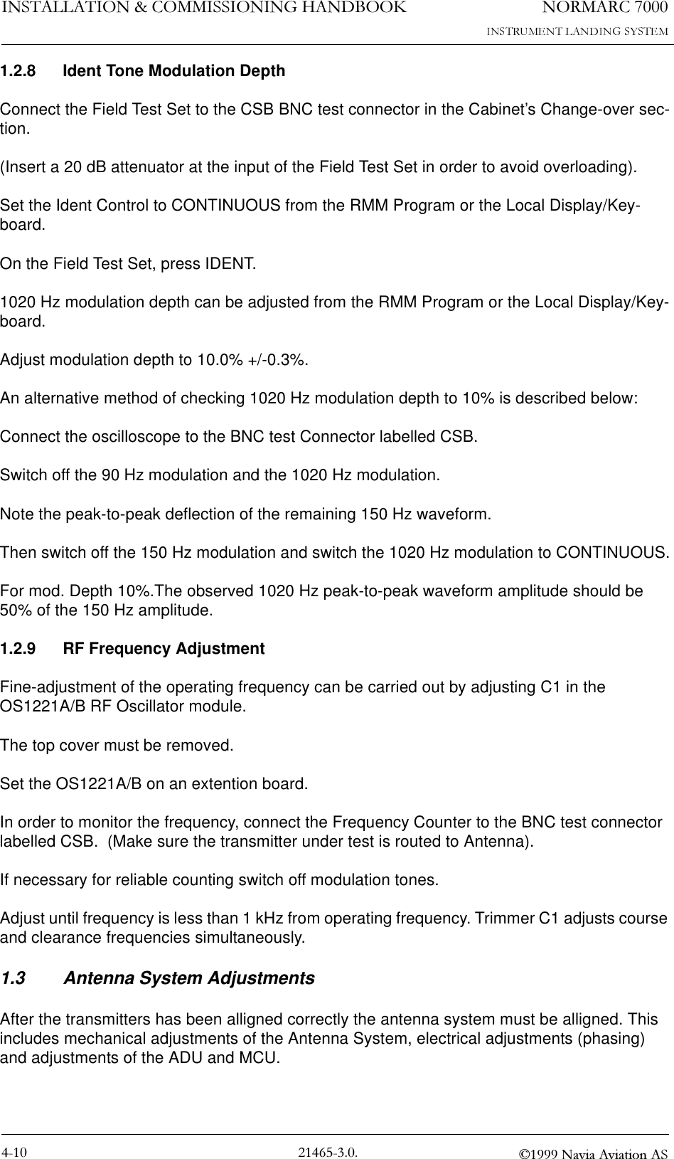
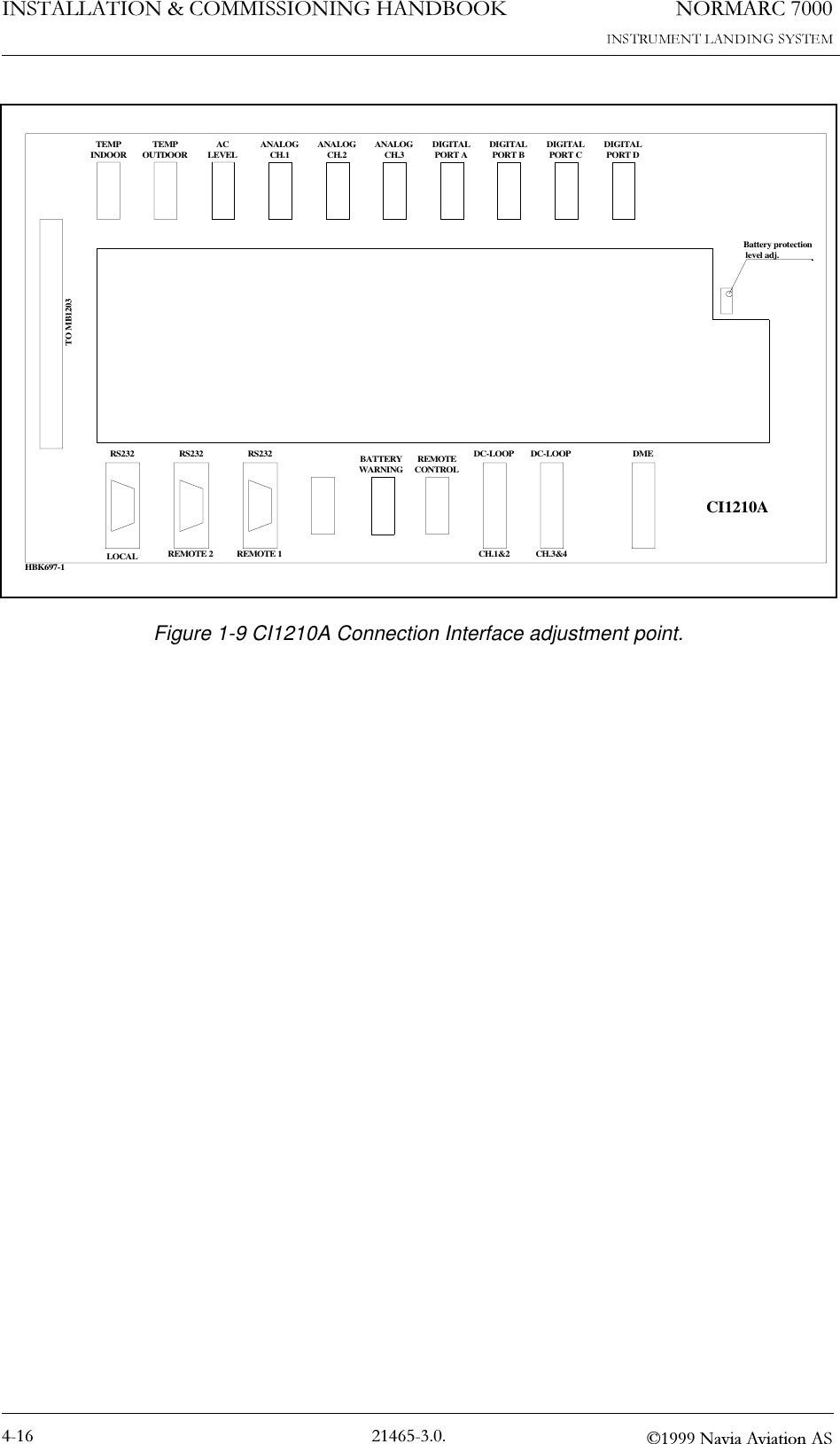
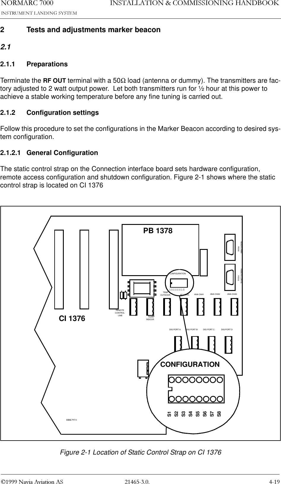
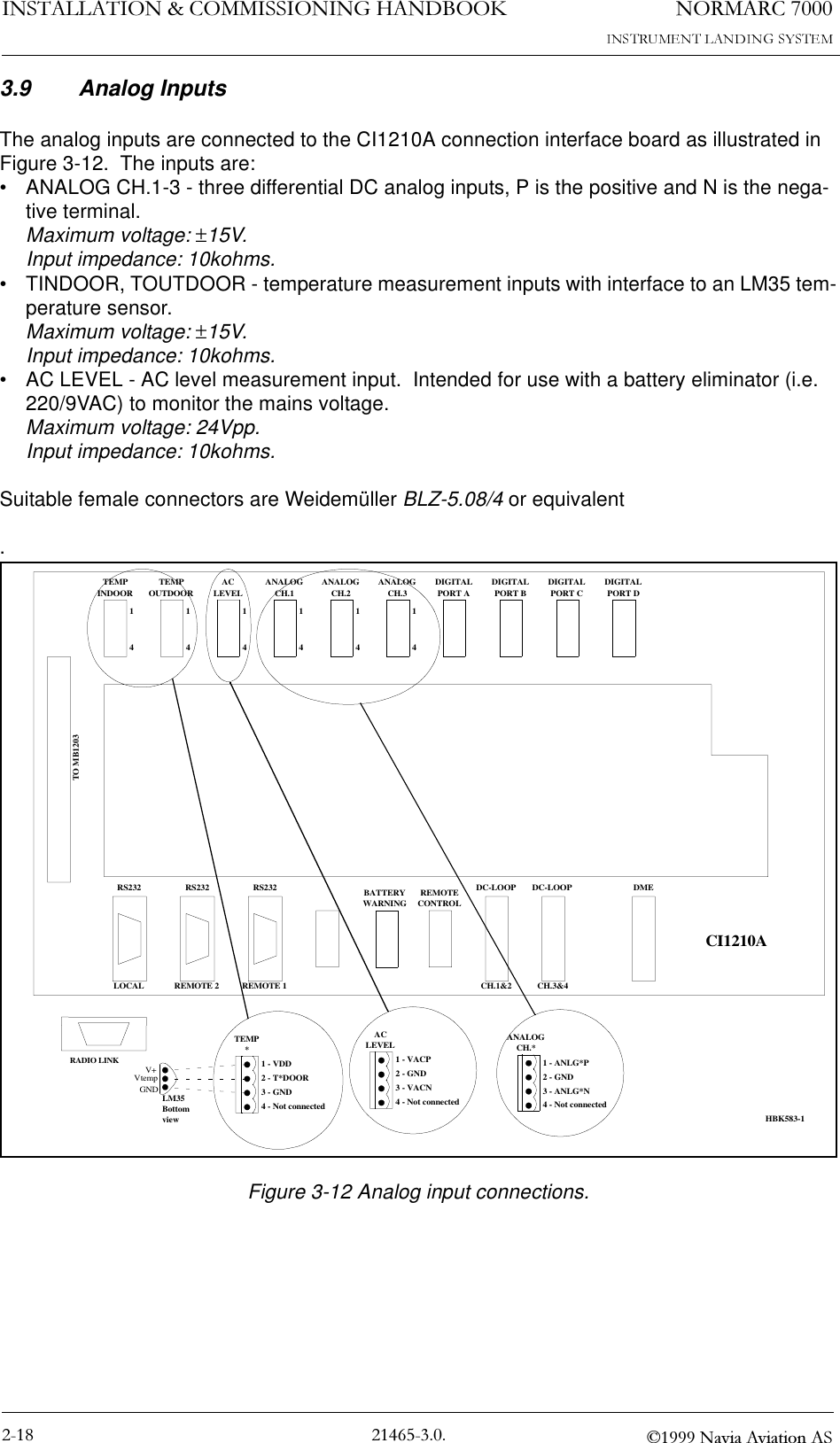
![1250$5&,167$//$7,21&200,66,21,1*+$1'%22. 1DYLD$YLDWLRQ$63.6 Remote Control ( CABINET)The remote control is connected to the CI1210A connection interface board as illustrated in Figure 3-7. The connection of the remote control, remote slave panel and interlock switch is done at the remote control site and covered in Section 2 6.1-6.4.•FSK_[P,N] is the modem line pair.•GND is main cabinet ground.For normal FSK modem operation the straps S9-11 on CI1210A should be mounted.A suitable female connector is Weidemüller BLZ-5.08/4 or equivalent.Figure 3-7 Remote control connection.TEMPINDOOR TEMPOUTDOOR ACLEVEL ANALOGCH.1 ANALOGCH.2 ANALOGCH.3 DIGITALPORT A DIGITALPORT B DIGITALPORT C DIGITALPORT DTO MB1203RS232 RS232 RS232 REMOTECONTROLDC-LOOP DC-LOOP DMELOCAL REMOTE 2 REMOTE 1 CH.1&2 CH.3&4REMOTECONTROL1 - GND2 - FSK_P3 - FSK_N4 - GNDCI1210A14S9-14BATTERYWARNINGHBK580-1RADIO LINK](https://usermanual.wiki/Leidos/NORMARC7013.Normarc-7000-Instr-Landing-Sys-Installation-and-Commissioning-Handbook-Vol1/User-Guide-91127-Page-37.png)
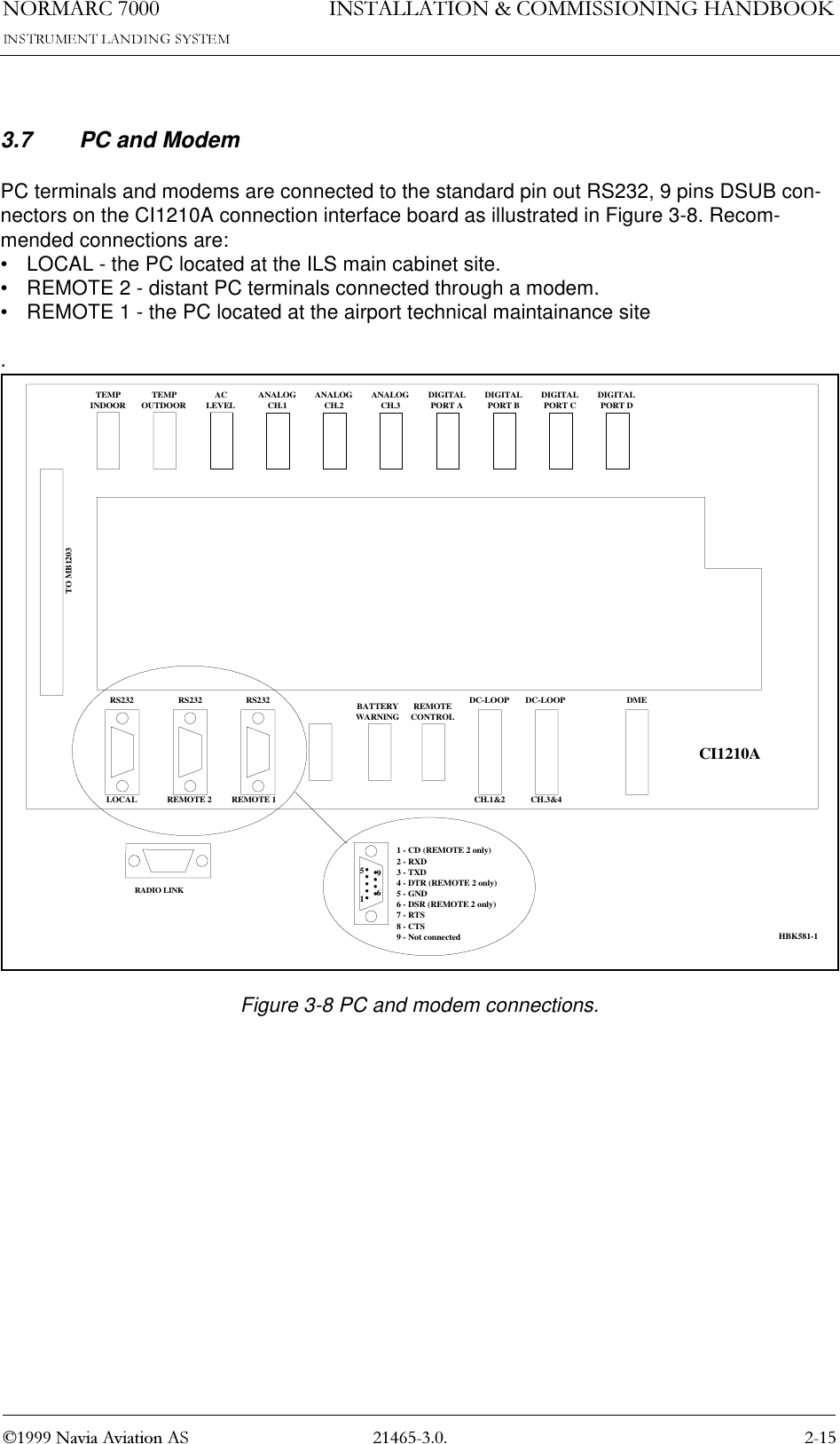
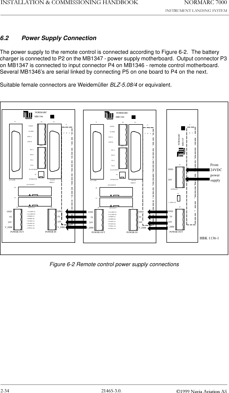
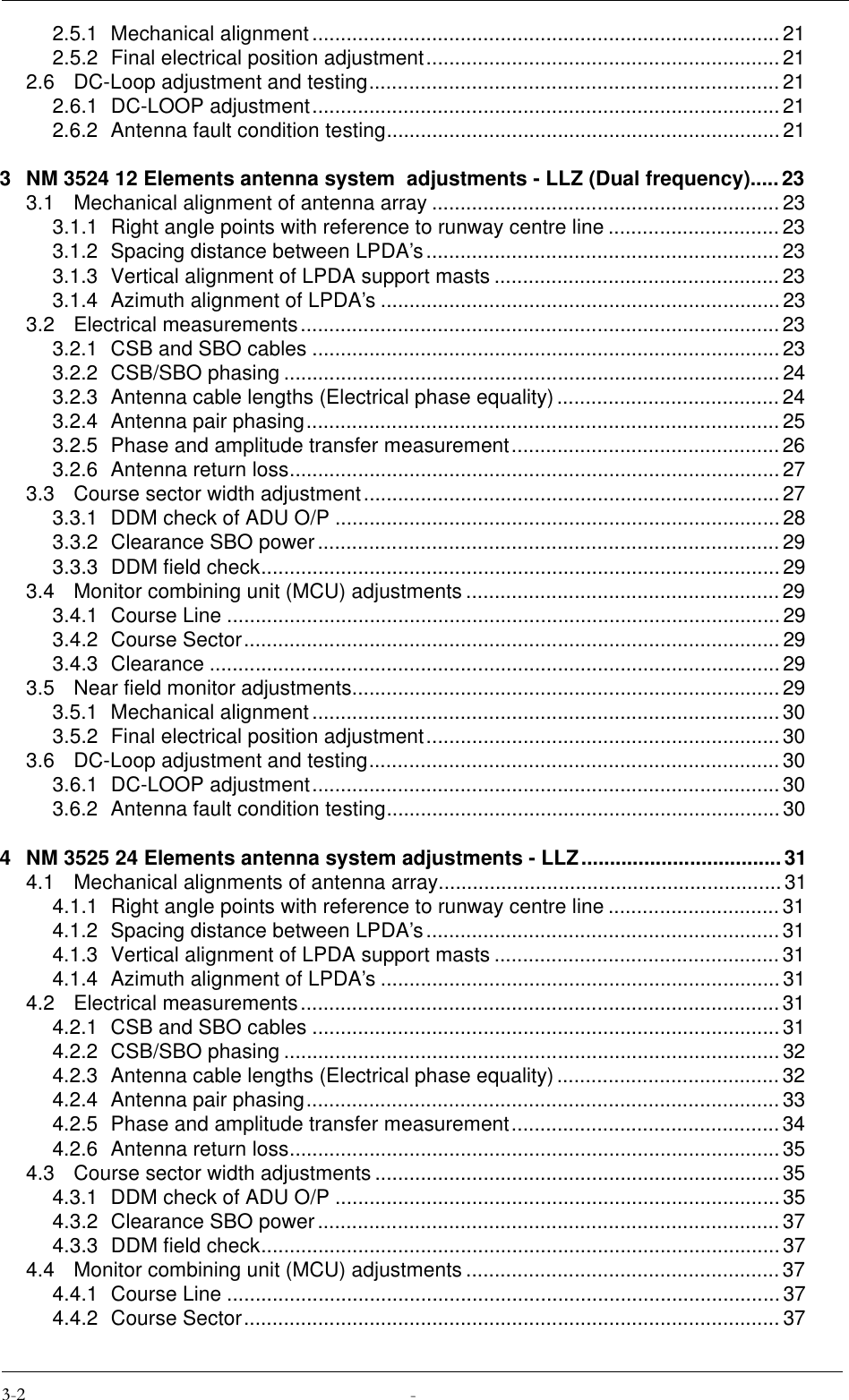
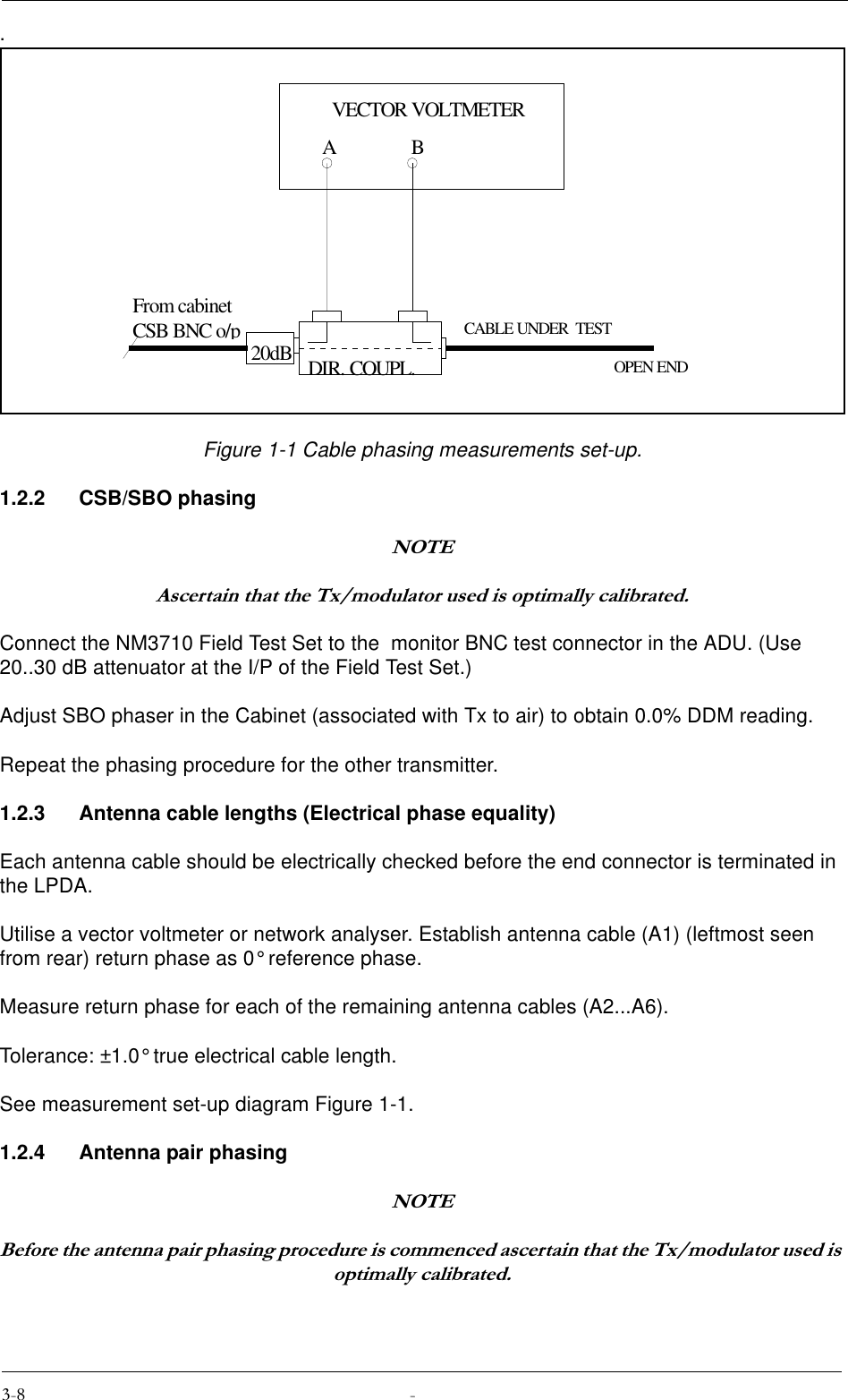
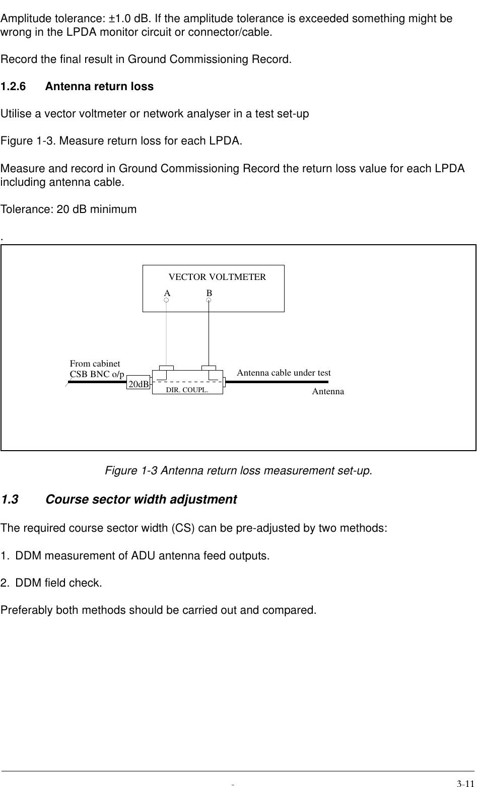
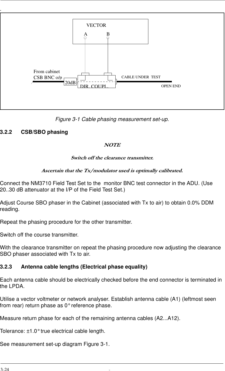
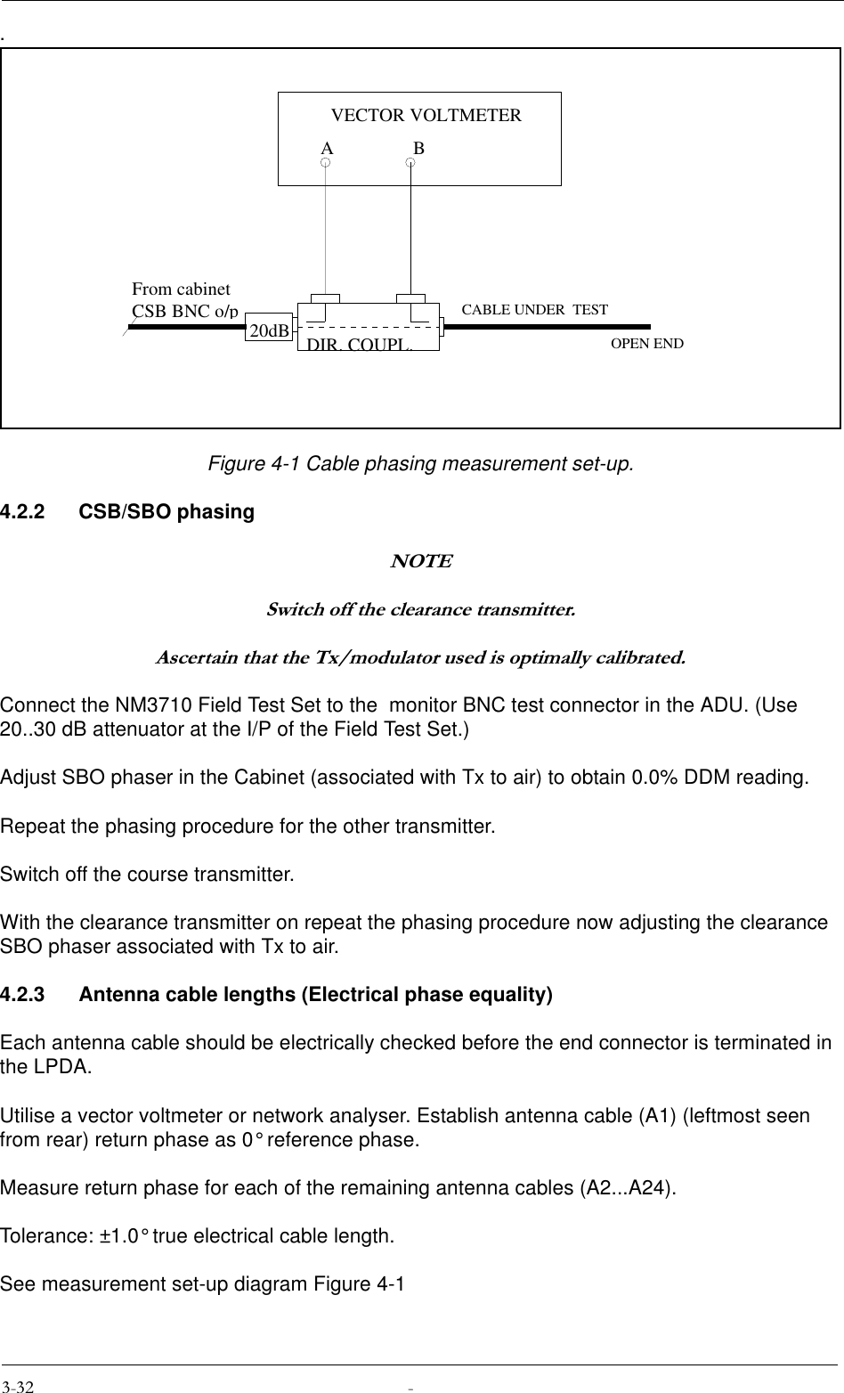
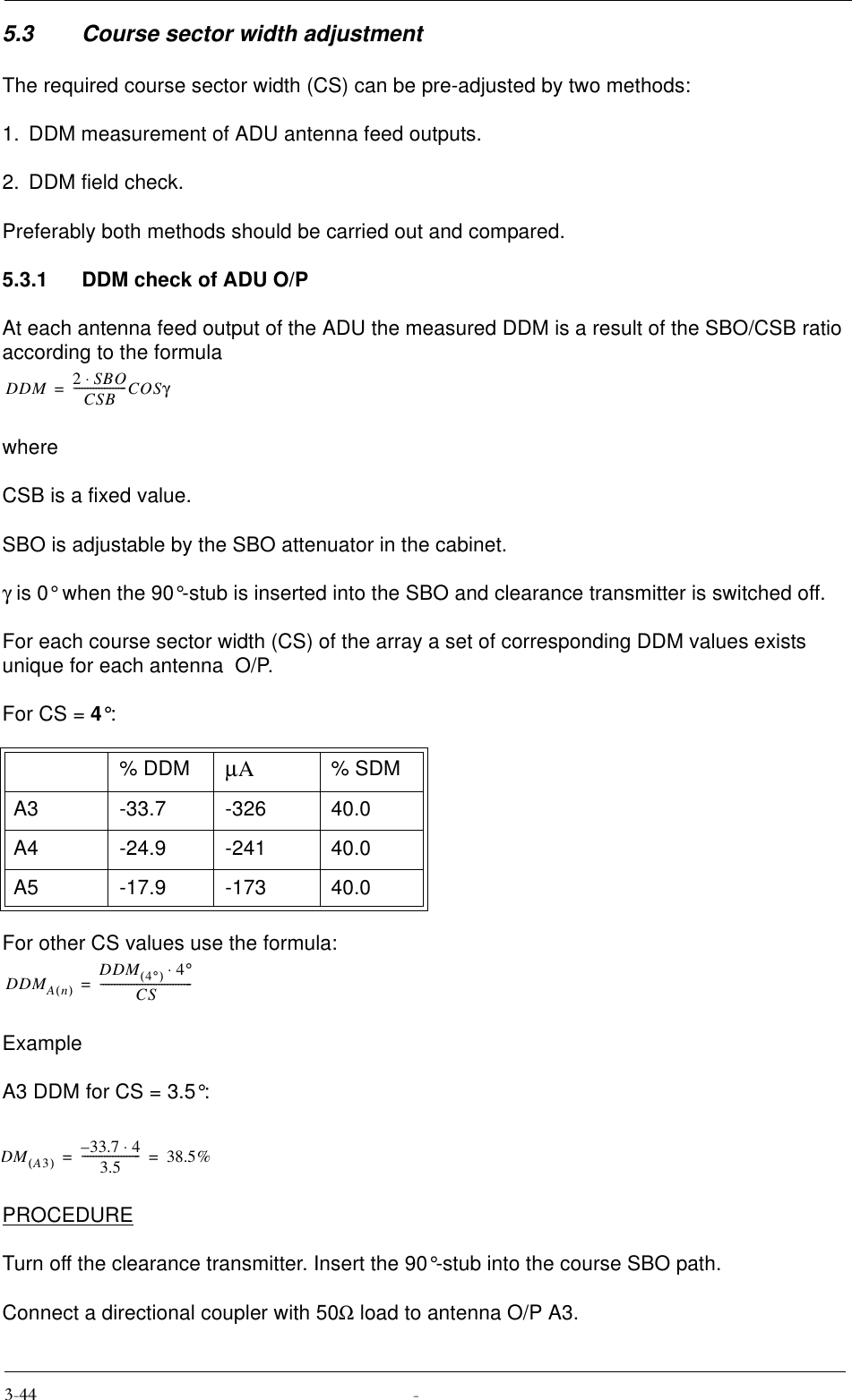
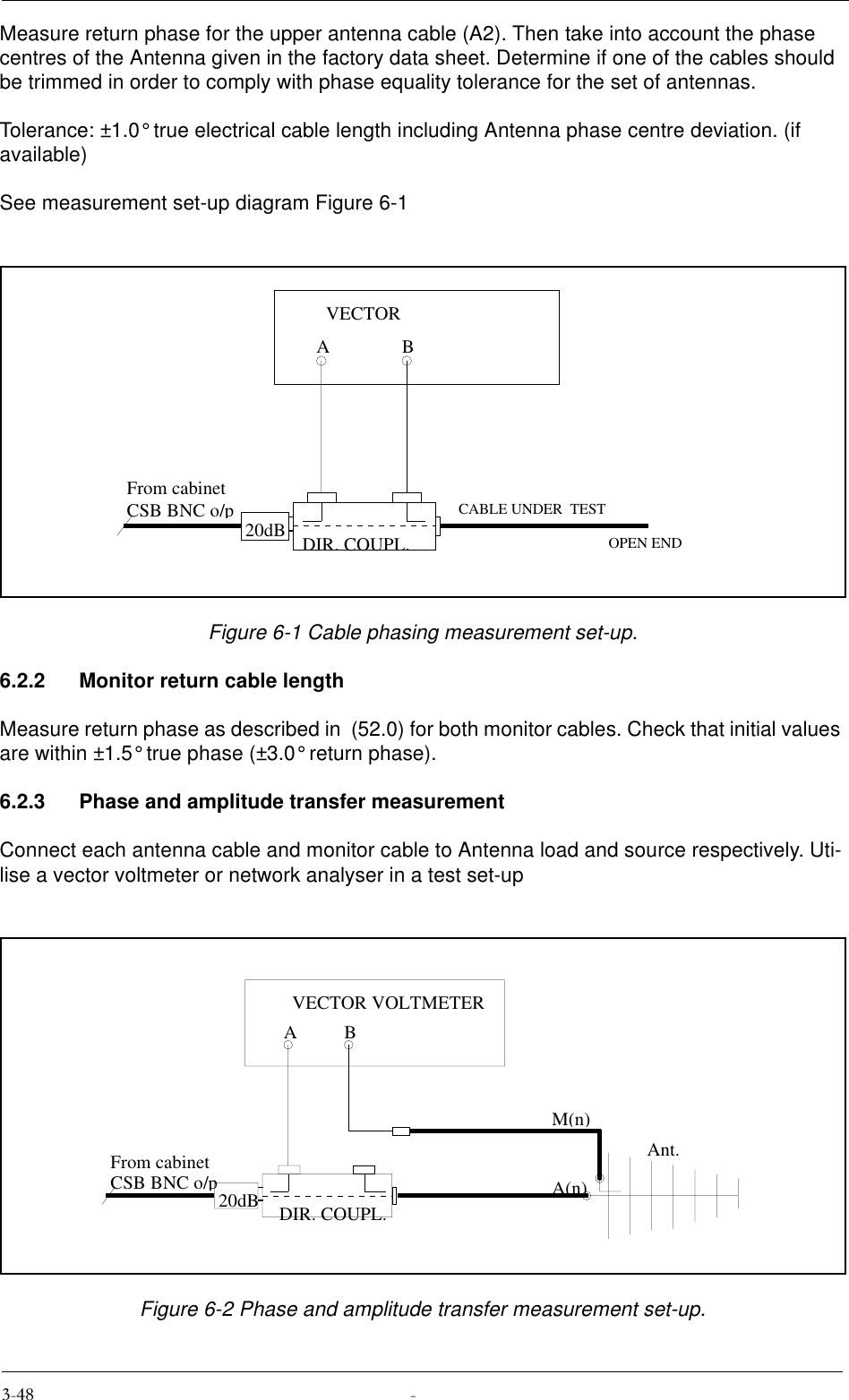
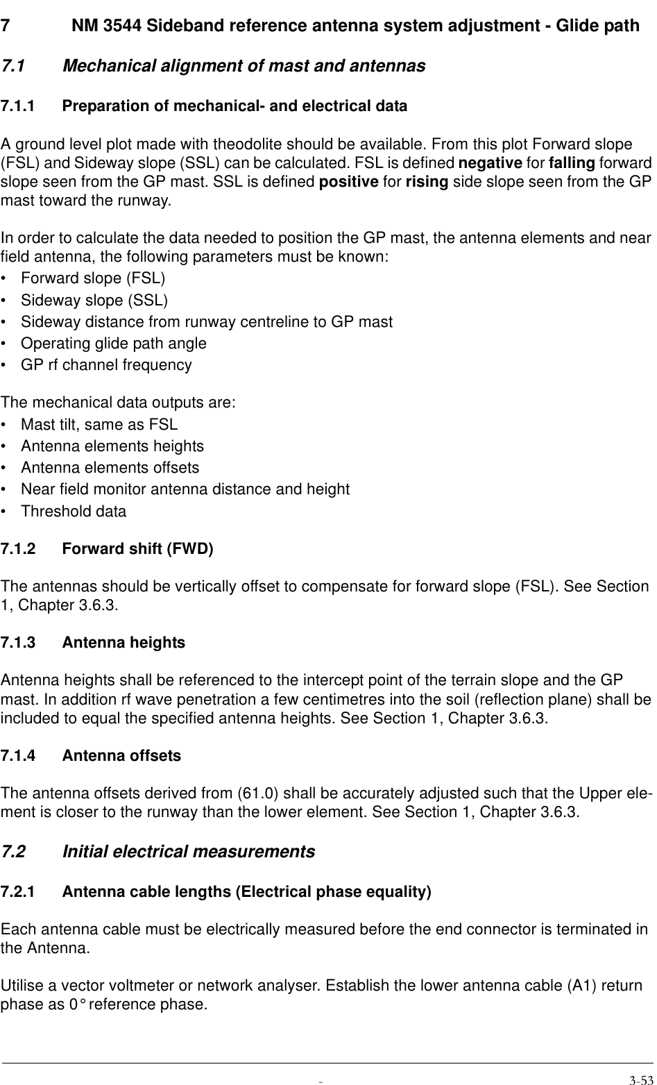
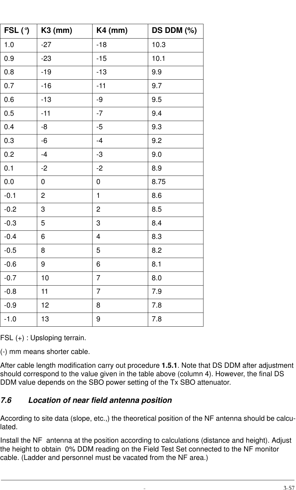
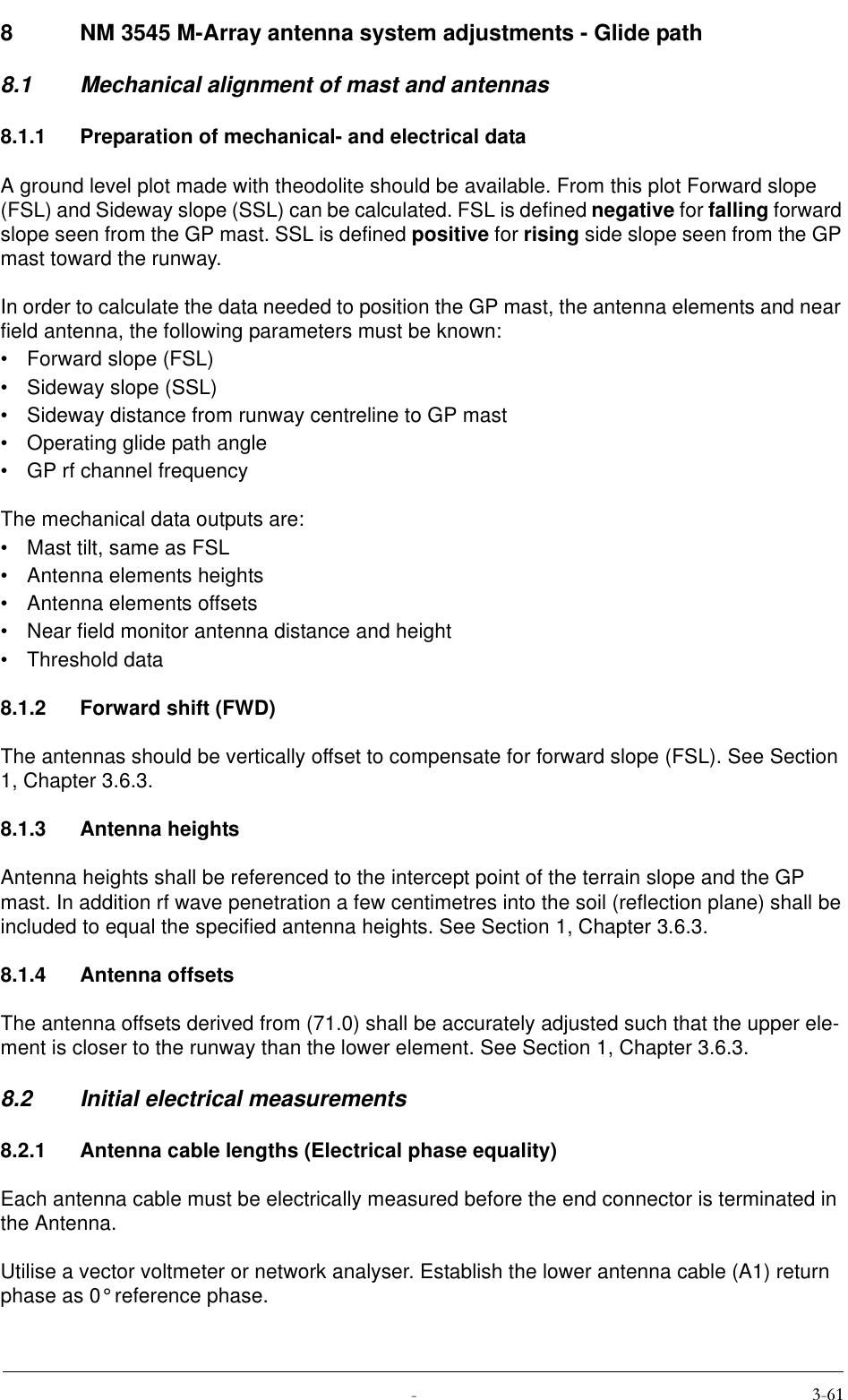
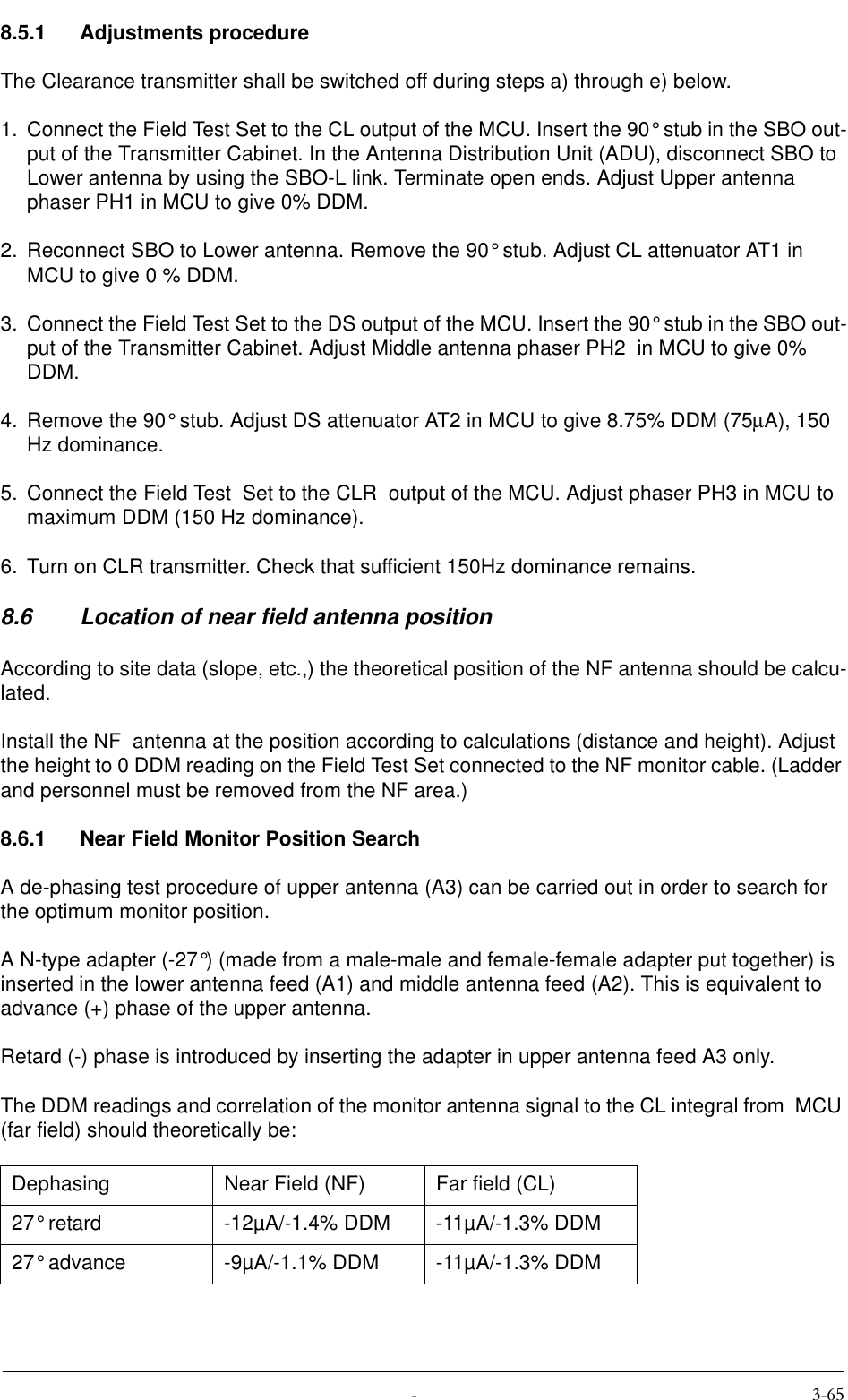
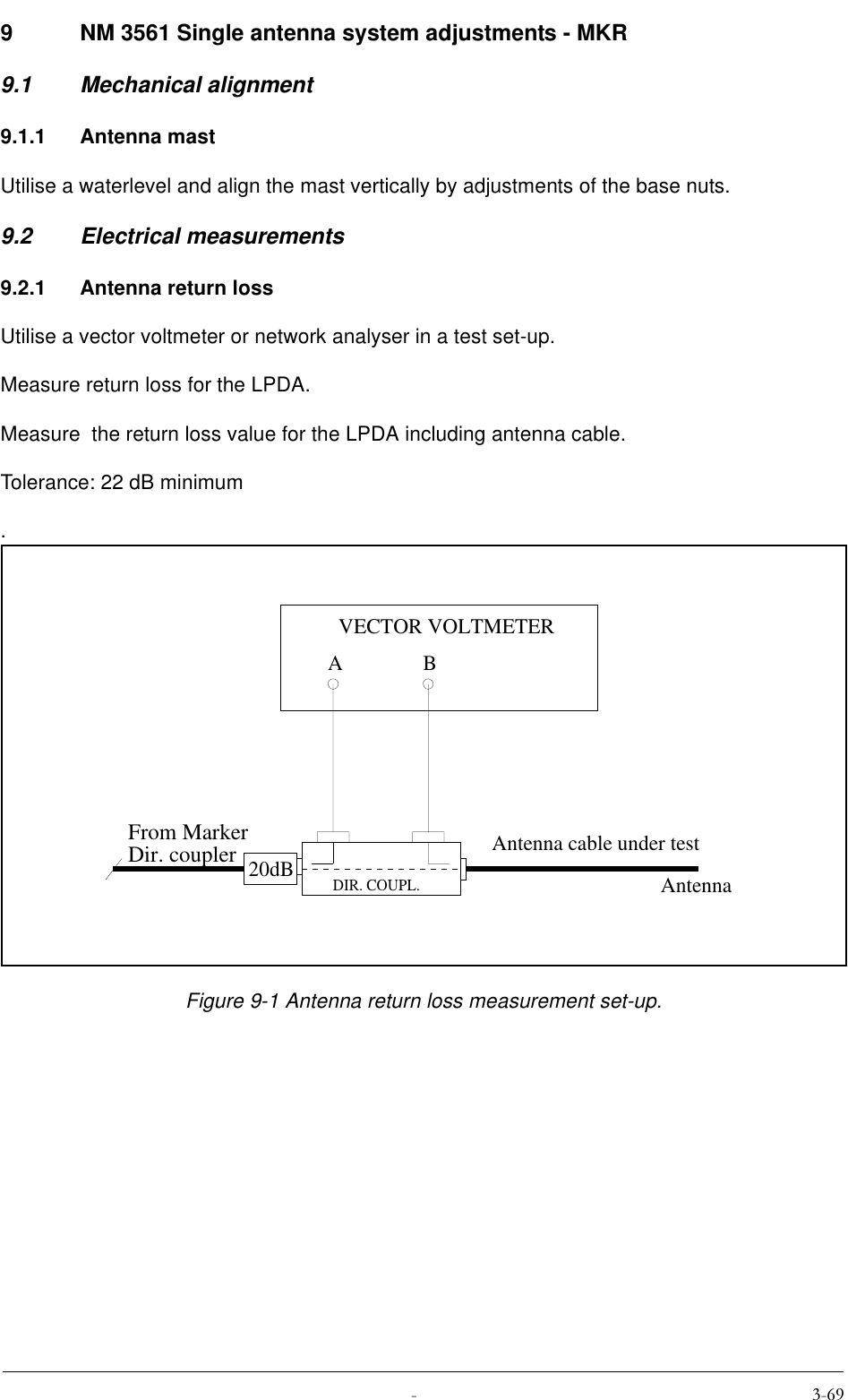
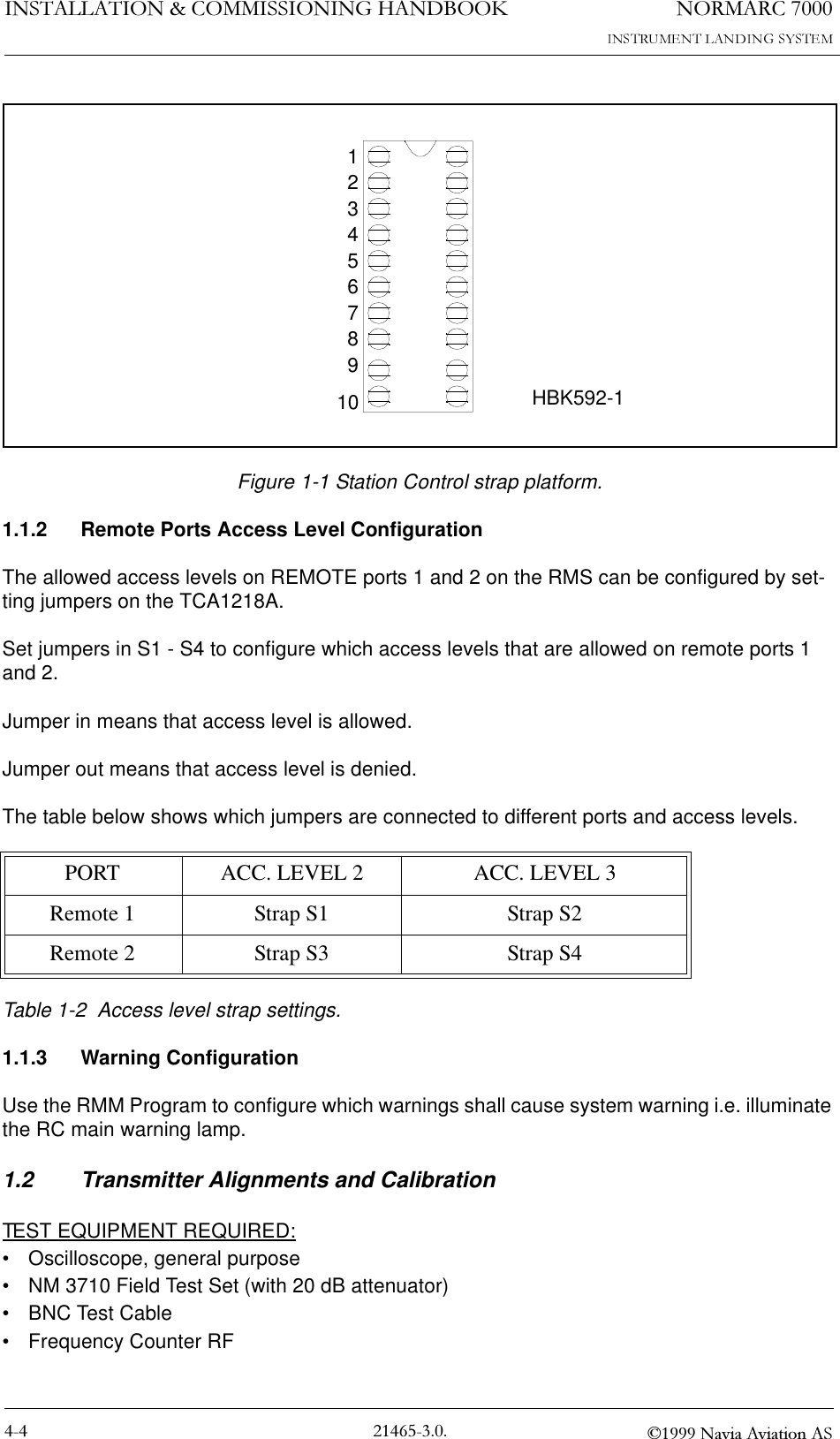
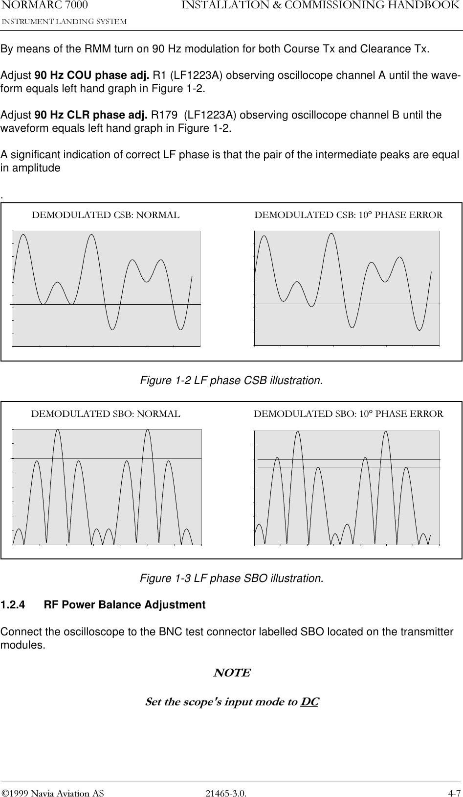
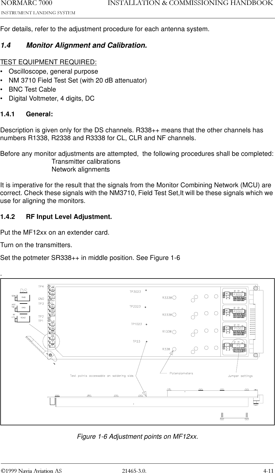
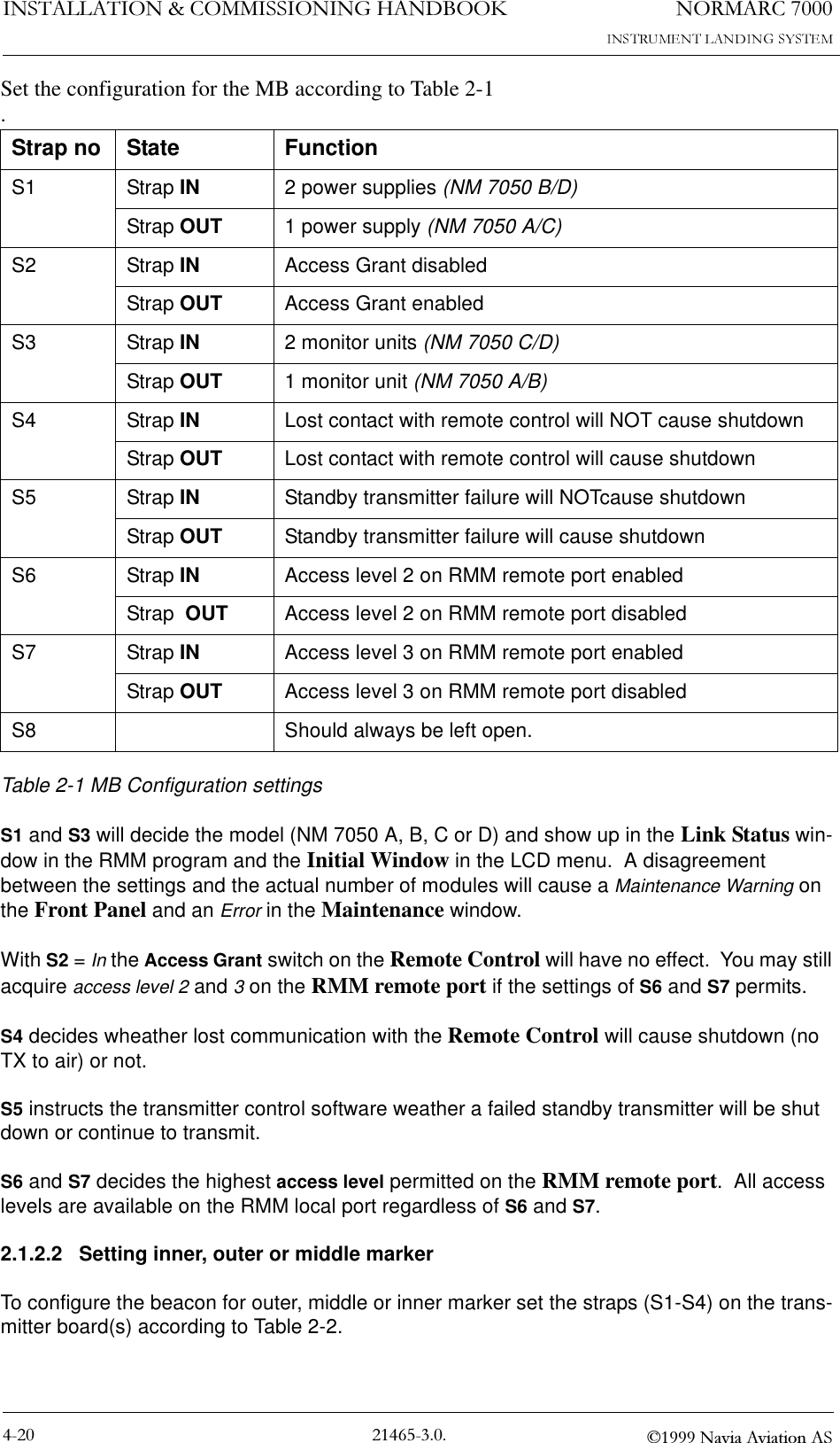
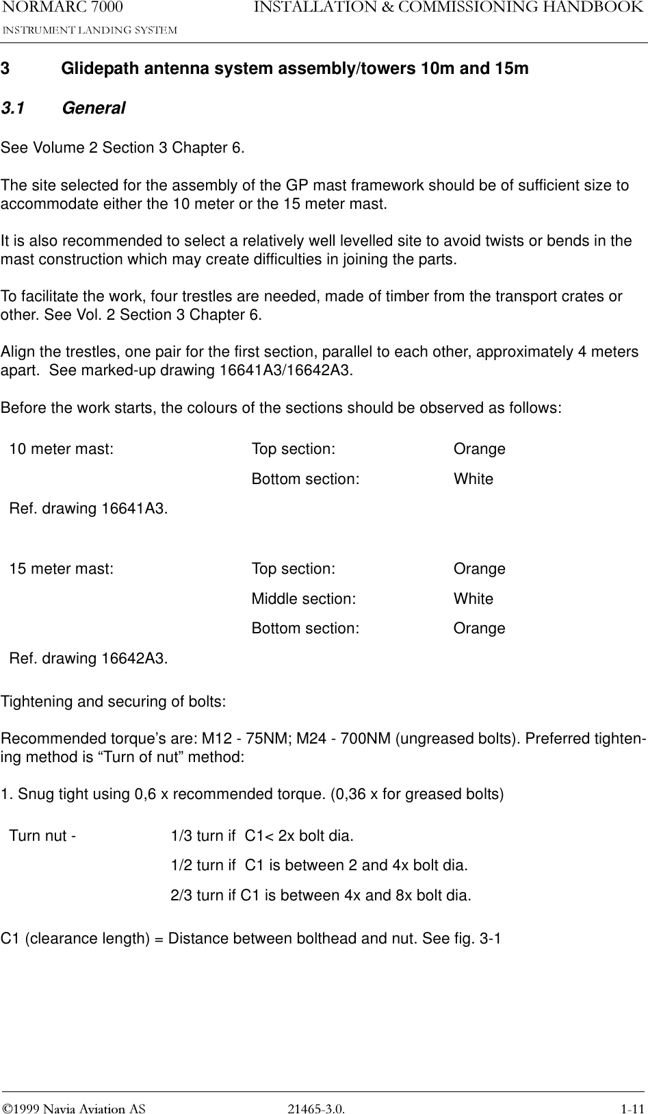
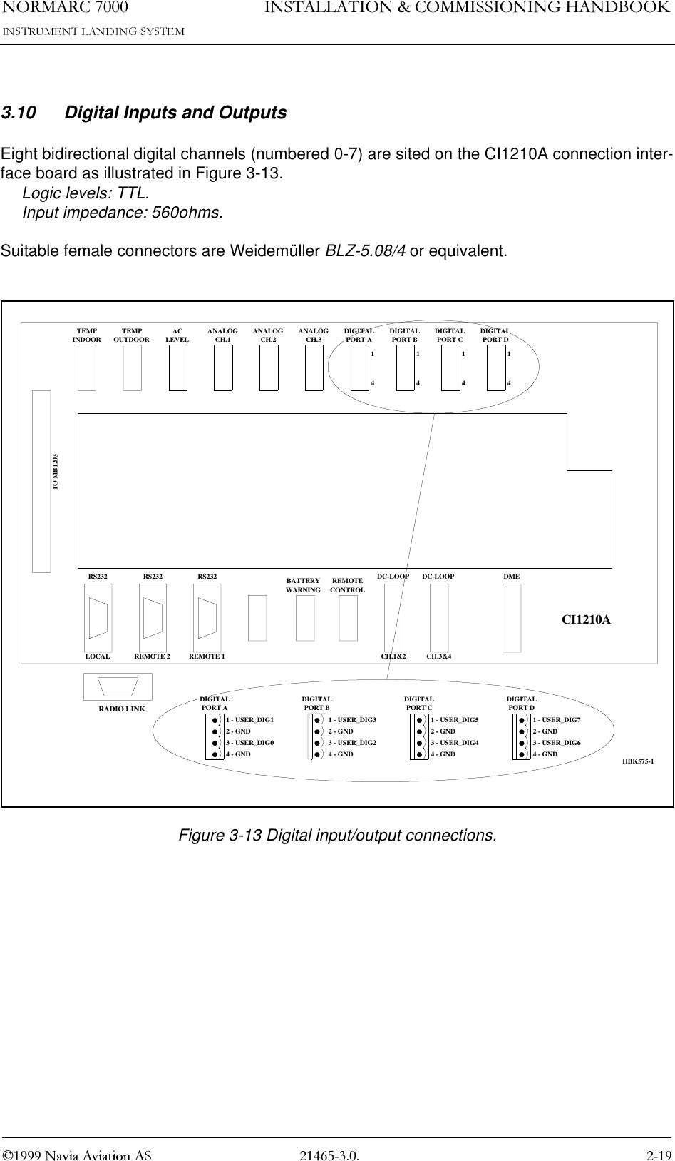
![1250$5&,167$//$7,21&200,66,21,1*+$1'%22. 1DYLD$YLDWLRQ$63.8 DME (localizer only)Distance Measurement Equipment DME is connected to the CI1210A connection interface board as illustrated in Figure 3-9.•ACT_DME[P,N] is the positive and negative terminal of the DME active signal from the DME, respectively.•IN_DME[P,N] is the positive and negative terminal of the morse code envelope signal from the DME, respectively.•OUT_DME[P,N] is the positive and negative terminal of the morse code envelope signal to the DME, respectively.A suitable female connector is Weidemüller BLZ-5.08/6 or equivalent.Figure 3-9 DME connections.TEMPINDOORTEMPOUTDOORACLEVELANALOGCH.1ANALOGCH.2ANALOGCH.3DIGITALPORT ADIGITALPORT BDIGITALPORT CDIGITALPORT DTO MB1203RS232 RS232 RS232 REMOTECONTROLDC-LOOP DC-LOOP DMELOCAL REMOTE 2 REMOTE 1 CH.1&2 CH.3&41 - ACT_DMEP2 - ACT_DMEN3 - IN_DMEP4 - IN_DMENCI1210A16S1-8DME5 - OUT_DMEP6 - OUT_DMENBATTERYWARNINGHBK582-1RADIO LINK](https://usermanual.wiki/Leidos/NORMARC7013.Normarc-7000-Instr-Landing-Sys-Installation-and-Commissioning-Handbook-Vol1/User-Guide-91127-Page-39.png)
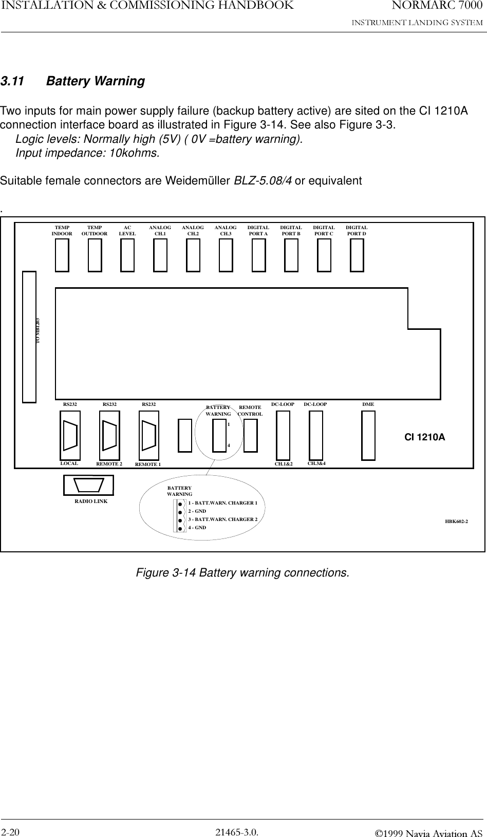

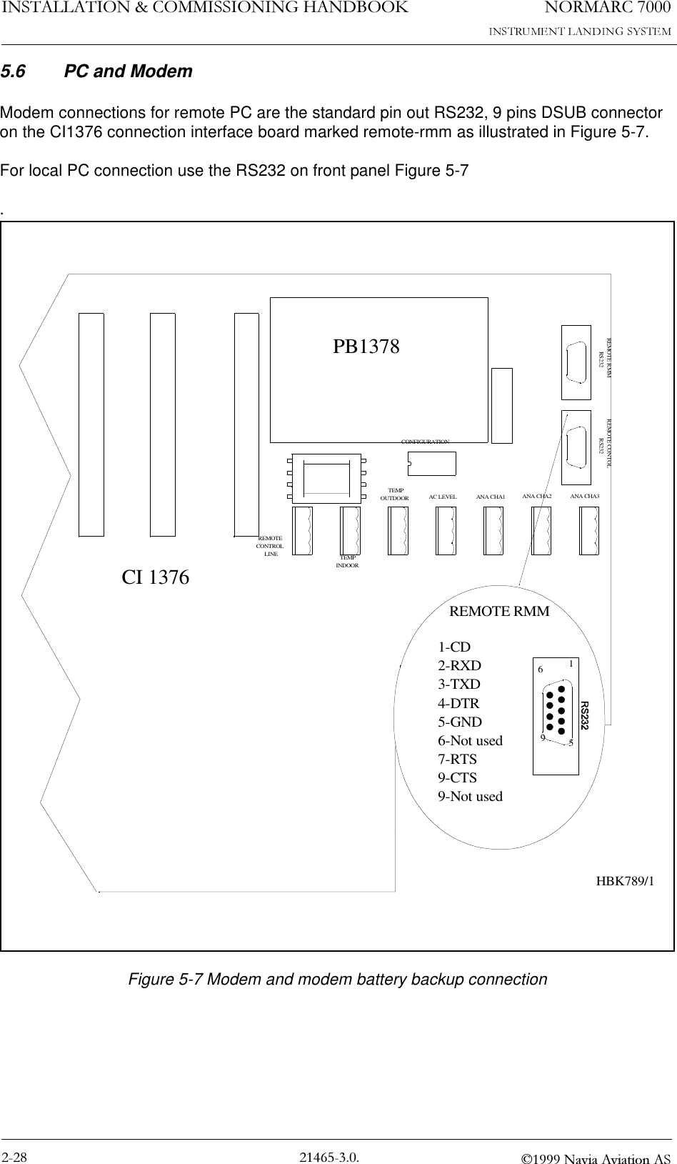
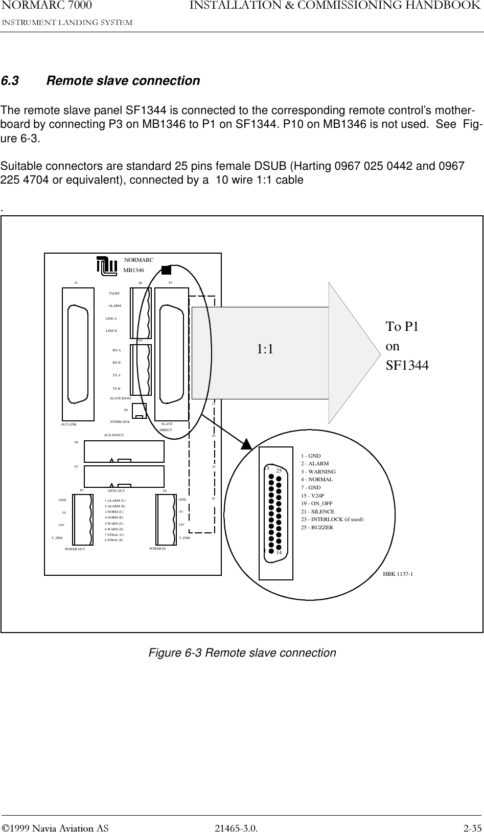
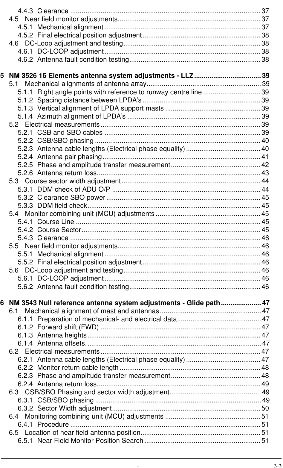
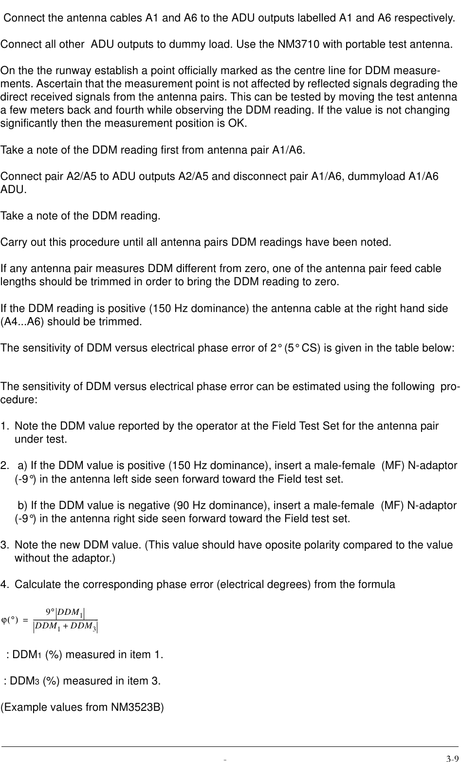
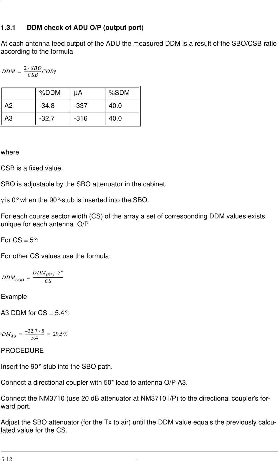
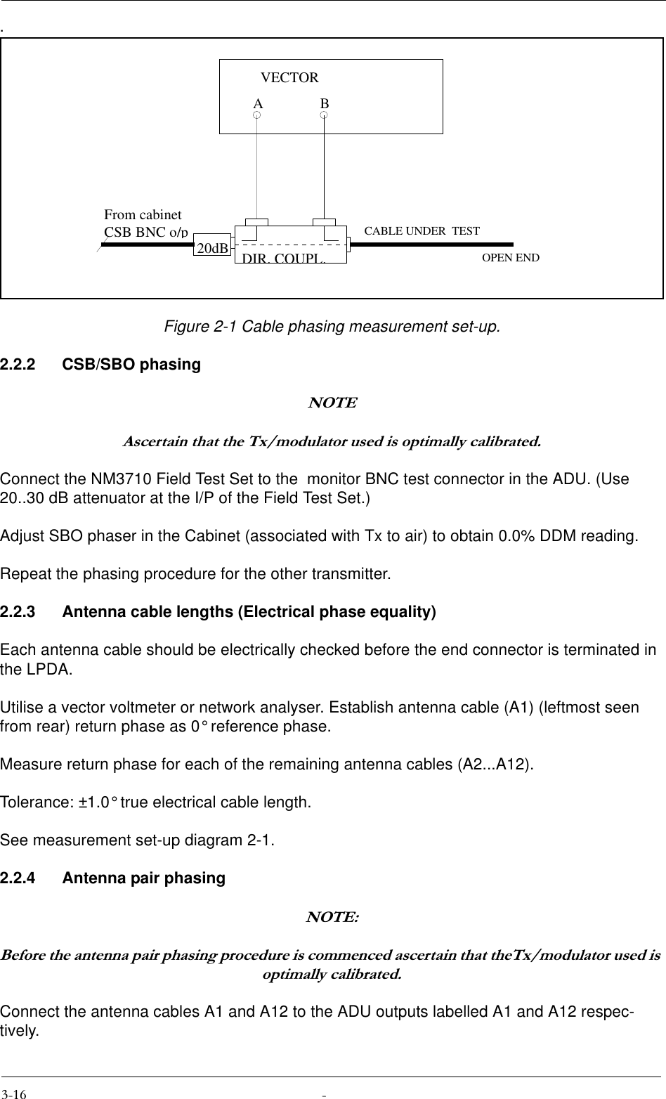
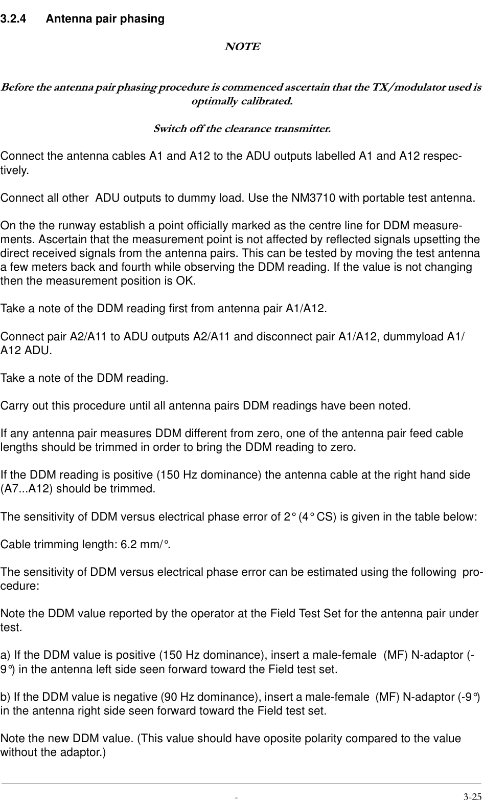
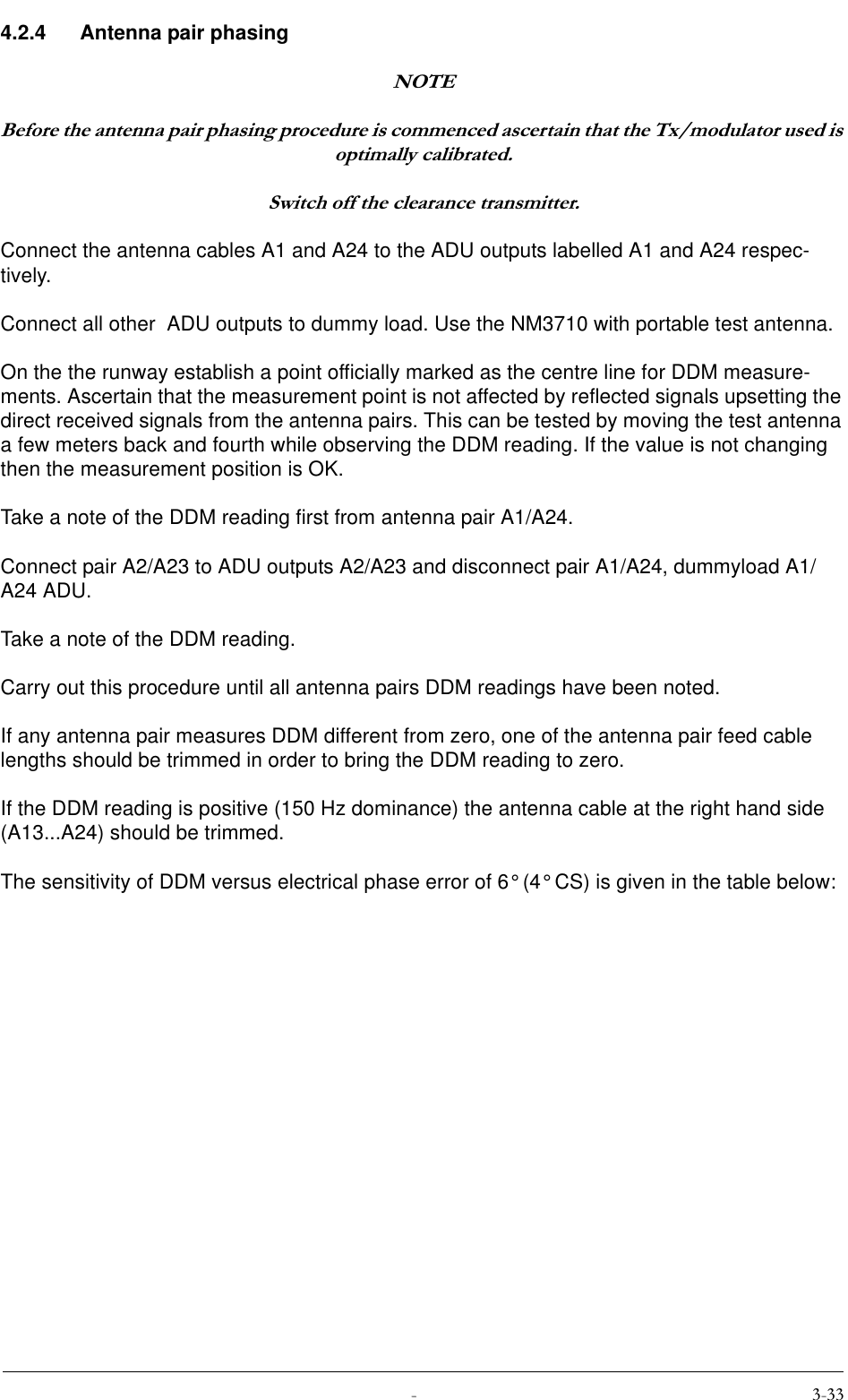
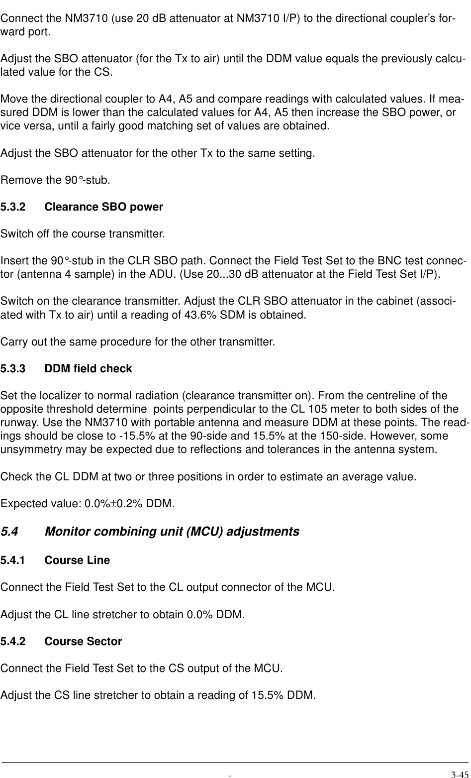
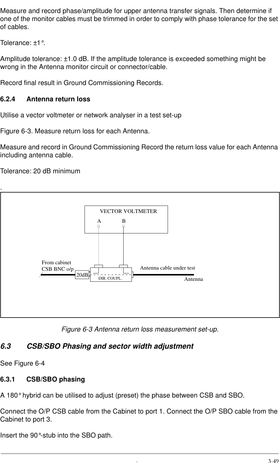
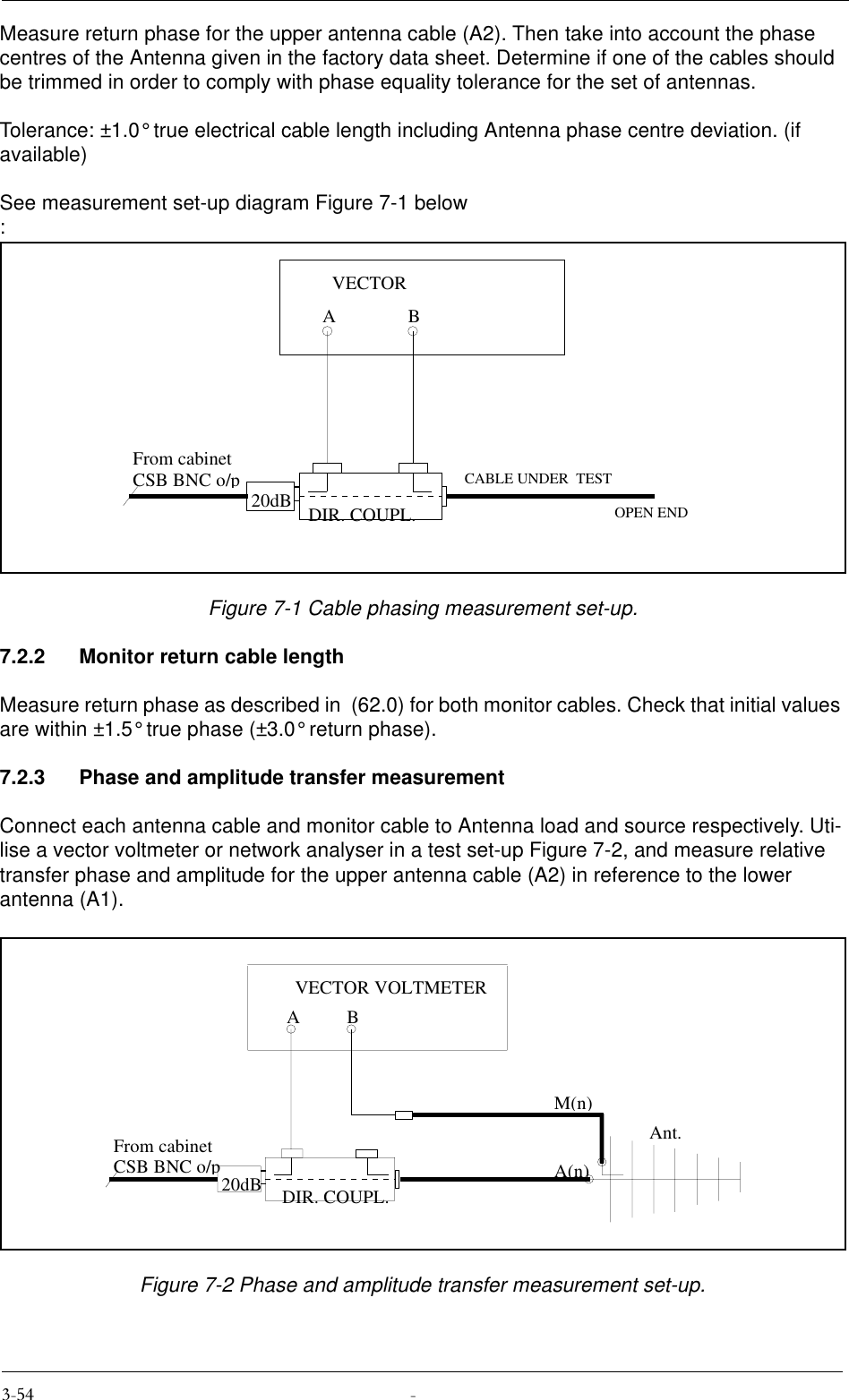
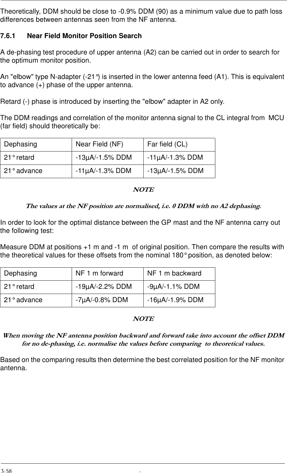
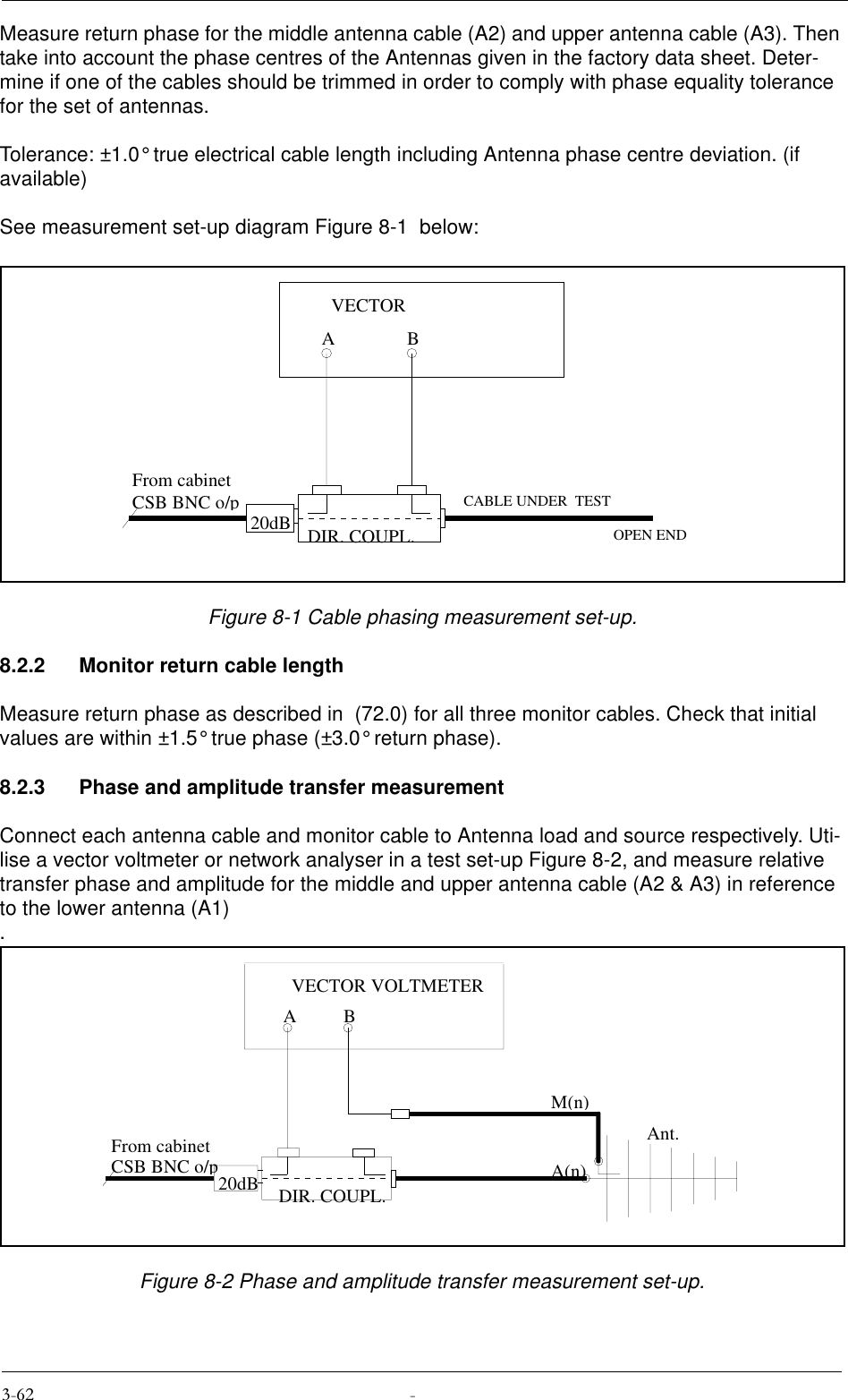
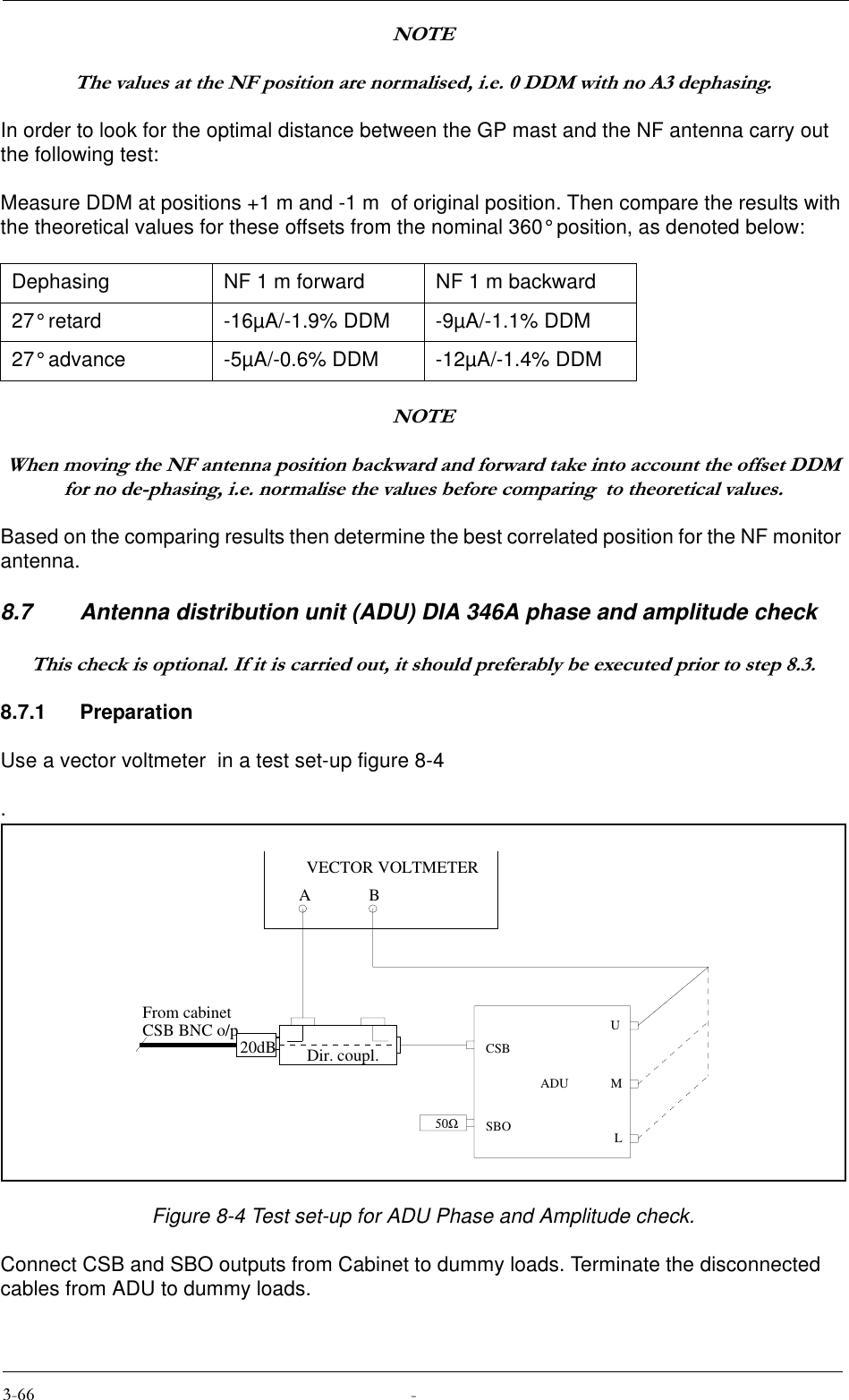
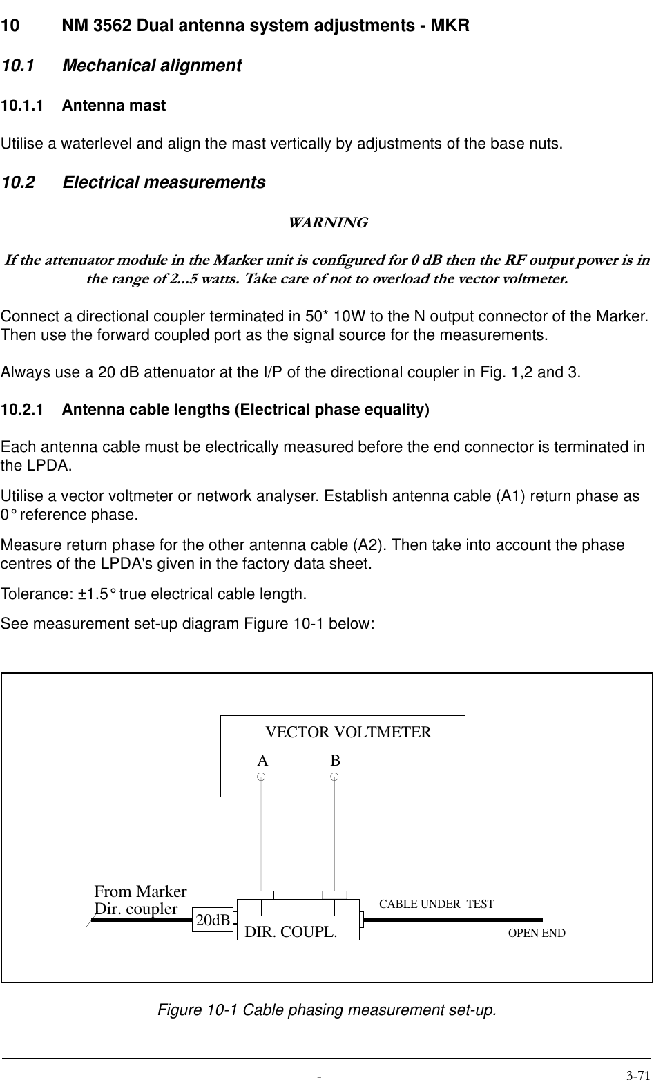
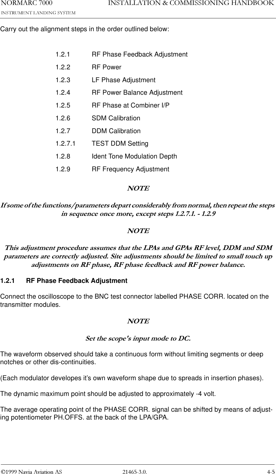
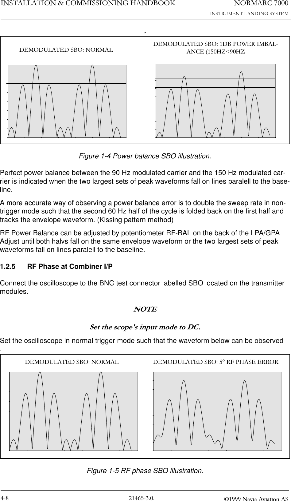
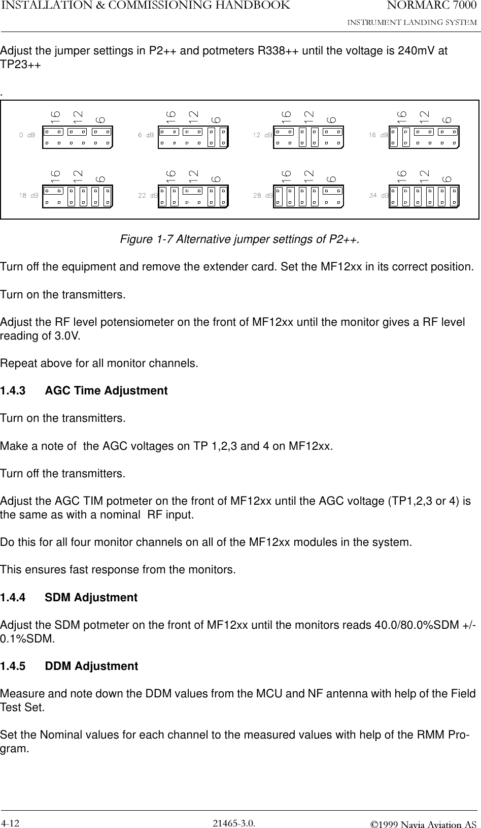
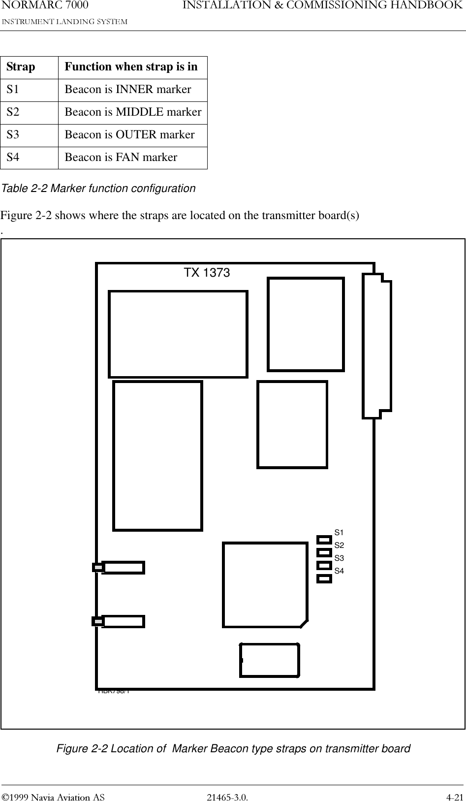
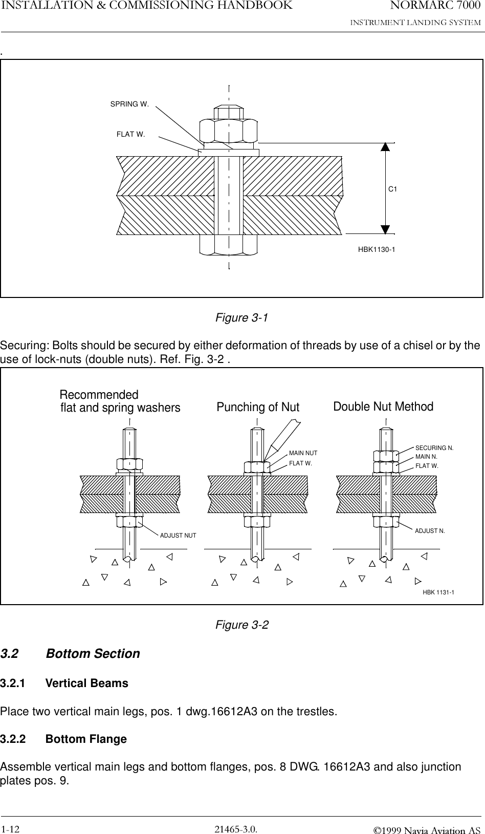
![1250$5& 1DYLD$YLDWLRQ$6,167$//$7,21&200,66,21,1*+$1'%22.5.5 Remote Control cabinetThe remote line and remote controis connected to the CI 1376 connection interface board as illustrated in Figure 5-6. • FSK_[A,B] is the modem line pair.• GND is main cabinet groundA suitable female connector for the remote line is Weidemüller BLZ-5.08/4 or equivalent.Alternatively the remote control connection is done with a RS 232 interface, standard pin out 9pins DSUB.Figure 5-6 Remote control connectionCI 1376PB 1378REMOTECONTROLLINETEMPOUTDOORTEMPINDOORAC LEVEL ANA CHA1 ANA CHA2 ANA CHA3REMOTE RMMRS232REMOTE CONTOLRS232CONFIGURATION1 - GND2 - RC_LINE B4 - Not used1 - Not used3 - RXD2 - TXD4 - Not used5 - GND6 - Not used7 - Not used8 - Not used9 - Not usedREMOTECONTROLREMOTECONTROLLINERS-232HBK788/32 - RC_LINE A](https://usermanual.wiki/Leidos/NORMARC7013.Normarc-7000-Instr-Landing-Sys-Installation-and-Commissioning-Handbook-Vol1/User-Guide-91127-Page-50.png)