Leidos NORMARC7031 User Manual Normarc 7050 General Description
Lockheed Martin Air Traffic Management Normarc 7050 General Description
UserManual.wiki
>
Leidos
>
NORMARC7031 User Manual
>
7031 General Description
Contents
1.
7031 Installation Manual Cover
2.
7031 Installation and Communication Manual Vol1
3.
7031 Installation and Communication Manual Vol2
4.
7031 General Description
5.
7031 User Manual
7031 General Description
Navigation menu
Upload a User Manual
Namespaces
Wiki Guide
HTML
PDF
Info
Views
User Manual
Discussion / Help
Navigation
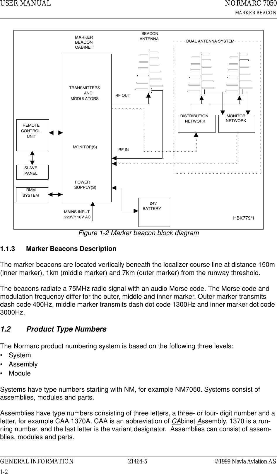
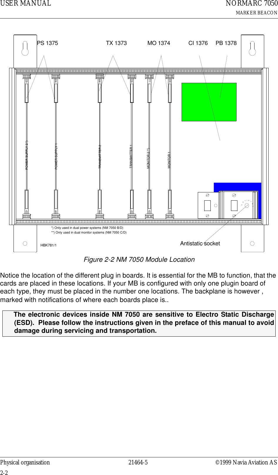
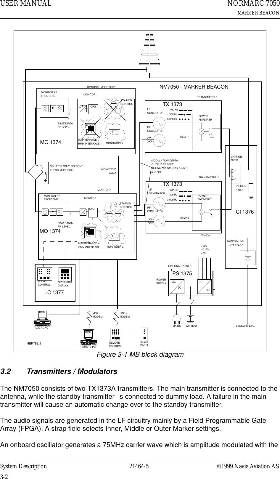
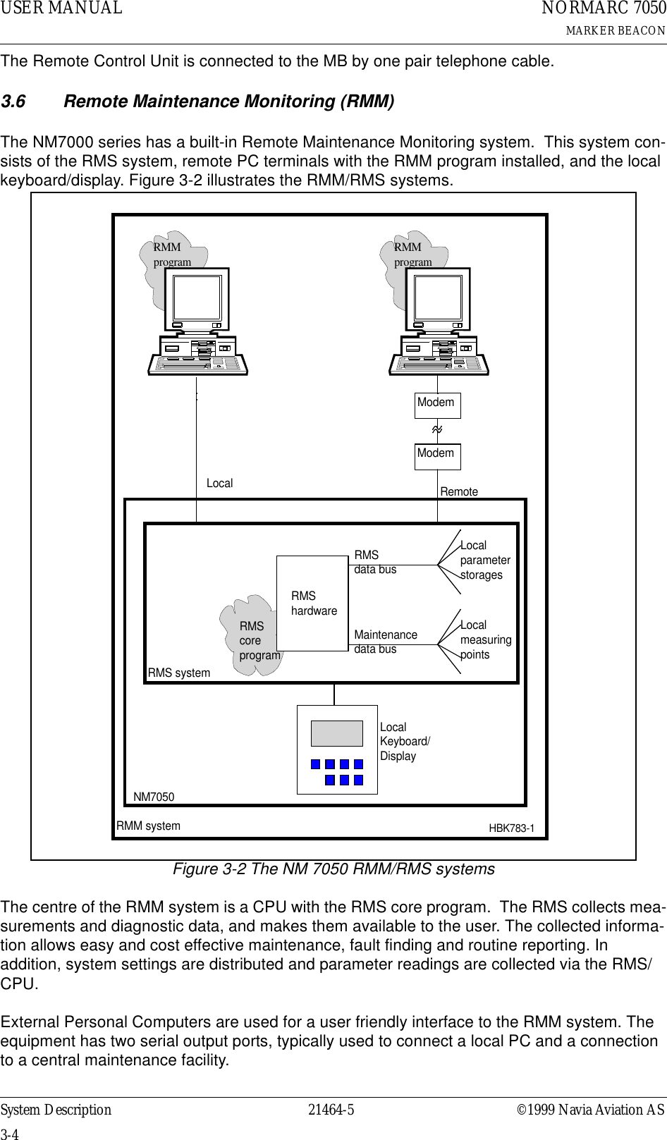
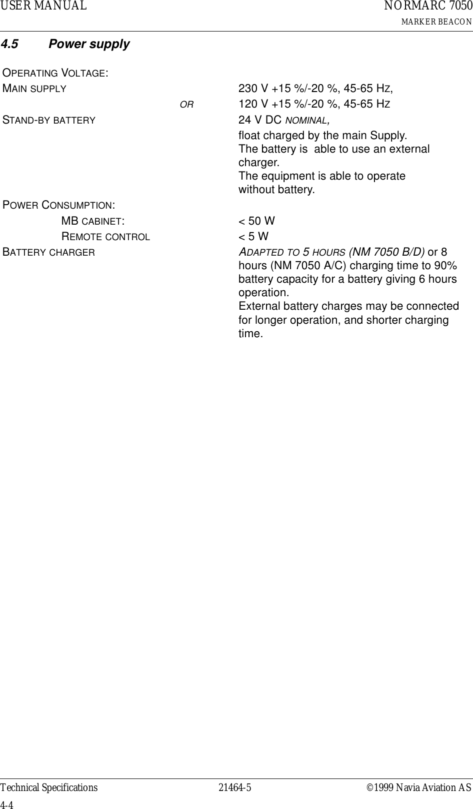
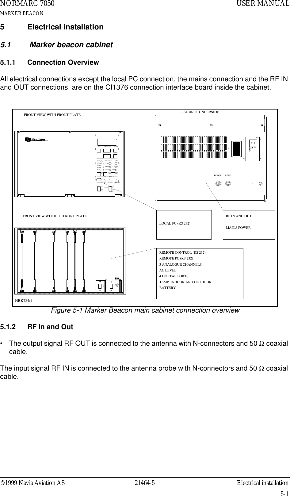
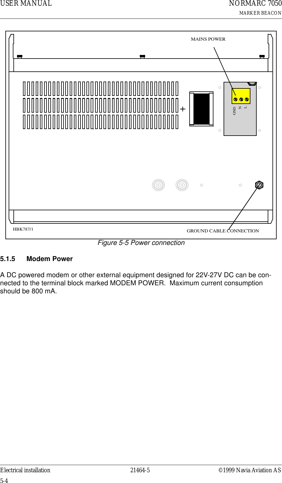
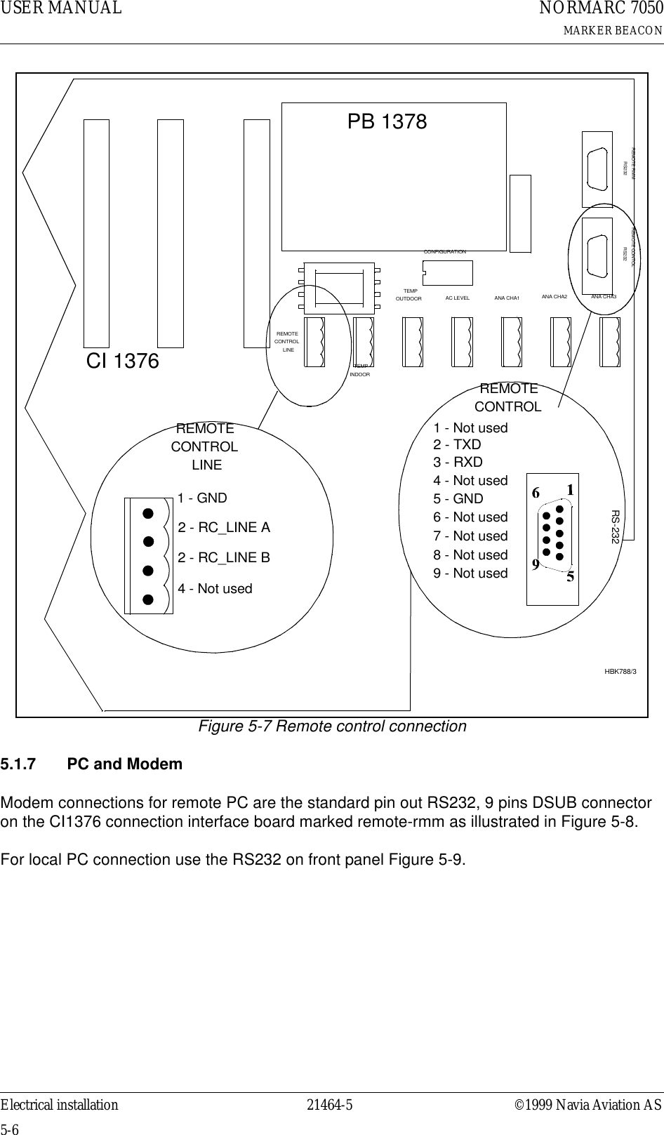
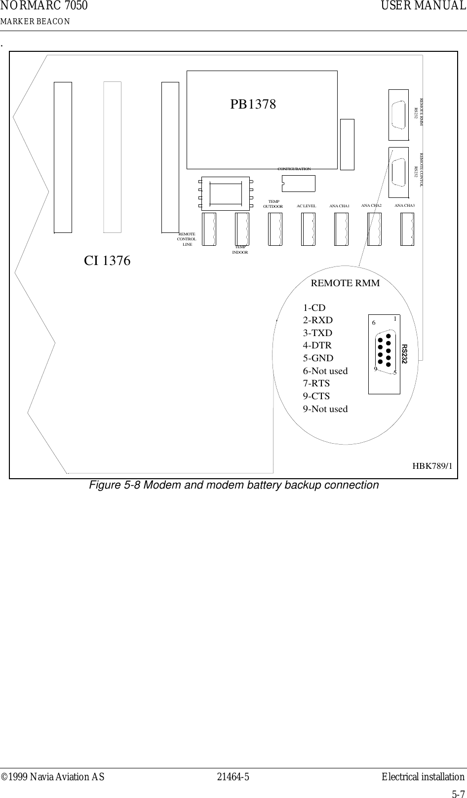
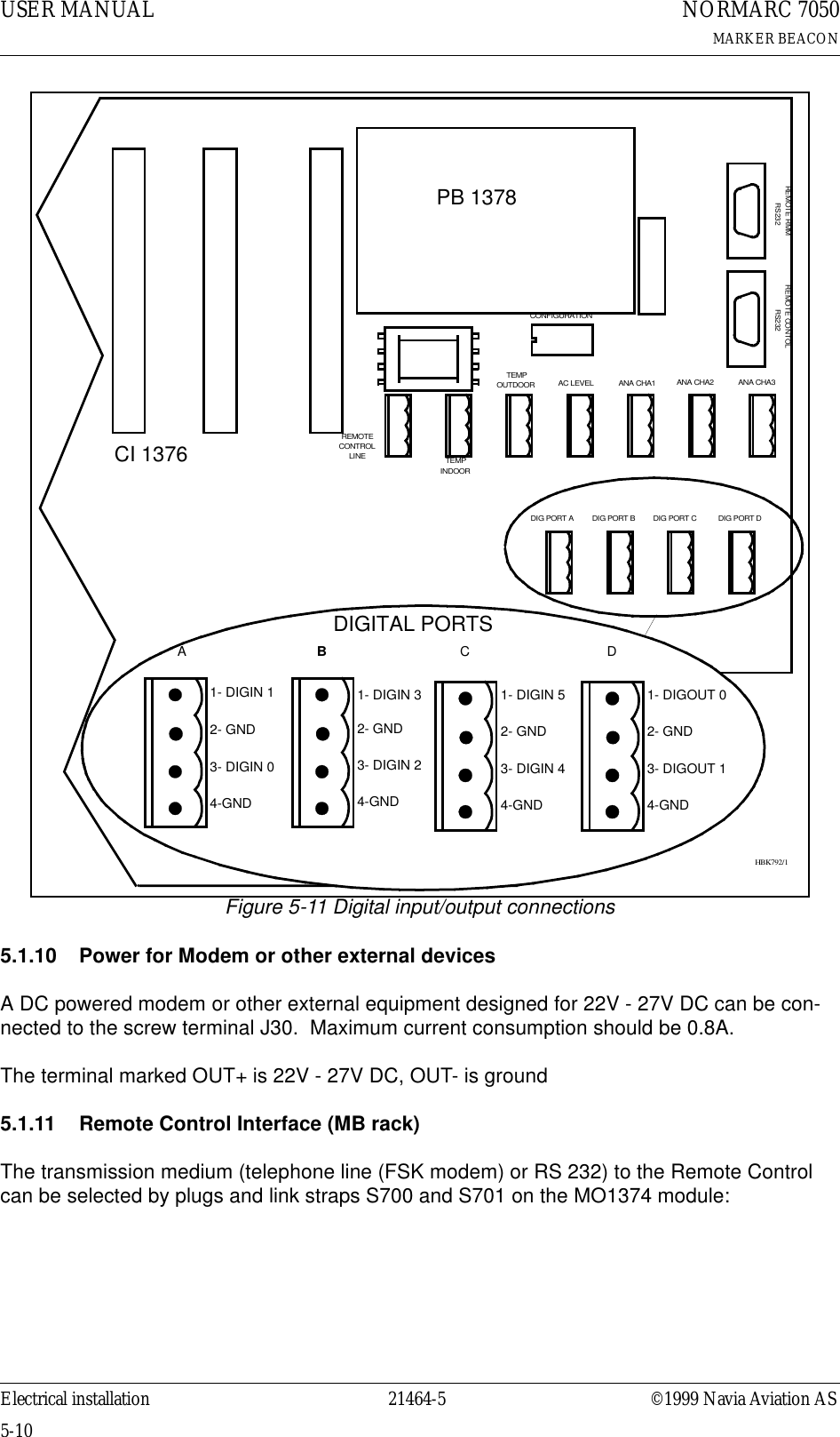
![©1999 Navia Aviation AS 21464-5 Electrical installationUSER MANUALNORMARC 7050MARKER BEACON5-5Figure 5-6 Modem Power5.1.6 Remote ControlThe remote line and remote control is connected to the CI 1376 connection interface board as illustrated in Figure 5-7. • FSK_[A,B] is the modem line pair.• GND is main cabinet groundA suitable female connector for the remote line is Weidemüller BLZ-5.08/4 or equivalent.Alternatively the remote control connection is done with a RS 232 interface. The mode is con-figured on MO 1374, refer to 7.2.3.Note: The position of RXD and TXD is interchanged from the normal RS-232 layout in the Remote Control connector. Therefore a special cable must be used for connection to external equipment.CI 1376REMOTECONTROLLINETEMPOUTDOORTEMPINDOORAC LEVEL ANA CHA1 ANA CHA2 ANA CHA3DIG PORT A DIG PORT B DIG PORT C DIG PORT D-(GND)123BATT GNDEXT CHARGEBATT +24VBATTERY- ++ (+24V DC)MODEM POWERMODEM POWERH1116/1](https://usermanual.wiki/Leidos/NORMARC7031.7031-General-Description/User-Guide-103314-Page-23.png)