Leidos NORMARC7031 User Manual 7050
Lockheed Martin Air Traffic Management 7050
UserManual.wiki
>
Leidos
>
NORMARC7031 User Manual
>
7031 User Manual
Contents
1.
7031 Installation Manual Cover
2.
7031 Installation and Communication Manual Vol1
3.
7031 Installation and Communication Manual Vol2
4.
7031 General Description
5.
7031 User Manual
7031 User Manual
Navigation menu
Upload a User Manual
Namespaces
Wiki Guide
HTML
PDF
Info
Views
User Manual
Discussion / Help
Navigation
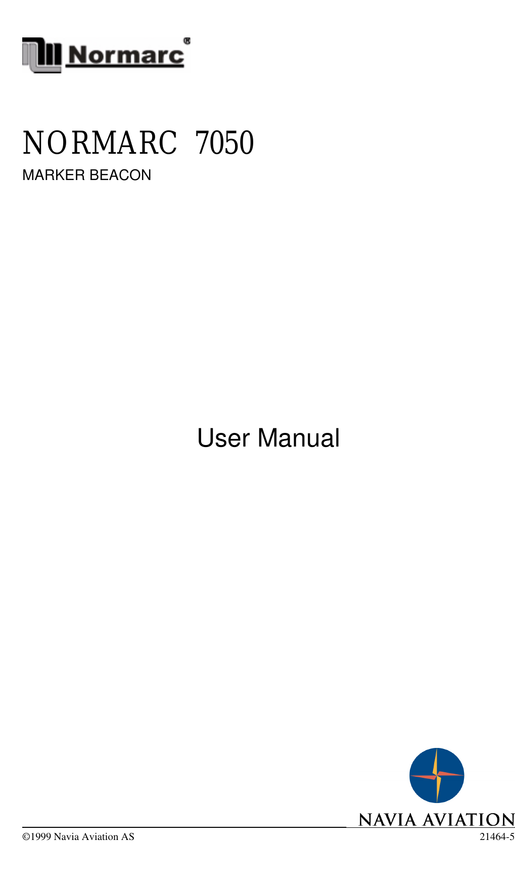

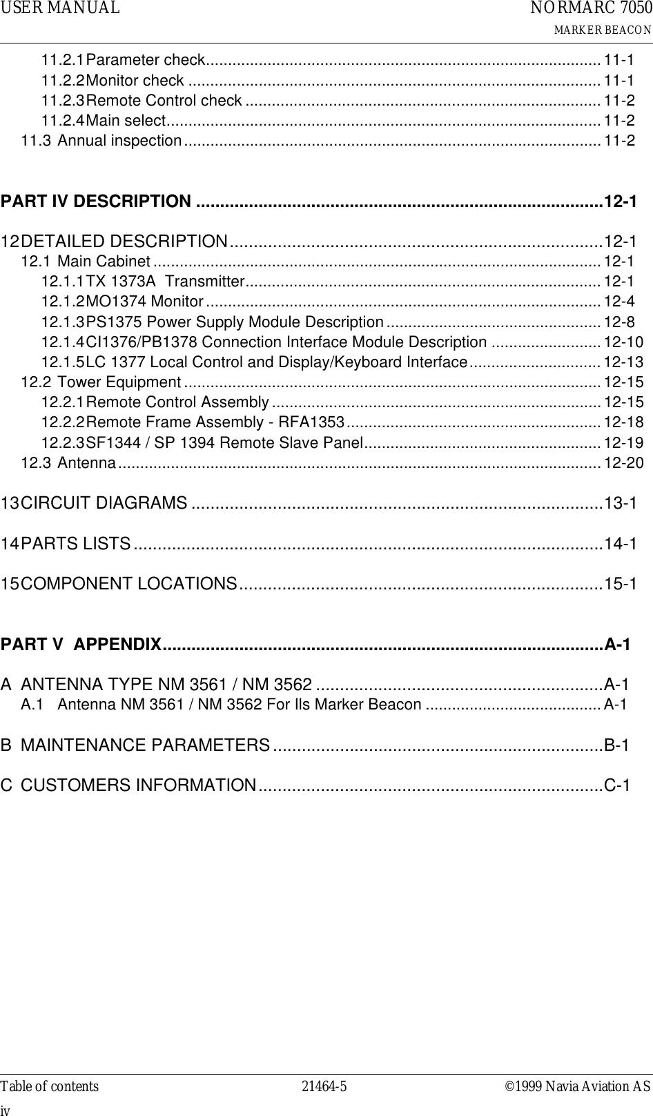
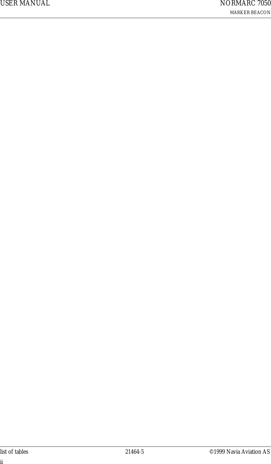
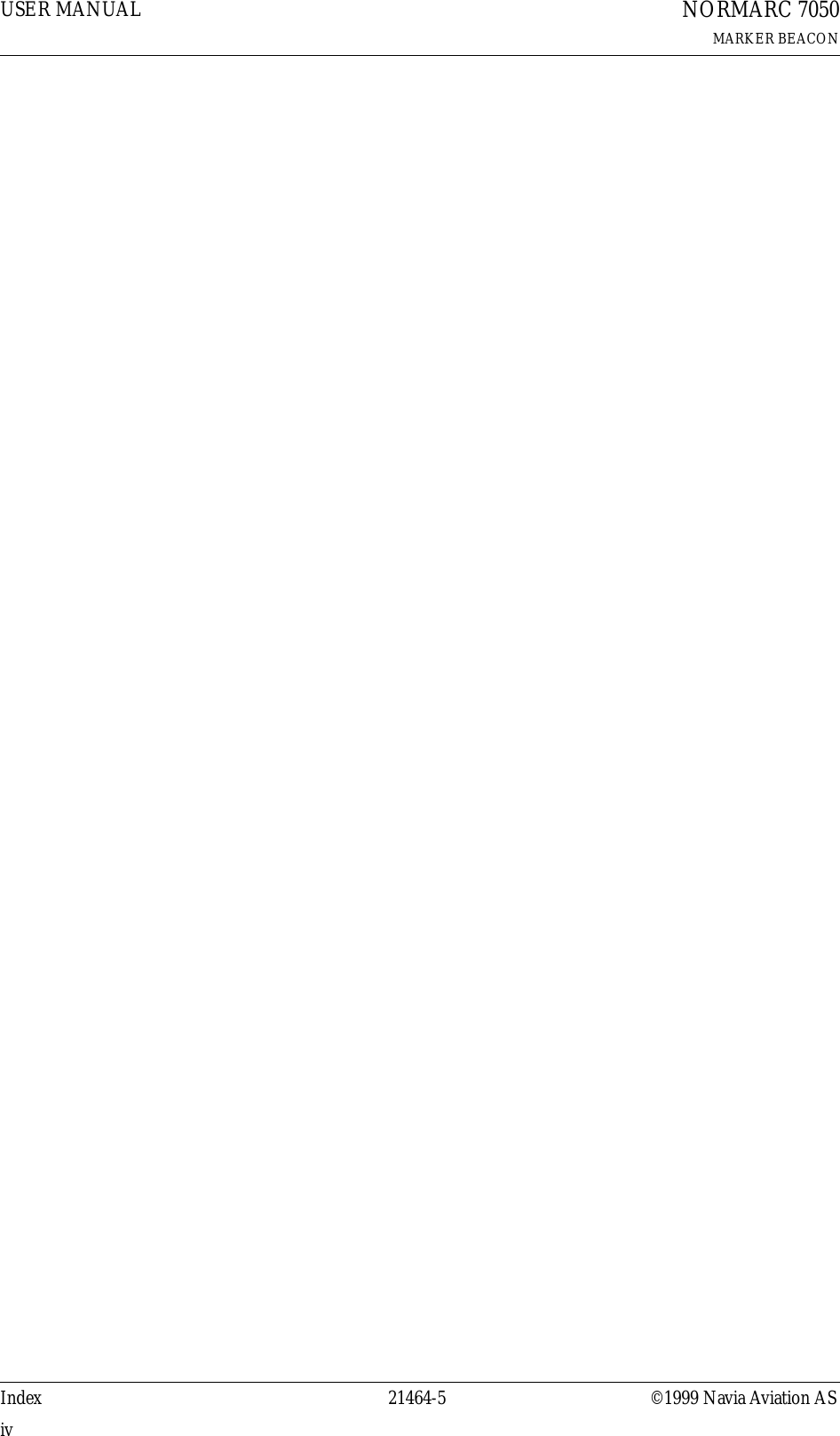
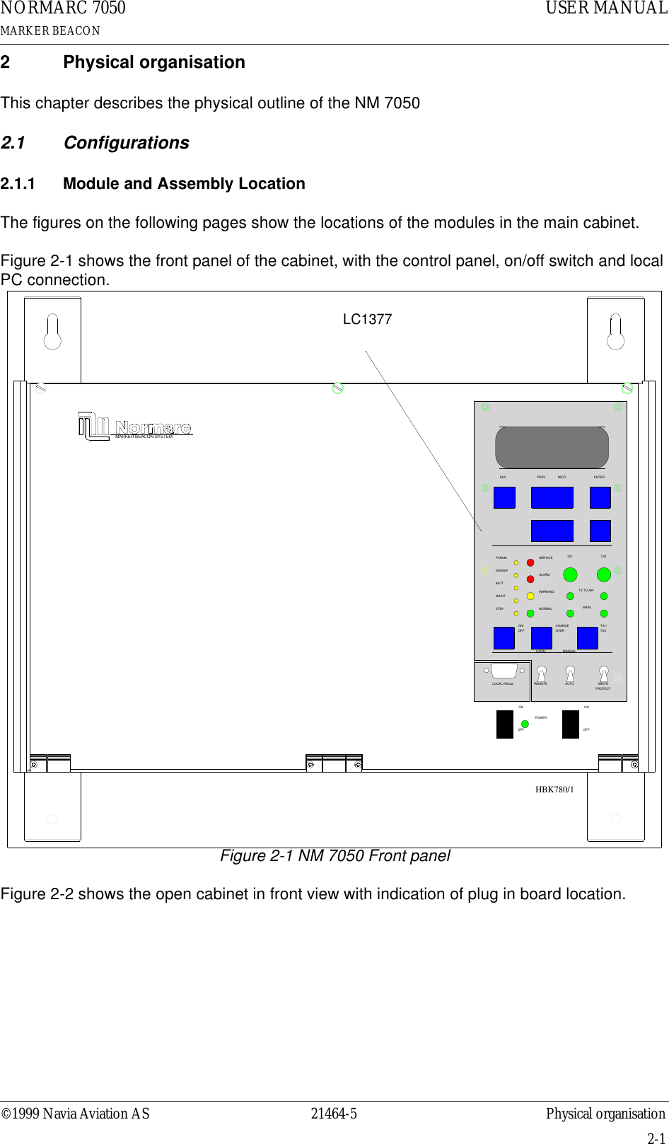
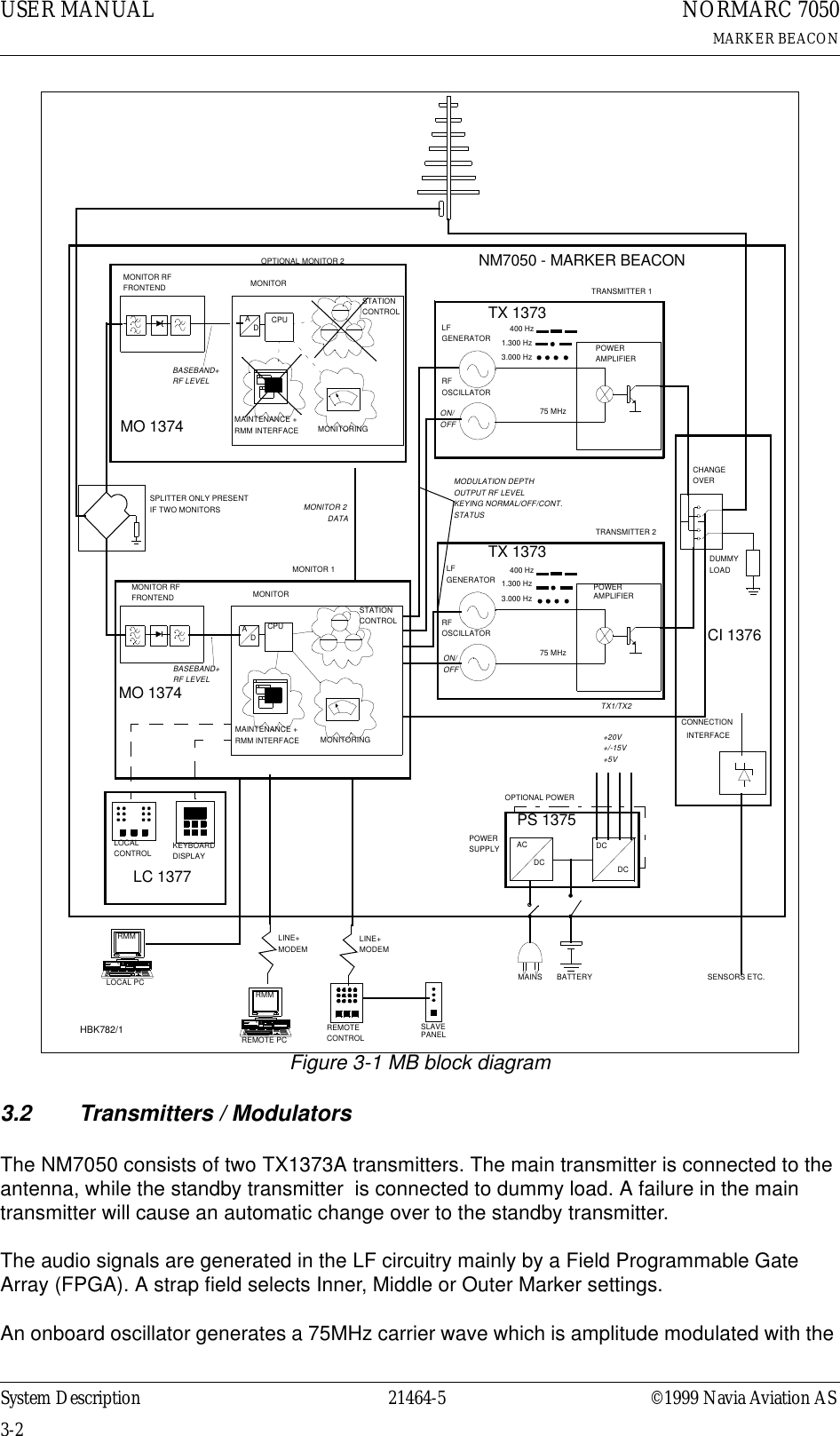
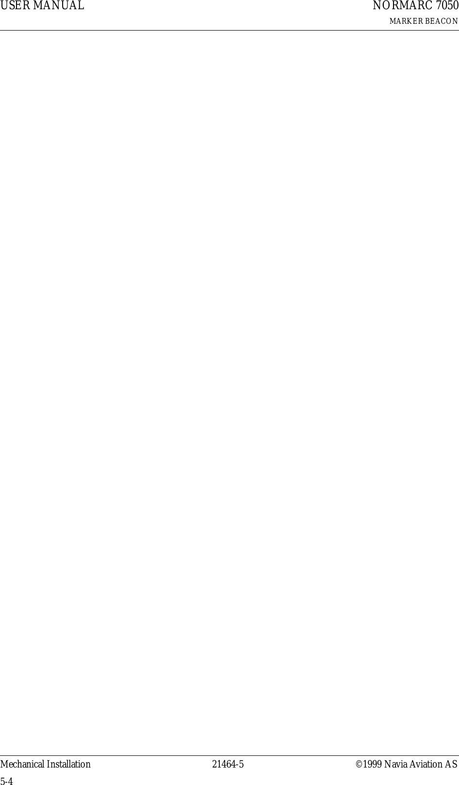
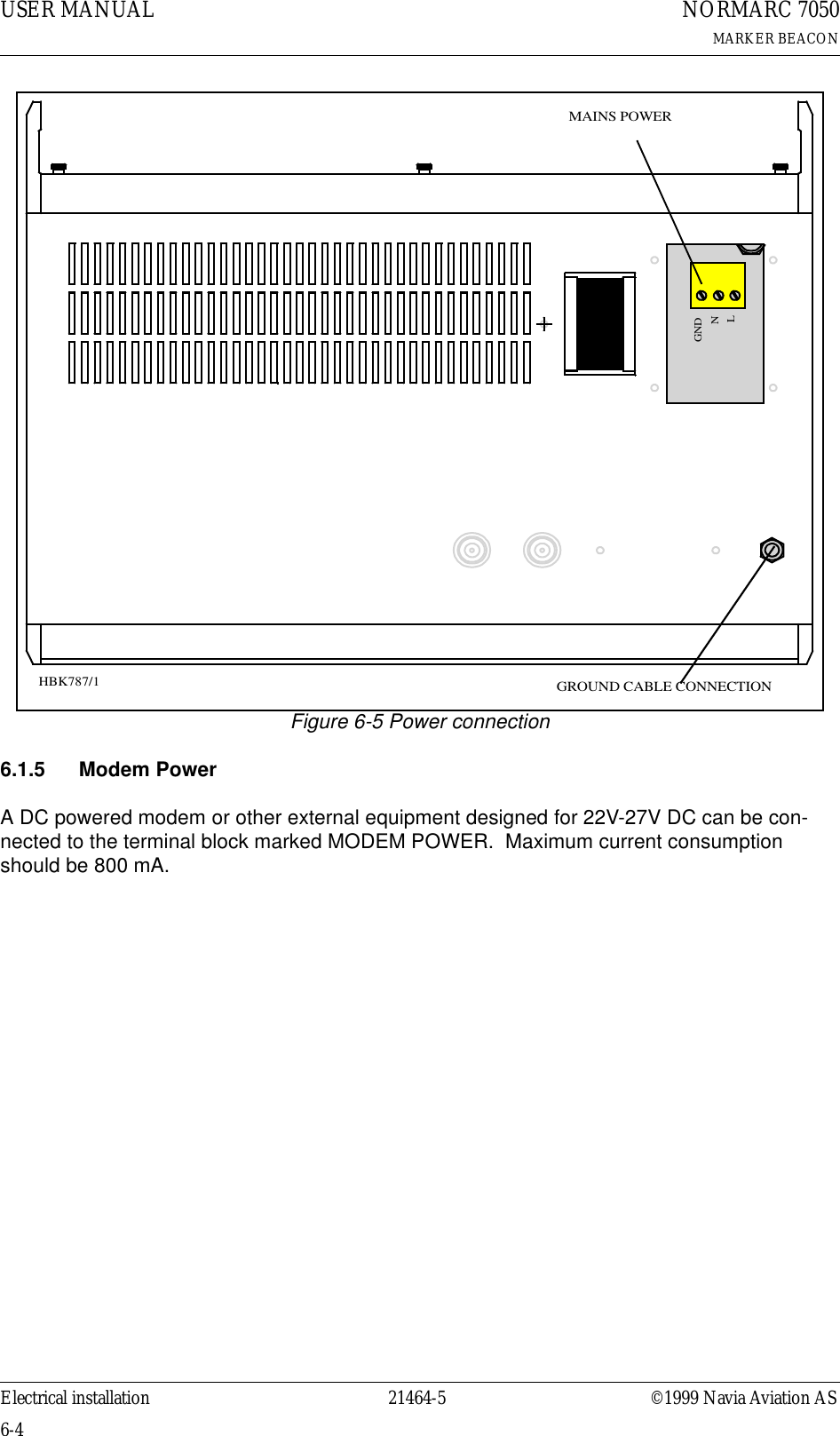
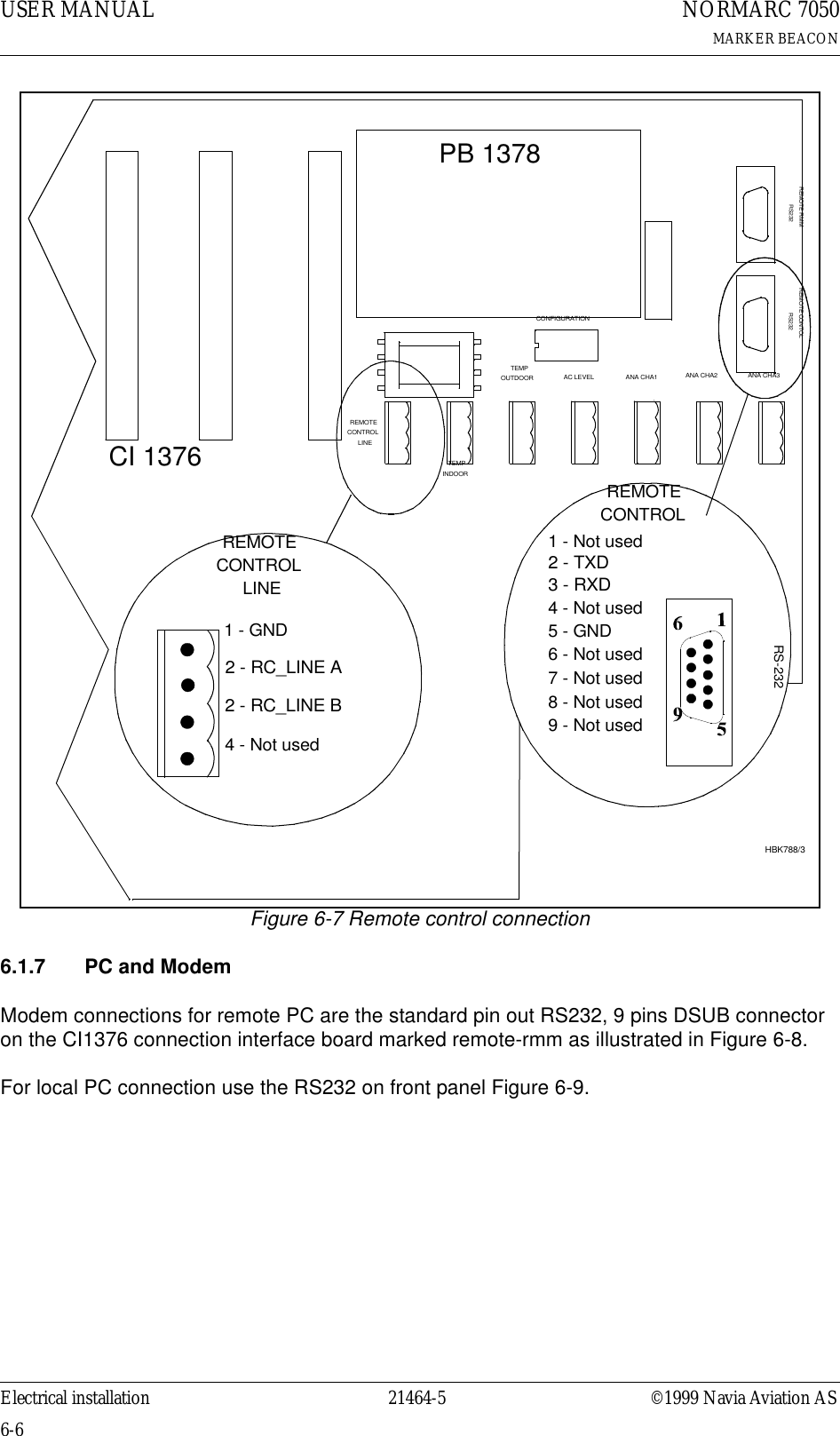
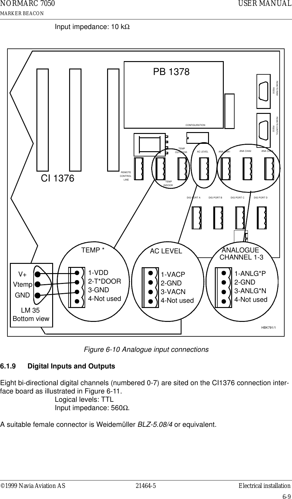
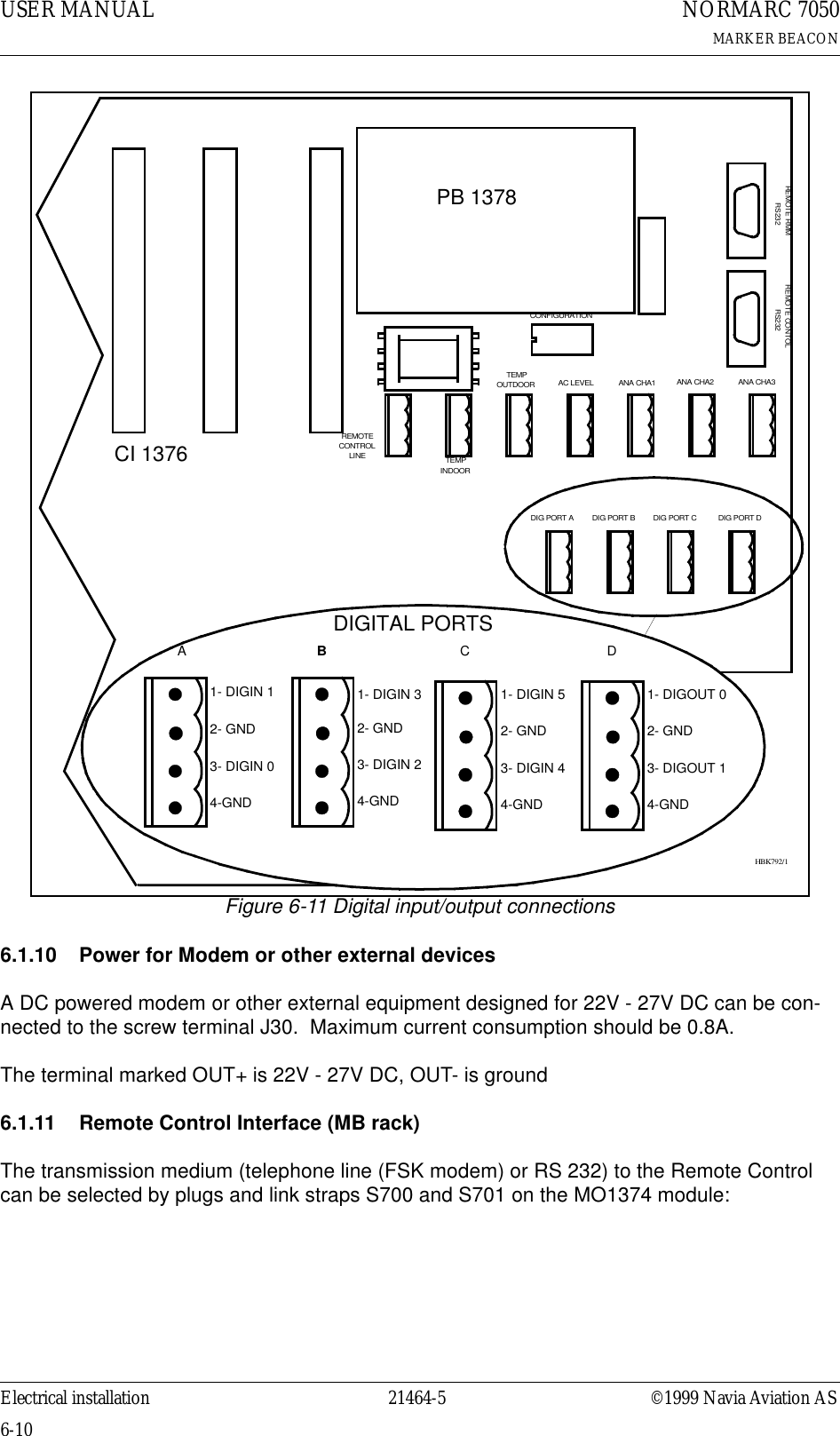
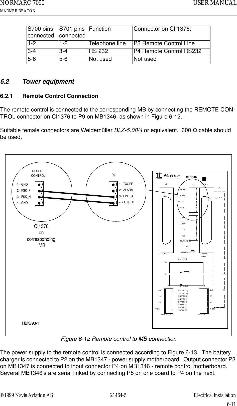
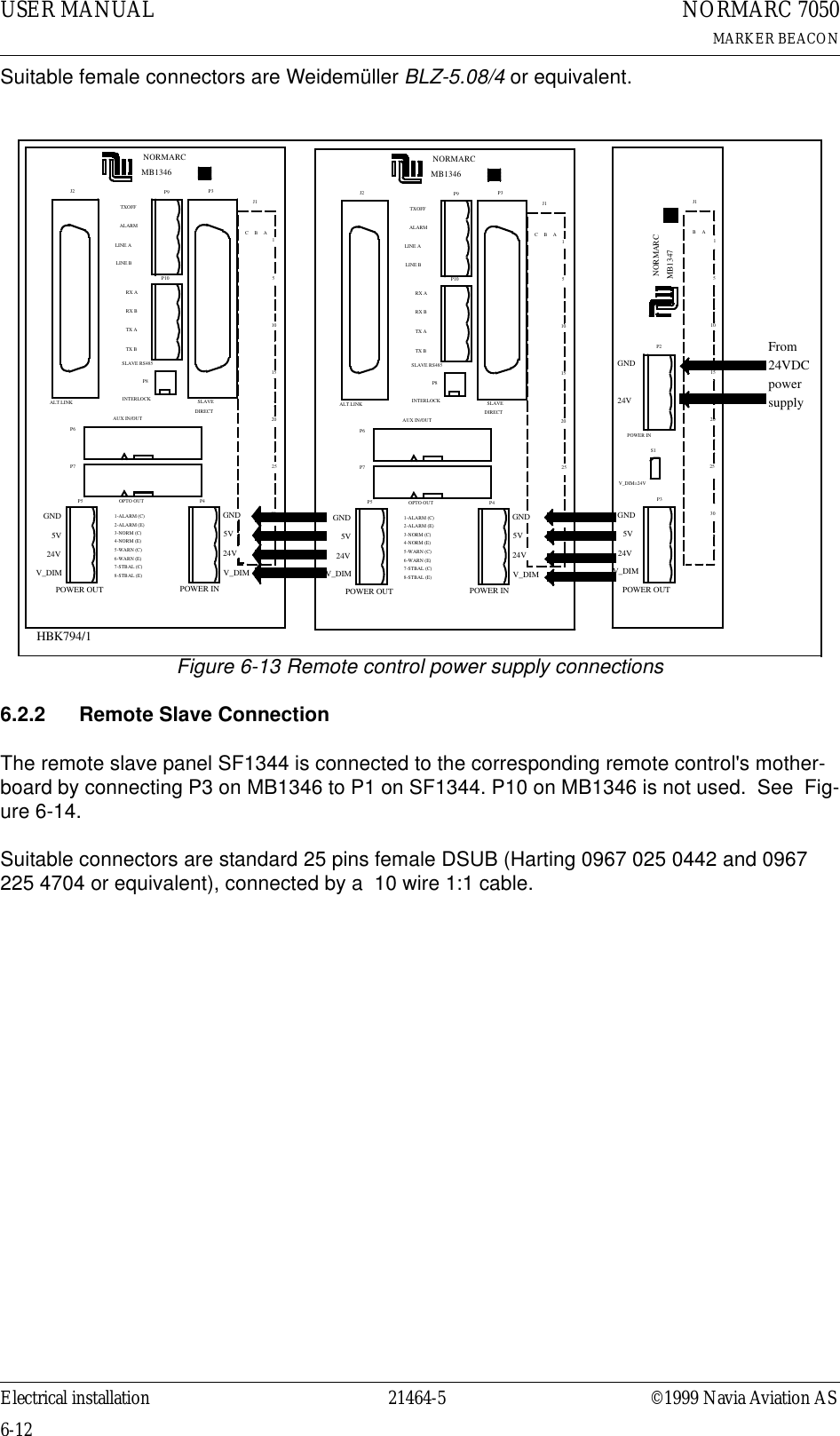
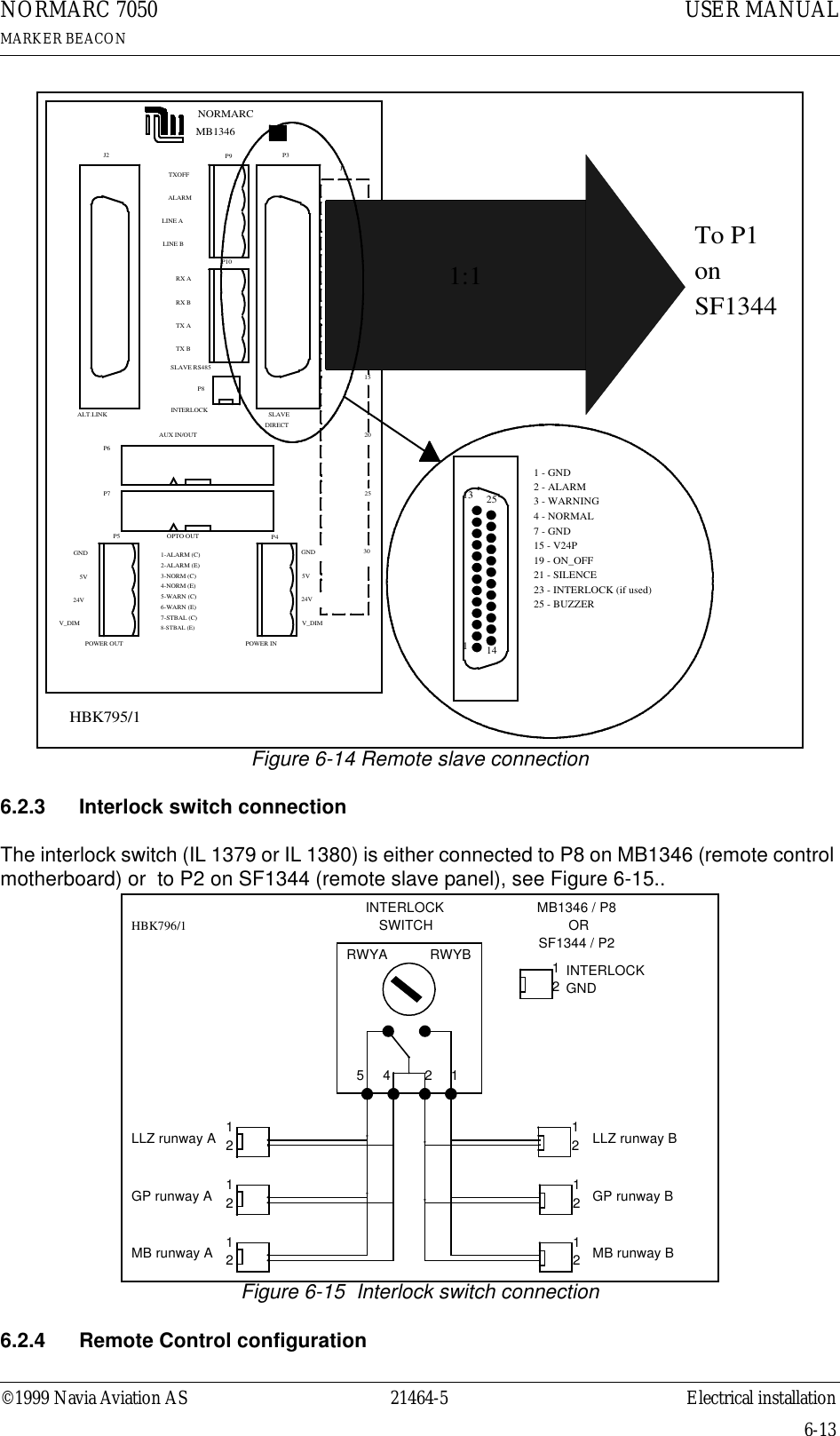
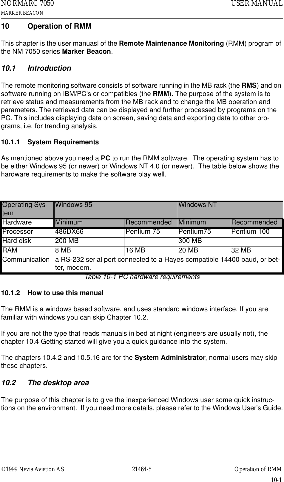
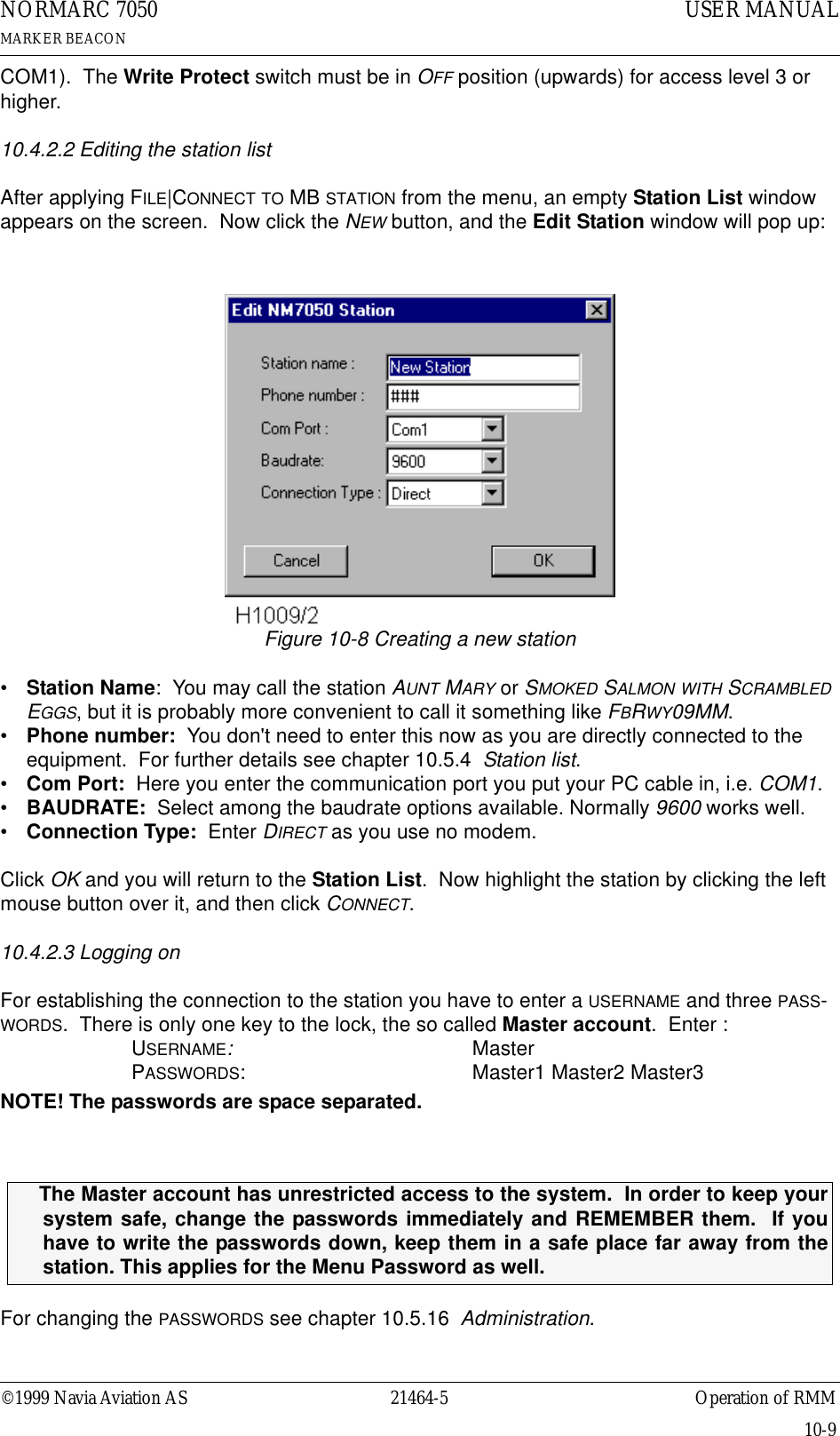
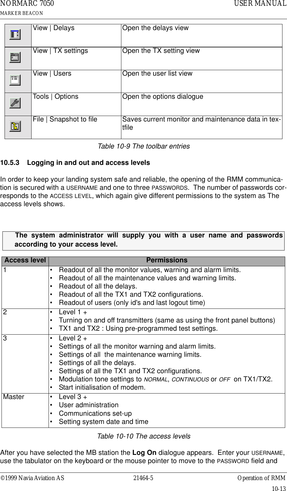
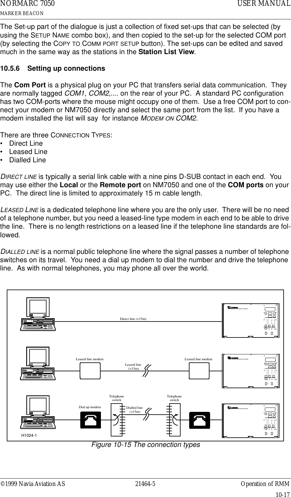
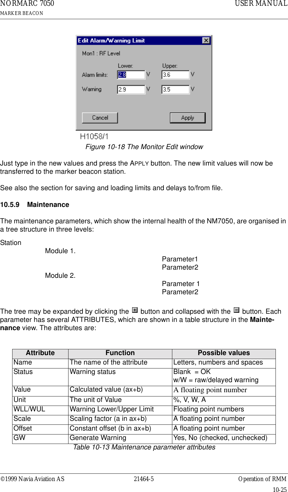
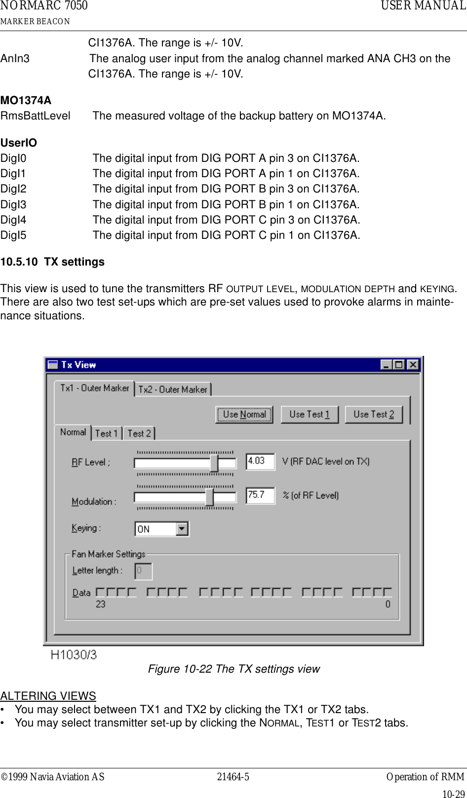
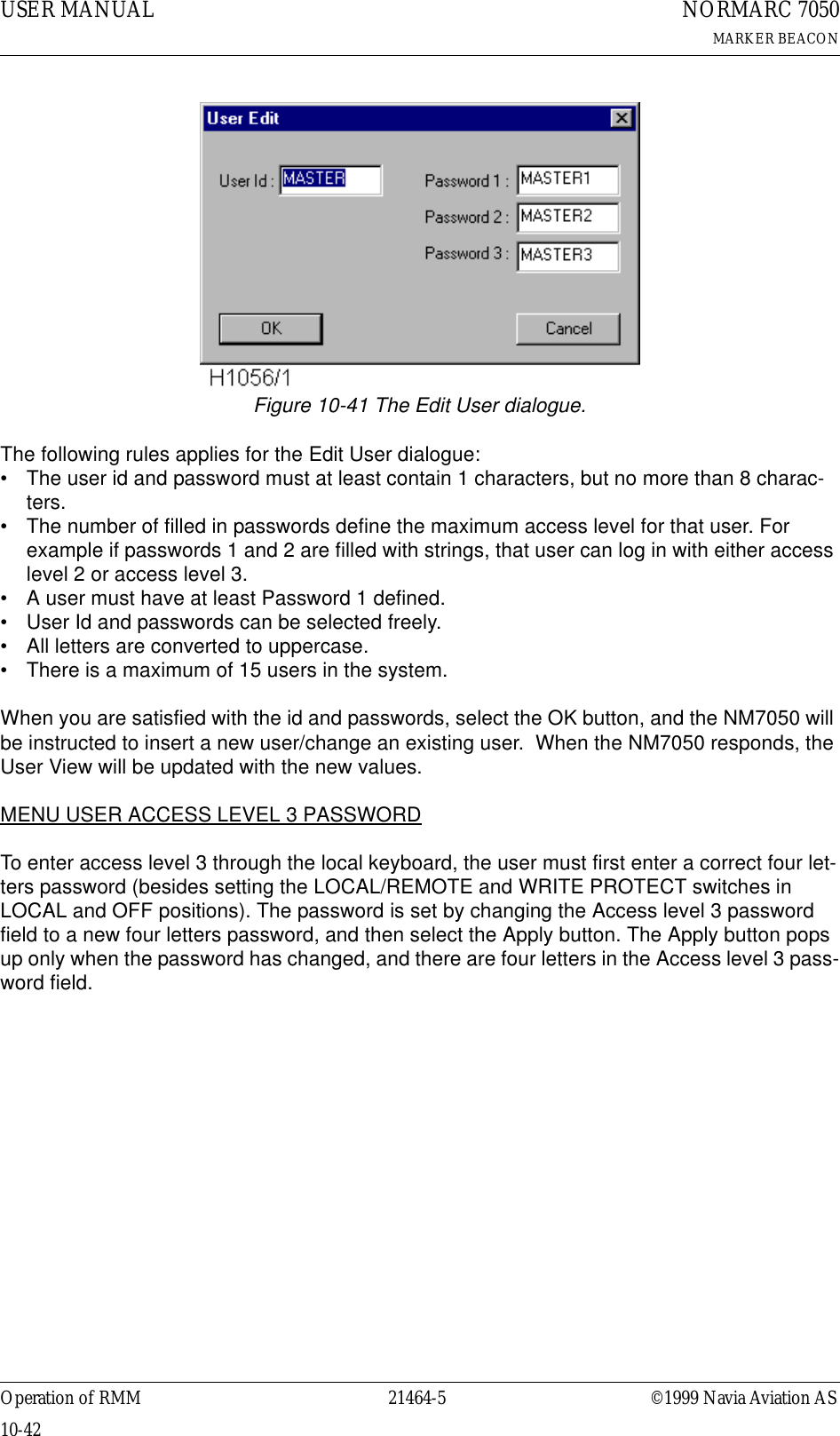
![©1999 Navia Aviation AS 21464-5 Electrical installationUSER MANUALNORMARC 7050MARKER BEACON6-5Figure 6-6 Modem Power6.1.6 Remote ControlThe remote line and remote control is connected to the CI 1376 connection interface board as illustrated in Figure 6-7. • FSK_[A,B] is the modem line pair.• GND is main cabinet groundA suitable female connector for the remote line is Weidemüller BLZ-5.08/4 or equivalent.Alternatively the remote control connection is done with a RS 232 interface. The mode is con-figured on MO 1374, refer to 7.2.3.Note: The position of RXD and TXD is interchanged from the normal RS-232 layout in the Remote Control connector. Therefore a special cable must be used for connection to external equipment.CI 1376REMOTECONTROLLINETEMPOUTDOORTEMPINDOORAC LEVEL ANA CHA1 ANA CHA2 ANA CHA3DIG PORT A DIG PORT B DIG PORT C DIG PORT D-(GND)123BATT GNDEXT CHARGEBATT +24VBATTERY- ++ (+24V DC)MODEM POWERMODEM POWERH1116/1](https://usermanual.wiki/Leidos/NORMARC7031.7031-User-Manual/User-Guide-103315-Page-39.png)
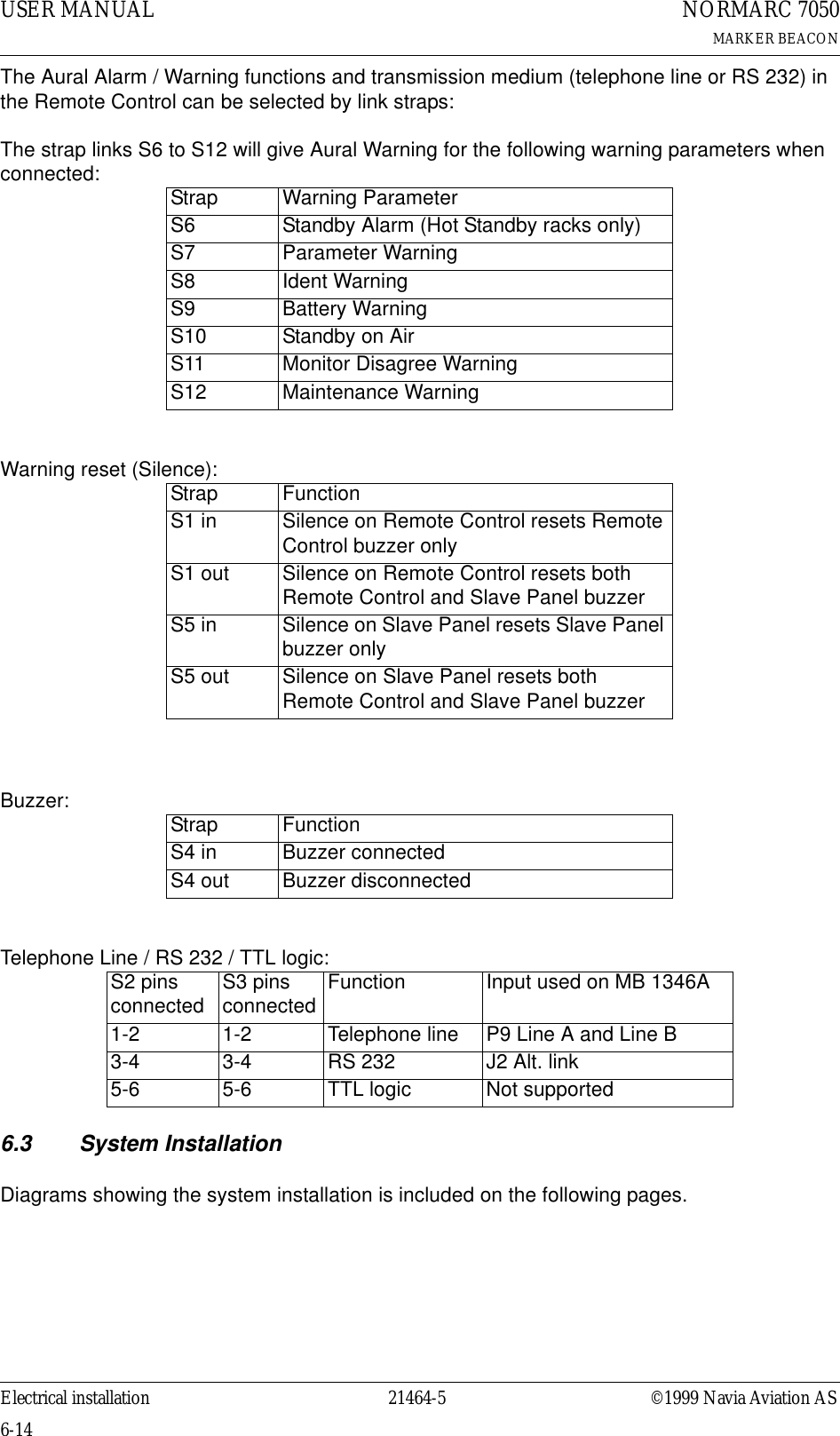
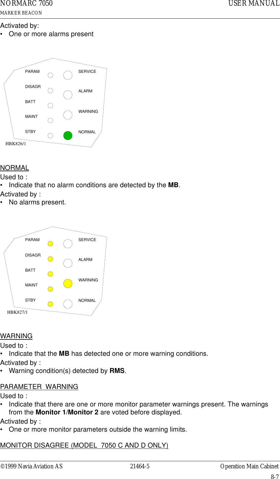
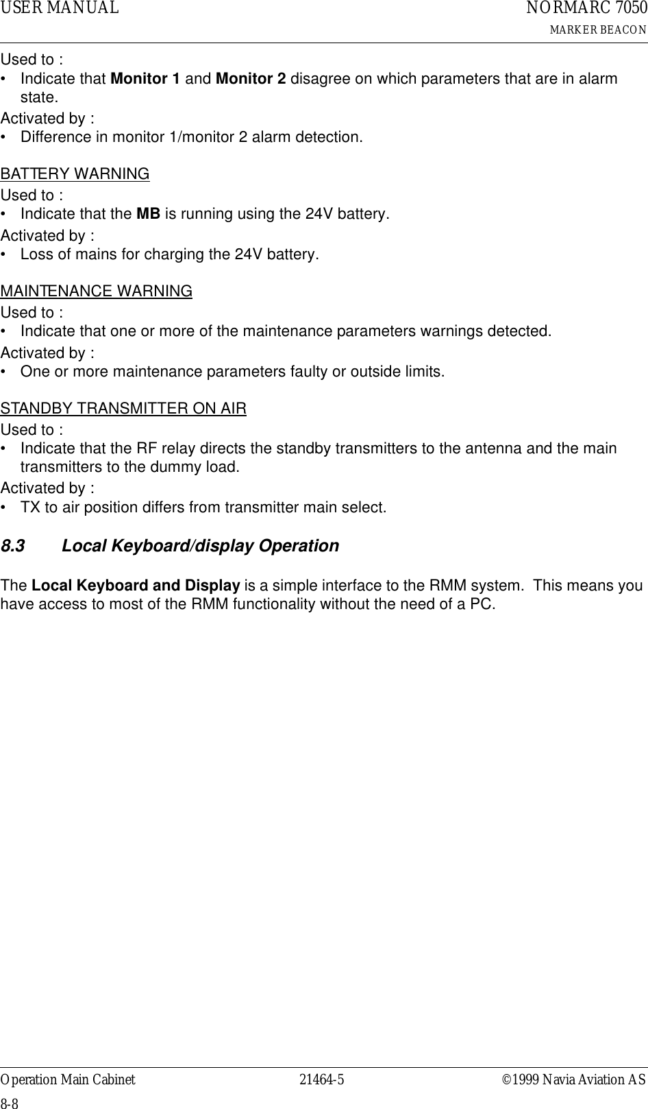
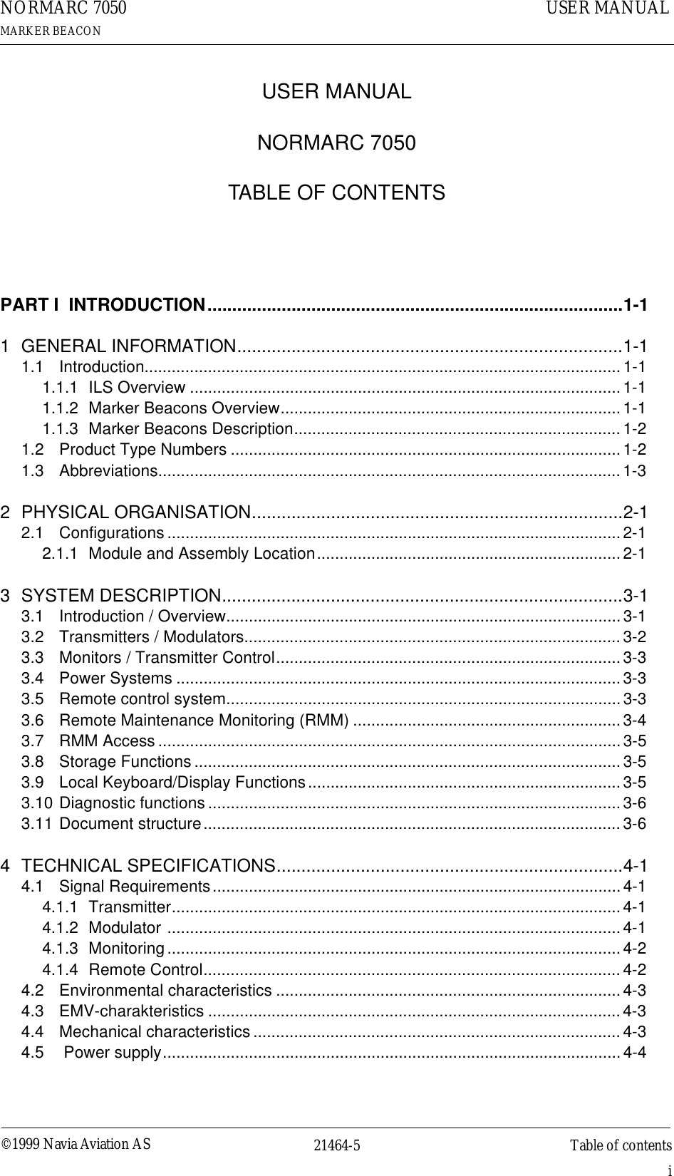
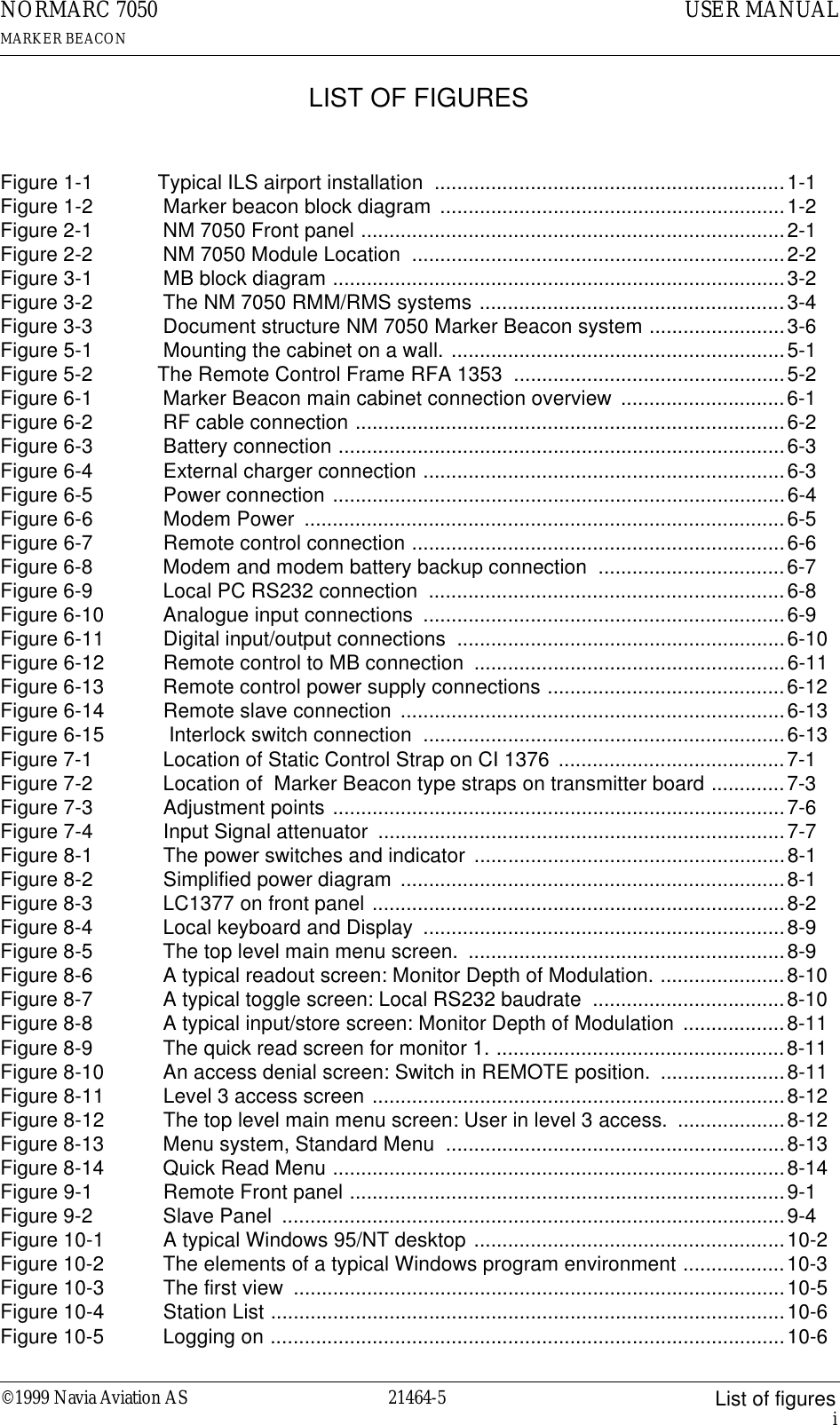
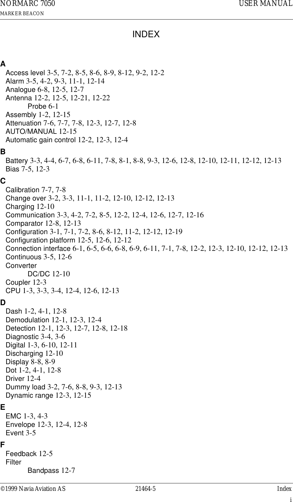
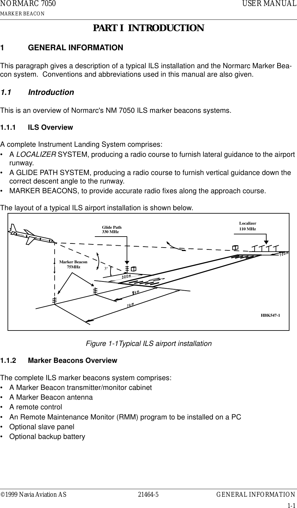
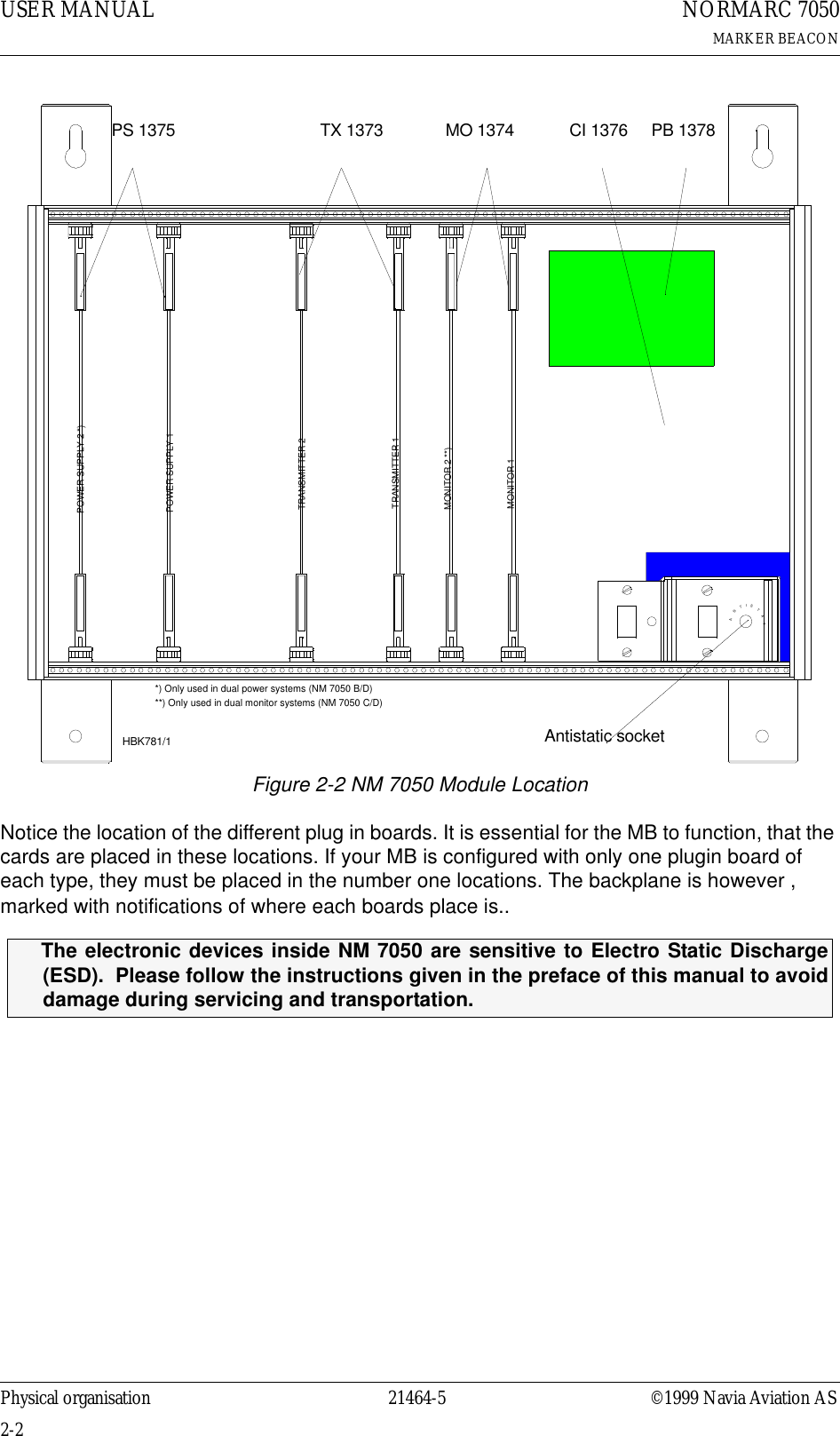
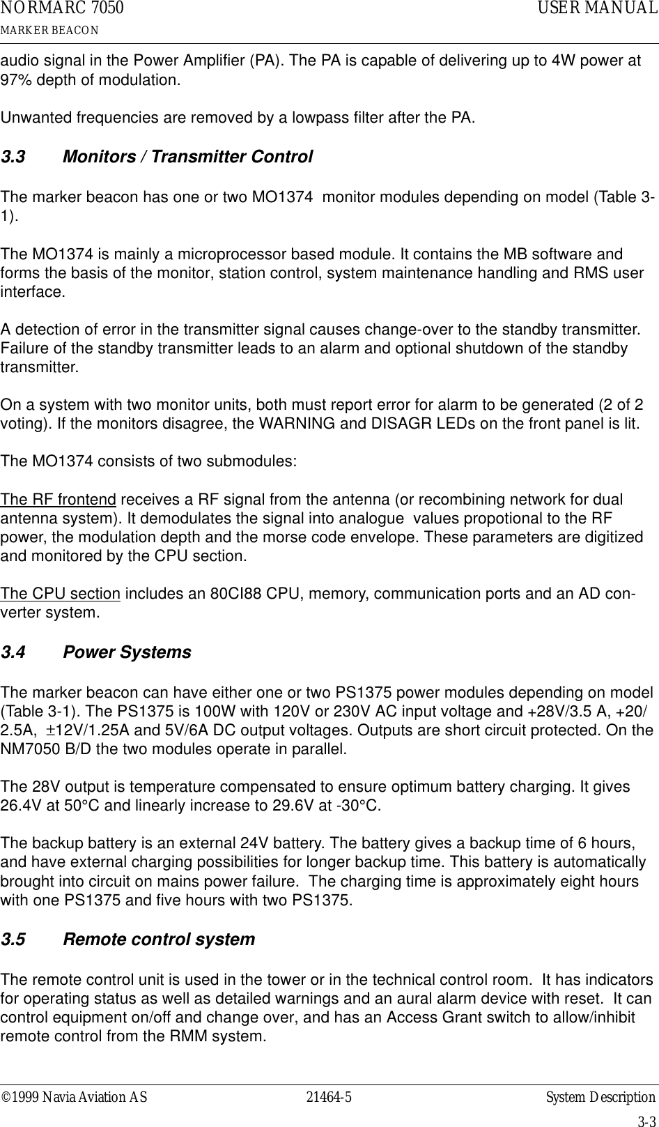
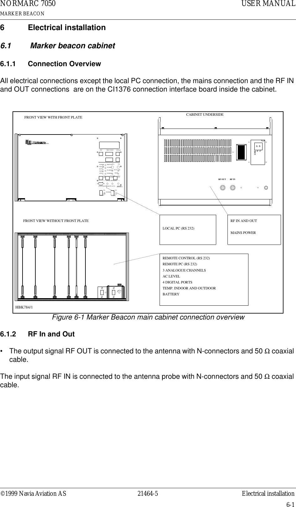
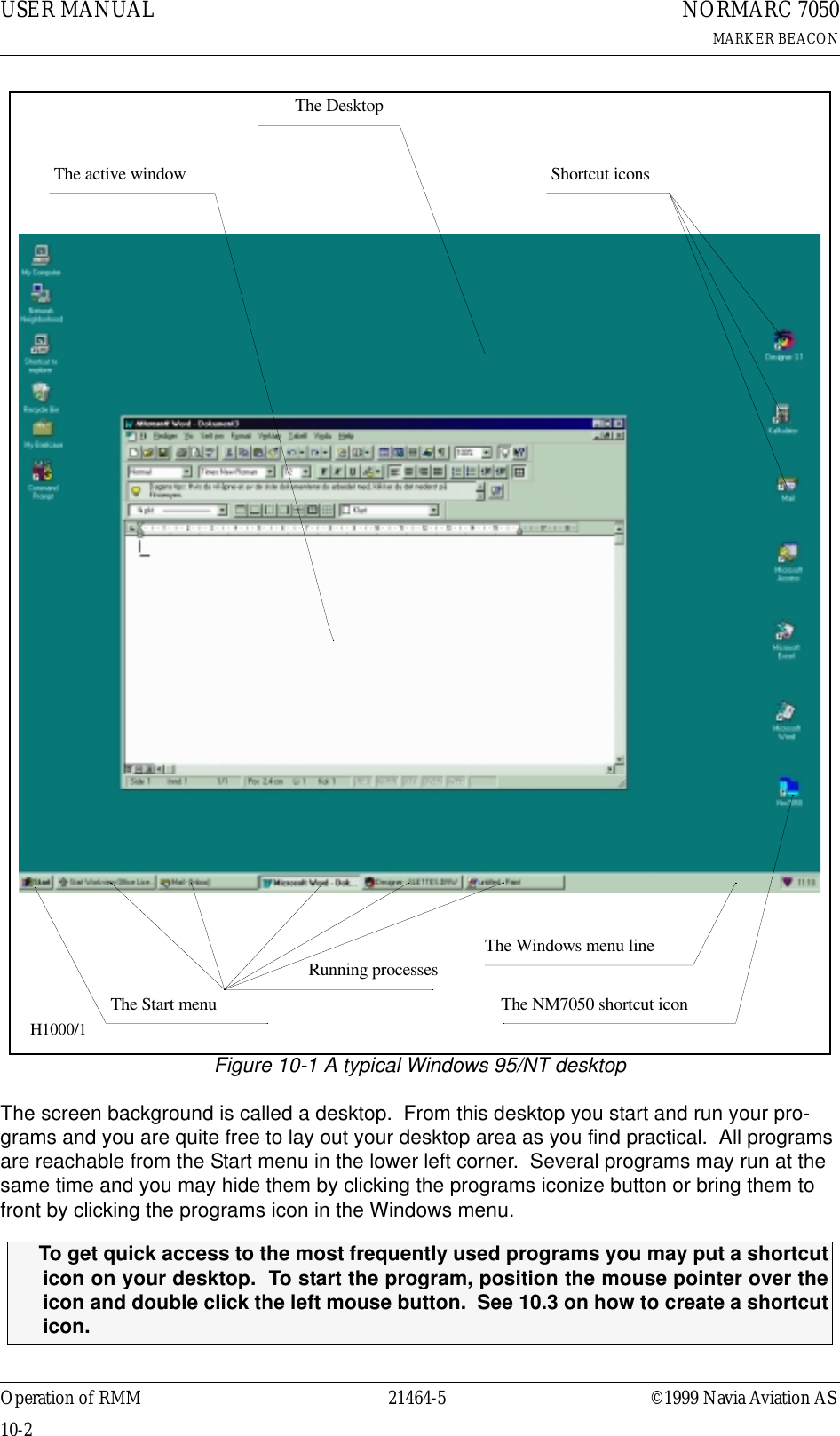
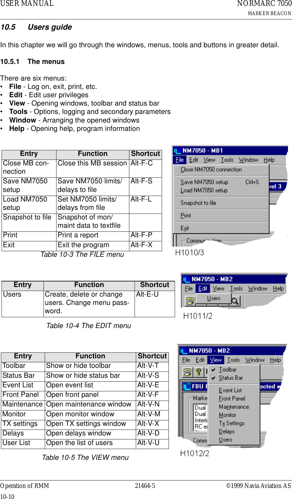
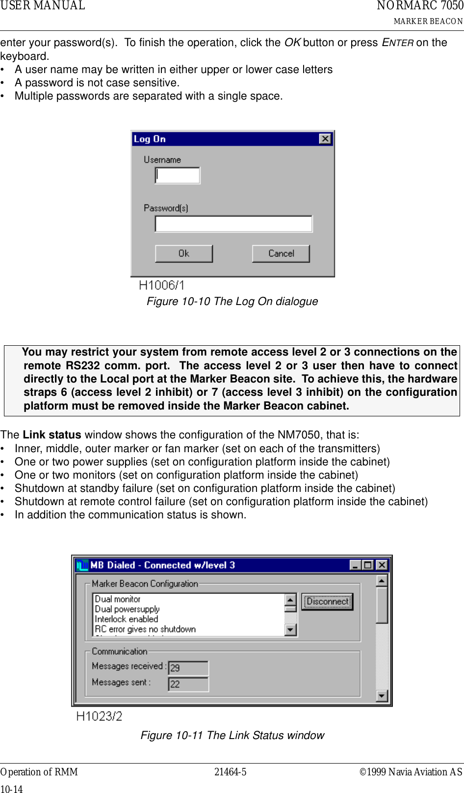
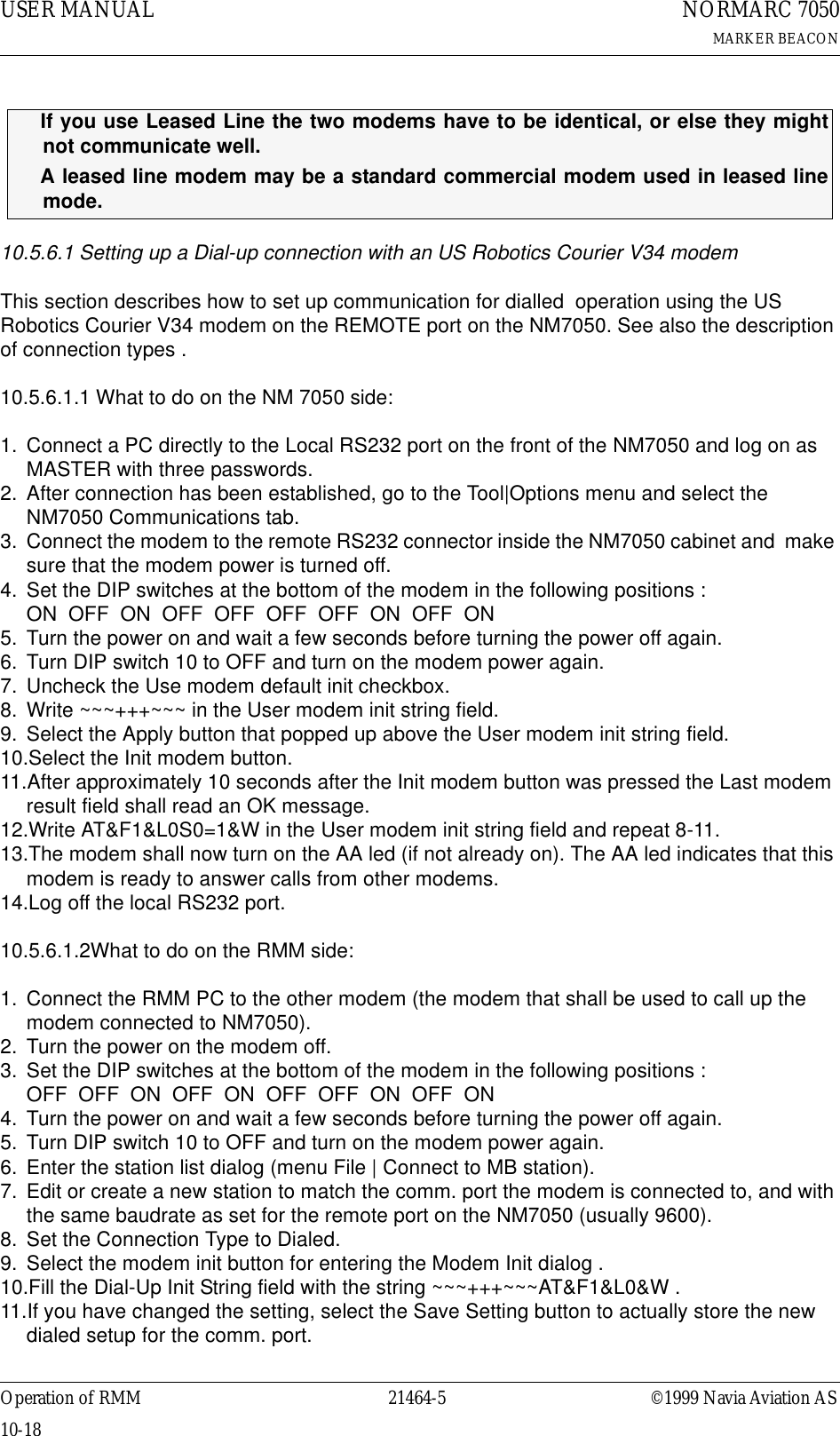
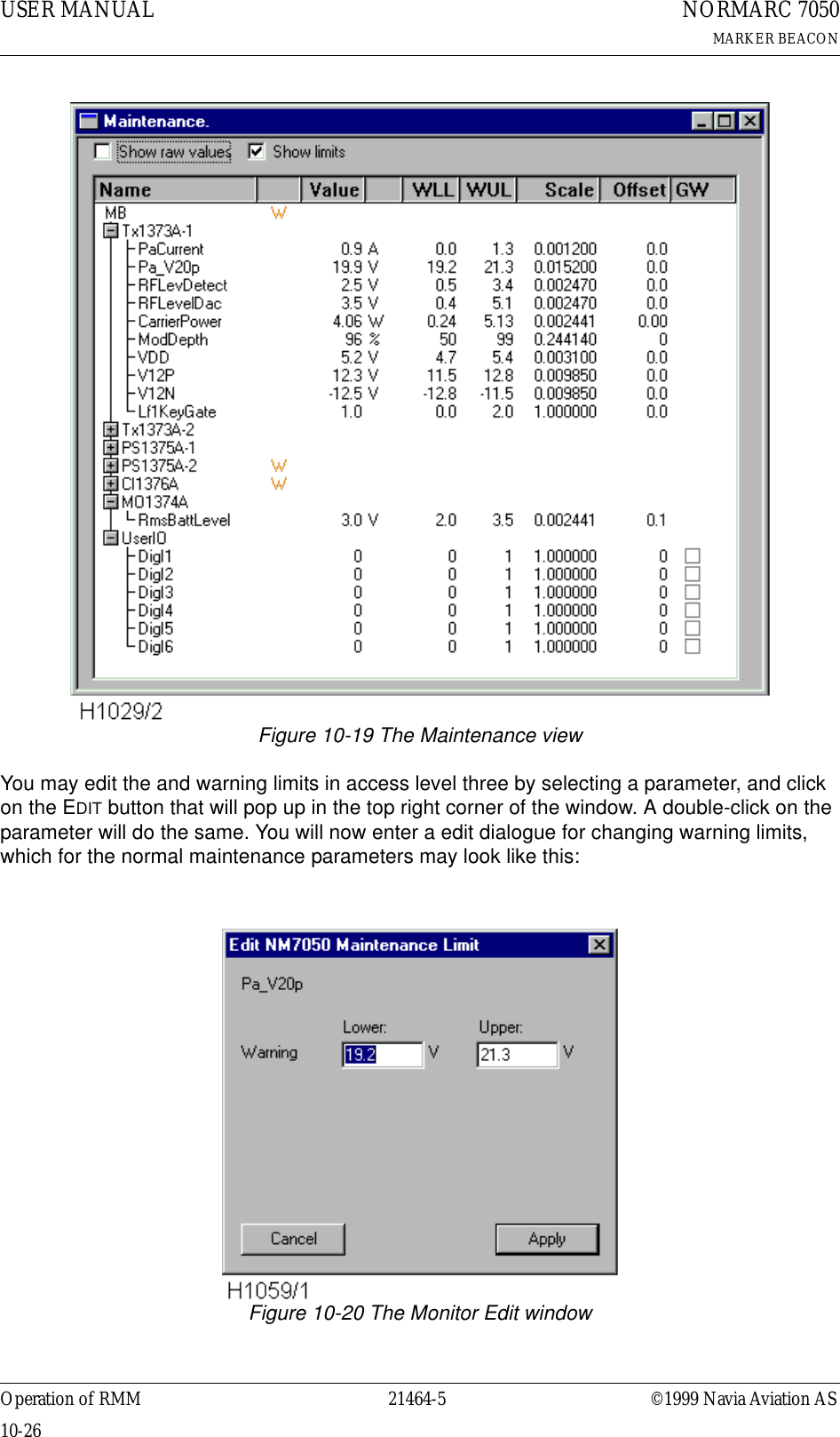
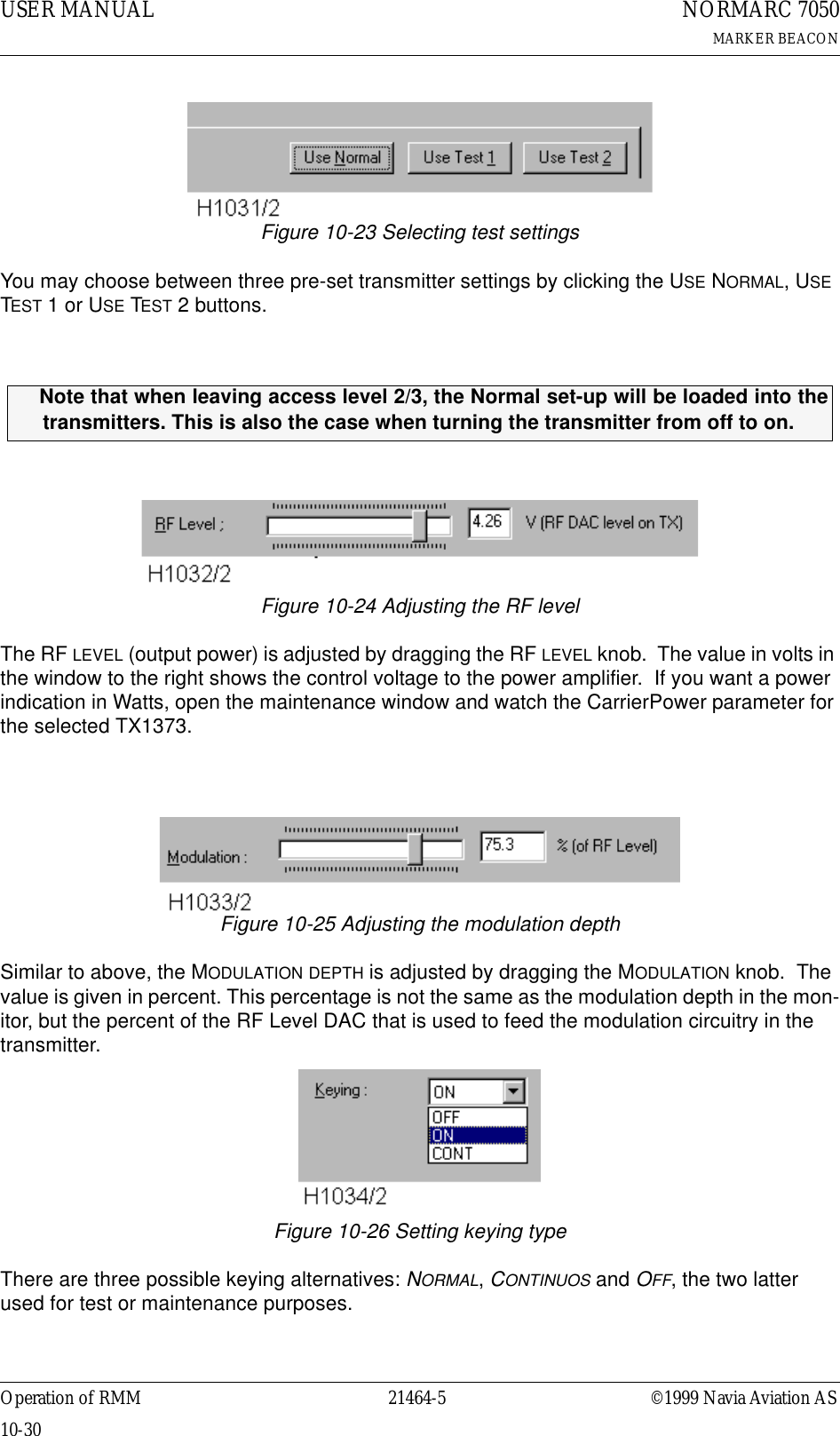
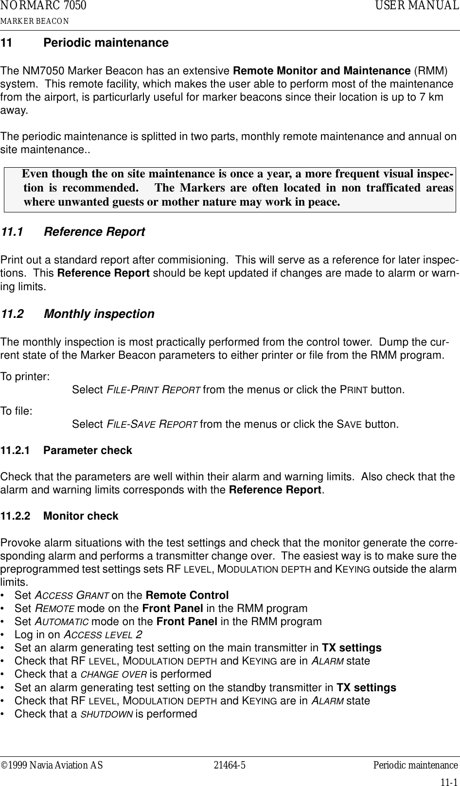
![USER MANUAL8-1021464-5NORMARC 7050MARKER BEACONOperation Main Cabinet ©1999 Navia Aviation ASscreens, input/storing screens, and the quick read screens.8.3.2.1 The menu screenThe menu screen is controlled by the key-buttons : PREV , NEXT , ENTER and ESC.The menu options are formatted as a long list where each option holds one character line. If a menu screen includes more than four options, a small arrow-indicator will be displayed in the lower right corner. This informs the user that more than four menu options are available. The blinking arrow cursor left to the menu text is controlled by the NEXT and PREV keys. The ENTER key activates the menu options left to the arrow-cursor.The ESC key brings the user one menu-level upwards or back in the menu-tree-structure.The menu scrolls down if the user pushes the NEXT key when the arrow-cursor is at the lower line and the arrow indicator is displayed in the lower right corner. The menu will in the same way scroll upwards by pushing the PREV-key in a corresponding situation.8.3.2.2 The readout screenThe readout screens display the various monitor and maintenance parameter readings. The screens are entered by stepping through the menu options. The ESC key brings the user back to the previous menu screen again. The parameter readings are continuously updated..Figure 8-6 A typical readout screen: Monitor Depth of Modulation.8.3.2.3 The toggle screensThe toggle screens offer the user to choose between two or more options. The options text is enclosed by two blinking square-brackets. The plus «+» and minus «-» keys step through the various options. The ENTER key activates the chosen toggle option. The ESC keys leaves the screen without activating any of the options.Figure 8-7 A typical toggle screen: Local RS232 baudrate8.3.2.4 Input/Store screenThe user can change the various parameter alarm and warning settings in the input/storing-screens. A virtual cursor is controlled by the PREV and NEXT keys. An input field number will blink if the cursor is moved to the correct position. The blinking limit values can now be changed by pushing the plus «+» and minus «-» keys. If the input field is digital, the valid options will be FALSE and TRUE when the plus «+» and minus «-» keys are pushed.When all the input numbers in the screen are changed to the preferred new values, the cursor must be moved to the STORE-field in the upper left corner. When the cursor is placed at this readout M1 Rf Mod. Mod. : 95.2%Al U 99.0% L 91.0% Wa U 98.0% L 93.0% Set bitrate Local [ 9600 ]](https://usermanual.wiki/Leidos/NORMARC7031.7031-User-Manual/User-Guide-103315-Page-66.png)
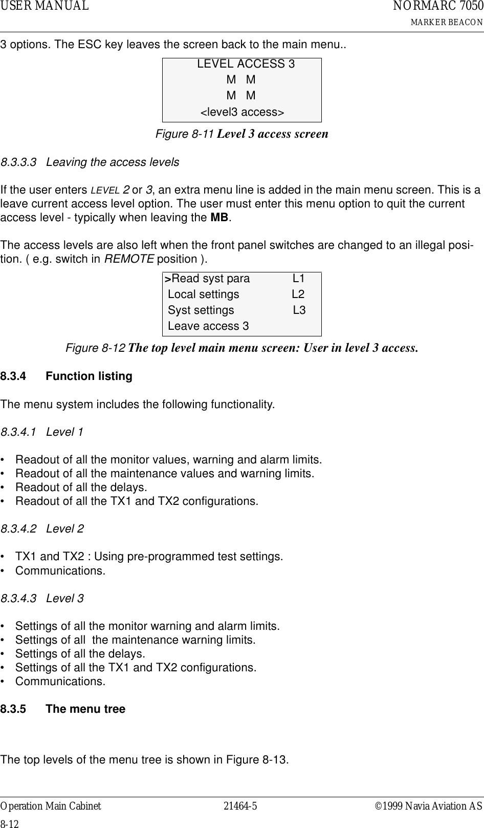
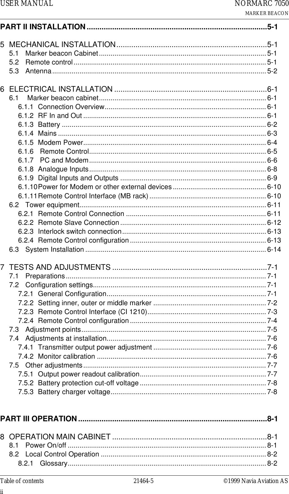
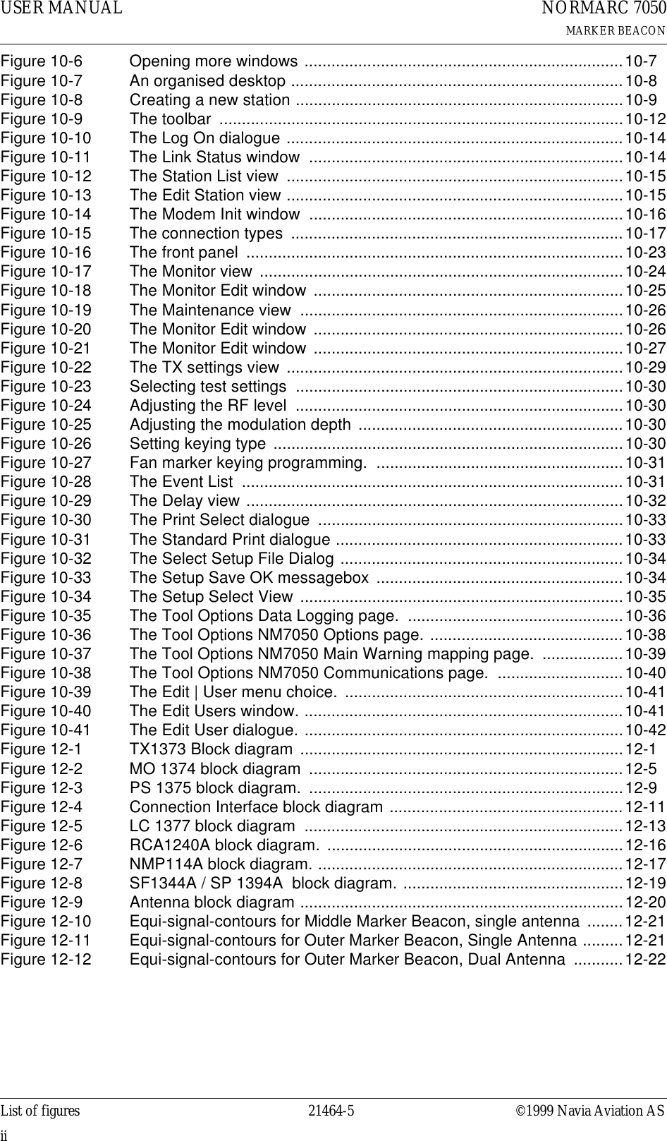
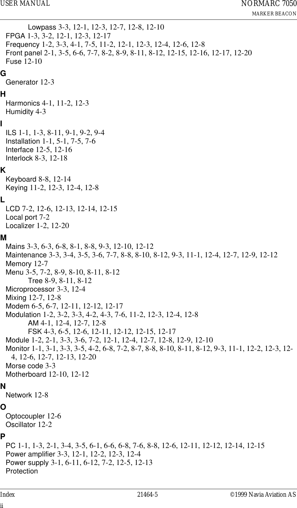
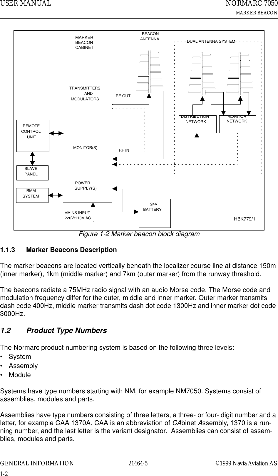
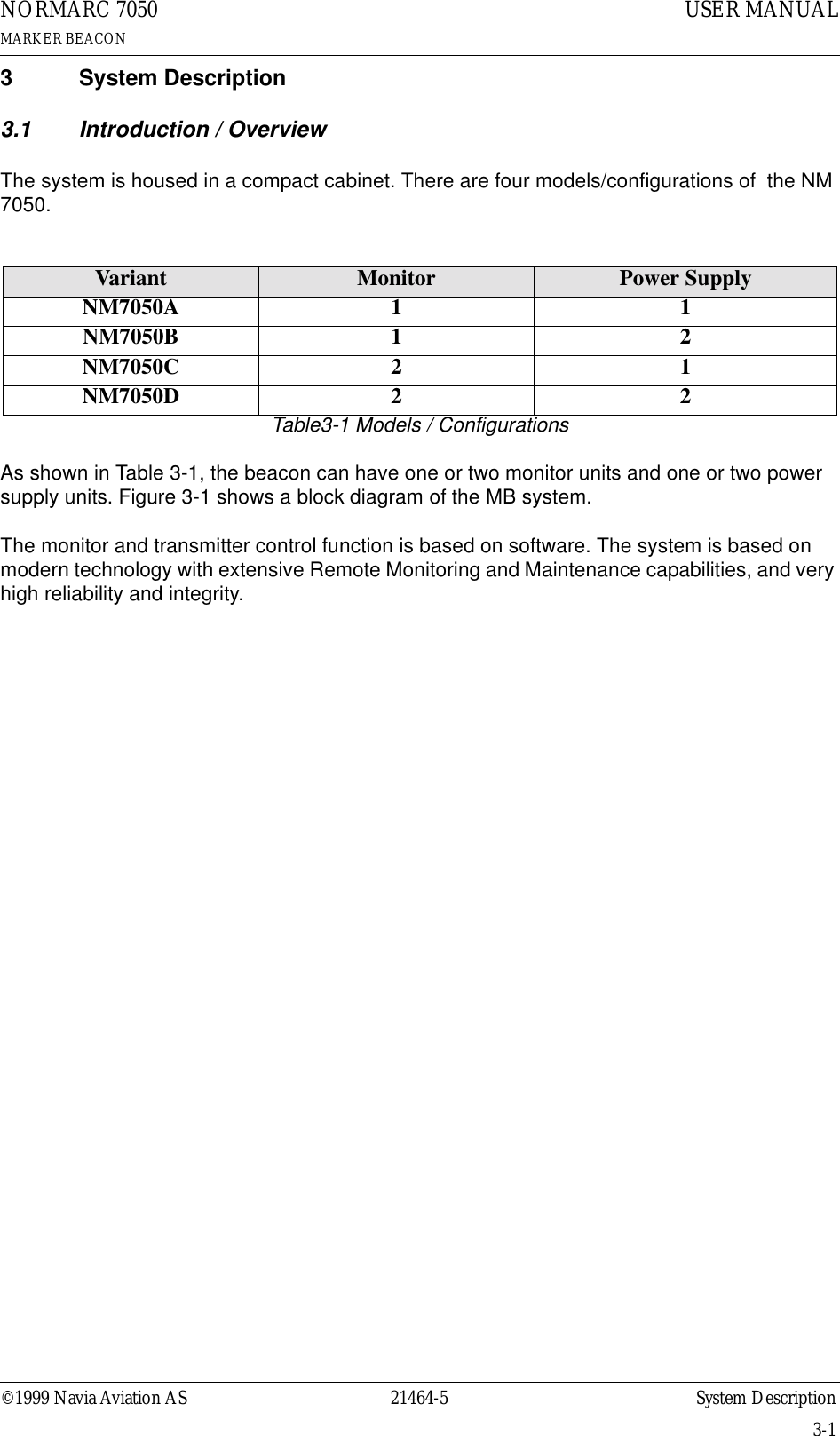
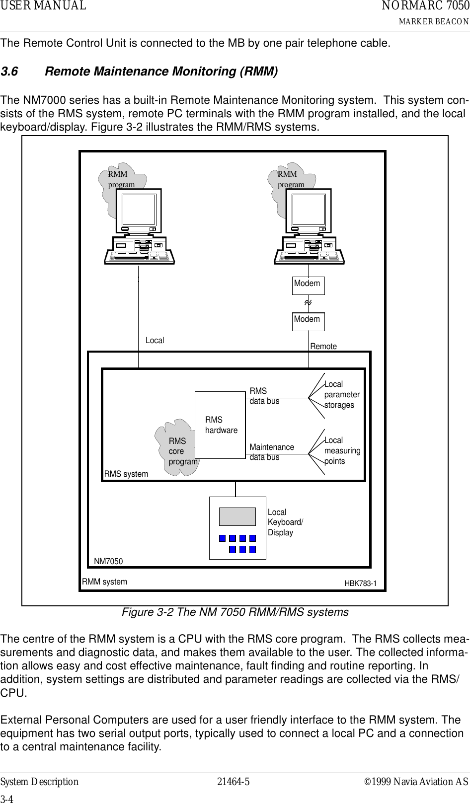
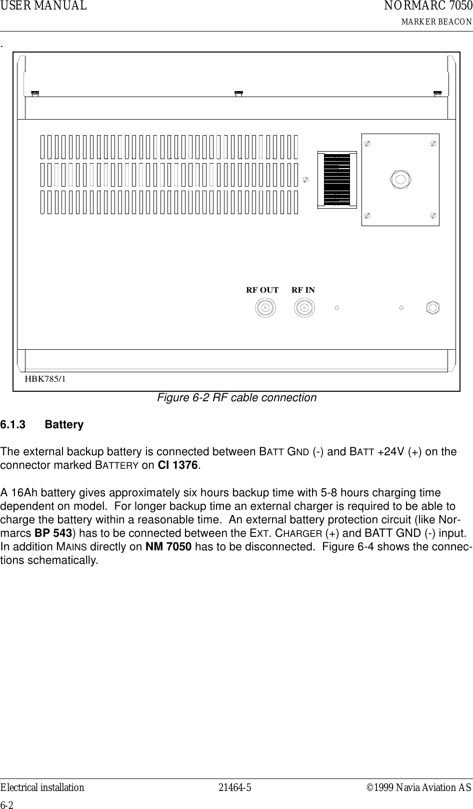
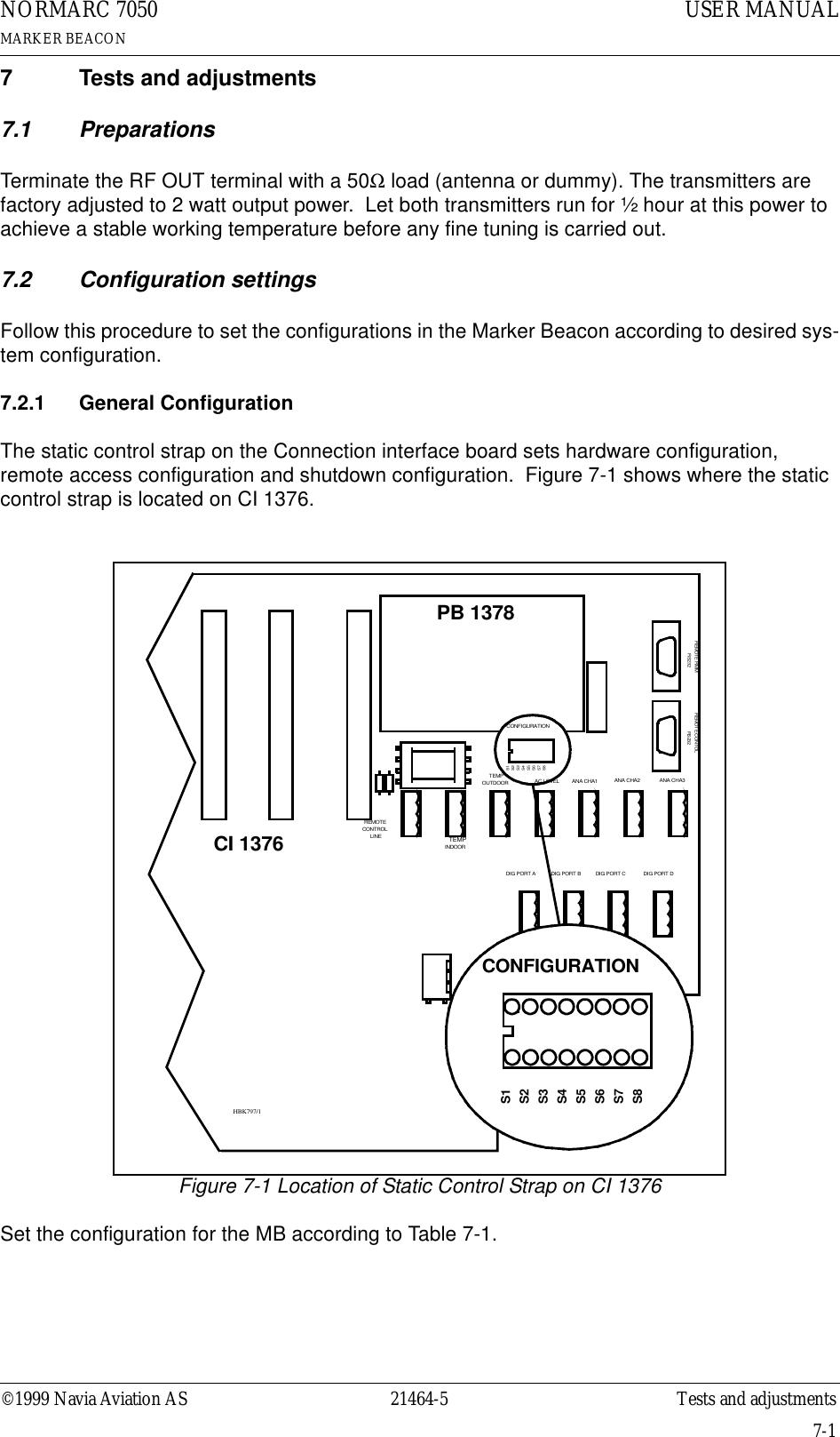
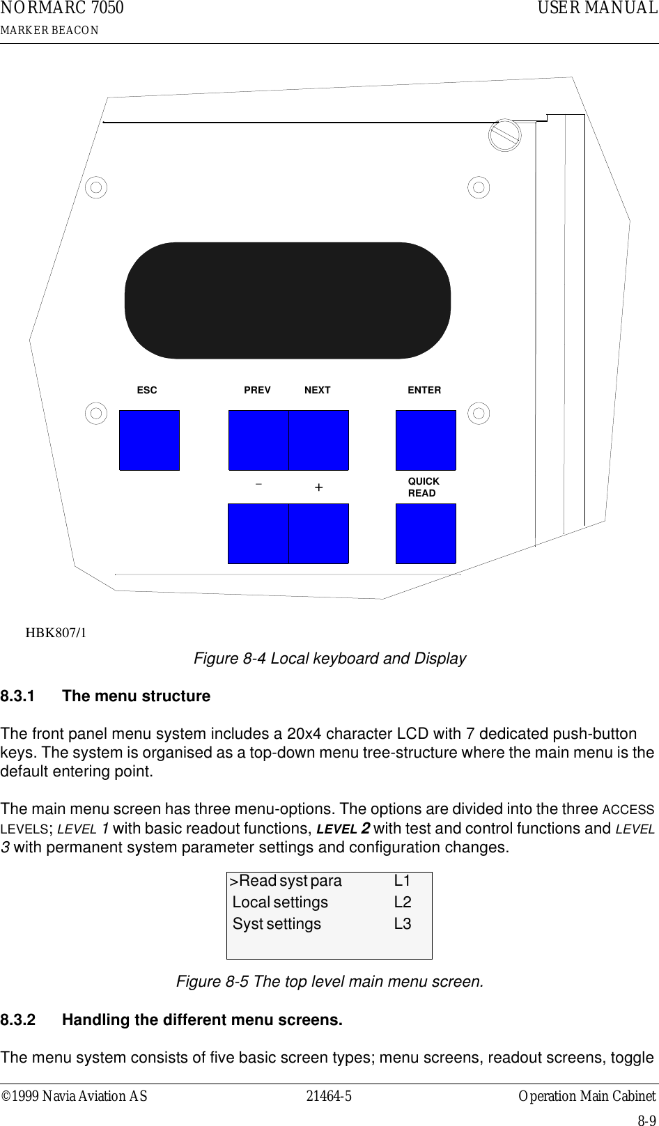
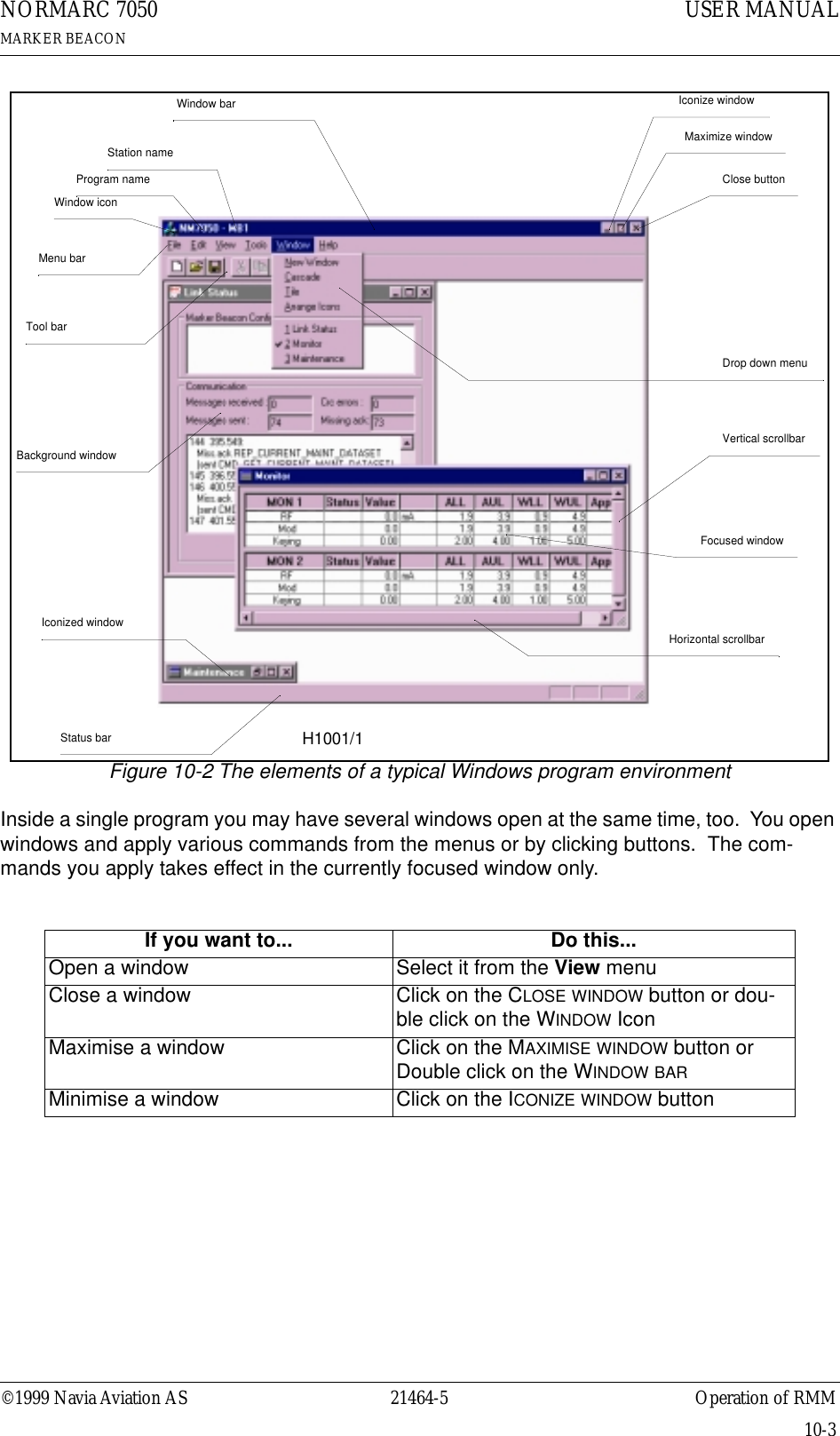
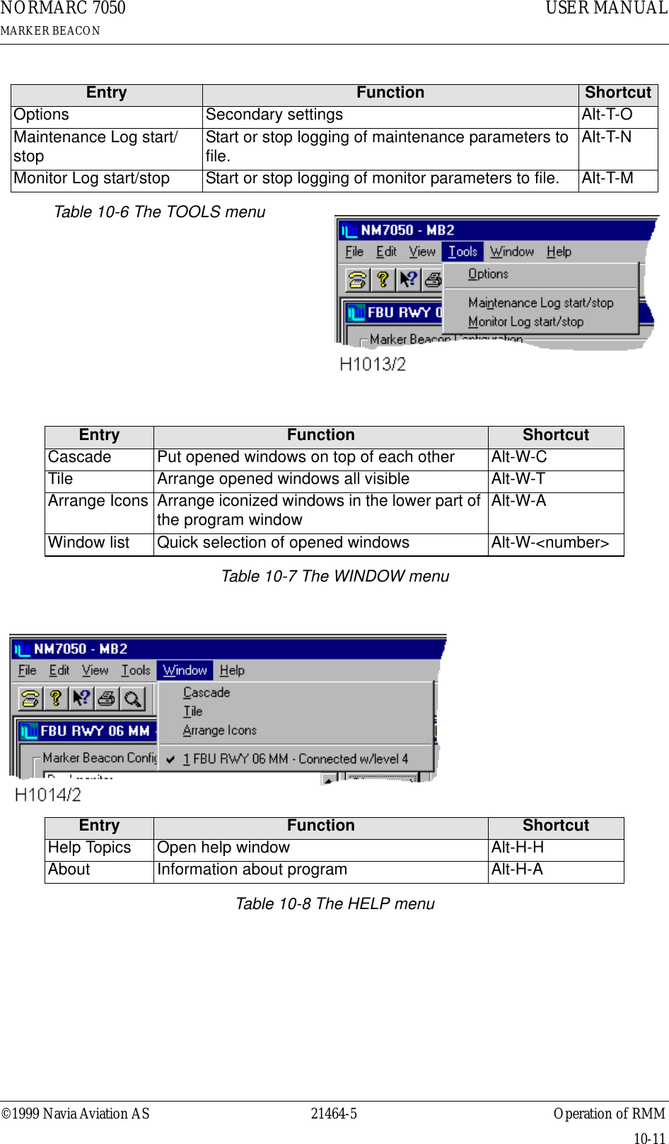
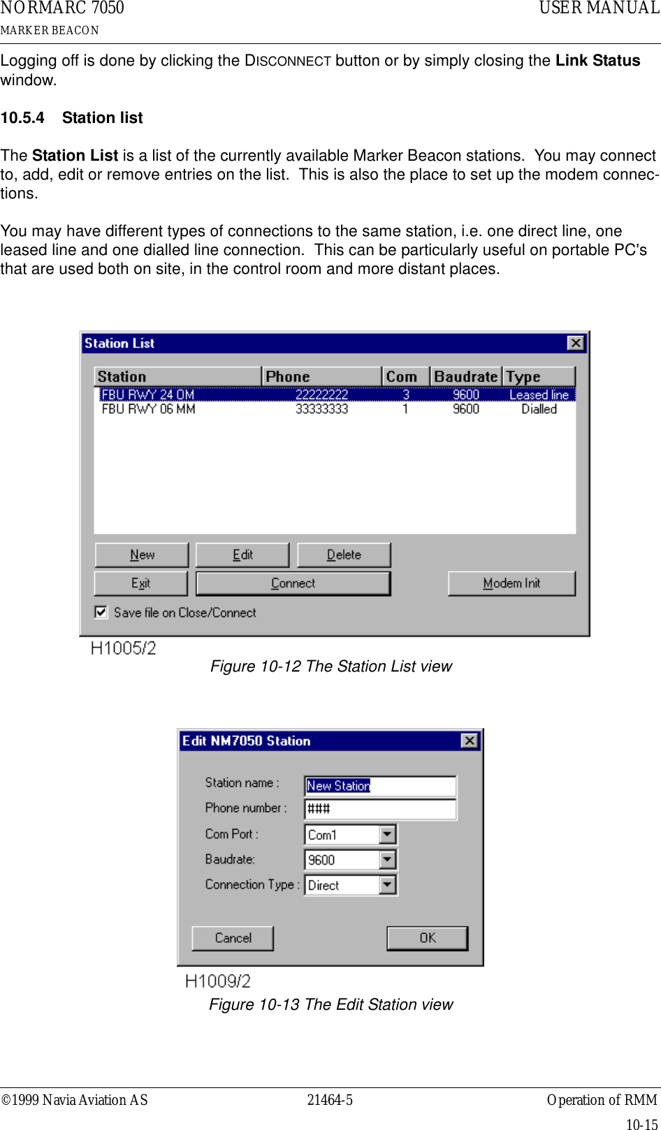
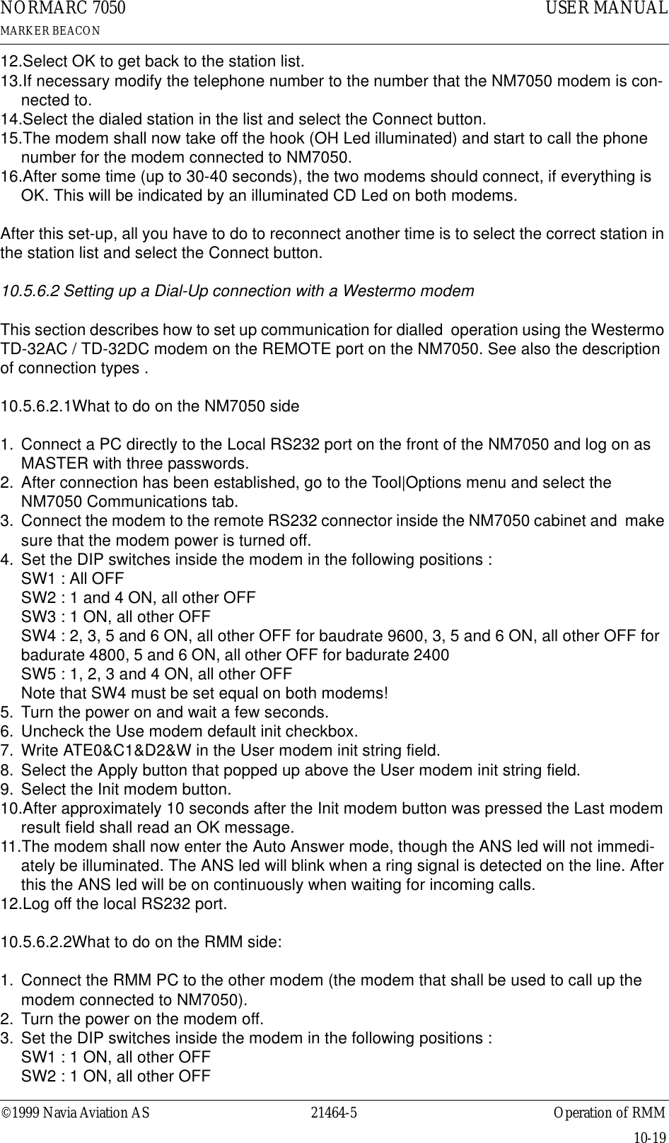
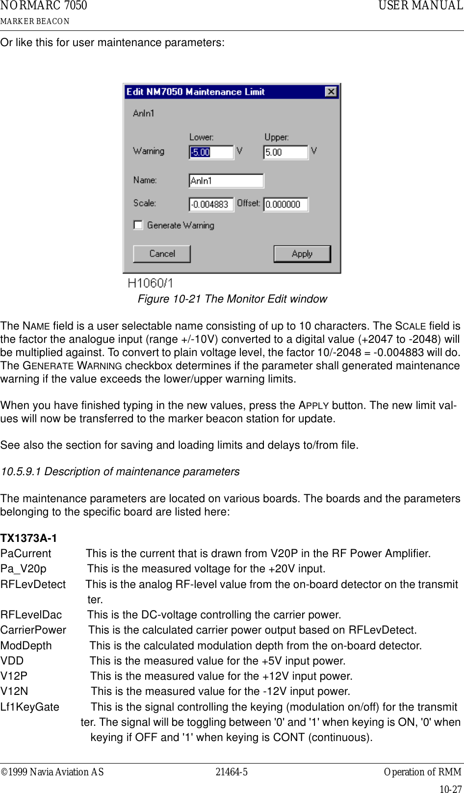
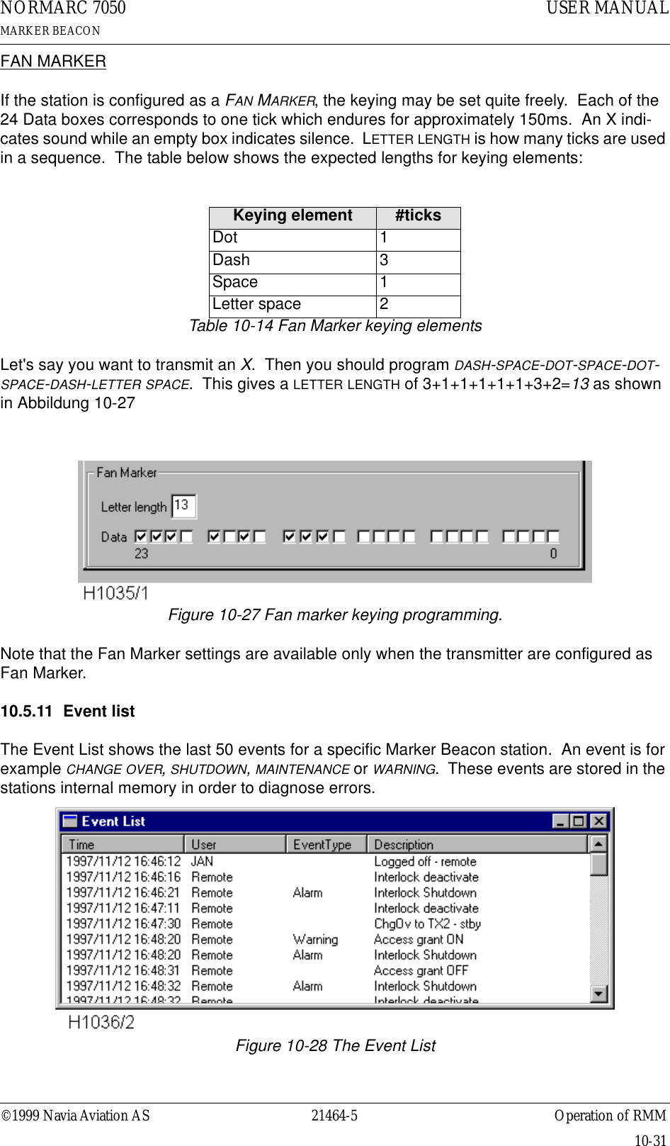
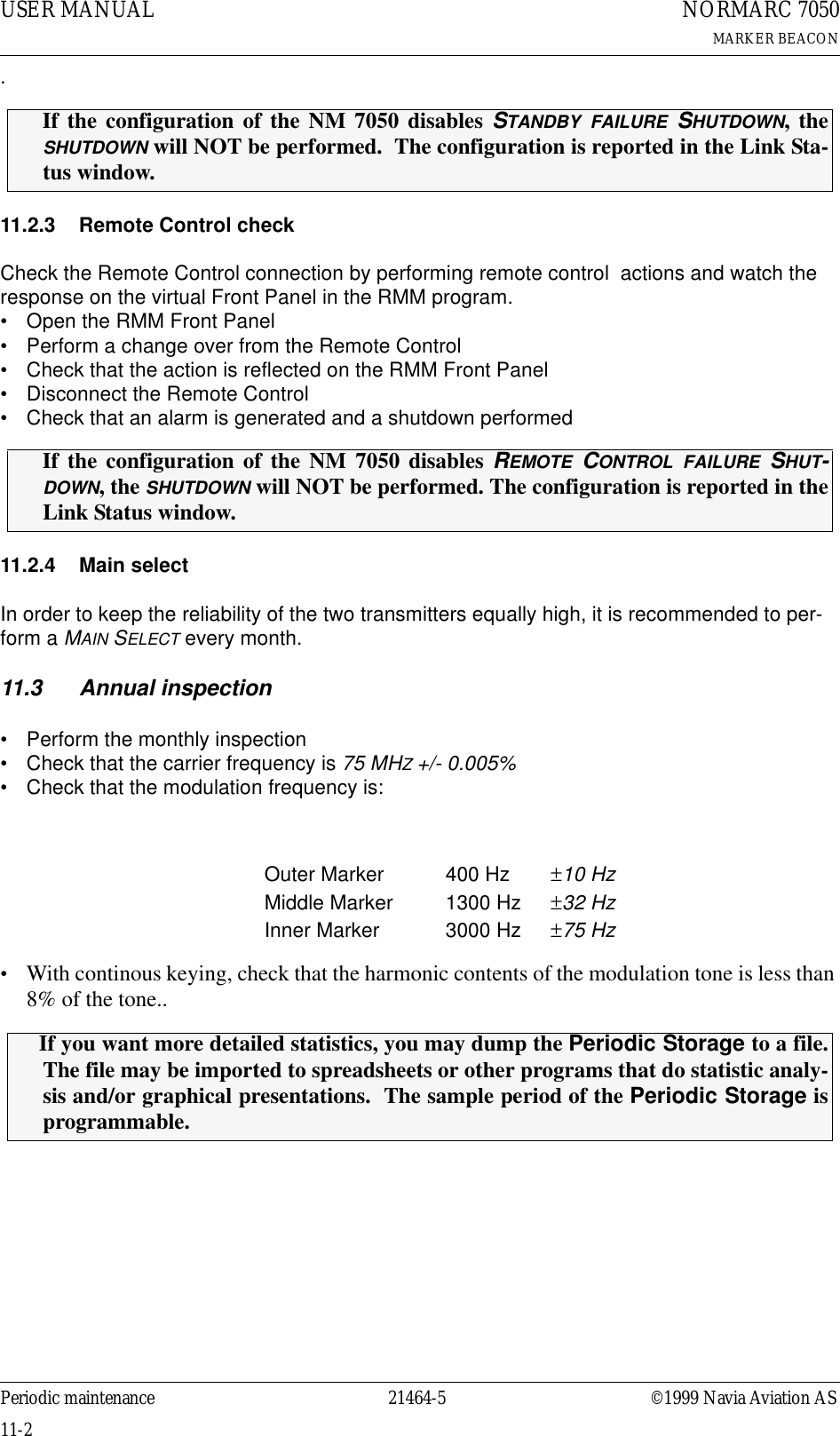
![©1999 Navia Aviation AS 21464-5 Operation Main CabinetUSER MANUALNORMARC 7050MARKER BEACON8-13Figure 8-13 Menu system, Standard MenuTop MenuNormarc- NM7050 -Marker BeaconVer. XMain Menu> Read Syst. Para L1Local Settings L2Syst Settings L3(Leave Access 2/3)Read Syst. Para. &Local Settings &Syst Settings> Mon ParametersTX ConfigurationMaint. val. & lim.System DelaysCommunicationsPassword Menu LEVEL ACCESS 3M MM M(Level 3 access)Local Settings> Reset hist. storageMon. Parameters> M1 RF LevelM1 Mod LevelM1 KeyingM2 RF LevelM2 Mod LevelM2 KeyingTX configuration> TX1 Config TX2 ConfigMaint. val. & lim.> Transmitter 1 OKTransmitter 2 OKPower Supply 1 OKPower Supply 2 OKMonitor 1 OKMonitor 2 OKConn. Interface OKCommunications> Bitrate Local Bitrate Remote Init ModemTX1 config> TX1 Normal Set TX1 Test1 set TX1 Test2 set Change SetSystem delays> Mon1 delay Maint Delay Maint user delayTX1/2 Normal Set> RF Level Mod depth Keying Letter Length Keyer BitsTX1 Test 1/2 set> RF Level Mod depth KeyingChange SetChange tx1/2 set[ Normal ] <ESC>(If selecting "syst settings" while in level 1 or 2)(If selecting "local settings")(If password validated to be OK)Standard MenusNote: Pressing <ESC> on the front panel keyboard takes you up one level in the menu hierarchy. If you are on the top, the <ESC> key takes you to the Main Menu.Note: A dotted line below a menu indicates that there are more submenus availlable for each of the current menu items. Note: Access Level 1 gives readout only Access Level 2 gives readout only except for tx1/2 config. where the user may alter the test settings and changed set (while in level 2/3). Access level 3 gives full edit for all parameters. Note: Menu item "communications" shown only when in access level 3H1121-1](https://usermanual.wiki/Leidos/NORMARC7031.7031-User-Manual/User-Guide-103315-Page-69.png)
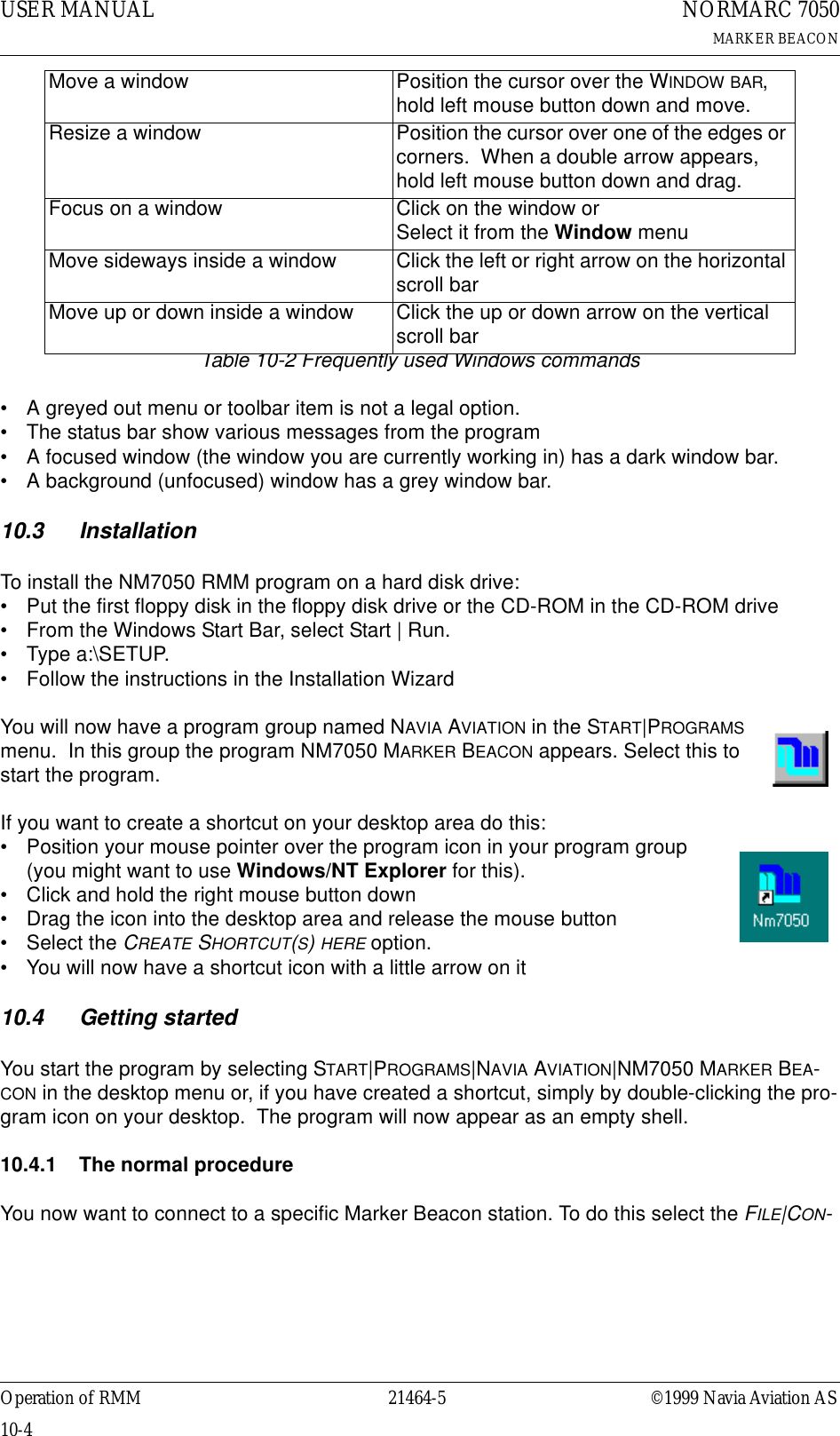
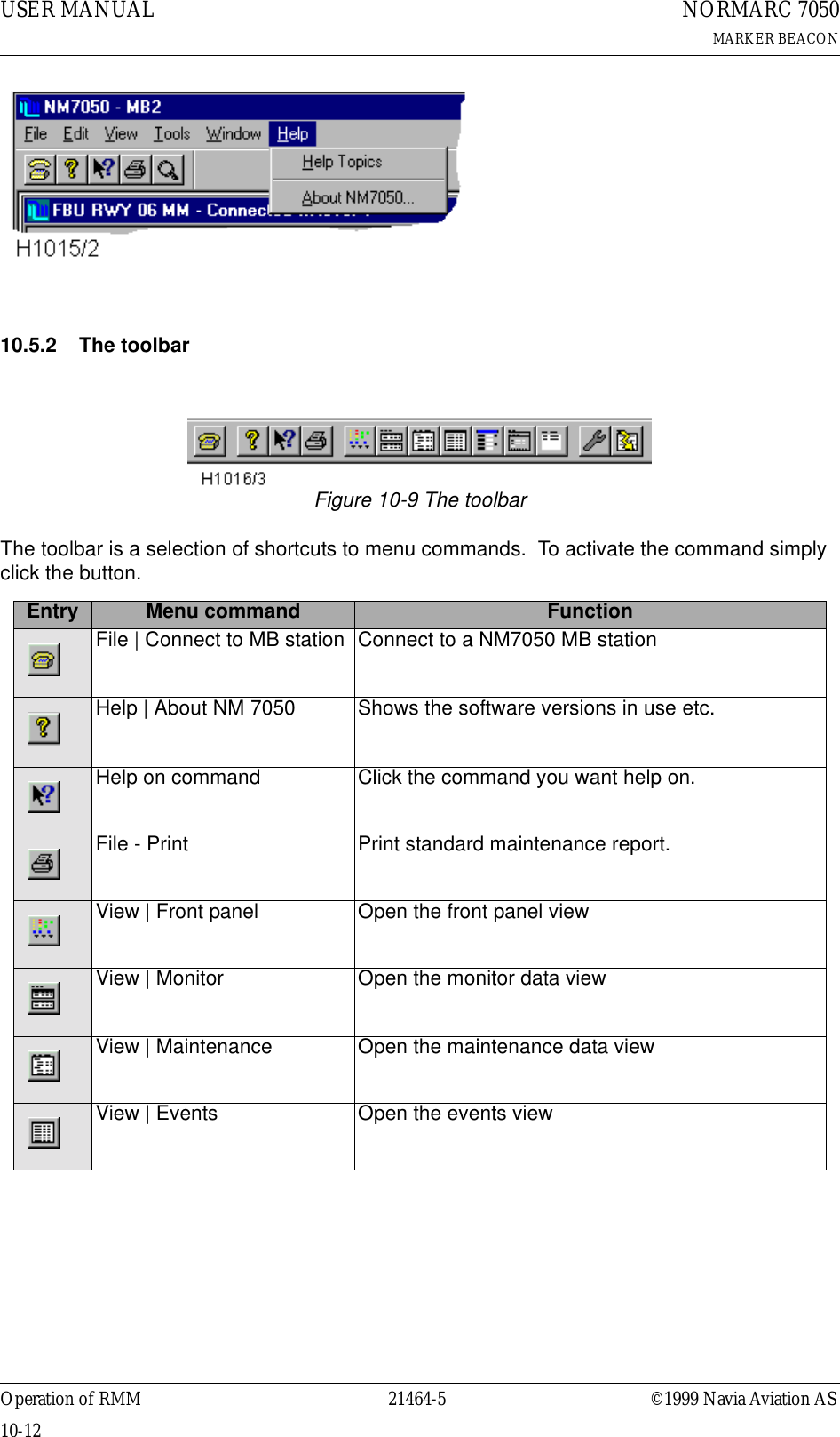
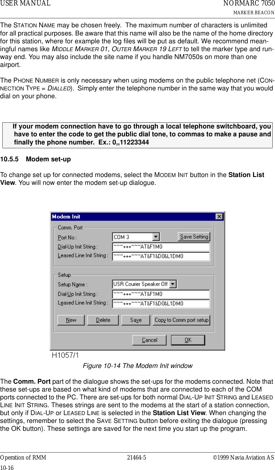
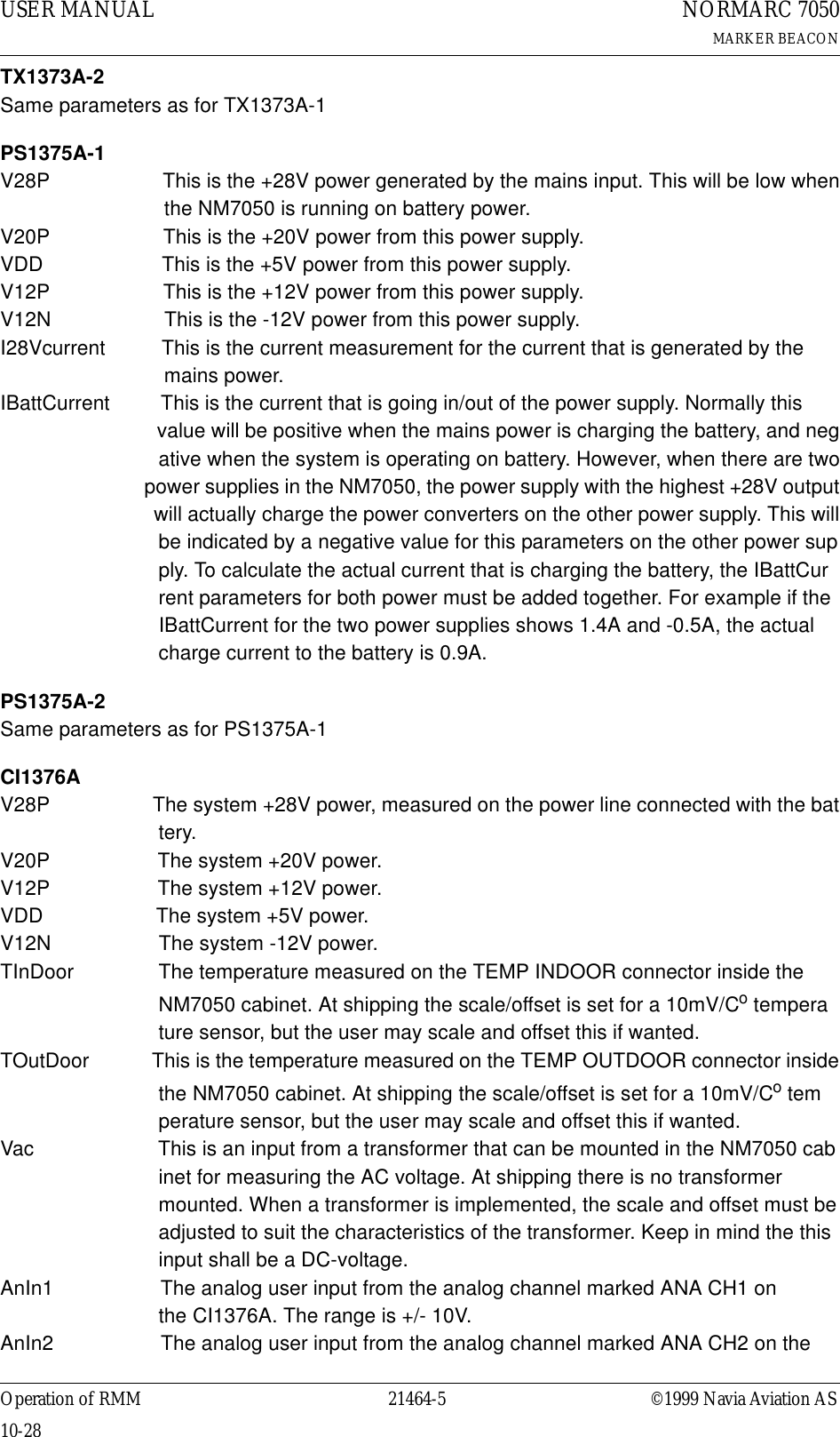
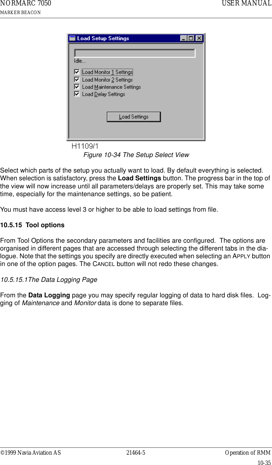
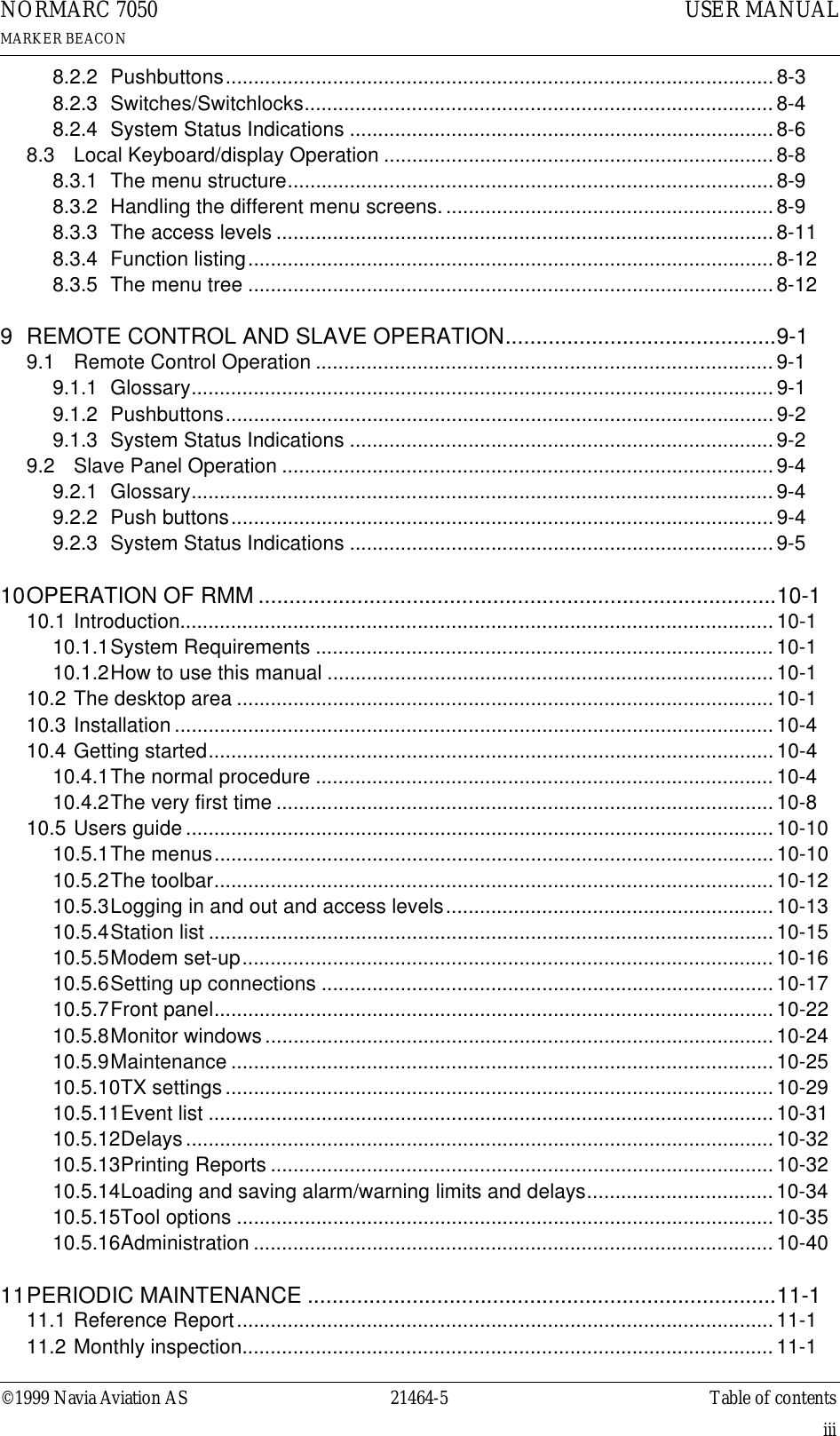
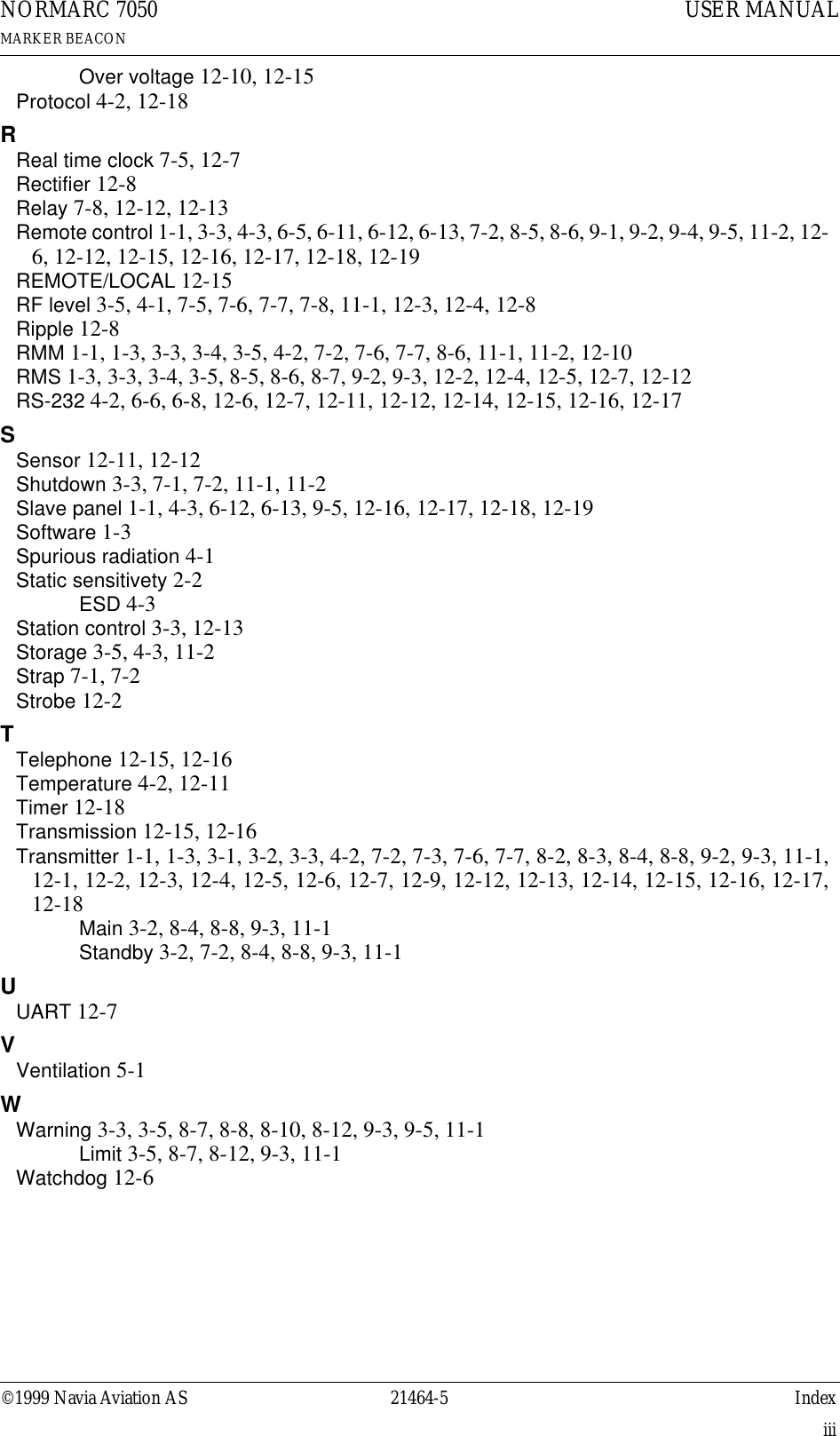
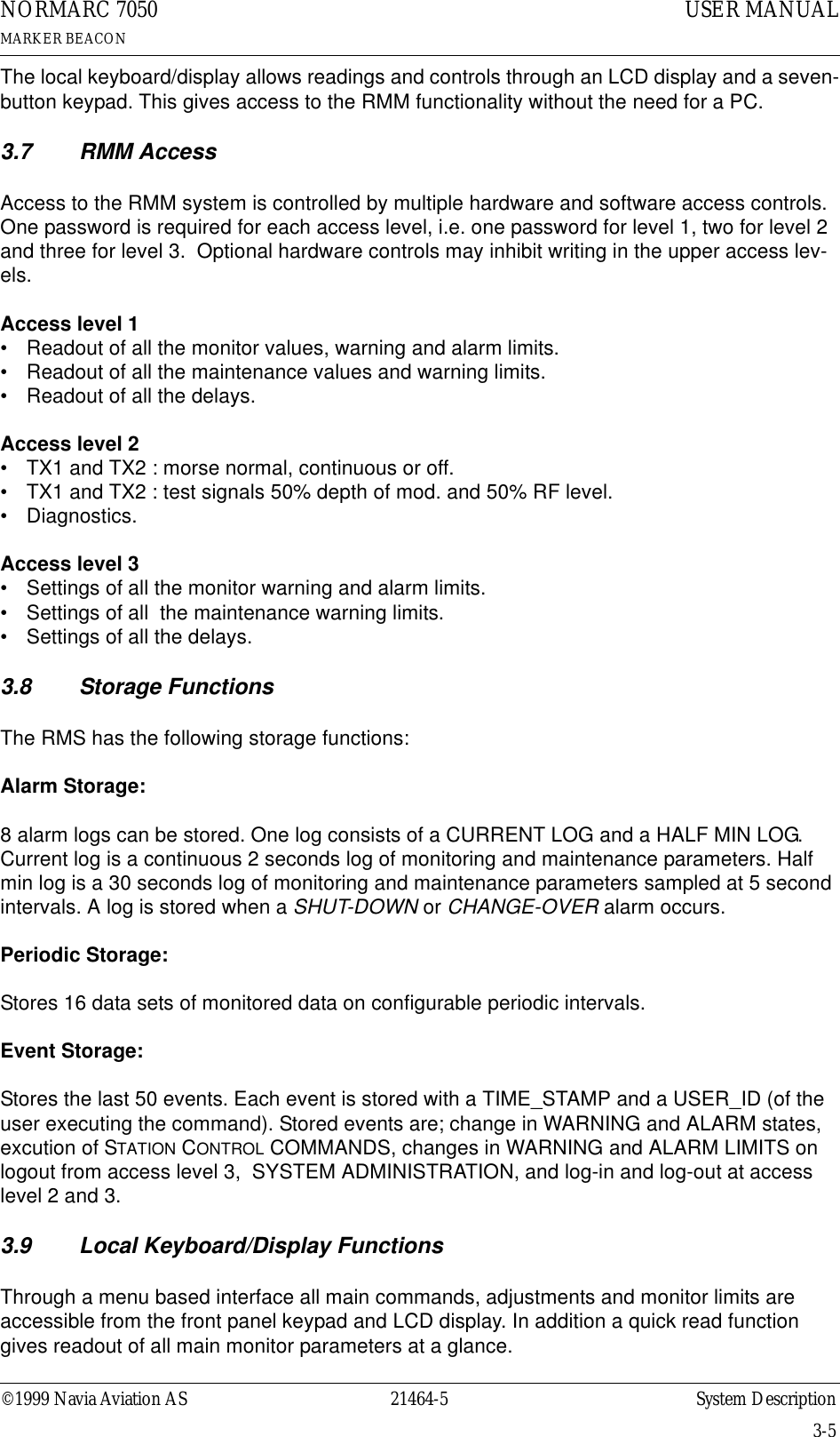
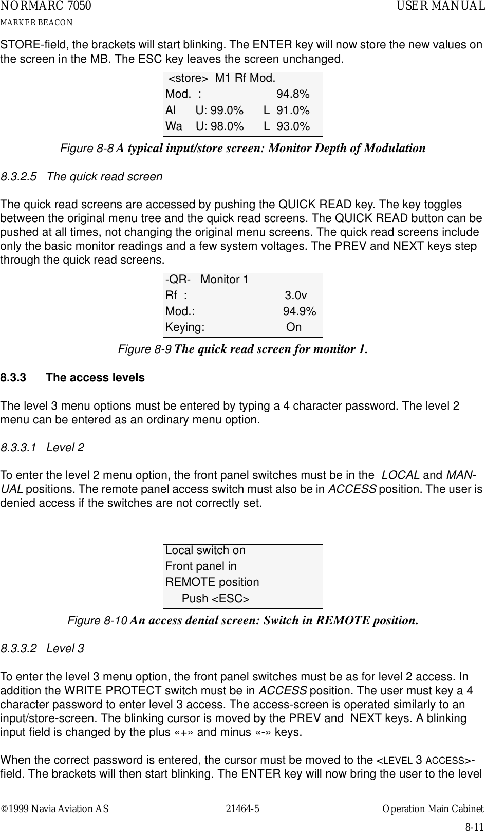
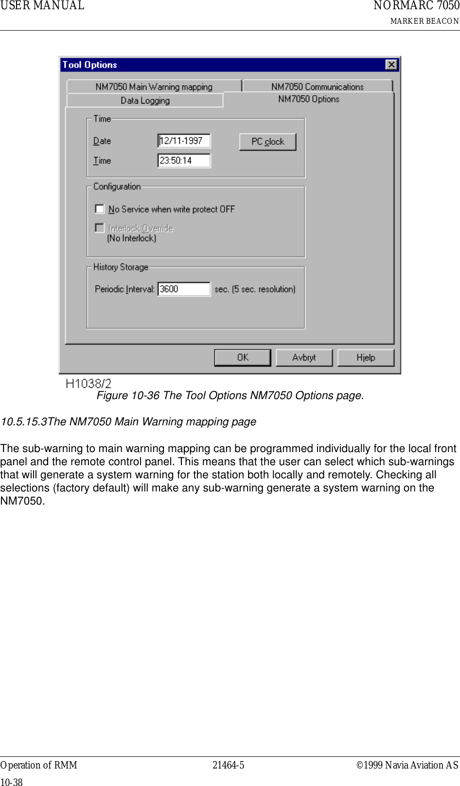
![©1999 Navia Aviation AS 21464-5 Operation of RMMUSER MANUALNORMARC 7050MARKER BEACON10-37figuration (alarm and warning limits).If the Auto filename is checked, the text in the Auto filename format field will be used to gener-ate the filename where the snapshot is placed. If not checked, the user may select a file by a standard file browser. The filename format may contain directly text or codes that will insert the current date/time value according to the following rules:• %YY[YY] The current year is inserted• %M[M] The current month (1-12)• %D[D] The current day (1-31, depending on month and year)• %H[H] The current hour (0-23)• %m[m] The current minute (0-59)• %S[S] The current second (0-59)• %T The current tenth of a second (0-9)For example the string SNAP_%YYYY-%MM-%DD_%HH.%mm.%SS.txtwill give a filename such as SNAP_1998-10-30_14.39.16.txtYou may also select how to separate the elements of the snapshot by selecting in the droplist Delimiter select. This may be useful if special formatting is wanted for exporting to certain pro-grams. You may select between • Spaces Text is formatted for best reading using a standard text editor.• Tabs Tab character is inserted between data elements.• :(Colon) The colon character is inserted between data elements.• ;(Semicolon) The semicolon character is inserted between data elements.10.5.15.2The NM7050 Options pageFrom this page you can change the real time clock in the NM7050. In addition you may config-ure your NM7050 to not set the station in SERVICE condition if the Write Protect switch is turned off. From this dialogue you can also override the interlock if the Local/Remote and Auto/Manual switches are in Local/Manual. This option is only valid when the interlock is active (meaning that the NM7050 is forced off by the interlock switch in the tower). You may also specify the periodic interval for logging of history storage (not implemented in the first ver-sion of the program).• If you press PC CLOCK, DATE and TIME field are filled with the date and time on your PC. The value is loaded into NM7050 when you press the APPLY button. The APPLY button will only be shown when there are changes in the DATE and TIME fields.](https://usermanual.wiki/Leidos/NORMARC7031.7031-User-Manual/User-Guide-103315-Page-113.png)
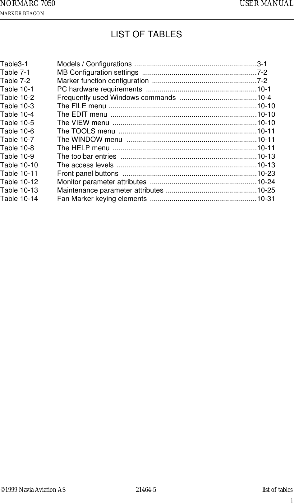
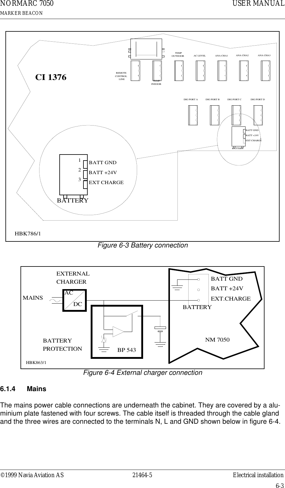
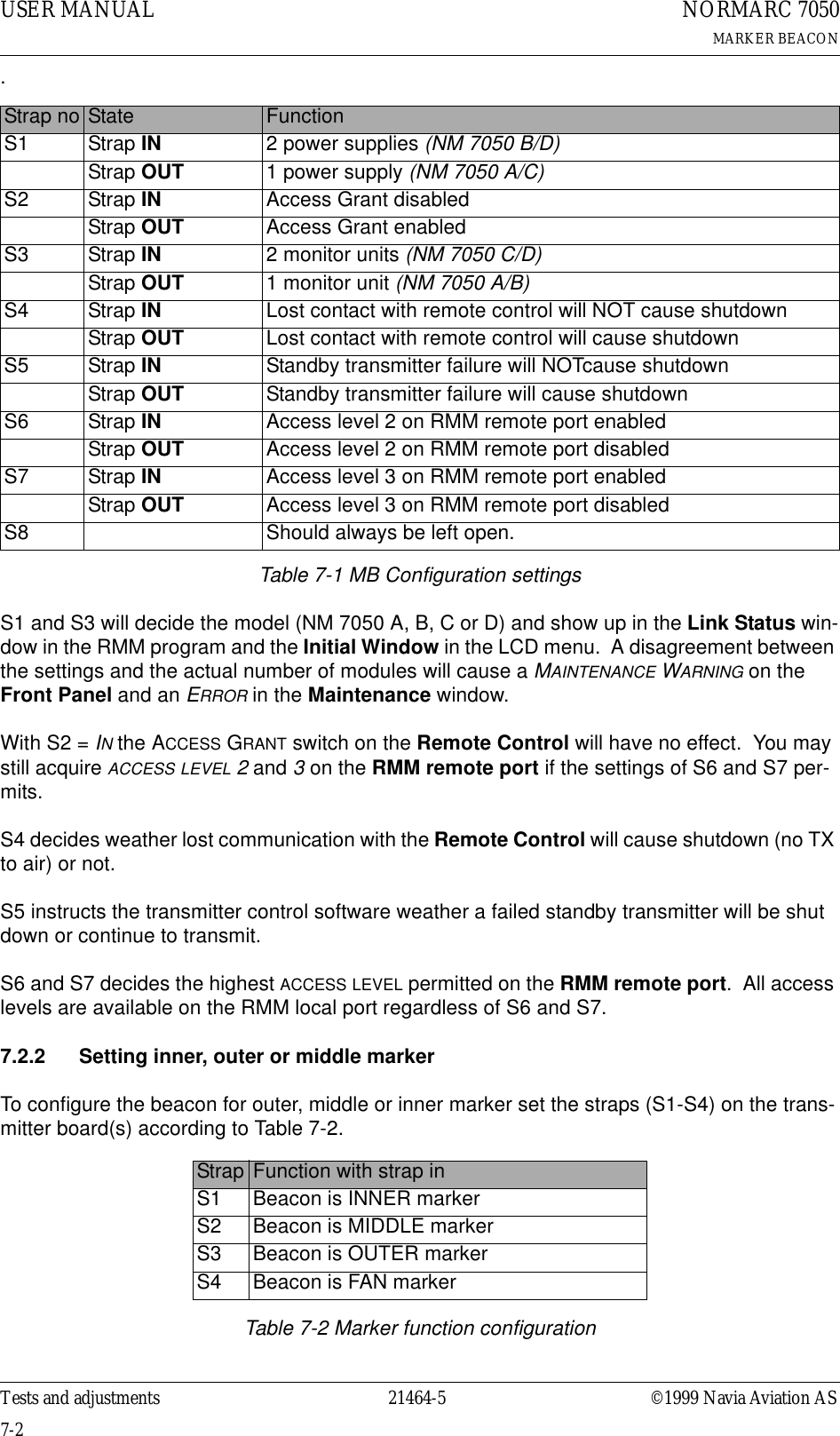
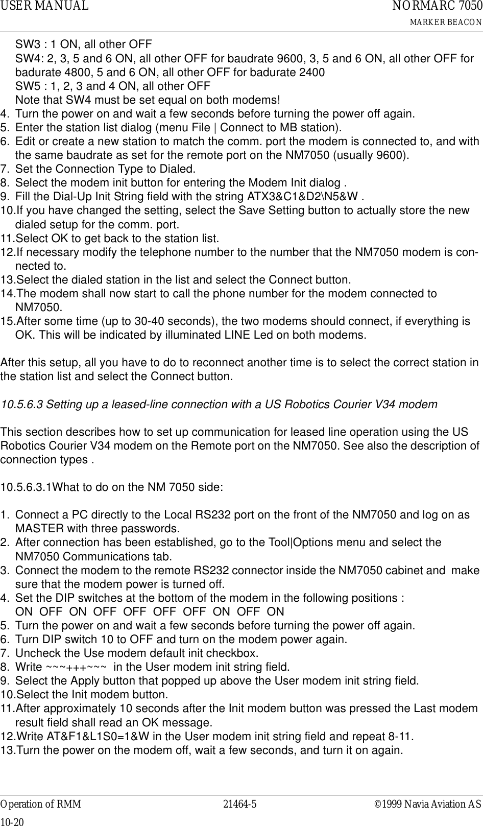
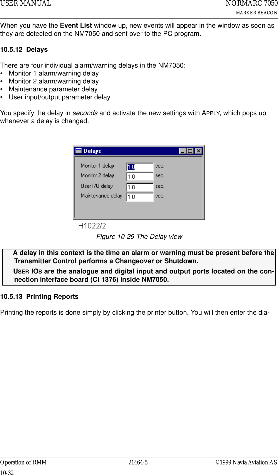
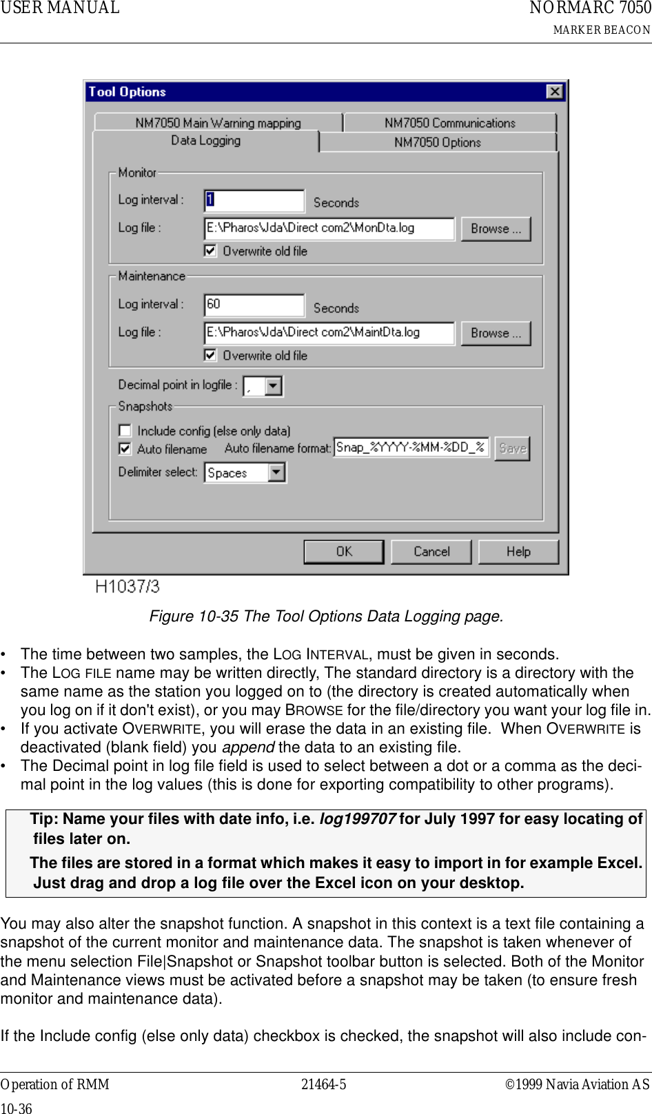
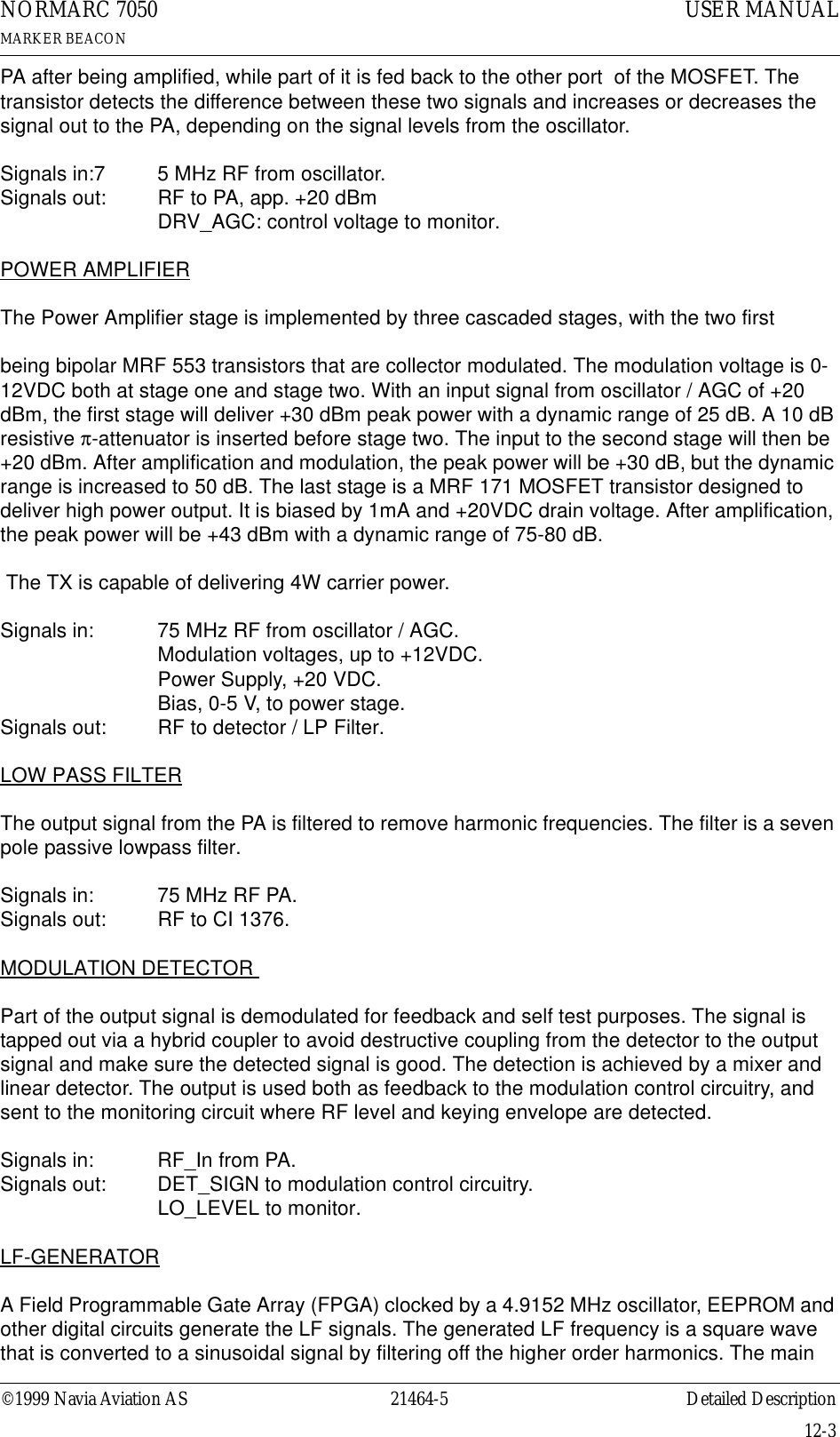
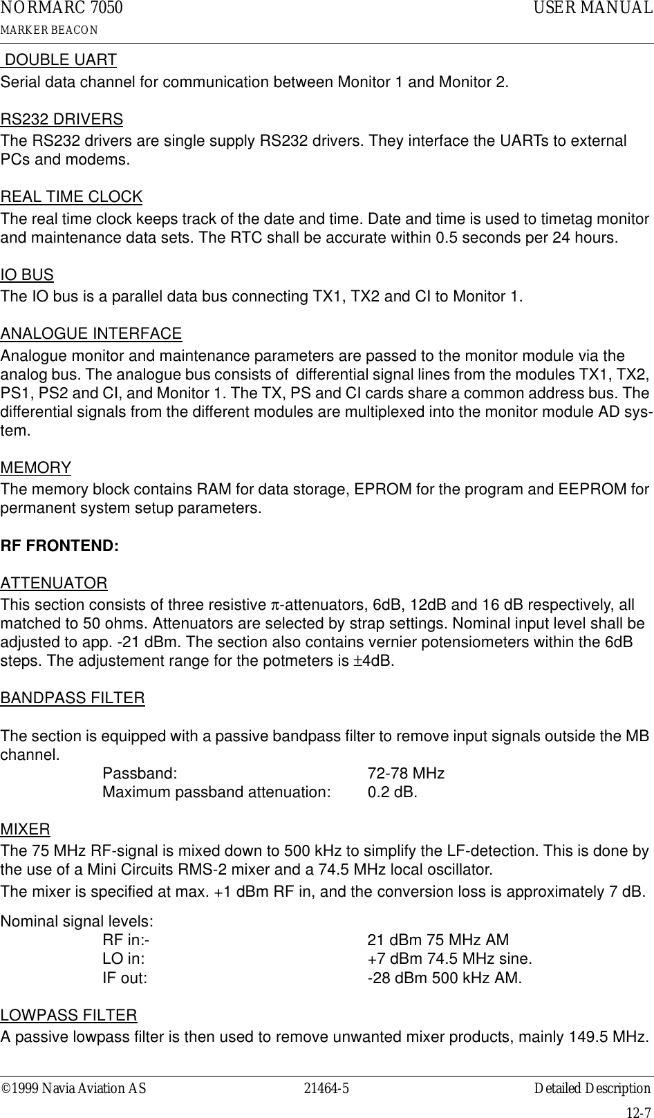
![©1999 Navia Aviation AS 21464-5 Detailed DescriptionUSER MANUALNORMARC 7050MARKER BEACON12-1PART IV DESCRIPTION12 Detailed DescriptionThis chapter describes the modules in detail.12.1 Main Cabinet12.1.1 TX 1373A Transmitter12.1.1.1 General DescriptionTX 1373A is a module designed to transmit Marker Beacon signals. An on board oscillator working at 75 MHz provides an output of app.0 dBm that is used as input to the Power Ampli-fier (PA). The level of this input signal is adjusted to an output of app. +20 dBm. The Power Amplifier is capable of delivering up to 4W carrier power at the cabinet output.Unwanted frequencies are removed by a lowpass filter after the PA. Part of the signal out of the PA is tapped off to be demodulated and used for feedback and self test purposes. Demod-ulation is done by a mixer with a linear detector.The audio signals are generated in the LF circuitry mainly by a Field Programmable Gate Array (FPGA). Inner, Middle or Outer Marker is selected by straps.12.1.1.2 Block diagramFigure 12-1 TX1373 Block diagram12.1.1.3 SignalsOscillatorModulation detectorLP filterPower AmplifierAutomatic Gain ControlRF OUTLF GeneratorMaintenance/MonitorModulation AmpModulation ControlAMUX_A[3:0]DAC_DATA[7:0]DAC_CTRLMODULATION / BIASRF LEVEL / IDENTMAINTENACE SIGNALSDET_SIGNALTXCSTXWRTXRDIOD[7:0]TX_CTRL_BUSTRANSMITTRANSMITRMS_LEV[1:0]A_TX[P,N]HBK817-1](https://usermanual.wiki/Leidos/NORMARC7031.7031-User-Manual/User-Guide-103315-Page-121.png)
![USER MANUAL12-221464-5NORMARC 7050MARKER BEACONDetailed Description ©1999 Navia Aviation AS(See block diagram Figure12-1)12.1.1.4 Building blocks(See block diagram Figure12-1)OSCILLATORThe oscillator is controlled by the Transmit signal from the LF generator. When Transmit is low, a controllable voltage generator turns the internal oscillator 12V voltage on. +12 VDC is then applied to the collector of a bipolar transistor, which is the active device of the oscillator. A 75 MHz crystal is connected in the feedback path together with a resonance circuit.The output signal is amplified to approximately 0 dBm through a RF gain block.Signals in: ON/OFF to switch oscillator on.Signals out: RF to AGCAUTOMATIC GAIN CONTROLThe AGC circuitry is designed to adjust the signal level from the oscillator to the PA. The sig-nal from the oscillator is fed to one of the ports of a dual gate MOSFET. The signal enters the In From DescriptionIOD[7:0] MO 1374 Parellel data bus for communication between TX 1/2, CI and MO1~TXCS MO 1374 Transmitter card select~TXWR MO 1374 Write strobe for IO bus~TXRD MO 1374 Read strobe for IO busTX_ADR CI 1376 Transmitter selectTX_ON MO 1374 Transmitter on/offAMUX_A[3:0] MO 1374 Used to select measurement~RMS_LEV[1:0] MO 1374 Signals access level for RMS Out In DescriptionRF_OUT Antenna Radio signal∼TX_FB MO 1374 Signal tells monitor that transmitter is activeA_TX[P,N] RMS RMS analogue test signals∼TXCSB MO 1374 Transmitter card select backBidirectional To/From DescriptionTX_CTRL_BUS MO 1374 Changeover Control (TX_ADR), transmitter on/off (TX_ON), card select back (TXCSB), feed back (TX1/2_FB)Power in From DescriptionV20P PS 1375 +20 VDC to PAV12P PS 1375 +12 VDCVDD PS 1375 +5 VDCGND PS 1375 Analogue groundV12N PS 1375 -12 VDC](https://usermanual.wiki/Leidos/NORMARC7031.7031-User-Manual/User-Guide-103315-Page-122.png)
![USER MANUAL12-421464-5NORMARC 7050MARKER BEACONDetailed Description ©1999 Navia Aviation ASinputs to the FPGA are the strapped signals used to select outer, middle, inner or FAN marker frequency, as well as status signals regarding oscillator, RF- and LF-level output. Communi-cation with the FPGA is done by the IOD[7:0], ~TXRD and ~TXWR signals. Multiplying DAC’s are used to adjust RF level and modulation depth. The keyed LF signal and the RF level is applied to the Modulation Control Circuits. The modulation voltages to the PA is generated by the use of these signals as well as the ON/OFF signal from the AGC and the detected signal from the PA. MAINTENANCE / MONITOR CIRCUITRYThe purpose of the onboard monitor circuitry is to give the Monitor card MO 1374 information about the status of the transmitter. The AMUX_ADR[3:0] from the MO 1374 is applied to the analogue multiplexer. These four lines select one of sixteen possible signals to be measured.The signals measured are:• PA 20 VDC supply voltage• PA current drain @ 20 VDC• Detected RF level from demodulator• Keying envelope from demodulator• Positive/negative modulation peaks• LF AGC voltage• Driver AGC voltage• RF level DC voltage from LF generator• Supply voltage statusThe signal information is sent to the MO 1374 monitor unit as a differential analogue test sig-nal from the MUX.12.1.2 MO1374 Monitor12.1.2.1 General descriptionThe MO1374 monitor is a microprocessor based module. It contains the MB software and forms the basis of the monitor, transmitter control, system maintenance handling and RMS user interface.The MO1374 consists of two submodules:The CPU section includes; CPU, memory, communication ports and an AD converter system.The RF frontend receives a recombined 75MHz AM monitor signal with modulation frequency of 400, 1300 or 3000 Hz, from one or two antennas. This signal is conditioned, mixed and demodulated to produce the output parameters; RF level, modulation level and keying enve-lope. These parameters are monitored by the CPU section.](https://usermanual.wiki/Leidos/NORMARC7031.7031-User-Manual/User-Guide-103315-Page-124.png)
![©1999 Navia Aviation AS 21464-5 Detailed DescriptionUSER MANUALNORMARC 7050MARKER BEACON12-512.1.2.2 Block diagramFigure 12-2 MO 1374 block diagram12.1.2.3 Signals(See block diagram Figure12-2)TO BACKPLANE::In From DescriptionRF_IN Antenna RF from antennaA_TX1/2[P,N] TX 1373 Analogue input from transmittersA_PS1/2[P,N] PS 1375 Analogue input from power suppliesA_CI[P,N] CI 1376 Analogue input from Connection InterfaceTX1/2_FB TX 1373 Feedback from transmittersOut To Description∼RMS_LEV[1:0] RMS Access levelAMUX_A[3:0] TX 1373 PS 1375 Address signals for differential analogue signal busIO_CTRL_BUS TX 1373, CI 1376 Control signals for IOD[7:0]75MHz BandpassFilter0.5 MHzLow passFilter74.5 MHz Local Oscillator MixerAttenuator Amplifier Modulation detectorEnvelope detectorRF-detektor+_Lowpass filterKeying EnvelopeLF-leve lRF level+-InterruptsJumperCPUCTRLportDoubleUARTAnalogMUXAnalogMUXCTRLportADMO1374Watchdog 1.Battery RESET MemoryRAMEPROMEEPROMReal timeclockRS232& FSKdriversDual 8:1CTRLportIOD[7:0]LCD_DATA[7:0]LC_KEY[7:0]LC_LED[14:0]MON_RXD/TXDCPU SECTIONRF FRONTENDDiff. ampKB[7:0]LC_CTRL_BUSIO_CTRL_BUSAMUX_A[3:0]RF INA_XX_[P,N]Keying EnvelopeBattery pwr.Watchdog 2RS232driverLOCAL_SER_BUSREM_SER_BUSRC_SER_BUSTX_CTRL_BUSHBK818/1](https://usermanual.wiki/Leidos/NORMARC7031.7031-User-Manual/User-Guide-103315-Page-125.png)
![USER MANUAL12-621464-5NORMARC 7050MARKER BEACONDetailed Description ©1999 Navia Aviation ASTO FRONTPLANE:12.1.2.4 Building blocks(See block diagram Figure12-2)CPU SECTION:CPUThe CPU is an 80C188EB micro controller. Included in the CPU is an address decoding unit and two UARTs. Both of these UARTs are used for serial communication. The operating fre-quency of the CPU is 20MHz. This requires a 40MHz oscillator because of the internal divide by two circuit.WATCHDOG AND BATTERYThe watchdogs resets the CPU:• at power up• if the CPU does not toggle the watchdog reset bit at less than approx. 1.6 sec. intervals When the +5V supply voltage goes below the battery voltage, battery voltage is passed through to the RAM and real time clock. The battery voltage is measured through an optocou-pler switch in order to keep the battery life time high. The battery lifetime is approximately one month with continuous use (system power turned off).INTERRUPTS4 of the CPU's 5 interrupt lines are utilised for serial communication and AD conversion.Bidirectional To/From DescriptionIOD[7:0] TX 1373, CI 1376 Parallel data bus for communication between TX ½, CI and MO1RC SER BUS Remote Control FSK and RS232 lines to remote controlREM SER BUS Remote PC RS232 line to remote PCMON_RXD/TXD Other monitor Serial data channelIn From DescriptionLC_KEY[7:0] LC 1377 Local control panel pushbuttons/switchesKB[7:0] LC 1377 Local keyboard inputsOut To DescriptionLCD_DATA[7:0] LC 1377 data bus to LCD LCD_* LC 1377 Control strobes for LCD_DATA[7:0]LC_LED[14:0] LC 1377 Led indicatorsBidirectional To/From DescriptionTX_CTRL_BUS TX 1373 Changeover Control (TX_ADR), transmitter on/off (TX_ON), card select back (TXCSB), feed back (TX1/2_FB)LOCAL SER BUS Local PC RS232 line to local PC](https://usermanual.wiki/Leidos/NORMARC7031.7031-User-Manual/User-Guide-103315-Page-126.png)
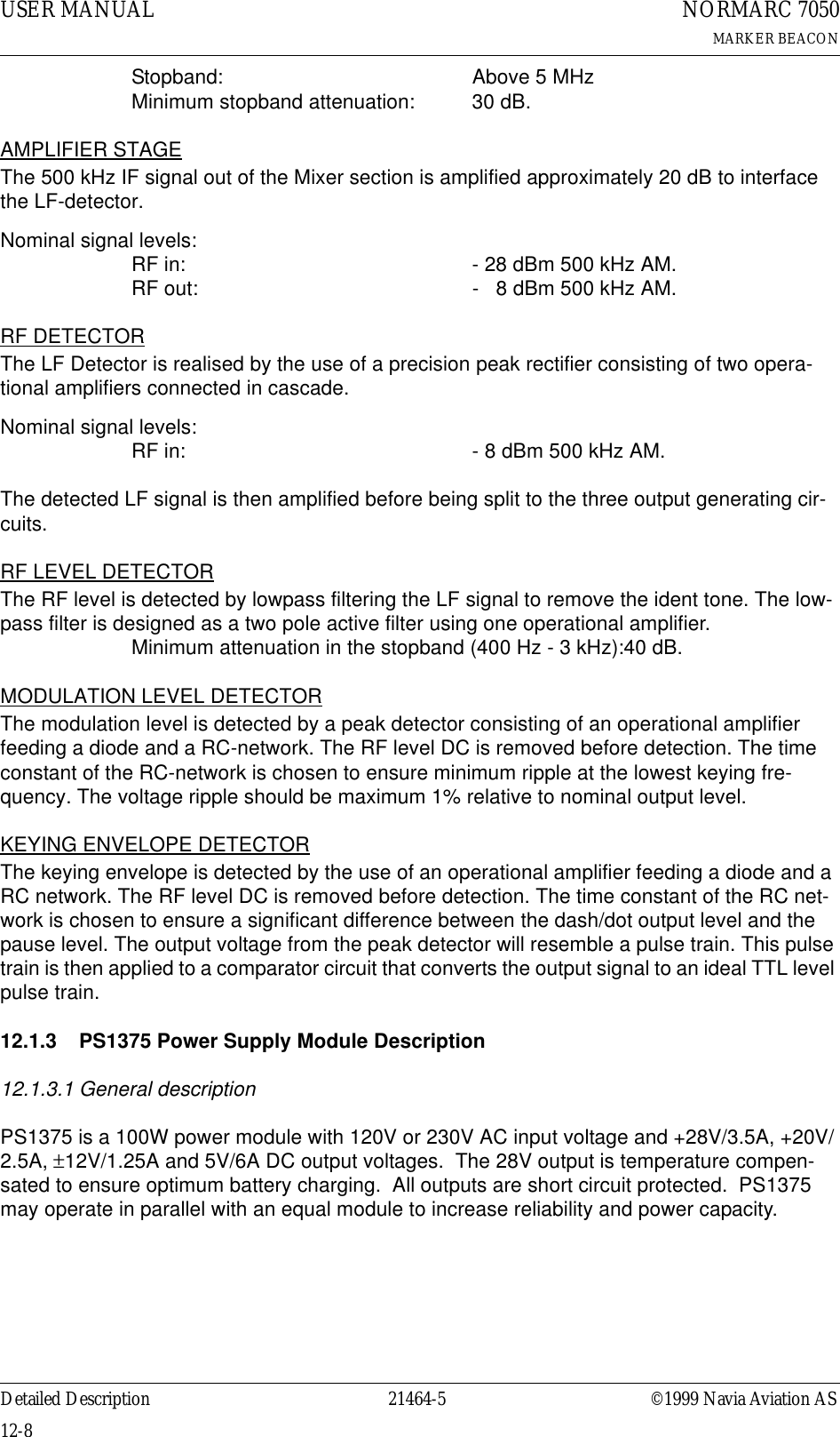
![©1999 Navia Aviation AS 21464-5 Detailed DescriptionUSER MANUALNORMARC 7050MARKER BEACON12-912.1.3.2 Block diagramFigure 12-3 PS 1375 block diagram.12.1.3.3 Signals(See block diagram Figure12-3)12.1.3.4 Functional description (See block diagram Figure12-3)In From DescriptionVAC[L,N] Manis ACAC_GND Mains GroundAMUX_A[2:0] MO 1374 Address signals for differential analogue signal busOut To DescriptionV28P Battery charger voltage and primary DC voltage 28VV20P TX 1373 DC voltage to transmitter section 20VDCV12P System DC voltage +12VV12N System DC voltage -12VVDD System voltage to digital partsA_PS_[P,N] Multiplexed maintenance signalsSYNC Frequency syncronisation between power mod-ulesDCDCDCDCDCVA AVVVVVACLVACNACGNDV20PV20P_MEASV15PV15P_MEASV15NV15N_MEASVDDVDD_MEASIBATT_MEASV28PV28P_MEASI28P_MEASGNDDCAMUX_A[2:0]A_PS_[P,N]SYNCSIGN_IBATTSIGN_I28PHBK819/1](https://usermanual.wiki/Leidos/NORMARC7031.7031-User-Manual/User-Guide-103315-Page-129.png)
![USER MANUAL12-1021464-5NORMARC 7050MARKER BEACONDetailed Description ©1999 Navia Aviation ASThe mains input is fused and filtered before it is rectified and smoothed. The first DC/DC con-verter generates 28VDC output which is filtered in the next block. The filter output serves as both battery charger and input to the +20V, ±12V and +5V DC/DC converters. V28P is tem-perature compensated to give 26.4V at 50°C, linearly increasing to 29.6V at -30°C.The voltage (V28P) from either the AC/DC section or the battery is passed through an on/off switch and separate fuses to the secondary DC/DC converters. Here +20V, ±12V and 5V are created in one single and one triple output DC/DC converter. All outputs are lowpass filtered in LC filters.The or'ing diodes on the DC outputs makes parallel coupling possible. All RMM voltage mea-surements are done prior to these diodes to make fault tracking possible. All RMM measure-ments are multiplexed into A_PS_[P,N] by the AMUX_A[2:0] signals.The RMM measurements are:12.1.4 CI1376/PB1378 Connection Interface Module Description12.1.4.1 General descriptionCI 1376 is the electrical backplane of NM 7050. The module has four functions:• External connections interface with over voltage protection.• Motherboard for all plug-in boards.• Transmitter change over.• Battery protection against deep dischargeSignal MeasurementI28P_MEAS Total current in V28PPIBATT_MEAS Battery current in V28PSIGN_I28P Charge/discharge info to theSIGN_IBATT current measurements aboveV*_MEAS Voltage in corresponding V*](https://usermanual.wiki/Leidos/NORMARC7031.7031-User-Manual/User-Guide-103315-Page-130.png)
![©1999 Navia Aviation AS 21464-5 Detailed DescriptionUSER MANUALNORMARC 7050MARKER BEACON12-1112.1.4.2 Block diagramFigure 12-4 Connection Interface block diagram12.1.4.3 Signals(See block diagram Figure12-4)For plug in board signals see the specifications for each board..External DescriptionREM_* Remote PC RS232 interfaceRC_LINE[A,B] Remote control FSK modem interface (serial I/F bus)RC_[TXD,RXD] Remote control RS232 interface (serial I/F bus)VAC[P,N] AC voltage input (50-60Hz)T[OUT,IN]DOOR Temperature sensor inputANLG[3:1][P,N] Differential analogue DC inputDIGIN[5:0] Digital inputs (TTL level)DIGOUT[1:0] Digital outputs (TTL level)V28P +28V DC input in case of external battery chargerV28P_PROT Battery input/output, disconnected if voltage drops below 22VPS1 PS2MO2 MO1TX1 TX2REM_* RC_*VAC[P,N]T[OUT,IN]DOORANLG[3:1][P,N]DIGIN[5:0]AUX_RI_IN[1:0]DIGOUT[1:0]AUX_RI_OUT[3:0]RF_OUTRF_TX1 RF_TX2V28P V28P_PROTVrefIOD[7:0]Control busA_CI_[P,N]Serial I/FPowerGQDQDMotherboardBattery ProtectionExternal ConnectionsChange OverCI_WR~CI_RD OEAMUX_A[3:0]Dummy loadTX_TO_AIRQD~CFG_RD OEConfigPlatformHBK828/1](https://usermanual.wiki/Leidos/NORMARC7031.7031-User-Manual/User-Guide-103315-Page-131.png)
![USER MANUAL12-1221464-5NORMARC 7050MARKER BEACONDetailed Description ©1999 Navia Aviation ASCONTROL SIGNALS:INTERNAL DATA PATHSIOD[7:0] RMS databus to and from MO1374A_CI_[P,N] Differential analogue maintenance signal to MO1374V28P, V20P,V12[P,N],VDD" Power" bus from PS137512.1.4.4 Building Blocks (See block diagram Figure12-4)EXTERNAL CONNECTIONSCI 1376 contains overvoltage protected interfaces to the following external connections:• One marker Beacon antenna• One backup battery (or external battery charger)• One PC (RS232 direct or via modem)• One Remote control (via FSK modem or RS232)• Two temperature sensors• Three differential analogue DC channels• One mains voltage sensor (transformer)• Six digital inputs• Two digital outputsIn addition, measurement on all power voltages are multiplexed into the analogue mainte-nance bus. Two auxiliary inputs and four auxiliary outputs are connected to the RMS parallel bus (IOD). System configuration is transferred from a strap platform to the RMS-system over the IOD bus.MOTHERBOARD Transmitter From DescriptionRF_TX[1:2] TX 1373 50 ohms RF inputRF_OUT Change over relay 50 ohms RF outputTX_TO_AIR MO 1374 Controls which transmitter is connected to antenna (change over)AMUX_A[3:0] Controls which analogue maintenance signal that is connected to A_CI_[P,N]CI_WR Controls writing from the IOD bus to DIGOUT[1:0] external output and AUX_RI_OUT[3:0] auxiliary remote control outputs.~CI_RD Controls reading from DIGIN[5:0] external input to the IOD bus and AUX_RI_IN[1:0] auxiliary remote control inputs.~CFG_RD Controls reading from the system configuration platform to the IOD bus](https://usermanual.wiki/Leidos/NORMARC7031.7031-User-Manual/User-Guide-103315-Page-132.png)
![©1999 Navia Aviation AS 21464-5 Detailed DescriptionUSER MANUALNORMARC 7050MARKER BEACON12-13CI1376 performs interconnections between two TX1373 transmitters (TX1 and TX2), two MO1374 monitors (MO1 and MO2) and two PS1375 power supplies (PS1 and PS2) and the external connectors.TRANSMITTER CHANGE OVERThe TX_TO_AIR signal (driven by the station control software in MO1374) controls which transmitter is connected to the antenna and which is connected to the dummy load. The change over function is performed by an RF relay and the dummy load is a suitable 50Ω resis-tor.BATTERY PROTECTIONA voltage comparator compares the V28P signal (on the PS1375 side) to a reference voltage. If V28P drops below 22V, the comparator disconnects the battery (V28P_PROT). The battery is reconnected when V28P exceeds 22V. If external chargers are used (to extend battery backup time) an external battery protection circuit has to be used and the CI1376 protection circuit is bypassed.12.1.5 LC 1377 Local Control and Display/Keyboard Interface12.1.5.1 General descriptionLC1377 is an interface card between MO1374 (monitor/TX control w/CPU) and the man/machine interface (local control pushbuttons/LEDs and LCD/keyboard pushbuttons) of the Marker Beacon.12.1.5.2 Block DiagramFigure 12-5 LC 1377 block diagramLCDw/KEYBOARDLOCAL CONTROLSTATUS LEDsLOCAL CONTROLPUSH BUTTONSAND SWITCHESRS232CONNECTORTO LOCAL PCLCDCONTRASTADJUSTMENT388815LC_CTRL_BUSLCD_DATA[7:0]KB[7:0]V12NVDDGNDLC_LED[14:0]LC_KEY[7:0]LOCAL_TXDLOCAL_RXDLOCAL_RTSLOCAL_CTSHBK820/1](https://usermanual.wiki/Leidos/NORMARC7031.7031-User-Manual/User-Guide-103315-Page-133.png)
![USER MANUAL12-1421464-5NORMARC 7050MARKER BEACONDetailed Description ©1999 Navia Aviation AS12.1.5.3 Signals12.1.5.4 Building Blocks (See block diagram Figure12-5)LEDSThe LEDs on the LC1377 are driven by LED driver input signals. The LED anodes are con-nected to VDD and the cathodes are connected to LED driver inputs. The LED driver circuits (outside LC1377) contains the resistors for correct LED illumination currents. LED status indi-cations includes :•System Alarm•System Warning•System Service•System Normal• Main select = TX1• Main select = TX2•TX to air = TX1•TX to air = TX2• TX1 on/off status• TX2 on/off status• Standby TX on air Warning• Parameter Warning•Battery Warning• Monitor disagree Warning• Maintenance WarningLOCAL CONTROL PUSHBUTTONS/SWITCHESThe local control pushbutton/switch outputs are normally open. One side of the pushbutton/switch is connected to ground while the other is connected to the output line. Pushbutton func-tions include:• ON/OFF key• CHANGEOVER key• MAIN SELECT keyIN From DescriptionLC_LED[14:0] MO 1374 LED driver inputs LCD_DATA[7:0] Data input to LCDLCD_RW LCD R/W select for LCD interfaceLCD_RS LCD register select trobeLCD_ENA LCD enableV12N -12VDC system voltageVDD PS 1375 +5 VDC system voltageGND Ciruit groundOut To DescriptionLC_KEY[7:0] MO 1374 Local control push buttons and switchesKB[7:0] MO 1374 Keyboard push buttonsBidirectional To/From DescriptionLOCAL_* Local PC RS 232 to local PC](https://usermanual.wiki/Leidos/NORMARC7031.7031-User-Manual/User-Guide-103315-Page-134.png)
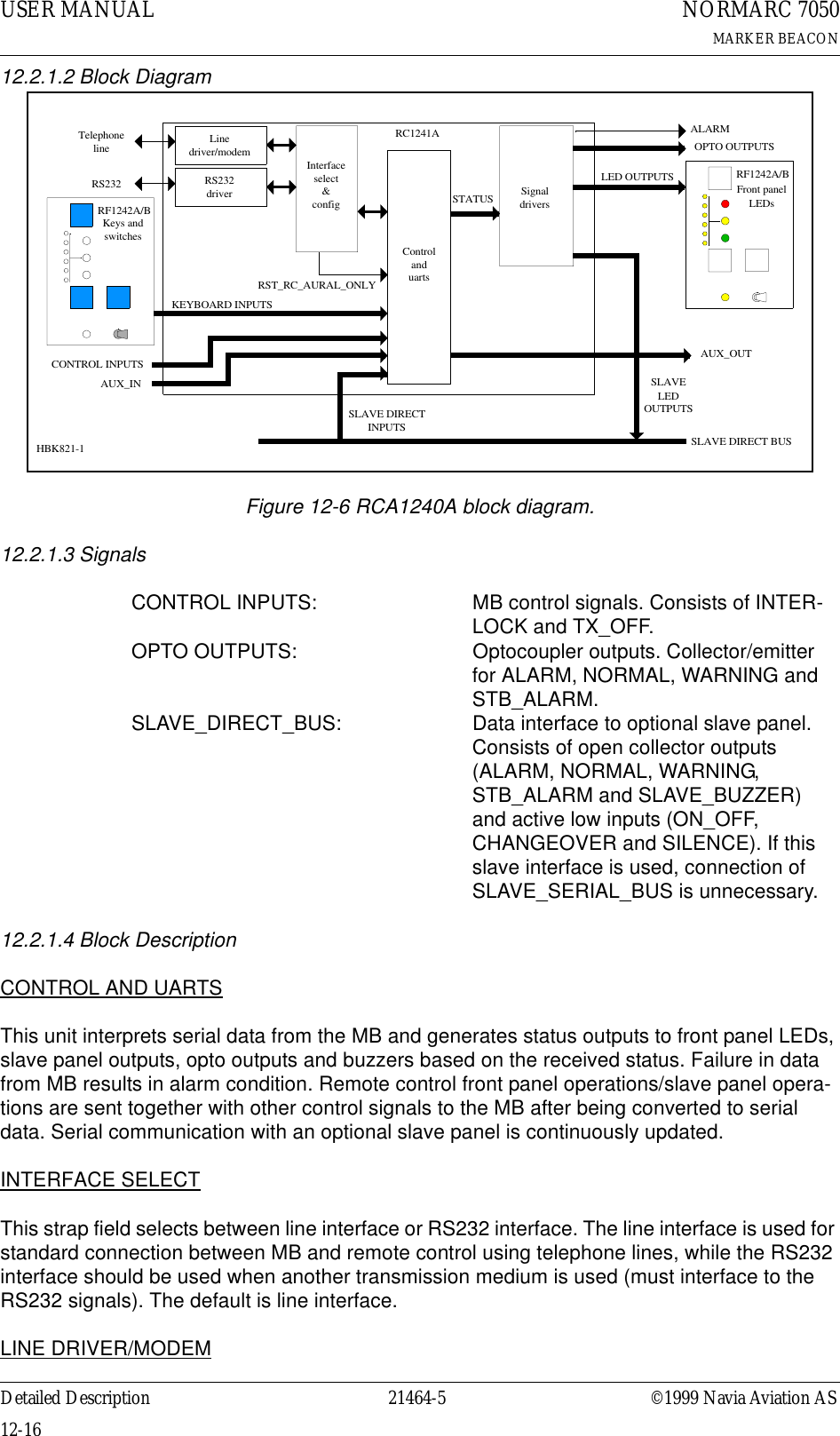
![©1999 Navia Aviation AS 21464-5 Detailed DescriptionUSER MANUALNORMARC 7050MARKER BEACON12-15• TX1 ON/OFF key• TX2 ON/OFF key• AUTO/MANUAL switch• REMOTE/LOCAL switch• WRITE PROTECT switchLCD KEYBOARDThe LCD keyboard pushbuttons functions in the same way as the local control pushbuttons, except for the functionality :• ESCAPE• NEXT• PREVIOUS•ENTER•PLUS• MINUS• QUICK READLCDThe LCD is controlled by the LCD_DATA[7:0], LCD_RW, LCD_RS and LCD_ENA. These sig-nals are directly connected to the LCD.LCD contrast can be adjusted by means of a potentiometer. Adjust the potentiometer until the LCD can be read clearly. The adjustable voltage is between -8.5V and +5V.RS232 TO LOCAL PCThe RS232 interface to the local PC includes TxD, RxD, RTS and CTS. The RS232 lines has over voltage protection.12.2 Tower Equipment12.2.1 Remote Control Assembly12.2.1.1 General DescriptionThe RCA1240A remote control assembly consists of the remote control RC1241A and front panel RF1242A, and provides the user interface to the MB from the control tower, or technical equipment room. The RCA1240A connects to the MB either by using ordinary telephone lines, or by an optional transmission medium using the RS232 signals. The selection between these two interfaces are done by means of straps on the RC1241A.The line interface is using the V.21 standard (300 baud FSK) for use with ordinary 2-wire 600 ohm telephone line. The transmitter level is -10 dBm, and the receivers dynamic range is from -10 dBm to -34 dBm.](https://usermanual.wiki/Leidos/NORMARC7031.7031-User-Manual/User-Guide-103315-Page-135.png)