Contents
7031 User Manual

©1999 Navia Aviation AS
NORMARC 7050
MARKER BEACON
User Manual
21464-5

©1999 Navia Aviation AS

©1999 Navia Aviation AS 21464-5 Table of contents
USER MANUAL
NORMARC 7050
TABLE OF CONTENTS
i
NORMARC 7050 USER MANUAL
MARKER BEACON
PART I INTRODUCTION....................................................................................1-1
1 GENERAL INFORMATION..............................................................................1-1
1.1 Introduction......................................................................................................... 1-1
1.1.1 ILS Overview ...............................................................................................1-1
1.1.2 Marker Beacons Overview...........................................................................1-1
1.1.3 Marker Beacons Description........................................................................ 1-2
1.2 Product Type Numbers ...................................................................................... 1-2
1.3 Abbreviations...................................................................................................... 1-3
2 PHYSICAL ORGANISATION...........................................................................2-1
2.1 Configurations ....................................................................................................2-1
2.1.1 Module and Assembly Location...................................................................2-1
3 SYSTEM DESCRIPTION.................................................................................3-1
3.1 Introduction / Overview.......................................................................................3-1
3.2 Transmitters / Modulators...................................................................................3-2
3.3 Monitors / Transmitter Control............................................................................3-3
3.4 Power Systems .................................................................................................. 3-3
3.5 Remote control system.......................................................................................3-3
3.6 Remote Maintenance Monitoring (RMM) ...........................................................3-4
3.7 RMM Access ...................................................................................................... 3-5
3.8 Storage Functions ..............................................................................................3-5
3.9 Local Keyboard/Display Functions.....................................................................3-5
3.10 Diagnostic functions ...........................................................................................3-6
3.11 Document structure............................................................................................ 3-6
4 TECHNICAL SPECIFICATIONS......................................................................4-1
4.1 Signal Requirements..........................................................................................4-1
4.1.1 Transmitter...................................................................................................4-1
4.1.2 Modulator .................................................................................................... 4-1
4.1.3 Monitoring....................................................................................................4-2
4.1.4 Remote Control............................................................................................ 4-2
4.2 Environmental characteristics ............................................................................4-3
4.3 EMV-charakteristics ........................................................................................... 4-3
4.4 Mechanical characteristics.................................................................................4-3
4.5 Power supply.....................................................................................................4-4

USER MANUAL
ii
21464-5
NORMARC 7050
MARKER BEACON
Table of contents ©1999 Navia Aviation AS
PART II INSTALLATION.....................................................................................5-1
5 MECHANICAL INSTALLATION.......................................................................5-1
5.1 Marker beacon Cabinet......................................................................................5-1
5.2 Remote control...................................................................................................5-1
5.3 Antenna..............................................................................................................5-2
6 ELECTRICAL INSTALLATION ........................................................................6-1
6.1 Marker beacon cabinet......................................................................................6-1
6.1.1 Connection Overview...................................................................................6-1
6.1.2 RF In and Out .............................................................................................. 6-1
6.1.3 Battery ......................................................................................................... 6-2
6.1.4 Mains ........................................................................................................... 6-3
6.1.5 Modem Power..............................................................................................6-4
6.1.6 Remote Control........................................................................................... 6-5
6.1.7 PC and Modem...........................................................................................6-6
6.1.8 Analogue Inputs...........................................................................................6-8
6.1.9 Digital Inputs and Outputs ...........................................................................6-9
6.1.10Power for Modem or other external devices................................................6-10
6.1.11Remote Control Interface (MB rack)............................................................ 6-10
6.2 Tower equipment................................................................................................6-11
6.2.1 Remote Control Connection ........................................................................ 6-11
6.2.2 Remote Slave Connection...........................................................................6-12
6.2.3 Interlock switch connection..........................................................................6-13
6.2.4 Remote Control configuration ...................................................................... 6-13
6.3 System Installation ............................................................................................. 6-14
7 TESTS AND ADJUSTMENTS .........................................................................7-1
7.1 Preparations....................................................................................................... 7-1
7.2 Configuration settings.........................................................................................7-1
7.2.1 General Configuration..................................................................................7-1
7.2.2 Setting inner, outer or middle marker ..........................................................7-2
7.2.3 Remote Control Interface (CI 1210).............................................................7-3
7.2.4 Remote Control configuration ...................................................................... 7-4
7.3 Adjustment points...............................................................................................7-5
7.4 Adjustments at installation.................................................................................. 7-6
7.4.1 Transmitter output power adjustment .......................................................... 7-6
7.4.2 Monitor calibration .......................................................................................7-6
7.5 Other adjustments.............................................................................................. 7-7
7.5.1 Output power readout calibration.................................................................7-7
7.5.2 Battery protection cut-off voltage................................................................. 7-8
7.5.3 Battery charger voltage................................................................................ 7-8
PART III OPERATION.........................................................................................8-1
8 OPERATION MAIN CABINET .........................................................................8-1
8.1 Power On/off ...................................................................................................... 8-1
8.2 Local Control Operation .....................................................................................8-2
8.2.1 Glossary...................................................................................................... 8-2

©1999 Navia Aviation AS 21464-5 Table of contents
USER MANUALNORMARC 7050
MARKER BEACON
iii
8.2.2 Pushbuttons.................................................................................................8-3
8.2.3 Switches/Switchlocks................................................................................... 8-4
8.2.4 System Status Indications ........................................................................... 8-6
8.3 Local Keyboard/display Operation .....................................................................8-8
8.3.1 The menu structure......................................................................................8-9
8.3.2 Handling the different menu screens...........................................................8-9
8.3.3 The access levels ........................................................................................8-11
8.3.4 Function listing............................................................................................. 8-12
8.3.5 The menu tree .............................................................................................8-12
9 REMOTE CONTROL AND SLAVE OPERATION............................................9-1
9.1 Remote Control Operation ................................................................................. 9-1
9.1.1 Glossary....................................................................................................... 9-1
9.1.2 Pushbuttons.................................................................................................9-2
9.1.3 System Status Indications ........................................................................... 9-2
9.2 Slave Panel Operation ....................................................................................... 9-4
9.2.1 Glossary....................................................................................................... 9-4
9.2.2 Push buttons................................................................................................ 9-4
9.2.3 System Status Indications ........................................................................... 9-5
10OPERATION OF RMM ....................................................................................10-1
10.1 Introduction......................................................................................................... 10-1
10.1.1System Requirements .................................................................................10-1
10.1.2How to use this manual ...............................................................................10-1
10.2 The desktop area ............................................................................................... 10-1
10.3 Installation .......................................................................................................... 10-4
10.4 Getting started.................................................................................................... 10-4
10.4.1The normal procedure .................................................................................10-4
10.4.2The very first time ........................................................................................ 10-8
10.5 Users guide ........................................................................................................ 10-10
10.5.1The menus...................................................................................................10-10
10.5.2The toolbar................................................................................................... 10-12
10.5.3Logging in and out and access levels..........................................................10-13
10.5.4Station list ....................................................................................................10-15
10.5.5Modem set-up.............................................................................................. 10-16
10.5.6Setting up connections ................................................................................10-17
10.5.7Front panel...................................................................................................10-22
10.5.8Monitor windows..........................................................................................10-24
10.5.9Maintenance ................................................................................................10-25
10.5.10TX settings................................................................................................. 10-29
10.5.11Event list .................................................................................................... 10-31
10.5.12Delays ........................................................................................................10-32
10.5.13Printing Reports .........................................................................................10-32
10.5.14Loading and saving alarm/warning limits and delays.................................10-34
10.5.15Tool options ............................................................................................... 10-35
10.5.16Administration ............................................................................................ 10-40
11PERIODIC MAINTENANCE ............................................................................11-1
11.1 Reference Report...............................................................................................11-1
11.2 Monthly inspection.............................................................................................. 11-1

USER MANUAL
iv
21464-5
NORMARC 7050
MARKER BEACON
Table of contents ©1999 Navia Aviation AS
11.2.1Parameter check.......................................................................................... 11-1
11.2.2Monitor check .............................................................................................. 11-1
11.2.3Remote Control check ................................................................................. 11-2
11.2.4Main select...................................................................................................11-2
11.3 Annual inspection...............................................................................................11-2
PART IV DESCRIPTION .....................................................................................12-1
12DETAILED DESCRIPTION..............................................................................12-1
12.1 Main Cabinet ...................................................................................................... 12-1
12.1.1TX 1373A Transmitter.................................................................................12-1
12.1.2MO1374 Monitor..........................................................................................12-4
12.1.3PS1375 Power Supply Module Description.................................................12-8
12.1.4CI1376/PB1378 Connection Interface Module Description .........................12-10
12.1.5LC 1377 Local Control and Display/Keyboard Interface..............................12-13
12.2 Tower Equipment ...............................................................................................12-15
12.2.1Remote Control Assembly ...........................................................................12-15
12.2.2Remote Frame Assembly - RFA1353.......................................................... 12-18
12.2.3SF1344 / SP 1394 Remote Slave Panel......................................................12-19
12.3 Antenna..............................................................................................................12-20
13CIRCUIT DIAGRAMS ......................................................................................13-1
14PARTS LISTS..................................................................................................14-1
15COMPONENT LOCATIONS............................................................................15-1
PART V APPENDIX............................................................................................A-1
A ANTENNA TYPE NM 3561 / NM 3562 ............................................................A-1
A.1 Antenna NM 3561 / NM 3562 For Ils Marker Beacon ........................................A-1
B MAINTENANCE PARAMETERS.....................................................................B-1
C CUSTOMERS INFORMATION........................................................................C-1

USER MANUAL
i
21464-5
NORMARC 7050
MARKER BEACON
List of figures
LIST OF FIGURES
©1999 Navia Aviation AS
Figure 1-1 Typical ILS airport installation ..............................................................1-1
Figure 1-2 Marker beacon block diagram .............................................................1-2
Figure 2-1 NM 7050 Front panel ...........................................................................2-1
Figure 2-2 NM 7050 Module Location ..................................................................2-2
Figure 3-1 MB block diagram ................................................................................3-2
Figure 3-2 The NM 7050 RMM/RMS systems ......................................................3-4
Figure 3-3 Document structure NM 7050 Marker Beacon system ........................3-6
Figure 5-1 Mounting the cabinet on a wall. ...........................................................5-1
Figure 5-2 The Remote Control Frame RFA 1353 ................................................5-2
Figure 6-1 Marker Beacon main cabinet connection overview .............................6-1
Figure 6-2 RF cable connection ............................................................................6-2
Figure 6-3 Battery connection ...............................................................................6-3
Figure 6-4 External charger connection ................................................................6-3
Figure 6-5 Power connection ................................................................................6-4
Figure 6-6 Modem Power .....................................................................................6-5
Figure 6-7 Remote control connection ..................................................................6-6
Figure 6-8 Modem and modem battery backup connection .................................6-7
Figure 6-9 Local PC RS232 connection ...............................................................6-8
Figure 6-10 Analogue input connections ................................................................6-9
Figure 6-11 Digital input/output connections ..........................................................6-10
Figure 6-12 Remote control to MB connection .......................................................6-11
Figure 6-13 Remote control power supply connections ..........................................6-12
Figure 6-14 Remote slave connection ....................................................................6-13
Figure 6-15 Interlock switch connection ................................................................6-13
Figure 7-1 Location of Static Control Strap on CI 1376 ........................................7-1
Figure 7-2 Location of Marker Beacon type straps on transmitter board .............7-3
Figure 7-3 Adjustment points ................................................................................7-6
Figure 7-4 Input Signal attenuator ........................................................................7-7
Figure 8-1 The power switches and indicator .......................................................8-1
Figure 8-2 Simplified power diagram ....................................................................8-1
Figure 8-3 LC1377 on front panel .........................................................................8-2
Figure 8-4 Local keyboard and Display ................................................................8-9
Figure 8-5 The top level main menu screen. ........................................................8-9
Figure 8-6 A typical readout screen: Monitor Depth of Modulation. ......................8-10
Figure 8-7 A typical toggle screen: Local RS232 baudrate ..................................8-10
Figure 8-8 A typical input/store screen: Monitor Depth of Modulation ..................8-11
Figure 8-9 The quick read screen for monitor 1. ...................................................8-11
Figure 8-10 An access denial screen: Switch in REMOTE position. ......................8-11
Figure 8-11 Level 3 access screen .........................................................................8-12
Figure 8-12 The top level main menu screen: User in level 3 access. ...................8-12
Figure 8-13 Menu system, Standard Menu ............................................................8-13
Figure 8-14 Quick Read Menu ................................................................................8-14
Figure 9-1 Remote Front panel .............................................................................9-1
Figure 9-2 Slave Panel .........................................................................................9-4
Figure 10-1 A typical Windows 95/NT desktop .......................................................10-2
Figure 10-2 The elements of a typical Windows program environment ..................10-3
Figure 10-3 The first view .......................................................................................10-5
Figure 10-4 Station List ...........................................................................................10-6
Figure 10-5 Logging on ...........................................................................................10-6

USER MANUAL
ii
21464-5
NORMARC 7050
MARKER BEACON
List of figures ©1999 Navia Aviation AS
Figure 10-6 Opening more windows .......................................................................10-7
Figure 10-7 An organised desktop ..........................................................................10-8
Figure 10-8 Creating a new station .........................................................................10-9
Figure 10-9 The toolbar ..........................................................................................10-12
Figure 10-10 The Log On dialogue ...........................................................................10-14
Figure 10-11 The Link Status window ......................................................................10-14
Figure 10-12 The Station List view ...........................................................................10-15
Figure 10-13 The Edit Station view ...........................................................................10-15
Figure 10-14 The Modem Init window ......................................................................10-16
Figure 10-15 The connection types ..........................................................................10-17
Figure 10-16 The front panel ....................................................................................10-23
Figure 10-17 The Monitor view .................................................................................10-24
Figure 10-18 The Monitor Edit window .....................................................................10-25
Figure 10-19 The Maintenance view ........................................................................10-26
Figure 10-20 The Monitor Edit window .....................................................................10-26
Figure 10-21 The Monitor Edit window .....................................................................10-27
Figure 10-22 The TX settings view ...........................................................................10-29
Figure 10-23 Selecting test settings .........................................................................10-30
Figure 10-24 Adjusting the RF level .........................................................................10-30
Figure 10-25 Adjusting the modulation depth ...........................................................10-30
Figure 10-26 Setting keying type ..............................................................................10-30
Figure 10-27 Fan marker keying programming. .......................................................10-31
Figure 10-28 The Event List .....................................................................................10-31
Figure 10-29 The Delay view ....................................................................................10-32
Figure 10-30 The Print Select dialogue ....................................................................10-33
Figure 10-31 The Standard Print dialogue ................................................................10-33
Figure 10-32 The Select Setup File Dialog ...............................................................10-34
Figure 10-33 The Setup Save OK messagebox .......................................................10-34
Figure 10-34 The Setup Select View ........................................................................10-35
Figure 10-35 The Tool Options Data Logging page. ................................................10-36
Figure 10-36 The Tool Options NM7050 Options page. ...........................................10-38
Figure 10-37 The Tool Options NM7050 Main Warning mapping page. ..................10-39
Figure 10-38 The Tool Options NM7050 Communications page. ............................10-40
Figure 10-39 The Edit | User menu choice. ..............................................................10-41
Figure 10-40 The Edit Users window. .......................................................................10-41
Figure 10-41 The Edit User dialogue. .......................................................................10-42
Figure 12-1 TX1373 Block diagram ........................................................................12-1
Figure 12-2 MO 1374 block diagram ......................................................................12-5
Figure 12-3 PS 1375 block diagram. ......................................................................12-9
Figure 12-4 Connection Interface block diagram ....................................................12-11
Figure 12-5 LC 1377 block diagram .......................................................................12-13
Figure 12-6 RCA1240A block diagram. ..................................................................12-16
Figure 12-7 NMP114A block diagram. ....................................................................12-17
Figure 12-8 SF1344A / SP 1394A block diagram. .................................................12-19
Figure 12-9 Antenna block diagram ........................................................................12-20
Figure 12-10 Equi-signal-contours for Middle Marker Beacon, single antenna ........12-21
Figure 12-11 Equi-signal-contours for Outer Marker Beacon, Single Antenna .........12-21
Figure 12-12 Equi-signal-contours for Outer Marker Beacon, Dual Antenna ...........12-22

USER MANUAL
i
21464-5
NORMARC 7050
MARKER BEACON
list of tables
LIST OF TABLES
©1999 Navia Aviation AS
Table3-1 Models / Configurations ..............................................................3-1
Table 7-1 MB Configuration settings ..........................................................7-2
Table 7-2 Marker function configuration .....................................................7-2
Table 10-1 PC hardware requirements ........................................................10-1
Table 10-2 Frequently used Windows commands .......................................10-4
Table 10-3 The FILE menu ...........................................................................10-10
Table 10-4 The EDIT menu ..........................................................................10-10
Table 10-5 The VIEW menu .........................................................................10-10
Table 10-6 The TOOLS menu ......................................................................10-11
Table 10-7 The WINDOW menu ..................................................................10-11
Table 10-8 The HELP menu .........................................................................10-11
Table 10-9 The toolbar entries .....................................................................10-13
Table 10-10 The access levels .......................................................................10-13
Table 10-11 Front panel buttons ....................................................................10-23
Table 10-12 Monitor parameter attributes ......................................................10-24
Table 10-13 Maintenance parameter attributes ..............................................10-25
Table 10-14 Fan Marker keying elements ......................................................10-31


USER MANUAL
©1999 Navia Aviation AS
i
21464-5
NORMARC 7050
MARKER BEACON
Index
INDEX
AAccess level 3-5, 7-2, 8-5, 8-6, 8-9, 8-12, 9-2, 12-2
Alarm 3-5, 4-2, 9-3, 11-1, 12-14
Analogue 6-8, 12-5, 12-7
Antenna 12-2, 12-5, 12-21, 12-22
Probe 6-1
Assembly 1-2, 12-15
Attenuation 7-6, 7-7, 7-8, 12-3, 12-7, 12-8
AUTO/MANUAL 12-15
Automatic gain control 12-2, 12-3, 12-4
BBattery 3-3, 4-4, 6-7, 6-8, 6-11, 7-8, 8-1, 8-8, 9-3, 12-6, 12-8, 12-10, 12-11, 12-12, 12-13
Bias 7-5, 12-3
CCalibration 7-7, 7-8
Change over 3-2, 3-3, 11-1, 11-2, 12-10, 12-12, 12-13
Charging 12-10
Communication 3-3, 4-2, 7-2, 8-5, 12-2, 12-4, 12-6, 12-7, 12-16
Comparator 12-8, 12-13
Configuration 3-1, 7-1, 7-2, 8-6, 8-12, 11-2, 12-12, 12-19
Configuration platform 12-5, 12-6, 12-12
Connection interface 6-1, 6-5, 6-6, 6-8, 6-9, 6-11, 7-1, 7-8, 12-2, 12-3, 12-10, 12-12, 12-13
Continuous 3-5, 12-6
Converter
DC/DC 12-10
Coupler 12-3
CPU 1-3, 3-3, 3-4, 12-4, 12-6, 12-13
DDash 1-2, 4-1, 12-8
Demodulation 12-1, 12-3, 12-4
Detection 12-1, 12-3, 12-7, 12-8, 12-18
Diagnostic 3-4, 3-6
Digital 1-3, 6-10, 12-11
Discharging 12-10
Display 8-8, 8-9
Dot 1-2, 4-1, 12-8
Driver 12-4
Dummy load 3-2, 7-6, 8-8, 9-3, 12-13
Dynamic range 12-3, 12-15
EEMC 1-3, 4-3
Envelope 12-3, 12-4, 12-8
Event 3-5
FFeedback 12-5
Filter Bandpass 12-7

USER MANUAL
©1999 Navia Aviation AS
ii
21464-5
NORMARC 7050
MARKER BEACON
Index
Lowpass 3-3, 12-1, 12-3, 12-7, 12-8, 12-10
FPGA 1-3, 3-2, 12-1, 12-3, 12-17
Frequency 1-2, 3-3, 4-1, 7-5, 11-2, 12-1, 12-3, 12-4, 12-6, 12-8
Front panel 2-1, 3-5, 6-6, 7-7, 8-2, 8-9, 8-11, 8-12, 12-15, 12-16, 12-17, 12-20
Fuse 12-10
GGenerator 12-3
HHarmonics 4-1, 11-2, 12-3
Humidity 4-3
IILS 1-1, 1-3, 8-11, 9-1, 9-2, 9-4
Installation 1-1, 5-1, 7-5, 7-6
Interface 12-5, 12-16
Interlock 8-3, 12-18
KKeyboard 8-8, 12-14
Keying 11-2, 12-3, 12-4, 12-8
LLCD 7-2, 12-6, 12-13, 12-14, 12-15
Local port 7-2
Localizer 1-2, 12-20
MMains 3-3, 6-3, 6-8, 8-1, 8-8, 9-3, 12-10, 12-12
Maintenance 3-3, 3-4, 3-5, 3-6, 7-7, 8-8, 8-10, 8-12, 9-3, 11-1, 12-4, 12-7, 12-9, 12-12
Memory 12-7
Menu 3-5, 7-2, 8-9, 8-10, 8-11, 8-12
Tree 8-9, 8-11, 8-12
Microprocessor 3-3, 12-4
Mixing 12-7, 12-8
Modem 6-5, 6-7, 12-11, 12-12, 12-17
Modulation 1-2, 3-2, 3-3, 4-2, 4-3, 7-6, 11-2, 12-3, 12-4, 12-8
AM 4-1, 12-4, 12-7, 12-8
FSK 4-3, 6-5, 12-6, 12-11, 12-12, 12-15, 12-17
Module 1-2, 2-1, 3-3, 3-6, 7-2, 12-1, 12-4, 12-7, 12-8, 12-9, 12-10
Monitor 1-1, 3-1, 3-3, 3-5, 4-2, 6-8, 7-2, 8-7, 8-8, 8-10, 8-11, 8-12, 9-3, 11-1, 12-2, 12-3, 12-
4, 12-6, 12-7, 12-13, 12-20
Morse code 3-3
Motherboard 12-10, 12-12
NNetwork 12-8
OOptocoupler 12-6
Oscillator 12-2
PPC 1-1, 1-3, 2-1, 3-4, 3-5, 6-1, 6-6, 6-8, 7-6, 8-8, 12-6, 12-11, 12-12, 12-14, 12-15
Power amplifier 3-3, 12-1, 12-2, 12-3, 12-4
Power supply 3-1, 6-11, 6-12, 7-2, 12-5, 12-13
Protection

©1999 Navia Aviation AS 21464-5 Index
USER MANUALNORMARC 7050
MARKER BEACON
iii
Over voltage 12-10, 12-15
Protocol 4-2, 12-18
RReal time clock 7-5, 12-7
Rectifier 12-8
Relay 7-8, 12-12, 12-13
Remote control 1-1, 3-3, 4-3, 6-5, 6-11, 6-12, 6-13, 7-2, 8-5, 8-6, 9-1, 9-2, 9-4, 9-5, 11-2, 12-
6, 12-12, 12-15, 12-16, 12-17, 12-18, 12-19
REMOTE/LOCAL 12-15
RF level 3-5, 4-1, 7-5, 7-6, 7-7, 7-8, 11-1, 12-3, 12-4, 12-8
Ripple 12-8
RMM 1-1, 1-3, 3-3, 3-4, 3-5, 4-2, 7-2, 7-6, 7-7, 8-6, 11-1, 11-2, 12-10
RMS 1-3, 3-3, 3-4, 3-5, 8-5, 8-6, 8-7, 9-2, 9-3, 12-2, 12-4, 12-5, 12-7, 12-12
RS-232 4-2, 6-6, 6-8, 12-6, 12-7, 12-11, 12-12, 12-14, 12-15, 12-16, 12-17
SSensor 12-11, 12-12
Shutdown 3-3, 7-1, 7-2, 11-1, 11-2
Slave panel 1-1, 4-3, 6-12, 6-13, 9-5, 12-16, 12-17, 12-18, 12-19
Software 1-3
Spurious radiation 4-1
Static sensitivety 2-2
ESD 4-3
Station control 3-3, 12-13
Storage 3-5, 4-3, 11-2
Strap 7-1, 7-2
Strobe 12-2
TTelephone 12-15, 12-16
Temperature 4-2, 12-11
Timer 12-18
Transmission 12-15, 12-16
Transmitter 1-1, 1-3, 3-1, 3-2, 3-3, 4-2, 7-2, 7-3, 7-6, 7-7, 8-2, 8-3, 8-4, 8-8, 9-2, 9-3, 11-1,
12-1, 12-2, 12-3, 12-4, 12-5, 12-6, 12-7, 12-9, 12-12, 12-13, 12-14, 12-15, 12-16, 12-17,
12-18
Main 3-2, 8-4, 8-8, 9-3, 11-1
Standby 3-2, 7-2, 8-4, 8-8, 9-3, 11-1
UUART 12-7
VVentilation 5-1
W
Warning 3-3, 3-5, 8-7, 8-8, 8-10, 8-12, 9-3, 9-5, 11-1
Limit 3-5, 8-7, 8-12, 9-3, 11-1
Watchdog 12-6

©1999 Navia Aviation AS 21464-5 GENERAL INFORMATION
USER MANUALNORMARC 7050
MARKER BEACON
1-1
PART I INTRODUCTION
1 GENERAL INFORMATION
This paragraph gives a description of a typical ILS installation and the Normarc Marker Bea-
con system. Conventions and abbreviations used in this manual are also given.
1.1 Introduction
This is an overview of Normarc's NM 7050 ILS marker beacons systems.
1.1.1 ILS Overview
A complete Instrument Landing System comprises:
•A LOCALIZER SYSTEM, producing a radio course to furnish lateral guidance to the airport
runway.
• A GLIDE PATH SYSTEM, producing a radio course to furnish vertical guidance down the
correct descent angle to the runway.
• MARKER BEACONS, to provide accurate radio fixes along the approach course.
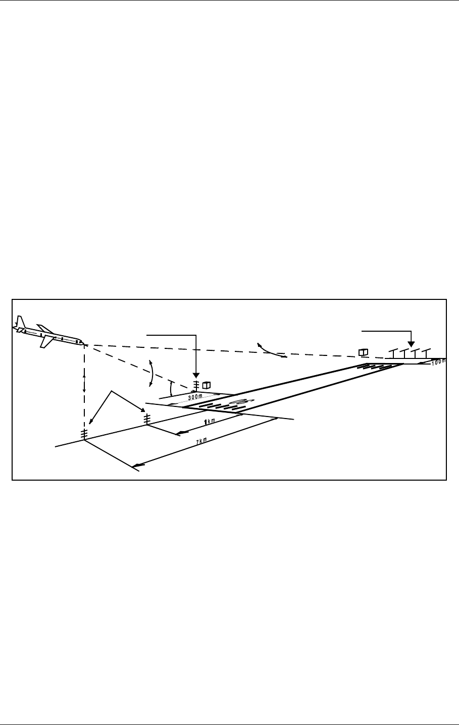
The layout of a typical ILS airport installation is shown below.
Figure 1-1Typical ILS airport installation
1.1.2 Marker Beacons Overview
The complete ILS marker beacons system comprises:
• A Marker Beacon transmitter/monitor cabinet
• A Marker Beacon antenna
• A remote control
• An Remote Maintenance Monitor (RMM) program to be installed on a PC
• Optional slave panel
• Optional backup battery
Localizer
110 MHz
Glide Path
330 MHz
Marker Beacon
75MHz
3°
HBK547-1
USER MANUAL
1-2
21464-5
NORMARC 7050
MARKER BEACON
GENERAL INFORMATION ©1999 Navia Aviation AS
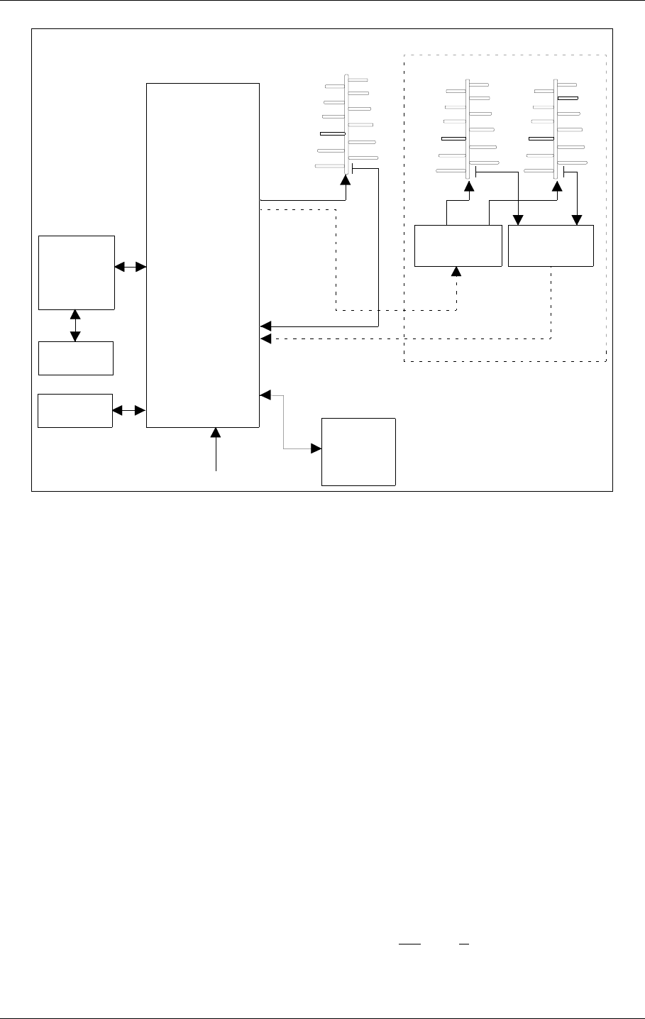
Figure 1-2 Marker beacon block diagram
1.1.3 Marker Beacons Description
The marker beacons are located vertically beneath the localizer course line at distance 150m
(inner marker), 1km (middle marker) and 7km (outer marker) from the runway threshold.
The beacons radiate a 75MHz radio signal with an audio Morse code. The Morse code and
modulation frequency differ for the outer, middle and inner marker. Outer marker transmits
dash code 400Hz, middle marker transmits dash dot code 1300Hz and inner marker dot code
3000Hz.
1.2 Product Type Numbers
The Normarc product numbering system is based on the following three levels:
•System
• Assembly
• Module
Systems have type numbers starting with NM, for example NM7050. Systems consist of
assemblies, modules and parts.
Assemblies have type numbers consisting of three letters, a three- or four- digit number and a
letter, for example CAA 1370A. CAA is an abbreviation of CAbinet Assembly, 1370 is a run-
ning number, and the last letter is the variant designator. Assemblies can consist of assem-
blies, modules and parts.
REMOTE
CONTROL
UNIT
SLAVE
PANEL
RMM
SYSTEM
TRANSMITTERS
AND
MODULATORS
24V
BATTERY
MONITOR(S)
POWER
SUPPLY(S)
MAINS INPUT
220V/110V AC
BEACON
ANTENNA
MARKER
BEACON
CABINET
DISTRIBUTION
NETWORK
MONITOR
NETWORK
RF OUT
RF IN
DUAL ANTENNA SYSTEM
HBK779/1

©1999 Navia Aviation AS 21464-5 GENERAL INFORMATION
USER MANUALNORMARC 7050
MARKER BEACON
1-3
Modules have type numbers consisting of two letters, a three- or four- digit number and a let-
ter, for example MO 1374A. MO is an abbreviation of MOnitor, 1374 is a running number, and
the last letter is the variant designator. Modules consist of parts.
1.3 Abbreviations
AC :Alternating Current
ADC :Analog to Digital Converter
AGC :Automatic Gain Control
CPU :Central Processing Unit
DAC :Digital to Analog Converter
DC :Direct Current
DM :Depth of Modulation
EEPROM :Electrically Erasable Programmable Read Only Memory
EMC :Electro Magnetic Compatibility
EMI :Electro Magnetic Interference
EPROM :Erasable Programmable Read Only Memory
FIFO :First In First Out
FPGA :Field Programmable Gate Array
I/F :Inter Face
ILS :Instrument Landing System
IM :Inner Marker
LED :Light Emitting Diode
LF :Low Frequency
LRU :Line Replaceable Unit
MCU :Monitor Combiner Unit
MM :Middle Marker
NAV :NAVigation signals
NF :Near Field
OM :Outer Marker
PC :Personal Computer
RAM :Random Access Memory
RF :Radio Frequency
RMM :Remote Maintenance Monitor
RMS :Remote Monitoring System
ROM :Read Only Memory
RTC :Real Time Clock
SC :Station Control
SRAM :Static Random Access Memory
STB :STandBy
SW :Soft Ware
TX :Transmitter

©1999 Navia Aviation AS 21464-5 Physical organisation
USER MANUALNORMARC 7050
MARKER BEACON
2-1
2 Physical organisation
This chapter describes the physical outline of the NM 7050
2.1 Configurations
2.1.1 Module and Assembly Location
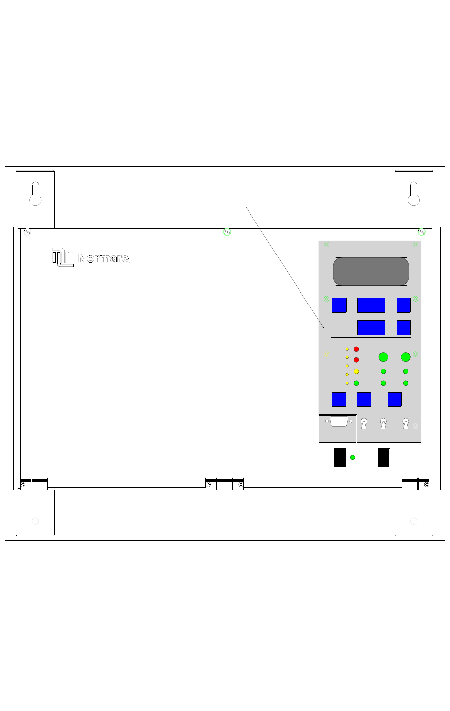
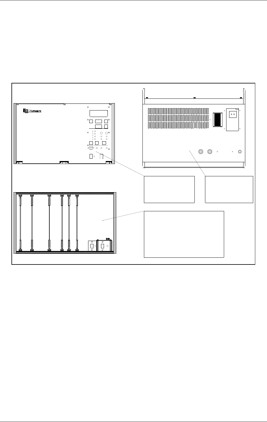
The figures on the following pages show the locations of the modules in the main cabinet.
Figure 2-1 shows the front panel of the cabinet, with the control panel, on/off switch and local
PC connection.
Figure 2-1 NM 7050 Front panel
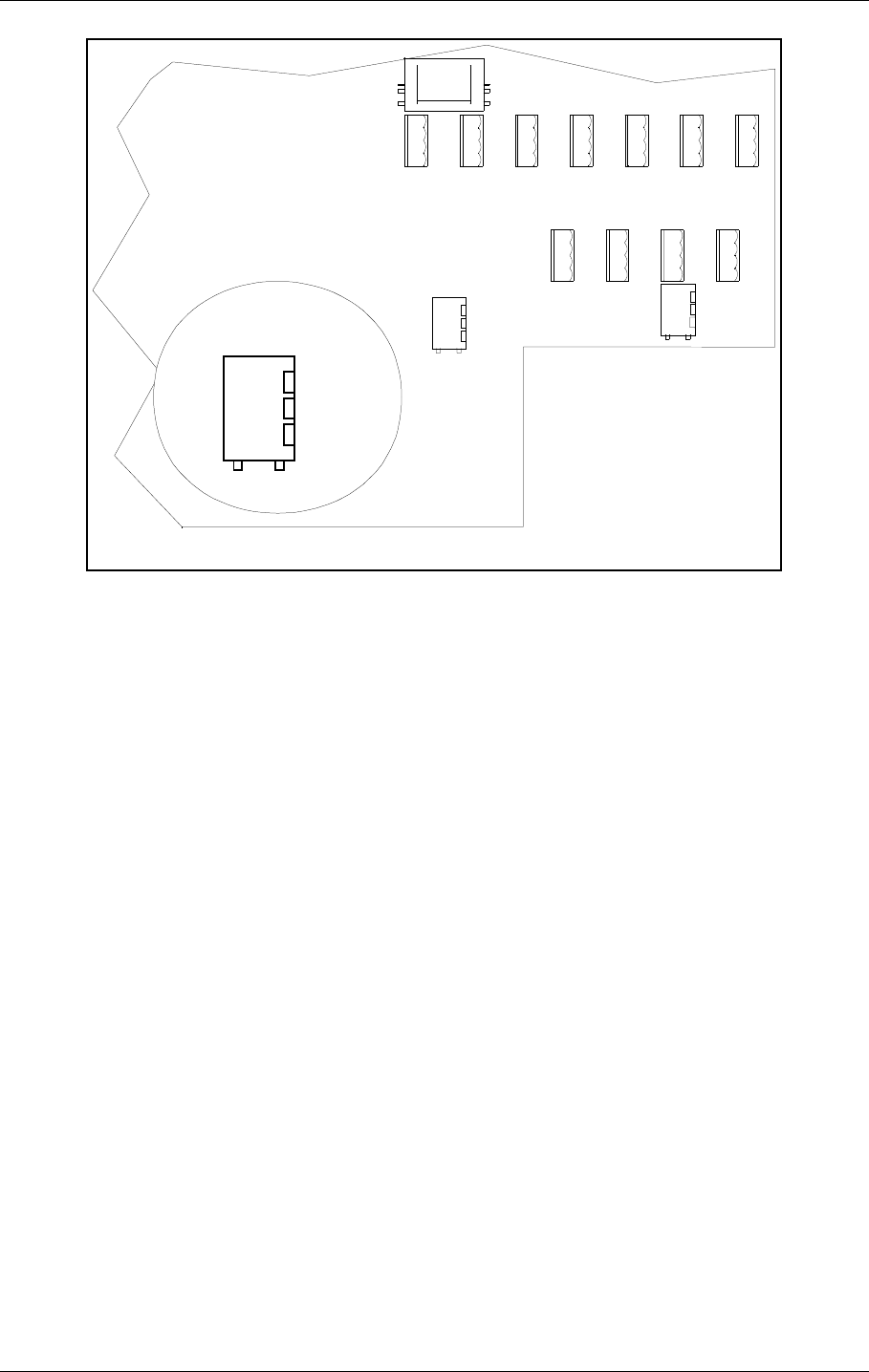
Figure 2-2 shows the open cabinet in front view with indication of plug in board location.
24V DC MAINS
MARKER BEACON SYSTEM
MAIN
OFF
ON
TX TO AIR
LOCAL RS232
POWER
ON
OFF
LOCAL
REMOT E
MANUAL
AUTO
STBY
DISAGR
PARAM
MAINT
BATT
NORMAL
ON/
OFF
CHANGE
OVER
SERVICE
WARNI NG
ALARM
TX1
ESC PREV NEXT
PROTECT
WRIT E
TX1/
TX2
TX2
ENTER
LC1377
HBK780/1
USER MANUAL
2-2
21464-5
NORMARC 7050
MARKER BEACON
Physical organisation ©1999 Navia Aviation AS
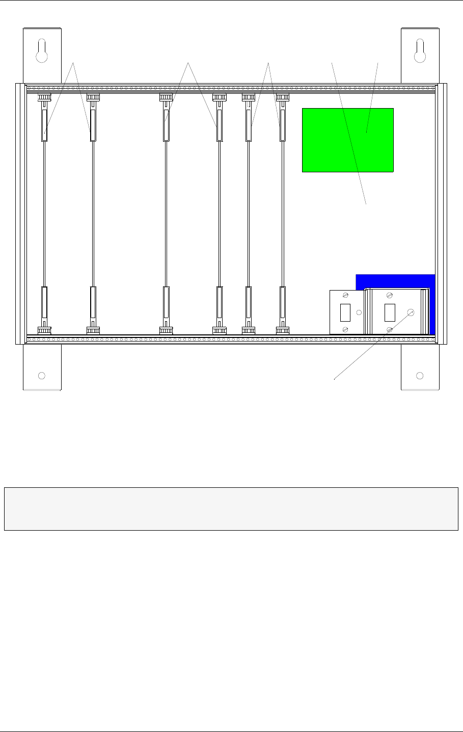
Figure 2-2 NM 7050 Module Location
Notice the location of the different plug in boards. It is essential for the MB to function, that the
cards are placed in these locations. If your MB is configured with only one plugin board of
each type, they must be placed in the number one locations. The backplane is however ,
marked with notifications of where each boards place is..
ΤThe electronic devices inside NM 7050 are sensitive to Electro Static Discharge
(ESD). Please follow the instructions given in the preface of this manual to avoid
damage during servicing and transportation.
PS 1375 TX 1373 MO 1374 PB 1378CI 1376
A
N
T
I
S
T
A
T
Antistatic socket
POWER SUPPLY 1
POWER SUPPLY 2 *)
TRANSMITTER 1
TRANSMITTER 2
MONITOR 1
MONITOR 2 **)
*) Only used in dual power systems (NM 7050 B/D)
**) Only used in dual monitor systems (NM 7050 C/D)
HBK781/1

©1999 Navia Aviation AS 21464-5 System Description
USER MANUALNORMARC 7050
MARKER BEACON
3-1
3 System Description
3.1 Introduction / Overview
The system is housed in a compact cabinet. There are four models/configurations of the NM
7050.
Table3-1 Models / Configurations
As shown in Table 3-1, the beacon can have one or two monitor units and one or two power
supply units. Figure 3-1 shows a block diagram of the MB system.
The monitor and transmitter control function is based on software. The system is based on
modern technology with extensive Remote Monitoring and Maintenance capabilities, and very
high reliability and integrity.
Variant Monitor Power Supply
NM7050A 1 1
NM7050B 1 2
NM7050C 2 1
NM7050D 2 2
USER MANUAL
3-2
21464-5
NORMARC 7050
MARKER BEACON
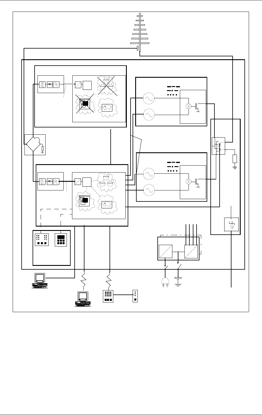
System Description ©1999 Navia Aviation AS
Figure 3-1 MB block diagram
3.2 Transmitters / Modulators
The NM7050 consists of two TX1373A transmitters. The main transmitter is connected to the
antenna, while the standby transmitter is connected to dummy load. A failure in the main
transmitter will cause an automatic change over to the standby transmitter.
The audio signals are generated in the LF circuitry mainly by a Field Programmable Gate
Array (FPGA). A strap field selects Inner, Middle or Outer Marker settings.
An onboard oscillator generates a 75MHz carrier wave which is amplitude modulated with the
LF
GENERATOR
RF
OSCILLATOR
POWER
AMPLIFIER
CHANGE
OVER
LOCAL
CONTROL
TX1/TX2
ON/
OFF
75 MHz
400 Hz
1.300 Hz
3.000 Hz
KEYBOARD
DISPLAY
AD
CPU
NM7050 - MARKER BEACON
STATION
CONTROL
ADCPU
MONITORING
MAINTENANCE +
RMM INTERFACE
MONITOR RF
FRONTEND MONITOR
BASEBAND+
RF LEVEL
OPTIONAL MONITOR 2
REMOTE
CONTROL
SLAVE
PANEL
LOCAL PC
REMOTE PC
RMM
POWER
SUPPLY
CONNECTION
INTERFACE
TRANSMITTER 1
TRANSMITTER 2
MONITOR RF
FRONTEND MONITOR
AC
DC
DC
DC
LINE+
MODEM
MONITOR 1
OPTIONAL POWER
MO 1374
MO 1374
TX 1373
LC 1377
CI 1376
PS 1375
DUMMY
LOAD
MAINS BATTERY SENSORS ETC.
BASEBAND+
RF LEVEL
MAINTENANCE +
RMM INTERFACE MONITORING
STATION
CONTROL
SPLITTER ONLY PRESENT
IF TWO MONITORS
LF
GENERATOR
RF
OSCILLATOR
POWER
AMPLIFIER
75 MHz
400 Hz
1.300 Hz
3.000 Hz
TX 1373
ON/
OFF
MODULATION DEPTH
OUTPUT RF LEVEL
KEYING NORMAL/OFF/CONT.
STATUS
+20V
+/-15V
+5V
MONITOR 2
DATA
LINE+
MODEM
HBK782/1
RMM

©1999 Navia Aviation AS 21464-5 System Description
USER MANUALNORMARC 7050
MARKER BEACON
3-3
audio signal in the Power Amplifier (PA). The PA is capable of delivering up to 4W power at
97% depth of modulation.
Unwanted frequencies are removed by a lowpass filter after the PA.
3.3 Monitors / Transmitter Control
The marker beacon has one or two MO1374 monitor modules depending on model (Table 3-
1).
The MO1374 is mainly a microprocessor based module. It contains the MB software and
forms the basis of the monitor, station control, system maintenance handling and RMS user
interface.
A detection of error in the transmitter signal causes change-over to the standby transmitter.
Failure of the standby transmitter leads to an alarm and optional shutdown of the standby
transmitter.
On a system with two monitor units, both must report error for alarm to be generated (2 of 2
voting). If the monitors disagree, the WARNING and DISAGR LEDs on the front panel is lit.
The MO1374 consists of two submodules:
The RF frontend receives a RF signal from the antenna (or recombining network for dual
antenna system). It demodulates the signal into analogue values propotional to the RF
power, the modulation depth and the morse code envelope. These parameters are digitized
and monitored by the CPU section.
The CPU section includes an 80CI88 CPU, memory, communication ports and an AD con-
verter system.
3.4 Power Systems
The marker beacon can have either one or two PS1375 power modules depending on model
(Table 3-1). The PS1375 is 100W with 120V or 230V AC input voltage and +28V/3.5 A, +20/
2.5A, ±12V/1.25A and 5V/6A DC output voltages. Outputs are short circuit protected. On the
NM7050 B/D the two modules operate in parallel.
The 28V output is temperature compensated to ensure optimum battery charging. It gives
26.4V at 50°C and linearly increase to 29.6V at -30°C.
The backup battery is an external 24V battery. The battery gives a backup time of 6 hours,
and have external charging possibilities for longer backup time. This battery is automatically
brought into circuit on mains power failure. The charging time is approximately eight hours
with one PS1375 and five hours with two PS1375.
3.5 Remote control system
The remote control unit is used in the tower or in the technical control room. It has indicators
for operating status as well as detailed warnings and an aural alarm device with reset. It can
control equipment on/off and change over, and has an Access Grant switch to allow/inhibit
remote control from the RMM system.
USER MANUAL
3-4
21464-5
NORMARC 7050
MARKER BEACON
System Description ©1999 Navia Aviation AS
The Remote Control Unit is connected to the MB by one pair telephone cable.
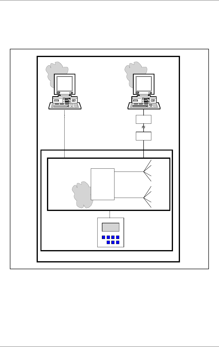
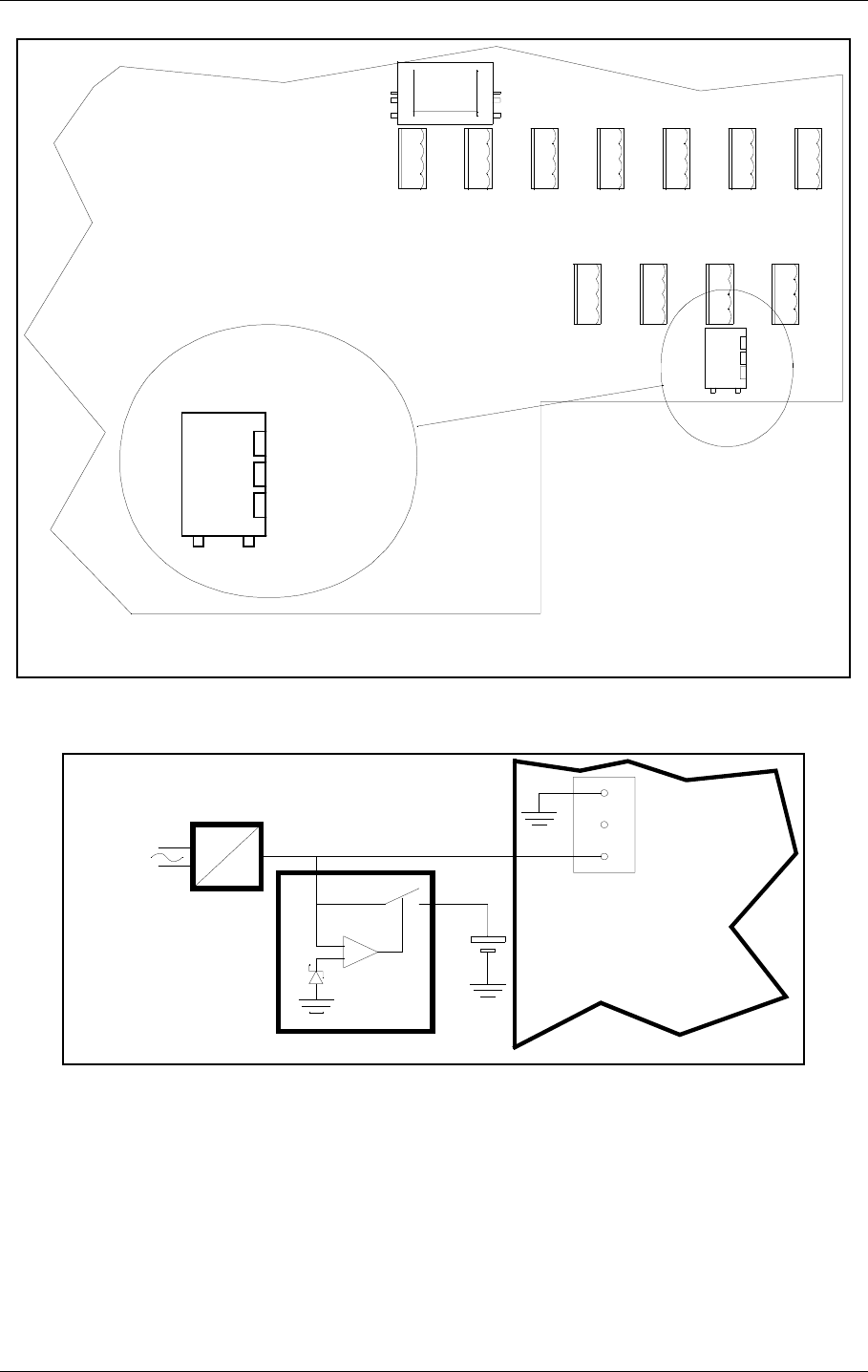
3.6 Remote Maintenance Monitoring (RMM)
The NM7000 series has a built-in Remote Maintenance Monitoring system. This system con-
sists of the RMS system, remote PC terminals with the RMM program installed, and the local
keyboard/display. Figure 3-2 illustrates the RMM/RMS systems.
Figure 3-2 The NM 7050 RMM/RMS systems
The centre of the RMM system is a CPU with the RMS core program. The RMS collects mea-
surements and diagnostic data, and makes them available to the user. The collected informa-
tion allows easy and cost effective maintenance, fault finding and routine reporting. In
addition, system settings are distributed and parameter readings are collected via the RMS/
CPU.
External Personal Computers are used for a user friendly interface to the RMM system. The
equipment has two serial output ports, typically used to connect a local PC and a connection
to a central maintenance facility.
RMS
hardware
RMS
core
program
Local
measuring
points
Maintenance
data bus
RMS
data bus
Local
parameter
storages
Local
Keyboard/
Display
Modem
NM7050
RMS system
RMM system
Local
Remote
RMM
program
Modem
program
RMM
HBK783-1

©1999 Navia Aviation AS 21464-5 System Description
USER MANUALNORMARC 7050
MARKER BEACON
3-5
The local keyboard/display allows readings and controls through an LCD display and a seven-
button keypad. This gives access to the RMM functionality without the need for a PC.
3.7 RMM Access
Access to the RMM system is controlled by multiple hardware and software access controls.
One password is required for each access level, i.e. one password for level 1, two for level 2
and three for level 3. Optional hardware controls may inhibit writing in the upper access lev-
els.
Access level 1
• Readout of all the monitor values, warning and alarm limits.
• Readout of all the maintenance values and warning limits.
• Readout of all the delays.
Access level 2
• TX1 and TX2 : morse normal, continuous or off.
• TX1 and TX2 : test signals 50% depth of mod. and 50% RF level.
• Diagnostics.
Access level 3
• Settings of all the monitor warning and alarm limits.
• Settings of all the maintenance warning limits.
• Settings of all the delays.
3.8 Storage Functions
The RMS has the following storage functions:
Alarm Storage:
8 alarm logs can be stored. One log consists of a CURRENT LOG and a HALF MIN LOG.
Current log is a continuous 2 seconds log of monitoring and maintenance parameters. Half
min log is a 30 seconds log of monitoring and maintenance parameters sampled at 5 second
intervals. A log is stored when a SHUT-DOWN or CHANGE-OVER alarm occurs.
Periodic Storage:
Stores 16 data sets of monitored data on configurable periodic intervals.
Event Storage:
Stores the last 50 events. Each event is stored with a TIME_STAMP and a USER_ID (of the
user executing the command). Stored events are; change in WARNING and ALARM states,
excution of STATION CONTROL COMMANDS, changes in WARNING and ALARM LIMITS on
logout from access level 3, SYSTEM ADMINISTRATION, and log-in and log-out at access
level 2 and 3.
3.9 Local Keyboard/Display Functions
Through a menu based interface all main commands, adjustments and monitor limits are
accessible from the front panel keypad and LCD display. In addition a quick read function
gives readout of all main monitor parameters at a glance.
USER MANUAL
3-6
21464-5
NORMARC 7050
MARKER BEACON
System Description ©1999 Navia Aviation AS
3.10 Diagnostic functions
The system contains internal measuring points and diagnostic functions to isolate faults to
failed modules. The values measured are referred to as maintenance parameters. Refer to
Chapter 10.
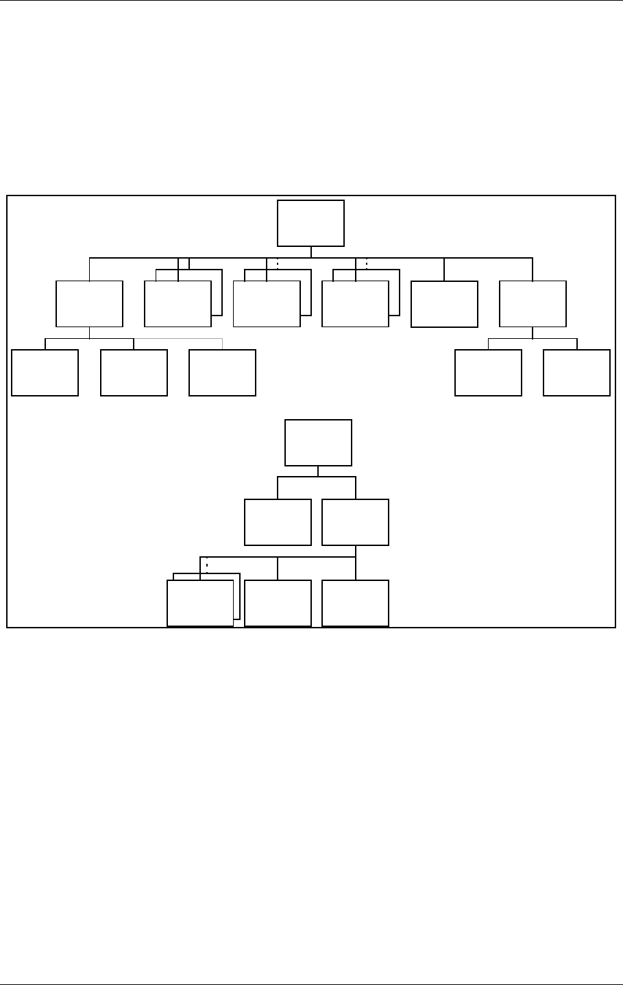
3.11 Document structure
In Figure 3-3 the document structure is shown. The upper tree is the contents of the cabinet,
while the lower tree is additional tower equipment.
Figure 3-3 Document structure NM 7050 Marker Beacon system
CAA1370A
Cabinet
Assembly
NM7050A-D
Marker
Beacon
TX1373A
Transmitter MO1374A
Monitor PS1375A
Power
Supply
CI1376A
Connection
Interface
PB1378A
Piggy
Back
RC1241A
Remote
Control
RF1242A
Remote
Front
RCA124 0A
Remote
Control
Assembly
LC1377A
Local
Control
SF1344A
Slave
Front
MB1346/7A
Motherboard
CA1348A
Cabinet
PS635B
Power
Supply
RFA1353
Remote
Frame
Assembly
CH1385A/B
Cable
Harness
Additional
Tower
Equipment
HBK859/1

©1999 Navia Aviation AS 21464-5
USER MANUALNORMARC 7050
MARKER BEACON
4-1
Technical Specifications
4 Technical Specifications
NM 7050 Marker Beacon Cabinet.
4.1 Signal Requirements
4.1.1 Transmitter
4.1.2 Modulator
Frequency range 75 MHZ
Frequency tolerance ±0,005 %
Output power range 0,005 – 4 W adjustable.
Fixed attenuator optional in lower range
Harmonic radiation 2,5 UW maximum
spurious radiation 25 UW maximum
OUTPUT POWER STABILITY ±0.5DB
Test function Preset adjustable RF level
MODULATION TYPE AM
Modulation alternatives
KEYED
CONTINUOUS
OFF
MODULATION FREQUENCY AND IDENTIFICATION
INNER MARKER 3000 HZ•Τ•Τ•Τ•Τ•Τ•Τ•
MIDDLE MARKER 1300 HZΤΤ•ΤΤΤΤ•
Outer marker 400 HZΤΤΤΤΤΤ
Modulation depth 95%
adjustable range 45-97 %
MAX. STEP SIZE 0,5 % Depth of Modulation
stability ±4 % Depth of Modulation
Frequency tolerance ±2,5 %
Total harmonic dist. 8 %maximum
Keying
Speed 125 MS/DOT APPROX.
PAUSE TO DOT RATIO 1:1
PAUSE TO DASH RATIO 1:3 dots/SEC
2 dashes/sec
Test function Preset adjustable Depth of Modulation,
normal, continous or no keying

USER MANUAL
4-2
21464-5
NORMARC 7050
MARKER BEACON
Technical Specifications ©1999 Navia Aviation AS
4.1.3 Monitoring
4.1.3.1 Alarm Functions
4.1.3.2 Monitor input levels
4.1.3.3 Monitor stability at nominal levels
4.1.3.4 Warning funktion
4.1.3.5 Protocols
4.1.4 Remote Control
RF power reduction 1,5-3 DB adjustable
Change of modulation depth 50-70 % Depth of Modulation
Keying absence
Alarm identification to automatic
transmitter change over
SENDERUMSCHALTUNG 2-5 sec.
LINE BREAK MB - Remote Control
(DISABLE OPTIONAL) Standby alarm identification
to transmitter shutdown shall be configurable.
Adjustment range, nominal level +1 TO -25 DBM (strap settings for IM, MM
and OM sensitivity)
RF POWER VALUES ±0,5 DB
MODULATION DEPTH VALUES ±1,0 % Depth of Modulation
@ 10 – 30 ºC
±3,0 % Depth of Modulation
@ full temp. range
±2,0 % Depth of Modulation
variation for 3dB RF
reduction @ 10-30°C.
RF POWER REDUCTION 40-75 % of alarm limit
Change of modulation depth 40-75 % of alarm limit
Maintenance parameter outside limits
Mains failure
Monitor 1 to monitor 2 communication SERIAL DATA PROTOCOL (not RS 232)
RMM DATA PROTOCOL RS232
Either

©1999 Navia Aviation AS 21464-5
USER MANUALNORMARC 7050
MARKER BEACON
4-3
Technical Specifications
4.2 Environmental characteristics
4.3 EMV-charakteristics
4.4 Mechanical characteristics
Data Transmission Medium 2-wire line, 600 ohm
Data modulation SERIAL, FSK
Transmitter level -10 DBM ± 2 DB
Receiver dynamic range -10 DBM... -34 DBM OR RS232
or
RS-232 interface in both Marker Beacon and remote control
Operating temperature -40 TO +55 ºC
(main cabinet except
display)
-10 TO +55 ºC
(display, remote con-
trol and slave panel)
Storage temperature -40 TO +60 ºC
HUMIDITY 95% TO +35 °C
DECREASING LINEARLY
TO 60% AT +55 °C
VIBRATION 0.15MM OR 19.6M/S2 (2G)
VERTICAL,10Hz to
500Hz
GENERAL SPECIFICATIONS FOR EMC ETS 300 339
EN50081-1 (emmission)
EN50082-2 (immunity)
EN61000-3-2 (harmonic current emmission)
EN61000-3-3 (voltage fluctuations and flicker)
SPURIOUS AND HARMONICS CISPR 22
SAFETY EN 60950
Dimensions (hxwxd):
MB CABINET 267 X 450 X 343 MM
REMOTE CONTROL 71 X 132 X 200 MM
SLAVE PANELS 51 X 132 X 200 MM
The MB rack is wall mounted. The remote control and slave panel fit a 19" shelf.

USER MANUAL
4-4
21464-5
NORMARC 7050
MARKER BEACON
Technical Specifications ©1999 Navia Aviation AS
4.5 Power supply
OPERATING VOLTAGE:
MAIN SUPPLY 230 V +15 %/-20 %, 45-65 HZ,
OR 120 V +15 %/-20 %, 45-65 HZ
STAND-BY BATTERY 24 V DC NOMINAL,
float charged by the main Supply.
The battery is able to use an external
charger.
The equipment is able to operate
without battery.
POWER CONSUMPTION:
MB CABINET: < 50 W
REMOTE CONTROL < 5 W
BATTERY CHARGER ADAPTED TO 5 HOURS (NM 7050 B/D) or 8
hours (NM 7050 A/C) charging time to 90%
battery capacity for a battery giving 6 hours
operation.
External battery charges may be connected
for longer operation, and shorter charging
time.
©1999 Navia Aviation AS 21464-5 Mechanical Installation
USER MANUALNORMARC 7050
MARKER BEACON
5-1
PART II INSTALLATION
5 Mechanical Installation
This chapter gives a brief instruction on the mechanical installation of the Marker Beacon cab-
inet and antenna. See the Engineering and Commissioning Handbook for further details.
5.1 Marker beacon Cabinet
The NM7050 cabinet is constructed for mounting on a wall. For easy operation, the keyboard
and display section should be in eye/shoulder height (140-160cm).
The ventilation holes at the bottom of the cabinet should be kept uncovered to ensure proper
cooling.
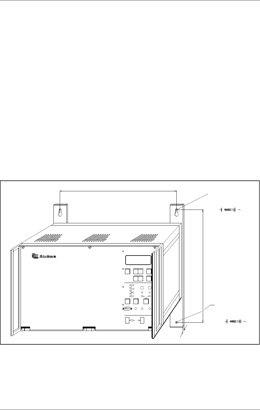
The cabinet is 45 cm wide, 34 cm deep and 27 cm height and weighs about 5 kg.
When mounting the cabinet on a wall, do the following:
• First drill the holes according to Figure 5-1.
• Mount the upper screws. Leave 6 mm distance from the screw head to the wall.
• Hang the cabinet on these screws, using the key holes on the mounting rails
• Mount the lower screws
• Tighten all screws
Figure 5-1 Mounting the cabinet on a wall.
5.2 Remote control
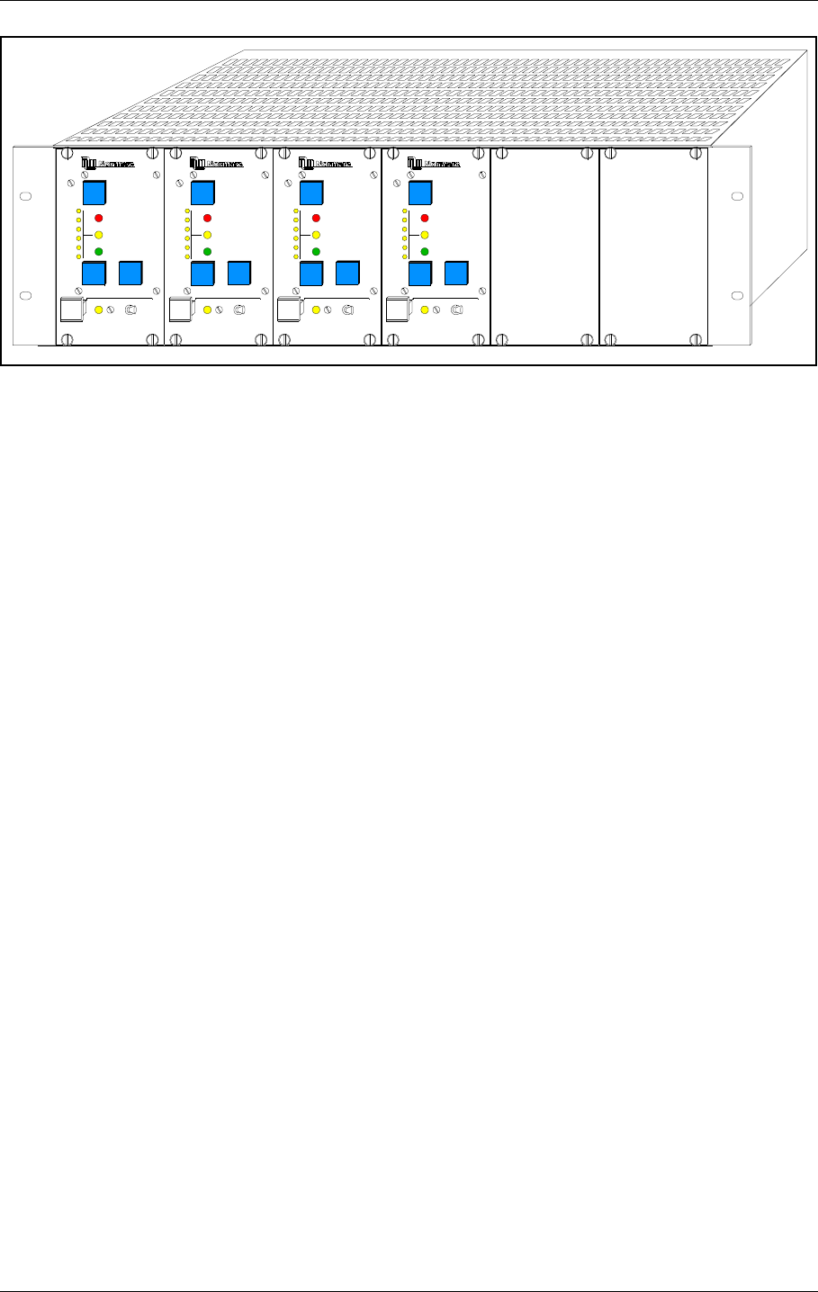
The Remote Controls are normally organised in 19" subracks three units high. Normarc offers
such a subrack called RFA 1353 (Remote Control Frame) shown in Figure 5-2. Maximum five
Remote Controls and one power supply (like PS 635) fit into RFA 1353 which is 33 cm deep.
MARKER BEACON
ON
OFFOFF
BATTERY
ON
LOCAL RS232
POWER
MAINS
REMOTE
LOCAL
AUTO
MANUAL
WRITE
PROTECT
MAIN
TX TO AIR
+
ON/
OFF
STBY
MAINT
BATT
DISAGR
PARAM
ALARM
WARNING
OVER
CHANGE
NORMAL
SERVICE TX1
ESC
-
PREV NEXT
READ
TX2
QUICK
ENTER
405
Hex lag screw 6x50
Hex lag screw 6x50
Washer M6
Washer M6
340
451 mm
5
HBK 860-1
USER MANUAL
5-2
21464-5
NORMARC 7050
MARKER BEACON
Mechanical Installation ©1999 Navia Aviation AS
Figure 5-2The Remote Control Frame RFA 1353
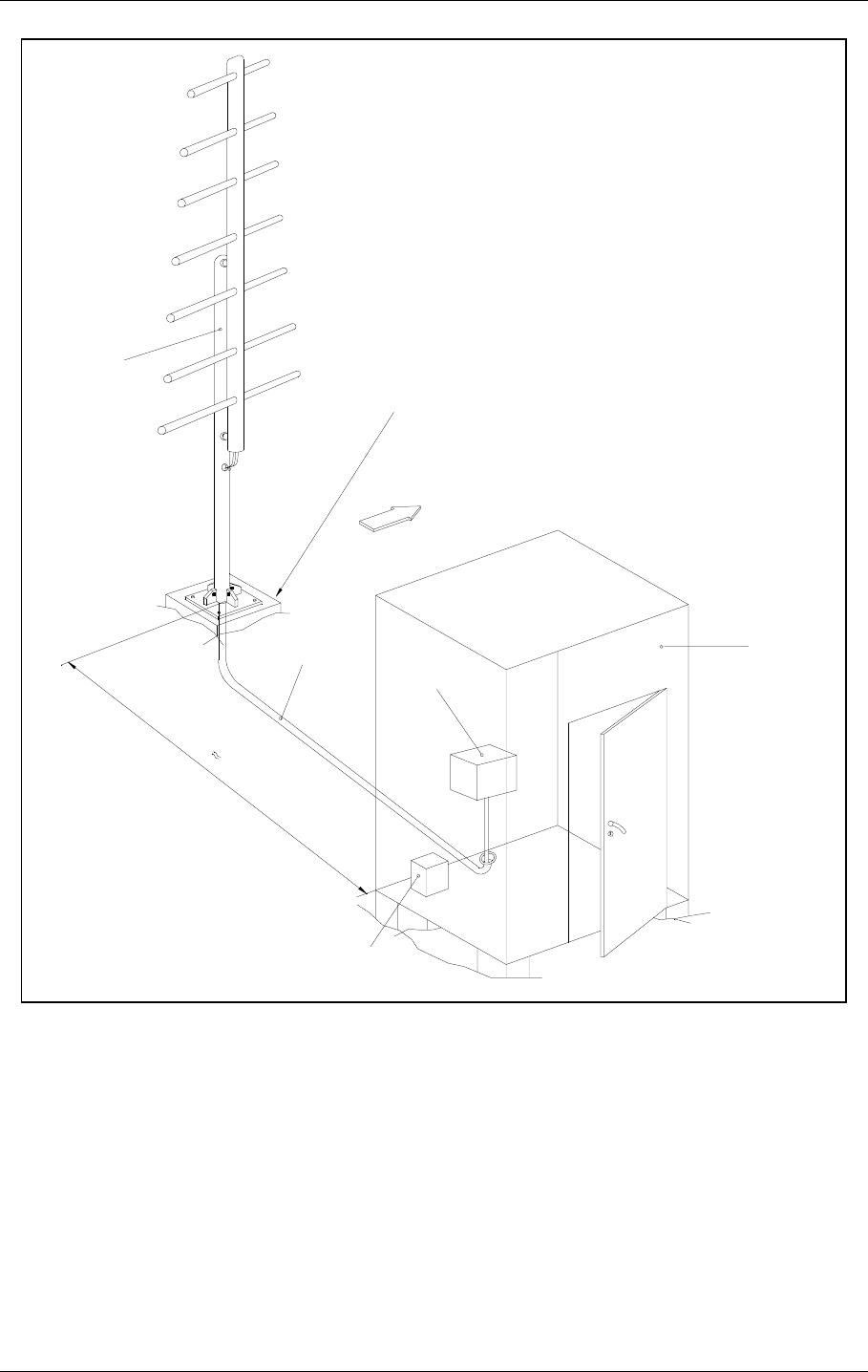
5.3 Antenna
The marker beacon antennas should be mounted on poles, with the dipoles parallel to the
course line. The rear end of the antenna should at least be 2.2 meters above the ground.
RMM
ACCESS GRANT
MAINT
STBY
OFF
ON/
NORMAL
T
IDENT
ATB
ARAM
DISAGR
P
WARNING
ALARM
DENY
SILENCE
OVER
CHANGE
RMM
ACCESS GRANT
MAI NT
STBY
OFF
ON/
NORMAL
T
IDENT
ATB
ARAM
DISAGR
P
WARNING
ALARM
DENY
SILENCE
OVER
CHANGE
RMM
ACCESS GRANT
MAINT
STBY
OFF
ON/
NORMAL
T
IDENT
ATB
ARAM
DISAGR
P
WARNING
ALARM
DENY
SILENCE
OVER
CHANGE
RMM
ACCESS GRANT
MAINT
STBY
OFF
ON/
NORMAL
T
IDENT
ATB
ARAM
DISAGR
P
WARNING
ALARM
DENY
SILENCE
OVER
CHANGE
OM
RWY01 MM
RWY01 OM
RWY19 MM
RWY19
HBK 861-1

©1999 Navia Aviation AS 21464-5 Electrical installation
USER MANUALNORMARC 7050
MARKER BEACON
6-1
6 Electrical installation
6.1 Marker beacon cabinet
6.1.1 Connection Overview
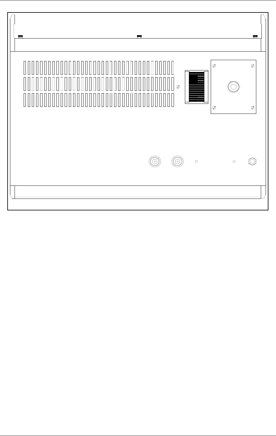
All electrical connections except the local PC connection, the mains connection and the RF IN
and OUT connections are on the CI1376 connection interface board inside the cabinet.
Figure 6-1 Marker Beacon main cabinet connection overview
6.1.2 RF In and Out
• The output signal RF OUT is connected to the antenna with N-connectors and 50 Ω coaxial
cable.
The input signal RF IN is connected to the antenna probe with N-connectors and 50 Ω coaxial
cable.
GND
L
N
RF INRF OUT
ON ON
OFF
24V DC OFF
POWER
MAINS
ON/
OFF
LOCAL RS232
DISAGR
STBY
MAINT
BATT
PARAM
REMOTE AUTO
LOCAL MANUAL
CHANGE
OVER
PROTECT
WRITE
TX1/
TX2
MAIN
TX TO AIR
NORMAL
WARNING
ALARM
SERVICE
TX1 TX2
MARKER BEACON SYSTEM
ESC PREV NEXT ENTER
CABINET UNDERSIDE
FRONT VIEW WITH FRONT PLATE
FRONT VIEW WITHOUT FRONT PLATE RF IN AND OUT
MAINS POWER
LOCAL PC (RS 232)
REMOTE CONTROL (RS 232)
REMOTE PC (RS 232)
3 ANALOGUE CHANNELS
AC LEVEL
4 DIGITAL PORTS
TEMP. INDOOR AND OUTDOOR
BATTERY
A
N
T
I
S
T
A
T
HBK784/1
USER MANUAL
6-2
21464-5
NORMARC 7050
MARKER BEACON
Electrical installation ©1999 Navia Aviation AS
.
Figure 6-2 RF cable connection
6.1.3 Battery
The external backup battery is connected between BATT GND (-) and BATT +24V (+) on the
connector marked BATTERY on CI 1376.
A 16Ah battery gives approximately six hours backup time with 5-8 hours charging time
dependent on model. For longer backup time an external charger is required to be able to
charge the battery within a reasonable time. An external battery protection circuit (like Nor-
marcs BP 543) has to be connected between the EXT. CHARGER (+) and BATT GND (-) input.
In addition MAINS directly on NM 7050 has to be disconnected. Figure 6-4 shows the connec-
tions schematically.
RF OUT RF IN
HBK785/1
©1999 Navia Aviation AS 21464-5 Electrical installation
USER MANUALNORMARC 7050
MARKER BEACON
6-3
Figure 6-3 Battery connection
Figure 6-4 External charger connection
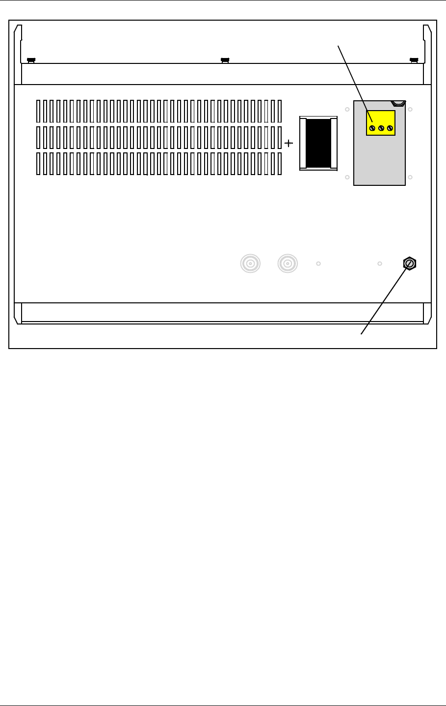
6.1.4 Mains
The mains power cable connections are underneath the cabinet. They are covered by a alu-
minium plate fastened with four screws. The cable itself is threaded through the cable gland
and the three wires are connected to the terminals N, L and GND shown below in figure 6-4.
CI 1376
REMOTE
CONTROL
LINE
TEMP
OUTDOOR
TEMP
INDOOR
AC LEVEL ANA CHA1 ANA CHA2 ANA CHA3
DIG PORT A DIG PORT B DIG PORT C DIG PORT D
BATT GND
EXT CHARGE
BATT +24V
1
2
3
BATTERY
BATT GND
EXT CHARGE
BATT +24V
BATTERY
HBK786/1
AC
DC
BP 543
BATTERY
EXT.CHARGE
BATT +24V
BATT GND
MAINS
EXTERNAL
CHARGER
BATTERY
PROTECTION
NM 7050
HBK863/1
USER MANUAL
6-4
21464-5
NORMARC 7050
MARKER BEACON
Electrical installation ©1999 Navia Aviation AS
Figure 6-5 Power connection
6.1.5 Modem Power
A DC powered modem or other external equipment designed for 22V-27V DC can be con-
nected to the terminal block marked MODEM POWER. Maximum current consumption
should be 800 mA.
MAINS POWER
GND
L
N
GROUND CABLE CONNECTION
HBK787/1
©1999 Navia Aviation AS 21464-5 Electrical installation
USER MANUALNORMARC 7050
MARKER BEACON
6-5
Figure 6-6 Modem Power
6.1.6 Remote Control
The remote line and remote control is connected to the CI 1376 connection interface board as
illustrated in Figure 6-7.
• FSK_[A,B] is the modem line pair.
• GND is main cabinet ground
A suitable female connector for the remote line is Weidemüller BLZ-5.08/4 or equivalent.
Alternatively the remote control connection is done with a RS 232 interface. The mode is con-
figured on MO 1374, refer to 7.2.3.
Note: The position of RXD and TXD is interchanged from the normal RS-232 layout in the
Remote Control connector. Therefore a special cable must be used for connection to external
equipment.
CI 1376
REMOTE
CONTROL
LINE
TEMP
OUTDOOR
TEMP
INDOOR
AC LEVEL ANA CHA1 ANA CHA2 ANA CHA3
DIG PORT A DIG PORT B DIG PORT C DIG PORT D
-(GND)
1
2
3
BATT GND
EXT CHARGE
BATT +24V
BATTERY
-
+
+ (+24V DC)
MODEM POWER
MODEM POWER
H1116/1
USER MANUAL
6-6
21464-5
NORMARC 7050
MARKER BEACON
Electrical installation ©1999 Navia Aviation AS
Figure 6-7 Remote control connection
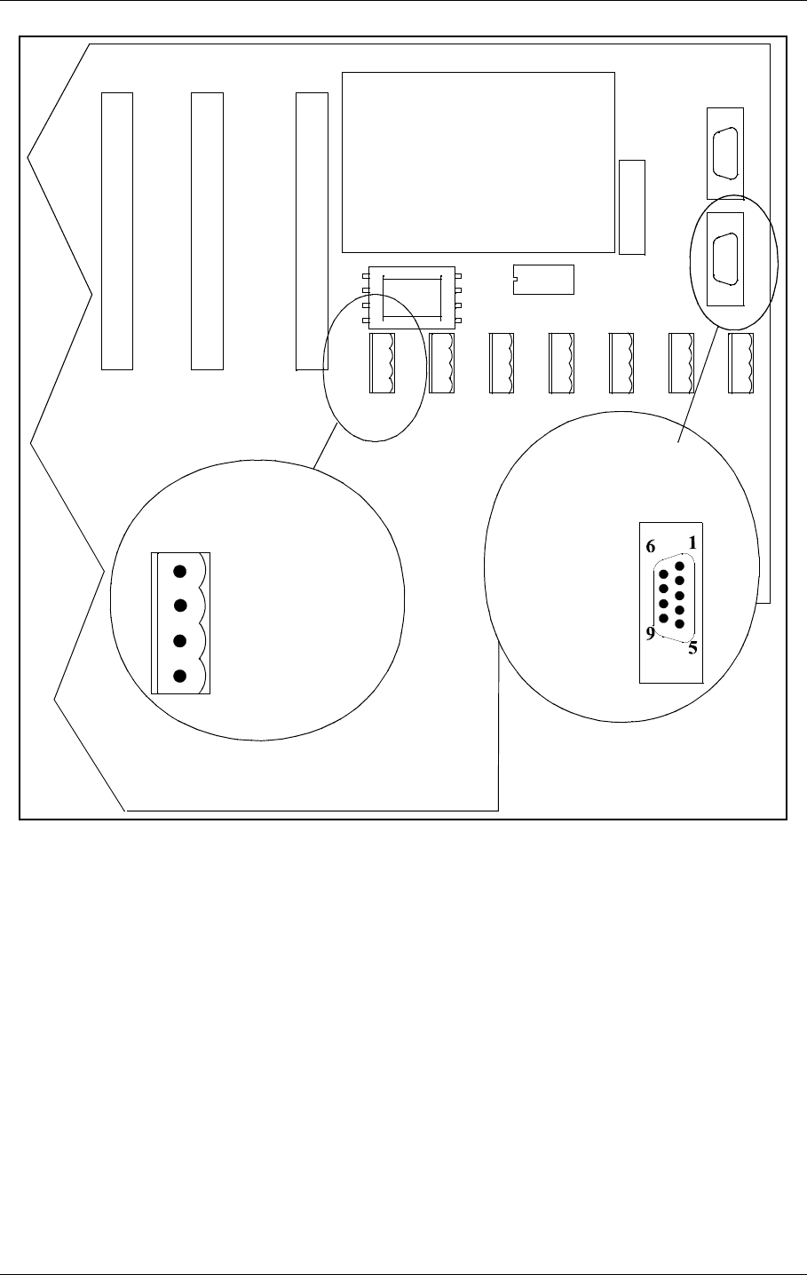
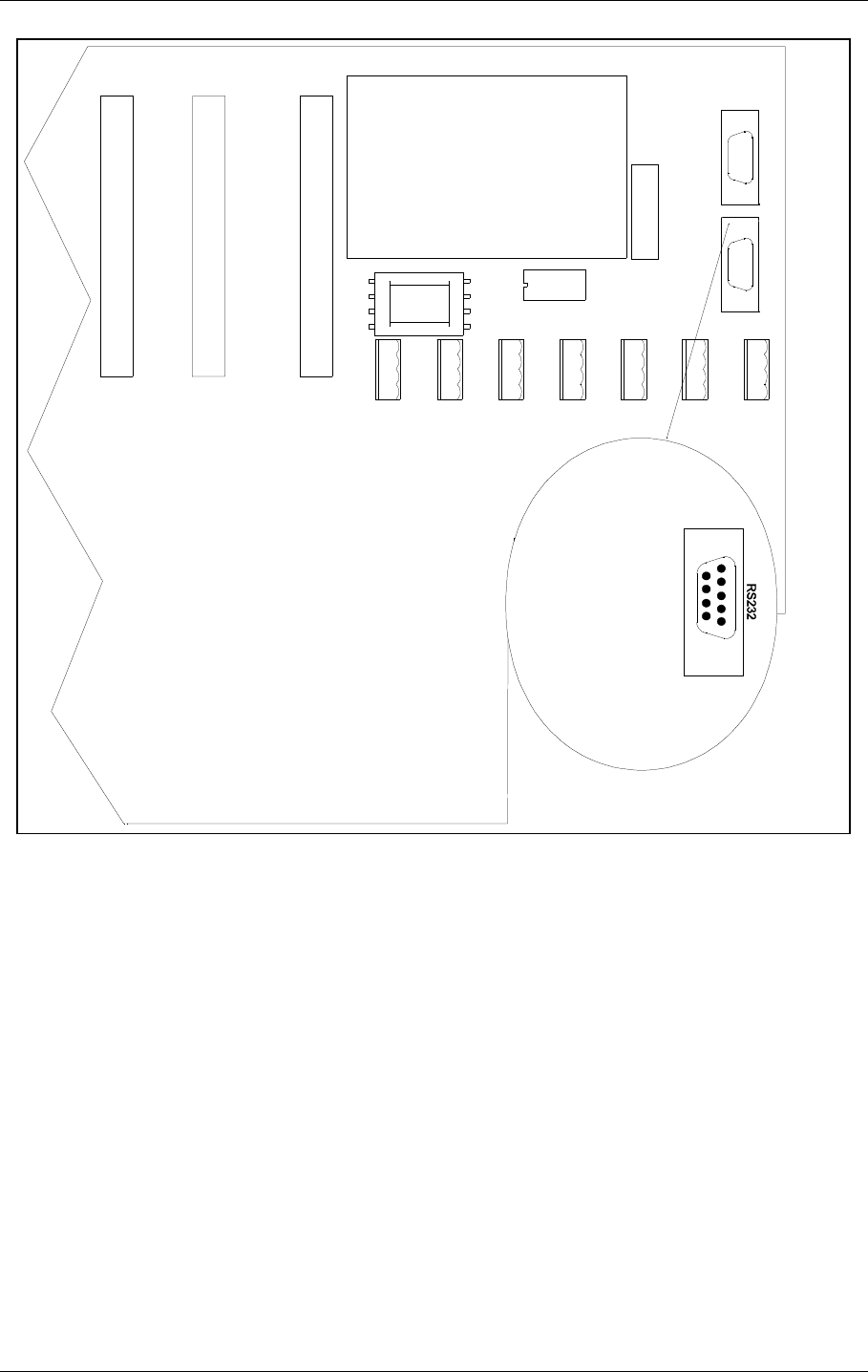
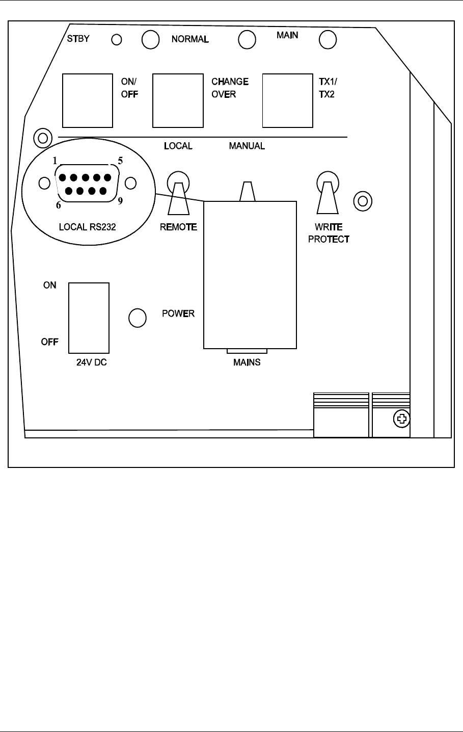
6.1.7 PC and Modem
Modem connections for remote PC are the standard pin out RS232, 9 pins DSUB connector
on the CI1376 connection interface board marked remote-rmm as illustrated in Figure 6-8.
For local PC connection use the RS232 on front panel Figure 6-9.
CI 1376
PB 1378
REMOTE
CONTROL
LINE
TEMP
OUTDOOR
TEMP
INDOOR
AC LEVEL ANA CHA1 ANA CHA2 ANA CHA3
REMOTE RMM
RS232
REMOTE CONTOL
RS232
CONFIGURATION
1 - GND
2 - RC_LINE B
4 - Not used
1 - Not used
3 - RXD
2 - TXD
4 - Not used
5 - GND
6 - Not used
7 - Not used
8 - Not used
9 - Not used
REMOTE
CONTROL
REMOTE
CONTROL
LINE
RS-232
HBK788/3
2 - RC_LINE A
©1999 Navia Aviation AS 21464-5 Electrical installation
USER MANUALNORMARC 7050
MARKER BEACON
6-7
.
Figure 6-8 Modem and modem battery backup connection
CI 1376
PB1378
REMOTE
CONTROL
LINE
TEMP
OUTDOOR
TEMP
INDOOR
AC LEVEL ANA CHA1 ANA CHA2 ANA CHA3
REMOTE RMM
RS232
REMOTE CONTOL
RS232
CONFIGURATION
DIG PORT A DIG PORT B DIG PORT C DIG PORT D
1-CD
2-RXD
3-TXD
4-DTR
5-GND
6-Not used
7-RTS
9-CTS
9-Not used
REMOTE RMM
61
95
HBK789/1
USER MANUAL
6-8
21464-5
NORMARC 7050
MARKER BEACON
Electrical installation ©1999 Navia Aviation AS
Figure 6-9 Local PC RS232 connection
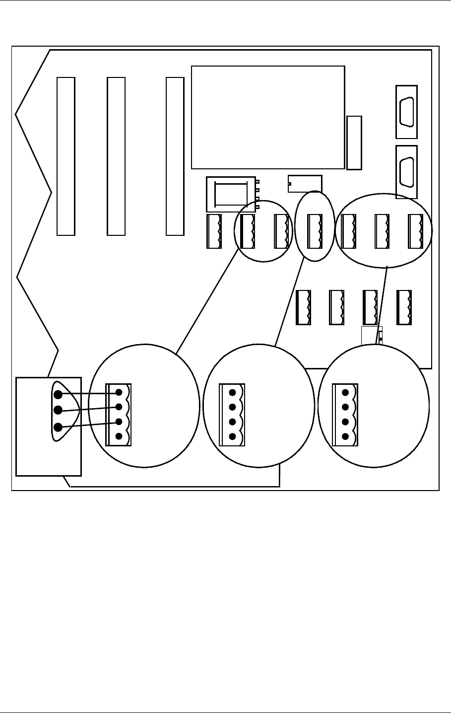
6.1.8 Analogue Inputs
The analogue inputs are connected to the CI1376 connection interface board as illustrated in
Figure 6-10.
The inputs are:
• Analogue Channel 1-3 - three differential DC analogue inputs, P (pin-1) is the positive and
N (pin-3) is the negative terminal, and pin 2 is GND.
Maximum voltage: ±15V
Input impedance: 10kΩ
• Temp Indoor and Outdoor - temperature measurement inputs with interface to an LM35
temperature sensor.
Maximum voltage: ±15V
Input impedance: 10kΩ
• AC Level - AC level measurement input. Intended for use with a battery eliminator to moni-
tor the mains voltage.
Maximum voltage: 24Vpp
1 - Not used
2 - RXD
3 - TXD
4 - Not used
5 - GND
6 - Not used
7 - RTS
8 - CTS
9 - Not used
HBK790-1
©1999 Navia Aviation AS 21464-5 Electrical installation
USER MANUALNORMARC 7050
MARKER BEACON
6-9
Input impedance: 10 kΩ
Figure 6-10 Analogue input connections
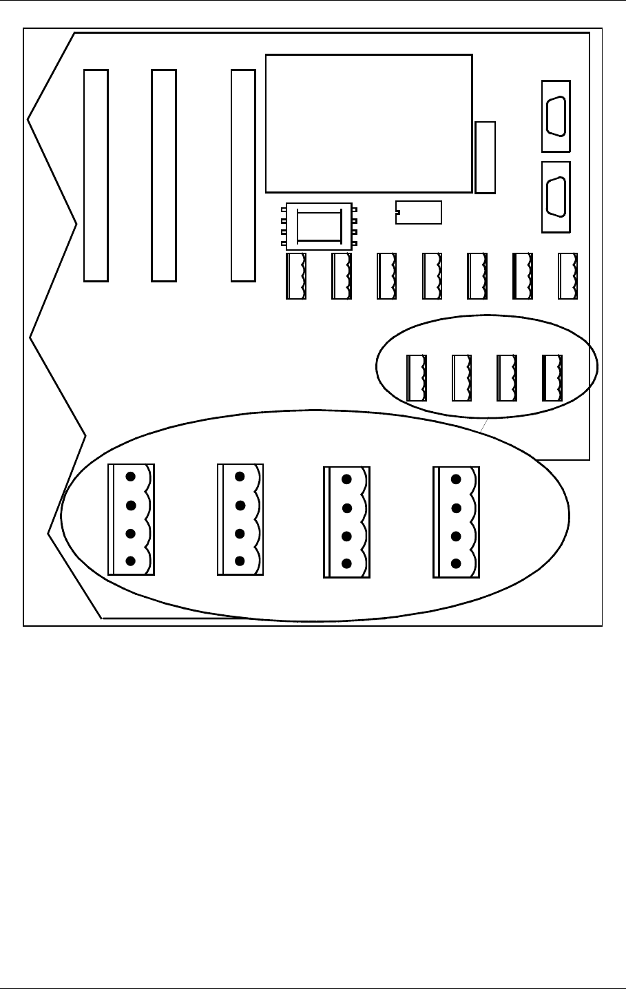
6.1.9 Digital Inputs and Outputs
Eight bi-directional digital channels (numbered 0-7) are sited on the CI1376 connection inter-
face board as illustrated in Figure 6-11.
Logical levels: TTL
Input impedance: 560Ω.
A suitable female connector is Weidemüller BLZ-5.08/4 or equivalent.
CI 1376
PB 1378
REMOTE
CONTROL
LINE
TEMP
OUTDOOR
TEMP
INDOOR
AC LEVEL ANA CHA1 ANA CHA2 ANA CHA3
REMOTE RMM
RS232
REMOTE CONTOL
RS232
CONFIGURATION
DIG PORT A DIG PORT B DIG PORT C DIG PORT D
1-ANLG*P
2-GND
3-ANLG*N
4-Not used
ANALOGUE
CHANNEL 1-3
1-VACP
2-GND
3-VACN
4-Not used
AC LEVEL
1-VDD
2-T*DOOR
3-GND
4-Not used
TEMP *
V+
Vtemp
GND
LM 35
Bottom view
HBK791/1
USER MANUAL
6-10
21464-5
NORMARC 7050
MARKER BEACON
Electrical installation ©1999 Navia Aviation AS
Figure 6-11 Digital input/output connections
6.1.10 Power for Modem or other external devices
A DC powered modem or other external equipment designed for 22V - 27V DC can be con-
nected to the screw terminal J30. Maximum current consumption should be 0.8A.
The terminal marked OUT+ is 22V - 27V DC, OUT- is ground
6.1.11 Remote Control Interface (MB rack)
The transmission medium (telephone line (FSK modem) or RS 232) to the Remote Control
can be selected by plugs and link straps S700 and S701 on the MO1374 module:
1- DIGIN 1
2- GND
3- DIGIN 0
4-GND
1- DIGIN 3
2- GND
3- DIGIN 2
4-GND
1- DIGIN 5
2- GND
3- DIGIN 4
4-GND
1- DIGOUT 0
2- GND
3- DIGOUT 1
4-GND
DIGITAL PORTS
A
B
CD
CI 1376
PB 1378
REMOTE
CONTROL
LINE
TEMP
OUTDOOR
TEMP
INDOOR
AC LEVEL ANA CHA1 ANA CHA2 ANA CHA3
REMOTE RMM
RS232
REMOTE CONTOL
RS232
CONFIGURATION
DIG PORT A DIG PORT B DIG PORT C DIG PORT D
HBK792/1
©1999 Navia Aviation AS 21464-5 Electrical installation
USER MANUALNORMARC 7050
MARKER BEACON
6-11
6.2 Tower equipment
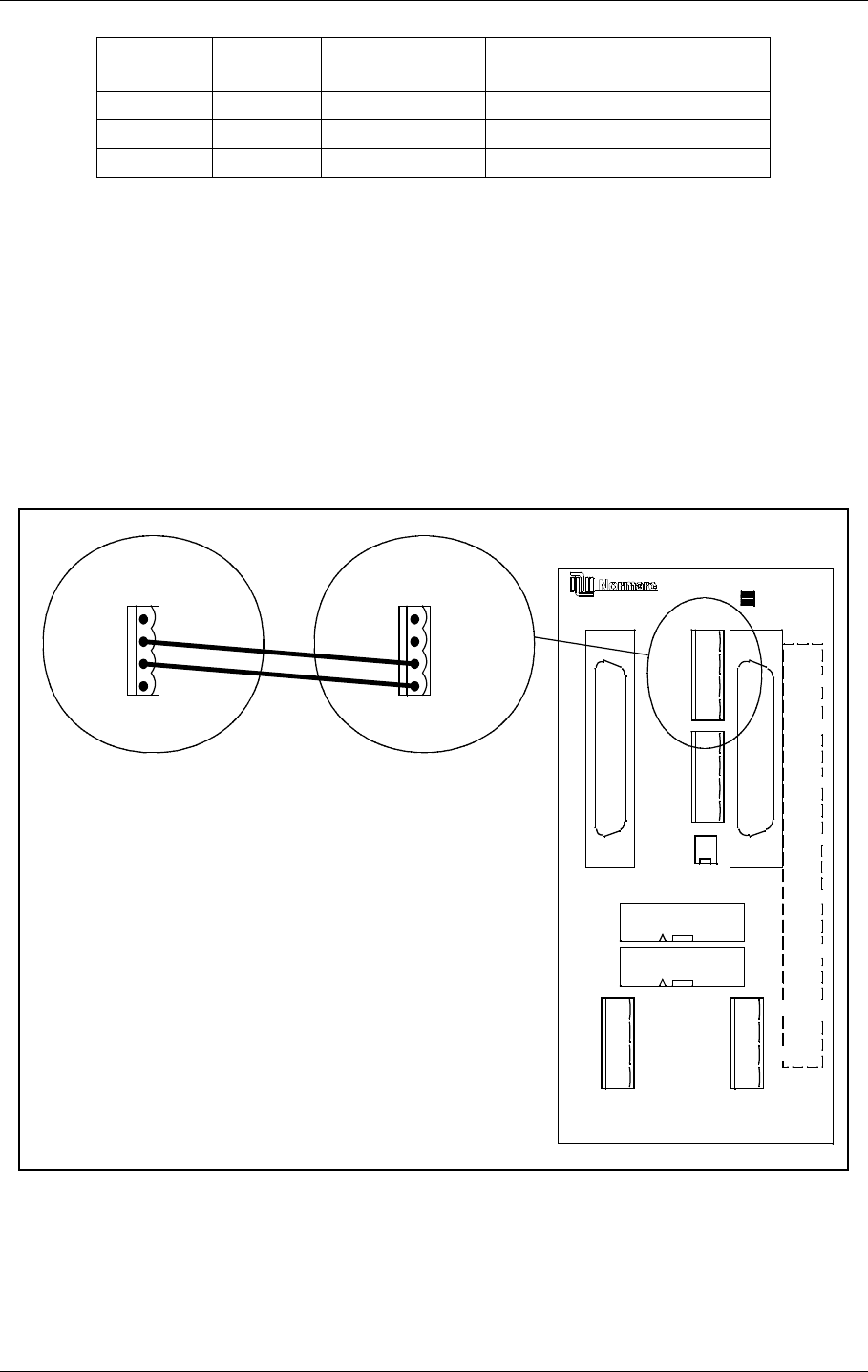
6.2.1 Remote Control Connection
The remote control is connected to the corresponding MB by connecting the REMOTE CON-
TROL connector on CI1376 to P9 on MB1346, as shown in Figure 6-12.
Suitable female connectors are Weidemüller BLZ-5.08/4 or equivalent. 600 Ω cable should
be used.
Figure 6-12 Remote control to MB connection
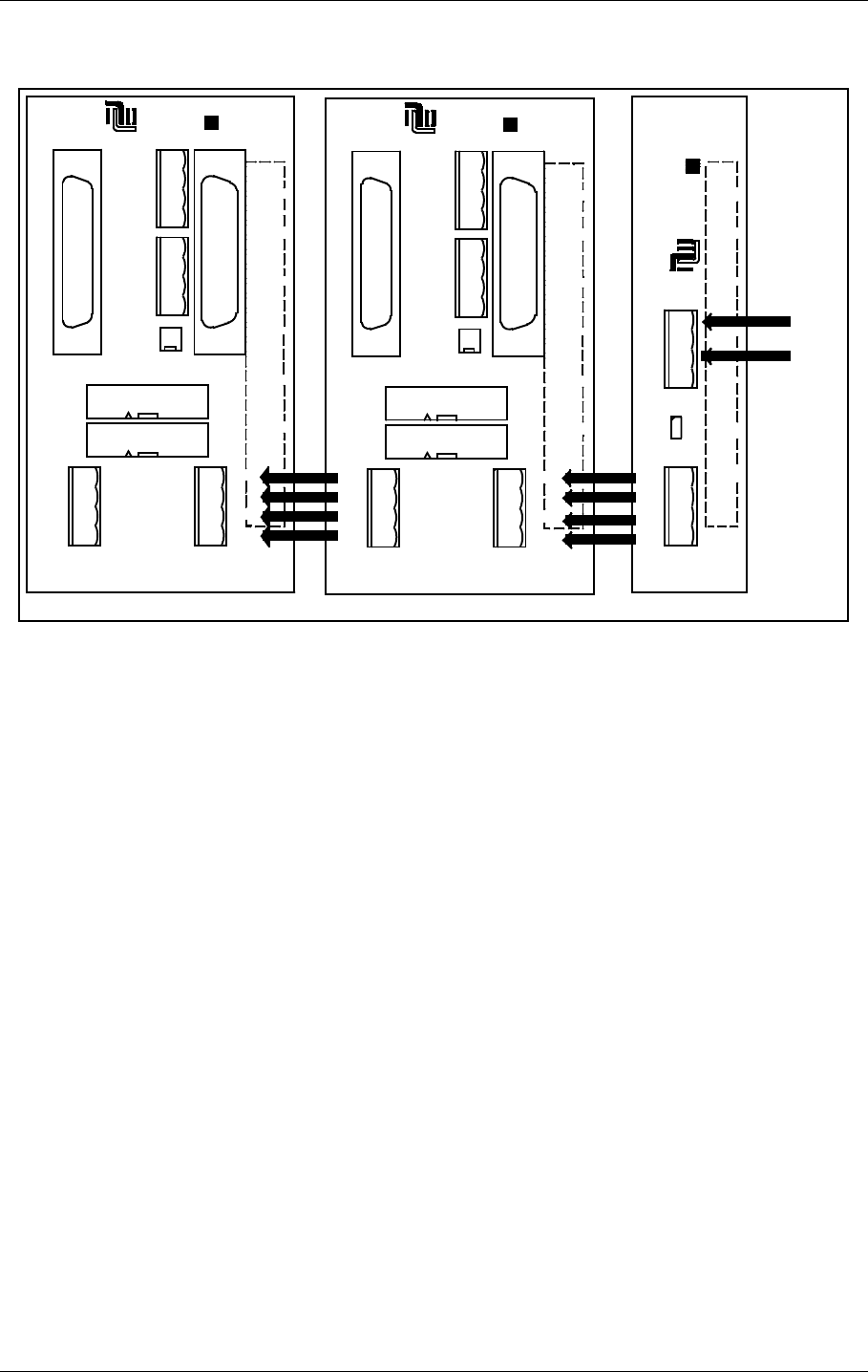
The power supply to the remote control is connected according to Figure 6-13. The battery
charger is connected to P2 on the MB1347 - power supply motherboard. Output connector P3
on MB1347 is connected to input connector P4 on MB1346 - remote control motherboard.
Several MB1346's are serial linked by connecting P5 on one board to P4 on the next.
S700 pins
connected S701 pins
connected Function Connector on CI 1376:
1-2 1-2 Telephone line P3 Remote Control Line
3-4 3-4 RS 232 P4 Remote Control RS232
5-6 5-6 Not used Not used
REMOTE
CONTROL
1 - GND
2 - FSK_P
3 - FSK_N
4 - GND
J2 P3
P6
P7
P4
P5
P9
P10
P8
OPTO OUT
2-ALARM (E)
1-ALARM (C)
4-NORM (E)
5-WARN (C)
6-WARN (E)
7-STBAL (C)
8-STBAL (E)
3-NORM (C)
GND
5V
24V
V_DIM
GND
5V
24V
V_DIM
POWER OUT POWER IN
AUX IN/OUT
SLAVE
DIRECT
INTERLOCK
TXOFF
ALARM
LINE A
LINE B
RX A
RX B
TX A
TX B
SLAVE RS485
J1
ABC
1
5
30
20
25
15
10
ALT.LINK
MB1346
P9
1 - TXOFF
2 - ALARM
3 - LINE_A
4 - LINE_B
CI1376
on
corresponding
MB
HBK793-1
USER MANUAL
6-12
21464-5
NORMARC 7050
MARKER BEACON
Electrical installation ©1999 Navia Aviation AS
Suitable female connectors are Weidemüller BLZ-5.08/4 or equivalent.
Figure 6-13 Remote control power supply connections
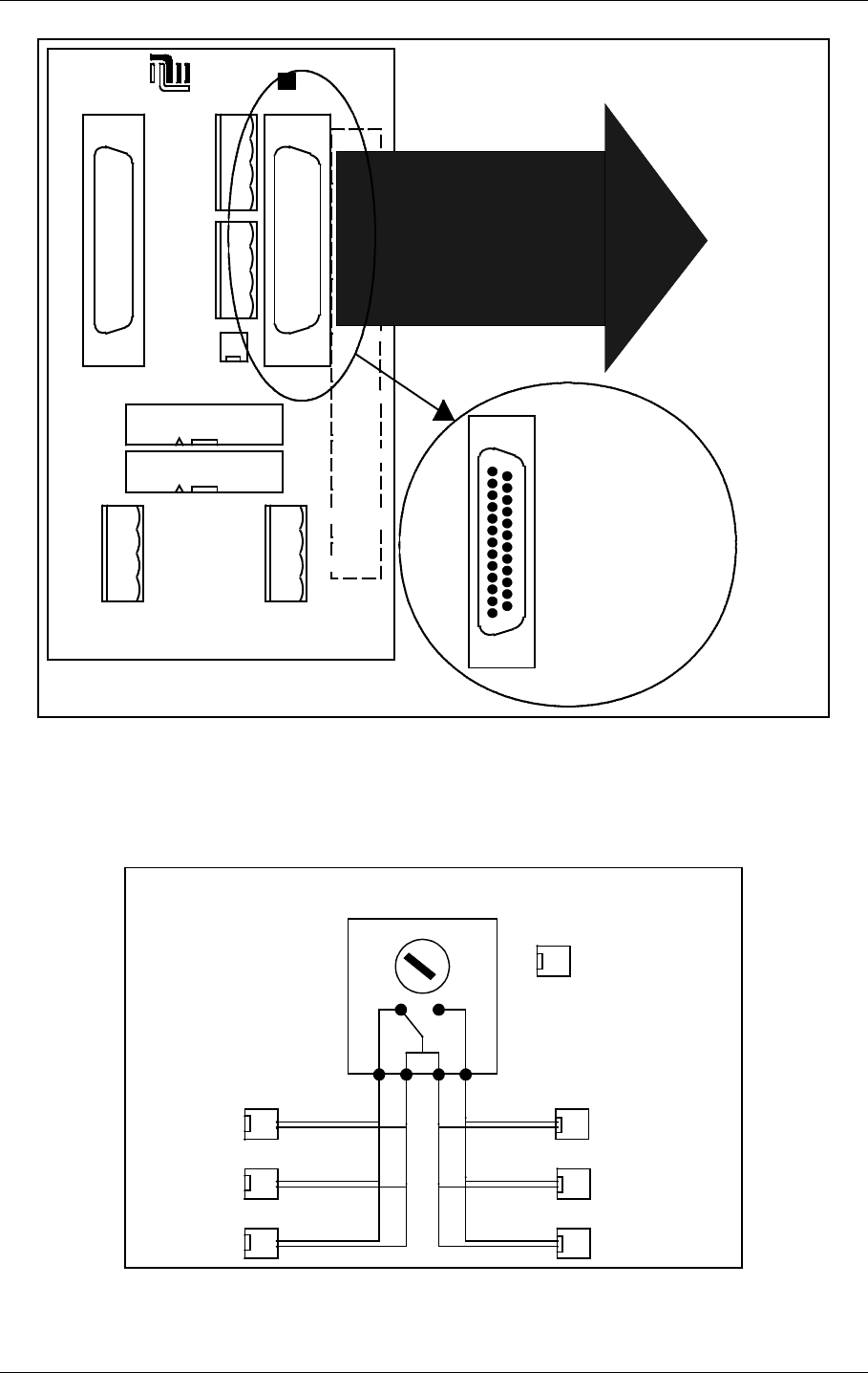
6.2.2 Remote Slave Connection
The remote slave panel SF1344 is connected to the corresponding remote control's mother-
board by connecting P3 on MB1346 to P1 on SF1344. P10 on MB1346 is not used. See Fig-
ure 6-14.
Suitable connectors are standard 25 pins female DSUB (Harting 0967 025 0442 and 0967
225 4704 or equivalent), connected by a 10 wire 1:1 cable.
J2 P3
P6
P7
P4
P5
P9
P10
P8
NORMARC
OPTO OUT
2-ALARM (E)
1-ALARM (C)
4-NORM (E)
5-WARN (C)
6-WARN (E)
7-STBAL (C)
8-STBAL (E)
3-NORM (C)
GND
5V
24V
V_DIM
GND
5V
24V
V_DIM
POWER OUT POWER IN
AUX IN/OUT
SLAVE
DIRECT
INTERLOCK
TXOFF
ALARM
LINE A
LINE B
RX A
RX B
TX A
TX B
SLAVE RS485
J1
ABC
1
5
30
20
25
15
10
ALT.LINK
MB1346
P2
P3
S1
GND
24V
POWER IN
GND
5V
24V
V_DIM
POWER OUT
V_DIM=24V
MB1347
NORMARC
30
25
20
15
10
5
1
AB
J1
J2 P3
P6
P7
P4
P5
P9
P10
P8
NORMARC
OPTO OUT
2-ALARM (E)
1-ALARM (C)
4-NORM (E)
5-WARN (C)
6-WARN (E)
7-STBAL (C)
8-STBAL (E)
3-NORM (C)
GND
5V
24V
V_DIM
GND
5V
24V
V_DIM
POWER OUT POWER IN
AUX IN/OUT
SLAVE
DIRECT
INTERLOCK
TXOFF
ALARM
LINE A
LINE B
RX A
RX B
TX A
TX B
SLAVE RS485
J1
ABC
1
5
30
20
25
15
10
ALT.LINK
MB1346
From
24VDC
power
supply
HBK794/1
©1999 Navia Aviation AS 21464-5 Electrical installation
USER MANUALNORMARC 7050
MARKER BEACON
6-13
Figure 6-14 Remote slave connection
6.2.3 Interlock switch connection
The interlock switch (IL 1379 or IL 1380) is either connected to P8 on MB1346 (remote control
motherboard) or to P2 on SF1344 (remote slave panel), see Figure 6-15..
Figure 6-15 Interlock switch connection
6.2.4 Remote Control configuration
J2 P3
P6
P7
P4
P5
P9
P10
P8
NORMARC
OPTO OUT
2-ALARM (E)
1-ALARM (C)
4-NORM (E)
5-WARN (C)
6-WARN (E)
7-STBAL (C)
8-STBAL (E)
3-NORM (C)
GND
5V
24V
V_DIM
GND
5V
24V
V_DIM
POWER OUT POWER IN
AUX IN/OUT
SLAVE
DIRECT
INTERLOCK
TXOFF
ALARM
LINE A
LINE B
RX A
RX B
TX A
TX B
SLAVE RS485
J1
ABC
1
5
30
20
25
15
10
ALT.LINK
MB1346
1:1
To P1
on
SF1344
1
13
14
25
1 - GND
2 - ALARM
3 - WARNING
4 - NORMAL
7 - GND
15 - V24P
19 - ON_OFF
21 - SILENCE
23 - INTERLOCK (if used)
25 - BUZZER
HBK795/1
1
2
MB1346 / P8
OR
SF1344 / P2
INTERLOCK
SWITCH
RWYA RWYB
1
2
1
2
1
2
INTERLOCK
GND
1
2
54 21
LLZ runway A
GP runway A
LLZ runway B
GP runway B
1
2
1
2
MB runway A MB runway B
HBK796/1

USER MANUAL
6-14
21464-5
NORMARC 7050
MARKER BEACON
Electrical installation ©1999 Navia Aviation AS
The Aural Alarm / Warning functions and transmission medium (telephone line or RS 232) in
the Remote Control can be selected by link straps:
The strap links S6 to S12 will give Aural Warning for the following warning parameters when
connected:
Warning reset (Silence):
Buzzer:
Telephone Line / RS 232 / TTL logic:
6.3 System Installation
Diagrams showing the system installation is included on the following pages.
Strap Warning Parameter
S6 Standby Alarm (Hot Standby racks only)
S7 Parameter Warning
S8 Ident Warning
S9 Battery Warning
S10 Standby on Air
S11 Monitor Disagree Warning
S12 Maintenance Warning
Strap Function
S1 in Silence on Remote Control resets Remote
Control buzzer only
S1 out Silence on Remote Control resets both
Remote Control and Slave Panel buzzer
S5 in Silence on Slave Panel resets Slave Panel
buzzer only
S5 out Silence on Slave Panel resets both
Remote Control and Slave Panel buzzer
Strap Function
S4 in Buzzer connected
S4 out Buzzer disconnected
S2 pins
connected S3 pins
connected Function Input used on MB 1346A
1-2 1-2 Telephone line P9 Line A and Line B
3-4 3-4 RS 232 J2 Alt. link
5-6 5-6 TTL logic Not supported
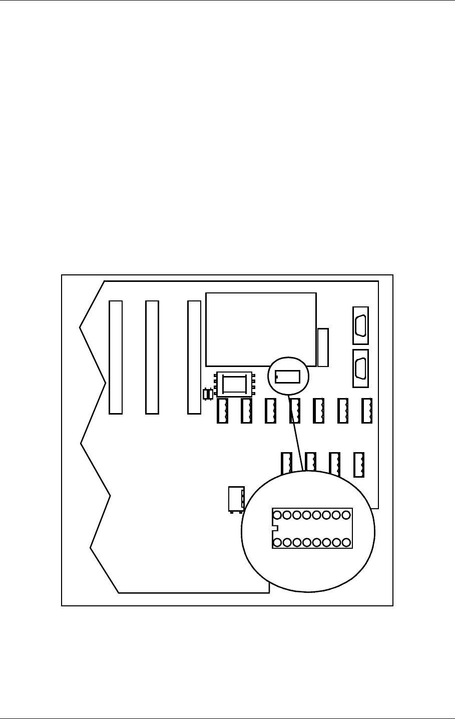
©1999 Navia Aviation AS 21464-5 Tests and adjustments
USER MANUALNORMARC 7050
MARKER BEACON
7-1
7 Tests and adjustments
7.1 Preparations
Terminate the RF OUT terminal with a 50Ω load (antenna or dummy). The transmitters are
factory adjusted to 2 watt output power. Let both transmitters run for ½ hour at this power to
achieve a stable working temperature before any fine tuning is carried out.
7.2 Configuration settings
Follow this procedure to set the configurations in the Marker Beacon according to desired sys-
tem configuration.
7.2.1 General Configuration
The static control strap on the Connection interface board sets hardware configuration,
remote access configuration and shutdown configuration. Figure 7-1 shows where the static
control strap is located on CI 1376.
Figure 7-1 Location of Static Control Strap on CI 1376
Set the configuration for the MB according to Table 7-1.
DIG PORT A DIG PORT B DIG PORT C DIG PORT D
CI 1376
PB 1378
REMOTE
CONTROL
LINE
TEMP
OUTDOOR
TEMP
INDOOR
AC LEVEL ANA CHA1 ANA CHA2 ANA CHA3
REMOTE RMM
RS232
REMOTE CONTOL
RS232
CONFIGURATION
S1
S2
S3
S4
S5
S6
S7
S8
CONFIGURATION
S1
S2
S3
S4
S5
S6
S7
S8
HBK797/1
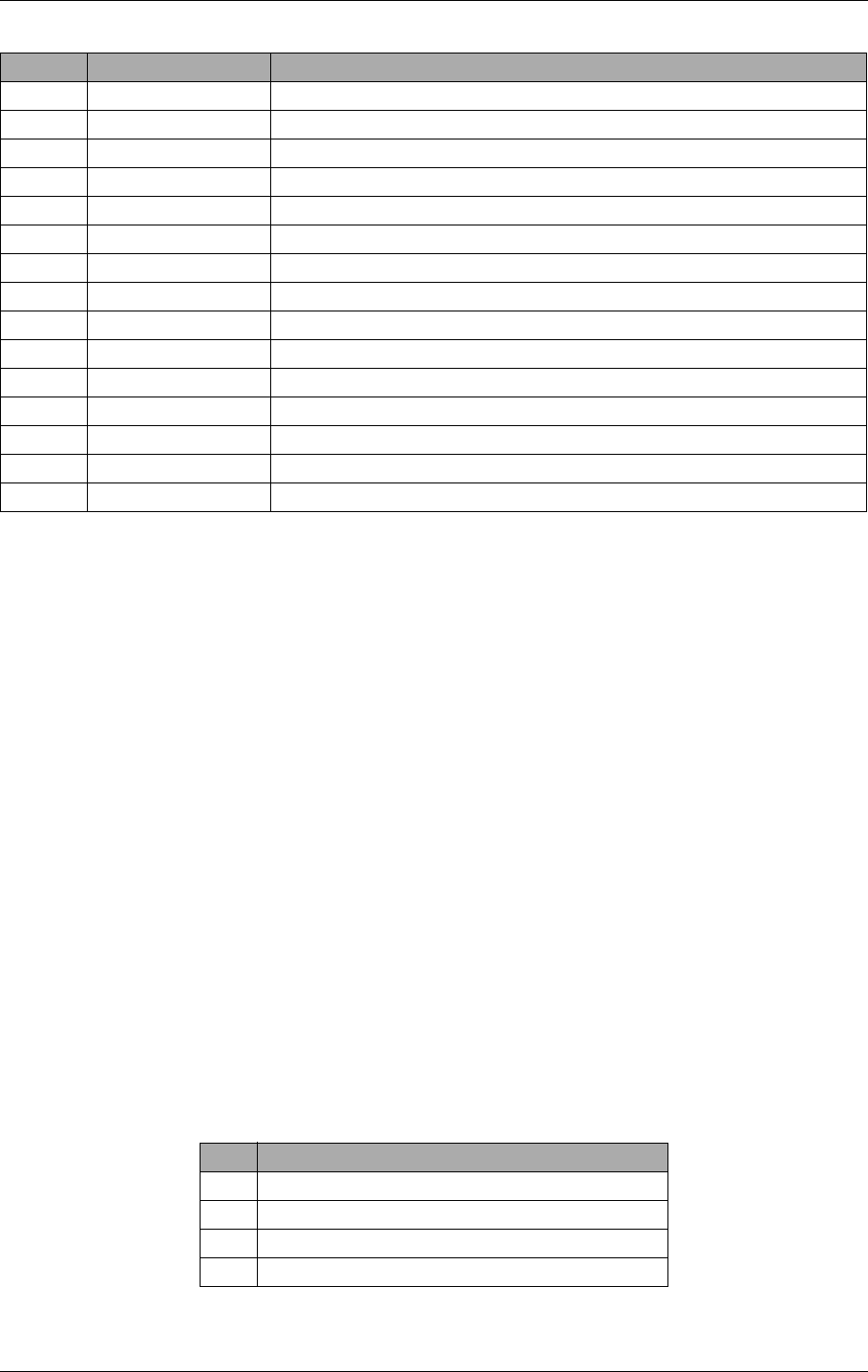
USER MANUAL
7-2
21464-5
NORMARC 7050
MARKER BEACON
Tests and adjustments ©1999 Navia Aviation AS
.
Table 7-1 MB Configuration settings
S1 and S3 will decide the model (NM 7050 A, B, C or D) and show up in the Link Status win-
dow in the RMM program and the Initial Window in the LCD menu. A disagreement between
the settings and the actual number of modules will cause a MAINTENANCE WARNING on the
Front Panel and an ERROR in the Maintenance window.
With S2 = IN the ACCESS GRANT switch on the Remote Control will have no effect. You may
still acquire ACCESS LEVEL 2 and 3 on the RMM remote port if the settings of S6 and S7 per-
mits.
S4 decides weather lost communication with the Remote Control will cause shutdown (no TX
to air) or not.
S5 instructs the transmitter control software weather a failed standby transmitter will be shut
down or continue to transmit.
S6 and S7 decides the highest ACCESS LEVEL permitted on the RMM remote port. All access
levels are available on the RMM local port regardless of S6 and S7.
7.2.2 Setting inner, outer or middle marker
To configure the beacon for outer, middle or inner marker set the straps (S1-S4) on the trans-
mitter board(s) according to Table 7-2.
Table 7-2 Marker function configuration
Strap no State Function
S1 Strap IN 2 power supplies (NM 7050 B/D)
Strap OUT 1 power supply (NM 7050 A/C)
S2 Strap IN Access Grant disabled
Strap OUT Access Grant enabled
S3 Strap IN 2 monitor units (NM 7050 C/D)
Strap OUT 1 monitor unit (NM 7050 A/B)
S4 Strap IN Lost contact with remote control will NOT cause shutdown
Strap OUT Lost contact with remote control will cause shutdown
S5 Strap IN Standby transmitter failure will NOTcause shutdown
Strap OUT Standby transmitter failure will cause shutdown
S6 Strap IN Access level 2 on RMM remote port enabled
Strap OUT Access level 2 on RMM remote port disabled
S7 Strap IN Access level 3 on RMM remote port enabled
Strap OUT Access level 3 on RMM remote port disabled
S8 Should always be left open.
Strap Function with strap in
S1 Beacon is INNER marker
S2 Beacon is MIDDLE marker
S3 Beacon is OUTER marker
S4 Beacon is FAN marker
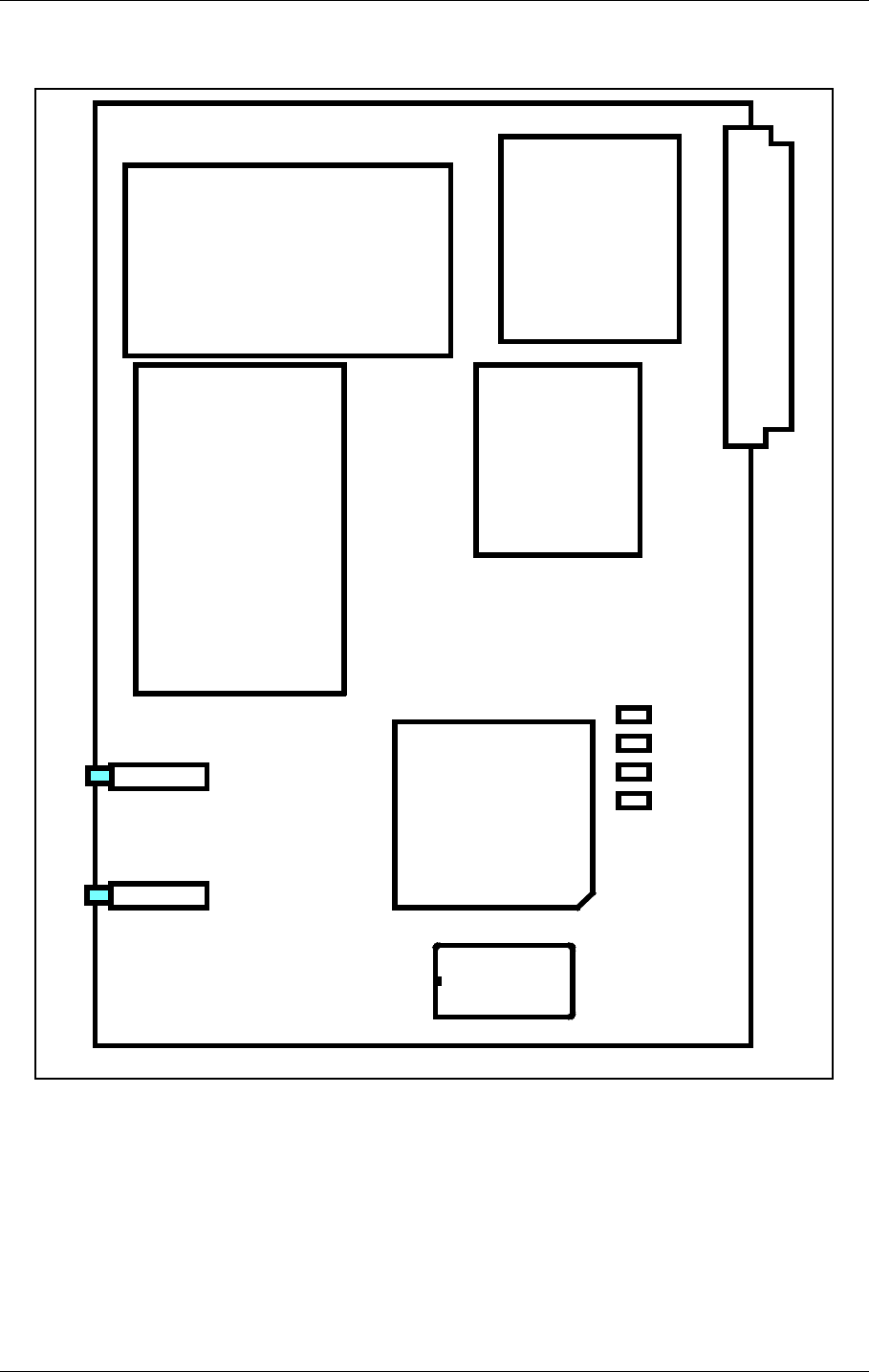
©1999 Navia Aviation AS 21464-5 Tests and adjustments
USER MANUALNORMARC 7050
MARKER BEACON
7-3
Figure 7-2 shows where the straps are located on the transmitter board(s).
.
Figure 7-2 Location of Marker Beacon type straps on transmitter board
7.2.3 Remote Control Interface (CI 1210)
The transmission medium (telephone line (FSK modem) or RS 232) to the Remote Control
can be selected by link straps S700 and S701 on the MO 1374A module in MON 1 position:
S1
S2
S3
S4
TX 1373
HBK798/1
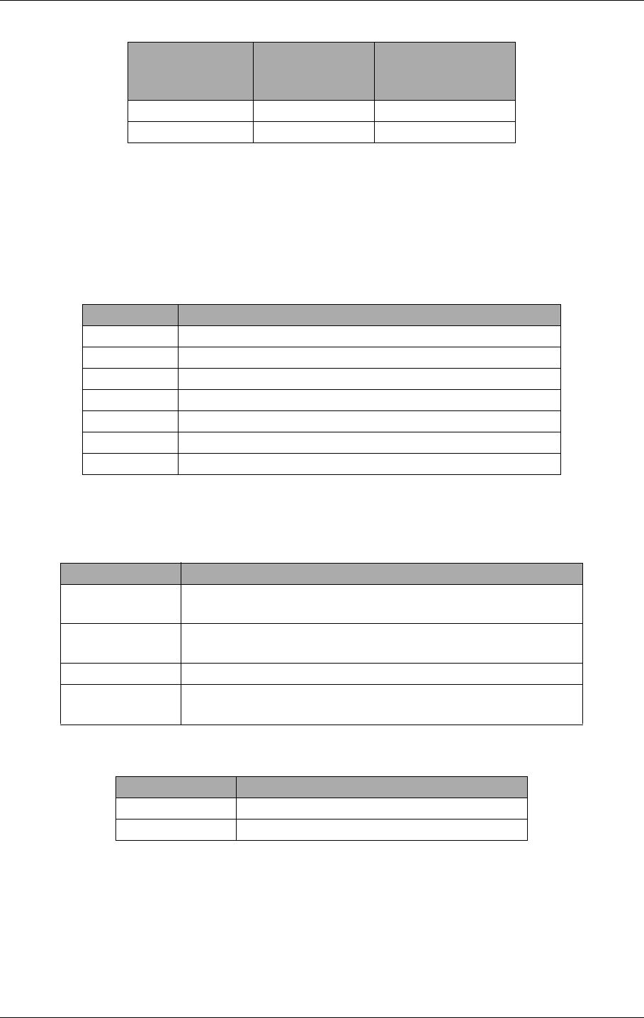
USER MANUAL
7-4
21464-5
NORMARC 7050
MARKER BEACON
Tests and adjustments ©1999 Navia Aviation AS
7.2.4 Remote Control configuration
The Aural Alarm / Warning functions and transmission medium (telephone line or RS 232) in
the Remote Control can be selected by link straps:
The strap links S6 to S12 will give Aural Warning for the following warning parameters when
connected::
Warning reset (Silence):
Buzzer:
Telephone Line / RS 232 / TTL logic:
S700 pins con-
nected S701 pins con-
nected Function
1-2 1-2 RS 232
3-4 3-4 Telephone line
Strap Warning Parameter
S6 Standby Alarm (Hot Standby racks only)
S7 Parameter Warning
S8 Ident Warning
S9 Battery Warning
S10 Standby on Air
S11 Monitor Disagree Warning
S12 Maintenance Warning
Strap Function
S1 in Silence on Remote Control resets Remote Control buzzer
only
S1 out Silence on Remote Control resets both Remote Control
and Slave Panel buzzer
S5 in Silence on Slave Panel resets Slave Panel buzzer only
S5 out Silence on Slave Panel resets both Remote Control and
Slave Panel buzzer
Strap Function
S4 in Buzzer connected
S4 out Buzzer disconnected
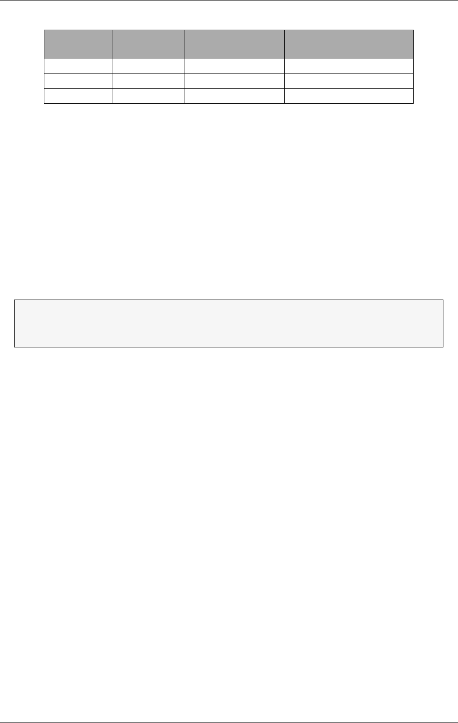
©1999 Navia Aviation AS 21464-5 Tests and adjustments
USER MANUALNORMARC 7050
MARKER BEACON
7-5
7.3 Adjustment points
The adjustment points are shown in Figure 7-3 and explained below. The figure shows a fully
equipped system, NM 7050D, see chapter 3 for configuration details:
1. Battery charging voltage (nom 27.4V@20°C)
1. Bias for power transistor (use factory settings)
1. Battery protection cut-off voltage (nom. 22V)
1. Tx Detected Rf level (nom. 2.5V@4W carrier)
1. Monitor RF level (nom. 3V@nominal output power)
1. Monitor frontend input filter centre frequency (use factory settings)
2. Real time clock fine tuning(use factory settings)
S2 pins con-
nected S3 pins con-
nected Function Input used on MB 1346A
1-2 1-2 Telephone line P9 Line A and Line B
3-4 3-4 RS 232 J2 Alt. link
5-6 5-6 TTL logic Not supported
The adjustment points marked Use Factory Settings should not be touched.
The baseband level has to be adjusted at installation.
The other are factory pre-set but may be adjusted.
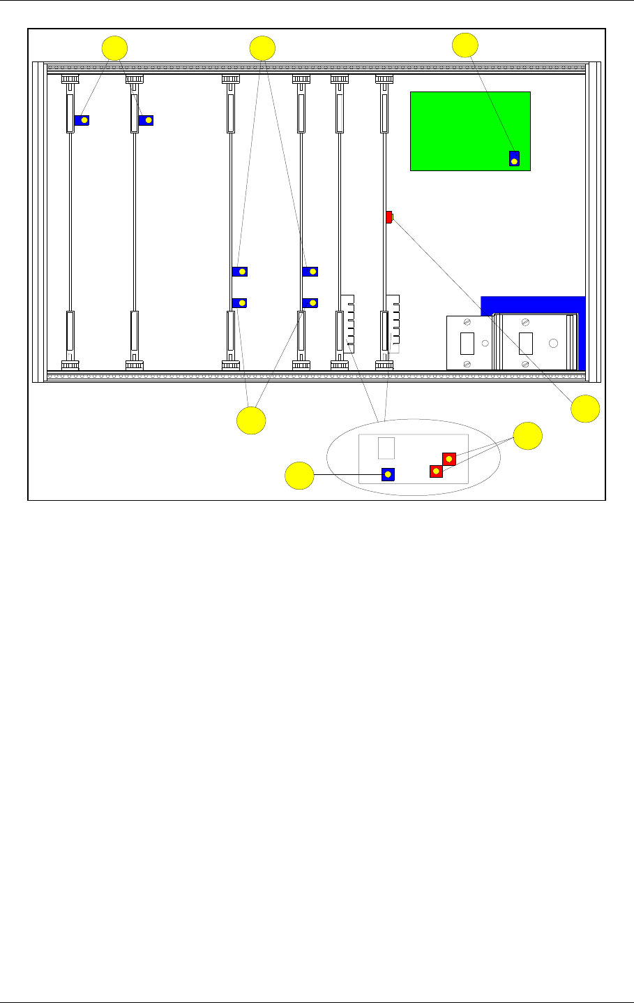
USER MANUAL
7-6
21464-5
NORMARC 7050
MARKER BEACON
Tests and adjustments ©1999 Navia Aviation AS
Figure 7-3 Adjustment points
7.4 Adjustments at installation
These procedures have to be carried out at installation in order to set up your equipment right.
7.4.1 Transmitter output power adjustment
This adjustment is most easily done with the RMM PC program but the local keyboard/display
may be used.
• Make sure the output signal RF OUT is terminated with a 50Ω load (antenna or dummy
load).
• If this is an Inner Marker make sure the external attenuator is installed.
• Start the RMM program on the PC (see chapter 10)
• Open the TX settings window, RF LEVEL for TX1 and TX2 are to be adjusted.
• Open the Maintenance window. RF LEVEL for TX1 and TX2 are to be watched.
•Set LOCAL mode with the REMOTE/LOCAL switch.
•Set MANUAL mode with the AUTO/MANUAL switch.
•Set TX1 to air with the CHANGEOVER button
•Adjust RF LEVEL in TX settings until you read the desired output power on RF LEVEL in
Maintenance.
• Check that you read the desired modulation depth in Maintenance.
•Set TX2 to air and repeat the two previous steps.
7.4.2 Monitor calibration
A
N
T
I
S
T
A
T
Shield box
Oscillator
123
4
5
6
7
HBK864/1
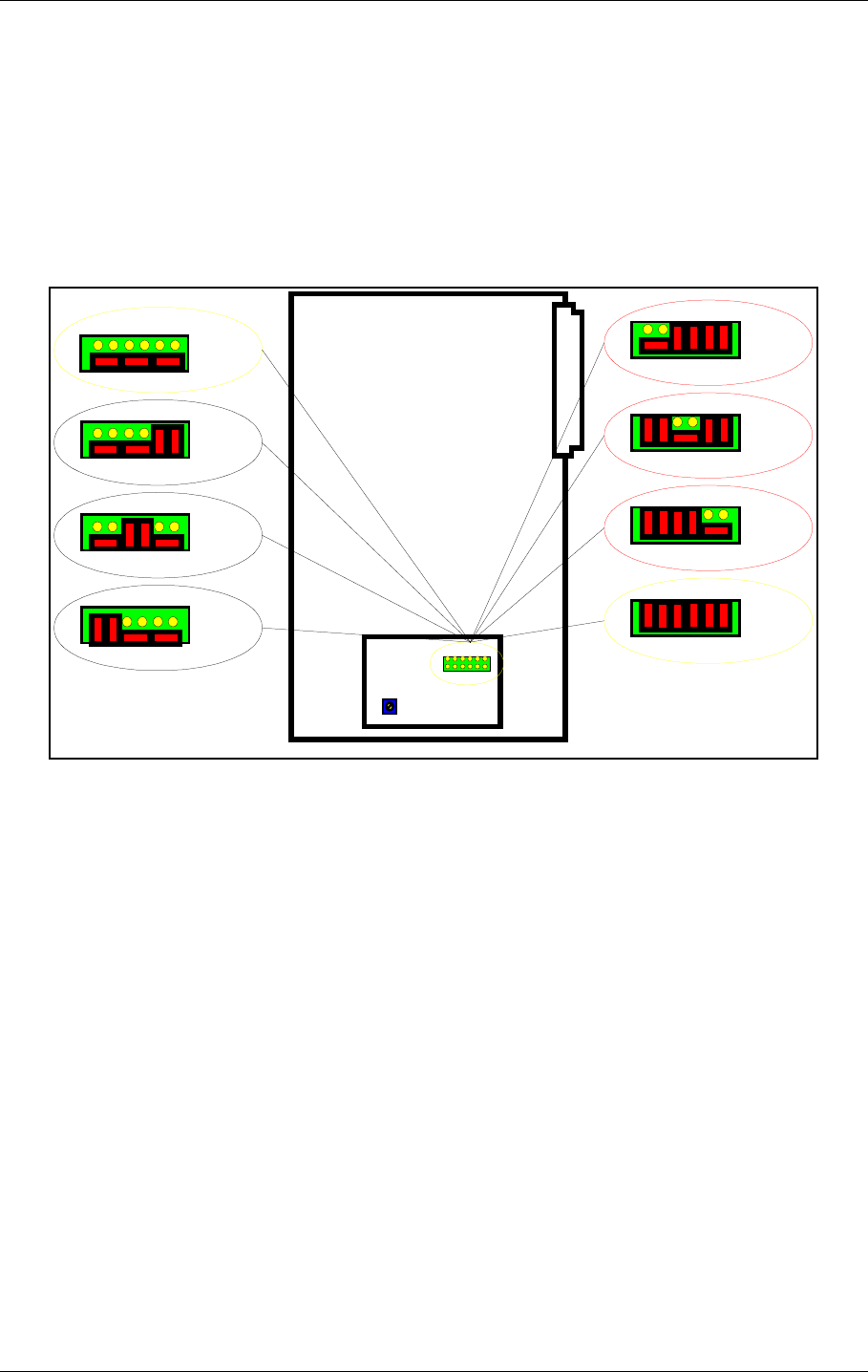
©1999 Navia Aviation AS 21464-5 Tests and adjustments
USER MANUALNORMARC 7050
MARKER BEACON
7-7
The software adjustments are most easily done with the RMM program, but may be carried
out from the front panel.
• This procedure requires that the output power is already adjusted
• Set the input attenuation straps on MO1374 according to the marker type. Start out with
22dB attenuation for outer marker, 18dB for middle marker and 12dB for inner marker.
• Watch the Monitor parameter RF LEVEL.
• Adjust the potentiometer R850 until RF LEVEL is 3V at the nominal output power.
• (Ref. fig. 7-4)
• If this is impossible to achieve, try another strap setting and readjust R850.
Figure 7-4 Input Signal attenuator
7.5 Other adjustments
These adjustments are normally not required, the factory settings should be sufficient.
7.5.1 Output power readout calibration
The CARRIER POWER parameter in the RMM Maintenance window is the internal wattmeter. It
is factory calibrated, but may be recalibrated by following this procedure. The software adjust-
ments are most easily done with the RMM program, but may be carried out from the front
panel.
• Connect a reference wattmeter to the output signal RF OUT.
• Set TX1 to air.
• Watch the maintenance parameter CARRIER POWER
• Adjust the TX settings parameter RF LEVEL until the watt meter shows 2W
• Check that the Maintenance parameter CARRIER POWER on TX1 is accurate to within 5%.
• If not, adjust the Carrier Power potentiometer on TX1 until the parameter shows 2.00W
• Repeat for 1W and 0.5W
• Repeat for TX2..
0dB
6dB
12dB
16dB
MO 1374
18dB
22dB
R850
28dB
34dB
HBK799/1

USER MANUAL
7-8
21464-5
NORMARC 7050
MARKER BEACON
Tests and adjustments ©1999 Navia Aviation AS
7.5.2 Battery protection cut-off voltage
The purpose of this circuit is to avoid deep discharge and thereby reduced life time of the
backup battery. For normal lead acid accumulators 22V (1.83V/cell) is a reasonable cut-off
voltage.
• Turn OFF the MAINS switch
• Connect a DC supply, preadjusted to the desired cut-off (REFERENCE) VOLTAGE and deacti-
vated, to the external charger input on CI 1376. This is called the REFERENCE SUPPLY.
• Connect a multimeter in DC volt position to the battery input.
• Turn the REFERENCE SUPPLY On.
• If you measure 0V on the battery adjust the potentiometer on PB1378 until the relay tog-
gles and you measure the REFERENCE VOLTAGE.
• If you measure the REFERENCE VOLTAGE, adjust the potentiometer until the relay discon-
nects and you measure 0V.
7.5.3 Battery charger voltage
The cells of a lead acid battery has an optimal voltage when they are fully charged. This volt-
age is greatly dependent on the temperature. The battery life time will decrease if this rule is
not followed. To meet the demand, the internal battery charger(s) in NM 7050, the PS 1375,
has a temperature compensated charging voltage.
Due to current limiting in PS 1375, a discharged battery will firstly be charged with a constant
current, ≈2A with one PS1375 and ≈6A with two PS1375. When the battery draws less than
the current limit, the battery will be charged with a constant voltage (UBATT). The factory set-
ting for the internal battery charger is:
UBATT20 = 27.6V @ 20°C with .
This is the normal final voltage for lead acid accumulators. If your batteries require a different
final voltage, the adjustment procedure is as follows:
• Turn the BATTERY switch OFF and have one TX on .
• Measure the environment temperature TENV (in °C)
• Compute the temperature deviation ∆T = TENV - 20°C
• Compute the new expected final voltage at your environment temperature as
• Adjust the potentiometer on PS1375 until you measure UBATT on the 27V test point on CI
1376.
ΤInner Marker uses an external 10 dB attenuator, use 0.2W, 0.1W and 50mW to
calibrate. CARRIER POWER is measured prior to the attenuator, but the soft-
ware will automatically compensate for the 10dB.
Example:
Your battery requires a final voltage of 26V at 20°C, and you have measured an envi-
ronmental temperature of 25°C. You should then adjust the charger to give
UBATT = 26 + (-0.04)(25 - 20) = 25,8 V
kU
T
mV
C
BATT
==
°
êú
∆
∆- 40
UU kTBATT BATT=+⋅20 ∆
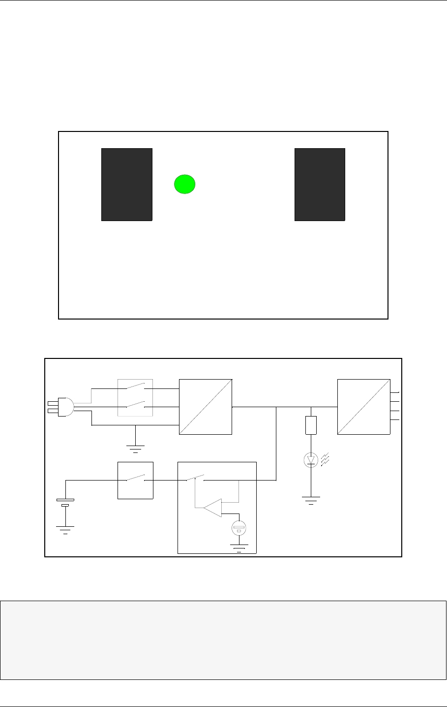
©1999 Navia Aviation AS 21464-5 Operation Main Cabinet
USER MANUALNORMARC 7050
MARKER BEACON
8-1
PART III OPERATION
8 Operation Main Cabinet
8.1 Power On/off
The power switches for MAINS and BATTERY are located on the lower right side of the cabinet
front (Figure 8-1). A lit POWER LED indicates that the system has power, the source may be
either mains or battery as shown in Figure 8-2.
Figure 8-1 The power switches and indicator
Figure 8-2 Simplified power diagram
ΤΤIf the BATTERY switch is OFF in normal mains power operation, the battery will not
be charged.
ΤIf the battery voltage drops below 22V, the internal battery protection circuitry will
disconnect the battery. The battery will not be reconnected until the mains power
returns to normal.
BATTERY MAINS
OFF
ON
POWER
ON
OFF
HBK865/1
AC
DC
MAINS
BATTERY
POWER
Voltage
reference
Battery protection
Primary 28 Volts DC DC
DC
HBK866/1
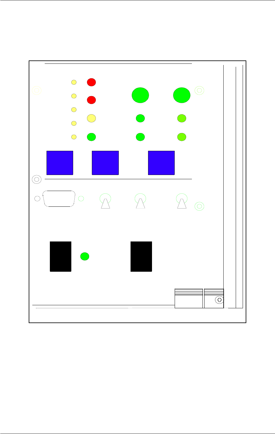
USER MANUAL
8-2
21464-5
NORMARC 7050
MARKER BEACON
Operation Main Cabinet ©1999 Navia Aviation AS
8.2 Local Control Operation
The Local Control is the lower half of the control section on the cabinet front. This section is
used to control the transmitters and the operational modes of the Marker Beacon (MB)
besides showing the system status via Light Emitting Diodes (LED's).
Figure 8-3 LC1377 on front panel
8.2.1 Glossary
AUTOMATIC When the MB is in automatic mode of operation, any detected alarm(s)
will lead to either CHANGEOVER or SHUTDOWN.
MANUAL When MB is in manual operation, the MB state will not change if
alarm(s) is detected.
INTERLOCK When an MB is in active interlock mode, the MB will turn off active trans-
mitter and not allow them to be turned on before the interlock condition
is removed. This signal overrides manual mode of operation.
BATTERY MAINS
MAIN
OFF
ON
TX TO AIR
LOCAL RS232
POWER
ON
OFF
LOCAL
REMOTE
MANUAL
AUTO
STBY
DISAGR
PARAM
MAINT
BATT
NORMAL
ON/
OFF
CHANGE
OVER
SERVICE
WARNING
ALARM
TX1
PROTECT
WRITE
TX1/
TX2
TX2
HBK 800-1
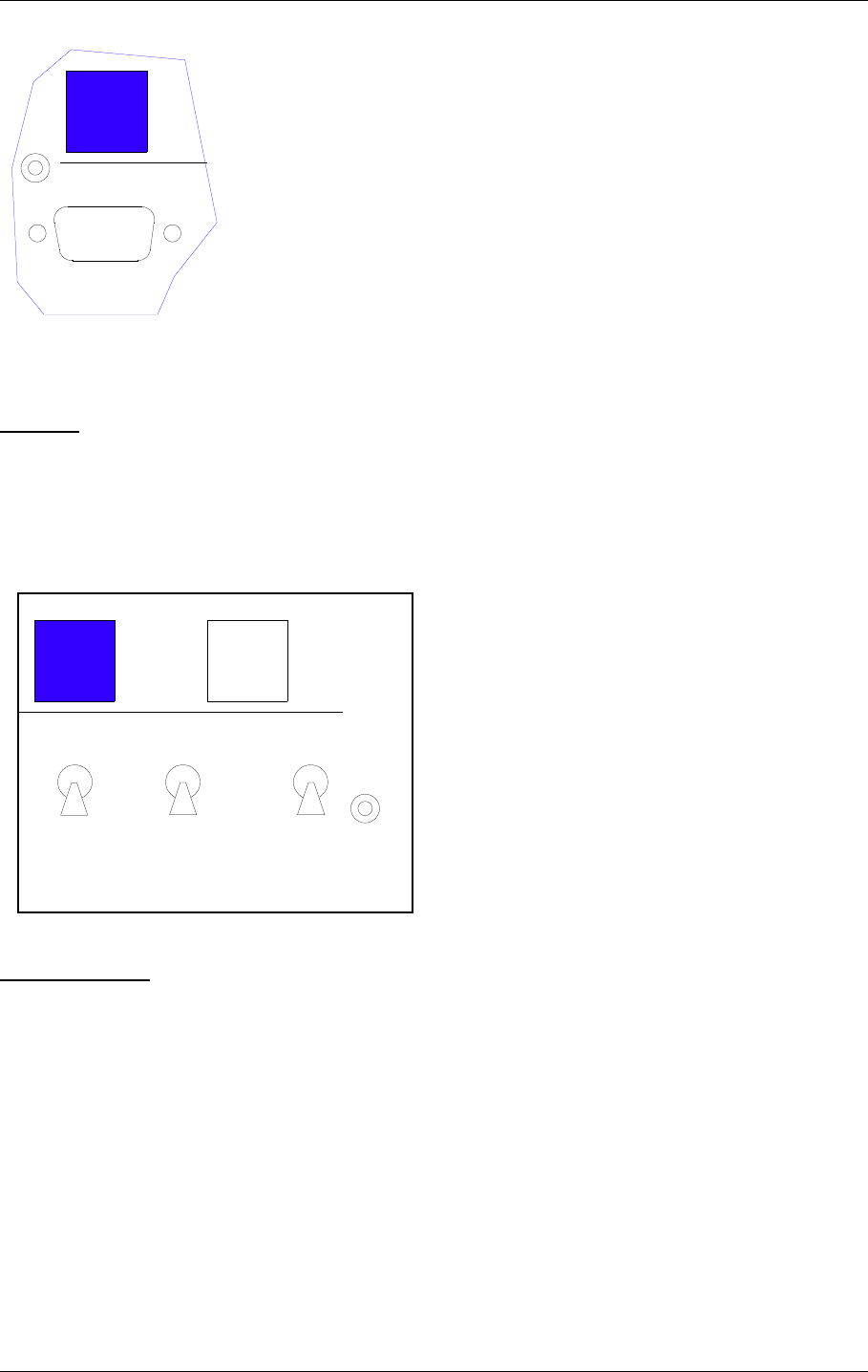
©1999 Navia Aviation AS 21464-5 Operation Main Cabinet
USER MANUALNORMARC 7050
MARKER BEACON
8-3
8.2.2 Pushbuttons
ON/OFF
Used to:
• Toggle the MB on/off.
Valid when:
• The LOCAL/REMOTE switch must be in LOCAL position.
• The INTERLOCK signal is NOT ACTIVE if the MB is configured for Interlock.
CHANGEOVER
Used to:
• Toggle the transmitters between TX1/TX2 as the active transmitter(s).
Valid when:
• The LOCAL/REMOTE switch is in LOCAL position.
• The MB is ON when the MANUAL/AUTO switch is in AUTO position
LOCAL RS232
ON/
OFF
HBK801/1
LOCAL
REMOTE
MANUAL
AUTO
CHANGE
OVER
PROTECT
WRITE
TX1/
TX2
HBK802/1
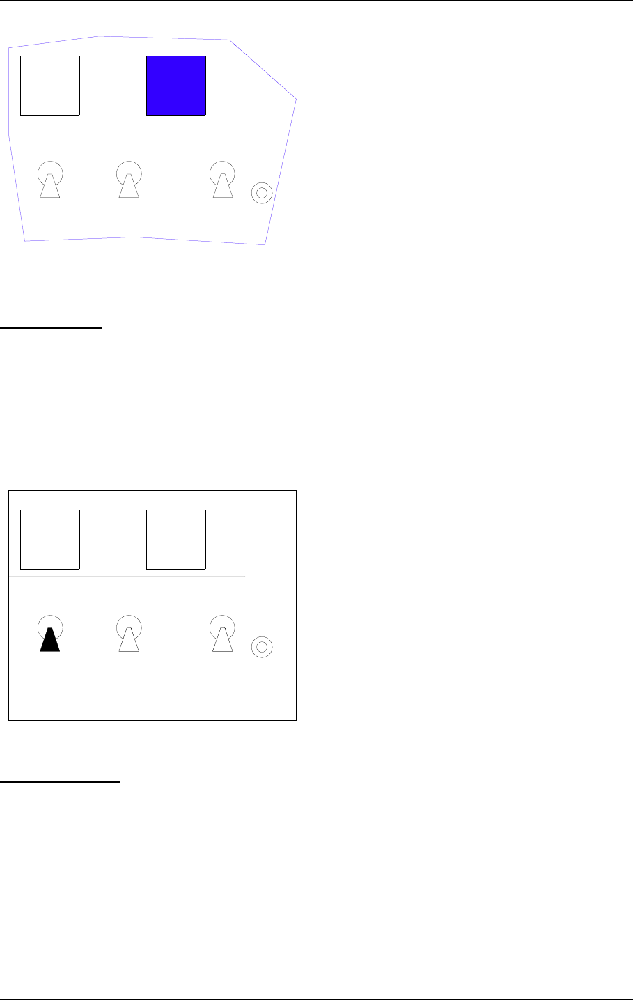
USER MANUAL
8-4
21464-5
NORMARC 7050
MARKER BEACON
Operation Main Cabinet ©1999 Navia Aviation AS
MAIN SELECT
Used to:
• Toggle between TX1/TX2 as the main transmitter and standby transmitter.
Valid when:
• The LOCAL/REMOTE switch is in LOCAL position.
8.2.3 Switches/Switchlocks
LOCAL/REMOTE
Used to:
LOCAL
REMOTE
MANUAL
AUTO
CHANGE
OVER
PROTECT
WRITE
TX1/
TX2
HBK803/1
LOCAL
REMOTE
MANUAL
AUTO
CHANGE
OVER
PROTECT
WRITE
TX1/
TX2
HBK804/1
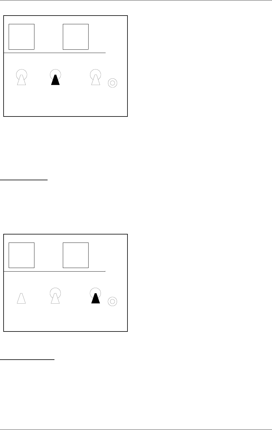
©1999 Navia Aviation AS 21464-5 Operation Main Cabinet
USER MANUALNORMARC 7050
MARKER BEACON
8-5
• Select between LOCAL and REMOTE mode of operation. REMOTE mode of operation will
inhibit use of the local push buttons and the local serial communication port for entering
RMS ACCESS LEVEL 2 and 3. LOCAL mode of operation will inhibit use of the remote control
push buttons (ON/OFF, CHANGEOVER) and the use of the remote serial communication
port.
MANUAL/AUTO
Used to:
• Select between AUTOMATIC and MANUAL mode of operation.
Valid when:
• The LOCAL/REMOTE switch is in LOCAL position.
WRITE PROTECT
Used to:
• Prevent changing of alarm limits and other parameter adjustments. Setting this switchlock
will prevent entering of access level 3.
Valid when:
•Always.
LOCAL
REMOTE
MANUAL
AUTO
CHANGE
OVER
PROTECT
WRITE
TX1/
TX2
HBK806/1
LOCAL
REMOTE
MANUAL
AUTO
CHANGE
OVER
PROTECT
WRITE
TX1/
TX2
HBK805/1

USER MANUAL
8-6
21464-5
NORMARC 7050
MARKER BEACON
Operation Main Cabinet ©1999 Navia Aviation AS
8.2.4 System Status Indications
SERVICE
Used to :
• Indicate that the MB is currently in SERVICE mode of operation. This will also set the
remote control to alarm state.
Activated by :
•RMS in ACCESS LEVEL 2 or 3, or
• The LOCAL/REMOTE switch is in LOCAL position, or
• The MANUAL/AUTO switch is in MANUAL position, or
•MANUAL mode entered from RMS, or
• Mismatch between the WRITE PROTECT switch and configuration strap setting on U6
(strap position 6-15).
ALARM
Used to:
• Indicate that the MB has detected an alarm condition.
ΤIf the LOCAL/REMOTE switch is in REMOTE position, an RMM operator may alter the
MANUAL/AUTO mode without this being reflected on the physical switch.
STBY
DISAGR
PARAM
MAINT
BATT
NORMAL
SERVICE
WARNING
ALARM
HBK824/1
STBY
DISAGR
PARAM
MAINT
BATT
NORMAL
SERVICE
WARNING
ALARM
HBK825/1

©1999 Navia Aviation AS 21464-5 Operation Main Cabinet
USER MANUALNORMARC 7050
MARKER BEACON
8-7
Activated by:
• One or more alarms present
NORMAL
Used to :
• Indicate that no alarm conditions are detected by the MB.
Activated by :
• No alarms present.
WARNING
Used to :
• Indicate that the MB has detected one or more warning conditions.
Activated by :
• Warning condition(s) detected by RMS.
PARAMETER WARNING
Used to :
• Indicate that there are one or more monitor parameter warnings present. The warnings
from the Monitor 1/Monitor 2 are voted before displayed.
Activated by :
• One or more monitor parameters outside the warning limits.
MONITOR DISAGREE (MODEL 7050 C AND D ONLY)
STBY
DISAGR
PARAM
MAINT
BATT
NORMAL
SERVICE
WARNING
ALARM
HBK826/1
STBY
DISAGR
PARAM
MAINT
BATT
NORMAL
SERVICE
WARNING
ALARM
HBK827/1

USER MANUAL
8-8
21464-5
NORMARC 7050
MARKER BEACON
Operation Main Cabinet ©1999 Navia Aviation AS
Used to :
• Indicate that Monitor 1 and Monitor 2 disagree on which parameters that are in alarm
state.
Activated by :
• Difference in monitor 1/monitor 2 alarm detection.
BATTERY WARNING
Used to :
• Indicate that the MB is running using the 24V battery.
Activated by :
• Loss of mains for charging the 24V battery.
MAINTENANCE WARNING
Used to :
• Indicate that one or more of the maintenance parameters warnings detected.
Activated by :
• One or more maintenance parameters faulty or outside limits.
STANDBY TRANSMITTER ON AIR
Used to :
• Indicate that the RF relay directs the standby transmitters to the antenna and the main
transmitters to the dummy load.
Activated by :
• TX to air position differs from transmitter main select.
8.3 Local Keyboard/display Operation
The Local Keyboard and Display is a simple interface to the RMM system. This means you
have access to most of the RMM functionality without the need of a PC.
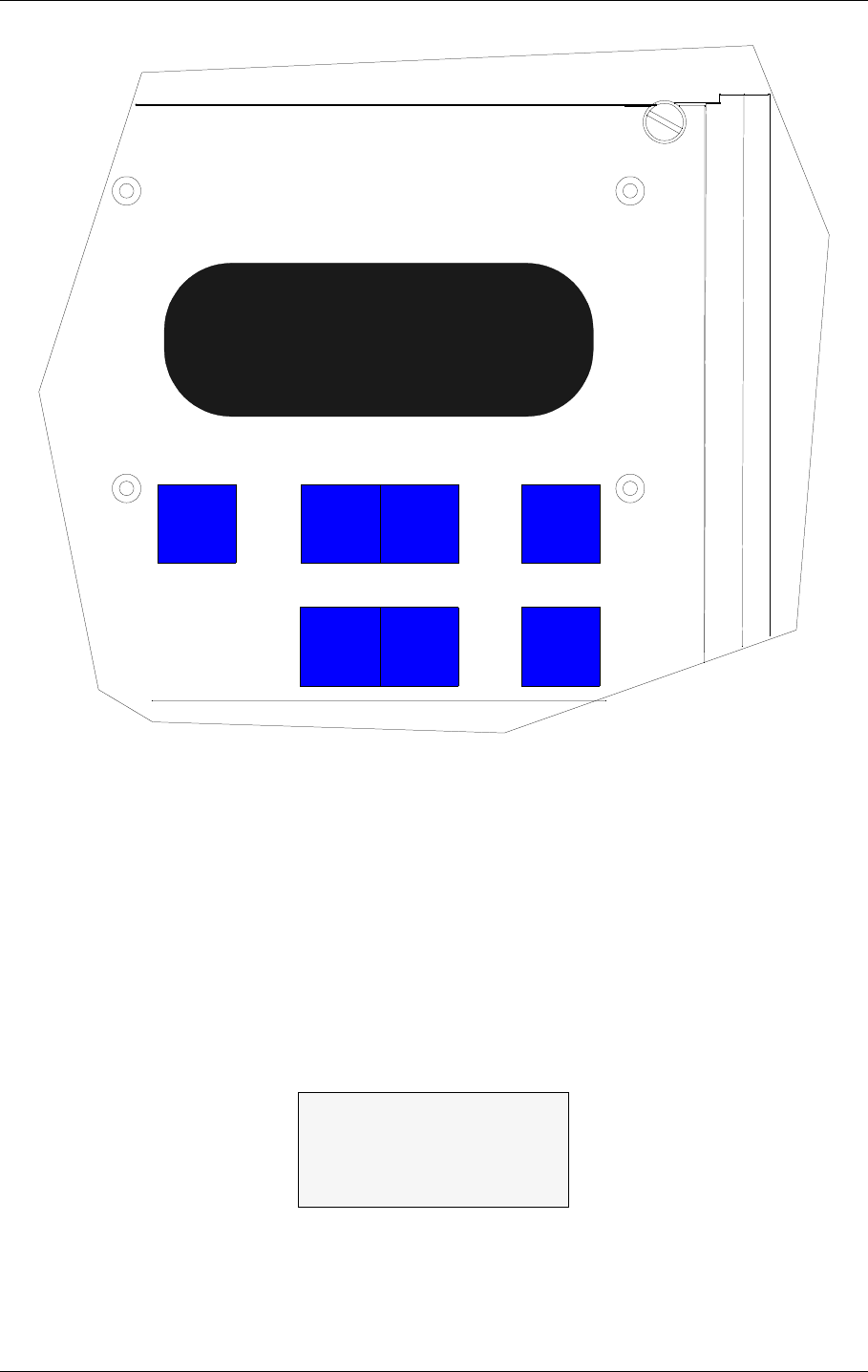
©1999 Navia Aviation AS 21464-5 Operation Main Cabinet
USER MANUALNORMARC 7050
MARKER BEACON
8-9
Figure 8-4 Local keyboard and Display
8.3.1 The menu structure
The front panel menu system includes a 20x4 character LCD with 7 dedicated push-button
keys. The system is organised as a top-down menu tree-structure where the main menu is the
default entering point.
The main menu screen has three menu-options. The options are divided into the three ACCESS
LEVELS; LEVEL 1 with basic readout functions, LEVEL 2 with test and control functions and LEVEL
3 with permanent system parameter settings and configuration changes.
Figure 8-5 The top level main menu screen.
8.3.2 Handling the different menu screens.
The menu system consists of five basic screen types; menu screens, readout screens, toggle
>Read syst para L1
Local settings L2
Syst settings L3
ESC PREV NEXT ENTER
_+QUICK
READ
HBK807/1

USER MANUAL
8-10
21464-5
NORMARC 7050
MARKER BEACON
Operation Main Cabinet ©1999 Navia Aviation AS
screens, input/storing screens, and the quick read screens.
8.3.2.1 The menu screen
The menu screen is controlled by the key-buttons : PREV , NEXT , ENTER and ESC.
The menu options are formatted as a long list where each option holds one character line. If a
menu screen includes more than four options, a small arrow-indicator will be displayed in the
lower right corner. This informs the user that more than four menu options are available. The
blinking arrow cursor left to the menu text is controlled by the NEXT and PREV keys. The
ENTER key activates the menu options left to the arrow-cursor.
The ESC key brings the user one menu-level upwards or back in the menu-tree-structure.
The menu scrolls down if the user pushes the NEXT key when the arrow-cursor is at the lower
line and the arrow indicator is displayed in the lower right corner. The menu will in the same
way scroll upwards by pushing the PREV-key in a corresponding situation.
8.3.2.2 The readout screen
The readout screens display the various monitor and maintenance parameter readings. The
screens are entered by stepping through the menu options. The ESC key brings the user back
to the previous menu screen again. The parameter readings are continuously updated..
Figure 8-6 A typical readout screen: Monitor Depth of Modulation.
8.3.2.3 The toggle screens
The toggle screens offer the user to choose between two or more options. The options text is
enclosed by two blinking square-brackets. The plus «+» and minus «-» keys step through the
various options. The ENTER key activates the chosen toggle option. The ESC keys leaves
the screen without activating any of the options.
Figure 8-7 A typical toggle screen: Local RS232 baudrate
8.3.2.4 Input/Store screen
The user can change the various parameter alarm and warning settings in the input/storing-
screens. A virtual cursor is controlled by the PREV and NEXT keys. An input field number will
blink if the cursor is moved to the correct position. The blinking limit values can now be
changed by pushing the plus «+» and minus «-» keys. If the input field is digital, the valid
options will be FALSE and TRUE when the plus «+» and minus «-» keys are pushed.
When all the input numbers in the screen are changed to the preferred new values, the cursor
must be moved to the STORE-field in the upper left corner. When the cursor is placed at this
readout M1 Rf Mod.
Mod. : 95.2%
Al U 99.0% L 91.0%
Wa U 98.0% L 93.0%
Set bitrate Local
[ 9600 ]

©1999 Navia Aviation AS 21464-5 Operation Main Cabinet
USER MANUALNORMARC 7050
MARKER BEACON
8-11
STORE-field, the brackets will start blinking. The ENTER key will now store the new values on
the screen in the MB. The ESC key leaves the screen unchanged.
Figure 8-8 A typical input/store screen: Monitor Depth of Modulation
8.3.2.5 The quick read screen
The quick read screens are accessed by pushing the QUICK READ key. The key toggles
between the original menu tree and the quick read screens. The QUICK READ button can be
pushed at all times, not changing the original menu screens. The quick read screens include
only the basic monitor readings and a few system voltages. The PREV and NEXT keys step
through the quick read screens.
Figure 8-9 The quick read screen for monitor 1.
8.3.3 The access levels
The level 3 menu options must be entered by typing a 4 character password. The level 2
menu can be entered as an ordinary menu option.
8.3.3.1 Level 2
To enter the level 2 menu option, the front panel switches must be in the LOCAL and MAN-
UAL positions. The remote panel access switch must also be in ACCESS position. The user is
denied access if the switches are not correctly set.
Figure 8-10 An access denial screen: Switch in REMOTE position.
8.3.3.2 Level 3
To enter the level 3 menu option, the front panel switches must be as for level 2 access. In
addition the WRITE PROTECT switch must be in ACCESS position. The user must key a 4
character password to enter level 3 access. The access-screen is operated similarly to an
input/store-screen. The blinking cursor is moved by the PREV and NEXT keys. A blinking
input field is changed by the plus «+» and minus «-» keys.
When the correct password is entered, the cursor must be moved to the <LEVEL 3 ACCESS>-
field. The brackets will then start blinking. The ENTER key will now bring the user to the level
<store> M1 Rf Mod.
Mod. : 94.8%
Al U: 99.0% L 91.0%
Wa U: 98.0% L 93.0%
-QR- Monitor 1
Rf : 3.0v
Mod.: 94.9%
Keying: On
Local switch on
Front panel in
REMOTE position
Push <ESC>

USER MANUAL
8-12
21464-5
NORMARC 7050
MARKER BEACON
Operation Main Cabinet ©1999 Navia Aviation AS
3 options. The ESC key leaves the screen back to the main menu..
Figure 8-11 Level 3 access screen
8.3.3.3 Leaving the access levels
If the user enters LEVEL 2 or 3, an extra menu line is added in the main menu screen. This is a
leave current access level option. The user must enter this menu option to quit the current
access level - typically when leaving the MB.
The access levels are also left when the front panel switches are changed to an illegal posi-
tion. ( e.g. switch in REMOTE position ).
Figure 8-12 The top level main menu screen: User in level 3 access.
8.3.4 Function listing
The menu system includes the following functionality.
8.3.4.1 Level 1
• Readout of all the monitor values, warning and alarm limits.
• Readout of all the maintenance values and warning limits.
• Readout of all the delays.
• Readout of all the TX1 and TX2 configurations.
8.3.4.2 Level 2
• TX1 and TX2 : Using pre-programmed test settings.
• Communications.
8.3.4.3 Level 3
• Settings of all the monitor warning and alarm limits.
• Settings of all the maintenance warning limits.
• Settings of all the delays.
• Settings of all the TX1 and TX2 configurations.
• Communications.
8.3.5 The menu tree
The top levels of the menu tree is shown in Figure 8-13.
LEVEL ACCESS 3
M M
M M
<level3 access>
>Read syst para L1
Local settings L2
Syst settings L3
Leave access 3
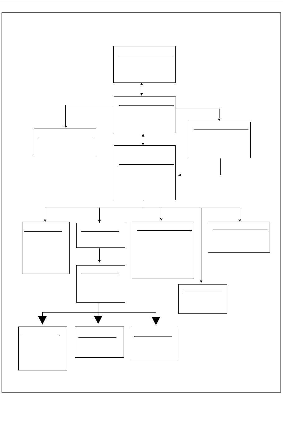
©1999 Navia Aviation AS 21464-5 Operation Main Cabinet
USER MANUALNORMARC 7050
MARKER BEACON
8-13
Figure 8-13 Menu system, Standard Menu
Top Menu
Normarc
- NM7050 -
Marker Beacon
Ver. X
Main Menu
> Read Syst. Para L1
Local Settings L2
Syst Settings L3
(Leave Access 2/3)
Read Syst. Para. &
Local Settings &
Syst Settings
> Mon Parameters
TX Configuration
Maint. val. & lim.
System Delays
Communications
Password Menu
LEVEL ACCESS 3
M M
M M
(Level 3 access)
Local Settings
> Reset hist. storage
Mon. Parameters
> M1 RF Level
M1 Mod Level
M1 Keying
M2 RF Level
M2 Mod Level
M2 Keying
TX configuration
> TX1 Config
TX2 Config
Maint. val. & lim.
> Transmitter 1 OK
Transmitter 2 OK
Power Supply 1 OK
Power Supply 2 OK
Monitor 1 OK
Monitor 2 OK
Conn. Interface OK
Communications
> Bitrate Local
Bitrate Remote
Init Modem
TX1 config
> TX1 Normal Set
TX1 Test1 set
TX1 Test2 set
Change Set
System delays
> Mon1 delay
Maint Delay
Maint user delay
TX1/2 Normal Set
> RF Level
Mod depth
Keying
Letter Length
Keyer Bits
TX1 Test 1/2 set
> RF Level
Mod depth
Keying
Change Set
Change tx1/2 set
[ Normal ]
<ESC>
(If selecting "syst settings"
while in level 1 or 2)
(If selecting "local settings")
(If password validated
to be OK)
Standard Menus
Note
:
Pressing <ESC> on the front
panel keyboard takes you up one
level in the menu hierarchy. If you
are on the top, the <ESC> key
takes you to the Main Menu.
Note
:
A dotted line below a menu
indicates that there are more
submenus availlable for each of
the current menu items.
Note
:
Access Level 1 gives readout only
Access Level 2 gives readout only
except for tx1/2 config. where the
user may alter the test settings and
changed set (while in level 2/3).
Access level 3 gives full edit for all
parameters.
Note
:
Menu item "communications"
shown only when in access level 3
H1121-1
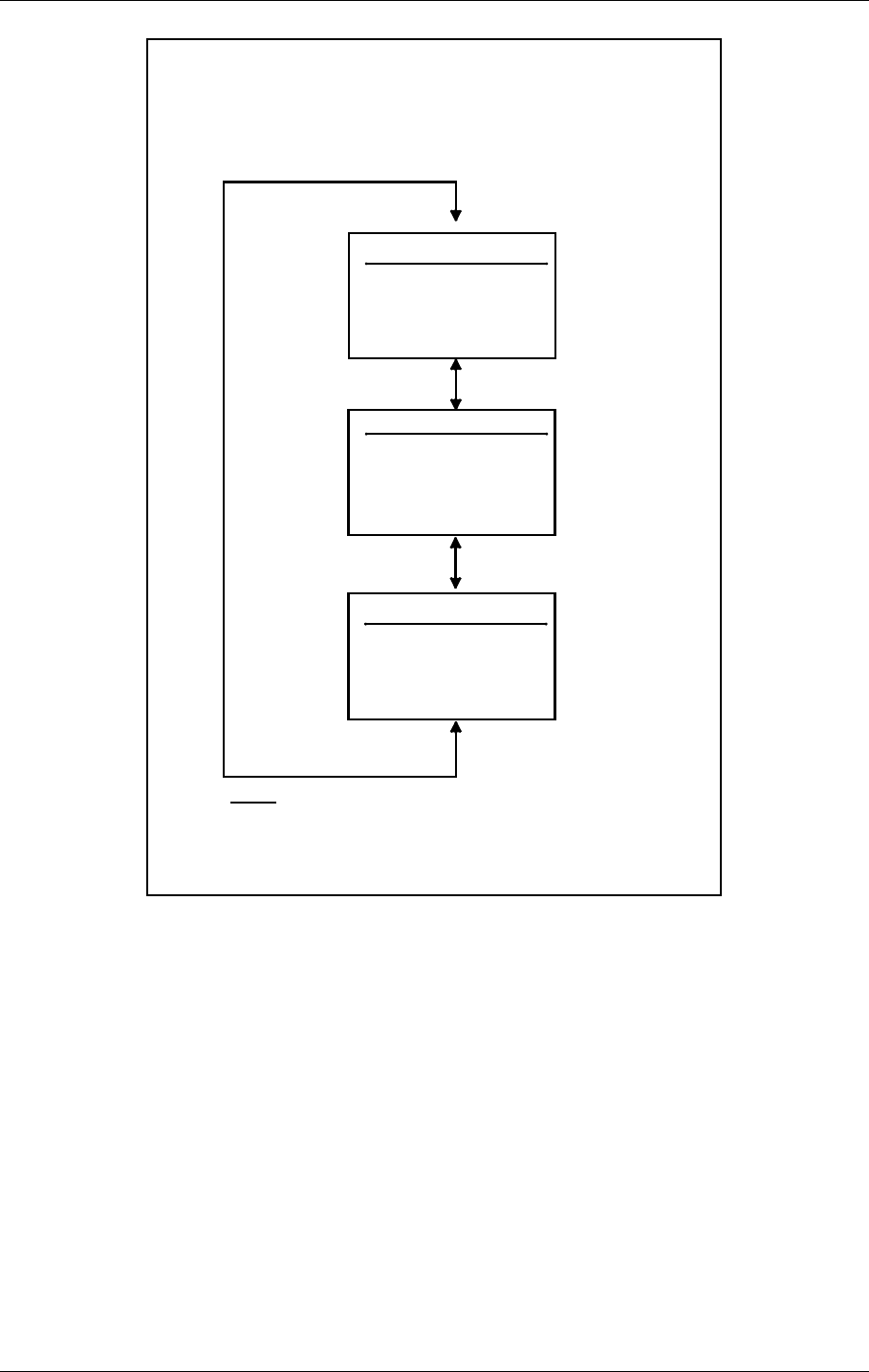
USER MANUAL
8-14
21464-5
NORMARC 7050
MARKER BEACON
Operation Main Cabinet ©1999 Navia Aviation AS
Figure 8-14 Quick Read Menu
Quick Read Mon 1
-QR- Monitor 1
RF: 3.0v
Mod: 95.1%
Keying: On
Quick Read Menus
:
Use the <QUICK READ> key to toggle
between the "standard menu" and the
quick read menus
Quick Read Mon 2
Quick Read Voltages
-QR- Voltages
V28P Voltage: 26.5v
V12P Voltage: 12.0v
V12N Voltage: -12.1v
Note:
Use <Next> and <Prev> keys to
navigate through the quick read menus
H1122-1
-QR- Monitor 2
RF: 3.0v
Mod: 95.1%
Keying: On
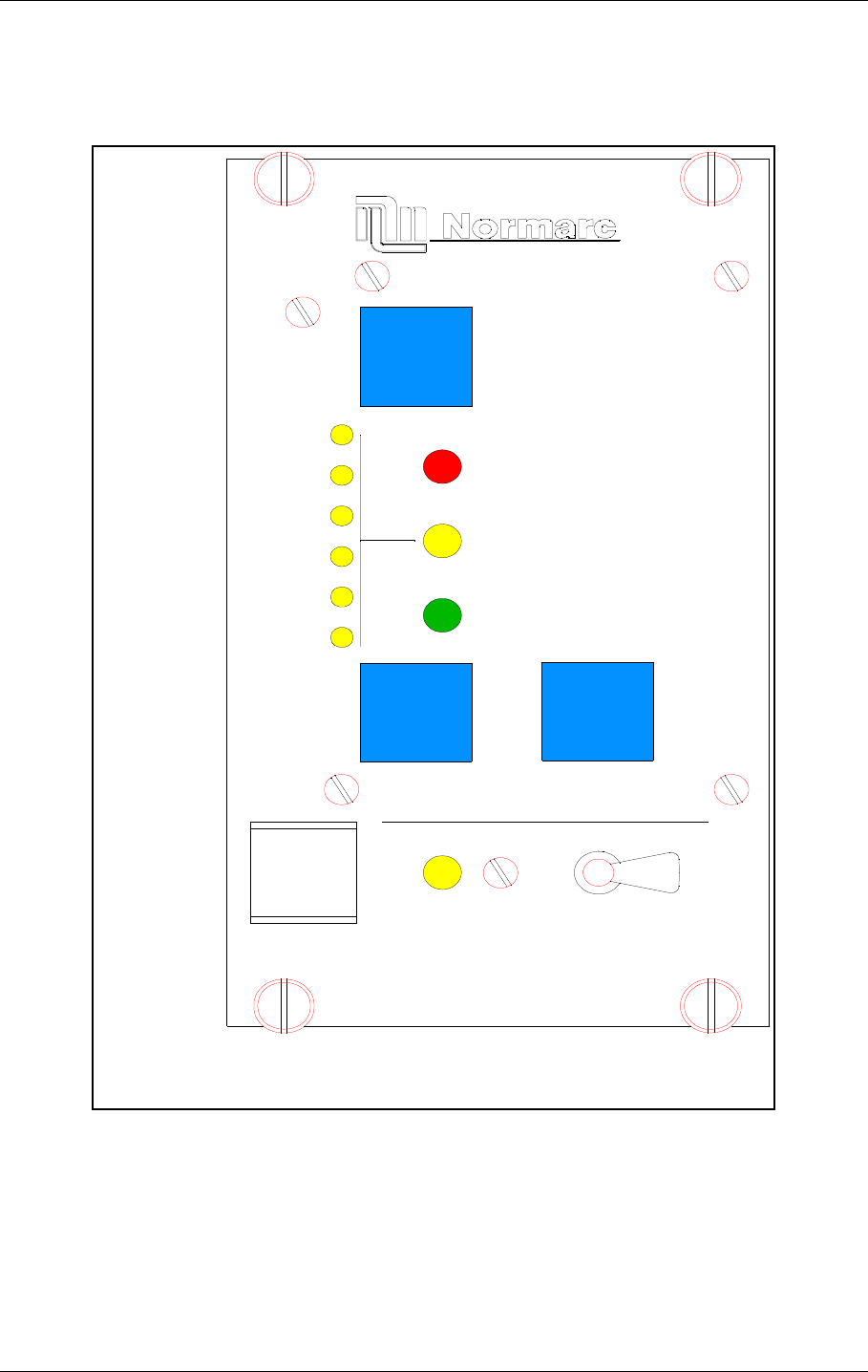
©1999 Navia Aviation AS 21464-5 Remote Control And Slave Operation
USER MANUALNORMARC 7050
MARKER BEACON
9-1
9 Remote Control And Slave Operation
9.1 Remote Control Operation
Figure 9-1 Remote Front panel
9.1.1 Glossary
INTERLOCK When an ILS is in active interlock mode (the interlock signal is an input to the
remote control), the ILS will turn off all active transmitters and not allow them to
be turned on before the interlok condition is removed. This signal overrides
RMM
ACCESS GRANT
MAINT
STBY
OFF
ON/
NORMAL
T
IDENT
ATB
ARAM
DISAGR
P
WARNING
ALARM
DENY
SILENCE
OVER
CHANGE
HBK808/1
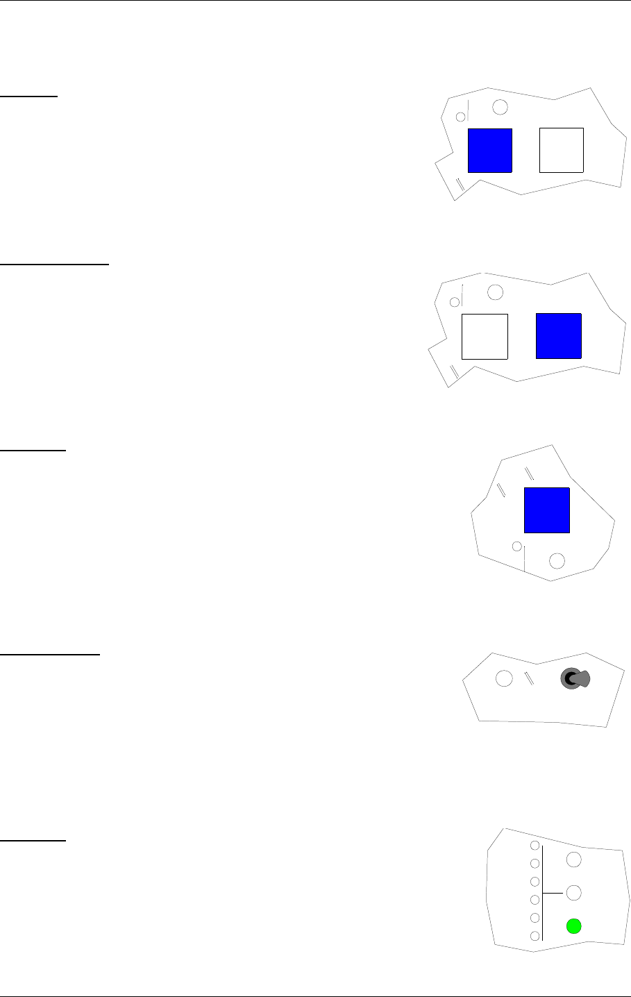
USER MANUAL
9-2
21464-5
NORMARC 7050
MARKER BEACON
Remote Control And Slave Operation ©1999 Navia Aviation AS
manual mode of operation.
9.1.2 Pushbuttons
ON/OFF
Used to:
• Toggle the MB on/off.
Valid when:
• The LOCAL/REMOTE switch must be in REMOTE position,
and
• The interlock signal is not active if the MB is configured for
interlock.
CHANGEOVER
Used to:
• Toggle the coax relay and transmitters between TX1/TX2
as the active transmitter(s).
Valid when :
• The LOCAL/REMOTE switch on the ILS is in REMOTE
position, and
• The MB is «on» when he MANUAL/AUTO switch is in
AUTO position.
SILENCE
Used to:
• Turn off the audio alarm on the remote control (caused by remote
status change from NORMAL to ALARM). Also used for lamp
test (all lamps are illuminated when this push-button is held
down).
Valid when:
•Always.
Switches
GRANT/DENY
Used to:
• Give access grant (access level 2/3) for RMS control of the MB
when the switch is in GRANT position.
Valid when:
• Dependent on strap S2 on the configuration platform, see chap-
ter 7.
9.1.3 System Status Indications
NORMAL
Used to :
• Indicate that no alarm conditions are detected by the MB.
Activated by:
• No alarms present, and
• Communication with MB is OK.
OFF
ON/
NORMAL
OVER
CHANGE
HBK810/1
OFF
ON/
NORMAL
OVER
CHANGE
HBK811/1
PARAM
SILENCE
HBK812/1
ACCESS GRANT DENY
HBK813/1
MAINT
STBY
NORMAL
T
IDENT
ATB
ARAM
DISAGR
P
WARNING
ALARM
HBK814/1

©1999 Navia Aviation AS 21464-5 Remote Control And Slave Operation
USER MANUALNORMARC 7050
MARKER BEACON
9-3
ALARM
Used to:
• Indicate that the MB has detected an alarm condition.
Activated by:
• One or more alarms present on the MB, or
• Communication failure with MB.
WARNING
Used to :
• Indicate that the MB has detected one or more warning conditions.
Activated by:
• Warning condition(s) detected by RMS.
PARAMETER WARNING
Used to :
• Indicate that there are one or more monitor parameters warnings
present.
Activated by :
• One or more monitor parameters outside the warning limits.
MONITOR DISAGREE (MODEL 7050 C AND D ONLY)
Used to :
• Indicate that there are one or more monitor parameters warnings present. The warnings
from the monitor 1/monitor 2 are voted before displayed.
Activated by :
• Difference in monitor 1/monitor 2 alarm detection.
BATTERY WARNING
Used to :
• Indicate that the MB is running using the backup battery.
Activated by :
• Loss of mains for charging the backup battery.
MAINTENANCE WARNING
Used to :
• Indicate that one or more of the maintenance parameters warnings detected.
Activated by :
• One or more maintenance parameters faulty or outside limits.
STANDBY TRANSMITTER ON AIR
Used to :
• Indicate that coax position directs the standby transmitters to the antenna and the main
transmitters to the dummy load.
Activated by :
• Coax position differs from transmitter main select.
ALARM BUZZER
Used to :
• Indicate that a transition from NORMAL to ALARM has occurred. Reset by pressing
SILENCE push button.
Activated by :
MAINT
STBY
NORMAL
T
IDENT
ATB
ARAM
DISAGR
P
WARNING
ALARM
HBK815/1
MAINT
STBY
NORMAL
T
IDENT
ATB
ARAM
DISAGR
P
WARNING
ALARM
HBK816/1
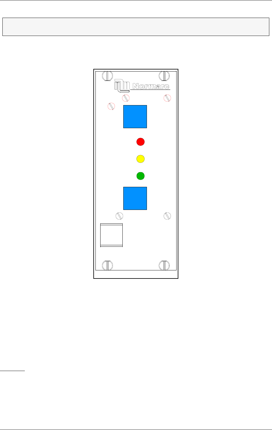
USER MANUAL
9-4
21464-5
NORMARC 7050
MARKER BEACON
Remote Control And Slave Operation ©1999 Navia Aviation AS
• Remote control state transition from NORMAL to ALARM
9.2 Slave Panel Operation
Figure 9-2 Slave Panel
9.2.1 Glossary
INTERLOCK When an ILS is in active interlock mode (the interlock signal is an input to the
remote control), the ILS will turn off all active transmitters and not allow them to
be turned on before the interlock condition is removed. This signal overrides
manual mode of operation.
9.2.2 Push buttons
ON/OFF
Used to:
• Toggle the MB on/off.
Valid when:
• The LOCAL/REMOTE switch must be in REMOTE position, and
• The interlock signal is not active if the MB is configured for interlock.
ΤThe IDENT warning lamp is not in use on Marker Beacon stations. This lamp is for
Localizers and Glide path stations only.
OFF
ON/
WARNING
NORMAL
SILENCE
ALARM
HBK809/1

©1999 Navia Aviation AS 21464-5 Remote Control And Slave Operation
USER MANUALNORMARC 7050
MARKER BEACON
9-5
SILENCE
Used to:
• Turn off the audio alarm on the slave panel (generated by remote control). Also used for
lamp test (all lamps are illuminated when this push button is held down).
Valid when:
•Always.
9.2.3 System Status Indications
ALARM
Used to:
• Indicate that the MB has detected an alarm condition.
Activated by:
• One or more alarms present on the MB, or
• Communication failure with MB.
NORMAL
Used to:
• Indicate that no alarm conditions are detected by the MB.
Activated by:
• No alarms present, and
•ΤCommunication with MB is OK.
WARNING
Used to:
• Indicate that the MB has detected one or more warning conditions.
Activated by:
• Warning condition(s) detected by RMS.

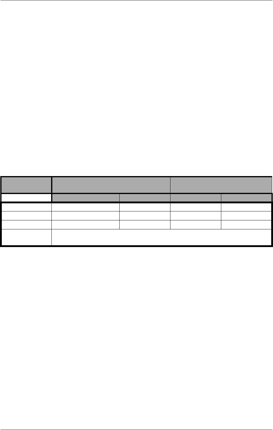
©1999 Navia Aviation AS 21464-5 Operation of RMM
USER MANUALNORMARC 7050
MARKER BEACON
10-1
10 Operation of RMM
This chapter is the user manuasl of the Remote Maintenance Monitoring (RMM) program of
the NM 7050 series Marker Beacon.
10.1 Introduction
The remote monitoring software consists of software running in the MB rack (the RMS) and on
software running on IBM/PC's or compatibles (the RMM). The purpose of the system is to
retrieve status and measurements from the MB rack and to change the MB operation and
parameters. The retrieved data can be displayed and further processed by programs on the
PC. This includes displaying data on screen, saving data and exporting data to other pro-
grams, i.e. for trending analysis.
10.1.1 System Requirements
As mentioned above you need a PC to run the RMM software. The operating system has to
be either Windows 95 (or newer) or Windows NT 4.0 (or newer). The table below shows the
hardware requirements to make the software play well.
Table 10-1 PC hardware requirements
10.1.2 How to use this manual
The RMM is a windows based software, and uses standard windows interface. If you are
familiar with windows you can skip Chapter 10.2.
If you are not the type that reads manuals in bed at night (engineers are usually not), the
chapter 10.4 Getting started will give you a quick guidance into the system.
The chapters 10.4.2 and 10.5.16 are for the System Administrator, normal users may skip
these chapters.
10.2 The desktop area
The purpose of this chapter is to give the inexperienced Windows user some quick instruc-
tions on the environment. If you need more details, please refer to the Windows User's Guide.
Operating Sys-
tem Windows 95 Windows NT
Hardware Minimum Recommended Minimum Recommended
Processor 486DX66 Pentium 75 Pentium75 Pentium 100
Hard disk 200 MB 300 MB
RAM 8 MB 16 MB 20 MB 32 MB
Communication a RS-232 serial port connected to a Hayes compatible 14400 baud, or bet-
ter, modem.
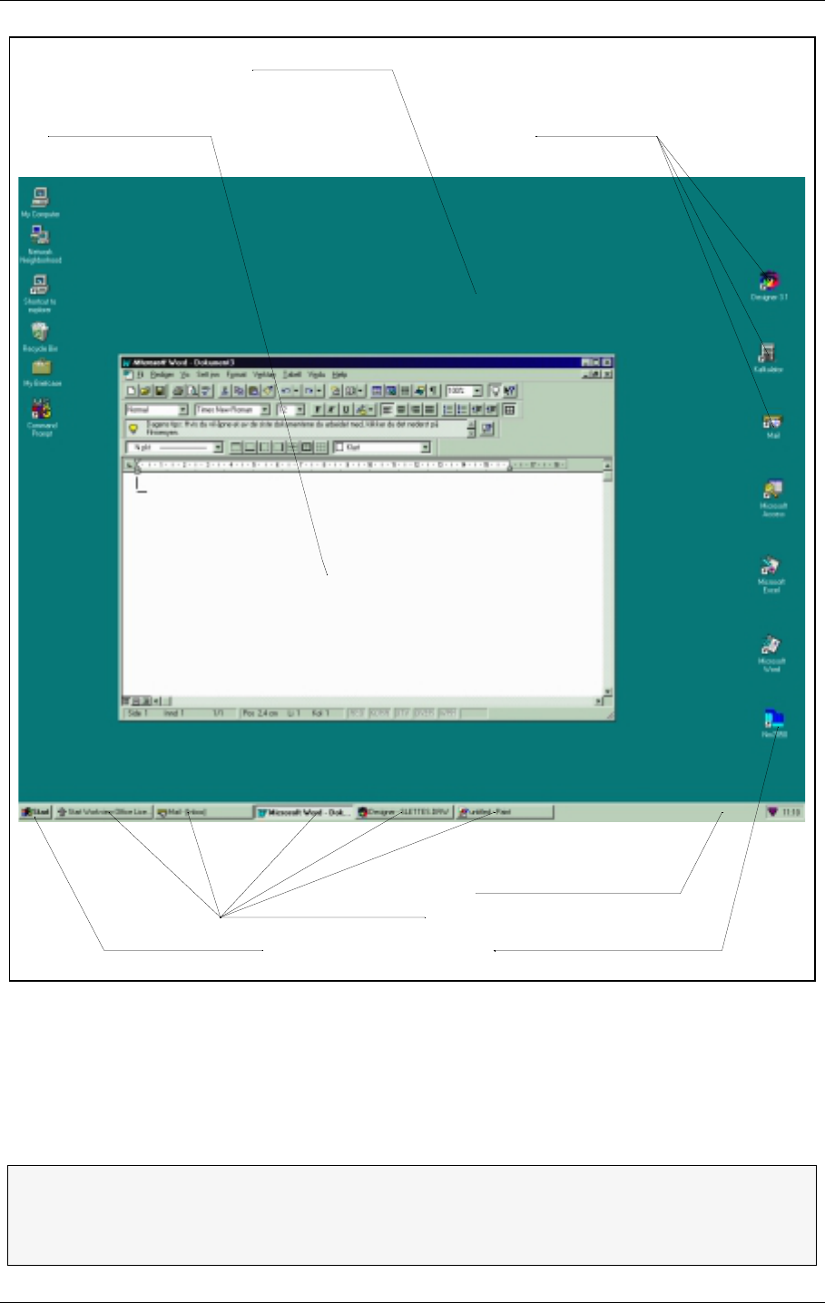
USER MANUAL
10-2
21464-5
NORMARC 7050
MARKER BEACON
Operation of RMM ©1999 Navia Aviation AS
Figure 10-1 A typical Windows 95/NT desktop
The screen background is called a desktop. From this desktop you start and run your pro-
grams and you are quite free to lay out your desktop area as you find practical. All programs
are reachable from the Start menu in the lower left corner. Several programs may run at the
same time and you may hide them by clicking the programs iconize button or bring them to
front by clicking the programs icon in the Windows menu.
ΤTo get quick access to the most frequently used programs you may put a shortcut
icon on your desktop. To start the program, position the mouse pointer over the
icon and double click the left mouse button. See 10.3 on how to create a shortcut
icon.
The active window Shortcut icons
The NM7050 shortcut iconThe Start menu
The Windows menu line
The Desktop
Running processes
H1000/1
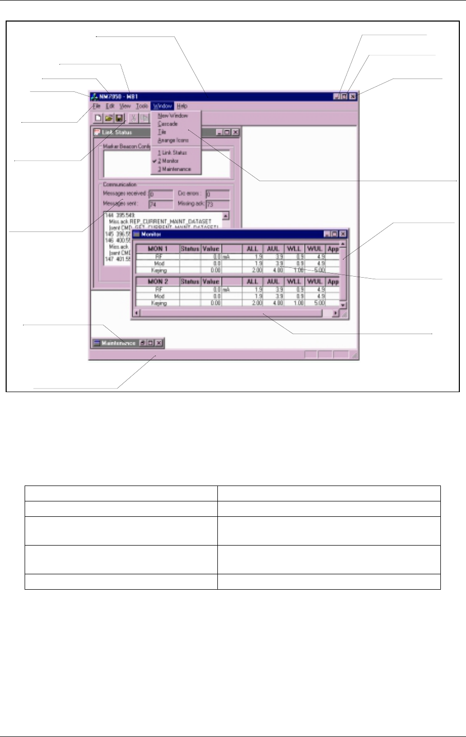
©1999 Navia Aviation AS 21464-5 Operation of RMM
USER MANUALNORMARC 7050
MARKER BEACON
10-3
Figure 10-2 The elements of a typical Windows program environment
Inside a single program you may have several windows open at the same time, too. You open
windows and apply various commands from the menus or by clicking buttons. The com-
mands you apply takes effect in the currently focused window only.
If you want to... Do this...
Open a window Select it from the View menu
Close a window Click on the CLOSE WINDOW button or dou-
ble click on the WINDOW Icon
Maximise a window Click on the MAXIMISE WINDOW button or
Double click on the WINDOW BAR
Minimise a window Click on the ICONIZE WINDOW button
Window bar
Station name
Program name
Menu bar
Tool bar
Background window
Status bar
Horizontal scrollbar
Focused window
Vertical scrollbar
Close button
Maximize window
Iconize window
Drop down menu
Iconized window
Window icon
H1001/1

USER MANUAL
10-4
21464-5
NORMARC 7050
MARKER BEACON
Operation of RMM ©1999 Navia Aviation AS
Table 10-2 Frequently used Windows commands
• A greyed out menu or toolbar item is not a legal option.
• The status bar show various messages from the program
• A focused window (the window you are currently working in) has a dark window bar.
• A background (unfocused) window has a grey window bar.
10.3 Installation
To install the NM7050 RMM program on a hard disk drive:
• Put the first floppy disk in the floppy disk drive or the CD-ROM in the CD-ROM drive
• From the Windows Start Bar, select Start | Run.
• Type a:\SETUP.
• Follow the instructions in the Installation Wizard
You will now have a program group named NAVIA AVIATION in the START|PROGRAMS
menu. In this group the program NM7050 MARKER BEACON appears. Select this to
start the program.
If you want to create a shortcut on your desktop area do this:
• Position your mouse pointer over the program icon in your program group
(you might want to use Windows/NT Explorer for this).
• Click and hold the right mouse button down
• Drag the icon into the desktop area and release the mouse button
• Select the CREATE SHORTCUT(S) HERE option.
• You will now have a shortcut icon with a little arrow on it
10.4 Getting started
You start the program by selecting START|PROGRAMS|NAVIA AVIATION|NM7050 MARKER BEA-
CON in the desktop menu or, if you have created a shortcut, simply by double-clicking the pro-
gram icon on your desktop. The program will now appear as an empty shell.
10.4.1 The normal procedure
You now want to connect to a specific Marker Beacon station. To do this select the FILE|CON-
Move a window Position the cursor over the WINDOW BAR,
hold left mouse button down and move.
Resize a window Position the cursor over one of the edges or
corners. When a double arrow appears,
hold left mouse button down and drag.
Focus on a window Click on the window or
Select it from the Window menu
Move sideways inside a window Click the left or right arrow on the horizontal
scroll bar
Move up or down inside a window Click the up or down arrow on the vertical
scroll bar
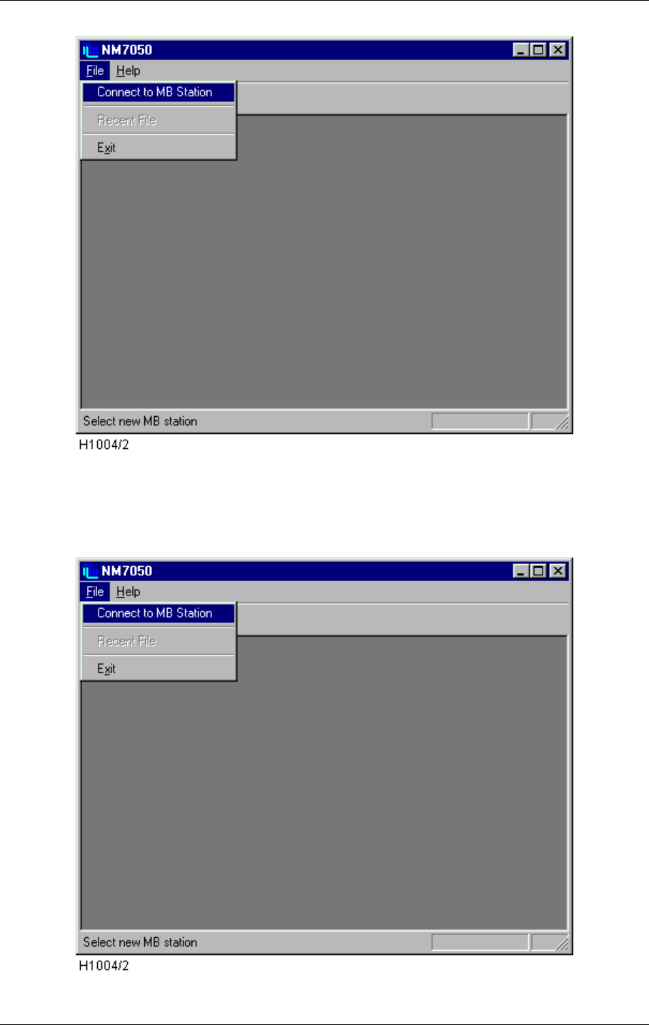
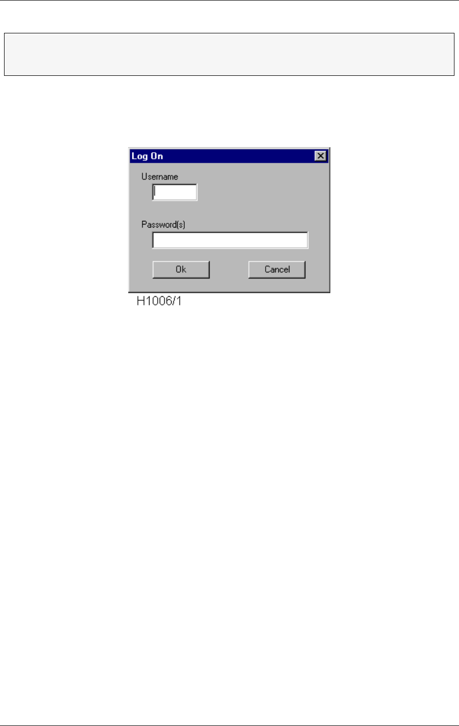
USER MANUAL
10-6
21464-5
NORMARC 7050
MARKER BEACON
Operation of RMM ©1999 Navia Aviation AS
Figure 10-4 Station List
To select a station, click on the line and it will be highlighted. Now click on the CONNECT but-
ton and the Log On window will appear. Alternatively you can double-click on a station.
Figure 10-5 Logging on
Due to the strict security demands for the landing systems, the system is protected from
unwanted access with USERNAMES and three levels of PASSWORDS. Now enter your user
name and password(s) (separated with space) according to your access level. If you don't
have a user name, please contact the System Administrator. For explanations on access
levels, see chapter 10.5.3 (Logging in and out and access levels).
The desktop will now show the Link Status window. This window shows the station's config-
uration and the communication status. But you are probably more interested in the station's
overall status, the value of the measured parameters and maybe the system settings. To do
this you have to open one or more of the Monitor, Maintenance and TX settings windows
from the VIEW menu.
The NM7050 program can only connect to one station at a time. To connect to
several stations you have to start the program once for each station. But be
aware that you need one communication (COM-) port on your PC for each station.
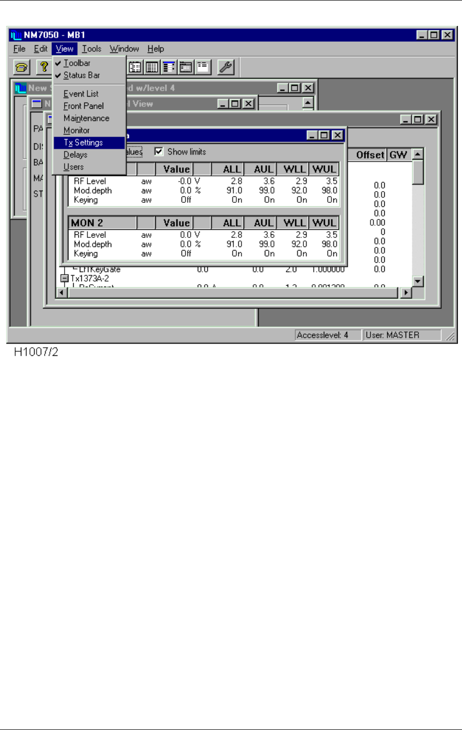
©1999 Navia Aviation AS 21464-5 Operation of RMM
USER MANUALNORMARC 7050
MARKER BEACON
10-7
Figure 10-6 Opening more windows
The windows will now appear on top of each other. Use a couple of minutes to organise your
desktop by moving and resizing the windows. The program will remember your current set-
tings the next time the program starts. The windows that were shown when you last discon-
nected from the station will be reopened at next log on.
The final result of your desktop organisation may look something like this:
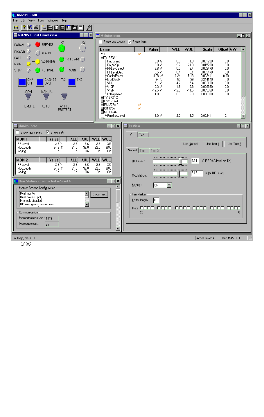
USER MANUAL
10-8
21464-5
NORMARC 7050
MARKER BEACON
Operation of RMM ©1999 Navia Aviation AS
Figure 10-7 An organised desktop
You are now up and running. For further explanations on windows and commands see para-
graph 10.5.
Logging off is done by selecting the DISCONNECT button in the same window, or by closing the
Link Status window.
10.4.2 The very first time
The very first time you log on to a Marker Beacon Station there are some differences from the
normal procedure:
• You have no physical connection to the station
• The Station List is empty
• There is only one valid USERNAME/PASSWORD combination
10.4.2.1 Establishing the physical connection
Use the delivered PC-cable with 9 pins D-SUB contact in both ends. Plug one end in either
the Local port on the Marker Beacon front panel, or in the Remote Port on the motherboard
inside the cabinet. The other end of the cable must be put in one of your PC's COM-ports (i.e.
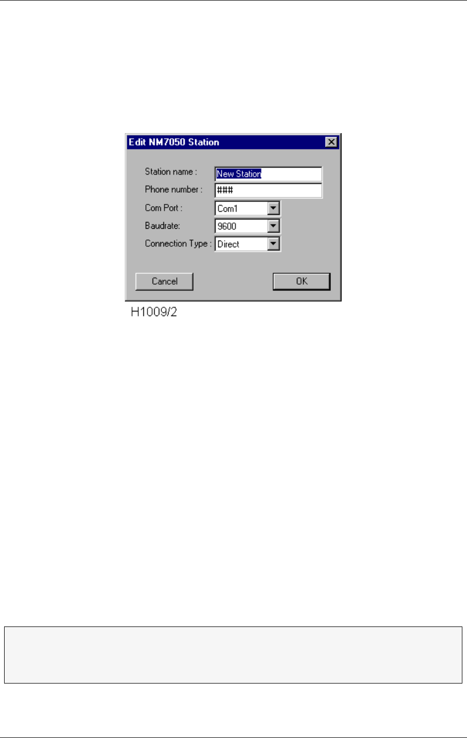
©1999 Navia Aviation AS 21464-5 Operation of RMM
USER MANUALNORMARC 7050
MARKER BEACON
10-9
COM1). The Write Protect switch must be in OFF position (upwards) for access level 3 or
higher.
10.4.2.2 Editing the station list
After applying FILE|CONNECT TO MB STATION from the menu, an empty Station List window
appears on the screen. Now click the NEW button, and the Edit Station window will pop up:
Figure 10-8 Creating a new station
•Station Name: You may call the station AUNT MARY or SMOKED SALMON WITH SCRAMBLED
EGGS, but it is probably more convenient to call it something like FBRWY09MM.
•Phone number: You don't need to enter this now as you are directly connected to the
equipment. For further details see chapter 10.5.4 Station list.
•Com Port: Here you enter the communication port you put your PC cable in, i.e. COM1.
•BAUDRATE: Select among the baudrate options available. Normally 9600 works well.
•Connection Type: Enter DIRECT as you use no modem.
Click OK and you will return to the Station List. Now highlight the station by clicking the left
mouse button over it, and then click CONNECT.
10.4.2.3 Logging on
For establishing the connection to the station you have to enter a USERNAME and three PASS-
WORDS. There is only one key to the lock, the so called Master account. Enter :
USERNAME: Master
PASSWORDS: Master1 Master2 Master3
NOTE! The passwords are space separated.
For changing the PASSWORDS see chapter 10.5.16 Administration.
ΤThe Master account has unrestricted access to the system. In order to keep your
system safe, change the passwords immediately and REMEMBER them. If you
have to write the passwords down, keep them in a safe place far away from the
station. This applies for the Menu Password as well.
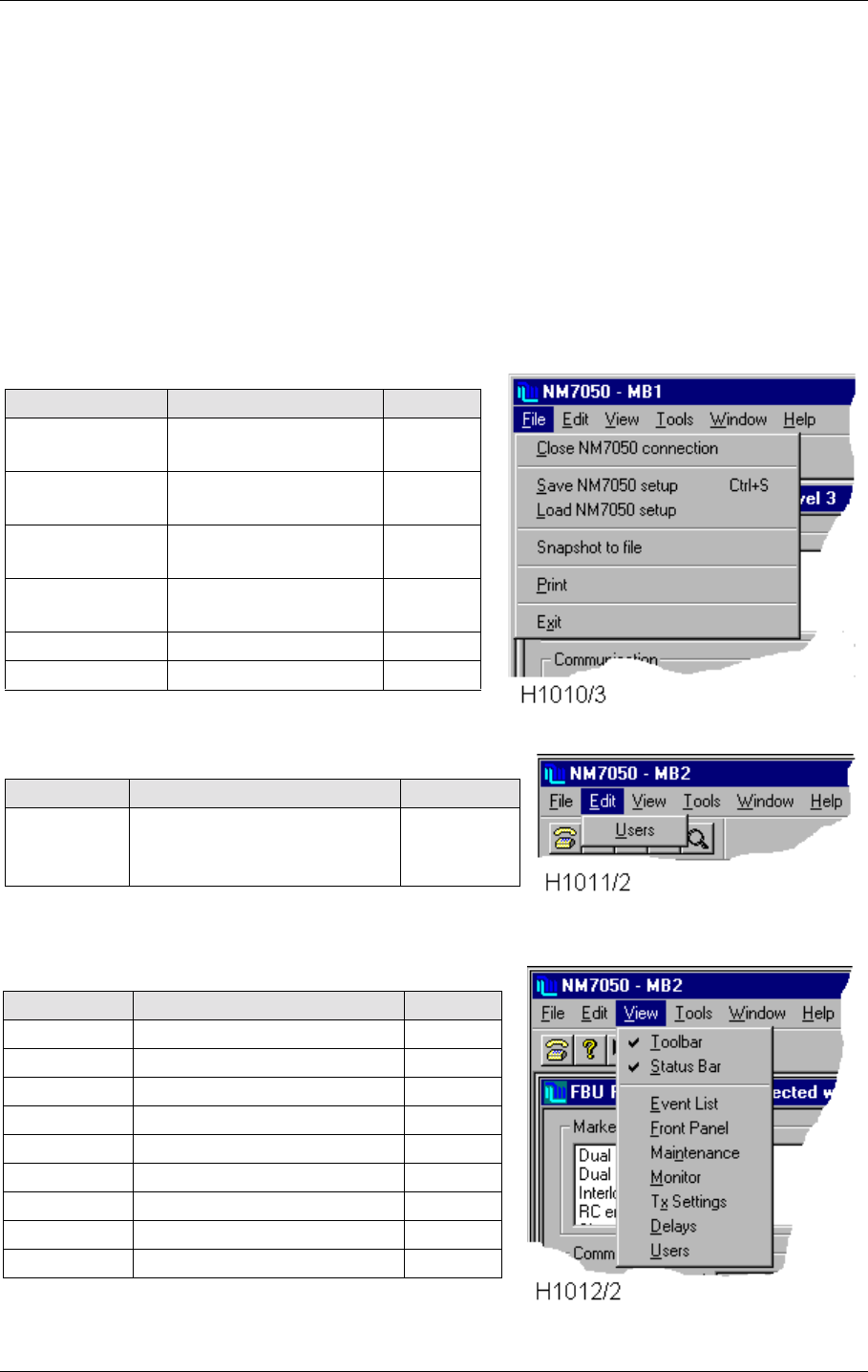
USER MANUAL
10-10
21464-5
NORMARC 7050
MARKER BEACON
Operation of RMM ©1999 Navia Aviation AS
10.5 Users guide
In this chapter we will go through the windows, menus, tools and buttons in greater detail.
10.5.1 The menus
There are six menus:
•File - Log on, exit, print, etc.
•Edit - Edit user privileges
•View - Opening windows, toolbar and status bar
•Tools - Options, logging and secondary parameters
•Window - Arranging the opened windows
•Help - Opening help, program information
Table 10-3 The FILE menu
Table 10-4 The EDIT menu
Table 10-5 The VIEW menu
Entry Function Shortcut
Close MB con-
nection Close this MB session Alt-F-C
Save NM7050
setup Save NM7050 limits/
delays to file Alt-F-S
Load NM7050
setup Set NM7050 limits/
delays from file Alt-F-L
Snapshot to file Snapshot of mon/
maint data to textfile
Print Print a report Alt-F-P
Exit Exit the program Alt-F-X
Entry Function Shortcut
Users Create, delete or change
users. Change menu pass-
word.
Alt-E-U
Entry Function Shortcut
Toolbar Show or hide toolbar Alt-V-T
Status Bar Show or hide status bar Alt-V-S
Event List Open event list Alt-V-E
Front Panel Open front panel Alt-V-F
Maintenance Open maintenance window Alt-V-N
Monitor Open monitor window Alt-V-M
TX settings Open TX settings window Alt-V-X
Delays Open delays window Alt-V-D
User List Open the list of users Alt-V-U
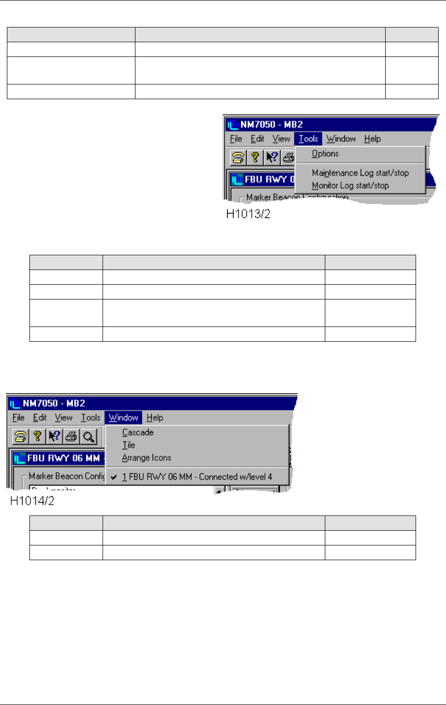
©1999 Navia Aviation AS 21464-5 Operation of RMM
USER MANUALNORMARC 7050
MARKER BEACON
10-11
Table 10-6 The TOOLS menu
Table 10-7 The WINDOW menu
Table 10-8 The HELP menu
Entry Function Shortcut
Options Secondary settings Alt-T-O
Maintenance Log start/
stop Start or stop logging of maintenance parameters to
file. Alt-T-N
Monitor Log start/stop Start or stop logging of monitor parameters to file. Alt-T-M
Entry Function Shortcut
Cascade Put opened windows on top of each other Alt-W-C
Tile Arrange opened windows all visible Alt-W-T
Arrange Icons Arrange iconized windows in the lower part of
the program window Alt-W-A
Window list Quick selection of opened windows Alt-W-<number>
Entry Function Shortcut
Help Topics Open help window Alt-H-H
About Information about program Alt-H-A
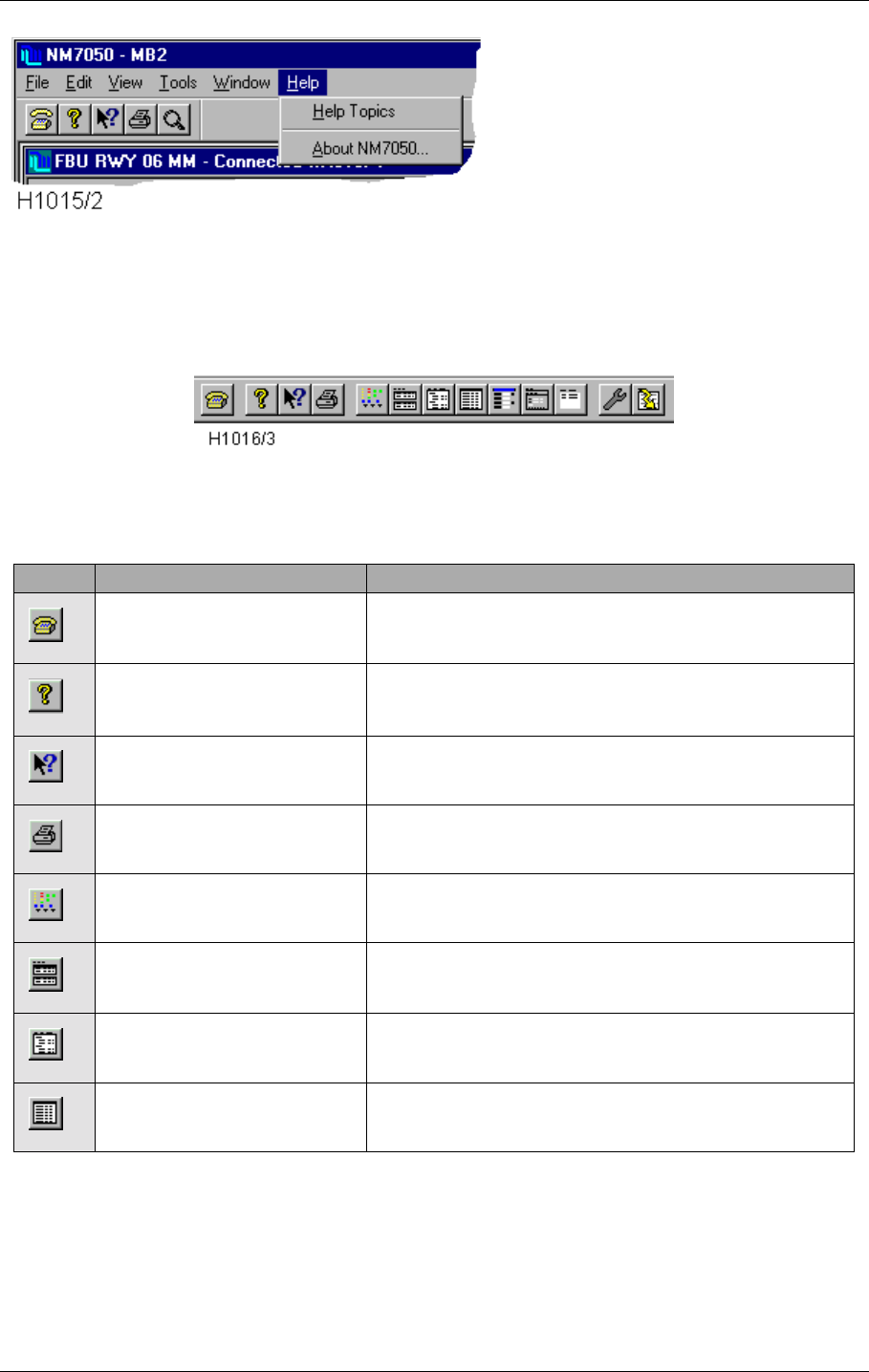
USER MANUAL
10-12
21464-5
NORMARC 7050
MARKER BEACON
Operation of RMM ©1999 Navia Aviation AS
10.5.2 The toolbar
Figure 10-9 The toolbar
The toolbar is a selection of shortcuts to menu commands. To activate the command simply
click the button.
Entry Menu command Function
File | Connect to MB station Connect to a NM7050 MB station
Help | About NM 7050 Shows the software versions in use etc.
Help on command Click the command you want help on.
File - Print Print standard maintenance report.
View | Front panel Open the front panel view
View | Monitor Open the monitor data view
View | Maintenance Open the maintenance data view
View | Events Open the events view
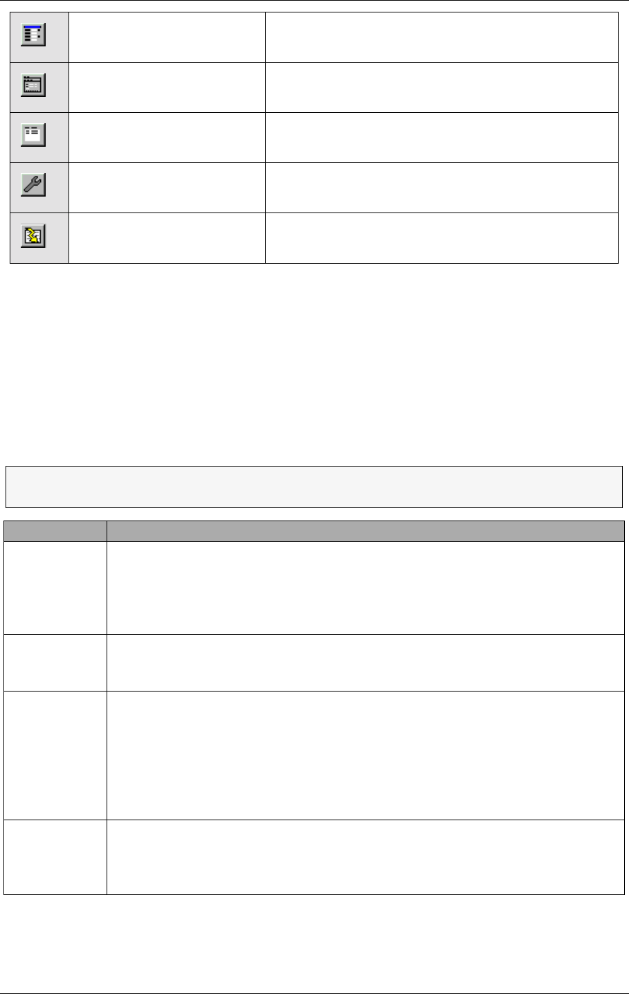
©1999 Navia Aviation AS 21464-5 Operation of RMM
USER MANUALNORMARC 7050
MARKER BEACON
10-13
Table 10-9 The toolbar entries
10.5.3 Logging in and out and access levels
In order to keep your landing system safe and reliable, the opening of the RMM communica-
tion is secured with a USERNAME and one to three PASSWORDS. The number of passwords cor-
responds to the ACCESS LEVEL, which again give different permissions to the system as The
access levels shows.
Table 10-10 The access levels
After you have selected the MB station the Log On dialogue appears. Enter your USERNAME,
use the tabulator on the keyboard or the mouse pointer to move to the PASSWORD field and
View | Delays Open the delays view
View | TX settings Open the TX setting view
View | Users Open the user list view
Tools | Options Open the options dialogue
File | Snapshot to file Saves current monitor and maintenance data in tex-
tfile
ΤThe system administrator will supply you with a user name and passwords
according to your access level.
Access level Permissions
1• Readout of all the monitor values, warning and alarm limits.
• Readout of all the maintenance values and warning limits.
• Readout of all the delays.
• Readout of all the TX1 and TX2 configurations.
• Readout of users (only id's and last logout time)
2• Level 1 +
• Turning on and off transmitters (same as using the front panel buttons)
• TX1 and TX2 : Using pre-programmed test settings.
3• Level 2 +
• Settings of all the monitor warning and alarm limits.
• Settings of all the maintenance warning limits.
• Settings of all the delays.
• Settings of all the TX1 and TX2 configurations.
• Modulation tone settings to NORMAL, CONTINUOUS or OFF on TX1/TX2.
• Start initialisation of modem.
Master • Level 3 +
• User administration
• Communications set-up
• Setting system date and time
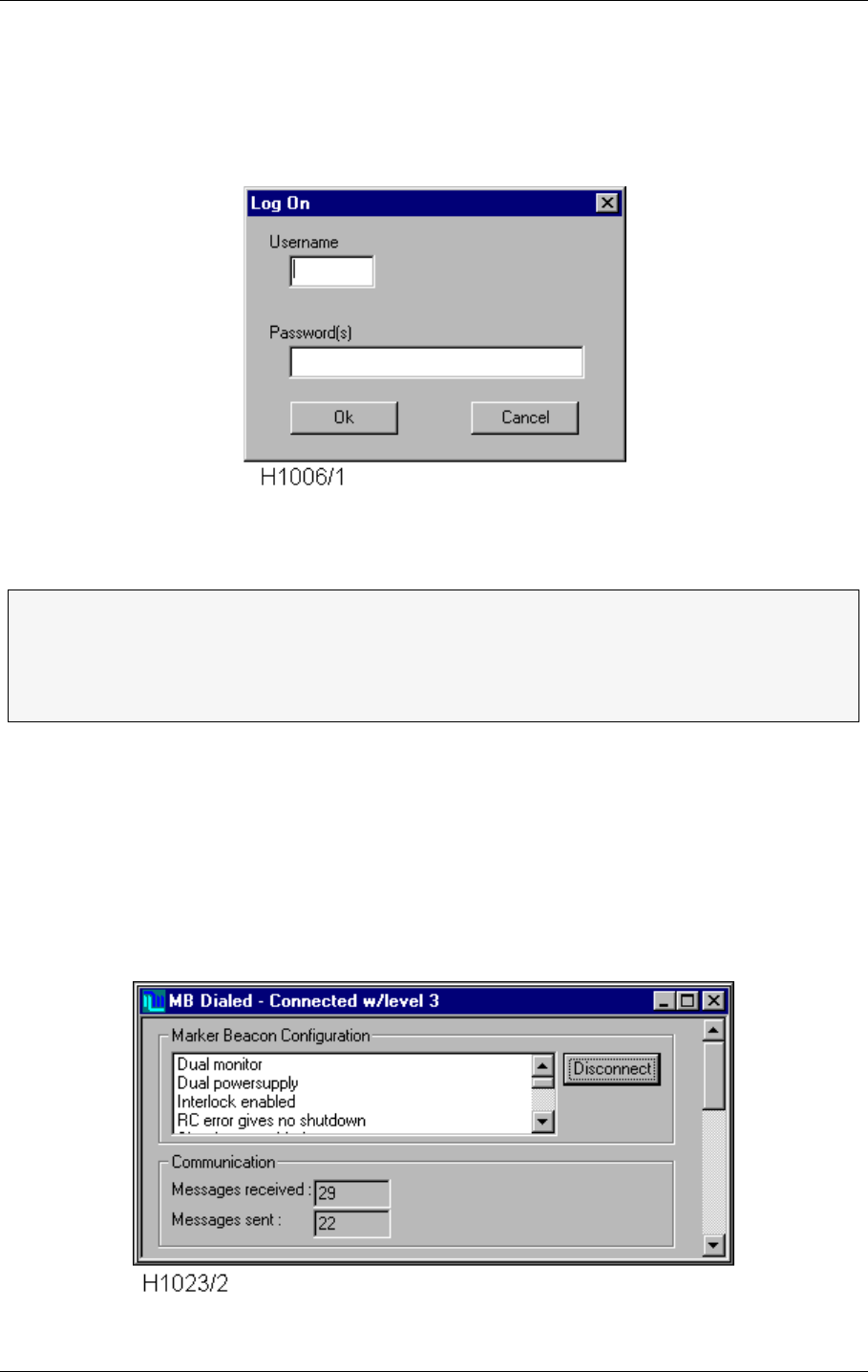
USER MANUAL
10-14
21464-5
NORMARC 7050
MARKER BEACON
Operation of RMM ©1999 Navia Aviation AS
enter your password(s). To finish the operation, click the OK button or press ENTER on the
keyboard.
• A user name may be written in either upper or lower case letters
• A password is not case sensitive.
• Multiple passwords are separated with a single space.
Figure 10-10 The Log On dialogue
The Link status window shows the configuration of the NM7050, that is:
• Inner, middle, outer marker or fan marker (set on each of the transmitters)
• One or two power supplies (set on configuration platform inside the cabinet)
• One or two monitors (set on configuration platform inside the cabinet)
• Shutdown at standby failure (set on configuration platform inside the cabinet)
• Shutdown at remote control failure (set on configuration platform inside the cabinet)
• In addition the communication status is shown.
Figure 10-11 The Link Status window
ΤYou may restrict your system from remote access level 2 or 3 connections on the
remote RS232 comm. port. The access level 2 or 3 user then have to connect
directly to the Local port at the Marker Beacon site. To achieve this, the hardware
straps 6 (access level 2 inhibit) or 7 (access level 3 inhibit) on the configuration
platform must be removed inside the Marker Beacon cabinet.
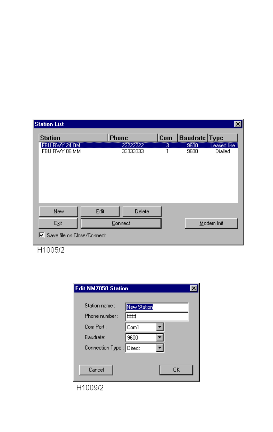
©1999 Navia Aviation AS 21464-5 Operation of RMM
USER MANUALNORMARC 7050
MARKER BEACON
10-15
Logging off is done by clicking the DISCONNECT button or by simply closing the Link Status
window.
10.5.4 Station list
The Station List is a list of the currently available Marker Beacon stations. You may connect
to, add, edit or remove entries on the list. This is also the place to set up the modem connec-
tions.
You may have different types of connections to the same station, i.e. one direct line, one
leased line and one dialled line connection. This can be particularly useful on portable PC's
that are used both on site, in the control room and more distant places.
Figure 10-12 The Station List view
Figure 10-13 The Edit Station view
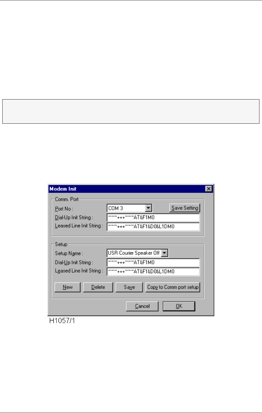
USER MANUAL
10-16
21464-5
NORMARC 7050
MARKER BEACON
Operation of RMM ©1999 Navia Aviation AS
The STATION NAME may be chosen freely. The maximum number of characters is unlimited
for all practical purposes. Be aware that this name will also be the name of the home directory
for this station, where for example the log files will be put as default. We recommend mean-
ingful names like MIDDLE MARKER 01, OUTER MARKER 19 LEFT to tell the marker type and run-
way end. You may also include the site name if you handle NM7050s on more than one
airport.
The PHONE NUMBER is only necessary when using modems on the public telephone net (CON-
NECTION TYPE = DIALLED). Simply enter the telephone number in the same way that you would
dial on your phone.
10.5.5 Modem set-up
To change set up for connected modems, select the MODEM INIT button in the Station List
View. You will now enter the modem set-up dialogue.
Figure 10-14 The Modem Init window
The Comm. Port part of the dialogue shows the set-ups for the modems connected. Note that
these set-ups are based on what kind of modems that are connected to each of the COM
ports connected to the PC. There are set-ups for both normal DIAL-UP INIT STRING and LEASED
LINE INIT STRING. Theses strings are sent to the modems at the start of a station connection,
but only if DIAL-UP or LEASED LINE is selected in the Station List View. When changing the
settings, remember to select the SAVE SETTING button before exiting the dialogue (pressing
the OK button). These settings are saved for the next time you start up the program.
ΤIf your modem connection have to go through a local telephone switchboard, you
have to enter the code to get the public dial tone, to commas to make a pause and
finally the phone number. Ex.: 0,,11223344
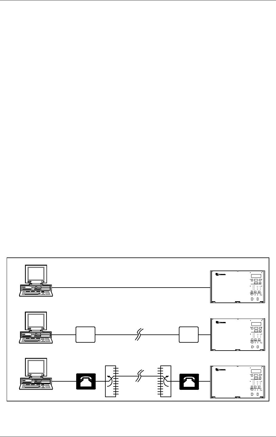
©1999 Navia Aviation AS 21464-5 Operation of RMM
USER MANUALNORMARC 7050
MARKER BEACON
10-17
The Set-up part of the dialogue is just a collection of fixed set-ups that can be selected (by
using the SETUP NAME combo box), and then copied to the set-up for the selected COM port
(by selecting the COPY TO COMM PORT SETUP button). The set-ups can be edited and saved
much in the same way as the stations in the Station List View.
10.5.6 Setting up connections
The Com Port is a physical plug on your PC that transfers serial data communication. They
are normally tagged COM1, COM2,.... on the rear of your PC. A standard PC configuration
has two COM-ports where the mouse might occupy one of them. Use a free COM port to con-
nect your modem or NM7050 directly and select the same port from the list. If you have a
modem installed the list will say for instance MODEM ON COM2.
There are three CONNECTION TYPES:
• Direct Line
• Leased Line
• Dialled Line
DIRECT LINE is typically a serial link cable with a nine pins D-SUB contact in each end. You
may use either the Local or the Remote port on NM7050 and one of the COM ports on your
PC. The direct line is limited to approximately 15 m cable length.
LEASED LINE is a dedicated telephone line where you are the only user. There will be no need
of a telephone number, but you need a leased-line type modem in each end to be able to drive
the line. There is no length restrictions on a leased line if the telephone line standards are fol-
lowed.
DIALLED LINE is a normal public telephone line where the signal passes a number of telephone
switches on its travel. You need a dial up modem to dial the number and drive the telephone
line. As with normal telephones, you may phone all over the world.
Figure 10-15 The connection types
MARKER BEACON SYSTEM
Dial up modem
Telephone
switch Telephone
switch
Leased line modem Leased line modem
Leased line
(>15m)
Dialled line
(>15m)
Direct line (<15m)
H1024-1
MARKER BEACON SY STEM
MARKER BEACON SYSTEM

USER MANUAL
10-18
21464-5
NORMARC 7050
MARKER BEACON
Operation of RMM ©1999 Navia Aviation AS
10.5.6.1 Setting up a Dial-up connection with an US Robotics Courier V34 modem
This section describes how to set up communication for dialled operation using the US
Robotics Courier V34 modem on the REMOTE port on the NM7050. See also the description
of connection types .
10.5.6.1.1 What to do on the NM 7050 side:
1. Connect a PC directly to the Local RS232 port on the front of the NM7050 and log on as
MASTER with three passwords.
2. After connection has been established, go to the Tool|Options menu and select the
NM7050 Communications tab.
3. Connect the modem to the remote RS232 connector inside the NM7050 cabinet and make
sure that the modem power is turned off.
4. Set the DIP switches at the bottom of the modem in the following positions :
ON OFF ON OFF OFF OFF OFF ON OFF ON
5. Turn the power on and wait a few seconds before turning the power off again.
6. Turn DIP switch 10 to OFF and turn on the modem power again.
7. Uncheck the Use modem default init checkbox.
8. Write ~~~+++~~~ in the User modem init string field.
9. Select the Apply button that popped up above the User modem init string field.
10.Select the Init modem button.
11.After approximately 10 seconds after the Init modem button was pressed the Last modem
result field shall read an OK message.
12.Write AT&F1&L0S0=1&W in the User modem init string field and repeat 8-11.
13.The modem shall now turn on the AA led (if not already on). The AA led indicates that this
modem is ready to answer calls from other modems.
14.Log off the local RS232 port.
10.5.6.1.2What to do on the RMM side:
1. Connect the RMM PC to the other modem (the modem that shall be used to call up the
modem connected to NM7050).
2. Turn the power on the modem off.
3. Set the DIP switches at the bottom of the modem in the following positions :
OFF OFF ON OFF ON OFF OFF ON OFF ON
4. Turn the power on and wait a few seconds before turning the power off again.
5. Turn DIP switch 10 to OFF and turn on the modem power again.
6. Enter the station list dialog (menu File | Connect to MB station).
7. Edit or create a new station to match the comm. port the modem is connected to, and with
the same baudrate as set for the remote port on the NM7050 (usually 9600).
8. Set the Connection Type to Dialed.
9. Select the modem init button for entering the Modem Init dialog .
10.Fill the Dial-Up Init String field with the string ~~~+++~~~AT&F1&L0&W .
11.If you have changed the setting, select the Save Setting button to actually store the new
dialed setup for the comm. port.
ΤIf you use Leased Line the two modems have to be identical, or else they might
not communicate well.
ΤA leased line modem may be a standard commercial modem used in leased line
mode.

©1999 Navia Aviation AS 21464-5 Operation of RMM
USER MANUALNORMARC 7050
MARKER BEACON
10-19
12.Select OK to get back to the station list.
13.If necessary modify the telephone number to the number that the NM7050 modem is con-
nected to.
14.Select the dialed station in the list and select the Connect button.
15.The modem shall now take off the hook (OH Led illuminated) and start to call the phone
number for the modem connected to NM7050.
16.After some time (up to 30-40 seconds), the two modems should connect, if everything is
OK. This will be indicated by an illuminated CD Led on both modems.
After this set-up, all you have to do to reconnect another time is to select the correct station in
the station list and select the Connect button.
10.5.6.2 Setting up a Dial-Up connection with a Westermo modem
This section describes how to set up communication for dialled operation using the Westermo
TD-32AC / TD-32DC modem on the REMOTE port on the NM7050. See also the description
of connection types .
10.5.6.2.1What to do on the NM7050 side
1. Connect a PC directly to the Local RS232 port on the front of the NM7050 and log on as
MASTER with three passwords.
2. After connection has been established, go to the Tool|Options menu and select the
NM7050 Communications tab.
3. Connect the modem to the remote RS232 connector inside the NM7050 cabinet and make
sure that the modem power is turned off.
4. Set the DIP switches inside the modem in the following positions :
SW1 : All OFF
SW2 : 1 and 4 ON, all other OFF
SW3 : 1 ON, all other OFF
SW4 : 2, 3, 5 and 6 ON, all other OFF for baudrate 9600, 3, 5 and 6 ON, all other OFF for
badurate 4800, 5 and 6 ON, all other OFF for badurate 2400
SW5 : 1, 2, 3 and 4 ON, all other OFF
Note that SW4 must be set equal on both modems!
5. Turn the power on and wait a few seconds.
6. Uncheck the Use modem default init checkbox.
7. Write ATE0&C1&D2&W in the User modem init string field.
8. Select the Apply button that popped up above the User modem init string field.
9. Select the Init modem button.
10.After approximately 10 seconds after the Init modem button was pressed the Last modem
result field shall read an OK message.
11.The modem shall now enter the Auto Answer mode, though the ANS led will not immedi-
ately be illuminated. The ANS led will blink when a ring signal is detected on the line. After
this the ANS led will be on continuously when waiting for incoming calls.
12.Log off the local RS232 port.
10.5.6.2.2What to do on the RMM side:
1. Connect the RMM PC to the other modem (the modem that shall be used to call up the
modem connected to NM7050).
2. Turn the power on the modem off.
3. Set the DIP switches inside the modem in the following positions :
SW1 : 1 ON, all other OFF
SW2 : 1 ON, all other OFF

USER MANUAL
10-20
21464-5
NORMARC 7050
MARKER BEACON
Operation of RMM ©1999 Navia Aviation AS
SW3 : 1 ON, all other OFF
SW4: 2, 3, 5 and 6 ON, all other OFF for baudrate 9600, 3, 5 and 6 ON, all other OFF for
badurate 4800, 5 and 6 ON, all other OFF for badurate 2400
SW5 : 1, 2, 3 and 4 ON, all other OFF
Note that SW4 must be set equal on both modems!
4. Turn the power on and wait a few seconds before turning the power off again.
5. Enter the station list dialog (menu File | Connect to MB station).
6. Edit or create a new station to match the comm. port the modem is connected to, and with
the same baudrate as set for the remote port on the NM7050 (usually 9600).
7. Set the Connection Type to Dialed.
8. Select the modem init button for entering the Modem Init dialog .
9. Fill the Dial-Up Init String field with the string ATX3&C1&D2\N5&W .
10.If you have changed the setting, select the Save Setting button to actually store the new
dialed setup for the comm. port.
11.Select OK to get back to the station list.
12.If necessary modify the telephone number to the number that the NM7050 modem is con-
nected to.
13.Select the dialed station in the list and select the Connect button.
14.The modem shall now start to call the phone number for the modem connected to
NM7050.
15.After some time (up to 30-40 seconds), the two modems should connect, if everything is
OK. This will be indicated by illuminated LINE Led on both modems.
After this setup, all you have to do to reconnect another time is to select the correct station in
the station list and select the Connect button.
10.5.6.3 Setting up a leased-line connection with a US Robotics Courier V34 modem
This section describes how to set up communication for leased line operation using the US
Robotics Courier V34 modem on the Remote port on the NM7050. See also the description of
connection types .
10.5.6.3.1What to do on the NM 7050 side:
1. Connect a PC directly to the Local RS232 port on the front of the NM7050 and log on as
MASTER with three passwords.
2. After connection has been established, go to the Tool|Options menu and select the
NM7050 Communications tab.
3. Connect the modem to the remote RS232 connector inside the NM7050 cabinet and make
sure that the modem power is turned off.
4. Set the DIP switches at the bottom of the modem in the following positions :
ON OFF ON OFF OFF OFF OFF ON OFF ON
5. Turn the power on and wait a few seconds before turning the power off again.
6. Turn DIP switch 10 to OFF and turn on the modem power again.
7. Uncheck the Use modem default init checkbox.
8. Write ~~~+++~~~ in the User modem init string field.
9. Select the Apply button that popped up above the User modem init string field.
10.Select the Init modem button.
11.After approximately 10 seconds after the Init modem button was pressed the Last modem
result field shall read an OK message.
12.Write AT&F1&L1S0=1&W in the User modem init string field and repeat 8-11.
13.Turn the power on the modem off, wait a few seconds, and turn it on again.

©1999 Navia Aviation AS 21464-5 Operation of RMM
USER MANUALNORMARC 7050
MARKER BEACON
10-21
14.The modem shall now turn on the AA led (if not already on) and the OH led. The OH led
may be turned off for short periods of time when not connected, but it shall be turned on
again within approximately 30 seconds.
15.Log off the local RS232 port.
10.5.6.3.2What to do on the RMM side:
1. Connect the RMM PC to the other modem (the modem who's line is connected to the
modem you just initialized on the NM7050 side).
2. Turn the power on the modem off.
3. Set the DIP switches at the bottom of the modem in the following positions :
OFF OFF ON OFF ON OFF OFF ON OFF ON
4. Turn the power on and wait a few seconds before turning the power off again.
5. Turn DIP switch 10 to OFF and turn on the modem power again.
6. Enter the station list dialog (menu File | Connect to MB station).
7. Edit or create a new station to match the comm. port the modem is connected to, and with
the same baudrate as set for the remote port on the NM7050 (usually 9600).
8. Set the Connection Type to Leased Line.
9. Select the modem init button for entering the Modem Init dialog .
10.Fill the Leased Line Init String field with the string ~~~+++~~~AT&F1&L1D&W.
11.If you have changed the setting, select the Save Setting button to actually store the new
leased line setup for the comm. port.
12.Select OK to get back to the station list.
13.Select the leased line station in the list and select the Connect button.
14.The modem shall now take off the hook (OH Led illuminated) and the two modems shall
now start to try to connect to each other.
15.After some time (up to 30-40 seconds), the two modem should connect. This will be indi-
cated by and illuminated CD Led on both modems.
10.5.6.3.3Troubleshooting the leased line connetion
1. If the OH lamp on one or both of the two modems don't illuminate at all within a time period
of longer than 30 seconds, try to turn the modem power off and on again for that modem.
2. Check that the line cord between the two modems are not broken or short-circuited.
3. Check that the AA lamp on the modem connected to the NM7050 is illuminated.
10.5.6.4 Setting up a leased-line connection with a Westermo modem
This section describes how to set up communication for leased line operation using the West-
ermo TD-32AC / TD-32DC modem on the Remote port on the NM7050. See also the descrip-
tion of connection types .
10.5.6.4.1What to do on the NM7050 side:
1. Connect a PC directly to the Local RS232 port on the front of the NM7050 and log on as
MASTER with three passwords.
2. After connection has been established, go to the Tool|Options menu and select the
NM7050 Communications tab.
3. Connect the modem to the remote RS232 connector inside the NM7050 cabinet and make
sure that the modem power is turned off.
4. Set the DIP switches inside the modem in the following positions :
SW1: 2 and 4 ON, all other OFF
SW2: 1 and 4 ON, all other OFF
SW3: 1 ON, all other OFF

USER MANUAL
10-22
21464-5
NORMARC 7050
MARKER BEACON
Operation of RMM ©1999 Navia Aviation AS
SW4: 2, 3, 5 and 6 ON, all other OFF for baudrate 9600, 3, 5 and 6 ON, all other OFF for
badurate 4800, 5 and 6 ON, all other OFF for badurate 2400
SW5: 4 ON, all other OFF
Note that SW4 must be set equal on both modems!
5. Turn the power on and wait a few seconds.
6. Check the Use modem default init checkbox.
7. Select the Init modem button. Ignore the Last modem result message.
8. Log off the local RS232 port.
10.5.6.4.2What to do on the RMM side:
1. Connect the RMM PC to the other modem (the modem who's line is connected to the
modem you just initialized on the NM7050 side).
2. Turn the power on the modem off.
3. Set the DIP switches inside the modem in the following positions :
SW1 : 1 ON, all other OFF
SW2 : 1 ON, all other OFF
SW3 : 1 ON, all other OFF
SW4 : 2, 3, 5 and 6 ON, all other OFF for baudrate 9600, 3, 5 and 6 ON, all other OFF for
badurate 4800, 5 and 6 ON, all other OFF for badurate 2400
SW5 : 1, 2, 3 and 4 ON, all other OFF
Note that SW4 must be set equal on both modems!
4. Turn the power on and wait a few seconds.
5. Enter the station list dialog (menu File | Connect to MB station).
6. Edit or create a new station to match the comm. port the modem is connected to, and with
the same baudrate as set for the remote port on the NM7050 (usually 9600).
7. Set the Connection Type to Leased Line.
8. Select the modem init button for entering the Modem Init dialog .
9. Fill the Leased Line Init String field with the string AT\N5&D0&C1&L1&WD . If you experi-
ence trouble with connecting using this init string, there might have been a restart of the
NM7050 since last connection. In this case you might have to use the following init string:
ATH0\N5&D0&C1&L1&WD .
10.If you have changed the setting, select the Save Setting button to actually store the new
leased line setup for the comm. port.
11.Select OK to get back to the station list.
12.Select the leased line station in the list and select the Connect button.
13.The modem shall now start connect with the other modems shall now start to try to connect
to each other.
14.After some time (up to 30-40 seconds), the two modem should connect. This will be indi-
cated by illuminated LINE Leds on both modems.
10.5.7 Front panel
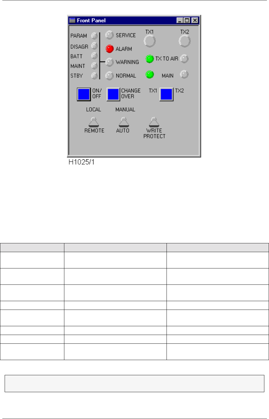
©1999 Navia Aviation AS 21464-5 Operation of RMM
USER MANUALNORMARC 7050
MARKER BEACON
10-23
Figure 10-16 The front panel
The Front Panel has the mostly the same functionality as the physical front panel. For details
on the front panel functionality, see chapter 8.
Front panel switch operation is restricted to certain access levels as shown in Tabelle 10-12.
The LOCAL/REMOTE and WRITE PROTECT switches are only status indicators, while the MAN-
UAL/AUTO switch is controllable too.
Table 10-11 Front panel buttons
Button Function Valid in access level
TX1 Turn on transmitter 1 in manual
mode 2/3
TX2 Turn on transmitter 2 in manual
mode 2/3
MAIN SELECT (TX1 -
TX2) Select main transmitter (the other
one is standby) 2/3
ON/OFF Toggle main transmitter on/off 2/3
CHANGE OVER Change active transmitter
(reflected in TX TO AIR) 2/3
LOCAL/REMOTE Show local or remote mode Not controllable in RMM
MANUAL/AUTO Set manual or automatic mode 2/3
WRITE PROTECT Show if permanent changes of set-
tings are enabled Not controllable in RMM
Since the MANUAL/AUTO switch on the RMM front panel is controllable it will NOT
necessarily reflect the position of the physical MANUAL/AUTO switch.
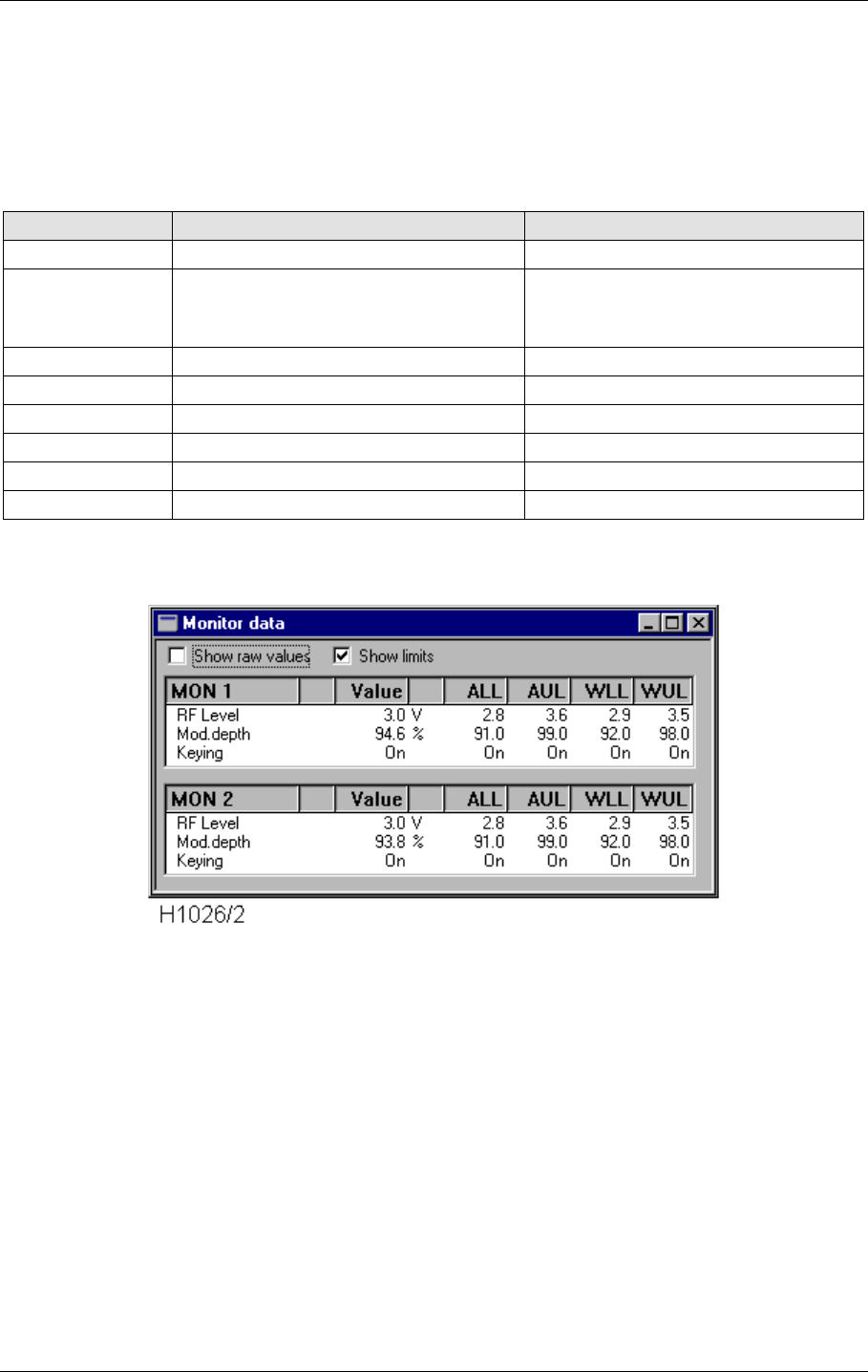
USER MANUAL
10-24
21464-5
NORMARC 7050
MARKER BEACON
Operation of RMM ©1999 Navia Aviation AS
10.5.8 Monitor windows
The Monitor view shows the primary parameters, RF LEVEL, MODULATION DEPTH and KEYING,
that is the parameters that may cause alarm and make the system change transmitter or shut
down. An alarm or a warning will be generated if the parameters value falls outside the ALARM
LIMITS or WARNING LIMITS respectively.
Table 10-12 Monitor parameter attributes
Figure 10-17 The Monitor view
You may edit the alarm and warning limits in access level three by selecting a parameter, and
click on the EDIT button that has popped up in the top right corner of the window. A double-
click on the parameter will do the same. You will now enter a edit dialogue for changing alarm/
warning limits.
Attribute Function Possible values
Name The name of the attribute Letters, numbers and spaces
Status Alarm/Warning status Blank = OK
w/W = raw/delayed warning
a/A = raw/delayed alarm
Value Calculated value (ax+b) A floating point number
Unit The unit of Value %, V
ALL Alarm Lower Limit A floating point number
AUL Alarm Upper Limit A floating point number
WLL Warning Lower Limit A floating point number
WUL Warning Upper Limit A floating point number
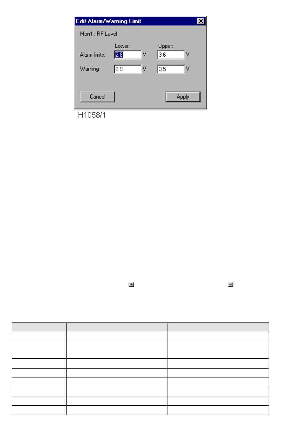
©1999 Navia Aviation AS 21464-5 Operation of RMM
USER MANUALNORMARC 7050
MARKER BEACON
10-25
Figure 10-18 The Monitor Edit window
Just type in the new values and press the APPLY button. The new limit values will now be
transferred to the marker beacon station.
See also the section for saving and loading limits and delays to/from file.
10.5.9 Maintenance
The maintenance parameters, which show the internal health of the NM7050, are organised in
a tree structure in three levels:
Station
Module 1.
Parameter1
Parameter2
Module 2. Parameter 1
Parameter2
The tree may be expanded by clicking the button and collapsed with the button. Each
parameter has several ATTRIBUTES, which are shown in a table structure in the Mainte-
nance view. The attributes are:
Table 10-13 Maintenance parameter attributes
Attribute Function Possible values
Name The name of the attribute Letters, numbers and spaces
Status Warning status Blank = OK
w/W = raw/delayed warning
Value Calculated value (ax+b) A floating point number
Unit The unit of Value %, V, W, A
WLL/WUL Warning Lower/Upper Limit Floating point numbers
Scale Scaling factor (a in ax+b) A floating point number
Offset Constant offset (b in ax+b) A floating point number
GW Generate Warning Yes, No (checked, unchecked)
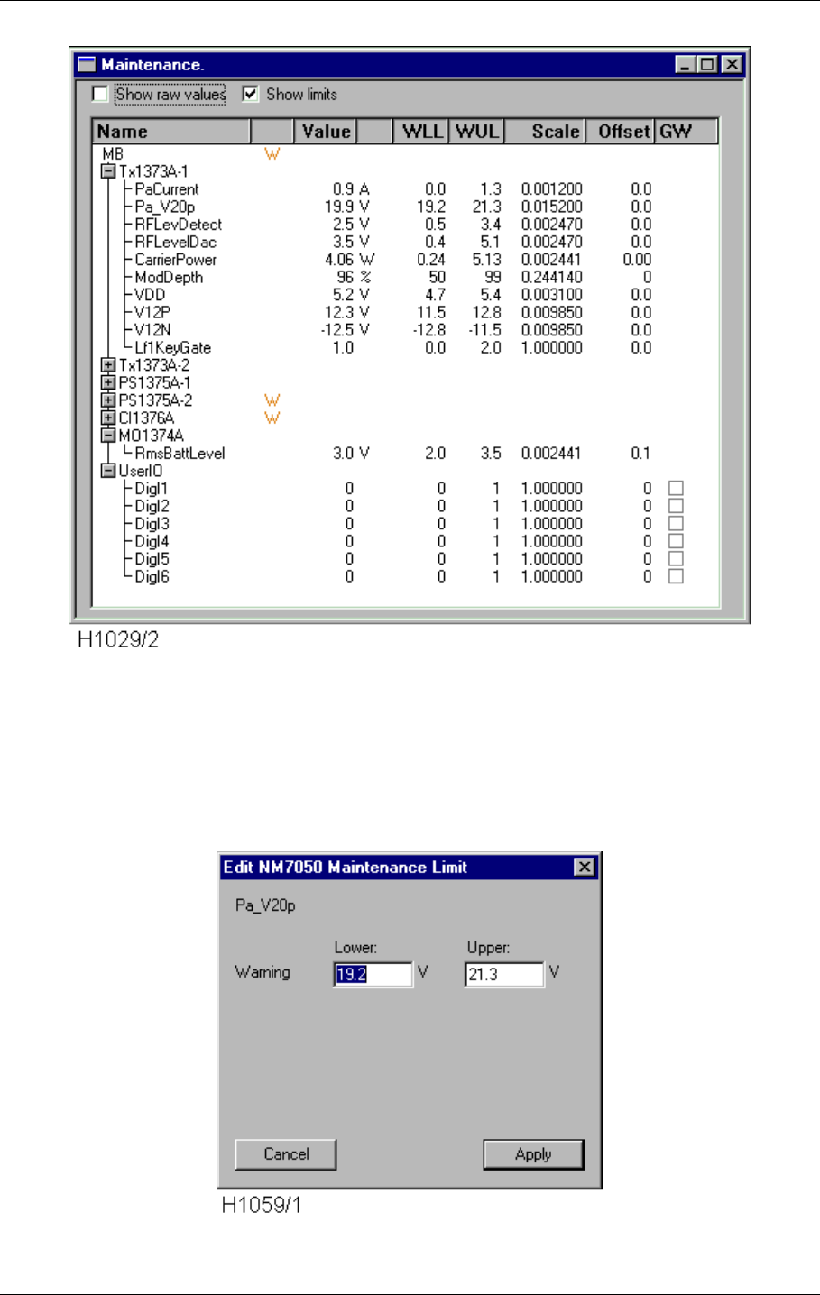
USER MANUAL
10-26
21464-5
NORMARC 7050
MARKER BEACON
Operation of RMM ©1999 Navia Aviation AS
Figure 10-19 The Maintenance view
You may edit the and warning limits in access level three by selecting a parameter, and click
on the EDIT button that will pop up in the top right corner of the window. A double-click on the
parameter will do the same. You will now enter a edit dialogue for changing warning limits,
which for the normal maintenance parameters may look like this:
Figure 10-20 The Monitor Edit window
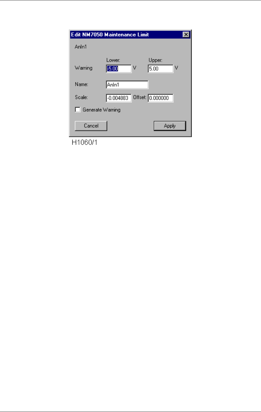
©1999 Navia Aviation AS 21464-5 Operation of RMM
USER MANUALNORMARC 7050
MARKER BEACON
10-27
Or like this for user maintenance parameters:
Figure 10-21 The Monitor Edit window
The NAME field is a user selectable name consisting of up to 10 characters. The SCALE field is
the factor the analogue input (range +/-10V) converted to a digital value (+2047 to -2048) will
be multiplied against. To convert to plain voltage level, the factor 10/-2048 = -0.004883 will do.
The GENERATE WARNING checkbox determines if the parameter shall generated maintenance
warning if the value exceeds the lower/upper warning limits.
When you have finished typing in the new values, press the APPLY button. The new limit val-
ues will now be transferred to the marker beacon station for update.
See also the section for saving and loading limits and delays to/from file.
10.5.9.1 Description of maintenance parameters
The maintenance parameters are located on various boards. The boards and the parameters
belonging to the specific board are listed here:
TX1373A-1
PaCurrent This is the current that is drawn from V20P in the RF Power Amplifier.
Pa_V20p This is the measured voltage for the +20V input.
RFLevDetect This is the analog RF-level value from the on-board detector on the transmit
ter.
RFLevelDac This is the DC-voltage controlling the carrier power.
CarrierPower This is the calculated carrier power output based on RFLevDetect.
ModDepth This is the calculated modulation depth from the on-board detector.
VDD This is the measured value for the +5V input power.
V12P This is the measured value for the +12V input power.
V12N This is the measured value for the -12V input power.
Lf1KeyGate This is the signal controlling the keying (modulation on/off) for the transmit
ter. The signal will be toggling between '0' and '1' when keying is ON, '0' when
keying if OFF and '1' when keying is CONT (continuous).

USER MANUAL
10-28
21464-5
NORMARC 7050
MARKER BEACON
Operation of RMM ©1999 Navia Aviation AS
TX1373A-2
Same parameters as for TX1373A-1
PS1375A-1
V28P This is the +28V power generated by the mains input. This will be low when
the NM7050 is running on battery power.
V20P This is the +20V power from this power supply.
VDD This is the +5V power from this power supply.
V12P This is the +12V power from this power supply.
V12N This is the -12V power from this power supply.
I28Vcurrent This is the current measurement for the current that is generated by the
mains power.
IBattCurrent This is the current that is going in/out of the power supply. Normally this
value will be positive when the mains power is charging the battery, and neg
ative when the system is operating on battery. However, when there are two
power supplies in the NM7050, the power supply with the highest +28V output
will actually charge the power converters on the other power supply. This will
be indicated by a negative value for this parameters on the other power sup
ply. To calculate the actual current that is charging the battery, the IBattCur
rent parameters for both power must be added together. For example if the
IBattCurrent for the two power supplies shows 1.4A and -0.5A, the actual
charge current to the battery is 0.9A.
PS1375A-2
Same parameters as for PS1375A-1
CI1376A
V28P The system +28V power, measured on the power line connected with the bat
tery.
V20P The system +20V power.
V12P The system +12V power.
VDD The system +5V power.
V12N The system -12V power.
TInDoor The temperature measured on the TEMP INDOOR connector inside the
NM7050 cabinet. At shipping the scale/offset is set for a 10mV/Co tempera
ture sensor, but the user may scale and offset this if wanted.
TOutDoor This is the temperature measured on the TEMP OUTDOOR connector inside
the NM7050 cabinet. At shipping the scale/offset is set for a 10mV/Co tem
perature sensor, but the user may scale and offset this if wanted.
Vac This is an input from a transformer that can be mounted in the NM7050 cab
inet for measuring the AC voltage. At shipping there is no transformer
mounted. When a transformer is implemented, the scale and offset must be
adjusted to suit the characteristics of the transformer. Keep in mind the this
input shall be a DC-voltage.
AnIn1 The analog user input from the analog channel marked ANA CH1 on
the CI1376A. The range is +/- 10V.
AnIn2 The analog user input from the analog channel marked ANA CH2 on the
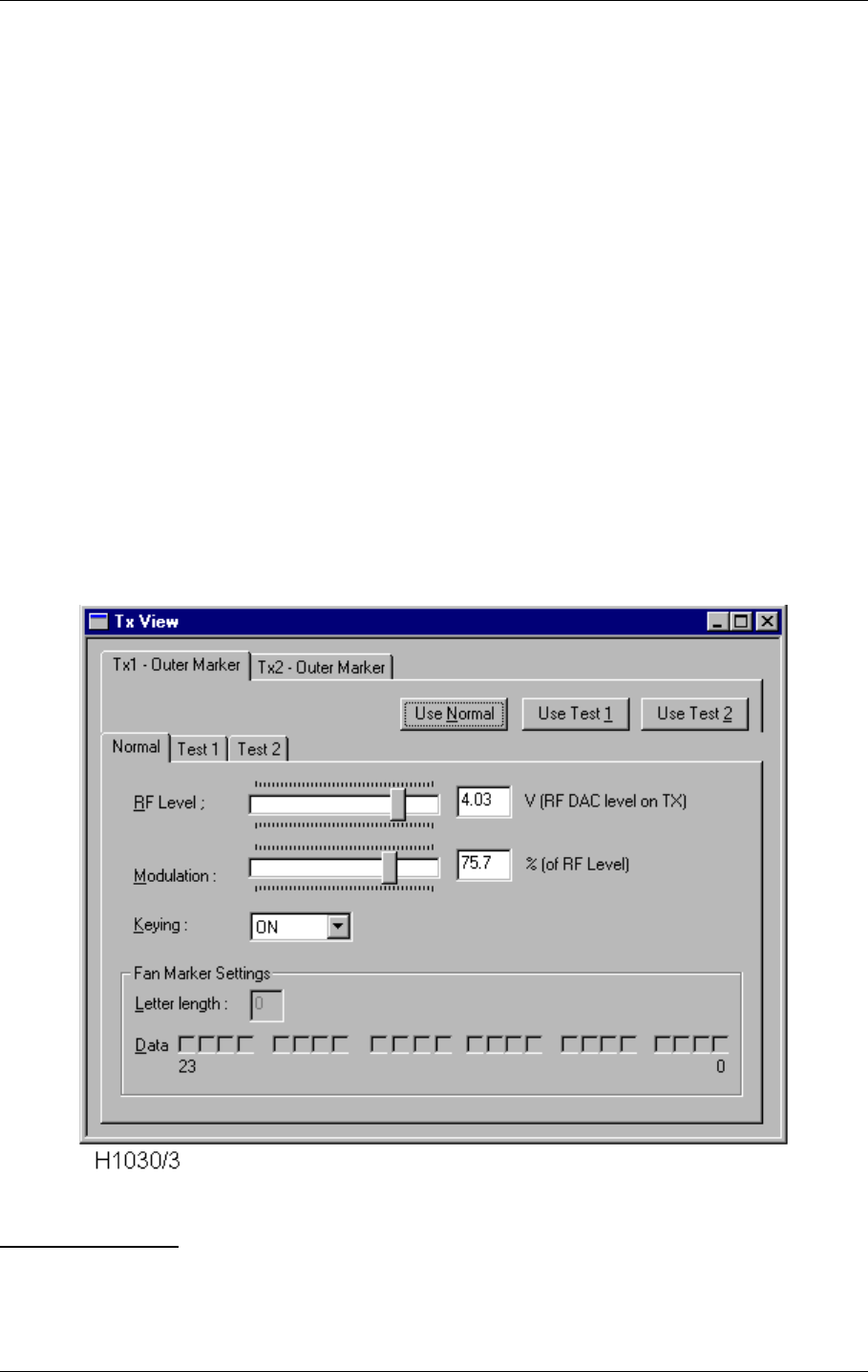
©1999 Navia Aviation AS 21464-5 Operation of RMM
USER MANUALNORMARC 7050
MARKER BEACON
10-29
CI1376A. The range is +/- 10V.
AnIn3 The analog user input from the analog channel marked ANA CH3 on the
CI1376A. The range is +/- 10V.
MO1374A
RmsBattLevel The measured voltage of the backup battery on MO1374A.
UserIO
DigI0 The digital input from DIG PORT A pin 3 on CI1376A.
DigI1 The digital input from DIG PORT A pin 1 on CI1376A.
DigI2 The digital input from DIG PORT B pin 3 on CI1376A.
DigI3 The digital input from DIG PORT B pin 1 on CI1376A.
DigI4 The digital input from DIG PORT C pin 3 on CI1376A.
DigI5 The digital input from DIG PORT C pin 1 on CI1376A.
10.5.10 TX settings
This view is used to tune the transmitters RF OUTPUT LEVEL, MODULATION DEPTH and KEYING.
There are also two test set-ups which are pre-set values used to provoke alarms in mainte-
nance situations.
Figure 10-22 The TX settings view
ALTERING VIEWS
• You may select between TX1 and TX2 by clicking the TX1 or TX2 tabs.
• You may select transmitter set-up by clicking the NORMAL, TEST1 or TEST2 tabs.
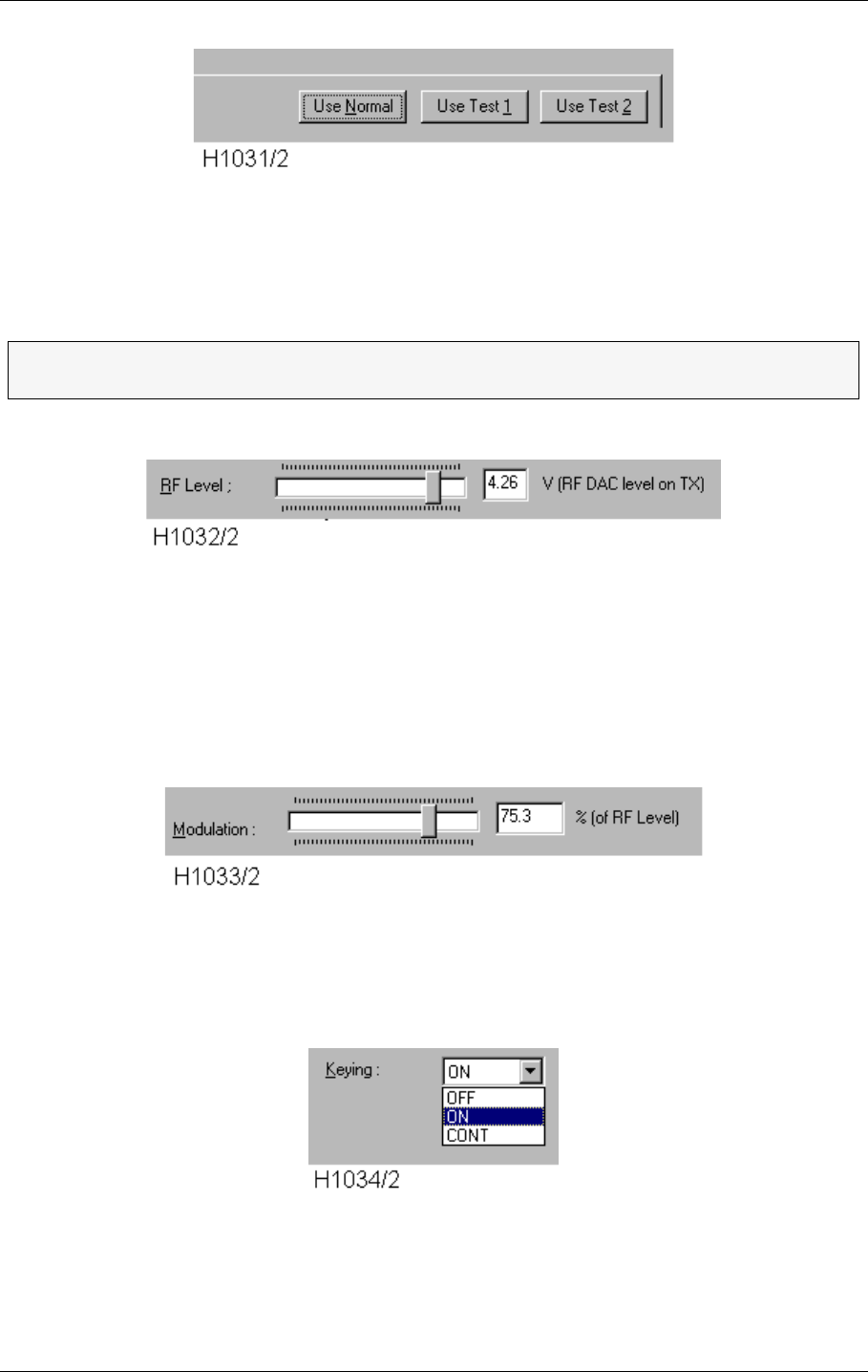
USER MANUAL
10-30
21464-5
NORMARC 7050
MARKER BEACON
Operation of RMM ©1999 Navia Aviation AS
Figure 10-23 Selecting test settings
You may choose between three pre-set transmitter settings by clicking the USE NORMAL, USE
TEST 1 or USE TEST 2 buttons.
Figure 10-24 Adjusting the RF level
The RF LEVEL (output power) is adjusted by dragging the RF LEVEL knob. The value in volts in
the window to the right shows the control voltage to the power amplifier. If you want a power
indication in Watts, open the maintenance window and watch the CarrierPower parameter for
the selected TX1373.
Figure 10-25 Adjusting the modulation depth
Similar to above, the MODULATION DEPTH is adjusted by dragging the MODULATION knob. The
value is given in percent. This percentage is not the same as the modulation depth in the mon-
itor, but the percent of the RF Level DAC that is used to feed the modulation circuitry in the
transmitter.
Figure 10-26 Setting keying type
There are three possible keying alternatives: NORMAL, CONTINUOS and OFF, the two latter
used for test or maintenance purposes.
ΤNote that when leaving access level 2/3, the Normal set-up will be loaded into the
transmitters. This is also the case when turning the transmitter from off to on.
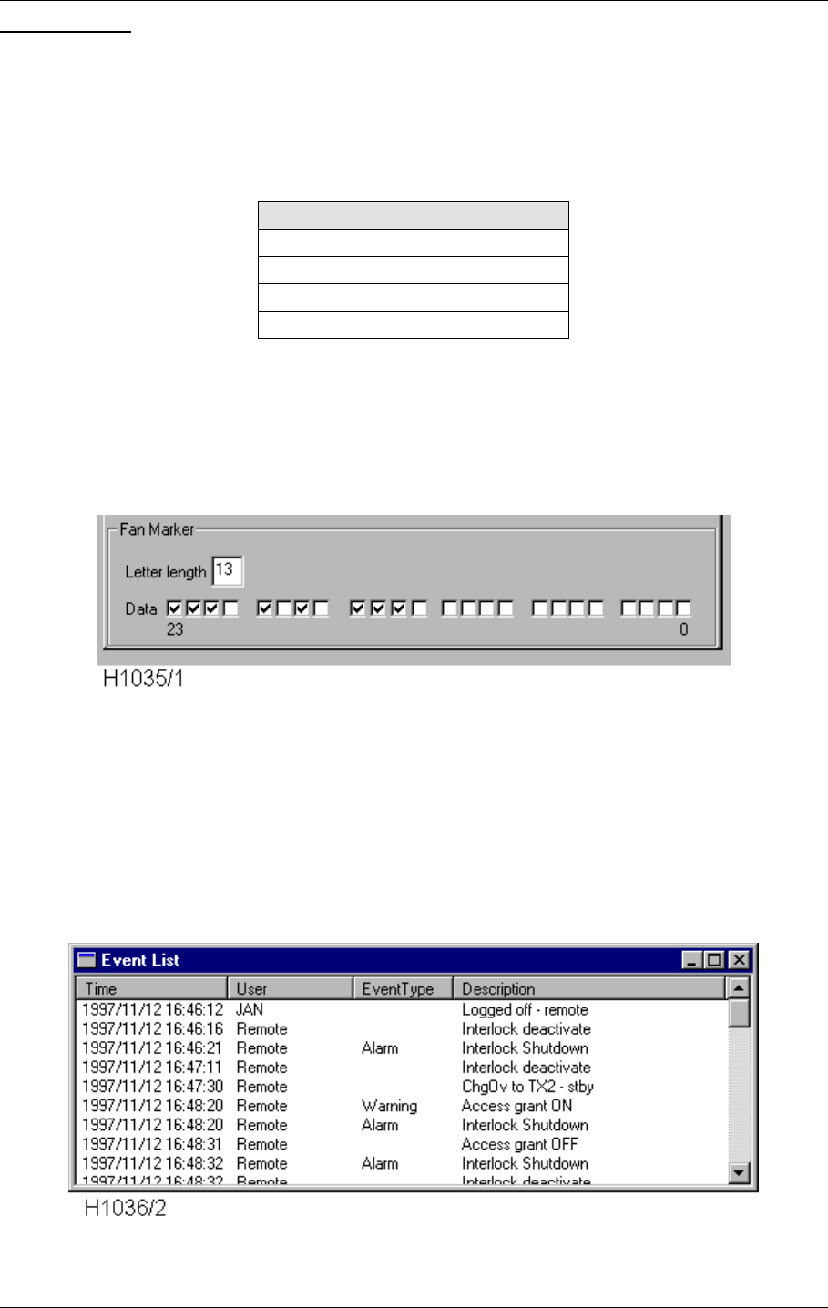
©1999 Navia Aviation AS 21464-5 Operation of RMM
USER MANUALNORMARC 7050
MARKER BEACON
10-31
FAN MARKER
If the station is configured as a FAN MARKER, the keying may be set quite freely. Each of the
24 Data boxes corresponds to one tick which endures for approximately 150ms. An X indi-
cates sound while an empty box indicates silence. LETTER LENGTH is how many ticks are used
in a sequence. The table below shows the expected lengths for keying elements:
Table 10-14 Fan Marker keying elements
Let's say you want to transmit an X. Then you should program DASH-SPACE-DOT-SPACE-DOT-
SPACE-DASH-LETTER SPACE. This gives a LETTER LENGTH of 3+1+1+1+1+1+3+2=13 as shown
in Abbildung 10-27
Figure 10-27 Fan marker keying programming.
Note that the Fan Marker settings are available only when the transmitter are configured as
Fan Marker.
10.5.11 Event list
The Event List shows the last 50 events for a specific Marker Beacon station. An event is for
example CHANGE OVER, SHUTDOWN, MAINTENANCE or WARNING. These events are stored in the
stations internal memory in order to diagnose errors.
Figure 10-28 The Event List
Keying element #ticks
Dot 1
Dash 3
Space 1
Letter space 2
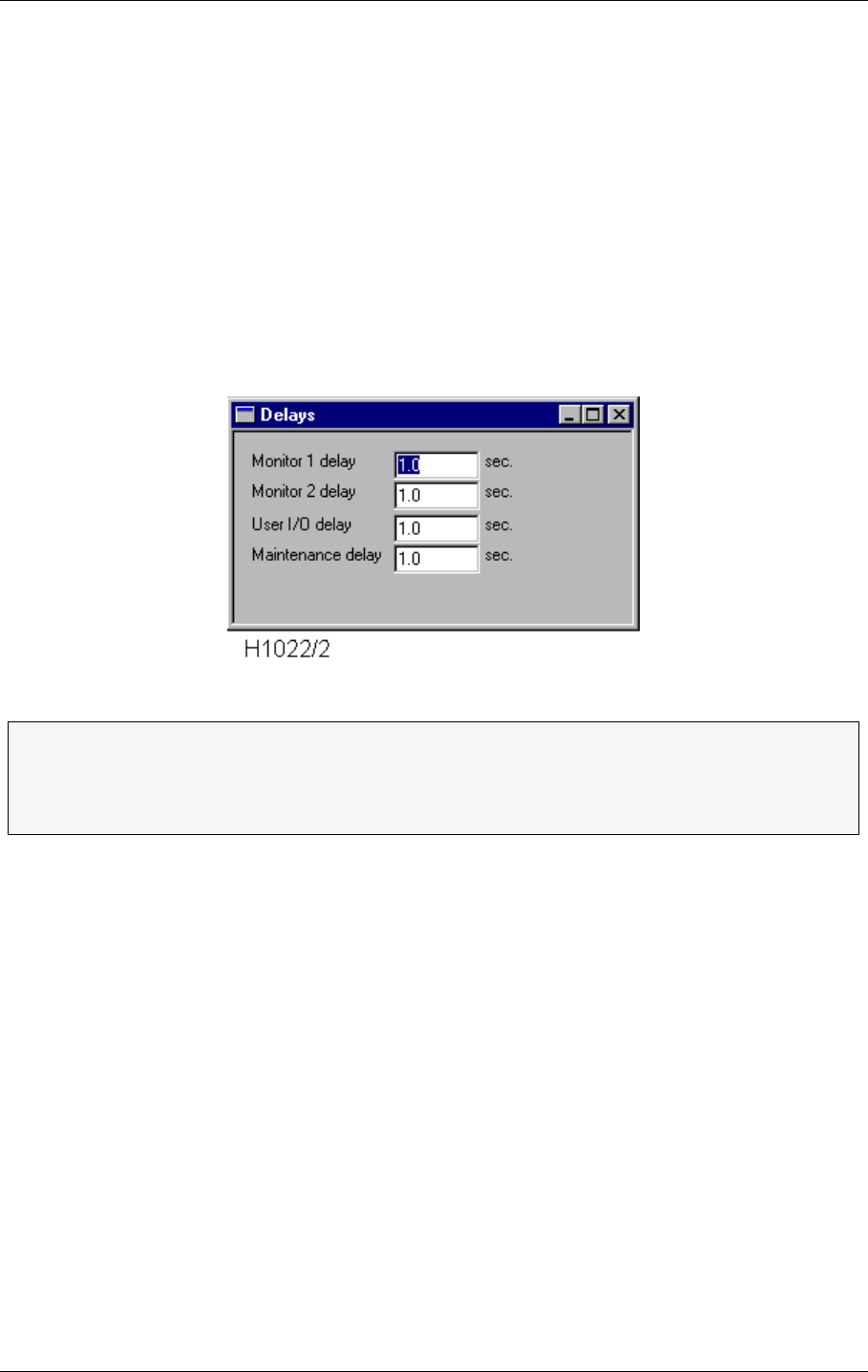
USER MANUAL
10-32
21464-5
NORMARC 7050
MARKER BEACON
Operation of RMM ©1999 Navia Aviation AS
When you have the Event List window up, new events will appear in the window as soon as
they are detected on the NM7050 and sent over to the PC program.
10.5.12 Delays
There are four individual alarm/warning delays in the NM7050:
• Monitor 1 alarm/warning delay
• Monitor 2 alarm/warning delay
• Maintenance parameter delay
• User input/output parameter delay
You specify the delay in seconds and activate the new settings with APPLY, which pops up
whenever a delay is changed.
Figure 10-29 The Delay view
10.5.13 Printing Reports
Printing the reports is done simply by clicking the printer button. You will then enter the dia-
ΤA delay in this context is the time an alarm or warning must be present before the
Transmitter Control performs a Changeover or Shutdown.
ΤUSER IOS are the analogue and digital input and output ports located on the con-
nection interface board (CI 1376) inside NM7050.
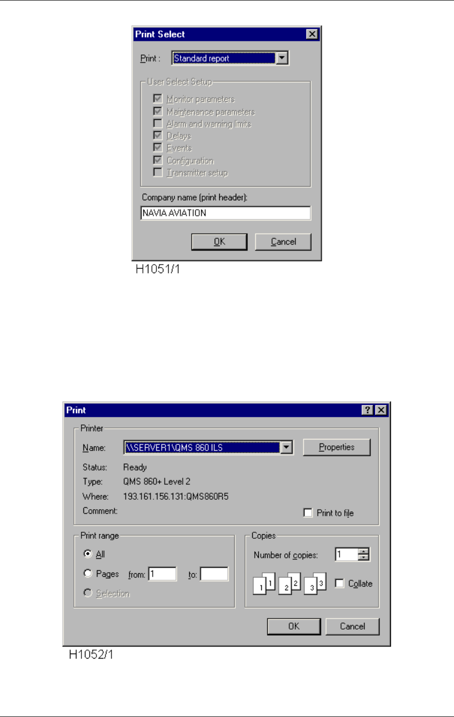
©1999 Navia Aviation AS 21464-5 Operation of RMM
USER MANUALNORMARC 7050
MARKER BEACON
10-33
logue for report selection.
Figure 10-30 The Print Select dialogue
Here you can select a the report type you want. Either a standard report, a full report or a
report containing the elements you specify. You may also choose the name that will be printed
on the top of the report in the COMPANY NAME field.
Press OK when you are finished, and the standard windows print dialogue appears. When
you have done you choices, select the OK button for generating a report on the printer that is
specified in the NAME field.
Figure 10-31 The Standard Print dialogue
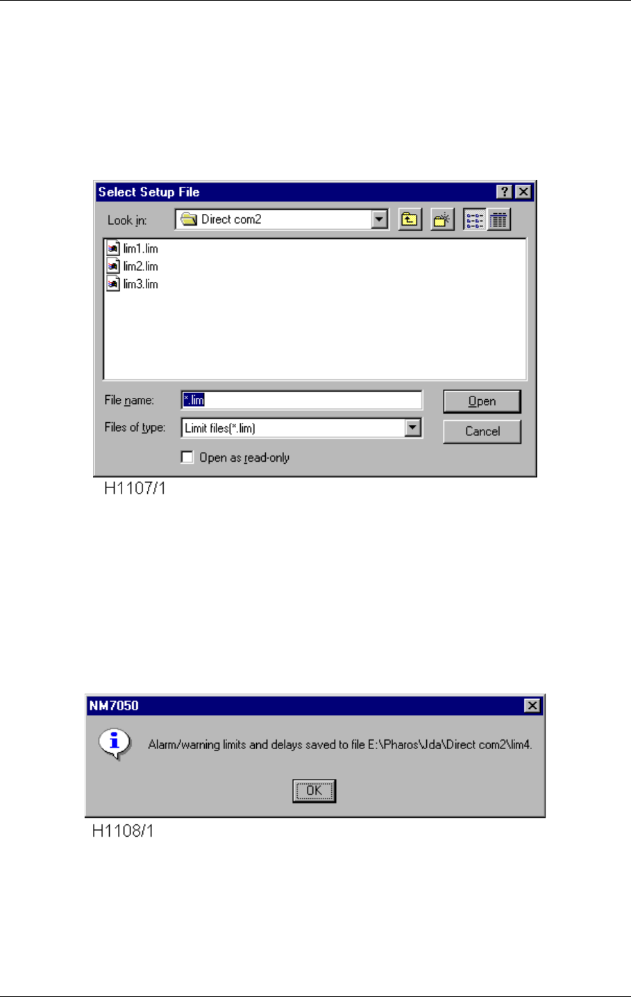
USER MANUAL
10-34
21464-5
NORMARC 7050
MARKER BEACON
Operation of RMM ©1999 Navia Aviation AS
10.5.14 Loading and saving alarm/warning limits and delays
To ease setting of alarm limits, warning limits and delay settings, the user is provided with the
Save NM7050 Setup and Load NM7050 Setup commands in the File menu.
To save the settings on a NM7050 to a file, choose File|Save NM7050 Setup. The following
dialog appears.
Figure 10-32 The Select Setup File Dialog
Type in a new filename if you want to create a new one, or select a file to replace it. Press
Open to proceed or Cancel to escape.
If Open was selected, the setup for the currently opened station will now be saved as a text
file (<name>.lim), and the following information should appear, with the filename you have
selected
Figure 10-33 The Setup Save OK messagebox
To load settings from a file and apply them to the currently opened NM7050, choose menu
item File|Load NM7050 Setup. The same dialog as for the Save NM7050 Setup should now
appear. Select the file that contains the setup you want, and press the Open button. The fol-
lowing view should now appear:

©1999 Navia Aviation AS 21464-5 Operation of RMM
USER MANUALNORMARC 7050
MARKER BEACON
10-35
Figure 10-34 The Setup Select View
Select which parts of the setup you actually want to load. By default everything is selected.
When selection is satisfactory, press the Load Settings button. The progress bar in the top of
the view will now increase until all parameters/delays are properly set. This may take some
time, especially for the maintenance settings, so be patient.
You must have access level 3 or higher to be able to load settings from file.
10.5.15 Tool options
From Tool Options the secondary parameters and facilities are configured. The options are
organised in different pages that are accessed through selecting the different tabs in the dia-
logue. Note that the settings you specify are directly executed when selecting an APPLY button
in one of the option pages. The CANCEL button will not redo these changes.
10.5.15.1The Data Logging Page
From the Data Logging page you may specify regular logging of data to hard disk files. Log-
ging of Maintenance and Monitor data is done to separate files.
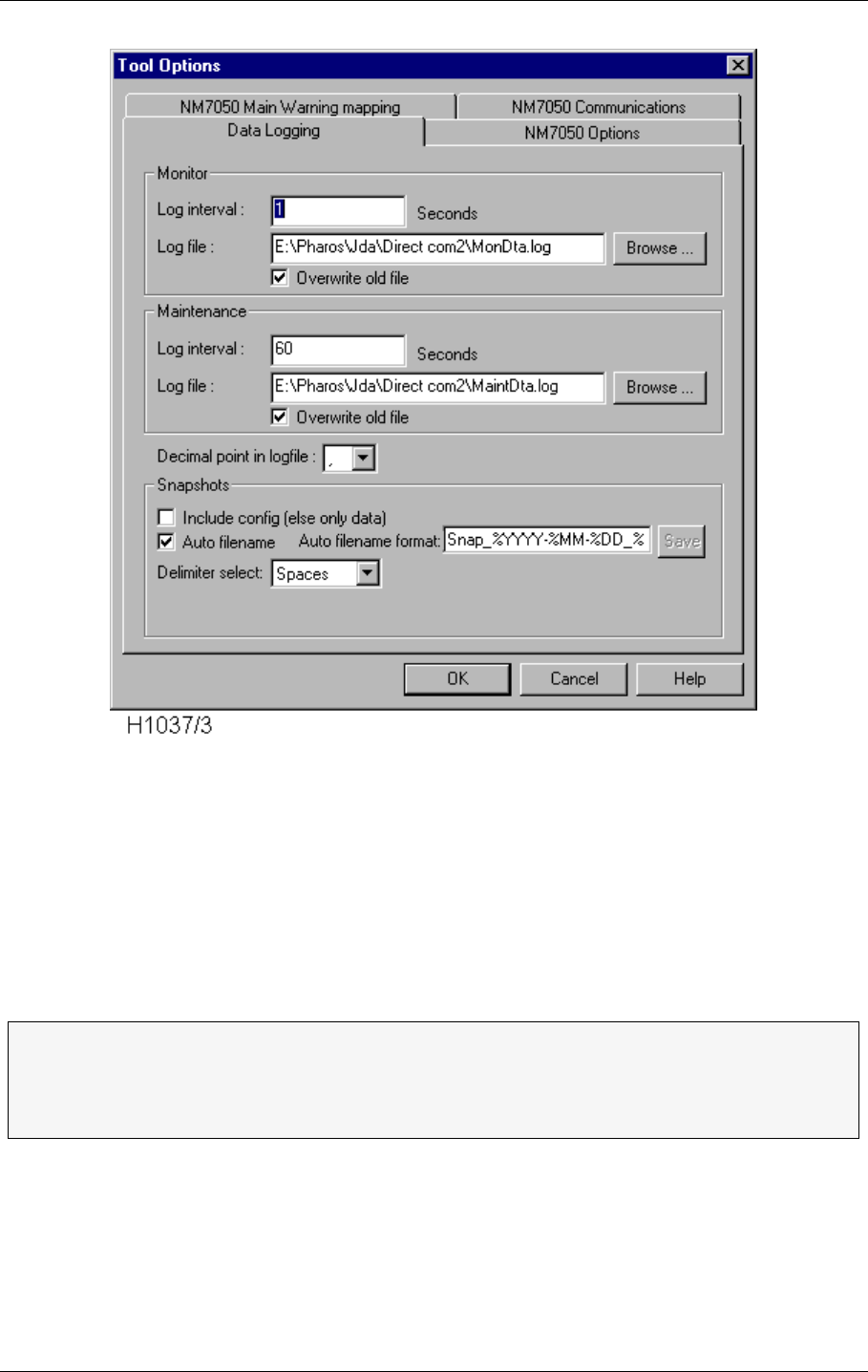
USER MANUAL
10-36
21464-5
NORMARC 7050
MARKER BEACON
Operation of RMM ©1999 Navia Aviation AS
Figure 10-35 The Tool Options Data Logging page.
• The time between two samples, the LOG INTERVAL, must be given in seconds.
• The LOG FILE name may be written directly, The standard directory is a directory with the
same name as the station you logged on to (the directory is created automatically when
you log on if it don't exist), or you may BROWSE for the file/directory you want your log file in.
• If you activate OVERWRITE, you will erase the data in an existing file. When OVERWRITE is
deactivated (blank field) you append the data to an existing file.
• The Decimal point in log file field is used to select between a dot or a comma as the deci-
mal point in the log values (this is done for exporting compatibility to other programs).
You may also alter the snapshot function. A snapshot in this context is a text file containing a
snapshot of the current monitor and maintenance data. The snapshot is taken whenever of
the menu selection File|Snapshot or Snapshot toolbar button is selected. Both of the Monitor
and Maintenance views must be activated before a snapshot may be taken (to ensure fresh
monitor and maintenance data).
If the Include config (else only data) checkbox is checked, the snapshot will also include con-
ΤTip: Name your files with date info, i.e. log199707 for July 1997 for easy locating of
files later on.
ΤThe files are stored in a format which makes it easy to import in for example Excel.
Just drag and drop a log file over the Excel icon on your desktop.

©1999 Navia Aviation AS 21464-5 Operation of RMM
USER MANUALNORMARC 7050
MARKER BEACON
10-37
figuration (alarm and warning limits).
If the Auto filename is checked, the text in the Auto filename format field will be used to gener-
ate the filename where the snapshot is placed. If not checked, the user may select a file by a
standard file browser. The filename format may contain directly text or codes that will insert
the current date/time value according to the following rules:
• %YY[YY] The current year is inserted
• %M[M] The current month (1-12)
• %D[D] The current day (1-31, depending on month and year)
• %H[H] The current hour (0-23)
• %m[m] The current minute (0-59)
• %S[S] The current second (0-59)
• %T The current tenth of a second (0-9)
For example the string
SNAP_%YYYY-%MM-%DD_%HH.%mm.%SS.txt
will give a filename such as
SNAP_1998-10-30_14.39.16.txt
You may also select how to separate the elements of the snapshot by selecting in the droplist
Delimiter select. This may be useful if special formatting is wanted for exporting to certain pro-
grams. You may select between
• Spaces Text is formatted for best reading using a standard text editor.
• Tabs Tab character is inserted between data elements.
• :(Colon) The colon character is inserted between data elements.
• ;(Semicolon) The semicolon character is inserted between data elements.
10.5.15.2The NM7050 Options page
From this page you can change the real time clock in the NM7050. In addition you may config-
ure your NM7050 to not set the station in SERVICE condition if the Write Protect switch is
turned off. From this dialogue you can also override the interlock if the Local/Remote and
Auto/Manual switches are in Local/Manual. This option is only valid when the interlock is
active (meaning that the NM7050 is forced off by the interlock switch in the tower). You may
also specify the periodic interval for logging of history storage (not implemented in the first ver-
sion of the program).
• If you press PC CLOCK, DATE and TIME field are filled with the date and time on your PC.
The value is loaded into NM7050 when you press the APPLY button. The APPLY button will
only be shown when there are changes in the DATE and TIME fields.
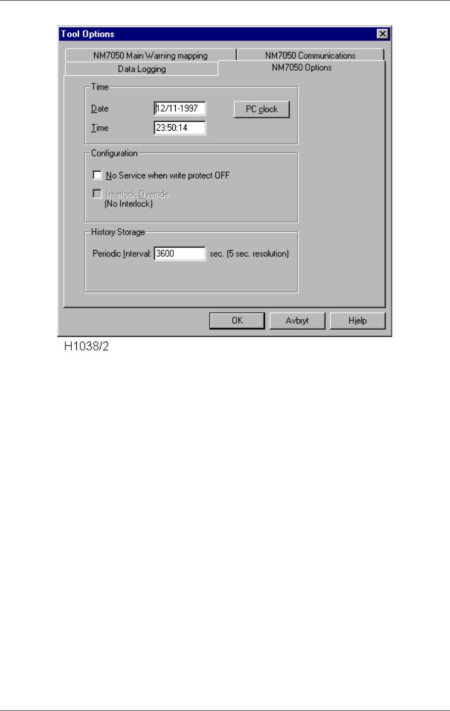
USER MANUAL
10-38
21464-5
NORMARC 7050
MARKER BEACON
Operation of RMM ©1999 Navia Aviation AS
Figure 10-36 The Tool Options NM7050 Options page.
10.5.15.3The NM7050 Main Warning mapping page
The sub-warning to main warning mapping can be programmed individually for the local front
panel and the remote control panel. This means that the user can select which sub-warnings
that will generate a system warning for the station both locally and remotely. Checking all
selections (factory default) will make any sub-warning generate a system warning on the
NM7050.
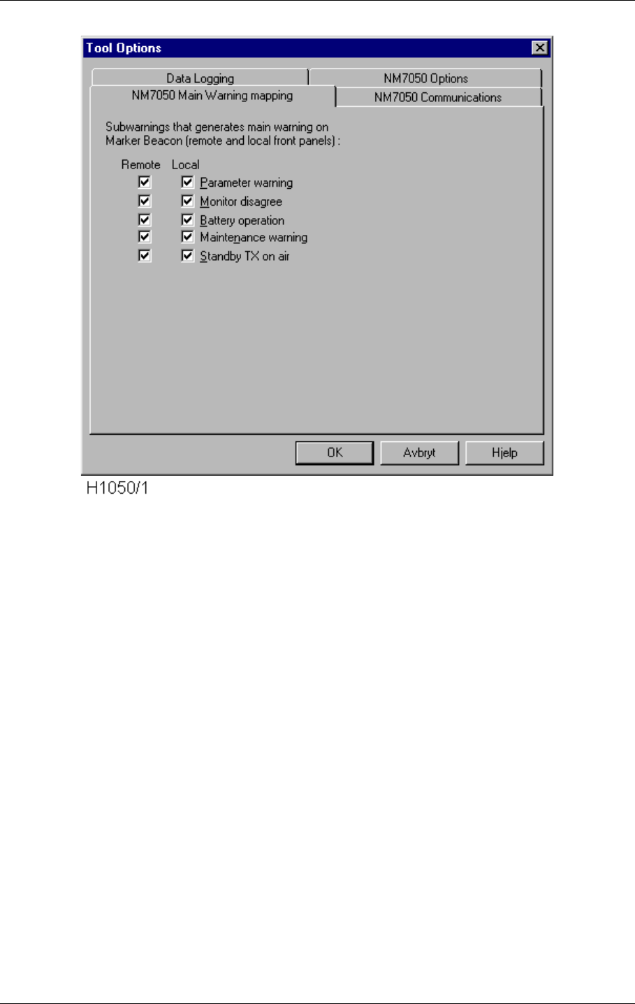
©1999 Navia Aviation AS 21464-5 Operation of RMM
USER MANUALNORMARC 7050
MARKER BEACON
10-39
Figure 10-37 The Tool Options NM7050 Main Warning mapping page.
These settings are available only with access level 3 or higher.
10.5.15.4The NM7050 Communications page
This page is used for setting up communication for the remote RS232 connection. Typically
the user has logged on directly using the local RS232 port for setting up a modem connected
to the remote RS232 port. From this options page you can set up both local and remote com-
munication settings.
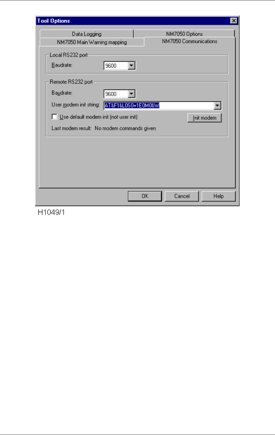
USER MANUAL
10-40
21464-5
NORMARC 7050
MARKER BEACON
Operation of RMM ©1999 Navia Aviation AS
Figure 10-38 The Tool Options NM7050 Communications page.
10.5.15.4.1Local RS232 port settings
Here you can specify the baudrate you want to use when communicating with the NM7050
through the local RS232 port.
10.5.15.4.2Remote RS232 port settings
Here you can specify the baudrate and modem initialisation for the remote RS232 port. The
BAUDRATE field let you select the baudrate the NM7050 will use when communicating using
the remote RS232 port. The USER MODEM INIT string lets you specify the init string that will be
sent to the modem at restart of the NM7050 program. If you want to use this string at start-up,
you must uncheck the USE DEFAULT MODEM INIT checkbox. Unless this is done, the default
modem init string within the NM7050 is used.
10.5.16 Administration
The System Administrator , who has access to the Master-account has several rights that
other users do not have. These are:
• Create new users
• Delete users
• Changing the users access rights
• Tell a preoccupied engineer his/her forgotten password.
In order for the system administrator to do this, he/she must first log on as master with three
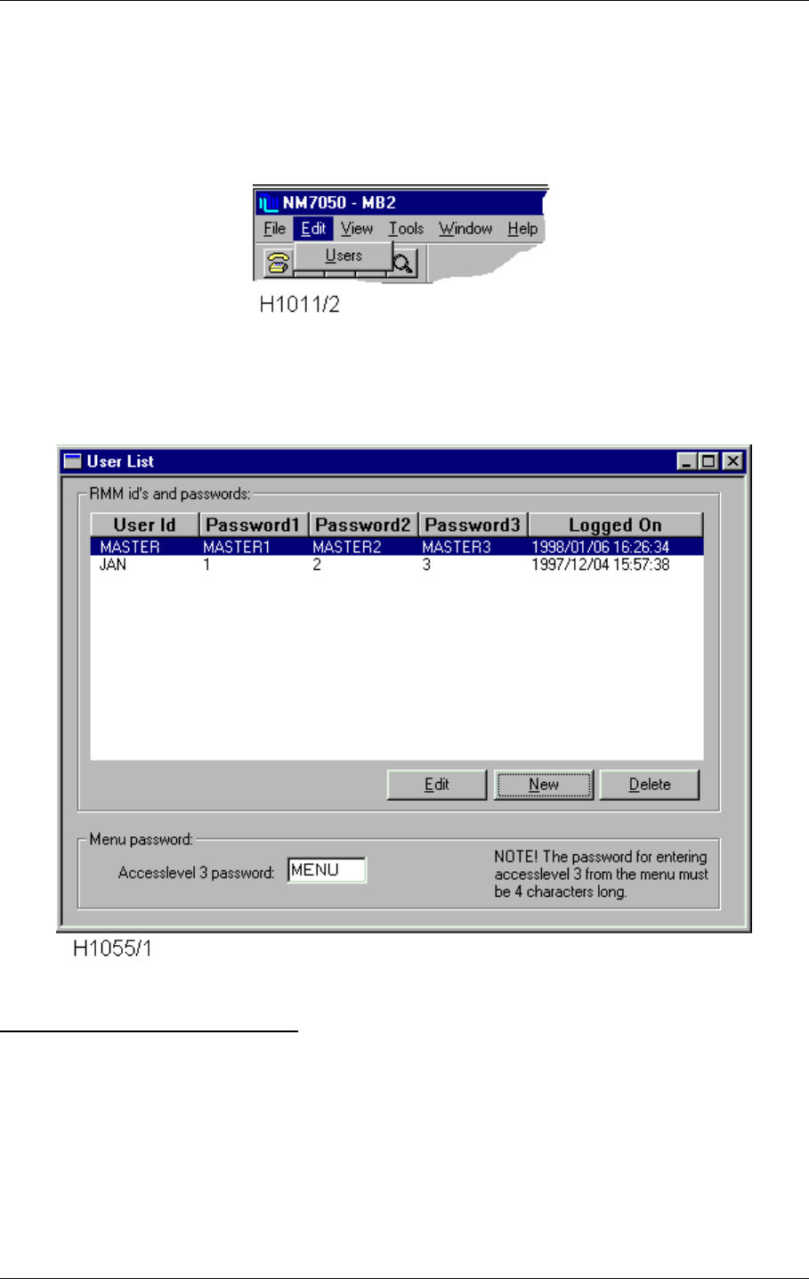
©1999 Navia Aviation AS 21464-5 Operation of RMM
USER MANUALNORMARC 7050
MARKER BEACON
10-41
valid passwords on the local RS232 port. The Local/Remote and Manual/Auto switches must
be in Local/Manual position, and the Write Protect switch must be up. After having logged on
and having connected to the system, the system administrator has access level 3 on the sys-
tem in addition to the master user privileges (sometimes called access level 4). You may now
select the Edit | Users menu.
Figure 10-39 The Edit | User menu choice.
The Edit Users window will now appear, and you may do you changes.
Figure 10-40 The Edit Users window.
RMM USER ID AND PASSWORD
To delete a user simply click on the user to delete, and then select the Delete button.
To create a new user, just select the New button.
To edit a current user, click on the user and then select the Edit button.
For creating new and edit current users, the following dialogue pops up (the user id and pass-
words will not necessarily be the same as in the figure below) :
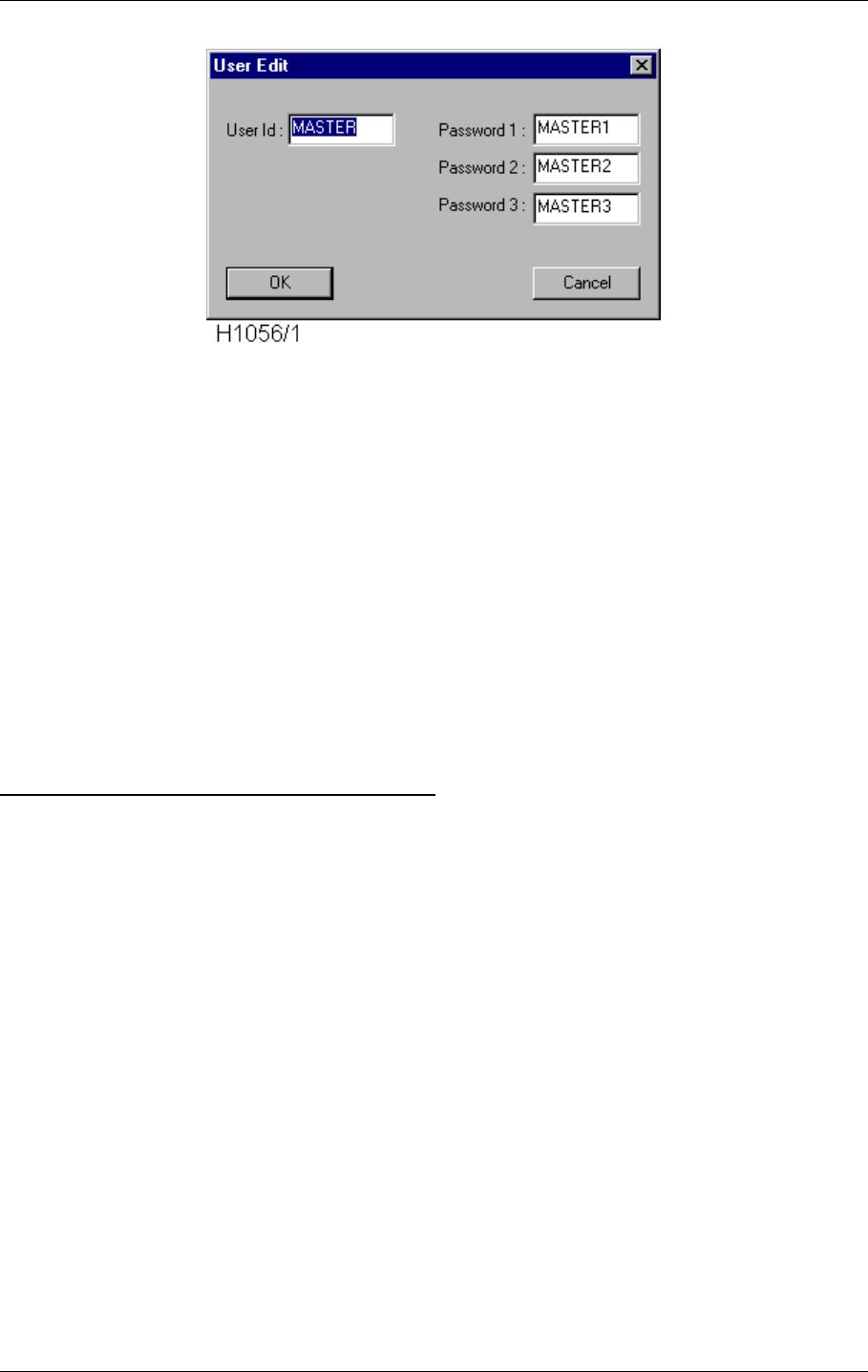
USER MANUAL
10-42
21464-5
NORMARC 7050
MARKER BEACON
Operation of RMM ©1999 Navia Aviation AS
Figure 10-41 The Edit User dialogue.
The following rules applies for the Edit User dialogue:
• The user id and password must at least contain 1 characters, but no more than 8 charac-
ters.
• The number of filled in passwords define the maximum access level for that user. For
example if passwords 1 and 2 are filled with strings, that user can log in with either access
level 2 or access level 3.
• A user must have at least Password 1 defined.
• User Id and passwords can be selected freely.
• All letters are converted to uppercase.
• There is a maximum of 15 users in the system.
When you are satisfied with the id and passwords, select the OK button, and the NM7050 will
be instructed to insert a new user/change an existing user. When the NM7050 responds, the
User View will be updated with the new values.
MENU USER ACCESS LEVEL 3 PASSWORD
To enter access level 3 through the local keyboard, the user must first enter a correct four let-
ters password (besides setting the LOCAL/REMOTE and WRITE PROTECT switches in
LOCAL and OFF positions). The password is set by changing the Access level 3 password
field to a new four letters password, and then select the Apply button. The Apply button pops
up only when the password has changed, and there are four letters in the Access level 3 pass-
word field.

©1999 Navia Aviation AS 21464-5 Periodic maintenance
USER MANUALNORMARC 7050
MARKER BEACON
11-1
11 Periodic maintenance
The NM7050 Marker Beacon has an extensive Remote Monitor and Maintenance (RMM)
system. This remote facility, which makes the user able to perform most of the maintenance
from the airport, is particurlarly useful for marker beacons since their location is up to 7 km
away.
The periodic maintenance is splitted in two parts, monthly remote maintenance and annual on
site maintenance..
11.1 Reference Report
Print out a standard report after commisioning. This will serve as a reference for later inspec-
tions. This Reference Report should be kept updated if changes are made to alarm or warn-
ing limits.
11.2 Monthly inspection
The monthly inspection is most practically performed from the control tower. Dump the cur-
rent state of the Marker Beacon parameters to either printer or file from the RMM program.
To printer: Select FILE-PRINT REPORT from the menus or click the PRINT button.
To file: Select FILE-SAVE REPORT from the menus or click the SAVE button.
11.2.1 Parameter check
Check that the parameters are well within their alarm and warning limits. Also check that the
alarm and warning limits corresponds with the Reference Report.
11.2.2 Monitor check
Provoke alarm situations with the test settings and check that the monitor generate the corre-
sponding alarm and performs a transmitter change over. The easiest way is to make sure the
preprogrammed test settings sets RF LEVEL, MODULATION DEPTH and KEYING outside the alarm
limits.
•Set ACCESS GRANT on the Remote Control
•Set REMOTE mode on the Front Panel in the RMM program
•Set AUTOMATIC mode on the Front Panel in the RMM program
• Log in on ACCESS LEVEL 2
• Set an alarm generating test setting on the main transmitter in TX settings
• Check that RF LEVEL, MODULATION DEPTH and KEYING are in ALARM state
• Check that a CHANGE OVER is performed
• Set an alarm generating test setting on the standby transmitter in TX settings
• Check that RF LEVEL, MODULATION DEPTH and KEYING are in ALARM state
• Check that a SHUTDOWN is performed
ΤEven though the on site maintenance is once a year, a more frequent visual inspec-
tion is recommended. The Markers are often located in non trafficated areas
where unwanted guests or mother nature may work in peace.

USER MANUAL
11-2
21464-5
NORMARC 7050
MARKER BEACON
Periodic maintenance ©1999 Navia Aviation AS
.
11.2.3 Remote Control check
Check the Remote Control connection by performing remote control actions and watch the
response on the virtual Front Panel in the RMM program.
• Open the RMM Front Panel
• Perform a change over from the Remote Control
• Check that the action is reflected on the RMM Front Panel
• Disconnect the Remote Control
• Check that an alarm is generated and a shutdown performed
11.2.4 Main select
In order to keep the reliability of the two transmitters equally high, it is recommended to per-
form a MAIN SELECT every month.
11.3 Annual inspection
• Perform the monthly inspection
• Check that the carrier frequency is 75 MHZ +/- 0.005%
• Check that the modulation frequency is:
•With continous keying, check that the harmonic contents of the modulation tone is less than
8% of the tone..
If the configuration of the NM 7050 disables STANDBY FAILURE SHUTDOWN, the
SHUTDOWN will NOT be performed. The configuration is reported in the Link Sta-
tus window.
If the configuration of the NM 7050 disables REMOTE CONTROL FAILURE SHUT-
DOWN, the SHUTDOWN will NOT be performed. The configuration is reported in the
Link Status window.
Outer Marker 400 Hz ±10 Hz
Middle Marker 1300 Hz ±32 Hz
Inner Marker 3000 Hz ±75 Hz
If you want more detailed statistics, you may dump the Periodic Storage to a file.
The file may be imported to spreadsheets or other programs that do statistic analy-
sis and/or graphical presentations. The sample period of the Periodic Storage is
programmable.
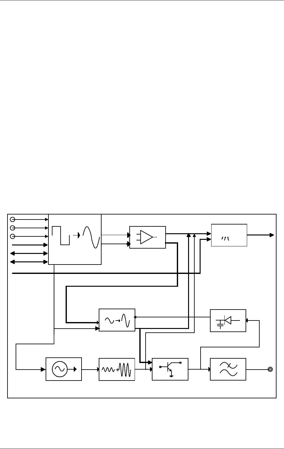
©1999 Navia Aviation AS 21464-5 Detailed Description
USER MANUALNORMARC 7050
MARKER BEACON
12-1
PART IV DESCRIPTION
12 Detailed Description
This chapter describes the modules in detail.
12.1 Main Cabinet
12.1.1 TX 1373A Transmitter
12.1.1.1 General Description
TX 1373A is a module designed to transmit Marker Beacon signals. An on board oscillator
working at 75 MHz provides an output of app.0 dBm that is used as input to the Power Ampli-
fier (PA). The level of this input signal is adjusted to an output of app. +20 dBm. The Power
Amplifier is capable of delivering up to 4W carrier power at the cabinet output.
Unwanted frequencies are removed by a lowpass filter after the PA. Part of the signal out of
the PA is tapped off to be demodulated and used for feedback and self test purposes. Demod-
ulation is done by a mixer with a linear detector.
The audio signals are generated in the LF circuitry mainly by a Field Programmable Gate
Array (FPGA). Inner, Middle or Outer Marker is selected by straps.
12.1.1.2 Block diagram
Figure 12-1 TX1373 Block diagram
12.1.1.3 Signals
Oscillator
Modulation detector
LP filter
Power Amplifier
Automatic Gain Control
RF OUT
LF Generator
Maintenance/
Monitor
Modulation Amp
Modulation Control
AMUX_A[3:0]
DAC_DATA[7:0]
DAC_CTRL
MODULATION / BIAS
RF LEVEL / IDENT
MAINTENACE SIGNALS
DET_SIGNAL
TXCS
TXWR
TXRD
IOD[7:0]
TX_CTRL_BUS
TRANSMIT
TRANSMIT
RMS_LEV[1:0]
A_TX[P,N]
HBK817-1
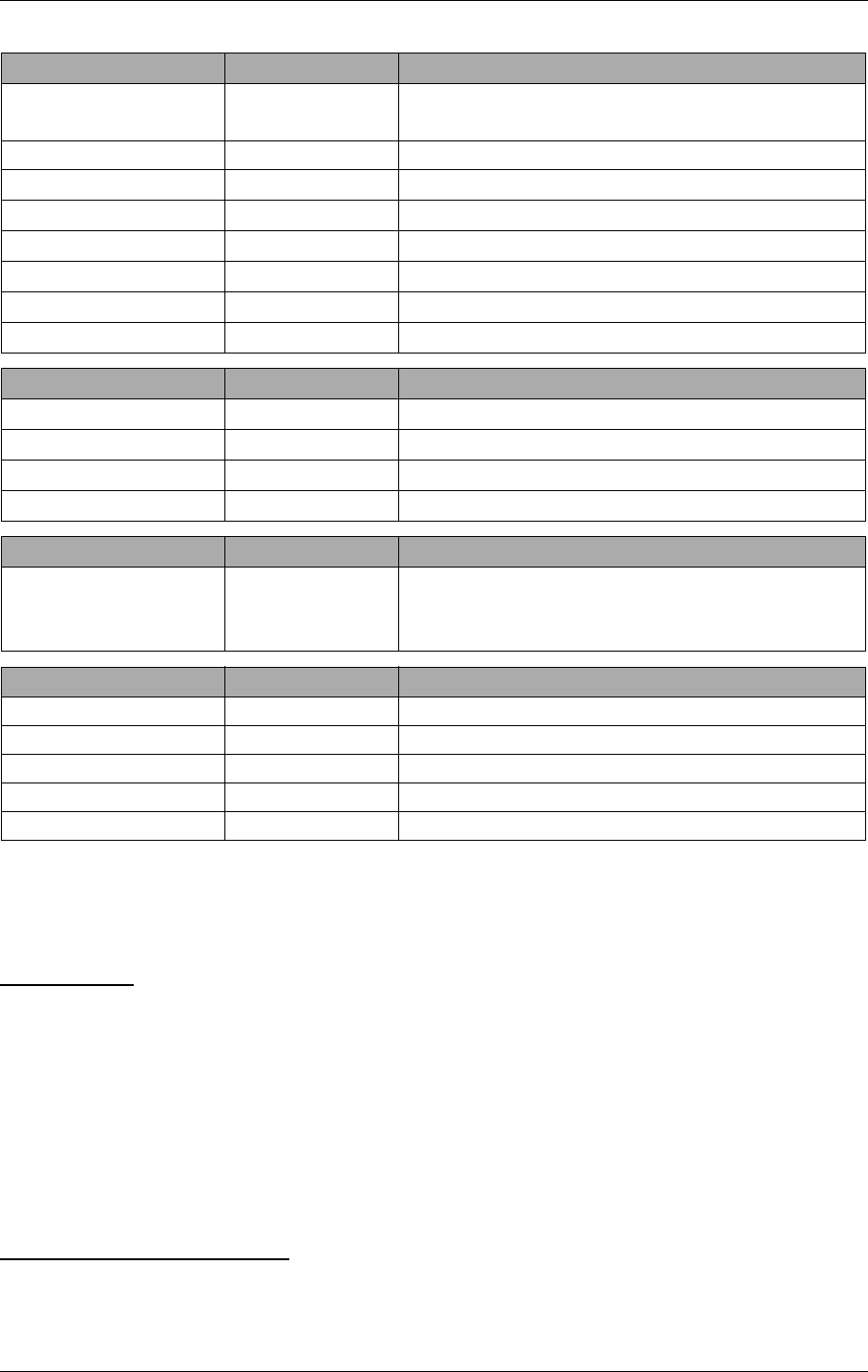
USER MANUAL
12-2
21464-5
NORMARC 7050
MARKER BEACON
Detailed Description ©1999 Navia Aviation AS
(See block diagram Figure12-1)
12.1.1.4 Building blocks
(See block diagram Figure12-1)
OSCILLATOR
The oscillator is controlled by the Transmit signal from the LF generator. When Transmit is
low, a controllable voltage generator turns the internal oscillator 12V voltage on. +12 VDC is
then applied to the collector of a bipolar transistor, which is the active device of the oscillator.
A 75 MHz crystal is connected in the feedback path together with a resonance circuit.
The output signal is amplified to approximately 0 dBm through a RF gain block.
Signals in: ON/OFF to switch oscillator on.
Signals out: RF to AGC
AUTOMATIC GAIN CONTROL
The AGC circuitry is designed to adjust the signal level from the oscillator to the PA. The sig-
nal from the oscillator is fed to one of the ports of a dual gate MOSFET. The signal enters the
In From Description
IOD[7:0] MO 1374 Parellel data bus for communication between TX
1/2, CI and MO1
~TXCS MO 1374 Transmitter card select
~TXWR MO 1374 Write strobe for IO bus
~TXRD MO 1374 Read strobe for IO bus
TX_ADR CI 1376 Transmitter select
TX_ON MO 1374 Transmitter on/off
AMUX_A[3:0] MO 1374 Used to select measurement
~RMS_LEV[1:0] MO 1374 Signals access level for RMS
Out In Description
RF_OUT Antenna Radio signal
∼TX_FB MO 1374 Signal tells monitor that transmitter is active
A_TX[P,N] RMS RMS analogue test signals
∼TXCSB MO 1374 Transmitter card select back
Bidirectional To/From Description
TX_CTRL_BUS MO 1374 Changeover Control (TX_ADR), transmitter on/
off (TX_ON), card select back (TXCSB), feed
back (TX1/2_FB)
Power in From Description
V20P PS 1375 +20 VDC to PA
V12P PS 1375 +12 VDC
VDD PS 1375 +5 VDC
GND PS 1375 Analogue ground
V12N PS 1375 -12 VDC

©1999 Navia Aviation AS 21464-5 Detailed Description
USER MANUALNORMARC 7050
MARKER BEACON
12-3
PA after being amplified, while part of it is fed back to the other port of the MOSFET. The
transistor detects the difference between these two signals and increases or decreases the
signal out to the PA, depending on the signal levels from the oscillator.
Signals in:7 5 MHz RF from oscillator.
Signals out: RF to PA, app. +20 dBm
DRV_AGC: control voltage to monitor.
POWER AMPLIFIER
The Power Amplifier stage is implemented by three cascaded stages, with the two first
being bipolar MRF 553 transistors that are collector modulated. The modulation voltage is 0-
12VDC both at stage one and stage two. With an input signal from oscillator / AGC of +20
dBm, the first stage will deliver +30 dBm peak power with a dynamic range of 25 dB. A 10 dB
resistive π-attenuator is inserted before stage two. The input to the second stage will then be
+20 dBm. After amplification and modulation, the peak power will be +30 dB, but the dynamic
range is increased to 50 dB. The last stage is a MRF 171 MOSFET transistor designed to
deliver high power output. It is biased by 1mA and +20VDC drain voltage. After amplification,
the peak power will be +43 dBm with a dynamic range of 75-80 dB.
The TX is capable of delivering 4W carrier power.
Signals in: 75 MHz RF from oscillator / AGC.
Modulation voltages, up to +12VDC.
Power Supply, +20 VDC.
Bias, 0-5 V, to power stage.
Signals out: RF to detector / LP Filter.
LOW PASS FILTER
The output signal from the PA is filtered to remove harmonic frequencies. The filter is a seven
pole passive lowpass filter.
Signals in: 75 MHz RF PA.
Signals out: RF to CI 1376.
MODULATION DETECTOR
Part of the output signal is demodulated for feedback and self test purposes. The signal is
tapped out via a hybrid coupler to avoid destructive coupling from the detector to the output
signal and make sure the detected signal is good. The detection is achieved by a mixer and
linear detector. The output is used both as feedback to the modulation control circuitry, and
sent to the monitoring circuit where RF level and keying envelope are detected.
Signals in: RF_In from PA.
Signals out: DET_SIGN to modulation control circuitry.
LO_LEVEL to monitor.
LF-GENERATOR
A Field Programmable Gate Array (FPGA) clocked by a 4.9152 MHz oscillator, EEPROM and
other digital circuits generate the LF signals. The generated LF frequency is a square wave
that is converted to a sinusoidal signal by filtering off the higher order harmonics. The main

USER MANUAL
12-4
21464-5
NORMARC 7050
MARKER BEACON
Detailed Description ©1999 Navia Aviation AS
inputs to the FPGA are the strapped signals used to select outer, middle, inner or FAN marker
frequency, as well as status signals regarding oscillator, RF- and LF-level output. Communi-
cation with the FPGA is done by the IOD[7:0], ~TXRD and ~TXWR signals. Multiplying DAC’s
are used to adjust RF level and modulation depth. The keyed LF signal and the RF level is
applied to the Modulation Control Circuits. The modulation voltages to the PA is generated by
the use of these signals as well as the ON/OFF signal from the AGC and the detected signal
from the PA.
MAINTENANCE / MONITOR CIRCUITRY
The purpose of the onboard monitor circuitry is to give the Monitor card MO 1374 information
about the status of the transmitter. The AMUX_ADR[3:0] from the MO 1374 is applied to the
analogue multiplexer. These four lines select one of sixteen possible signals to be measured.
The signals measured are:
• PA 20 VDC supply voltage
• PA current drain @ 20 VDC
• Detected RF level from demodulator
• Keying envelope from demodulator
• Positive/negative modulation peaks
• LF AGC voltage
• Driver AGC voltage
• RF level DC voltage from LF generator
• Supply voltage status
The signal information is sent to the MO 1374 monitor unit as a differential analogue test sig-
nal from the MUX.
12.1.2 MO1374 Monitor
12.1.2.1 General description
The MO1374 monitor is a microprocessor based module. It contains the MB software and
forms the basis of the monitor, transmitter control, system maintenance handling and RMS
user interface.
The MO1374 consists of two submodules:
The CPU section includes; CPU, memory, communication ports and an AD converter system.
The RF frontend receives a recombined 75MHz AM monitor signal with modulation frequency
of 400, 1300 or 3000 Hz, from one or two antennas. This signal is conditioned, mixed and
demodulated to produce the output parameters; RF level, modulation level and keying enve-
lope. These parameters are monitored by the CPU section.
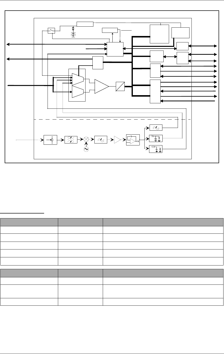
©1999 Navia Aviation AS 21464-5 Detailed Description
USER MANUALNORMARC 7050
MARKER BEACON
12-5
12.1.2.2 Block diagram
Figure 12-2 MO 1374 block diagram
12.1.2.3 Signals
(See block diagram Figure12-2)
TO BACKPLANE::
In From Description
RF_IN Antenna RF from antenna
A_TX1/2[P,N] TX 1373 Analogue input from transmitters
A_PS1/2[P,N] PS 1375 Analogue input from power supplies
A_CI[P,N] CI 1376 Analogue input from Connection Interface
TX1/2_FB TX 1373 Feedback from transmitters
Out To Description
∼RMS_LEV[1:0] RMS Access level
AMUX_A[3:0] TX 1373 PS 1375 Address signals for differential analogue signal
bus
IO_CTRL_BUS TX 1373, CI 1376 Control signals for IOD[7:0]
75MHz
Bandpass
Filter
0.5 MHz
Low pass
Filter
74.5 MHz
Local Oscillator
Mixer
Attenuator Amplifier Modulation detector
Envelope detector
RF-detektor
+
_
Lowpass filter
Keying Envelope
LF-leve l
RF level
+
-
Interrupts
Jumper
CPU
CTRL
port
Double
UART
Analog
MUX
Analog
MUX
CTRL
port
A
D
MO1374
Watchdog 1.
Battery RESET Memory
RAM
EPROM
EEPROM
Real time
clock
RS232
& FSK
drivers
Dual 8:1
CTRL
port
IOD[7:0]
LCD_DATA[7:0]
LC_KEY[7:0]
LC_LED[14:0]
MON_RXD/TXD
CPU SECTION
RF FRONTEND
Diff. amp
KB[7:0]
LC_CTRL_BUS
IO_CTRL_BUS
AMUX_A[3:0]
RF IN
A_XX_[P,N]
Keying Envelope
Battery pwr.
Watchdog 2
RS232
driver
LOCAL_SER_BUS
REM_SER_BUS
RC_SER_BUS
TX_CTRL_BUS
HBK818/1
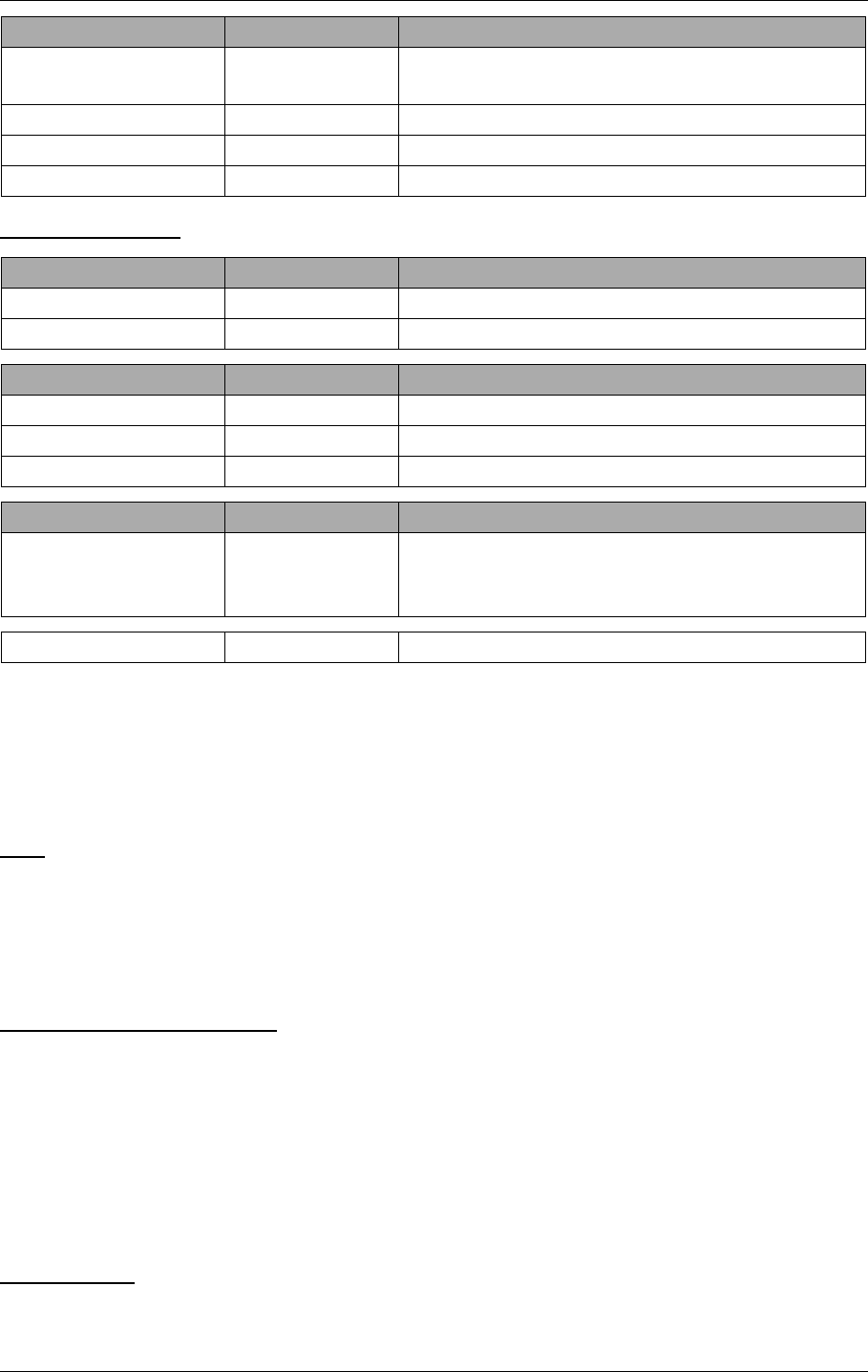
USER MANUAL
12-6
21464-5
NORMARC 7050
MARKER BEACON
Detailed Description ©1999 Navia Aviation AS
TO FRONTPLANE:
12.1.2.4 Building blocks
(See block diagram Figure12-2)
CPU SECTION:
CPU
The CPU is an 80C188EB micro controller. Included in the CPU is an address decoding unit
and two UARTs. Both of these UARTs are used for serial communication. The operating fre-
quency of the CPU is 20MHz. This requires a 40MHz oscillator because of the internal divide
by two circuit.
WATCHDOG AND BATTERY
The watchdogs resets the CPU:
• at power up
• if the CPU does not toggle the watchdog reset bit at less than approx. 1.6 sec. intervals
When the +5V supply voltage goes below the battery voltage, battery voltage is passed
through to the RAM and real time clock. The battery voltage is measured through an optocou-
pler switch in order to keep the battery life time high. The battery lifetime is approximately one
month with continuous use (system power turned off).
INTERRUPTS
4 of the CPU's 5 interrupt lines are utilised for serial communication and AD conversion.
Bidirectional To/From Description
IOD[7:0] TX 1373, CI 1376 Parallel data bus for communication between TX
½, CI and MO1
RC SER BUS Remote Control FSK and RS232 lines to remote control
REM SER BUS Remote PC RS232 line to remote PC
MON_RXD/TXD Other monitor Serial data channel
In From Description
LC_KEY[7:0] LC 1377 Local control panel pushbuttons/switches
KB[7:0] LC 1377 Local keyboard inputs
Out To Description
LCD_DATA[7:0] LC 1377 data bus to LCD
LCD_* LC 1377 Control strobes for LCD_DATA[7:0]
LC_LED[14:0] LC 1377 Led indicators
Bidirectional To/From Description
TX_CTRL_BUS TX 1373 Changeover Control (TX_ADR), transmitter on/
off (TX_ON), card select back (TXCSB), feed
back (TX1/2_FB)
LOCAL SER BUS Local PC RS232 line to local PC

©1999 Navia Aviation AS 21464-5 Detailed Description
USER MANUALNORMARC 7050
MARKER BEACON
12-7
DOUBLE UART
Serial data channel for communication between Monitor 1 and Monitor 2.
RS232 DRIVERS
The RS232 drivers are single supply RS232 drivers. They interface the UARTs to external
PCs and modems.
REAL TIME CLOCK
The real time clock keeps track of the date and time. Date and time is used to timetag monitor
and maintenance data sets. The RTC shall be accurate within 0.5 seconds per 24 hours.
IO BUS
The IO bus is a parallel data bus connecting TX1, TX2 and CI to Monitor 1.
ANALOGUE INTERFACE
Analogue monitor and maintenance parameters are passed to the monitor module via the
analog bus. The analogue bus consists of differential signal lines from the modules TX1, TX2,
PS1, PS2 and CI, and Monitor 1. The TX, PS and CI cards share a common address bus. The
differential signals from the different modules are multiplexed into the monitor module AD sys-
tem.
MEMORY
The memory block contains RAM for data storage, EPROM for the program and EEPROM for
permanent system setup parameters.
RF FRONTEND:
ATTENUATOR
This section consists of three resistive π-attenuators, 6dB, 12dB and 16 dB respectively, all
matched to 50 ohms. Attenuators are selected by strap settings. Nominal input level shall be
adjusted to app. -21 dBm. The section also contains vernier potensiometers within the 6dB
steps. The adjustement range for the potmeters is ±4dB.
BANDPASS FILTER
The section is equipped with a passive bandpass filter to remove input signals outside the MB
channel. Passband: 72-78 MHz
Maximum passband attenuation: 0.2 dB.
MIXER
The 75 MHz RF-signal is mixed down to 500 kHz to simplify the LF-detection. This is done by
the use of a Mini Circuits RMS-2 mixer and a 74.5 MHz local oscillator.
The mixer is specified at max. +1 dBm RF in, and the conversion loss is approximately 7 dB.
Nominal signal levels:
RF in:- 21 dBm 75 MHz AM
LO in: +7 dBm 74.5 MHz sine.
IF out: -28 dBm 500 kHz AM.
LOWPASS FILTER
A passive lowpass filter is then used to remove unwanted mixer products, mainly 149.5 MHz.

USER MANUAL
12-8
21464-5
NORMARC 7050
MARKER BEACON
Detailed Description ©1999 Navia Aviation AS
Stopband: Above 5 MHz
Minimum stopband attenuation: 30 dB.
AMPLIFIER STAGE
The 500 kHz IF signal out of the Mixer section is amplified approximately 20 dB to interface
the LF-detector.
Nominal signal levels:
RF in: - 28 dBm 500 kHz AM.
RF out: - 8 dBm 500 kHz AM.
RF DETECTOR
The LF Detector is realised by the use of a precision peak rectifier consisting of two opera-
tional amplifiers connected in cascade.
Nominal signal levels:
RF in: - 8 dBm 500 kHz AM.
The detected LF signal is then amplified before being split to the three output generating cir-
cuits.
RF LEVEL DETECTOR
The RF level is detected by lowpass filtering the LF signal to remove the ident tone. The low-
pass filter is designed as a two pole active filter using one operational amplifier.
Minimum attenuation in the stopband (400 Hz - 3 kHz):40 dB.
MODULATION LEVEL DETECTOR
The modulation level is detected by a peak detector consisting of an operational amplifier
feeding a diode and a RC-network. The RF level DC is removed before detection. The time
constant of the RC-network is chosen to ensure minimum ripple at the lowest keying fre-
quency. The voltage ripple should be maximum 1% relative to nominal output level.
KEYING ENVELOPE DETECTOR
The keying envelope is detected by the use of an operational amplifier feeding a diode and a
RC network. The RF level DC is removed before detection. The time constant of the RC net-
work is chosen to ensure a significant difference between the dash/dot output level and the
pause level. The output voltage from the peak detector will resemble a pulse train. This pulse
train is then applied to a comparator circuit that converts the output signal to an ideal TTL level
pulse train.
12.1.3 PS1375 Power Supply Module Description
12.1.3.1 General description
PS1375 is a 100W power module with 120V or 230V AC input voltage and +28V/3.5A, +20V/
2.5A, ±12V/1.25A and 5V/6A DC output voltages. The 28V output is temperature compen-
sated to ensure optimum battery charging. All outputs are short circuit protected. PS1375
may operate in parallel with an equal module to increase reliability and power capacity.
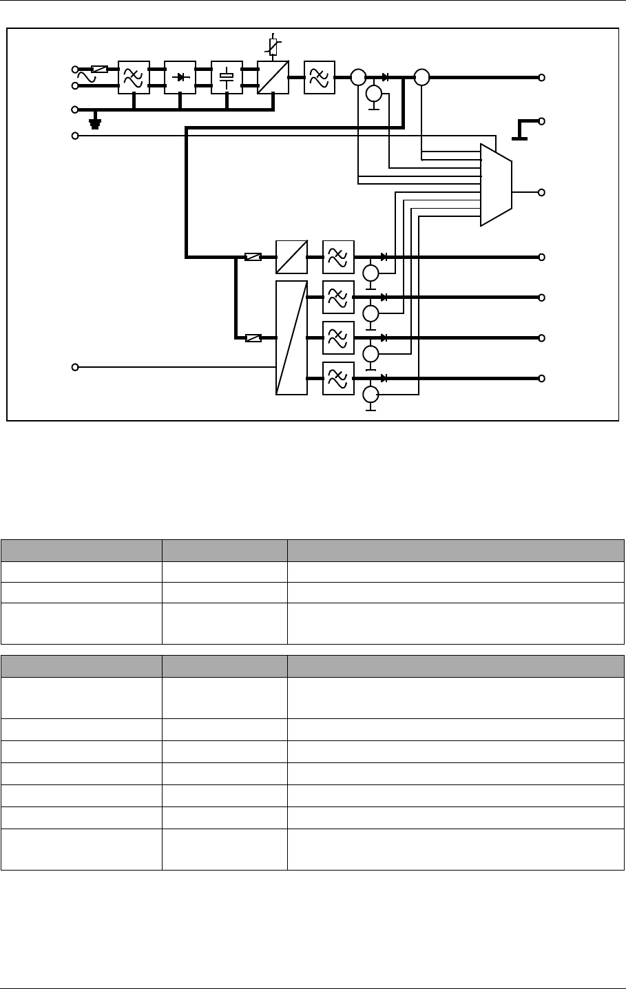
©1999 Navia Aviation AS 21464-5 Detailed Description
USER MANUALNORMARC 7050
MARKER BEACON
12-9
12.1.3.2 Block diagram
Figure 12-3 PS 1375 block diagram.
12.1.3.3 Signals
(See block diagram Figure12-3)
12.1.3.4 Functional description
(See block diagram Figure12-3)
In From Description
VAC[L,N] Manis AC
AC_GND Mains Ground
AMUX_A[2:0] MO 1374 Address signals for differential analogue signal
bus
Out To Description
V28P Battery charger voltage and primary DC voltage
28V
V20P TX 1373 DC voltage to transmitter section 20VDC
V12P System DC voltage +12V
V12N System DC voltage -12V
VDD System voltage to digital parts
A_PS_[P,N] Multiplexed maintenance signals
SYNC Frequency syncronisation between power mod-
ules
DC
DC
DC
DC
DC
V
A A
V
V
V
V
VACL
VACN
ACGND
V20P
V20P_MEAS
V15P
V15P_MEAS
V15N
V15N_MEAS
VDD
VDD_MEAS
IBATT_MEAS
V28P
V28P_MEAS
I28P_MEAS
GND
DC
A
MUX_A[2:0]
A_PS_[P,N]
SYNC
SIGN_IBATT
SIGN_I28P
HBK819/1

USER MANUAL
12-10
21464-5
NORMARC 7050
MARKER BEACON
Detailed Description ©1999 Navia Aviation AS
The mains input is fused and filtered before it is rectified and smoothed. The first DC/DC con-
verter generates 28VDC output which is filtered in the next block. The filter output serves as
both battery charger and input to the +20V, ±12V and +5V DC/DC converters. V28P is tem-
perature compensated to give 26.4V at 50°C, linearly increasing to 29.6V at -30°C.
The voltage (V28P) from either the AC/DC section or the battery is passed through an on/off
switch and separate fuses to the secondary DC/DC converters. Here +20V, ±12V and 5V are
created in one single and one triple output DC/DC converter. All outputs are lowpass filtered
in LC filters.
The or'ing diodes on the DC outputs makes parallel coupling possible. All RMM voltage mea-
surements are done prior to these diodes to make fault tracking possible. All RMM measure-
ments are multiplexed into A_PS_[P,N] by the AMUX_A[2:0] signals.
The RMM measurements are:
12.1.4 CI1376/PB1378 Connection Interface Module Description
12.1.4.1 General description
CI 1376 is the electrical backplane of NM 7050. The module has four functions:
• External connections interface with over voltage protection.
• Motherboard for all plug-in boards.
• Transmitter change over.
• Battery protection against deep discharge
Signal Measurement
I28P_MEAS Total current in V28PP
IBATT_MEAS Battery current in V28P
SIGN_I28P Charge/discharge info to the
SIGN_IBATT current measurements above
V*_MEAS Voltage in corresponding V*
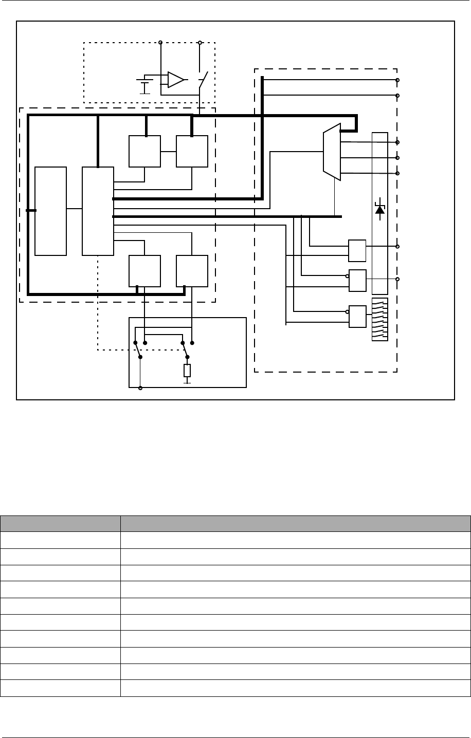
©1999 Navia Aviation AS 21464-5 Detailed Description
USER MANUALNORMARC 7050
MARKER BEACON
12-11
12.1.4.2 Block diagram
Figure 12-4 Connection Interface block diagram
12.1.4.3 Signals
(See block diagram Figure12-4)
For plug in board signals see the specifications for each board..
External Description
REM_* Remote PC RS232 interface
RC_LINE[A,B] Remote control FSK modem interface (serial I/F bus)
RC_[TXD,RXD] Remote control RS232 interface (serial I/F bus)
VAC[P,N] AC voltage input (50-60Hz)
T[OUT,IN]DOOR Temperature sensor input
ANLG[3:1][P,N] Differential analogue DC input
DIGIN[5:0] Digital inputs (TTL level)
DIGOUT[1:0] Digital outputs (TTL level)
V28P +28V DC input in case of external battery charger
V28P_PROT Battery input/output, disconnected if voltage drops below 22V
PS1 PS2
MO2 MO1
TX1 TX2
REM_*
RC_*
VAC[P,N]
T[OUT,IN]DOOR
ANLG[3:1][P,N]
DIGIN[5:0]
AUX_RI_IN[1:0]
DIGOUT[1:0]
AUX_RI_OUT[3:0]
RF_OUT
RF_TX1 RF_TX2
V28P V28P_PROT
Vref
IOD[7:0]
Control bus
A_CI_[P,N]
Serial I/F
Power
G
Q
D
Q
D
Motherboard
Battery Protection
External Connections
Change Over
CI_WR
~CI_RD OE
AMUX_A[3:0]
Dummy load
TX_TO_AIR
Q
D
~CFG_RD OE
Config
Platform
HBK828/1

USER MANUAL
12-12
21464-5
NORMARC 7050
MARKER BEACON
Detailed Description ©1999 Navia Aviation AS
CONTROL SIGNALS:
INTERNAL DATA PATHS
IOD[7:0] RMS databus to and from MO1374
A_CI_[P,N] Differential analogue maintenance signal
to MO1374
V28P,
V20P,
V12[P,N],
VDD" Power" bus from PS1375
12.1.4.4 Building Blocks
(See block diagram Figure12-4)
EXTERNAL CONNECTIONS
CI 1376 contains overvoltage protected interfaces to the following external connections:
• One marker Beacon antenna
• One backup battery (or external battery charger)
• One PC (RS232 direct or via modem)
• One Remote control (via FSK modem or RS232)
• Two temperature sensors
• Three differential analogue DC channels
• One mains voltage sensor (transformer)
• Six digital inputs
• Two digital outputs
In addition, measurement on all power voltages are multiplexed into the analogue mainte-
nance bus. Two auxiliary inputs and four auxiliary outputs are connected to the RMS parallel
bus (IOD). System configuration is transferred from a strap platform to the RMS-system over
the IOD bus.
MOTHERBOARD
Transmitter From Description
RF_TX[1:2] TX 1373 50 ohms RF input
RF_OUT Change over relay 50 ohms RF output
TX_TO_AIR MO 1374 Controls which transmitter is connected to
antenna (change over)
AMUX_A[3:0] Controls which analogue maintenance signal that
is connected to A_CI_[P,N]
CI_WR Controls writing from the IOD bus to
DIGOUT[1:0] external output and
AUX_RI_OUT[3:0] auxiliary remote control
outputs.
~CI_RD Controls reading from DIGIN[5:0] external input
to the IOD bus and AUX_RI_IN[1:0] auxiliary
remote control inputs.
~CFG_RD Controls reading from the system configuration
platform to the IOD bus
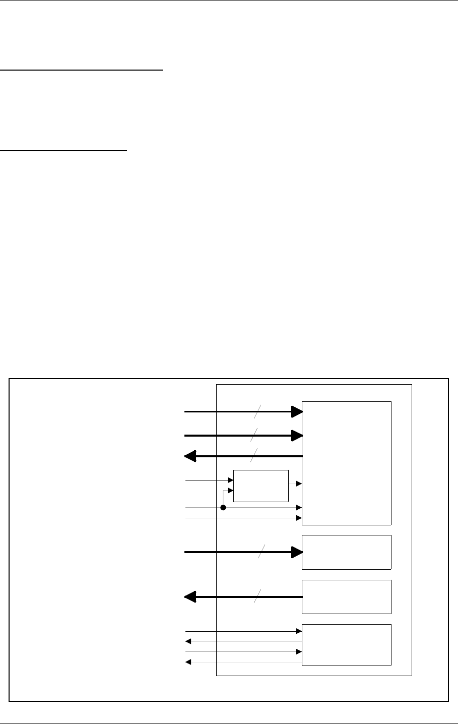
©1999 Navia Aviation AS 21464-5 Detailed Description
USER MANUALNORMARC 7050
MARKER BEACON
12-13
CI1376 performs interconnections between two TX1373 transmitters (TX1 and TX2), two
MO1374 monitors (MO1 and MO2) and two PS1375 power supplies (PS1 and PS2) and the
external connectors.
TRANSMITTER CHANGE OVER
The TX_TO_AIR signal (driven by the station control software in MO1374) controls which
transmitter is connected to the antenna and which is connected to the dummy load. The
change over function is performed by an RF relay and the dummy load is a suitable 50Ω resis-
tor.
BATTERY PROTECTION
A voltage comparator compares the V28P signal (on the PS1375 side) to a reference voltage.
If V28P drops below 22V, the comparator disconnects the battery (V28P_PROT). The battery
is reconnected when V28P exceeds 22V. If external chargers are used (to extend battery
backup time) an external battery protection circuit has to be used and the CI1376 protection
circuit is bypassed.
12.1.5 LC 1377 Local Control and Display/Keyboard Interface
12.1.5.1 General description
LC1377 is an interface card between MO1374 (monitor/TX control w/CPU) and the man/
machine interface (local control pushbuttons/LEDs and LCD/keyboard pushbuttons) of the
Marker Beacon.
12.1.5.2 Block Diagram
Figure 12-5 LC 1377 block diagram
LCD
w/KEYBOARD
LOCAL CONTROL
STATUS LEDs
LOCAL CONTROL
PUSH BUTTONS
AND SWITCHES
RS232
CONNECTOR
TO LOCAL PC
LCD
CONTRAST
ADJUSTMENT
3
8
8
8
15
LC_CTRL_BUS
LCD_DATA[7:0]
KB[7:0]
V12N
VDD
GND
LC_LED[14:0]
LC_KEY[7:0]
LOCAL_TXD
LOCAL_RXD
LOCAL_RTS
LOCAL_CTS
HBK820/1
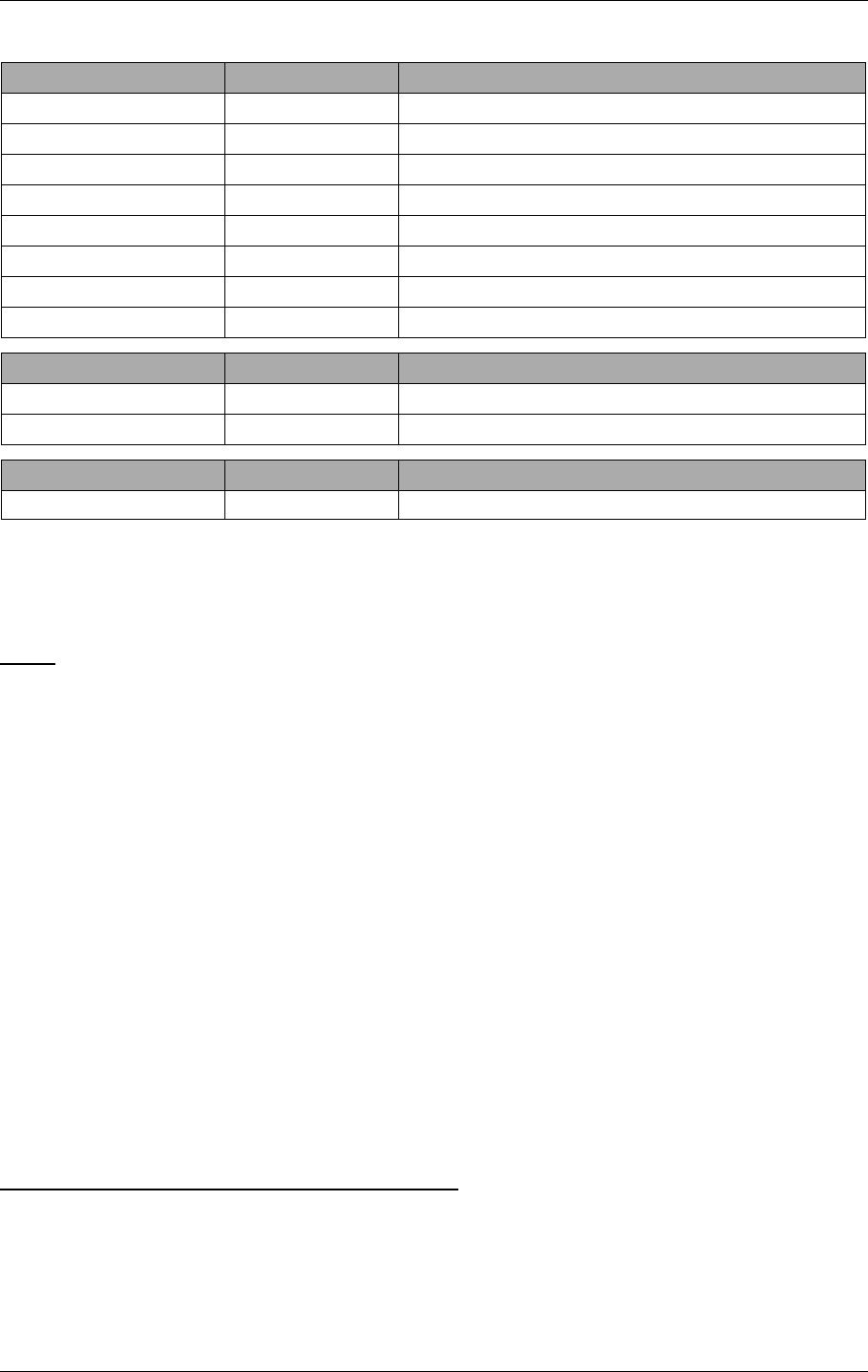
USER MANUAL
12-14
21464-5
NORMARC 7050
MARKER BEACON
Detailed Description ©1999 Navia Aviation AS
12.1.5.3 Signals
12.1.5.4 Building Blocks
(See block diagram Figure12-5)
LEDS
The LEDs on the LC1377 are driven by LED driver input signals. The LED anodes are con-
nected to VDD and the cathodes are connected to LED driver inputs. The LED driver circuits
(outside LC1377) contains the resistors for correct LED illumination currents. LED status indi-
cations includes :
•System Alarm
•System Warning
•System Service
•System Normal
• Main select = TX1
• Main select = TX2
•TX to air = TX1
•TX to air = TX2
• TX1 on/off status
• TX2 on/off status
• Standby TX on air Warning
• Parameter Warning
•Battery Warning
• Monitor disagree Warning
• Maintenance Warning
LOCAL CONTROL PUSHBUTTONS/SWITCHES
The local control pushbutton/switch outputs are normally open. One side of the pushbutton/
switch is connected to ground while the other is connected to the output line. Pushbutton func-
tions include:
• ON/OFF key
• CHANGEOVER key
• MAIN SELECT key
IN From Description
LC_LED[14:0] MO 1374 LED driver inputs
LCD_DATA[7:0] Data input to LCD
LCD_RW LCD R/W select for LCD interface
LCD_RS LCD register select trobe
LCD_ENA LCD enable
V12N -12VDC system voltage
VDD PS 1375 +5 VDC system voltage
GND Ciruit ground
Out To Description
LC_KEY[7:0] MO 1374 Local control push buttons and switches
KB[7:0] MO 1374 Keyboard push buttons
Bidirectional To/From Description
LOCAL_* Local PC RS 232 to local PC

©1999 Navia Aviation AS 21464-5 Detailed Description
USER MANUALNORMARC 7050
MARKER BEACON
12-15
• TX1 ON/OFF key
• TX2 ON/OFF key
• AUTO/MANUAL switch
• REMOTE/LOCAL switch
• WRITE PROTECT switch
LCD KEYBOARD
The LCD keyboard pushbuttons functions in the same way as the local control pushbuttons,
except for the functionality :
• ESCAPE
• NEXT
• PREVIOUS
•ENTER
•PLUS
• MINUS
• QUICK READ
LCD
The LCD is controlled by the LCD_DATA[7:0], LCD_RW, LCD_RS and LCD_ENA. These sig-
nals are directly connected to the LCD.
LCD contrast can be adjusted by means of a potentiometer. Adjust the potentiometer until the
LCD can be read clearly. The adjustable voltage is between -8.5V and +5V.
RS232 TO LOCAL PC
The RS232 interface to the local PC includes TxD, RxD, RTS and CTS. The RS232 lines has
over voltage protection.
12.2 Tower Equipment
12.2.1 Remote Control Assembly
12.2.1.1 General Description
The RCA1240A remote control assembly consists of the remote control RC1241A and front
panel RF1242A, and provides the user interface to the MB from the control tower, or technical
equipment room. The RCA1240A connects to the MB either by using ordinary telephone lines,
or by an optional transmission medium using the RS232 signals. The selection between these
two interfaces are done by means of straps on the RC1241A.
The line interface is using the V.21 standard (300 baud FSK) for use with ordinary 2-wire 600
ohm telephone line. The transmitter level is -10 dBm, and the receivers dynamic range is from
-10 dBm to -34 dBm.
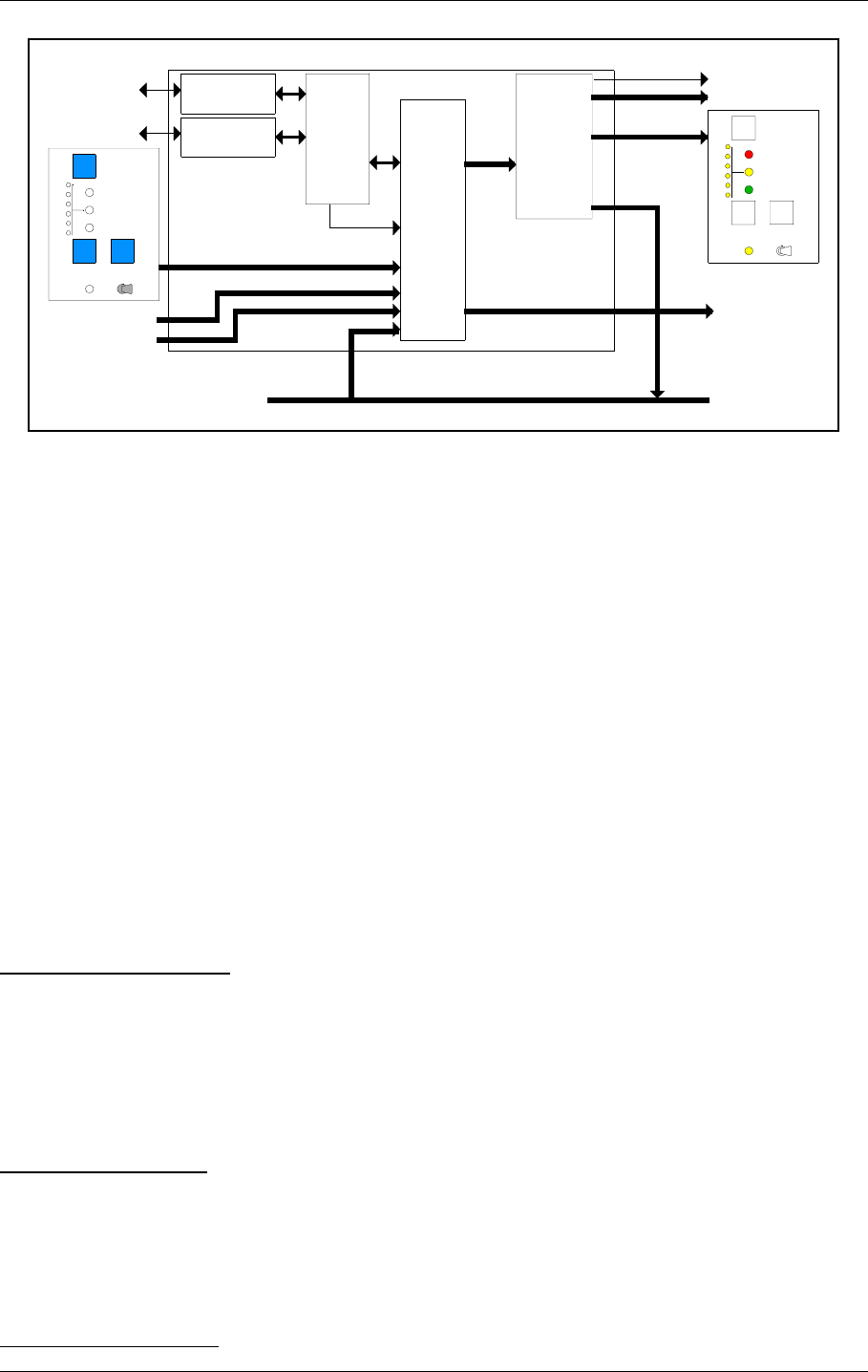
USER MANUAL
12-16
21464-5
NORMARC 7050
MARKER BEACON
Detailed Description ©1999 Navia Aviation AS
12.2.1.2 Block Diagram
Figure 12-6 RCA1240A block diagram.
12.2.1.3 Signals
CONTROL INPUTS: MB control signals. Consists of INTER-
LOCK and TX_OFF.
OPTO OUTPUTS: Optocoupler outputs. Collector/emitter
for ALARM, NORMAL, WARNING and
STB_ALARM.
SLAVE_DIRECT_BUS: Data interface to optional slave panel.
Consists of open collector outputs
(ALARM, NORMAL, WARNING,
STB_ALARM and SLAVE_BUZZER)
and active low inputs (ON_OFF,
CHANGEOVER and SILENCE). If this
slave interface is used, connection of
SLAVE_SERIAL_BUS is unnecessary.
12.2.1.4 Block Description
CONTROL AND UARTS
This unit interprets serial data from the MB and generates status outputs to front panel LEDs,
slave panel outputs, opto outputs and buzzers based on the received status. Failure in data
from MB results in alarm condition. Remote control front panel operations/slave panel opera-
tions are sent together with other control signals to the MB after being converted to serial
data. Serial communication with an optional slave panel is continuously updated.
INTERFACE SELECT
This strap field selects between line interface or RS232 interface. The line interface is used for
standard connection between MB and remote control using telephone lines, while the RS232
interface should be used when another transmission medium is used (must interface to the
RS232 signals). The default is line interface.
LINE DRIVER/MODEM
Line
driver/modem
Telephone
line
Control
and
uarts
LED OUTPUTS
RC1241A
RS232
driver
RS232 Signal
drivers
SLAVE DIRECT BUS
RF1242A/B
Front panel
LEDs
AUX_IN
AUX_OUT
KEYBOARD INPUTS
RF1242A/B
Keys and
switches
CONTROL INPUTS
SLAVE DIRECT
INPUTS
SLAVE
LED
OUTPUTS
OPTO OUTPUTS
Interface
select
&
config
RST_RC_AURAL_ONLY
STATUS
ALARM
HBK821-1
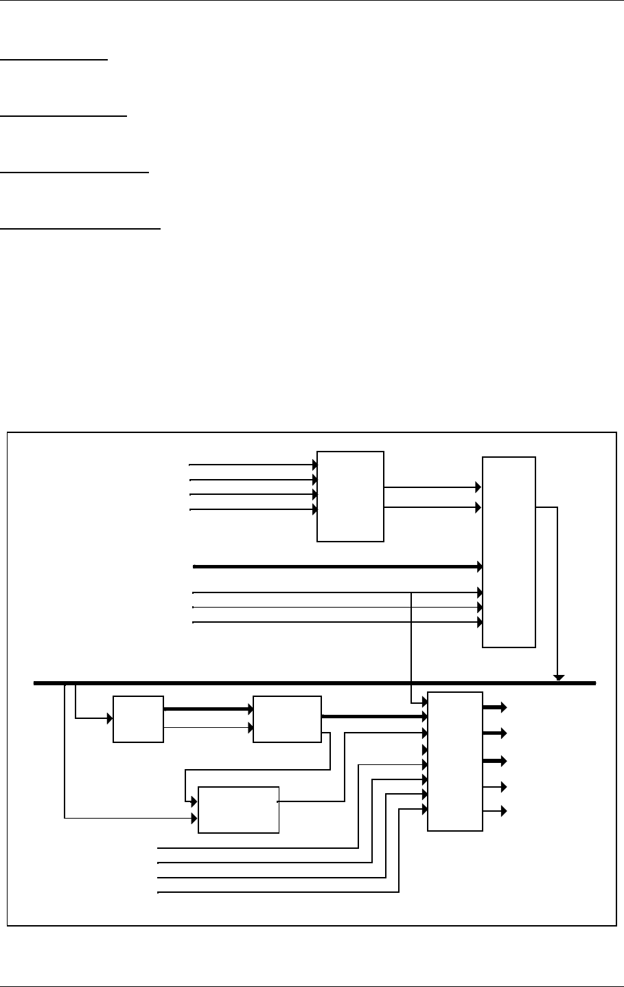
©1999 Navia Aviation AS 21464-5 Detailed Description
USER MANUALNORMARC 7050
MARKER BEACON
12-17
This unit converts logic level serial signals to and from FSK line signals.
RS232 DRIVER
This unit converts logic level serial signals to and from RS232 signals.
SIGNAL DRIVERS
This unit drives the front panel LEDs, opto outputs and slave panel LEDs.
FRONT PANEL LEDS
This unit contains the front panel LEDs used to indicate the state of the MB.
KEYS AND SWITCHES
This unit contains the keys and switches used to interface to the operator.
NMP114A Remote Control
12.2.1.5 General Description
NMP114A is a FPGA containg the remote control function. The NMP114A sends data from
remote control and receives data from the transmitter control TCA1218A/B. NMP114A is
based on the Actel ACT1020 FPGA. For electrical specifications see the ACT1020 datasheet.
12.2.1.6 Block Diagram
Figure 12-7 NMP114A block diagram.
RX
uart
SERIAL
DATA
IN
New message
timer
Message
detector
LED
&
buzzer
filter
CHANGEOVER_KEY
TX
uart SERIAL
DATA
OUT
AUX_IN
RC_BUS
PARITY ERROR
MESSAGE DATA LED OUTPUTS
NEW MESSAGE
MESSAGE
TIMEOUT
MESSAGE DATA
CARRIER
DETECT SLAVE LEDS
ON_OFF_KEY
SLAVE_ON_OFF_KEY
SLAVE_CHANGEOVER_KEY
Command
mixer
ON_OFF
CHANGEOVER
INTERLOCK
ACCESS_GRANT_SWITCH
TX_OFF
AUX_OUT
ALARM BUZZER
SLAVE BUZZER
SILENCE_KEY
SLAVE_SILENCE_KEY
RST_RC_AURAL_ONLY
RST_SL_AURAL_ONLY
HBK822/2

USER MANUAL
12-18
21464-5
NORMARC 7050
MARKER BEACON
Detailed Description ©1999 Navia Aviation AS
12.2.1.7 Block Description
COMMAND MIXER
This unit mixes the on/off and changeover commands from the different sources (remote con-
trol front panel or slave front panel direct input).
TX UART
Converts parallel data to 2-bytes serial messages. The protocol is start bit, 8 data bits, 1 stop
bit, odd parity.
RX UART
Converts serial data from remote control to parallel data (2 bytes).
MESSAGE DETECTOR
Messages are accepted only if two equal messages are received in sequence. If so, the data
output is updated and a new-message pulse is asserted.
NEW MESSAGE TIMER
Checks that an OK message and carrier detect is present. Missing message or no carrier
detect for 2 seconds or more gives timeout.
LED & BUZZER FILTER
Data from the MB is filtered according to the following descriptions:
• Missing data from MB sets an alarm condition.
• Activating SILENCE-key turns on all LED’s (lamptest).
• Interlock turns off all LEDs.
Buzzers are activated at transitions from normal to alarm. Lamptest always activates buzzers.
Pressing SILENCE-key deactivates the local buzzer. The remote control SILCENCE-key may
deactivate the slave panel buzzer (configurable).
12.2.2 Remote Frame Assembly - RFA1353
GENERAL DESCRIPTION
The RFA1353 remote frame assembly is a subrack which can fit a maximum of five
RCA1240A remote control assemblies. The remote frame assembly is 19’’ wide and three
units high. It contains a power supply PS635B, a motherboard MB1347A and one mother-
board MB1346A for each RCA1240A.
Power to the remote frame assembly is supplied via connector P2 on MB1347 (GND on pin1,
24V on pin3). Power to each remote control is supplied from connector P3 on MB1347A.
The power supply PS635B is connected to MB1347A. PS 635B is built around a switch-mode
DC/DC converter module (Eripower PKA 2212). The unit features shutdown for low input volt-
age, and current limiting on outputs ( short circuit proof). Inputs are protected by fuses.
MB 1346A is a motherboard for RCA 1240A/B. It has the following connectors:
J1 Backplane connector for RCA1240
J2 RS-232 connector for use with external
line modems, radio modems or fibre
optic connections (alternative to P9 line
connection).
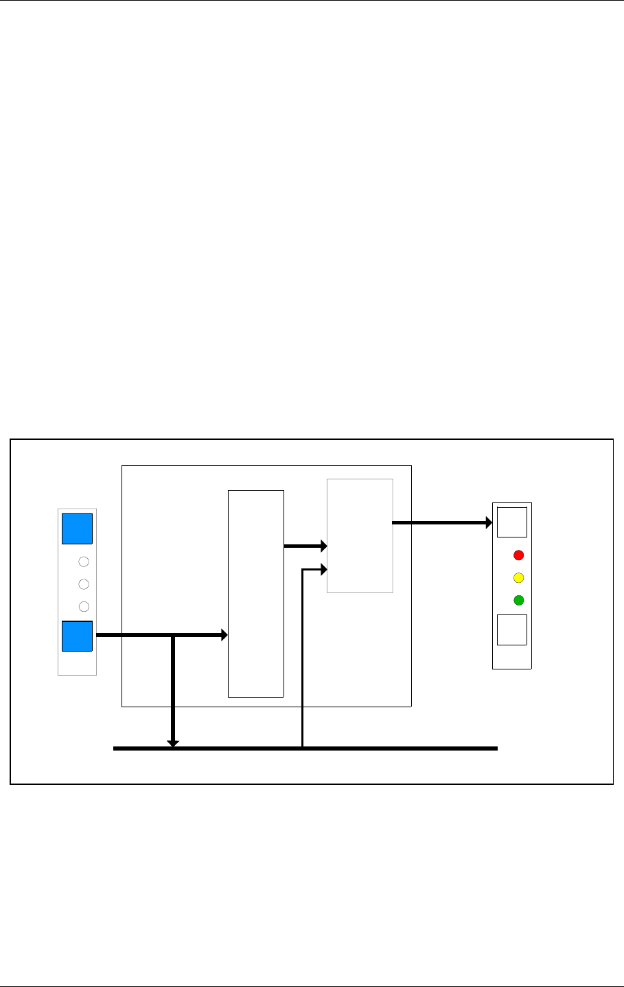
©1999 Navia Aviation AS 21464-5 Detailed Description
USER MANUALNORMARC 7050
MARKER BEACON
12-19
P3 Parallel connection to slave panel or sta-
tus unit.
P4,P5 Power connectors
P6 Aux in/out signals. May be used for FFM
status, intruder alarm or other auxiliary
functions
P7 Opto coupler outputs for ALARM, NOR-
MAL, WARNING and STB. ALARM.
P8 Interlock connector (alternative connec-
tor on slave panel)
P9 RC telephone line. Alarm output and off
input to establish automatic shutdown of
GP when LLZ is off.
12.2.3 SF1344 / SP 1394 Remote Slave Panel
12.2.3.1 General Description
The SF1344A / SP 1394A are slave panel user interfaces to the MB from the control tower, or
technical equipment room. The units connects to the remote control by directly connecting to
the driver circuits on the remote control. SF 1344A and SP 1394A are very similar except for
mechanical dimensions.
12.2.3.2 Block Diagram
Figure 12-8 SF1344A / SP 1394A block diagram.
12.2.3.3 Signals
SLAVE_DIRECT_BUS: Data interface from remote control to
slave panels. Consists of open collector
outputs (ALARM, NORMAL, WARNING,
STB_ALARM (for hot standby configura-
tions) and SLAVE_BUZZER) and active
Control
and
uarts
LED OUTPUTS
SF1344A
Signal
drivers
SLAVE DIRECT BUS
LEDs
KEYBOARD INPUTS
Keys
SLAVE DIRECT
INPUTS
SLAVE
LED
OUTPUTS
STATUS
Printed Circuit Board
HBK823-1
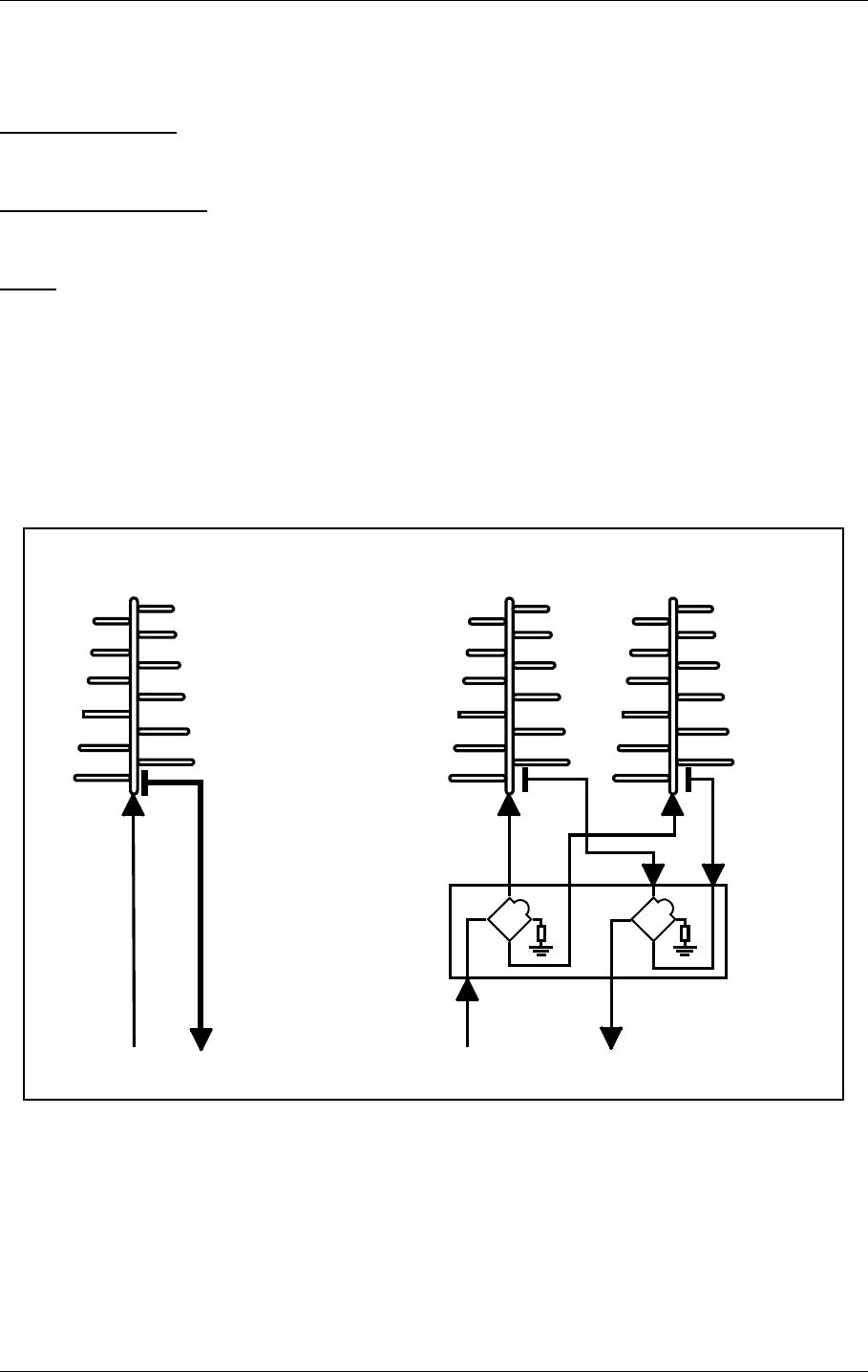
USER MANUAL
12-20
21464-5
NORMARC 7050
MARKER BEACON
Detailed Description ©1999 Navia Aviation AS
low inputs (ON_OFF and SILENCE).
12.2.3.4 Block Description
SIGNAL DRIVERS
This unit drives the front panel LEDs.
FRONT PANEL LEDS
This unit contains the front panel LEDs used to indicate the state of the MB.
KEYS
This unit contains the keys used to interface to the operator.
12.3 Antenna
Normarc supplies single and dual antennas, NM 3561 and NM 3562 respectively. The single
antenna may be used for inner, middle and outer marker, while the dual antenna is specially
designed for outer markers. The advantage of the dual antenna is a lower spread in FLYING
THROUGH TIME inside the localizer coverage area. In addition to two antenna elements, the
monitor and distribution network DI 726 is included in NM 3562.
Figure 12-9 Antenna block diagram
Figure12-10 shows the field strength of the radiated signal directly above the middle marker
antenna. Figure12-11 and Figure12-12 illustrate the field strength above the outer marker
antenna, using single and dual antenna, respectively. The localizer course sector is scetched.
Along an elliptical curve, the field strength is constant. If you look at the diagrams as ordinary
geographical maps, you will see that the dual antenna "field-strength-mountain" is steaper
and more stretched sideways than the single antenna "mountain". This corresponds to a
sharper on/off response on the aircraft's marker beacon instruments.
SINGLE ANTENNA SYSTEM
NETWORK
DI 726
RF OUT RF IN
DUAL ANTENNA SYSTEM
RF OUT RF IN
5050
HBK914-1
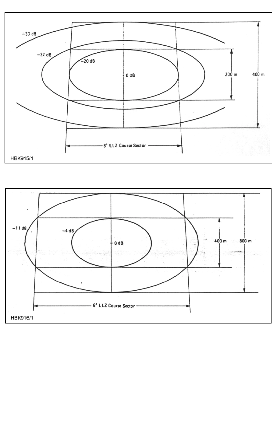


©1999 Navia Aviation AS 21464-5 Circuit diagrams
USER MANUALNORMARC 7050
MARKER BEACON
13-1
13 Circuit diagrams
Circuit Diagrams for NM 7050
Main Cabinet
• TX 1373
• MO 1374
• PS 1375
• CI 1376
• LC 1377
• PB 1378
Tower Equipment
• CA 1240:
• RC 1241
• RF 1242
• RFA 1353:
• MB 1346
• MB 1347
• PS 635
• SF 1344
• SP 1394
Extension Board
• EB 1384


©1999 Navia Aviation AS 21464-5 Parts lists
USER MANUALNORMARC 7050
MARKER BEACON
14-1
14 Parts lists
Electrical Parts List for NM 7050
Main Cabinet
• TX 1373
• MO 1374
• PS 1375
• CI 1376
• LC 1377
• PB 1378
Tower Equipment
• CA 1240:
• RC 1241
• RF 1242
• RFA 1353:
• MB 1346
• MB 1347
• PS 635
• SF 1344
• SP 1394
Extension Board
• EB 1384


©1999 Navia Aviation AS 21464-5 Component Locations
USER MANUALNORMARC 7050
MARKER BEACON
15-1
15 Component Locations
Component Location for NM 7050
Main Cabinet
• TX 1373
• MO 1374
• PS 1375
• CI 1376
• LC 1377
• PB 1378
Tower Equipment
• CA 1240:
• RC 1241
• RF 1242
• RFA 1353:
• MB 1346
• MB 1347
• PS 635
• SF 1344
• SP 1394
Extension Board
• EB 1384


©1999 Navia Aviation AS 21464-5 ANTENNA TYPE NM 3561 / NM
USER MANUALNORMARC 7050
MARKER BEACON
A-1
PART V APPENDIX
A ANTENNA TYPE NM 3561 / NM 3562
A.1 Antenna NM 3561 / NM 3562 For Ils Marker Beacon
The NM 3561/NM 3562 Marker Beacon Antennas are log-periodic dipoles possessing proper-
ties of high gain and directivity, and low side lobes. The performances og the antennas con-
form to ICAO Annex 10 item 3.1.6, and are such that they are largely independent of
environment factors such as rain, snow and ice, and they can therefore be located at «diffi-
cult» sites. The directivity of the antennas can, if required, be even further increased by add-
ing additional elements to the array.
The radiation patterns for the antennas are almost unaffected by the surrondings, and the
antennas are therefore suitable for offset location where tilting of the antennas is necessary in
order to obtain the required signal coverage. (Refer to figure A-1)
Figure 12-10, 12-11 and 12-12 shows constant field strenght lines through points in the glide
path (GP angle 3º). The marker beacons are located vertically beneath the localizer course
line at distance of 1050 m (middle marker) and 3.9 nautical miles (outer marker) from the
threshold. The field strengths specified are relative to the maximum level directly above the
antenna. The figures show that for an aircraft travelling at a speed of 50 m/s (96 knots) within
the maximum allowable course sector of 6º the duration of the visual indication will be within
the prescribes limits. The instrument panel lamp should be adjusted so as to switch on or off
at the levels indicated in the figures i.e. -27 dB to -33 dB for Figure 12-10, -11 dB to Figure 12-
11, and -13 dB to -25 dB for Figure 12-12.
The marker beacon antennas are mounted on poles, with the dipoles parallel to the course
line. The rear end of an antenna should be at least 2 metres above the ground.
The NM 3562 antenna comprises two elements, and is fed via a distribution network (DIA 726)
which splits the transmitter power into two equal parts. The network is a coaxial cable hybrid
housed in silumine box together with the monitor network which is used to combine the signal
from the two monitor probes.

USER MANUAL
A-2
21464-5
NORMARC 7050
MARKER BEACON
ANTENNA TYPE NM 3561 / NM ©1999 Navia Aviation AS
Specifications: NM 3561: NM 3562:
Antenna construction 1 LPDA 2 LPDAs
Frequency 75 MHz 75 MHz
Gain 8,2 dB 11 dB
VSWR 50 Ohm 1,2 dB 1,2 dB
Required RF power 0,5W 0,4W
Dimensions 3,3 x 2,2 m 3,3 x 4,7 m
Weight 50 kg 110 kg
Mounting Both types: 2.2 metres above ground
Temperature Both types: -40ºC to +70ºC
Wind velocity Both types: up to 180 km/h

©1999 Navia Aviation AS 21464-5 MAINTENANCE PARAMETERS
USER MANUALNORMARC 7050
MARKER BEACON
B-1
B MAINTENANCE PARAMETERS
BOARD PARAMETER NAME FUNCTION
NAME
PA CURRENT Power Amplifier Supply Current (20V)
VOLTAGE 20V Power Amplifier Supply Voltage (20V)
RF LEVEL DETECTED Detected RF level voltage
RF LEVEL DAC RF level control voltage from D/A converter
TX1 / TX2 CARRIER POWER Computed carrier Output Power
TX1373A MODULATION DEPTH Modulation Depth
VOLTAGE 5V +5V supply voltage
VOLTAGE 12V +12V supply voltage
VOLTAGE -12V -12V supply voltage
KEY_GATE Keying envelope (toggling)
MO1 / MO2
MO1374A BATTERY RAM backup battery voltage (3.3V)
VOLTAGE 28V +28V supply voltage prior to OR diode
VOLTAGE 20V +20V supply voltage prior to OR diode
PS1 / PS2 VOLTAGE 5V +5V supply voltage prior to OR diode
PS1375A VOLTAGE 12V +12V supply voltage prior to OR diode
VOLTAGE -12V -12V supply voltage prior to OR diode
CURRENT 28V +28V supply current
CURRENT BATTERY Battery current
Voltage 28V +28V supply voltage
Voltage 20V +20V supply voltage
CI Voltage 12V +5V supply voltage
CI1376A Voltage 5V +12V supply voltage
Voltage -12V -12V supply voltage
TEMP OUTDOOR Temperature outdoor
TEMP INDOOR Temperature indoor
VOLTAGE AC Mains voltage (via transformer)
ANALOGUE 1
ANALOGUE 2 User defined differential
ANALOGUE 3 Analog input 1-3
USER IO DIGITAL 1
CI1376A DIGITAL 2
DIGITAL 3 User defined digital
DIGITAL 4 input 1-6
DIGITAL 5
DIGITAL 6


©1999 Navia Aviation AS 21464-5 CUSTOMERS INFORMATION
USER MANUALNORMARC 7050
MARKER BEACON
C-3
WHAT’S YOUR OPINION?
We here in Navia Aviation want to do our utmost to meet the expectations and needs of the
most important people in the world to us - you, our customers.
We will be in contact now and again to make sure you are still satisfied with our products and
our service.
But, please don’t wait for us! Any time you might have a complaint (or compliment) or sugges-
tions as to how we could serve you better, we would appreciate receiving your comments on
the enclosed form - be it about our delivery, product specifications, operation, maintenance,
service, or our performance in general.
We take your opinions seriously, and will confirm receipt of your comments and keep you
advised of any resulting actions.
Yours Sincerely,
Linda Røssland
Customer Service


©1999 Navia Aviation AS 21464-5 CUSTOMERS INFORMATION
USER MANUALNORMARC 7050
MARKER BEACON
C-5
Product Report Please forward to:
Customer Service Dept. CS - No.:
Customer / company: Name: Received by: Date:
Address: Phone: Fax number: E-mail:
Site of installation: Contract number: Navia order No.: Warranty expires:
Product: Serial No:
Fault description / symptoms: Attachement:


©1999 Navia Aviation AS 21464-5 CUSTOMERS INFORMATION
USER MANUALNORMARC 7050
MARKER BEACON
C-7
Customer
Notification of Goods in Transit
Customer’s Engineers to:
Form to be faxed prior to shipment to NAVIA AVIATION AS, Customer Service Dep.
(Fax No. . +47 23 18 02 13)
Sender’s Name:................................................... Tel: .......................................................
Site: ..................................................... Fax: ......................................................
Return Adress:.......................................................................................................................
Consignee:
NAVIA AVIATION AS
P.O. Box 50, Manglerud
N-0612 Oslo Tel: +47 23 18 02 00
NORWAY. Fax: +47 23 18 02 13
Carrier’s Name: ..................................................... Date of Shipment: .............................
Carrier’s Ref No: ................................................... Number of Packages: .............................
The following item(s) will be sent for repair under Maintenance Contract No.
____________
Item Description Quantity Part Number Serial Number
1
2
3
4
5
NAVIA AVIATION AS:
Please fax acknowledgement of goods received (including date received) to:
__________________
