Leidos NORMARC7033 7033 Dual Frequency Glide Path User Manual
Lockheed Martin Air Traffic Management 7033 Dual Frequency Glide Path
Leidos >
Contents
- 1. Normarc 7033 Instrument Landing System Operating Manual
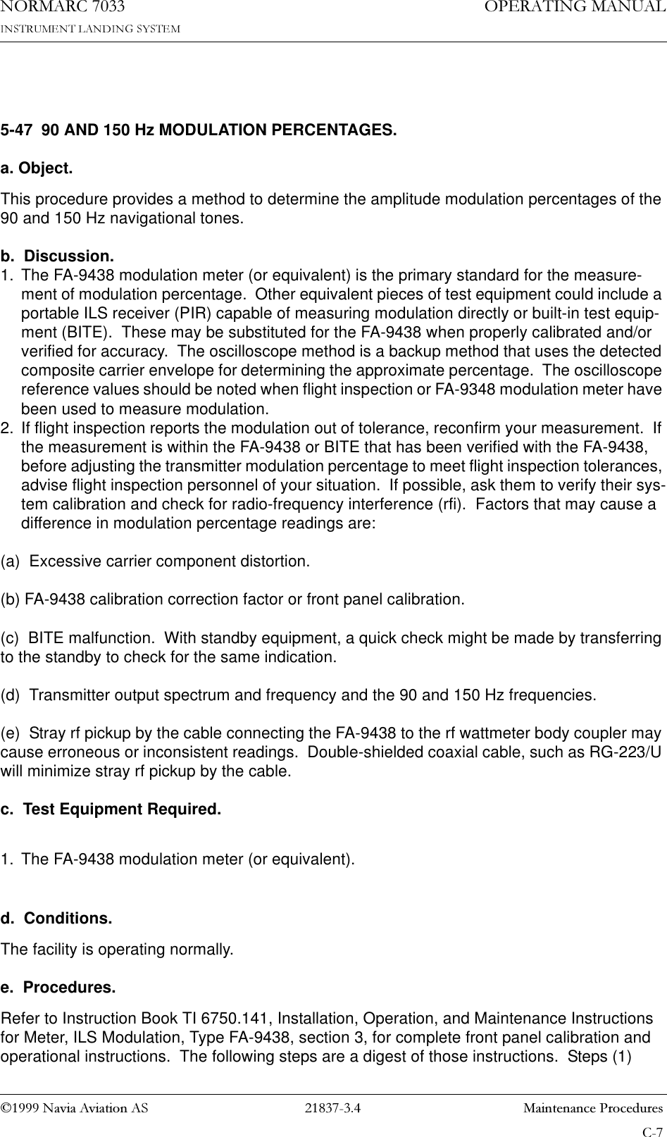
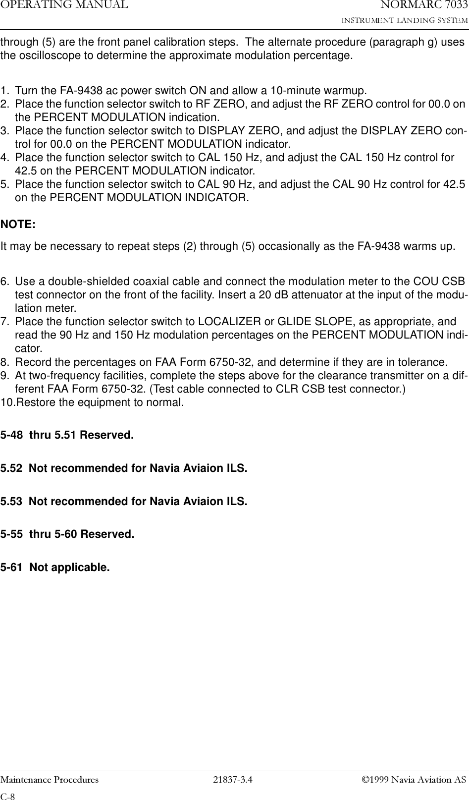
- 2. Normarc 7033 ILS Technical Handbook
- 3. Normarc ILS Installation and Commissioning Hanbook Vol 1
- 4. Normarc ILS Installation and Commissioning Hanbook Vol 2
- 5. Normarc ILS Installation and Commissioning Hanbook Vol 1 and 2
- 6. Normarc ILS General Description
- 7. Normarc 7033 Instrument Landing System Operation Manual
- 8. Normarc ILS Installation and Commissioning Handbook Vol 1
- 9. Normarc ILS Installation and Commissioning Handbook Vol 2
- 10. Normarc ILS Installation and Commissioning Handbook Vol 1 and 2
- 11. Normarc 7033 ILS General Description
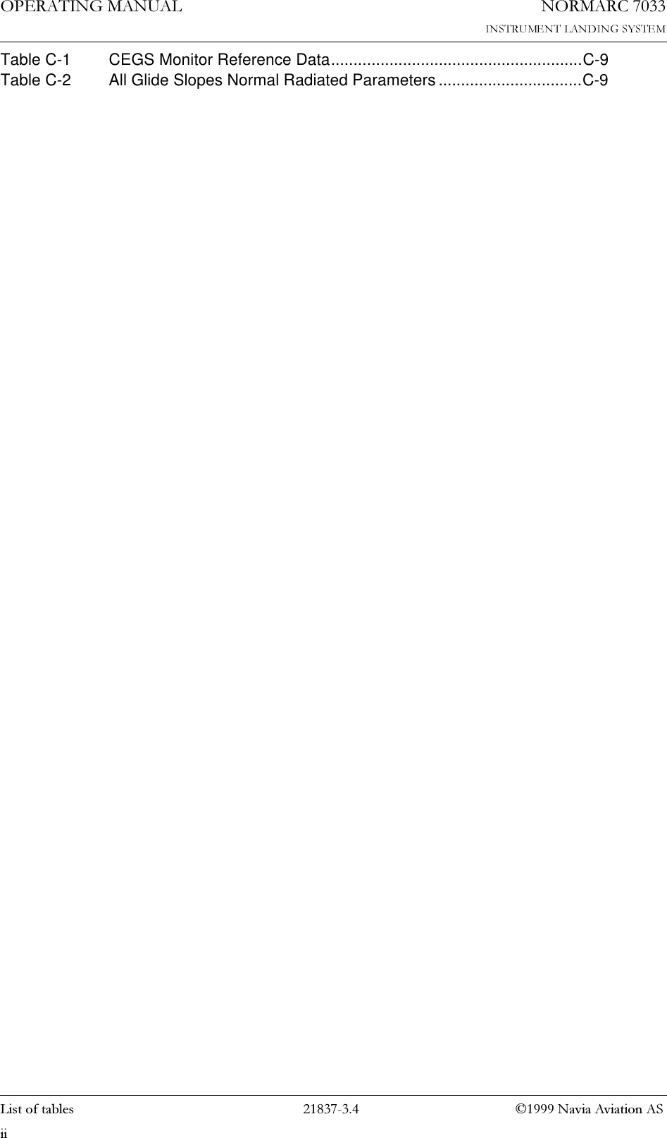
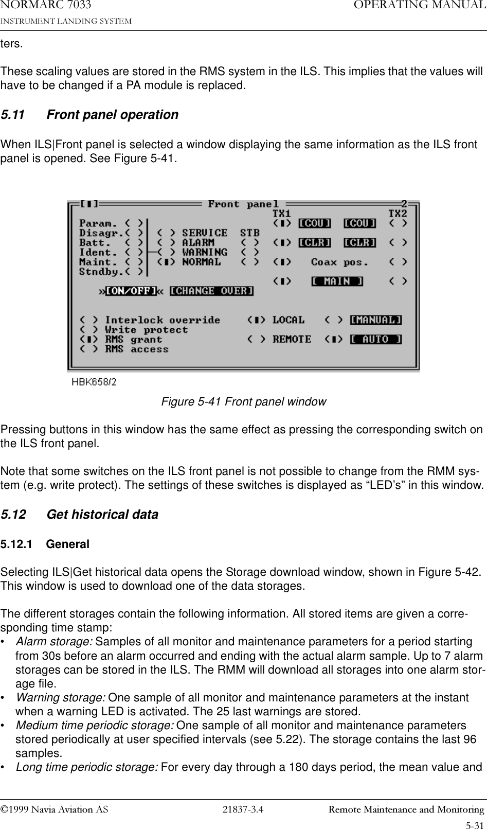
Normarc 7033 Instrument Landing System Operating Manual

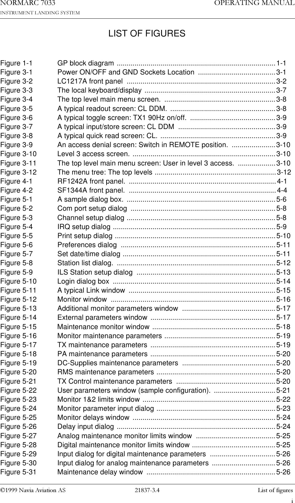
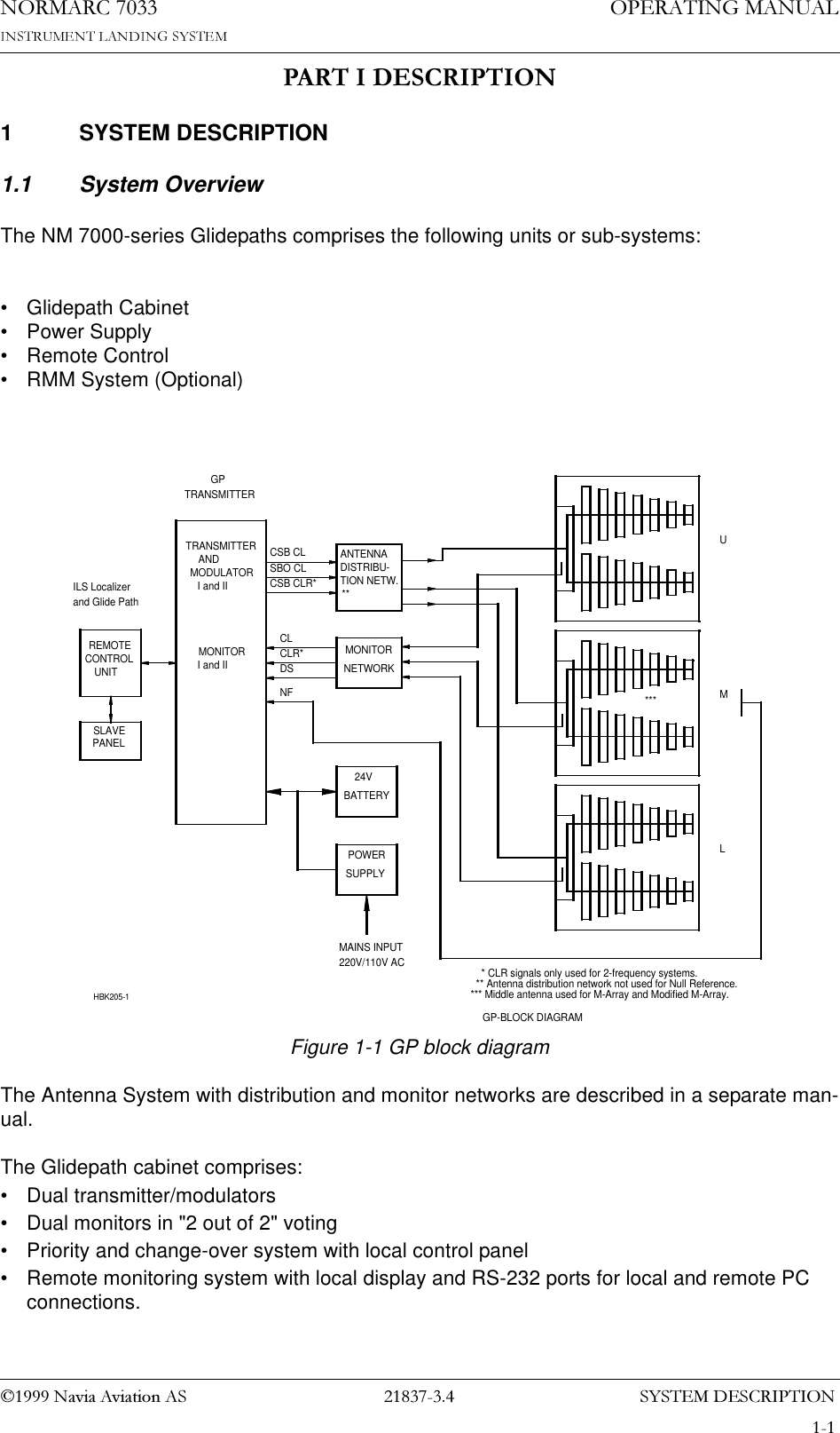

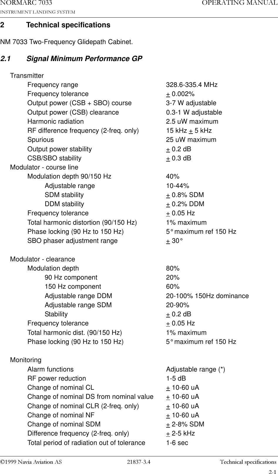

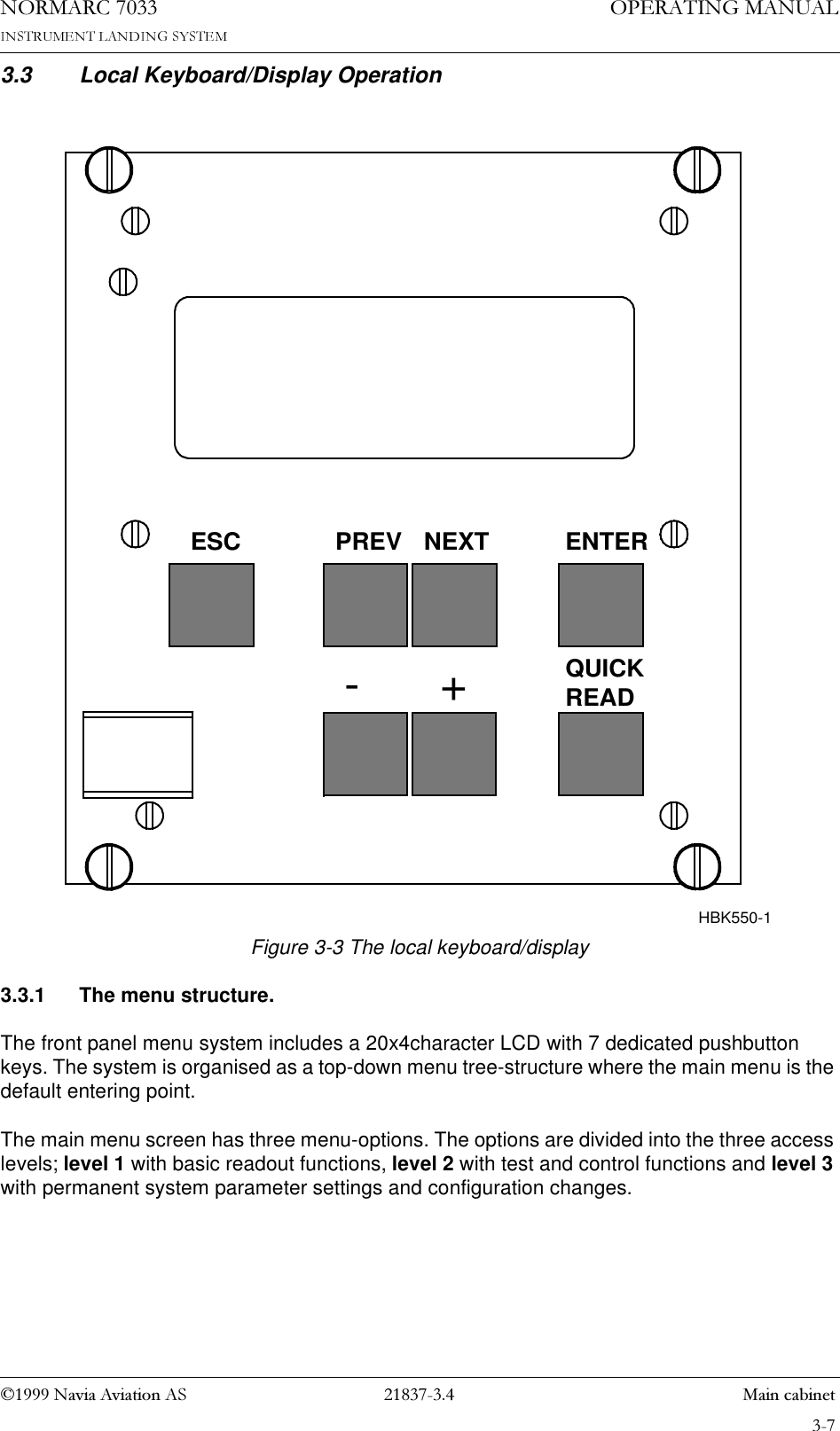
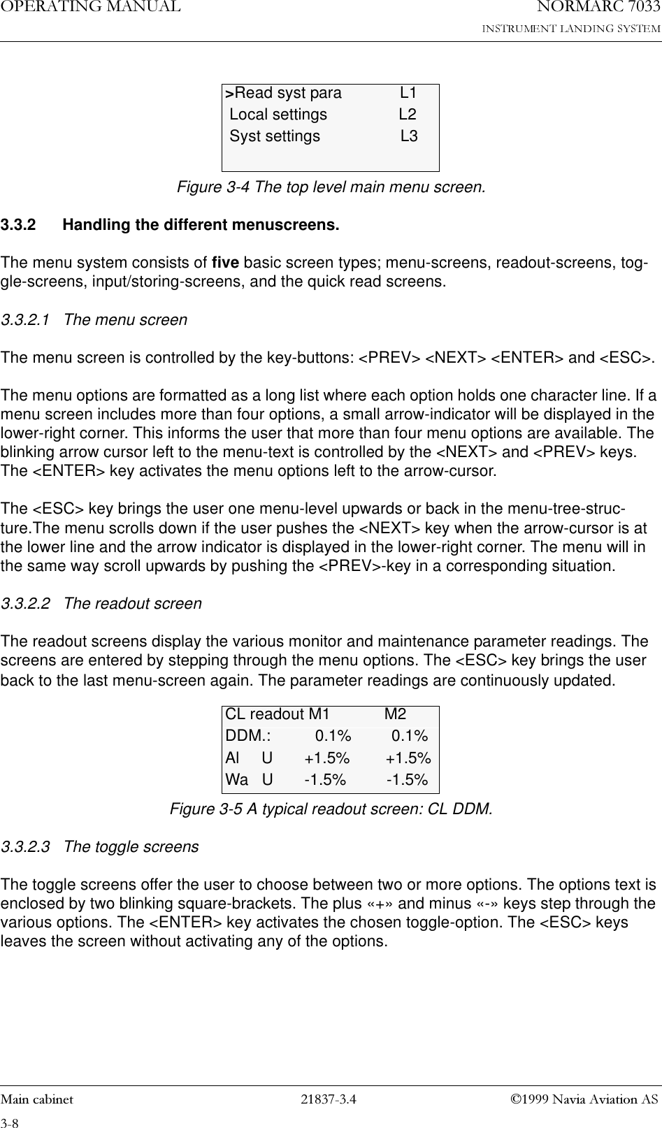
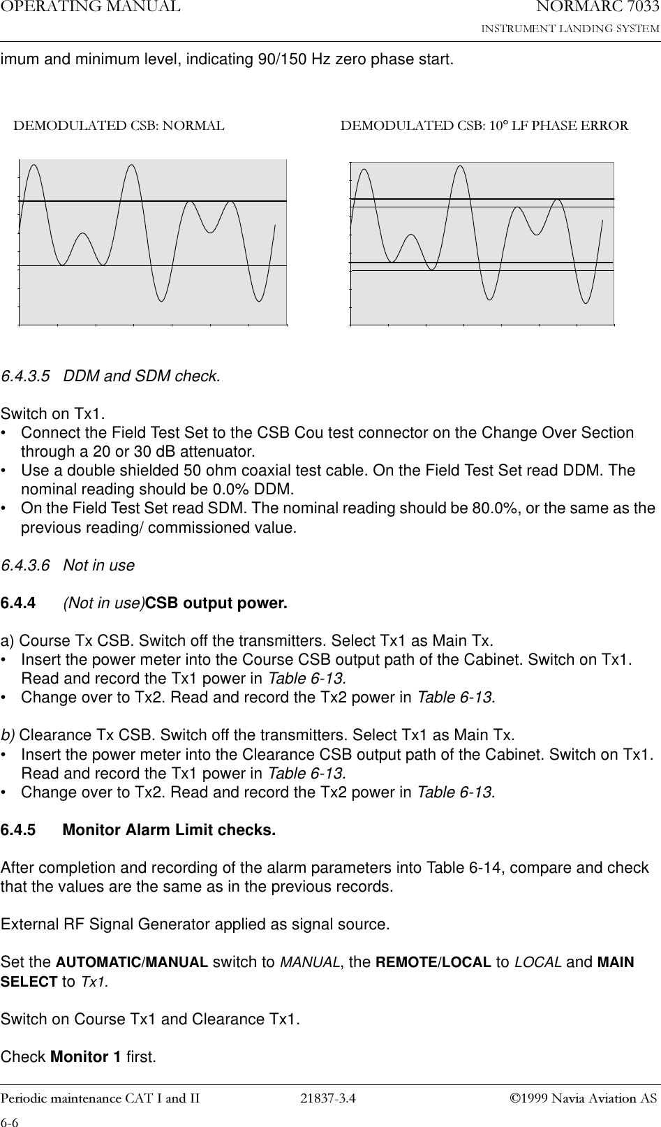
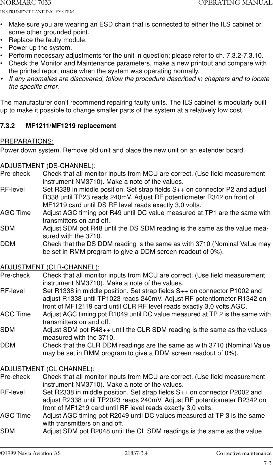
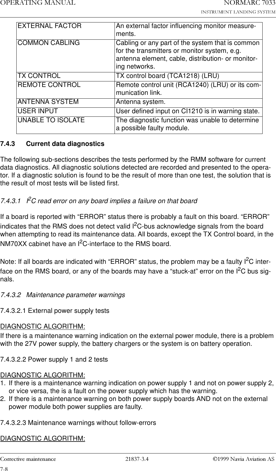
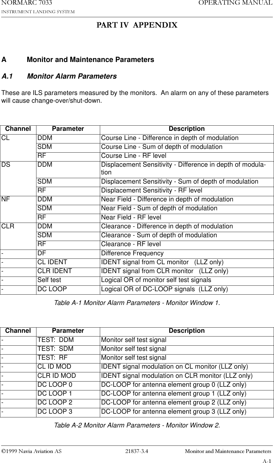
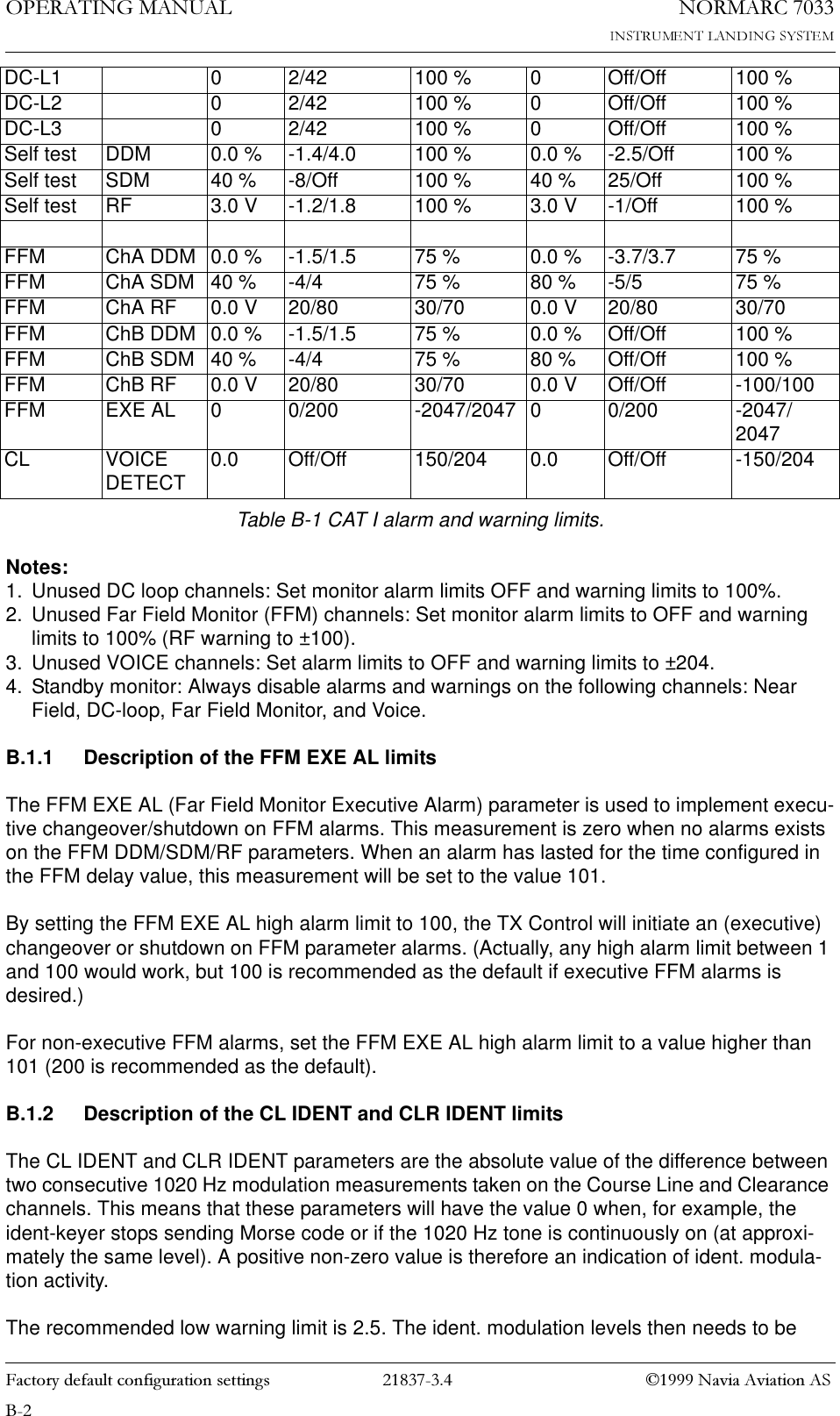
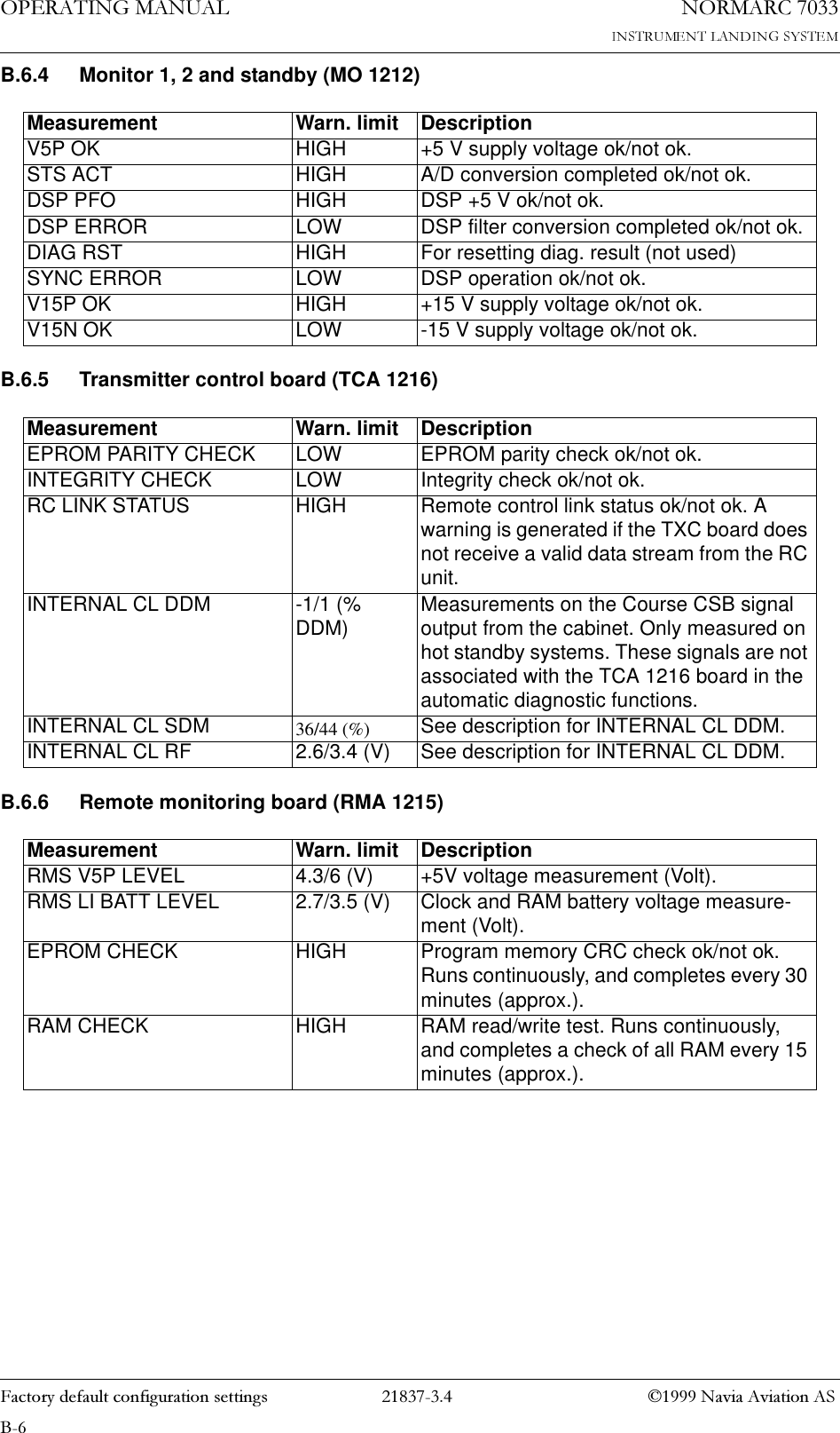
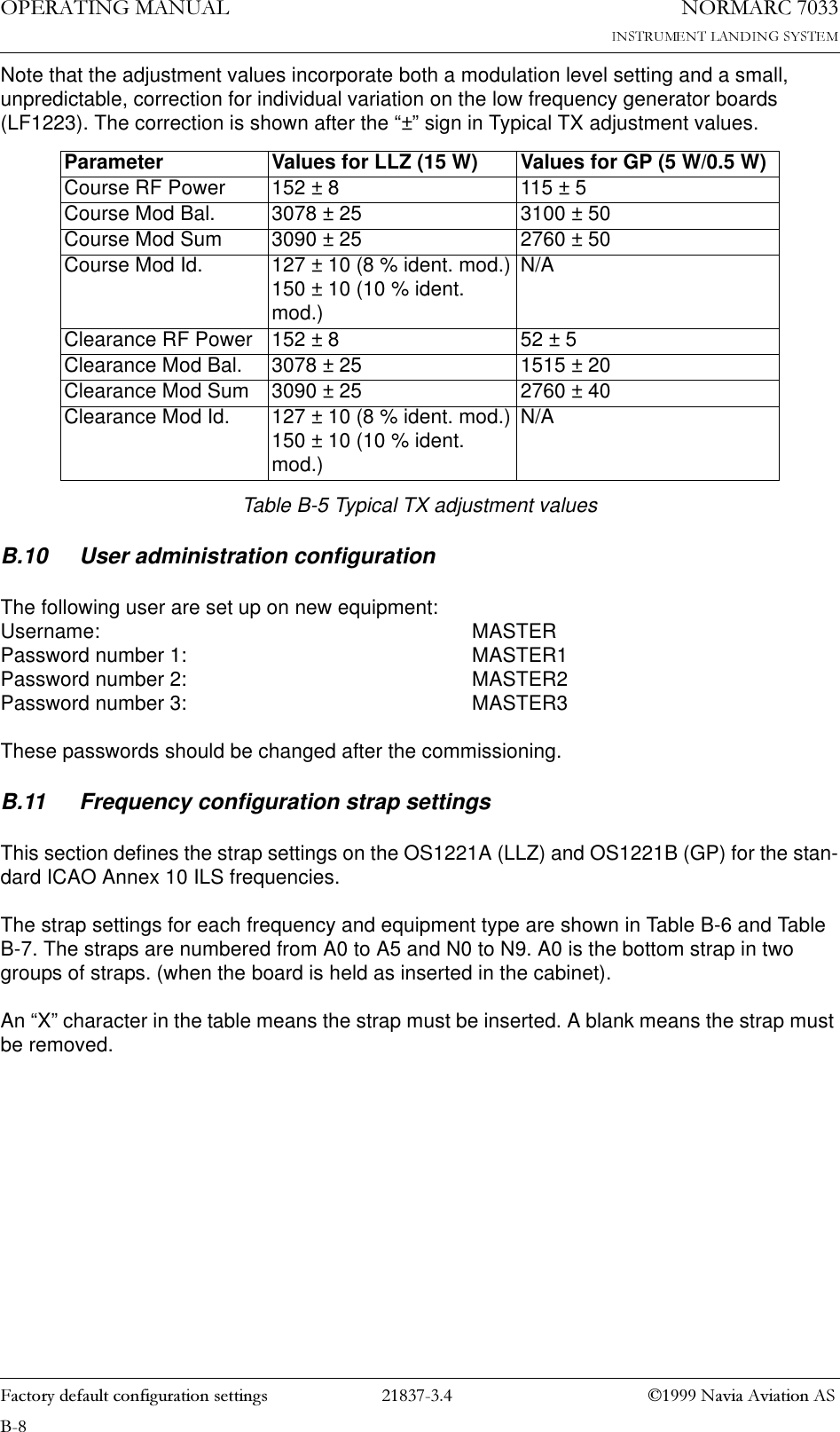
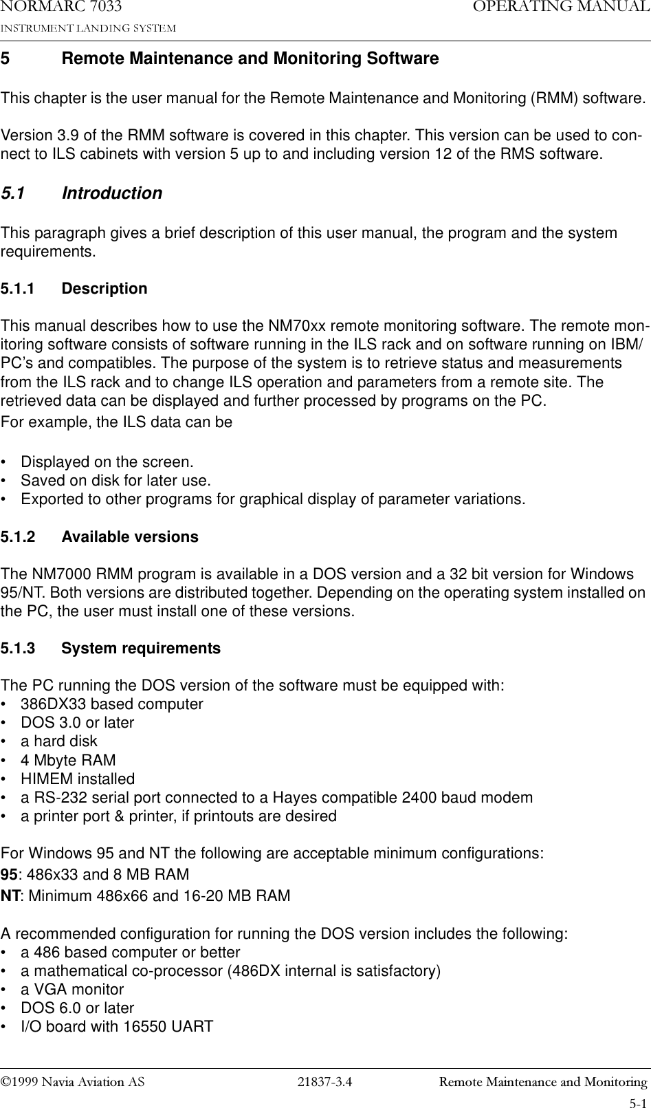
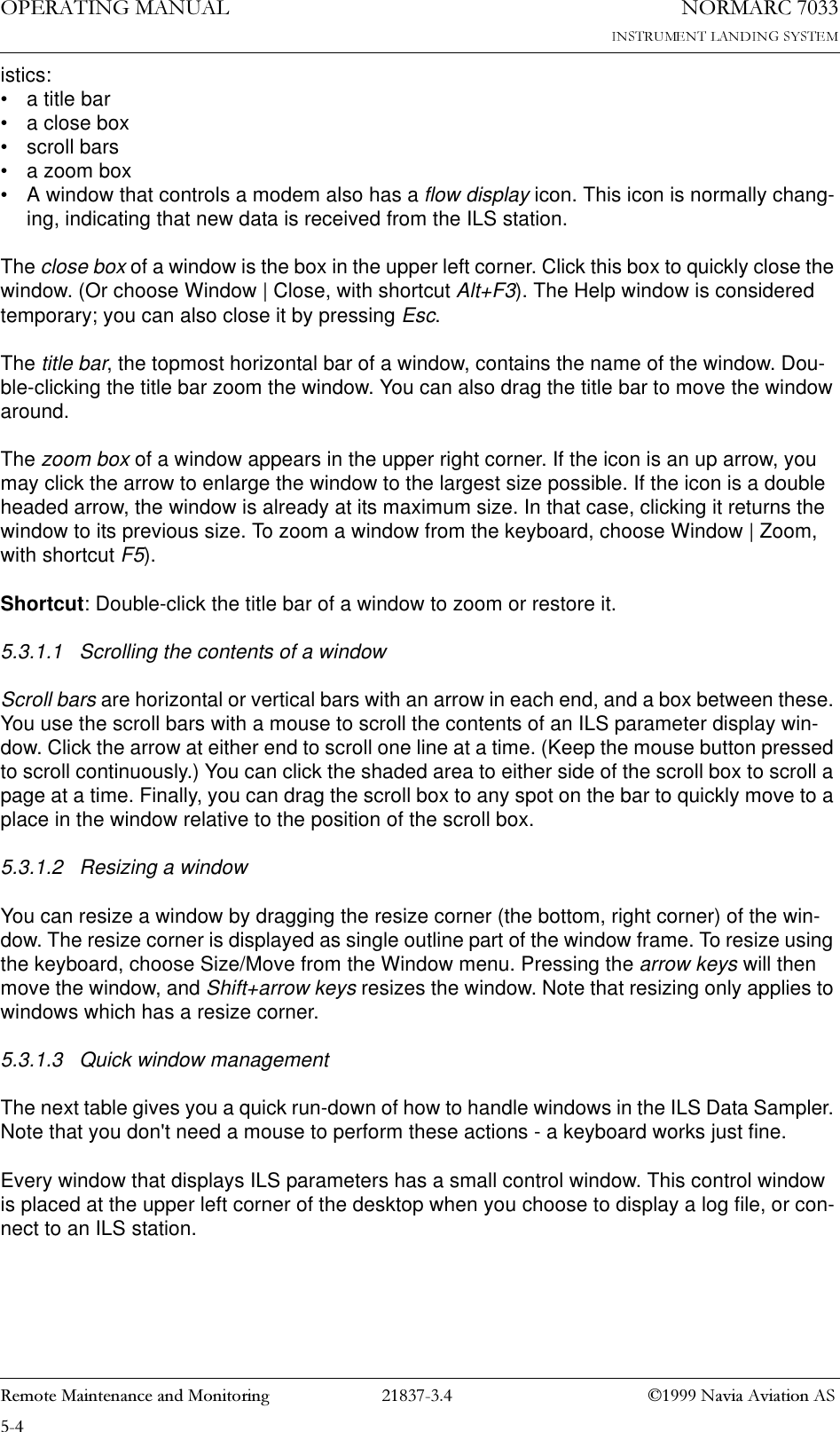
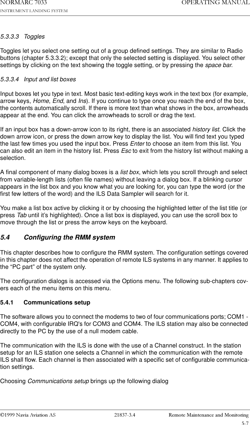
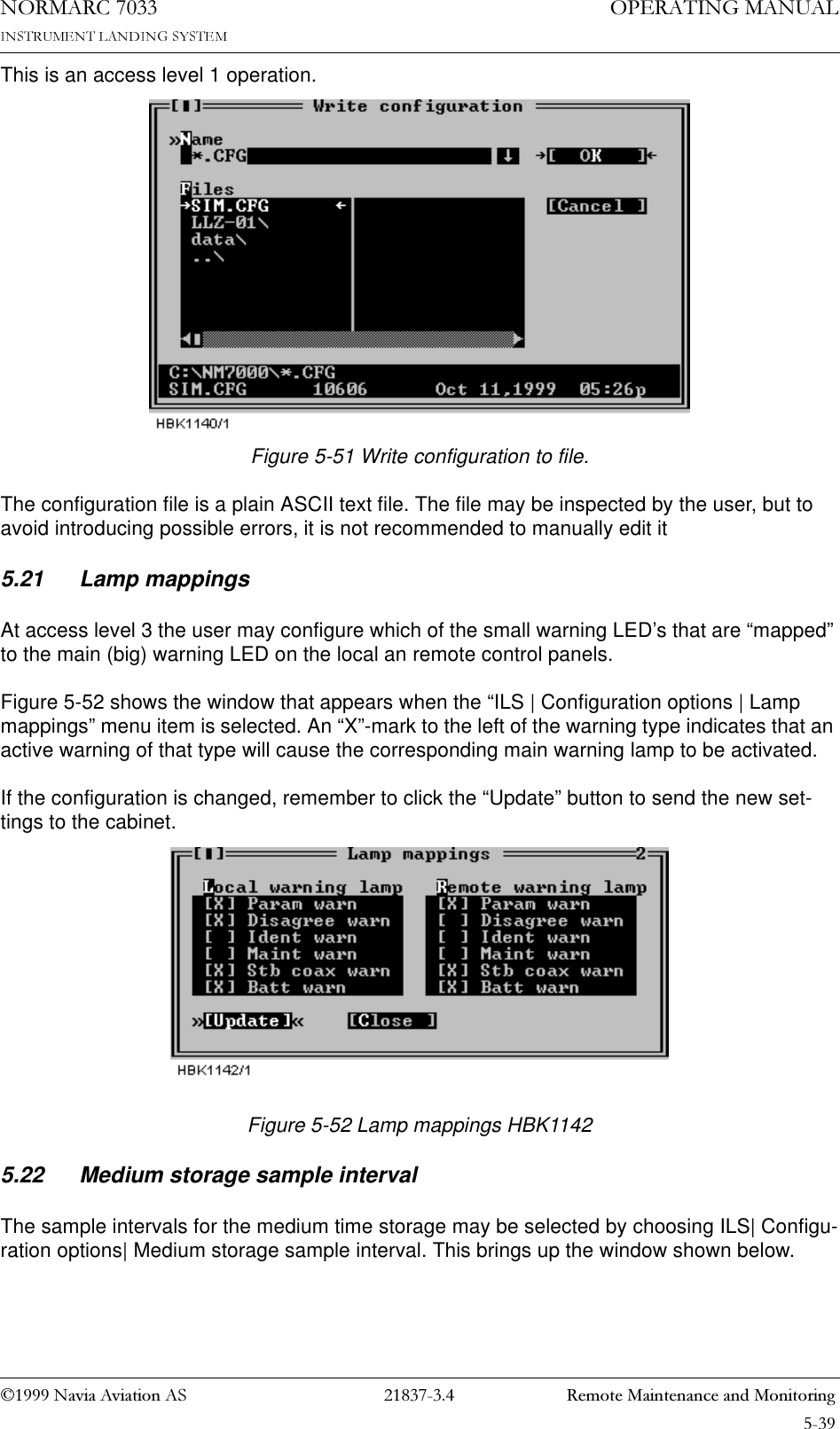
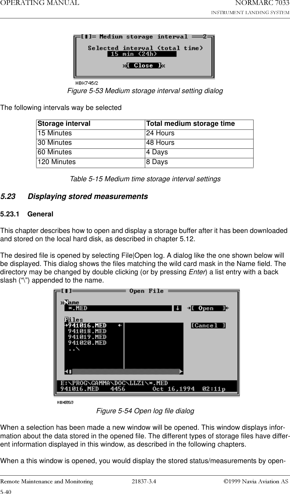
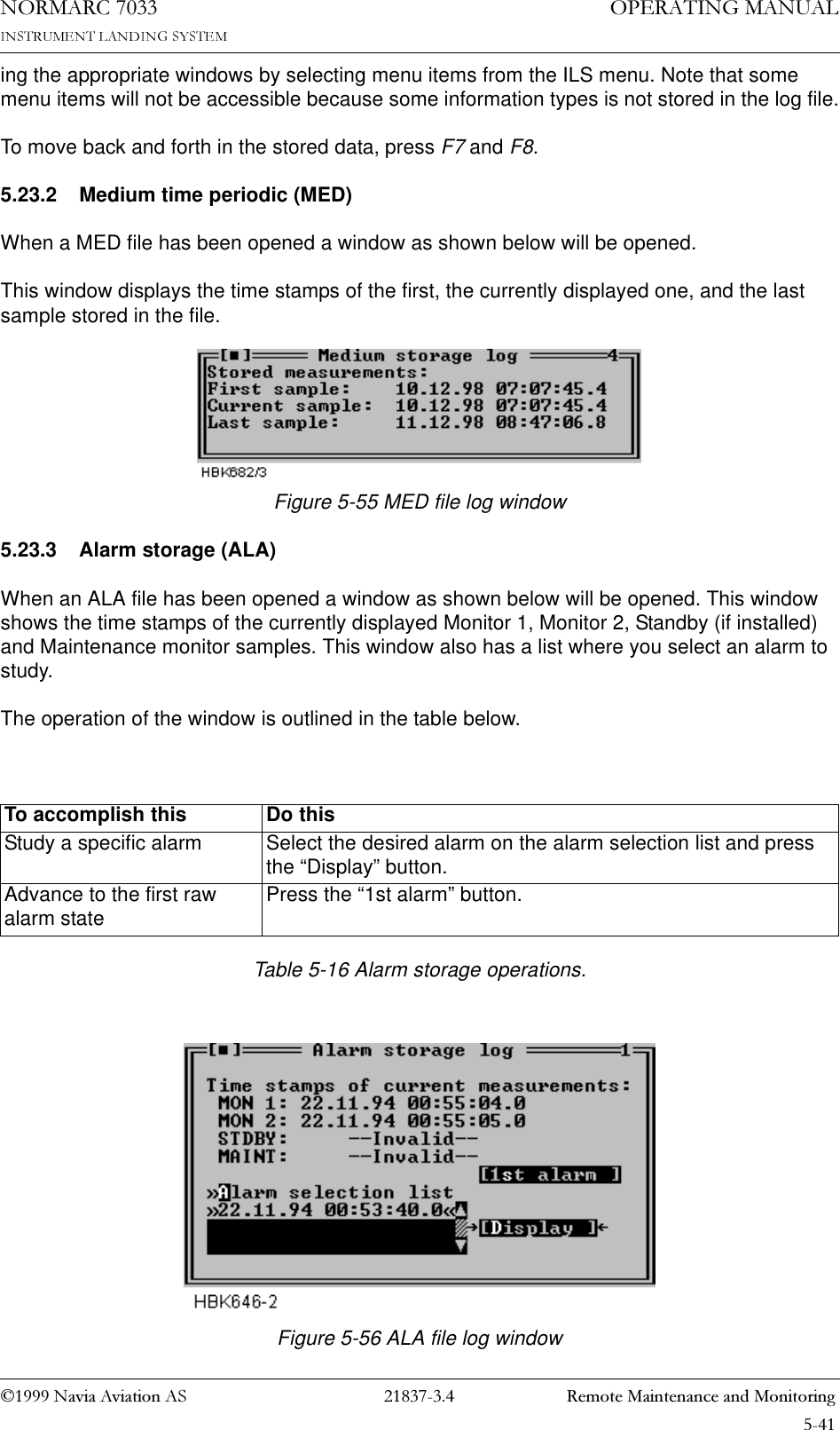
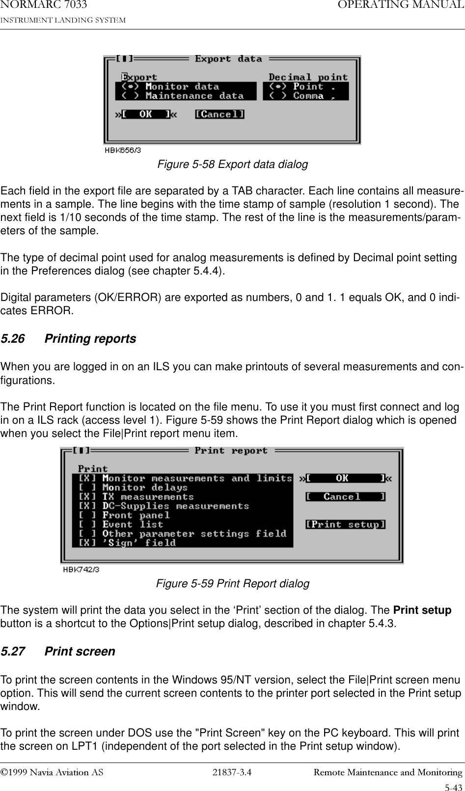
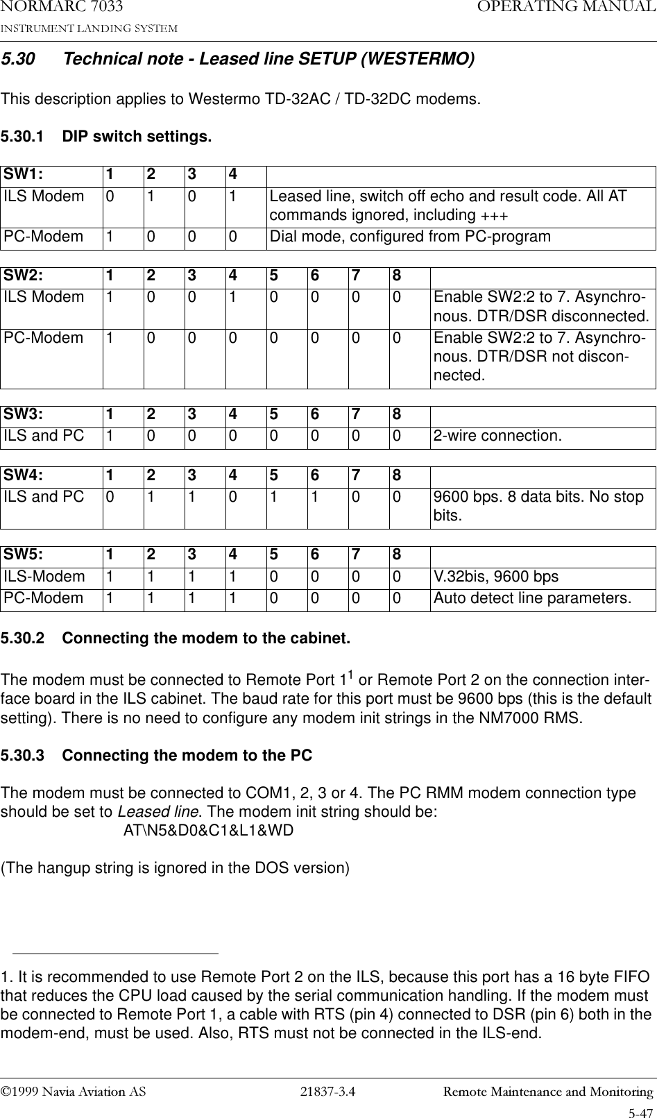
![1DYLD$YLDWLRQ$6 0DLQFDELQHW23(5$7,1*0$18$/1250$5&Figure 3-6 A typical toggle screen: TX1 90Hz on/off.3.3.2.4 Input/Store screenThe user can change the various parameter alarm and warning settings in the input/storing-screens. A virtual cursor is controlled by the <PREV> and <NEXT> keys. An input field num-ber will blink if the cursor is moved to the correct position. The blinking limit values can now be changed by pushing the plus «+» and minus «-» keys. If the input field is digital, the valid options will be «False» and «True» when the plus «+» and minus «-» keys are pushed.When all the input numbers in the screen are changed to the preferred new values, the cursor must be moved to the (STORE)-field in the upper left corner. When the cursor is placed at this (STORE)-field, the brackets will start blinking. The <ENTER> key will now store the new val-ues on the screen in the ILS. The <ESC> key leaves the screen unchanged.Figure 3-7 A typical input/store screen: CL DDM3.3.2.5 The quick read screensThe quick read screens are access by pushing the <QUICK READ> key. The key toggles between the original menu tree and the quick read screens. The <QUICK READ> button can be pushed at all times, not changing the original menu-screens. The quick read screens include only the basic monitor readings. The <PREV> and <NEXT> keys step through the quick read screens.Figure 3-8 A typical quick read screen: CL.3.3.3 The access levels.The level 3 menu options must be entered by typing a 4 character password. The level 2 menu can be entered as an ordinary menu-option.3.3.3.1 Level 2To enter the level 2 menu option, the front panel switches must be in the LOCAL and MAN-UAL positions. The remote panel access switch must also be in ACCESS position. The user is TX 1 90 Hz on/off [90 Hz tone on]CL <store> M1 M2 DDM.: 0.1% 0.1%Al U +1.5% +1.5%Wa U -1.5% -1.5%CL %DDM %SDM RFvM1 0.1 40.0 3.0M2 0.1 40.0 3.0](https://usermanual.wiki/Leidos/NORMARC7033.Normarc-7033-Instrument-Landing-System-Operating-Manual/User-Guide-90099-Page-29.png)
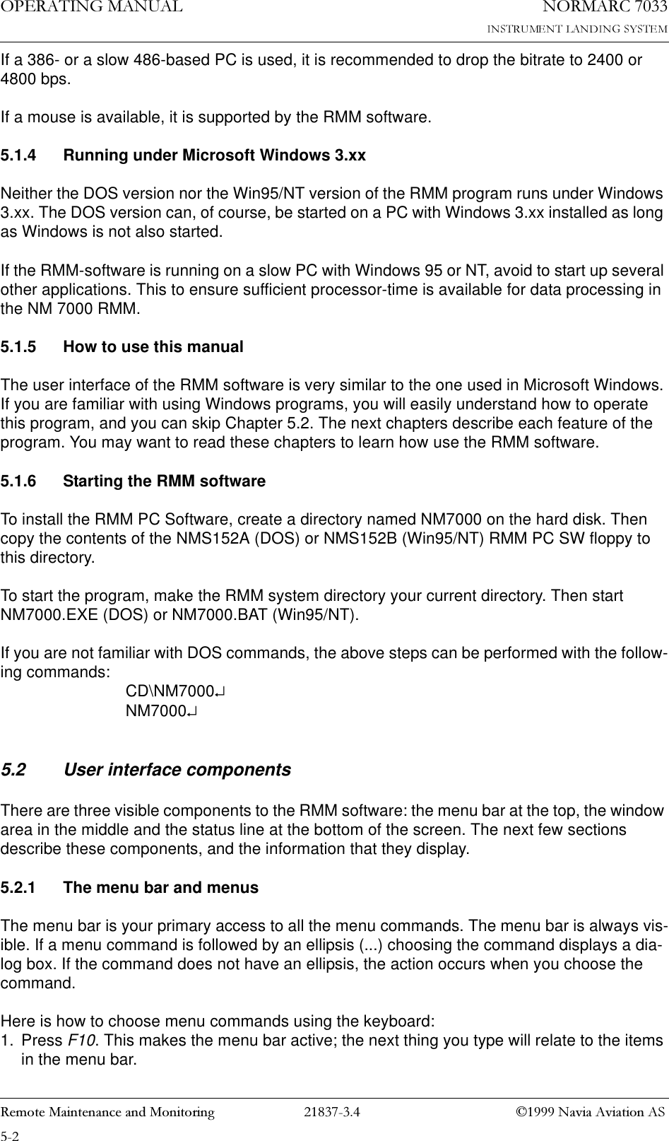
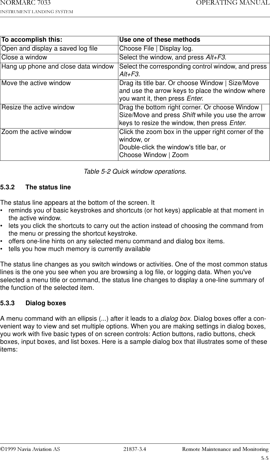
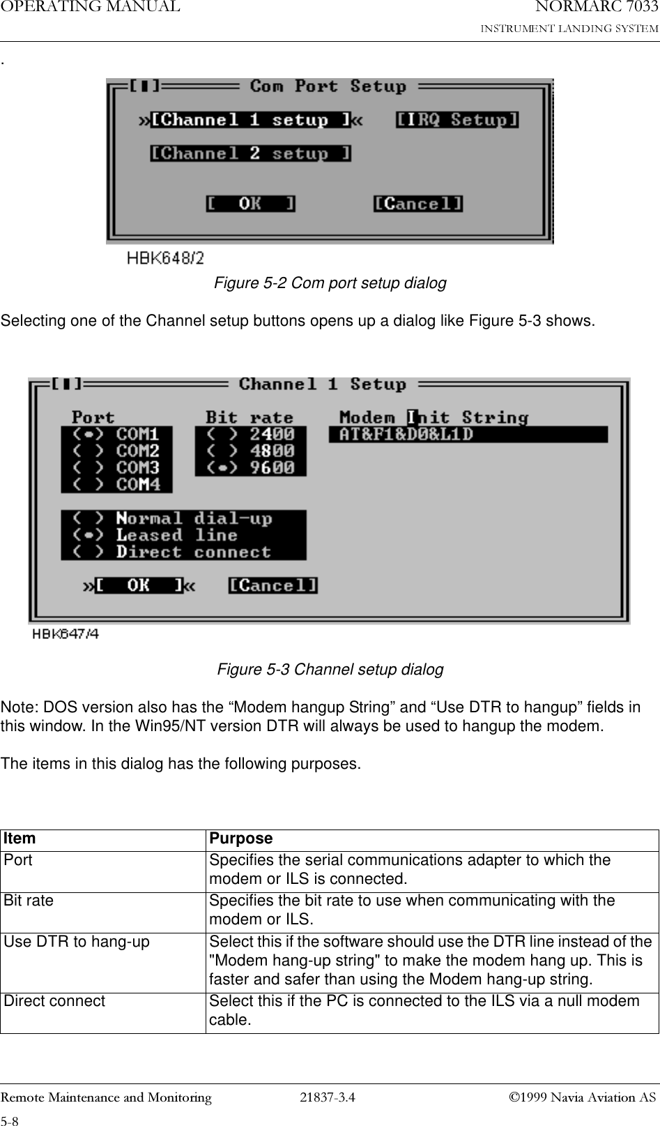
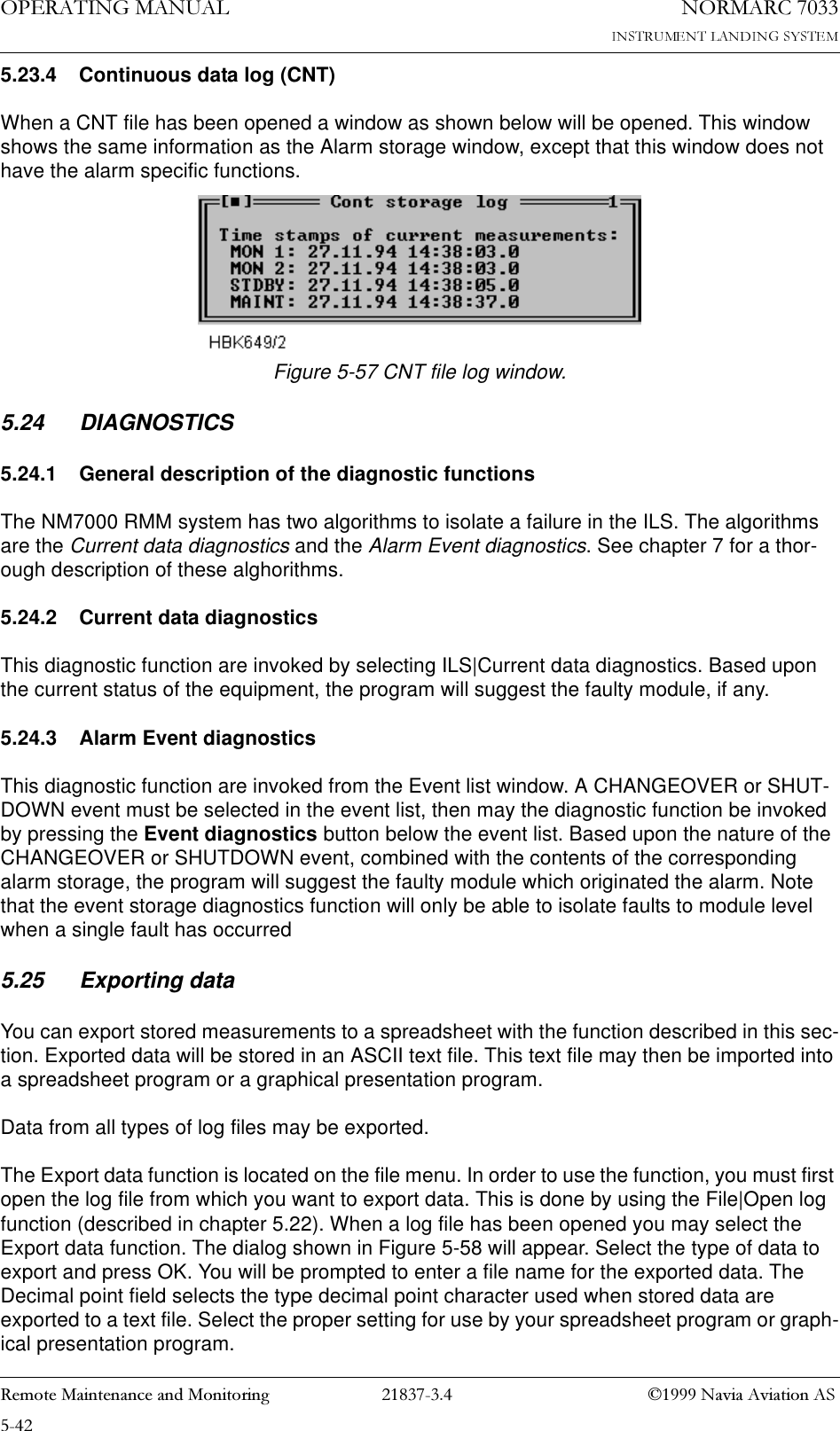
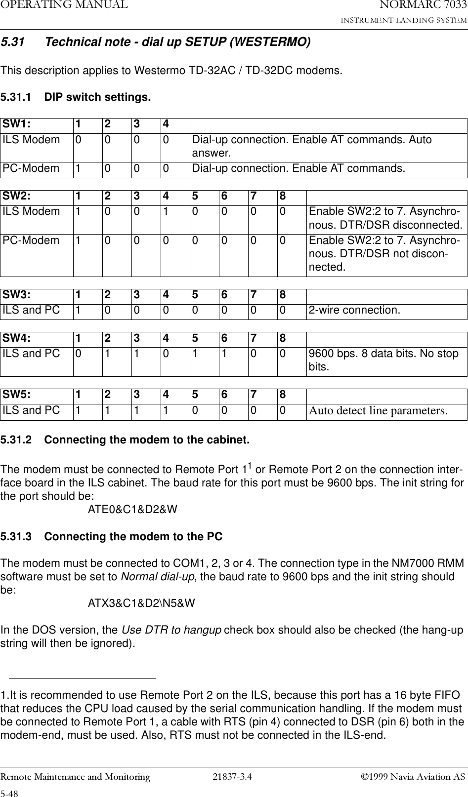
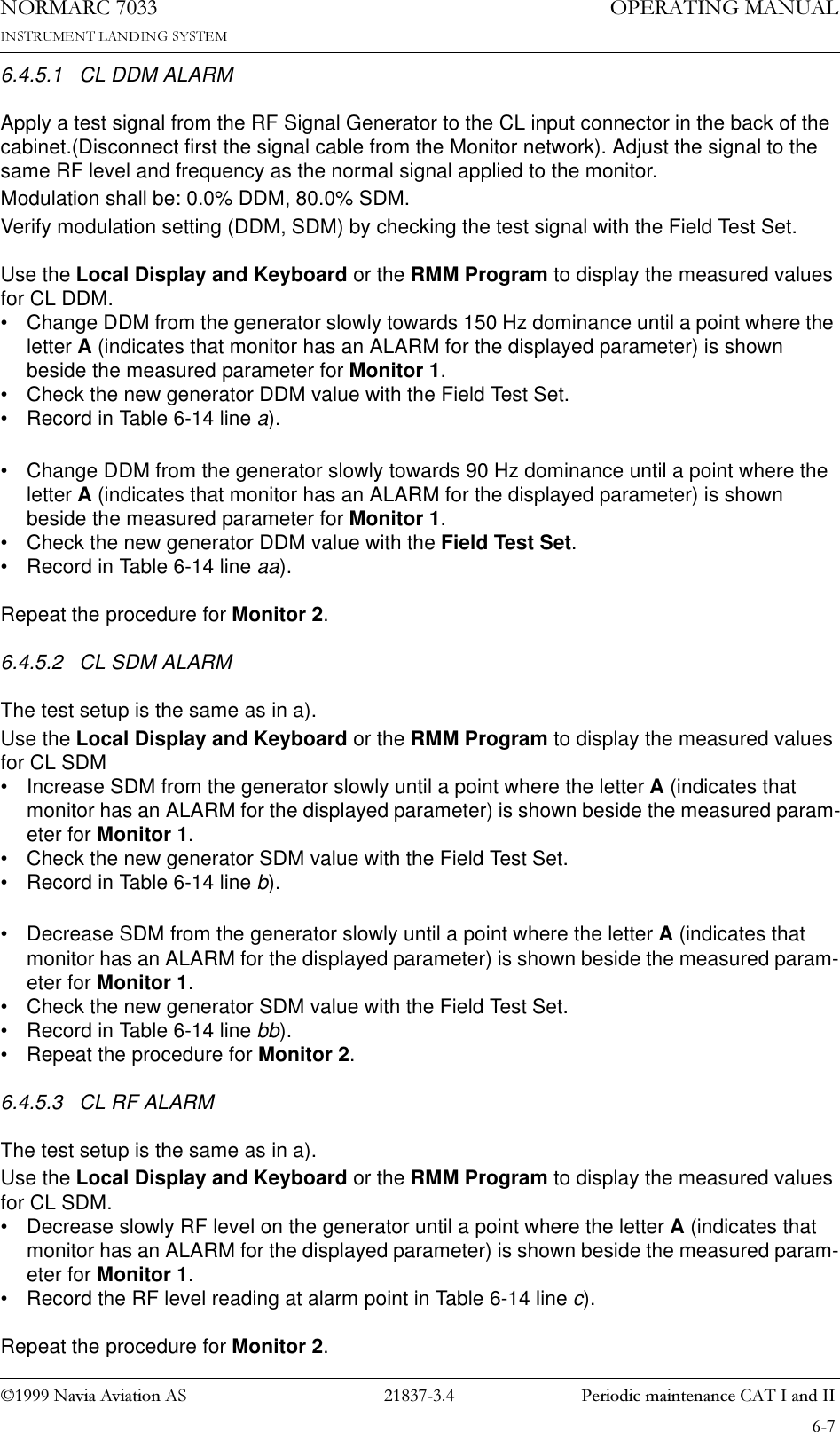
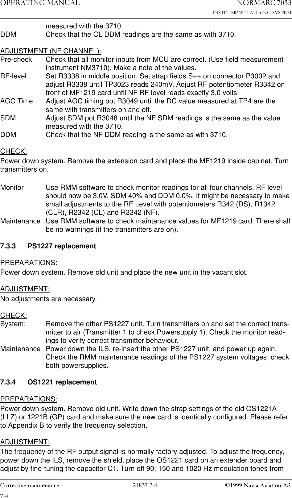
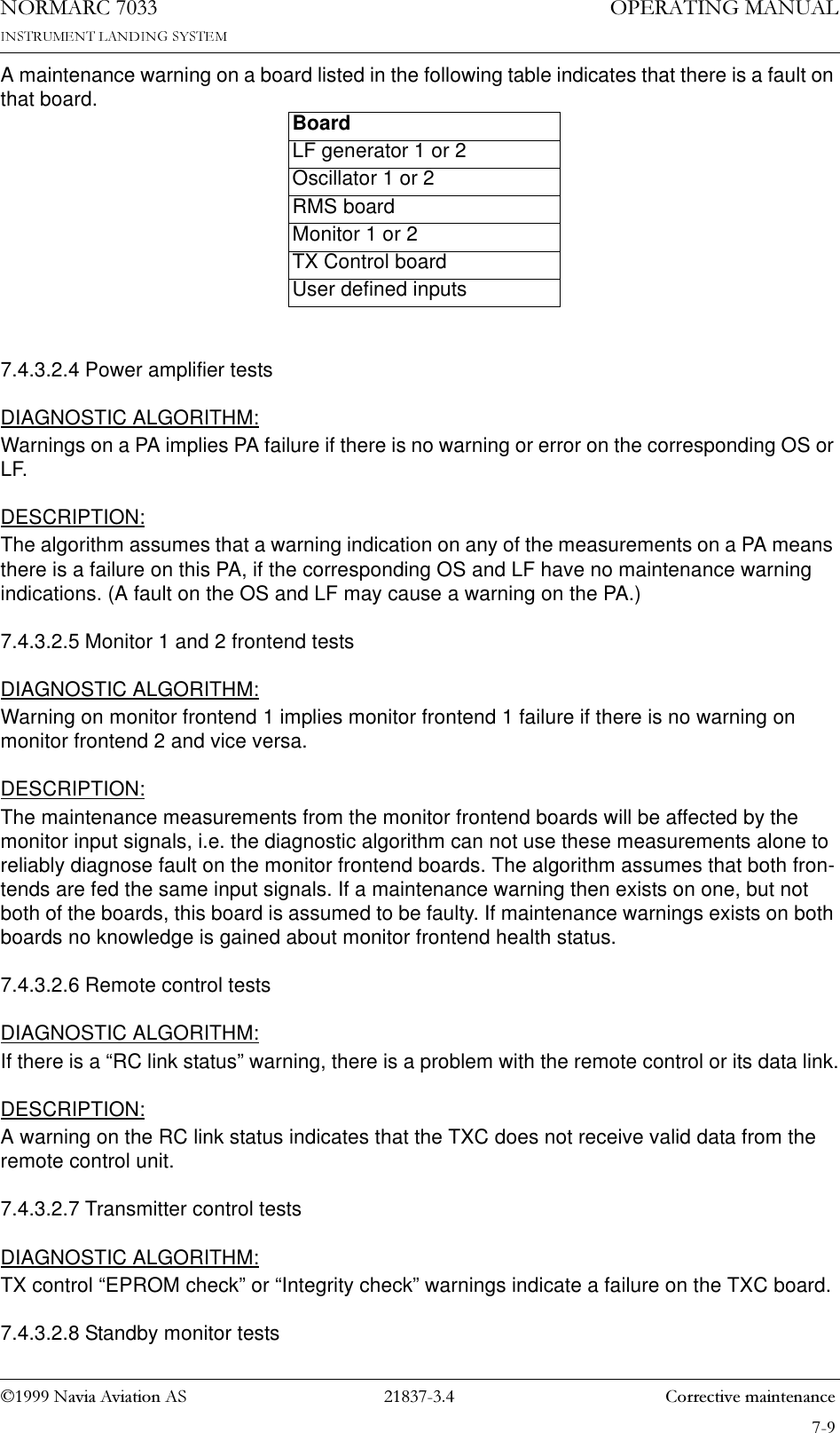
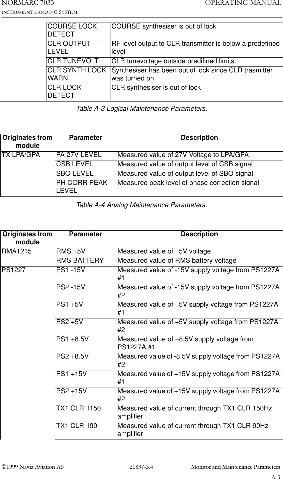
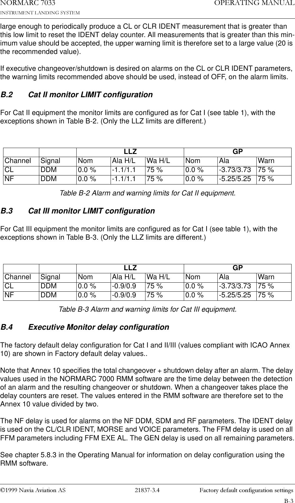
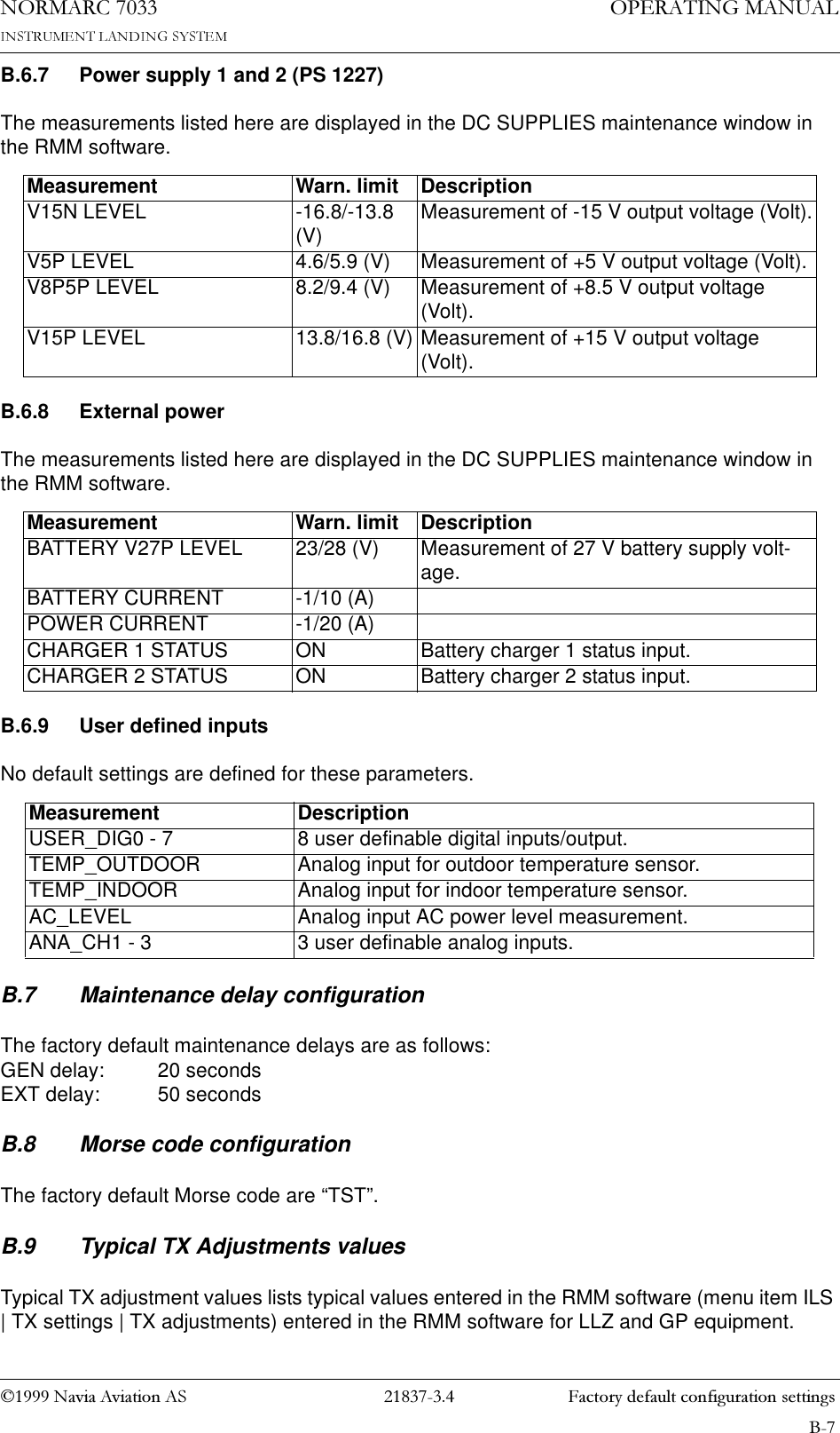
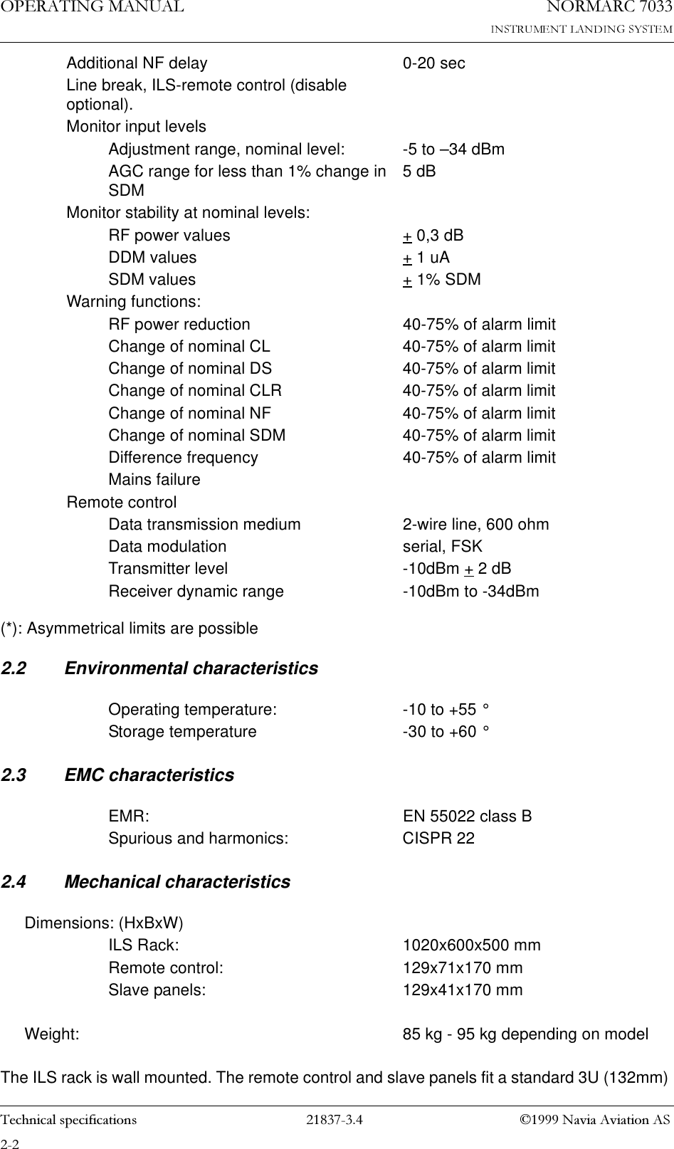
![1DYLD$YLDWLRQ$6 3HULRGLFPDLQWHQDQFH&$7,DQG,,23(5$7,1*0$18$/1250$5&6.4.3.3 RF Phase • Connect the Oscilloscope to SBO test connector on Course Tx1 Section via 50 ohm test cable. NOTE:Set the scope's input mode to DC.Set the oscilloscope in normal trigger mode such that the waveform below can be observed.The observed waveform should resemble the NORMAL graph on the left.6.4.3.4 CSB waveform check. LF phaseSwitch on Course Tx1.• Connect the Oscilloscope to CSB test connector on Course Tx1 Section via 50 ohm test cable.• Set the Oscilloscope input mode to DC.Look for the intermediate peaks of the CSB demodulated waveform. Check that the waveform resembles the graph below (left). The intermediate waveform peaks shall have the same max-'(02'8/$7('6%21250$/ ,0%$/$1&(+]+]'(02'8/$7('6%2G%32:(5'(02'8/$7('6%26,*1$/1250$/ '(02'8/$7('6%26,*1$/5)3+$6((5525](https://usermanual.wiki/Leidos/NORMARC7033.Normarc-7033-Instrument-Landing-System-Operating-Manual/User-Guide-90099-Page-91.png)