Leidos PDE5 Radio Dosimeter User Manual OPERATION MAINTENANCE MANUAL
Science Application International Corporation Radio Dosimeter OPERATION MAINTENANCE MANUAL
Leidos >
Contents
- 1. Operation and Maintenance Manual
- 2. Supplement to OAM manual
Operation and Maintenance Manual
![SAIC PROPRIETARY - Use or disclosure of the information contained on this page is subject to the restrictions contained on the cover sheet of this document. Page3 RadStarTM Radio Transmission Dosimetry System PREFACE Congratulations! You have made an excellent purchase decision. Science Applications International Corporation's (SAIC's) RadStar™ system will provide improved remote radiation monitoring performance which enables: • New levels of ALARA conformance • Minimum staffing and training requirements • Rapidly deployable monitoring • Cost effective spot monitoring • Outage time reduction • Improved safety In addition, SAIC is committed to providing the total support net required for such a system which can be accessed by calling (800)-962-1632. Enough flexibility has been designed into the RadStar™ Radio Dosimetry system to handle a wide range of remote monitoring applications. Although simple networks can be powered up and run without modifying the factory default configuration, setting up the more complex network architectures will usually require some reconfiguration of operating parameters within the PD-4s™ and PDE-4s™ [or simply, PD(E)-4] teledosimeters. For this purpose, SAIC recommends the use of the included PDRC4 application program which allows users to edit control settings within the PD(E)-4 via a PDR-1™ or PDR-1/S™ Reader. After the network has been configured, it can be monitored and controlled by the RadStar™ application program, RS which is also included. Both RS and PDRC4 are compatible with and can be interfaced to user written applications. Both of these application programs are referenced in this manual to provide a context for describing configuration and control operations. A limited amount of descriptive material concerning the use of these programs is contained herein; however, both are provided with on-line Help which will provide additional details concerning active keys, editing procedures, and setup procedures.](https://usermanual.wiki/Leidos/PDE5.Operation-and-Maintenance-Manual/User-Guide-627515-Page-3.png)


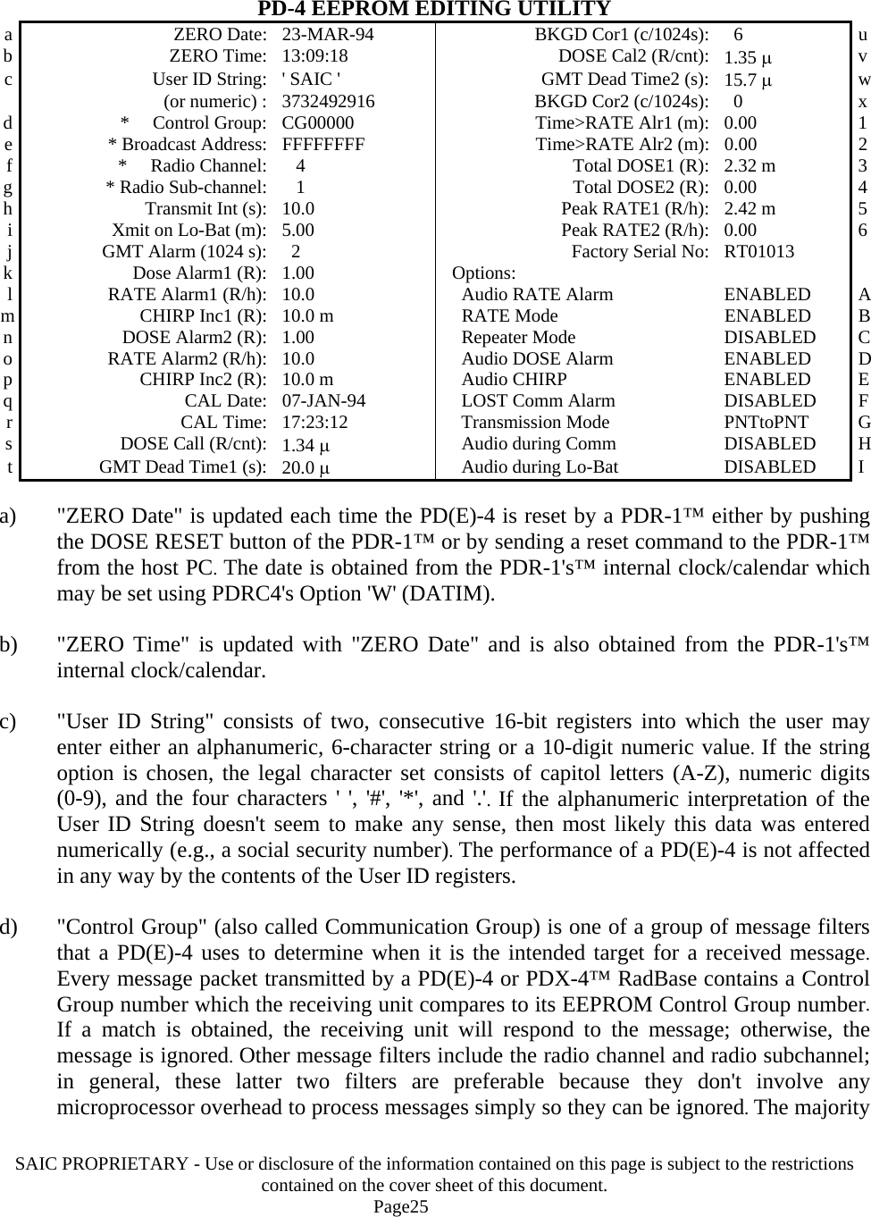
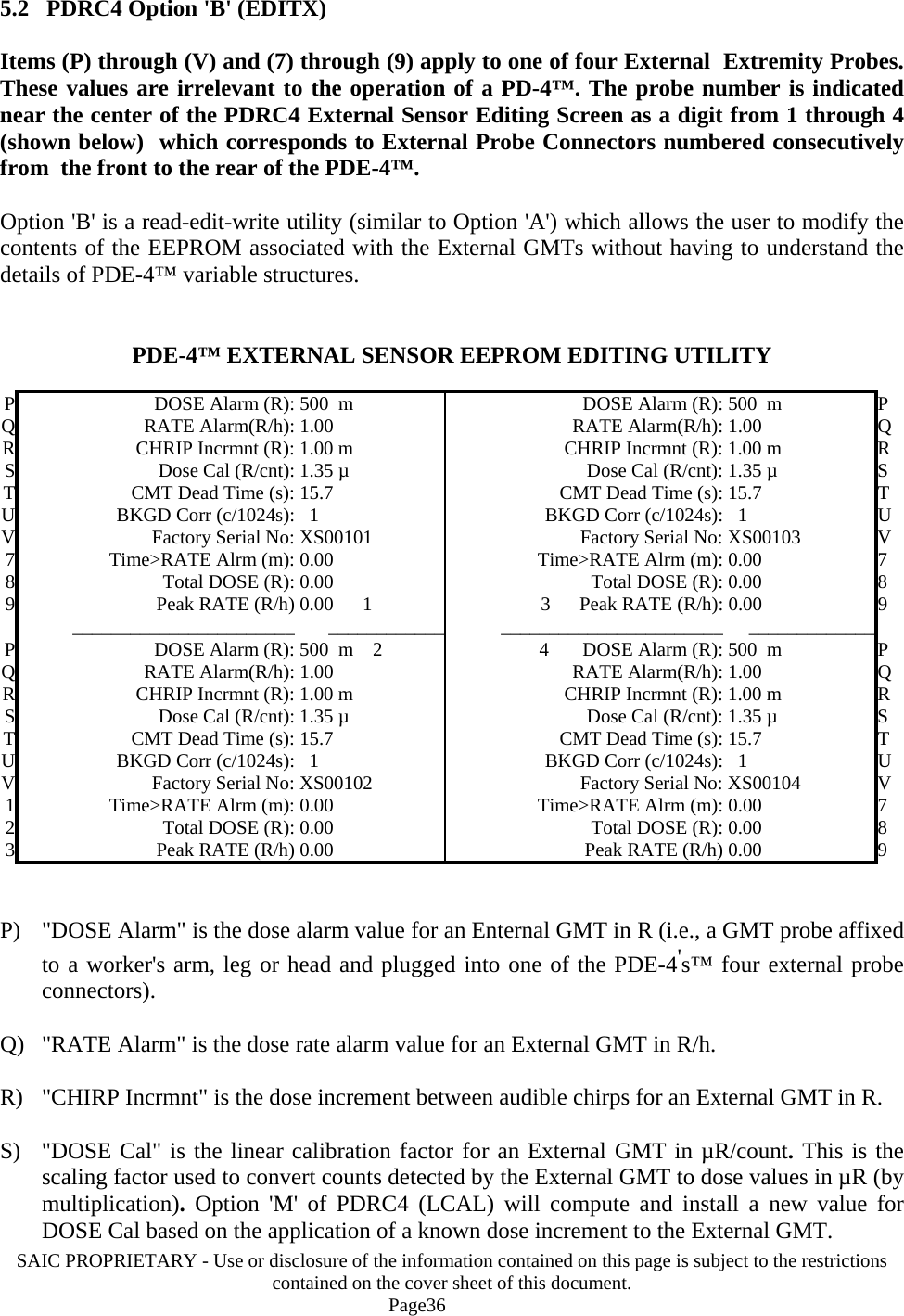
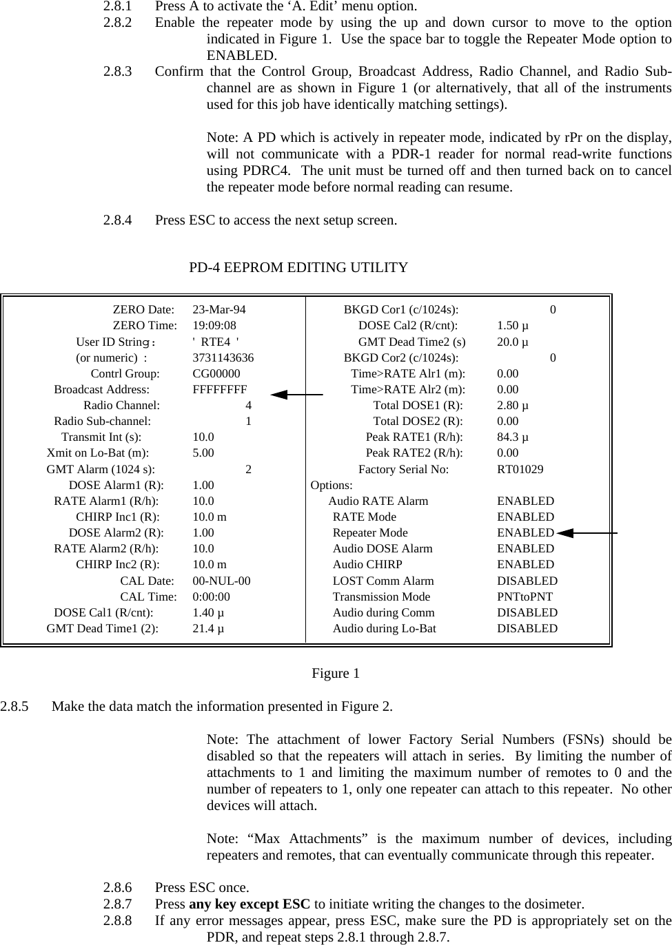
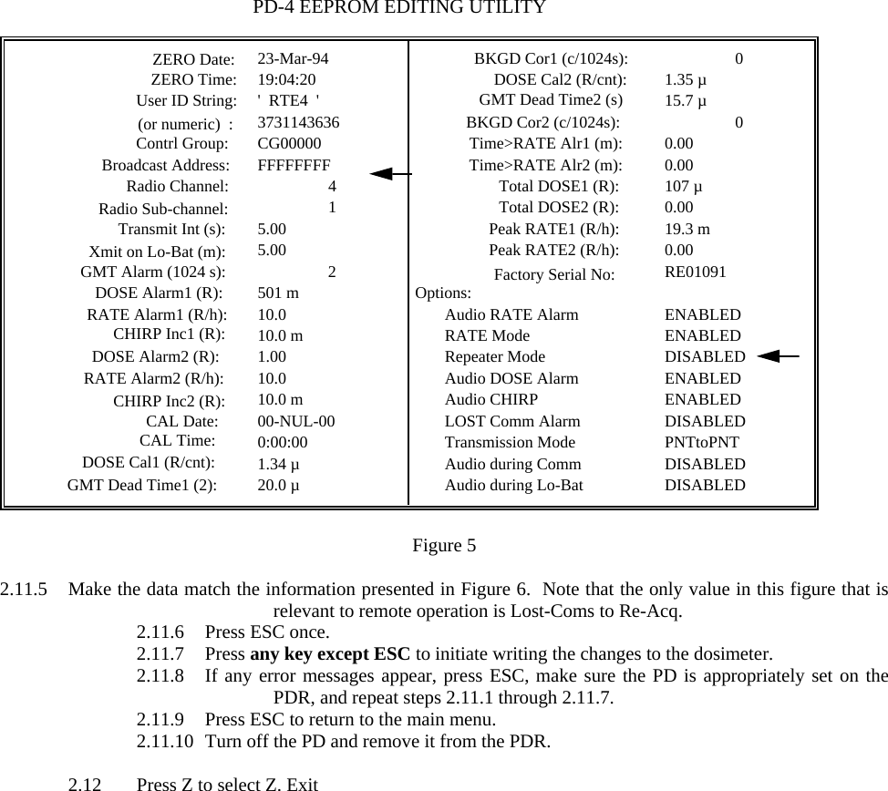
![SAIC PROPRIETARY - Use or disclosure of the information contained on this page is subject to the restrictions contained on the cover sheet of this document. Page24 SAIC recommends that the original packing materials be saved in the event that it becomes necessary to return the PD(E)-4 to the factory. The PD(E)-4 case has been designed for easy decontamination. Should it become necessary to perform any sort of cleaning procedure, note the following points: 1) The PD(E)-4 is not immersion-proof. If necessary, the PD(E)-4 may be wiped down with a damp cloth. 2) Never use any organic solvents on the PD(E)-4. If absolutely necessary, use a dilute solution of a mild detergent (e.g., liquid dishwashing detergent) to dampen the cloth. 5.0 PD(E)-4 EEPROM EDITING A large portion of the PD(E)-4's personality is determined by the firmware in its One-Time Programmable (OTP) microprocessor and cannot be revised without physically changing the processor chip. The remainder of its personality is controlled by values stored in its Electrically Erasable Programmable Read Only Memory (EEPROM). PD-4™ values which control its radiation and communication performance can be edited using a PDR-1™ Reader in conjunction with Option 'A' (EDIT) of SAIC's DOS application, PDRC4. Similarly, values associated with the radiation performance of external sensors of a PDE-4™ can be edited with Option 'B' (EDITX) of PDRC4. The edit screens are shown below with alphabetic characters on the left and right sides of the screens to identify the items that are accessible with the edit controls [numbered items are data generated by the PD(E)-4]. 5.1 PDRC4 Option 'A' (EDIT) Option 'A' is a read-edit-write utility which allows the user to modify the contents of the EEPROM without having to understand the details of PD(E)-4 variable structures. This routine translates the results of the read operation into engineering units for easy editing and then re-translates the modifications back to PD(E)-4 formats prior to the write operation. Option 'A' permits editing of all PD(E)-4 EEPROM values except those associated with PDE-4™ external probes (this latter function is performed by Option 'B'). A number of these options are related to characterization of the radio link and usually will not need to be changed from the factory defaults. These menu items are starred (*) in the display screen representation below; improper or inconsistent values for these parameters will disable communications between PD(E)4-s and PDX-4 RadBases.](https://usermanual.wiki/Leidos/PDE5.Operation-and-Maintenance-Manual/User-Guide-627515-Page-24.png)
![SAIC PROPRIETARY - Use or disclosure of the information contained on this page is subject to the restrictions contained on the cover sheet of this document. Page27 i) "Xmit on Lo-Bat" is the length of the time interval (in minutes) during which the PD(E)-4 will continue with normal radio communications after it detects a low battery voltage condition. At the end of this interval, the PD(E)-4 will continue to operate as a personal dosimeter with no radio functions. Battery threshold levels have been set to provide at least eight hours of operation if the Xmit on Lo-Bat value does not exceed 10 minutes (based on an originally fresh, 9 V alkaline battery). Because the electrical load of the radio modem is relatively high compared to the balance of the PD(E)-4's circuitry, the remaining battery life drops rapidly as the Xmit on Lo-Bat value is increased. j) "GMT Alarm" is the time interval (in units of 1024 seconds) after which the PD(E)-4 initiates a failed GMT alarm if no GMT counts are detected. From one standpoint, this value should be set low to minimize the amount of time that a failed GMT goes undetected. However, lower values for GMT Alarm increase the false alarm rate. For example, the internal GMT of a PD(E)-4 generates about 35 counts/hour at background. The probability that it won't generate a count in 1024 s is exp(-35•1024/3600) = 0.0000475. Therefore, the probability that it won't generate a false alarm in 1024 s is (1-0.0000475) = 0.9999525 and the probability that it won't generate a false alarm in one day is 0.9999525(24•3600/1024) ≈ 0.9960. Thus, there is about a 0.4% probability that a false alarm will be generated during any 24 hour period of operation. GMTs used in PD(E)-4 external probes generate only about 16 counts/hour at background so the probability for one false alarm per day rises to about 59%. If all four external probes are used for a full day, the probability is [1-(1-0.59)4] ≈ 97% that at least one of the probes will false alarm (if GMT Alarm = 1). This false alarm rate drastically drops if GMT Alarm is set to 2, 3, 4, or 5 to 2%, 0.01%, 0.0001%, and 0.000001%, respectively. When the PD(E)-4 is used in radiation fields of 100 µR/h or more, the probability for false alarms drops to essentially zero. GMT Alarm values equal or greater than 2 are preferable. k) "DOSE Alarm1" is the dose alarm value for Internal GMT #1 in R (i.e., a GMT that is built into the PD(E)-4 which would measure trunk or whole body dose in cases where the PD(E)-4 is worn on the back or chest). l) "RATE Alarm1" is the dose rate alarm value for Internal GMT #1 in R/h. m) "CHIRP Inc1" is the dose increment between audible chirps for Internal GMT #1 in R. n) "DOSE Alarm2" may eventually be the dose alarm value for Internal GMT #2 in R. SAIC does not currently install GMT #2 although the physical space, the pulse counter, and the required firmware hooks are already incorporated in the PD(E)-4 design. This is essentially an expansion slot for an additional detector such as an uncompensated GMT to measure shallow dose. The value will not currently affect PD(E)-4 operation. o) "RATE Alarm2" -- Not currently used. p) "CHIRP Inc2" -- Not currently used.](https://usermanual.wiki/Leidos/PDE5.Operation-and-Maintenance-Manual/User-Guide-627515-Page-27.png)
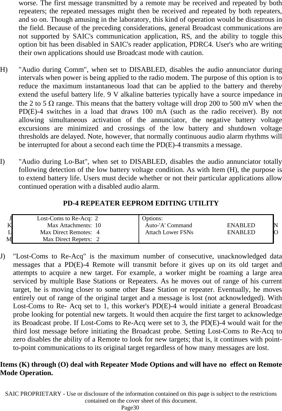
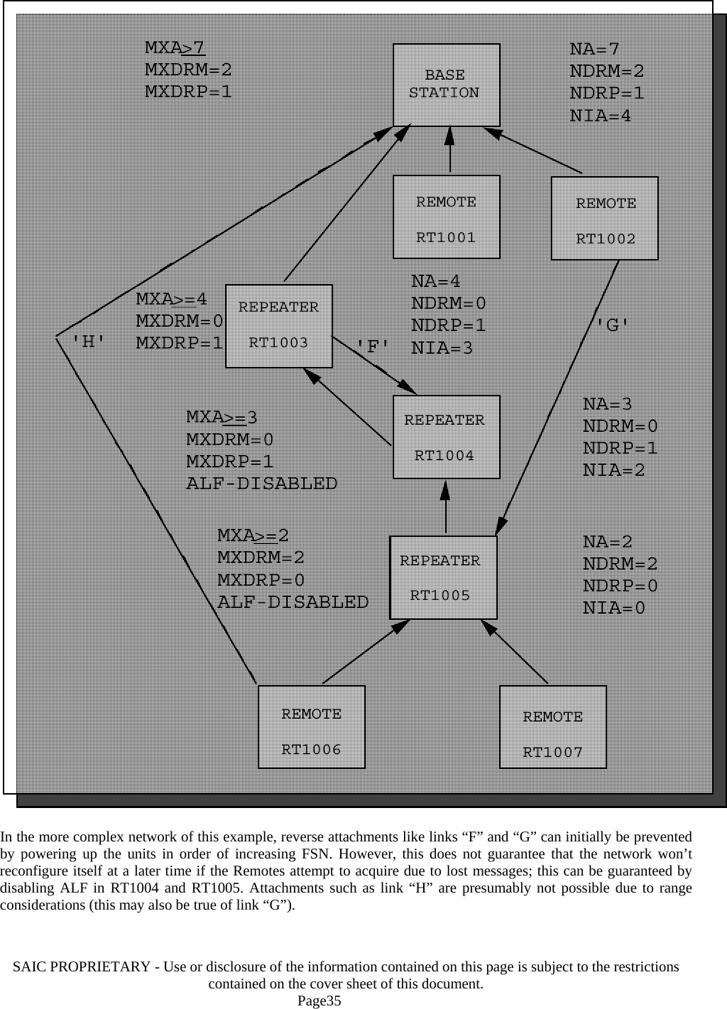
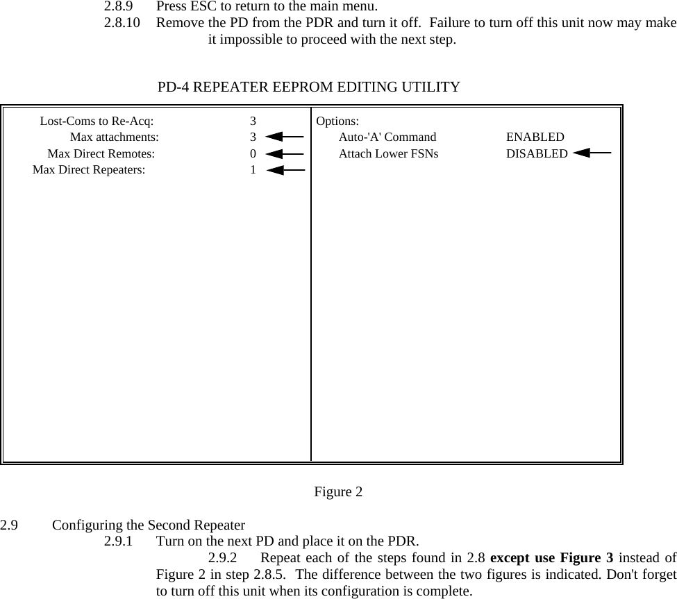
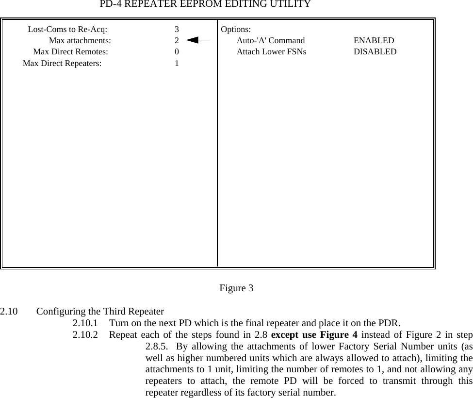
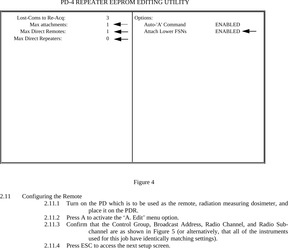
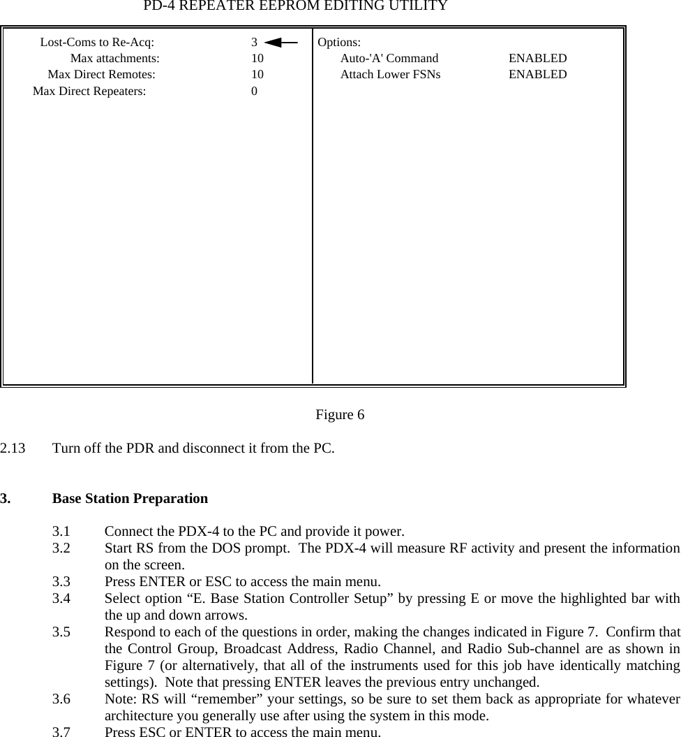
![SAIC PROPRIETARY - Use or disclosure of the information contained on this page is subject to the restrictions contained on the cover sheet of this document. Page31 K) "Max Attachments" has the same meaning in the present context that it did in the Base Station Setup context [similarly for items (L) and (M) below]. It is the maximum number of units (including both Repeaters and Remotes) that can funnel information through this Repeater (either directly or indirectly). L) "Max Direct Remotes" is the maximum number of PD(E)-4 Remote units that can directly attach to this Repeater. Setting this number to zero will force Remote units to attach indirectly through a different Repeater, thus eliminating the possibility of a marginal direct attachment (due to excessive range of the direct attachment). M) "Max Direct Repetrs" is the maximum number of direct Repeater attachments that this Repeater will allow. Typically, it would be set to zero when the Repeater is the most distant Repeater in a multiple Repeater network. This would eliminate the possibility of establishing reverse Repeater links (i.e., Repeater links that lead away from the Base Station rather than toward it). N) "Auto-'A' Command" enables or disables automatic transmission of the 'A' Command which instructs Remote units to transmit a message packet containing its current Alarm settings (along with some status information). When in Repeater mode, a PD(E)-4 inspects each message that it repeats to a direct Remote attachment to determine if the message will cause a change in any operating parameter (e.g., will it cause an alarm level or the transmit interval to change?). In these cases, the Repeater will automatically append the 'A' command to the transmission. When the target Remote responds, it will append the 'a' message to its data message. The purpose of the Auto-'A' command is to reduce radio traffic; the alternative is for the Base Station to send the 'A' command which must then be repeated by each Repeater in the network. IMPORTANT: The SAIC application program, RadStar (RS.EXE), assumes that the Auto-'A' Command option will be enabled in all repeaters of a network (i.e., RS will not sent the 'A'-Command to indirectly connected Remotes). Therefore, if the Auto-'A' option is not enabled in the network Repeaters, RS will never receive the 'a' message from indirectly connected Remotes. O) "Attach Lower FSNs" enables or disables the ability of a Repeater to attach other Repeaters and remotes having a Factory Serial Number (e.g., RT01000 or RE01001) whose numerical part has a lower value than its own. The purpose of this option is to provide the user a simple mechanism for avoiding reverse communication links in automatically configured Repeater networks. This can be accomplished by disabling the Attach Lower FSNs option in all Repeaters and then locating them in order of increasing Factory Serial Number away from the Base Station. The Factory Serial Number of a Remote must be higher than the Factory Serial Number of the Repeater it is expected to acquire. With Attached Lower FSNS enabled, Repeaters pay no attention to Factory Serial Numbers when deciding whether or not to acquire other Repeaters or Remotes (i.e., reverse](https://usermanual.wiki/Leidos/PDE5.Operation-and-Maintenance-Manual/User-Guide-627515-Page-31.png)
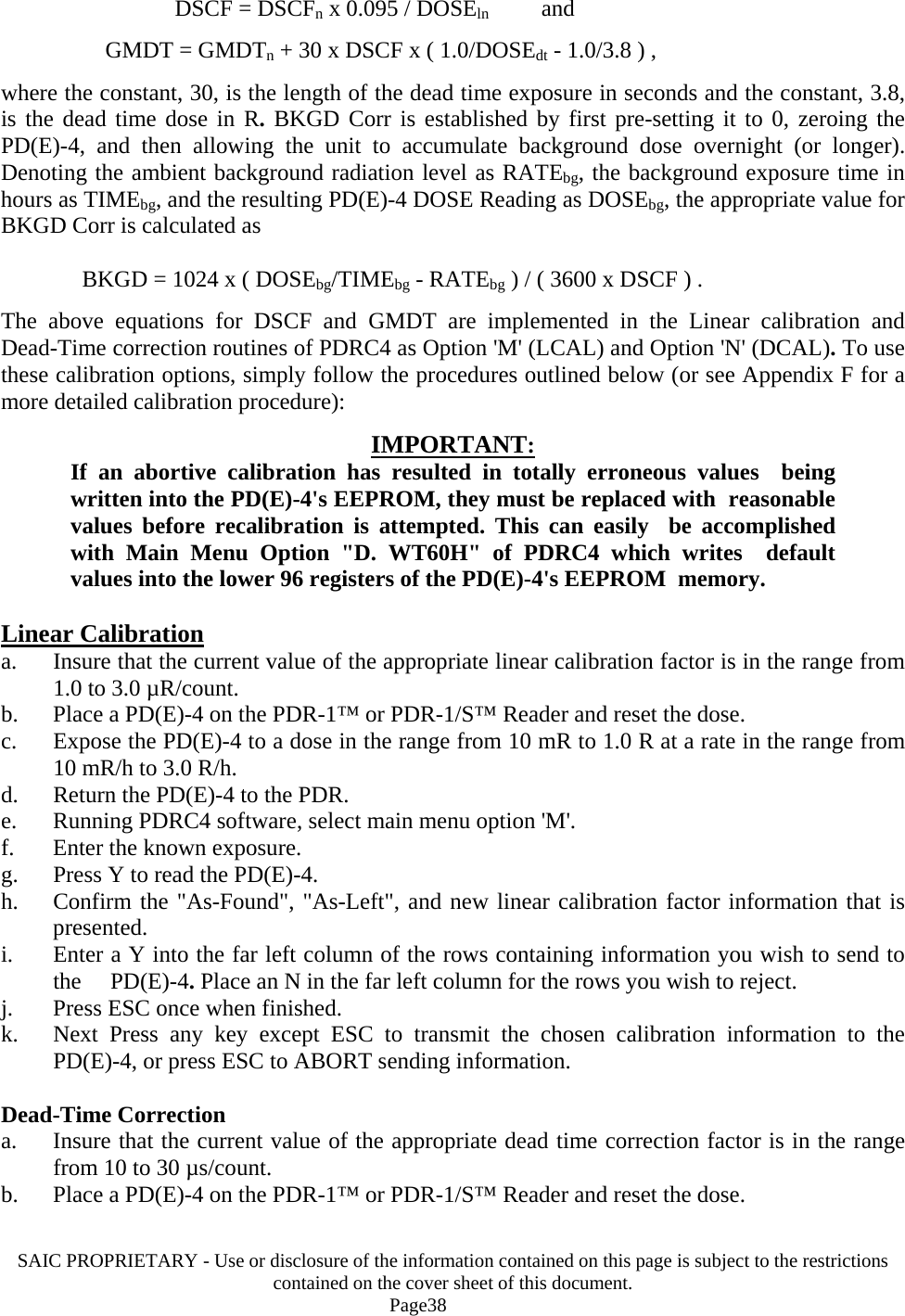
![SAIC PROPRIETARY - Use or disclosure of the information contained on this page is subject to the restrictions contained on the cover sheet of this document. Page37 T) "GMT Dead Time" is the effective time interval in µs that an External GMT is dead (unable to respond to radiation) following a Geiger avalanche. Measured dose increments and dose rates are corrected by the factor, 1/(1-Cτ) where C is the measured GMT counting rate and τ is the GMT Dead Time. Option 'N' of PDRC4 (DCAL) will compute and install a new value for GMT Dead Time based on the application of a known dose increment at a known rate to the External GMT. U) "BKGD Corr" is the spontaneous count rate (in units of counts/1024 s) generated by an External GMT. This includes all counts that are not related to the ambient radiation field such as counts generated by decay of radioactive isotopes in the GMT's structural materials. BKGD Corr is used to correct both dose and dose rate values. The dose correction can be significant if the PDE-4™ is operated continuously at background radiation levels. V) "Factory Serial No", when shipped from the factory, is the serial number of the External Probe to which the calibration factors apply. The Factory Serial No registers for all four external probes are transmitted as part of the PDE-4's™ data message for record keeping purposes. The actual values contained by these registers have no effect on PDE-4™ operation. 7) "Time>RATE Alrm" is the total integrated time in minutes since the last PDE-4™ reset operation that an External GMT measured a dose rate in excess of the RATE Alarm value (these items are not subject to editing). 8) "Total DOSE" is the total accumulated dose in R measured by an External GMT since the last PDE-4™ reset operation (these items are not subject to editing). 9) "Peak RATE" is the maximum dose rate measured by an External GMT since the last PDE-4™ reset operation (these items are not subject to editing). 6.0 PD(E)-4 Calibration Three EEPROM values affect the calibration of each PD(E)-4 GMT Sensor. These are DOSE Cal, GMT Dead Time and BKGD Corr. During factory calibration, nominal values are written into the appropriate Registers before exposing the unit to a 7.5 minute linear calibration dose of 95 mR at 760 mR/h and a 30 second dead time calibration dose of 3.8 R at 456 R/h [the PD(E)-4 is linearly calibrated and then zeroed between calibration exposures]. PLEASE NOTE: Linear calibration must precede dead time correction or totally unreasonable values can be obtained. Acceptable factory defaults are 1.4 µR/count for the linear calibration constant and 20 µs for the dead time correction. Denoting the nominal values as DSCFn and GMDTn and the resulting PD(E)-4 dose readings as DOSEln and DOSEdt, the corrected calibration values are computed as](https://usermanual.wiki/Leidos/PDE5.Operation-and-Maintenance-Manual/User-Guide-627515-Page-37.png)

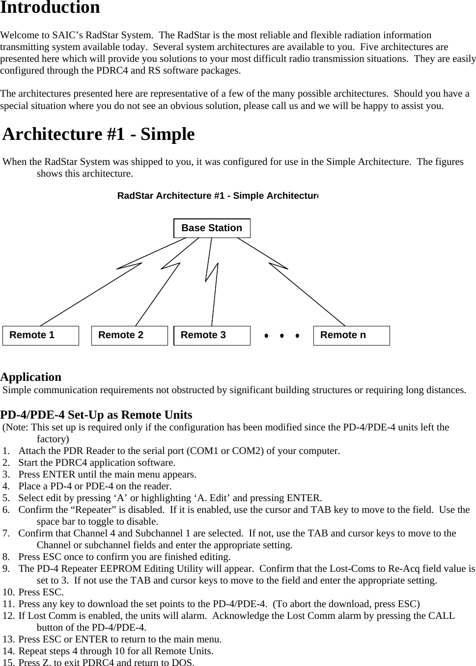
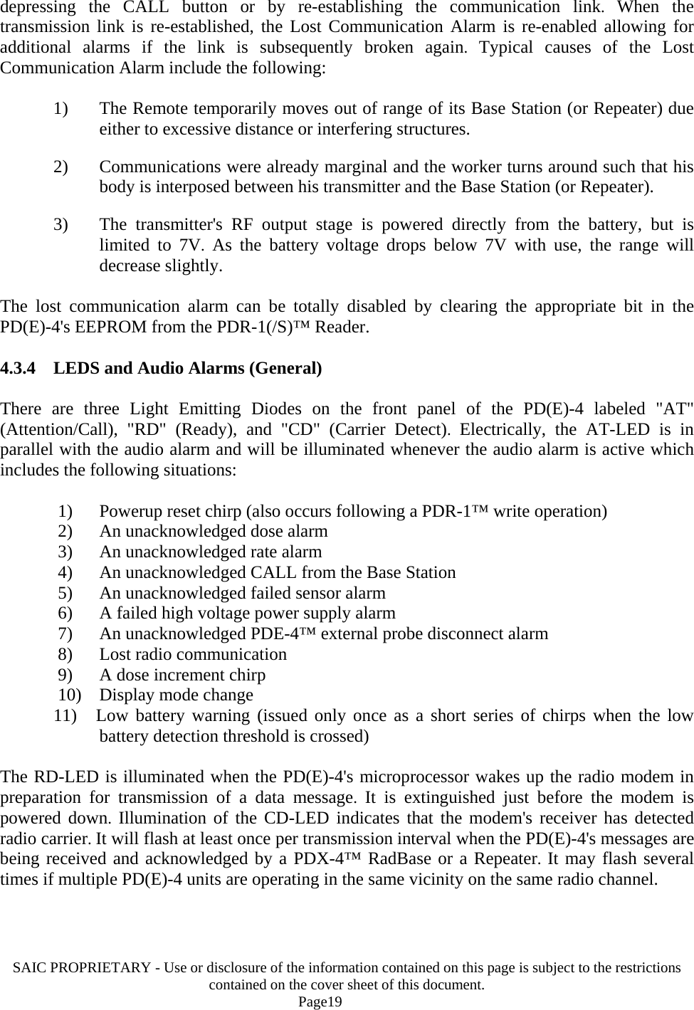
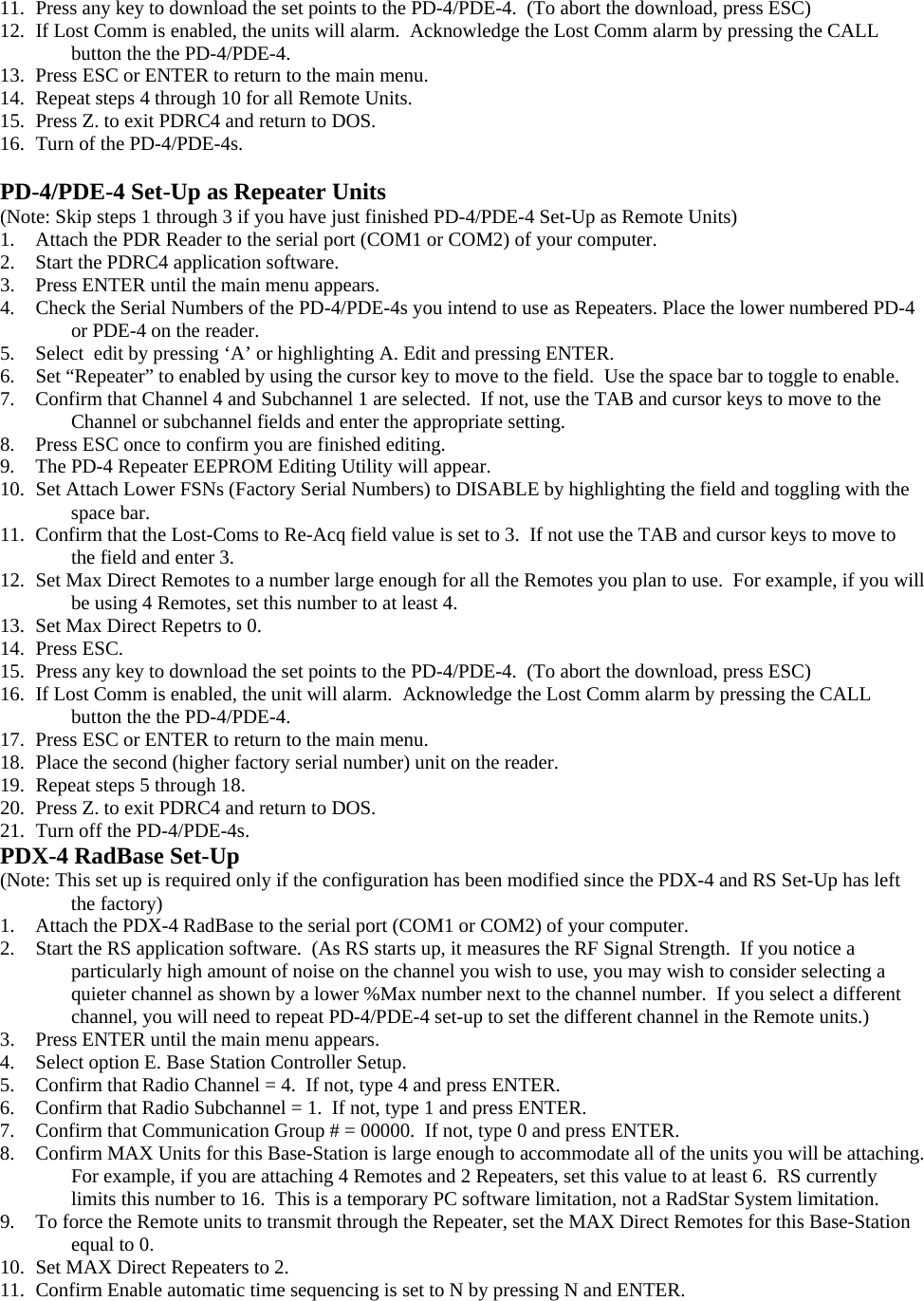
![RF Signal Strength (Channel,%Max): (1,36) (2,35) (3,34) (4,33) (5,31) (6,31) (7,31) Radio Channel = 4; new Channel (1-7)? Radio Subchannel = 1 (1H); new Subchannel (0-65535)? Base-Station (Channel,Subchannel) = (4,1) Communication Group # = 00000 (0000H); New Group # [0-65535 (0-FFFFH)]? Each PD-4 of this Communication Group must contain either 00000 (0000H) or 65535 (FFFFH) in EEPROM Register 17 (11H). MAX Units for this Base-Station = 10; New MAX-Units? 4 MAX Direct Remotes for this Base-Station = 3; New MAX Remotes? 0 MAX Direct Repeaters for this Base-Station = 2; New MAX Repeaters? 1 Your selections allow for 3 Indirect Attachment(s). Save Message-Log(s) in Current Working Directory (Y/N)? Y All messages received during execution of MAIN Menu Option-A will be appended to the files, Rxxxxx.LOG. These files will be created if they don't already exist in current working directory. Figure 7 4. Deploying the system 4.1 Select Menu Option “A. PDX-4 Base Station Controller” by pressing A or highlighting the option and pressing ENTER. 4.2 Repeaters should be deployed with the use of auxiliary power (power transformer or battery packs) as the transceiver is continuously active for a repeater and it draws significant power. Repeaters should also be located at distances and in positions known to allow for reliable communications. 4.3 Turn on the first repeater, i.e., the repeater with the lowest serial number. Allow time for the repeater’s serial number and the word REPEATER to appear on the screen. After a moment, it should change color (to yellow on a color screen) and the display of the PD should show “rPr”. 4.4 Turn on the second repeater. A similar response should occur with the addition of the repeater’s serial number also appearing on the line containing the first repeater. 4.5 Turn on the third repeater. A similar response should occur with the addition of the repeater’s serial number also appearing on the line containing the first repeater. 4.6 Finally, turn on the remote unit. The remote device’s normal monitoring information should appear. 5. Shutdown 5.1 Press ESC to leave the monitoring screen of RS. 5.2 You may wish to restore the Base Station Controller Setup at this time to more general settings, e.g., set the maximum number of units for this base station back to 10, maximum direct remotes to 5, maximum number of repeaters to 2, etc. 5.3 Select Option F to exit the program 5.4 Turn off all devices. 5.5 You may wish to restore the settings of the PDs to more general settings for future use at this time, e.g., disable all repeaters, increase the maximum connections, enable attachment of lower FSNs, etc.](https://usermanual.wiki/Leidos/PDE5.Operation-and-Maintenance-Manual/User-Guide-627515-Page-59.png)
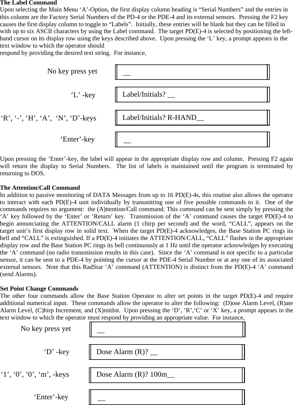
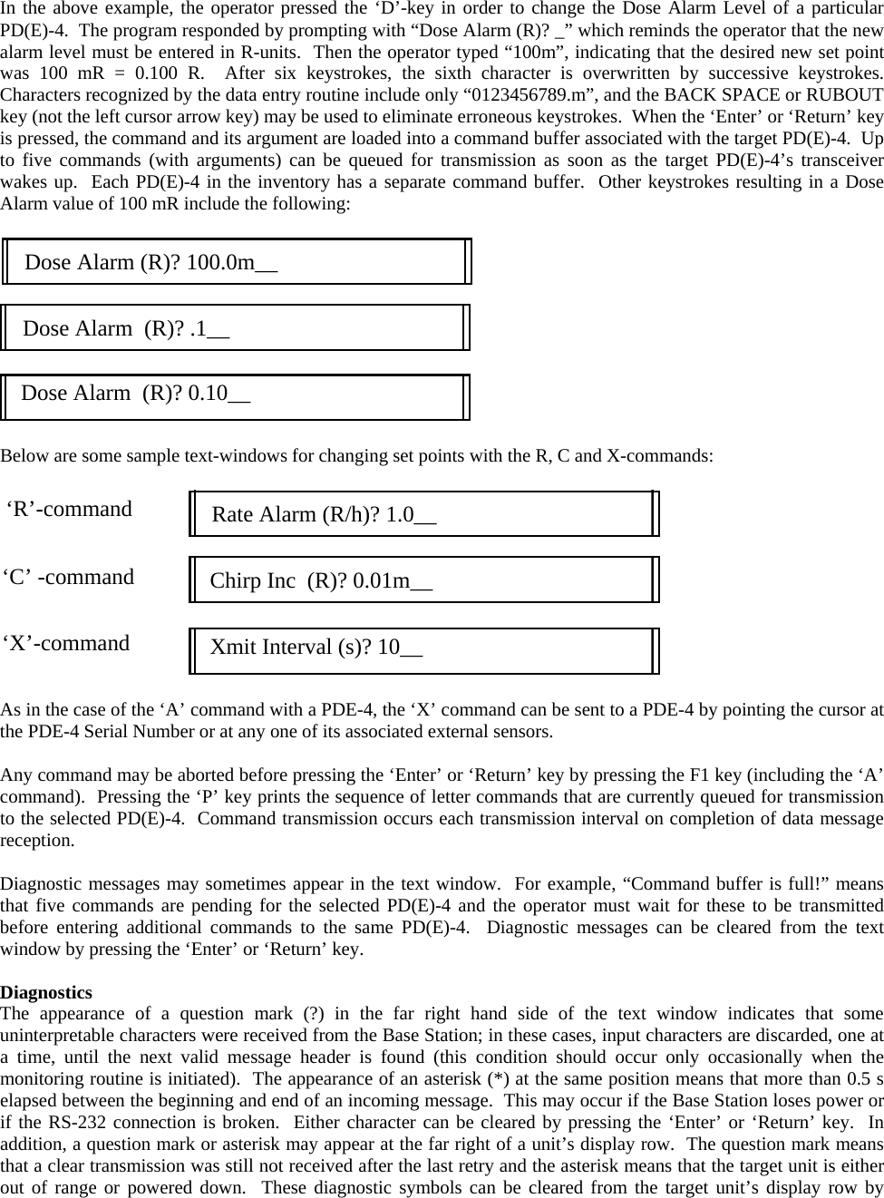
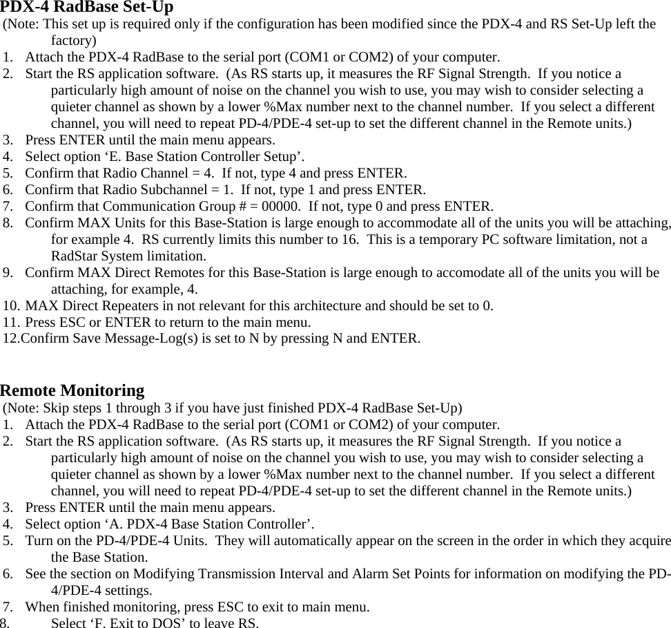
![12. Press ESC or ENTER to return to the main menu. Remote Monitoring (Note: Skip steps 1 through 3 if you have just finished PDX-4 RadBase Set-Up) 1. Attach the PDX-4 RadBase to the serial port (COM1 or COM2) of your computer. 2. Start the RS application software. (As RS starts up, it measures the RF Signal Strength. If you notice a particularly high amount of noise on the channel you wish to use, you may wish to consider selecting a quieter channel as shown by a lower %Max number next to the channel number. If you select a different channel, you will need to repeat PD-4/PDE-4 set-up to set the different channel in the Remote units.) 3. Press ENTER until the main menu appears. 4. Select option ‘A. PDX-4 Base Station Controller’. 5. Deploy the Repeaters. Then turn on the Repeaters. They will automatically appear on the screen. The word REPEATER will first appear in blue, then change to yellow. 7. Deploy the PD-4/PDE-4 units. Then turn on the Remote units. They will automatically appear on the screen as they acquire the Repeaters and Base Station. 8. See the section on Modifying Transmission Interval and Alarm Set Points for information on modifying the PD-4/PDE-4 settings. 9. When finished monitoring, press ESC to exit to main menu. 10. Select ‘F. Exit to DOS’ to leave RS. 11. Turn off the PD-4/PDE-4 Units. Modifying Transmission Interval and Alarm Set Points with RS.EXE All PD(E)-4 settings can be modified using PDRC4 software. In addition, key set points can be modified during normal monitoring operations with the RS software package. Set points which can be modified during monitoring operations include dose alarm, rate alarm, chirp dose increment, and the transmission interval. Also, the ‘C’all command can be sent to any attached unit. General Option ‘A’ of RS provides for simultaneous control and monitoring of up to 16 PD-4s, 10 PDE-4s, or any combination of 16 units that doesn’t exceed the previous two limits. After clearing all buffers of old data, the routine begins looking for PDE-4 activity and inventories the first 16 PD(E)-4 units which report to the Base Station with a DATA Message. Four DATA Items [the PD(E)-4 Factory Serial Number, the PD(E)-4 BATTery condition, and the Dose and Rate Display values for Internal GMT1] are extracted from this first message and printed to the text screen buffer. In the case of a PDE-4, up to eight additional DATA Items are printed on the next four lines (Dose and Rate Display values for up to four Extremity Monitors). The Base Station immediately commands the source PD(E)-4 to transmit its calibration factors and set points (dose alarm, rate alarm, chirp increment, and transmission interval.) Upon reception, all set point values are also printed to the text screen buffer. DATA Items are updated each time a new DATA Message is received (once per transmission interval for each attached unit). Cursor and Text Positioning Methods for interacting with each PD(E)-4 for the Control Group are described below. In general, the target PD(E)-4 is selected by scrolling the text window until the target unit’s serial number is visible and then pointing the text cursor at the desired PD(E)-4 Serial Number, or in the case of a PDE-4, at the Serial Number of one of the Extremity Monitors. The following keys are active: UP_Arrow Moves cursor up 1 line (may also scroll the window) DOWN_Arrow Moves cursor down 1 line (may also scroll the window) LEFT_Arrow Moves cursor to top of text window RIGHT_Arrow Moves cursor to bottom of text window PgUp Scrolls text window up 10 lines (1 page) PgDn Scrolls text window down 10 lines (1 page) Home Positions first page in text window End Positions last page in text window](https://usermanual.wiki/Leidos/PDE5.Operation-and-Maintenance-Manual/User-Guide-627515-Page-62.png)