Lenovo Ideacentre B500 Hardware Maintenance Manual User Idea Centre B500/B505 B505 All In One (ideacentre) Type 0888
2010-08-24
User Manual: Lenovo Lenovo Ideacentre B500 Hardware Maintenance Manual Lenovo IdeaCentre B500/B505 Hardware Maintenance Manual B505 All-in-One (ideacentre) - Type 0888
Open the PDF directly: View PDF ![]() .
.
Page Count: 60

Contents
i
Contents
Chapter 1. About this manual ................................................ 1
Important Safety Information ......................................................................1
Using eSupport ....................................................................................................2
Important information about replacing RoHS compliant FRUs ..2
Chapter 2. Safety information ................................................ 4
General safety ....................................................................................................... 4
Electrical safety .................................................................................................... 5
Safety inspection guide ...................................................................................7
Handling electrostatic discharge-sensitive devices ......................... 8
Grounding requirements ...............................................................................8
Safety notices ........................................................................................................9
Chapter 3. General information ...........................................12
Specifications ..................................................................................................... 12
Chapter 4. General Checkout ...............................................13
Problem determination tips ...................................................................... 14
Chapter 5. Using the Setup Utility ......................................16
Starting the Setup Utility program ......................................................... 16
Viewing and changing settings ................................................................ 16
Using passwords .............................................................................................. 17
Using Device ...................................................................................................... 19
Selecting a startup device ........................................................................... 20
Exiting from the Setup Utility program ................................................ 21

Hardware Maintenance Manual
ii
Chapter 6. Symptom-to-FRU Index.....................................22
Hard disk drive boot error ........................................................................... 22
Power Supply Problems ................................................................................ 23
Beep symptoms ............................................................................................... 24
POST error codes ............................................................................................. 24
Undetermined problems ............................................................................. 26
Chapter 7. Locations ...............................................................27
Locating components and connectors ................................................. 27
Chapter 8. Replacing hardware ...........................................31
General information ....................................................................................... 31
Removing the computer cover ................................................................ 32
Replacing the power supply ...................................................................... 34
Replacing the hard disk drive .................................................................... 36
Replacing an optical drive ........................................................................... 37
Replace the speakers system ..................................................................... 38
Replace the Inverter board ......................................................................... 39
Replacing the Bluetooth module ............................................................. 40
Replacing the thermal module ................................................................. 41
Replacing the CPU ........................................................................................... 41
Replacing the Rear IO module .................................................................. 44
Replacing a memory module .................................................................... 45
Replacing the MXM graphic card ............................................................. 45
Replacing the TV tuner card and wireless card ................................. 46
Replacing the system board ....................................................................... 47
Replacing the touch sensor board .......................................................... 49
Replacing the LCD panel .............................................................................. 51
Replacing the camera .................................................................................... 52
Replacing the keyboard ............................................................................... 53
Replacing the Mouse ..................................................................................... 54
Replacing the power cord or power adapter ..................................... 55
Replacing the remote control .................................................................... 55
Chapter 9. Additional Service Information .......................56
Power management ...................................................................................... 56
Appendix. Statement .............................................................57

Chapter 1. About this manual
1
About this manual 1
This manual contains service and reference information for Lenovo
IdeaCentre B5 computers listed on the cover. It is intended only for trained
servicers who are familiar with Lenovo computer products.
Before servicing a Lenovo product, be sure to read the Safety Information.
The description of the TV card in this manual is only used for the machines
which have the TV card. It is invalid for those machines which do not have
TV card.
Important Safety Information
Be sure to read all caution and danger statements in this book before
performing any of the instructions.
Veuillez lire toutes les consignes de type DANGER et ATTENTION du
présent document avant d’exécuter les instructions.
Lesen Sie unbedingt alle Hinweise vom Typ “ACHTUNG” oder “VORSICHT”
in dieser Dokumentation, bevor Sie irgendwelche Vorgänge durchführen
Leggere le istruzioni introdotte da ATTENZIONE e PERICOLO presenti nel
manuale prima di eseguire una qualsiasi delle istruzioni
Certifique-se de ler todas as instruções de cuidado e perigo neste manual
antes de executar qualquer uma das instruções
Es importante que lea todas las declaraciones de precaución y de peligro
de este manual antes de seguir las instrucciones.
执行任何说明之前,请确保已阅读本书中的所有警告和危险声明。

Hardware Maintenance Manual
2
Using eSupport
For Key Commodities (Examples - hard disk drive, system board,
microprocessor, LCD, and memory)
eSupport can be used to view the list of key commodities built in a •
particular machine serial.
eSupport can be accessed at the following Web site: •
http://consumersupport.lenovo.com
To view the key commodities:•
1. Click Parts information.
2. Under Parts information, click Parts lookup.
3. Under Parts lookup, type the model type and serial number; then
click Continue.
The key commodities are returned in the eSupport record under
Parts shipped with your system.
For the remaining FRUs (the complete list of FRUs at the MT Model level)
eSupport can be used to view the complete list of FRUs for a machine •
type and model.
To view the complete list of FRUs for a machine type:•
1. Point your browser to http://consumersupport.lenovo.com.
2. Type the machine type (Example: 8129) in the Use Quick Path field;
then click Go.
3. Under Browse by product, click Continue.
4. Under Important information, click Parts information.
5. In the Refine results field, select Service parts; then click the entry for
your machine type.
The list of service parts by description, with applicable machine type
model and FRU part number is displayed.
Important information about replacing RoHS compliant FRUs
RoHS, The Restriction of Hazardous Substances in Electrical and
Electronic Equipment Directive (2002/95/EC) is a European Union
legal requirement affecting the global electronics industry. RoHS
requirements must be implemented on Lenovo products placed on the
market after June 2006. Products on the market before June 2006 are
not required to have RoHS compliant parts.
So, if the parts are not compliant originally, replacement parts can
also be noncompliant, but in all cases, if the parts are compliant, the
replacement parts must also be compliant.
Lenovo plans to transition to RoHS compliance well before the
Chapter 1. About this manual
3
implementation date and expects its suppliers to be ready to support
Lenovo’s requirements and schedule. Products sold in 2005, will contain
some RoHS compliant FRUs. The following statement pertains to these
products and any product Lenovo produces containing RoHS compliant
parts.
RoHS compliant Lenovo IdeaCentre B5 parts have unique FRU part
numbers. Before or after June, 2006, failed RoHS compliant parts must
always be replaced using RoHS compliant FRUs, so only the FRUs
identified as compliant in the system HMM or direct substitutions for
those FRUs can be used.
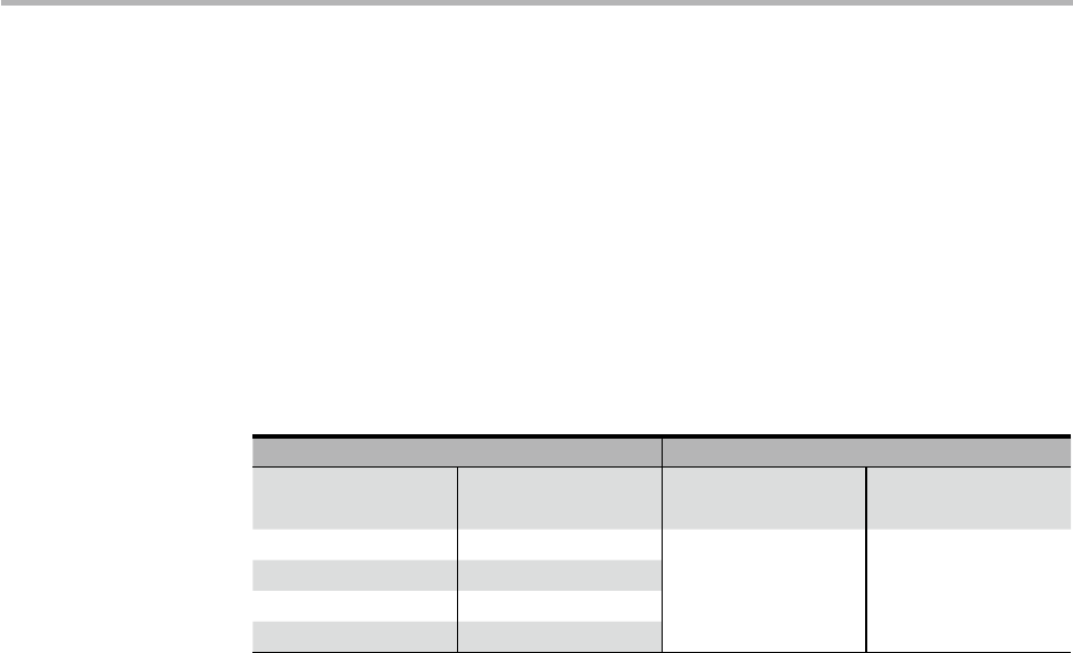
Products marketed before June 2006 Products marketed after June 2006
Current or
original part
Replacement
FRU
Current or
original part
Replacement
FRU
Non-RoHS Can be Non-RoHS Must be RoHS Must be RoHS
Non-RoHS Can be RoHS
Non-RoHS Can sub to RoHS
RoHS Must be RoHS
Note: A direct substitution is a part with a different FRU part number that
is automatically shipped by the distribution center at the time of
order.
Related Web URLs are:
Lenovo information for Suppliers website: •
http://www-03.ibm.com/procurement/proweb.nsf/
ContentDocsByTitle/United+States~Information+for+suppliers
RoHS Directive: •
http://europa.eu.int/eur-lex/pri/en/oj/dat/2003/l_037/
l_03720030213en00190023.pdf
California Senate Bills 20, 50: •
http://www.ciwmb.ca.gov/HHW/Events/AnnualConf/2004/
presentation/MPaparian.pdf

Hardware Maintenance Manual
4
Safety information 2
This chapter contains the safety information that you need to be familiar
with before servicing a computer.
General safety
Follow these rules to ensure general safety:
Observe good housekeeping in the area of the machines during and •
after maintenance.
When lifting any heavy object: •
1. Ensure you can stand safely without slipping.
2. Distribute the weight of the object equally between your feet.
3. Use a slow lifting force. Never move suddenly or twist when you
attempt to lift.
4. Lift by standing or by pushing up with your leg muscles; this action
removes the strain from the muscles in your back. Do not attempt to
lift any objects that weigh more than 16 kg (35 lb) or objects that you
think are too heavy for you.
Do not perform any action that causes hazards to the customer, or that •
makes the equipment unsafe.
Before you start the machine, ensure that other service representatives •
and the customer’s personnel are not in a hazardous position.
Place removed covers and other parts in a safe place, away from all •
personnel, while you are servicing the machine.
Keep your tool case away from walk areas so that other people will not •
trip over it.
Do not wear loose clothing that can be trapped in the moving parts of a •
machine. Ensure that your sleeves are fastened or rolled up above your
elbows. If your hair is long, fasten it.
Insert the ends of your necktie or scarf inside clothing or fasten it with •
a nonconductive clip, approximately 8 centimeters (3 inches) from the
end.
Do not wear jewelry, chains, metal-frame eyeglasses, or metal fasteners •
for your clothing.
Remember: Metal objects are good electrical conductors.

Chapter 2. Safety information
5
Wear safety glasses when you are: hammering, drilling soldering, •
cutting wire, attaching springs, using solvents, or working in any other
conditions that might be hazardous to your eyes.
After service, reinstall all safety shields, guards, labels, and ground wires. •
Replace any safety device that is worn or defective.
Reinstall all covers correctly before returning the machine to the •
customer.
Electrical safety
CAUTION:
Electrical current from power, telephone, and communication cables
can be hazardous. To avoid personal injury or equipment damage,
disconnect the attached power cords, telecommunication systems,
networks, and modems before you open the server/workstation covers,
unless instructed otherwise in the installation and configuration
procedures.
Observe the following rules when working on electrical equipment.
Important: Use only approved tools and test equipment. Some hand
tools have handles covered with a soft material that does not
insulate you when working with live electrical currents.
Many customers have, near their equipment, rubber floor mats
that contain small conductive fibers to decrease electrostatic
discharges. Do not use this type of mat to protect yourself
from electrical shock.
Find the room emergency power-off (EPO) switch, disconnecting •
switch, or electrical outlet. If an electrical accident occurs, you can then
operate the switch or unplug the power cord quickly.
Do not work alone under hazardous conditions or near equipment that •
has hazardous voltages.
Disconnect all power before: •
– Performing a mechanical inspection
– Working near power supplies
– Removing or installing main units
Before you start to work on the machine, unplug the power cord. If •
you cannot unplug it, ask the customer to power-off the wall box
that supplies power to the machine and to lock the wall box in the off
position.

Hardware Maintenance Manual
6
If you need to work on a machine that has exposed electrical circuits, •
observe the following precautions:
– Ensure that another person, familiar with the power-off controls, is
near you.
Remember: Another person must be there to switch off the power, if
necessary.
– Use only one hand when working with powered-on electrical
equipment; keep the other hand in your pocket or behind your back.
Remember: There must be a complete circuit to cause electrical
shock. By observing the above rule, you may prevent a current from
passing through your body.
– When using testers, set the controls correctly and use the approved
probe leads and accessories for that tester.
– Stand on suitable rubber mats (obtained locally, if necessary) to
insulate you from grounds such as metal floor strips and machine
frames.
Observe the special safety precautions when you work with very
high voltages; these instructions are in the safety sections of
maintenance information. Use extreme care when measuring high
voltages.
Regularly inspect and maintain your electrical hand tools for safe •
operational condition.
Do not use worn or broken tools and testers. •
Never assume• that power has been disconnected from a circuit. First,
check that it has been powered-off.
Always look carefully for possible hazards in your work area. Examples •
of these hazards are moist floors, nongrounded power extension cables,
power surges, and missing safety grounds.
Do not touch live electrical circuits with the reflective surface of a •
plastic dental mirror. The surface is conductive; such touching can
cause personal injury and machine damage.
Do not service the following parts with the power on when they are •
removed from their normal operating places in a machine:
– Power supply units
– Pumps
– Blowers and fans
– Motor generators
and similar units. (This practice ensures correct grounding of the units.)
If an electrical accident occurs:•
– Use caution; do not become a victim yourself.
– Switch off power.
– Send another person to get medical aid.

Chapter 2. Safety information
7
Safety inspection guide
The intent of this inspection guide is to assist you in identifying potentially
unsafe conditions on these products. Each machine, as it was designed
and built, had required safety items installed to protect users and service
personnel from injury. This guide addresses only those items. However,
good judgment should be used to identify potential safety hazards due to
attachment of features or options not covered by this inspection guide.
If any unsafe conditions are present, you must determine how serious the
apparent hazard could be and whether you can continue without first
correcting the problem.
Consider these conditions and the safety hazards they present:
Electrical hazards, especially primary power (primary voltage on the •
frame can cause serious or fatal electrical shock).
Explosive hazards, such as a damaged CRT face or bulging capacitor •
Mechanical hazards, such as loose or missing hardware •
The guide consists of a series of steps presented in a checklist. Begin the
checks with the power off, and the power cord disconnected.
Checklist:
1. Check exterior covers for damage (loose, broken, or sharp edges).
2. Power-off the computer. Disconnect the power cord.
3. Check the power cord for:
a. A third-wire ground connector in good condition. Use a meter to
measure third-wire ground continuity for 0.1 ohm or less between
the external ground pin and frame ground.
b. The power cord should be the appropriate type as specified in the
parts listings.
c. Insulation must not be frayed or worn.
4. Remove the cover.
5. Check for any obvious alterations. Use good judgment as to the safety
of any alterations.
6. Check inside the unit for any obvious unsafe conditions, such as metal
filings, contamination, water or other liquids, or signs of fire or smoke
damage.
7. Check for worn, frayed, or pinched cables.
8. Check that the power-supply cover fasteners (screws or rivets) have not
been removed or tampered with.

Hardware Maintenance Manual
8
Handling electrostatic discharge-sensitive devices
Any computer part containing transistors or integrated circuits (ICs)
should be considered sensitive to electrostatic discharge (ESD). ESD
damage can occur when there is a difference in charge between objects.
Protect against ESD damage by equalizing the charge so that the machine,
the part, the work mat, and the person handling the part are all at the
same charge.
Notes:
1. Use product-specific ESD procedures when they exceed the
requirements noted here.
2. Make sure that the ESD protective devices you use have been certified
(ISO 9000) as fully effective.
When handling ESD-sensitive parts:
Keep the parts in protective packages until they are inserted into the •
product.
Avoid contact with other people. •
Wear a grounded wrist strap against your skin to eliminate static on •
your body.
Prevent the part from touching your clothing. Most clothing is insulative •
and retains a charge even when you are wearing a wrist strap.
Use the black side of a grounded work mat to provide a static-free •
work surface. The mat is especially useful when handling ESD-sensitive
devices.
Select a grounding system, such as those listed below, to provide •
protection that meets the specific service requirement.
Note: The use of a grounding system is desirable but not required to
protect against ESD damage.
– Attach the ESD ground clip to any frame ground, ground braid, or
green-wire ground.
– Use an ESD common ground or reference point when working on a
double-insulated or battery-operated system. You can use coax or
connector-outside shells on these systems.
– Use the round ground-prong of the ac plug on ac-operated
computers.
Grounding requirements
Electrical grounding of the computer is required for operator safety and
correct system function. Proper grounding of the electrical outlet can be
verified by a certified electrician.
Chapter 2. Safety information
9
Safety notices
The caution and danger safety notices in this section are provided in the
the language of English.
DANGER
Electrical current from power, telephone and communication cables is
hazardous.
To avoid a shock hazard:
Do not connect or disconnect any cables or perform installation, •
maintenance, or reconfiguration of this product during an electrical
storm.
Connect all power cords to a properly wired and grounded electrical •
outlet.
Connect to properly wired outlets any equipment that will be •
attached to this product.
When possible, use one hand only to connect or disconnect signal •
cables.
Never turn on any equipment when there is evidence of fire, water, or •
structural damage.
Disconnect the attached power cords, telecommunications systems, •
networks, and modems before you open the device covers, unless
instructed otherwise in the installation and configuration procedures.
Connect and disconnect cables as described in the following table •
when installing, moving, or opening covers on this product or
attached devices.
To Connect To Disconnect
1. Turn everything OFF.
2. First, attach all cables to devices.
3. Attach signal cables to
connectors.
4. Attach power cords to outlet.
5. Turn device ON.
1. Turn everything OFF.
2. First, remove power cords from
outlet.
3. Remove signal cables from
connectors.
4. Remove all cables from devices.
Hardware Maintenance Manual
10
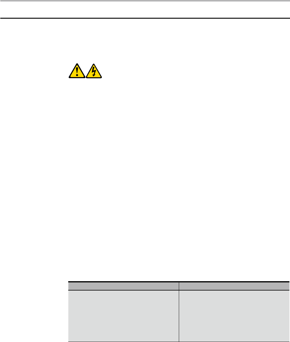
CAUTION:
When replacing the lithium battery, use only Part Number 33F8354 or
an equivalent type battery recommended by the manufacturer. If your
system has a module containing a lithium battery, replace it only with
the same module type made by the same manufacturer. The battery
contains lithium and can explode if not properly used, handled, or
disposed of.
Do not:
Throw or immerse into water •
Heat to more than 100°C (212°F)•
Repair or disassemble•
Dispose of the battery as required by local ordinances or regulations.
CAUTION:
When laser products (such as CD-ROMs, DVD-ROM drives, fiber optic
devices, or transmitters) are installed, note the following:
Do not remove the covers. Removing the covers of the laser product •
could result in exposure to hazardous laser radiation. There are no
serviceable parts inside the device.
Use of controls or adjustments or performance of procedures other •
than those specified herein might result in hazardous radiation
exposure.
DANGER:
Some laser products contain an embedded Class 3A or Class 3B laser
diode. Note the following:
Laser radiation when open. Do not stare into the beam, do not view
directly with optical instruments, and avoid direct exposure to the
beam.
Chapter 2. Safety information
11
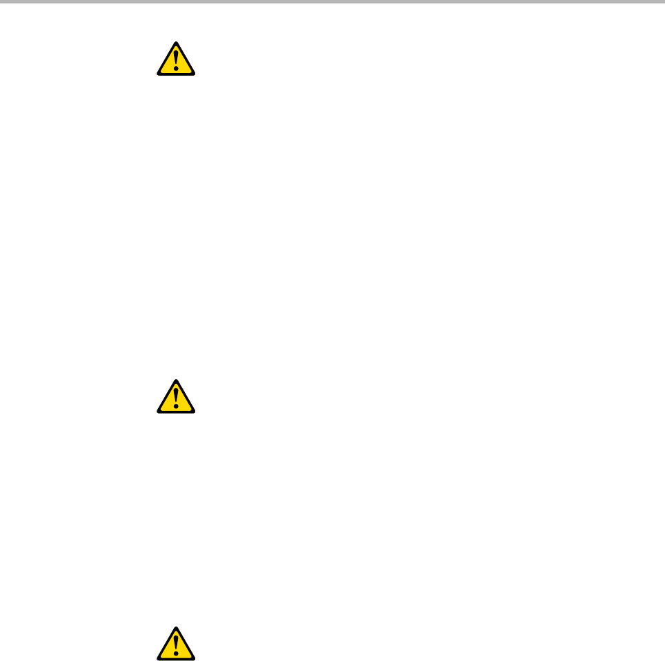
CAUTION:
Use safe practices when lifting.
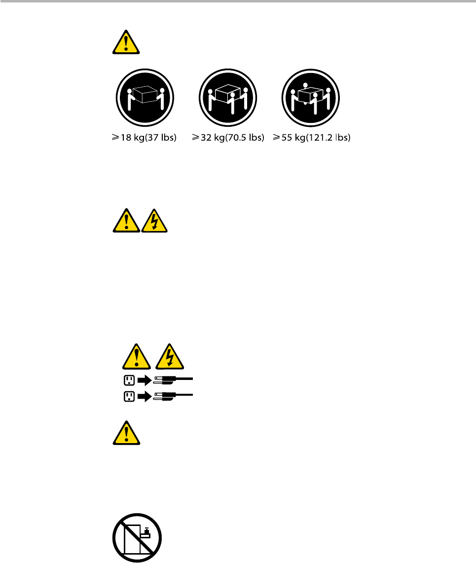
CAUTION:
The power control button on the device and the power switch on the
power supply do not turn off the electrical current supplied to the
device. The device also might have more than one power cord. To
remove all electrical current from the device, ensure that all power cords
are disconnected from the power source.
1
2
CAUTION:
Do not place any object weighing more than 82 kg (180 lbs.) on top of
rack-mounted devices.

Hardware Maintenance Manual
12
General information 3
This chapter provides general information that applies to all machine
types supported by this publication.
Specifications
This section lists the physical specifications for your computer.
Type Lenovo IdeaCentre B5
This section lists the physical specifications.
Environment
Air temperature:
Operating: 10° to 35°C
Transit: -20° to 55°C
Humidity:
Operating: 35% to 80%
Transit: 20% to 93% (40°C)
Altitude: 86KPa to 106KPa
Electrical input
Input voltage: 220V±22V
Input frequency: 50Hz ±1Hz

Chapter 4. General Checkout
13
General Checkout 4
The drives in the computer you are servicing might have been
rearranged or the drive startup sequence changed. Be extremely
careful during write operations such as copying, saving, or
formatting. Data or programs can be overwritten if you select an
incorrect drive.
Attention
General error messages appear if a problem or conflict is found by an
application program, the operating system, or both. For an explanation
of these messages, refer to the information supplied with that software
package.
Notes
• Thedefaultisforthiscomputertobootupinquietmode(nobeep,
no memory count and checkpoint code display) when no errors are
detected by POST.
• Toenablebeep,memorycount,andcheckpointcodedisplaywhen
a successful POST occurs, do the following:
1. Start the Setup Utility program. See “Starting the Setup Utility
program”.
2. Select Start Options.
3. Set Power-On Self-Test to Enhanced.
• BeforereplacinganyFRUs,ensurethatthelatestlevelofBIOSis
installed on the system. A down-level BIOS might cause false errors
and unnecessary replacement of the system board.
Use the following procedure to help determine the cause of the problem:
1. Power-off the computer and all external devices.
2. Check all cables and power cords.
3. Set all display controls to the middle position.
4. Power-on all external devices.

Hardware Maintenance Manual
14
5. Power-on the computer.
• Lookfordisplayederrorcodes
• Listenforbeepcodes
• Lookforreadableinstructionsoramainmenuonthedisplay.
If you did not receive the correct response, proceed to step 6.
If you do receive the correct response, proceed to step 7.
6. Look at the following conditions and follow the instructions:
• IfyouhearbeepcodesduringPOST,goto“Beep symptoms”.
• IfthecomputerdisplaysaPOSTerror,goto“POST error codes”.
• Ifthecomputerhangsandnoerrorisdisplayed,continueatstep7.
7. If you cannot continue, replace the last device tested.
Problem determination tips
Due to the variety of hardware and software combinations that can be
encountered, use the following information to assist you in problem
determination. If possible, have this information available when
requesting assistance from Service Support and Engineering functions.
Machine type and model•
Processor or hard disk upgrades•
Failure symptom •
– Do diagnostics indicate a failure?
– What, when, where, single, or multiple systems?
– Is the failure repeatable?
– Has this configuration ever worked?
– If it has been working, what changes were made prior to it failing?
– Is this the original reported failure?
Diagnostics version •
– Type and version level
Hardware configuration •
– Print (print screen) configuration currently in use
– BIOS level
Operating system software •
– Type and version level
Note: To eliminate confusion, identical systems are considered identical
only if they:
1. Are the exact machine type and models
2. Have the same BIOS level
3. Have the same adapters/attachments in the same locations
4. Have the same address jumpers/terminators/cabling
5. Have the same software versions and levels
6. Have the same configuration options set in the system
7. Have the same setup for the operation system control files

Chapter 4. General Checkout
15
Comparing the configuration and software set-up between
“working and non-working” systems will often lead to problem
resolution.

Hardware Maintenance Manual
16
Using the Setup Utility 5
The Setup Utility program is used to view and change the configuration
settings of your computer, regardless of which operating system you are
using. However, the operating-system settings might override any similar
settings in the Setup Utility program.
Starting the Setup Utility program
To start the Setup Utility program, do the following:
1. If your computer is already on when you start this procedure, shut
down the operating system and turn off the computer.
2. Press and hold the F1 key then turn on the computer. When you hear
multiple beeps, release the F1 key.
Notes:
a. If you are using a USB keyboard and the Setup Utility program does
not display using this method, repeatedly press and release the F1
key rather than leaving it pressed when turning on the computer.
b. If a Power-On Password or an administrator password has been set,
the Setup Utility program menu is not displayed until you type your
password. For more information, see “Using passwords.”
Viewing and changing settings
The Setup Utility program menu lists items that identify system
configuration topics. To view or change settings, see “Starting the Setup
Utility program.”
When working with the Setup Utility program menu, you must use the
keyboard. The keys used to perform various tasks are displayed on the
right side of each screen.

Chapter 5. Using the Setup Utility
17
Using passwords
By using the Setup Utility program, you can set passwords to prevent
unauthorized persons from gaining access to your computer and data.
See “Starting the Setup Utility program.” The following types of passwords
are available:
• AdministratorPassword
• Power-OnPassword
You do not have to set any passwords to use your computer. However, if
you decide to set any passwords, read the following sections.
Password considerations
A password can be any combination of up to 64 characters (a-z and
0-9) and symbols. For security reasons, it is a good idea to use a strong
password that cannot be easily compromised. We suggest the passwords
should adhere to the following rules:
• Musthaveatleastsevencharactersinlength
• Containatleastonealphabeticcharacterandonenumericcharacter
• SetupUtilityprogramandharddiskdrivepasswordsarenotcase
sensitive
• Notbeyournameoryourusername
• Notbeacommonwordoracommonname
• Besignicantlydierentfromyourpreviouspassword
Administrator password
When a Administrator Password is set, it deters unauthorized persons from
changing configuration settings. If you are responsible for maintaining
the settings of several computers, you might want to set a Administrator
Password.
After you set a Administrator Password, a password prompt is displayed
each time you try to access the Setup Utility program.
If both the Administrator and Power-On Password are set, you can type
either password. However, to change any configuration settings, you must
use your Administrator password.

Hardware Maintenance Manual
18
Setting, changing, and deleting a Administrator password
To set, change, or delete a password, do the following:
Note
A password can be any combination of up to 64 characters (a-z, and
0-9). For more information, see “Password considerations” on page 17.
1. Start the Setup Utility program (see “Starting the Setup Utility program”
on page 16).
2. From Security menu, select Set Administrator Password and press
Enter.
3. The password dialog box will be displayed. Type the new password,
and press Enter.
4. when prompted to confirm the password, type the password again. If
you type the password correctly, the password will be installed.
To delete a previously set Administrator password, do the following :
Note: When prompted for a password, you must type your Administrator
password.
1. From Security menu, select Set Administrator Password and press
Enter.
2. The password dialog box will be displayed. Enter Current Password and
press Enter. Press Enter in New Password and confirm New Password
dialog. A setup notice will display that changes have been saved.
3. Select Exit.
4. Select Save changes and Exit.
Power-On Password
When a Power-On Password is set, you cannot start the Setup Utility
program until a valid password is typed from the keyboard.
Setting, changing, and deleting a Power-On Password
To set, change, or delete a Power-On Password, do the following:
Note
A password can be any combination of up to 64 characters(a-z, and
0-9).
1. Start the Setup Utility program (See ”Starting the Setup Utility program”.)
2. From the Security menu, selet Set Power-On Password and press Enter.

Chapter 5. Using the Setup Utility
19
3. The password dialog box will be displayed. Type the new password, and
press Enter.
4. when prompted to confirm the password, type the password again. If
you type the password correctly, the password will be installed.
To delete a previously set Power-On Password, do the following :
1. From the Security menu, select Set Power-On Password and press
Enter.
2. The password dialog box will be displayed. Enter Current Password and
press Enter. Press Enter in New Password and confirm New Password
dialog. A setup notice will display that changes have been saved.
3. Select Exit.
4. Select Save changes and Exit.
After the password is set, you may select the “Advanced” Menu for device setup.
Using Device
Device is used to enable or disable user access to the following device
USB Setup When this feature is set to Disable,
the device of USB Setup is
disabled and will not be displayed in
the system configuration.
To set Device, do the following:
1. Start the Setup Utility program (see “Starting the Setup Utility program”
on page 16).
2. From the Setup Utility program menu, select Devices.
3. Select USB Setup.
4. Select Disabled or Enabled and press Enter.
5. Return to the Setup Utility program menu and press F10 to save
configuration changes and exit setup.
Note
If you do not want to save the settings, select Exit and select Discard
changes and Exit.You can set others such as Audio Setup and
Network Setup. See the information displayed on the right side of
the screen.

Hardware Maintenance Manual
20
Selecting a startup device
If your computer does not start up (boot) from a device such as the
CD-ROM, diskette, or hard disk as expected, use one of the following
procedures to select a startup device.
Selecting a temporary startup device
Use this procedure to startup from any boot device.
Note: Not all CDs, hard disks, and diskettes are bootable.
1. Turn off your computer.
2. Press and hold the F12 key then turn on the computer. When the
Startup Device Menu appears, release the F12 key.
Note: If you are using a USB keyboard and the Startup Device Menu
does not display using this method, repeatedly press and release
the F12 key rather than leaving it pressed when turning on the
computer.
3. Select the desired startup device from the Startup Device Menu and
press Enter to begin.
Note: Selecting a startup device from the Startup Device menu does
not permanently change the startup sequence.
Selecting or changing the startup device sequence
To view or permanently change the configured startup device sequence,
do the following:
1. Start the Setup Utility program (see “Starting the Setup Utility program”
on page 16).
2. Select Start Up.
3. Select Quick Boot Mode, Numlock, Option Keys Display, Option Keys
Display Style or Startup Device Menu Prompt to set these devices.
4. Select Disabled or Enabled and press Enter.
5. Press ESC to return to Exit and select Save changes and Exit.
If you have changed these settings and want to return to the default
settings, select Load Optimal Defaults on the Setup Utility menu.

Chapter 5. Using the Setup Utility
21
Exiting from the Setup Utility program
When you finish viewing or changing settings, press Esc to return to the
Setup Utility program menu (you might have to press Esc several times).
If you want to save the new settings, select Save changes and Exit before
you exit. Otherwise, your changes will not be saved.
Hardware Maintenance Manual
22
Symptom-to-FRU Index 6
The Symptom-to-FRU index lists error symptoms and possible causes.
The most likely cause is listed first. Always begin with Chapter 4, “General
Checkout,” on page 13. This index can also be used to help you decide
which FRUs to have available when servicing a computer. If you are unable
to correct the problem using this index, go to “Undetermined problems”
on page 27.
Notes
• Ifyouhavebothanerrormessageandanincorrectaudioresponse
diagnose the error message first.
• Ifyoucannotrunthediagnostictestsoryougetadiagnosticerror
code when running a test but did receive a POST error message
diagnose the POST error message first.
• Ifyoudidnotreceiveanyerrormessagelookforadescriptionof
your error symptoms in the first part of this index.
Hard disk drive boot error
A hard disk drive boot error (error codes 1962 and I999030X) can have the
following causes.
Error FRU/Action
The start-up drive is not in the boot
sequence in configuration.
Check the configuration and ensure
the start-up drive is in the boot
sequence.
No operating system installed on
the boot drive.
Install an operating system on the
boot drive.
Chapter 6. Symptom-to-FRU Index
23
Error FRU/Action
The boot sector on the start-up
drive is corrupted.
The drive must be formatted do the
following:
1. Attempt to back-up the data on
the failing hard disk drive.
2. Using the operating systems
programs format the hard disk
drive.
The drive is defective. Replace the hard disk drive.
Power Supply Problems
If you suspect a power problem, use the following procedures.
Check/Verify FRU/Action
Check the following for proper
installation.
Power Cord•
On/Off Switch connector•
On/Off Switch Power Supply •
connector
System Board Power Supply •
connectors
Microprocessor(s) connection•
Reseat connectors
Check the power cord for continuity. Power Cord
Check the power-on switch for
continuity.
Power-on Switch
Hardware Maintenance Manual
24
Beep symptoms
Beep symptoms are tones or a series of tones separated by pauses
(intervals without sound) during POST.
The following tables describes beep symptoms.
Beep Symptom FRU/Action
1 beep
Memory refresh timer error
Reseat the memory, or replace with
known good modules.
2 beeps
Parity error in base memory (first
64KB block)
3 beeps
Base memory read/write test error
POST error codes
Each time you power-on the system, it performs a series of tests that
check the operation of the system and some options. This series of tests is
called the Power-On Self-Test, or POST. POST does the following operations.
• Checkssomebasicsystem-boardoperations
• Checksthememoryoperation
• Startsthevideooperation
• Veriesthatthebootdriveisworking
If the POST detects a problem, an error message appears on the screen.
A single problem can cause several error messages to appear. When you
correct the cause of the first error message, the other error messages
probably will not appear on the screen the next time you turn on the
system.

Chapter 6. Symptom-to-FRU Index
25
POST Error Message Description/Action
CMOS Date/Time Not Set The CMOS Date and/or Time are
invalid. This error can be resolved
by readjusting the system time in
Phenix BIOS Setup.
CMOS Battery Low The CMOS battery is no longer
functional.
Replace the battery.
CMOS Checksum Bad Checksum of CMOS is incorrect.
The computer loads the default
configuration settings. This error
might indicate that CMOS has
become corrupt due to a weak
CMOS battery.
Primary Master Hard Disk Error The IDE/ATAPI device configured
as Primary Master/Primary Slave/
Secondary Master/Secondary Slave
could not be found or initialized.
Make sure the hard drive is correctly
installed.
Primary Slave Hard Disk Error
Secondary Master Hard Disk Error
Secondary Slave Hard Disk Error
Keyboard error Cannot initialize the keyboard.
Make sure the keyboard is properly
connected to the computer and
that no keys are held pressed during
POST.
To purposely configure the
computer without a keyboard, set
keyboardless operation in Setup to
Enable. The BIOS then ignores the
missing keyboard during POST.
System Halted The system has been halted. A reset
or power cycle is required to reboot
the machine. This message appears
after a fatal error has been detected.
Reboot and Select proper Boot
device or Insert Boot Media in
selected Boot device
The BIOS was unable to find a
suitable boot device.
Make sure the boot drive is properly
connected to the computer.
Make sure you have bootable
media.

Hardware Maintenance Manual
26
Undetermined problems
If this computer has a parallel ATA hard disk drive, make sure that the hard
disk drive is jumpered as a master and the optical drive is jumpered as a
slave.
1. Power-off the computer.
2. Remove or disconnect the following components (if installed) one at a
time.
a. External devices (modem, printer, or mouse)
b. Any adapters
c. Memory modules
d. Extended video memory
e. External Cache
f. External Cache RAM
g. Hard disk drive
h. Diskette drive
3. Power-on the computer to re-test the system.
4. Repeat steps 1 through 3 until you find the failing device or adapter.
If all devices and adapters have been removed, and the problem
continues, replace the system board.
Chapter 7. Locations
27
Locations 7
This section provides illustrations to help locate the various connectors,
controls and components of the computer. To remove the computer
cover, “refer to Removing the computer cover” .
Locating components and connectors
The following illustrations will help you to locate the various components
and connectors in your computer.
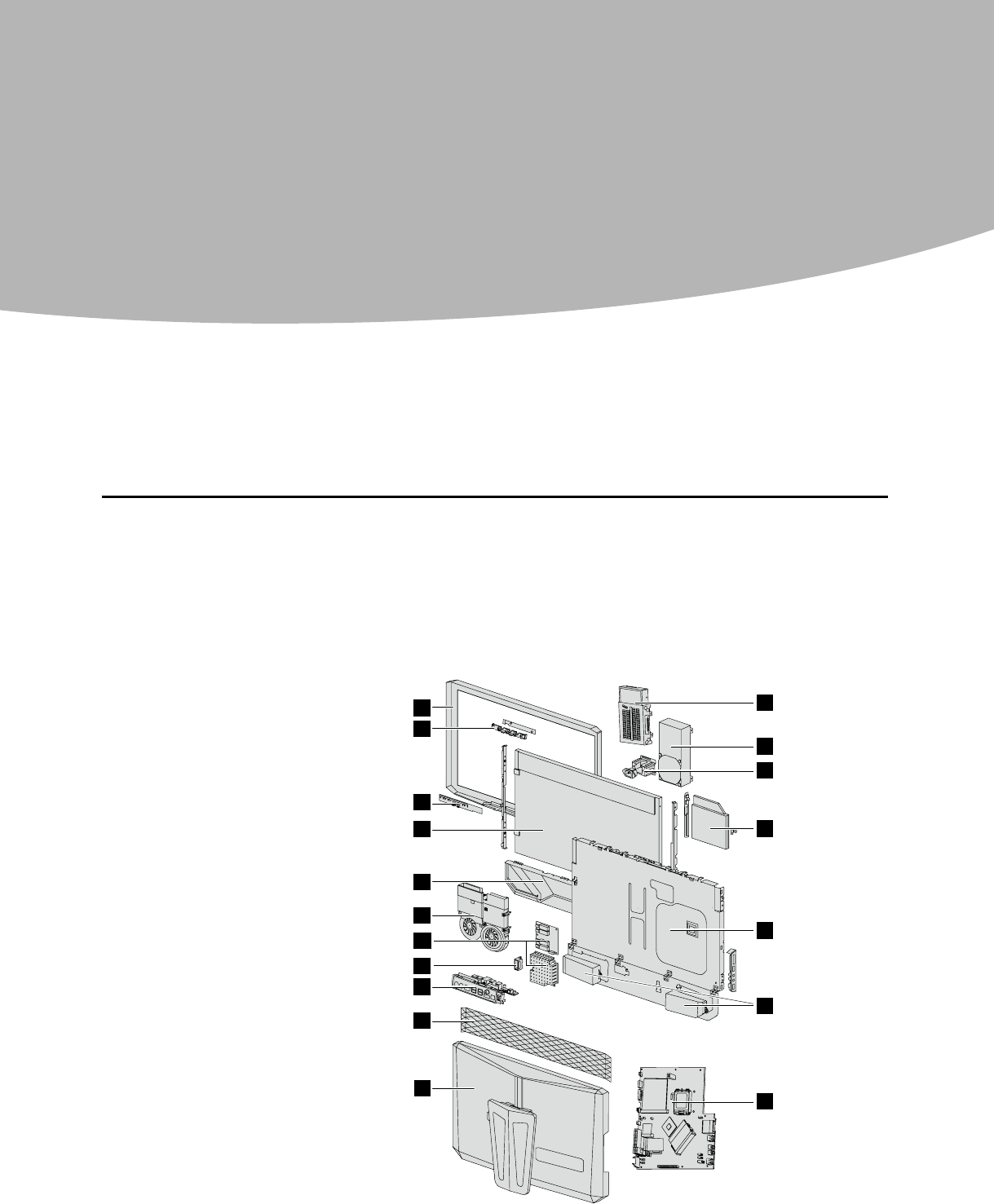
Internal components
The following illustration shows the components inside your computer.
1
2
3
4
5
6
9
8
7
10
11
12
13
14
15
16
17
18
1. LCD front bezel
2. Camera module
3. Touch pad module
4. LCD panel
5. Speaker bezel
6. Thermal module
7. Inverter board and shield
8. Power switch
9. Rear IO
10. LCD back bezel
11. Back cover
12. System board
13. Speaker sets
14. Chassis
15. Optical drive
16. Power inlet
17. Power supply
18. Hard disk drive

Hardware Maintenance Manual
28
1
LCD front bezel
2
Camera module
3
Touch pad module
4
LCD panel
5
Speaker bezel
6
Thermal module
7
Inverter board and shield
8
Power switch
9
Rear IO
10
LCD back bezel
11
Back cover
12
System board
13
Speaker sets
14
Chassis
15
Optical drive
16
Power inlet
17
Power supply
18
Hard disk drive
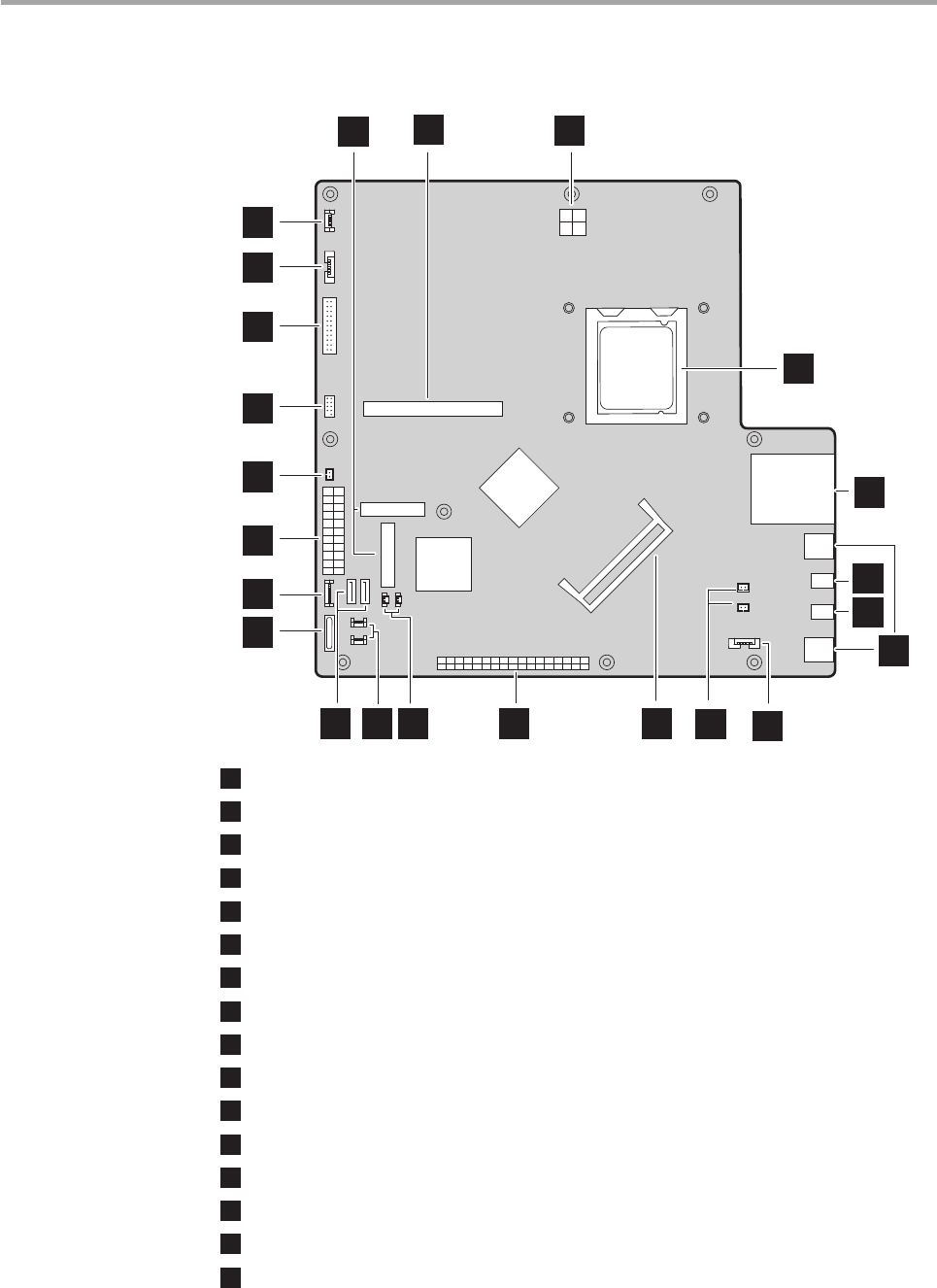
Identifying parts on the system board
The system board (sometimes called the planar or motherboard) is the
main circuit board in your computer. It provides basic computer functions
and supports a variety of devices that are factory-installed or that you can
install later.
The following illustration shows the locations of parts on the system
board.
Chapter 7. Locations
29
Front view of the system board
2
3
4
1
5
10 11 12 13 14 15
16
17
18
19
20
21
22
23
8
9
7
6
1
Camera cable connector
2
Inverter board cable connector
3
Onboard LVDS
4
Side panel connector
5
Front LED connector
6
Power connector
7
Front touch board cable connector
8
Battery socket
9
SATA connectors (2)
10
Bluetooth and RF connectors
11
MXM fan cable and CPU fan cable connectors
12
Rear I/O board connector
13
Memory slots
14
Right and left speakers LED
15
Speakers cable connector
16
USB connectors (2)

Hardware Maintenance Manual
30
17
Microphone connector
18
Headphone connector
19
Card Reader
20
CPU socket
21
12V power connector
22
MXM graphic card connector
23
TV tuner card and WLAN card connectors
Chapter 8. Replacing hardware
31
Replacing hardware 8
Attention
Do not remove the computer cover or attempt any repair before
reading the “Important safety information” in the Safety and Warranty
Guide that was included with your computer or in the Hardware
Maintenance Manual (HMM) for the computer. To obtain copies of
the Safety and Warranty Guide or HMM, go to the Support Web site at:
http://consumersupport.lenovo.com.
Note
Use only parts provided by Lenovo.
General information
Pre-disassembly instructions
Before proceeding with the disassembly procedure, make sure that you
do the following:
1. Turn off the power to the system and all peripherals.
2. Unplug all power and signal cables from the computer.
3. Place the system on a flat, stable surface.
Hardware Maintenance Manual
32
Removing the computer cover
Attention
Turn off the computer and wait 3 to 5 minutes to let the computer
cool before removing the computer cover.
To remove the computer cover:
Note
For this procedure, it helps to place the computer face-down on a
soft flat surface. Lenovo recommends that you use a blanket, towel,
or other soft cloth to protect the screen surface from scratches or
other damage.
1. Remove any media (diskettes, CDs, or memory cards) from the drives,
shut down your operating system, turn off all attached devices, and
the computer.
2. Unplug all power cords from electrical outlets.
3. Disconnect all cables attached to the computer. This includes power
cords, input/output (I/O) cables, and any other cables that are
connected to the computer. Refer to “Locating connectors on the rear
of the computer.”
4. Place the computer upside down on the flat surface. Remove the eight
rubber caps covering the screws on the system cover.
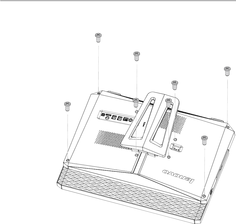
Chapter 8. Replacing hardware
33
5. Remove the eight screws that secure the computer back cover to
chassis.
Hardware Maintenance Manual
34
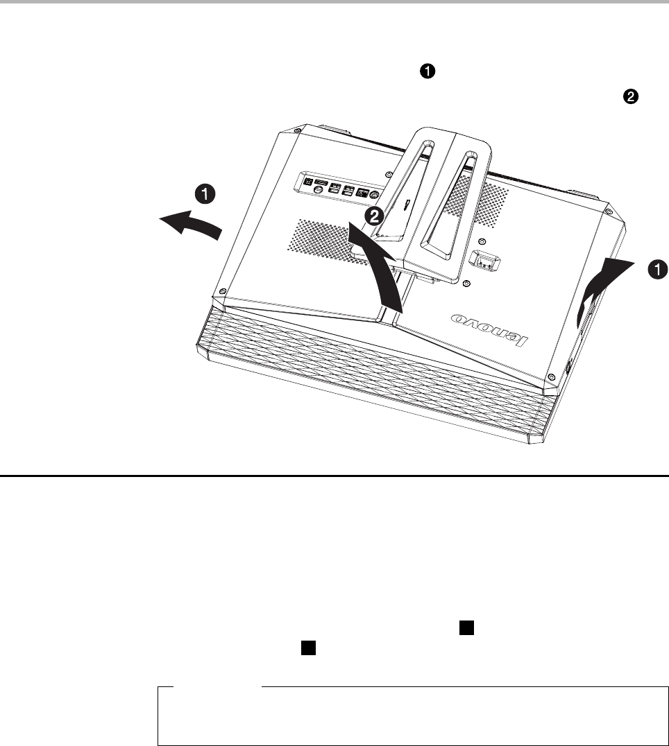
6. Release the left and right tabs from the connector housing, then pull
each side of the cover out slightly , release the top tabs from the
connector housing, then lift the cover away from the computer .
Replacing the power supply
To replace the power supply
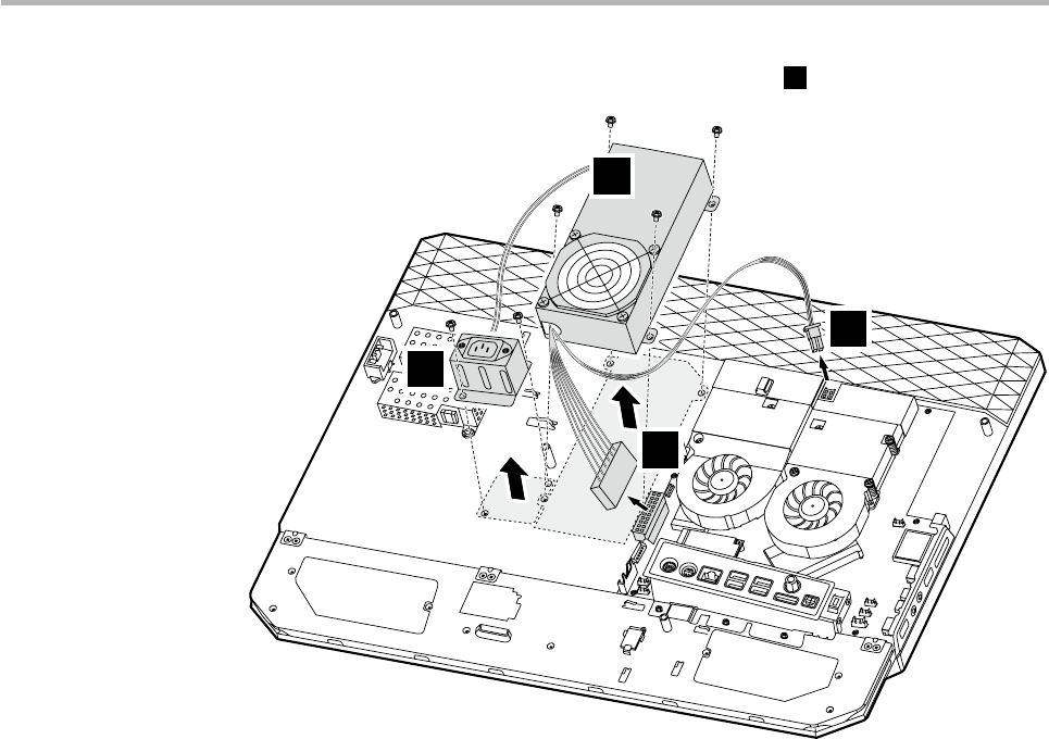
1. Remove the power supply module.
1) Remove the two screws that secure the AC inlet to the computer
chassis.
2) Remove the AC inlet from the chassis
1
. Disconnect all power
supply cables
2
from the drives and system board.
Important
Note the cable routing. It is important to route the cables the same
way after you install the new power supply.
3) Remove the four screws that secure the power supply to the
computer chassis.
Chapter 8. Replacing hardware
35
4) Remove the power supply from the chassis
3
.
3
1
2
2
2. Align the screw holes on the new power supply to the mounting holes
on the computer chassis.
3. Screw back the four screws on the new power supply.
4. Reconnect all the power supply cables to the drives and the system
board.
5. Align the screw holes on the AC inlet to the mounting holes on the
computer chassis.
6. Screw back the two screws on the AC inlet.
7. Screw back the computer back cover to the computer chassis.
Hardware Maintenance Manual
36
Replacing the hard disk drive
To replace the hard disk drive
1. Remove the computer cover. Refer to “Removing the computer cover.”
2. Disconnect the data and power cables from the hard disk drive.
Remove the two screws that secure the hard disk drive to the chassis.
Pull out the hard disk drive from the chassis.
3. Remove the four screws that secure the hard disk drive to the drive
bay. Slide the hard disk drive out of the drive bay.
Chapter 8. Replacing hardware
37
4. Install the new hard disk drive.
(1.)Insert the new hard disk drive into the drive bay.
(2.) Screw back the four screws on the drive bay.
5. Screw back the hard disk drive bay back to the chassis.
6. Connect the data and power cables back to the hard disk drive.
7. Screw back the computer back cover to the computer chassis.
Replacing an optical drive
To replace an optical drive
1. Remove the computer cover. Refer to “Removing the computer cover.”
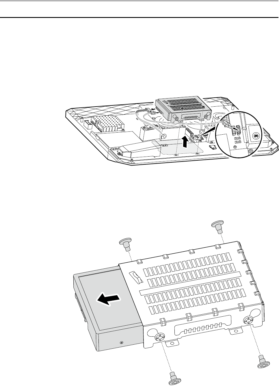
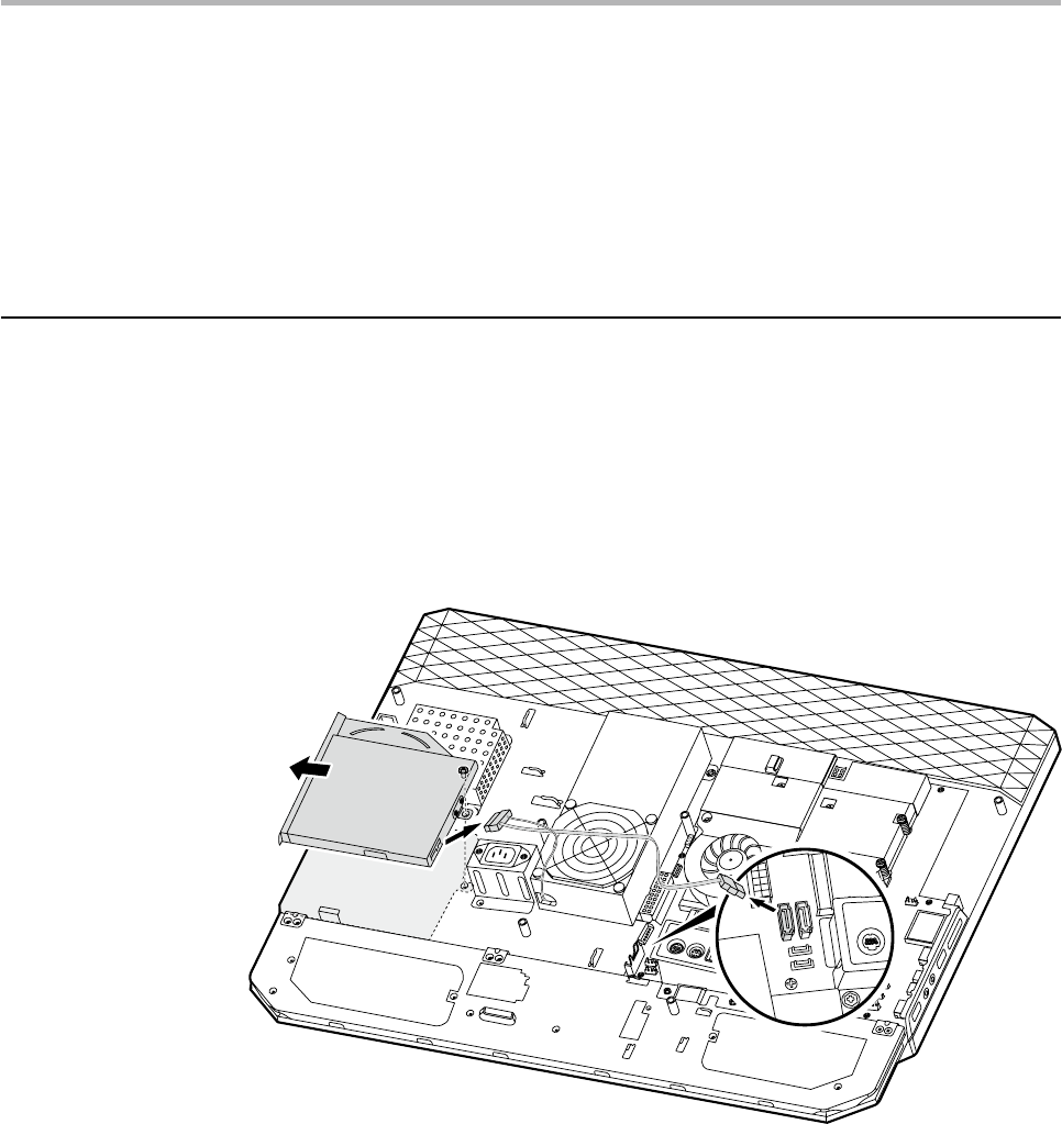
2. Remove the screw that secures the optical drive to the chassis.
Disconnect one end of the ODD data and power cables from the rear
of the optical drive. Slide the optical drive out of the drive bay.
Hardware Maintenance Manual
38
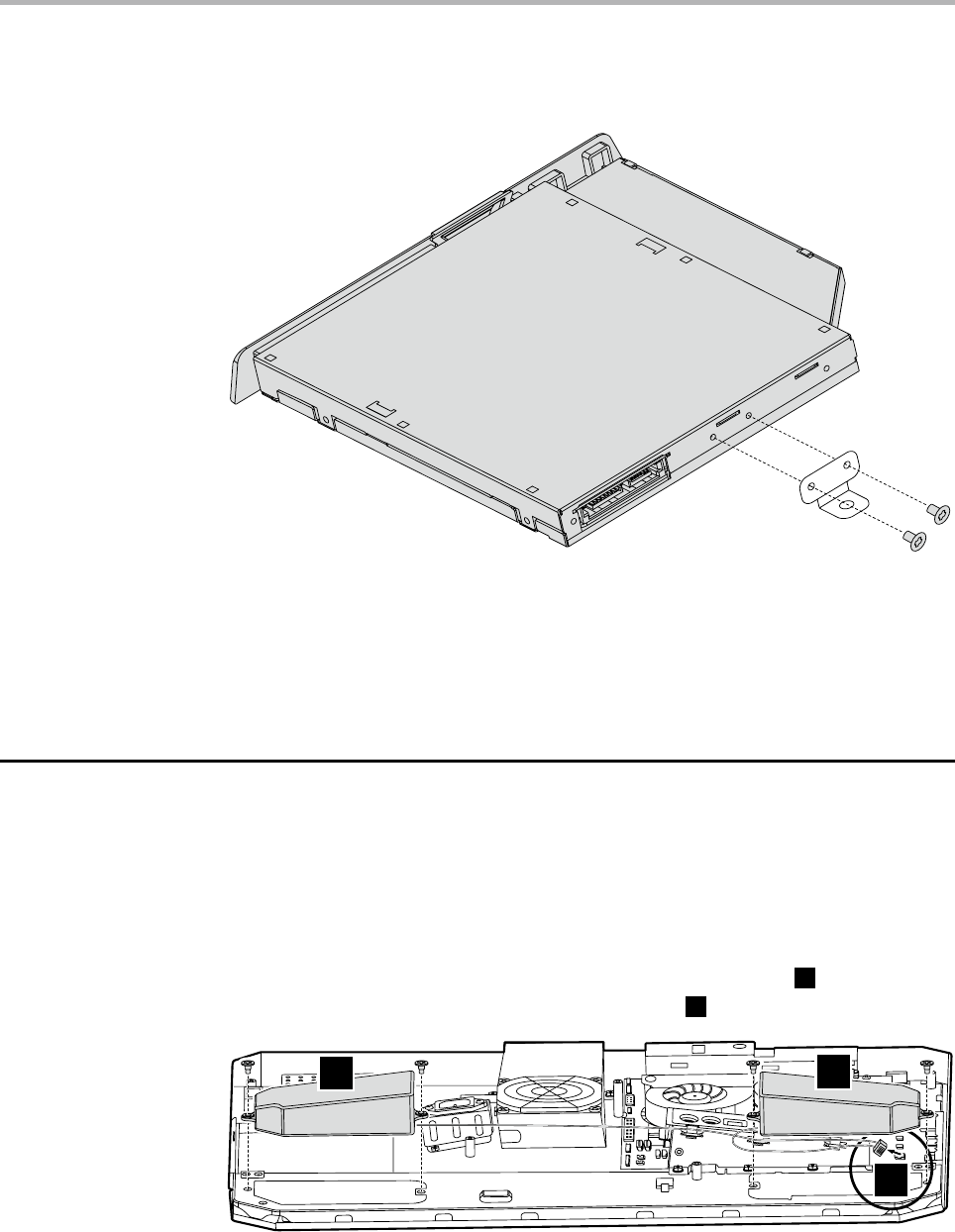
3. Remove the two screws that secure the optical drive to the metal
bracket.
4. Screw back the metal bracket to the new optical drive.
5. Slide the new optical drive into the drive bay and screw the optical
drive back to the chassis.
6. Connect the ODD data and power cables to the optical drive.
7. Screw back the computer back cover to the computer chassis.
Replace the speakers system
To replace the speakers system
1. Remove the computer cover. Refer to “Removing the computer cover”.
2. Remove the four screws that secure the left and right speakers to the
chassis.
3. Disconnect the speakers’ cable from the system board
2
, and pull out
the left and right speakers from the chassis
1
.
11
2
Chapter 8. Replacing hardware
39
4. Align then insert the new speakers to the chassis.
5. Screw back the computer back cover to the computer chassis.
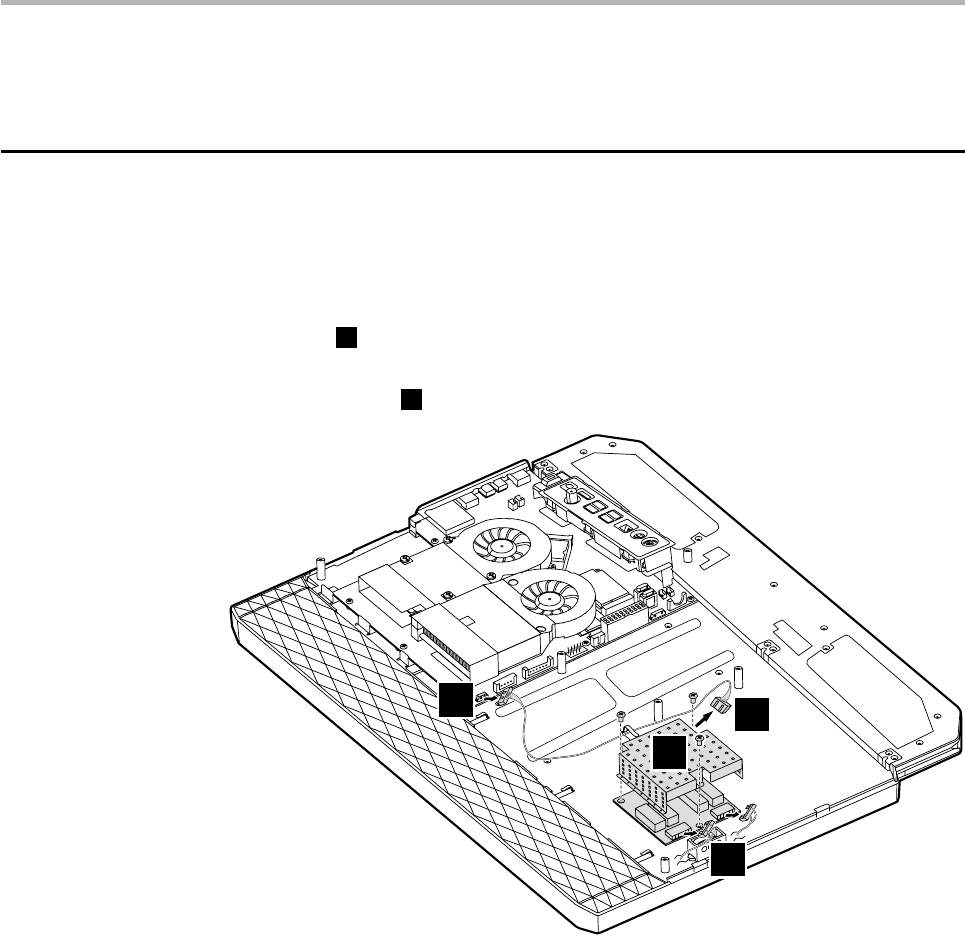
Replace the Inverter board
To replace the inverter board
1. Remove the computer cover. Refer to “Removing the computer cover”.
2. Remove the three screws that secure the inverter board shield to the
chassis
1
.
3. Disconnect the inverter board cables from the inverter board and
system board
2
. Pull the inverter board away from the chassis.
1
2
2
2
4. Align then insert the new inverter board to the chassis.
5. Connect the inverter board cables to the inverter board.
6. Screw back the shield on the inverter board.
7. Screw back the computer back cover to the computer chassis.
Hardware Maintenance Manual
40
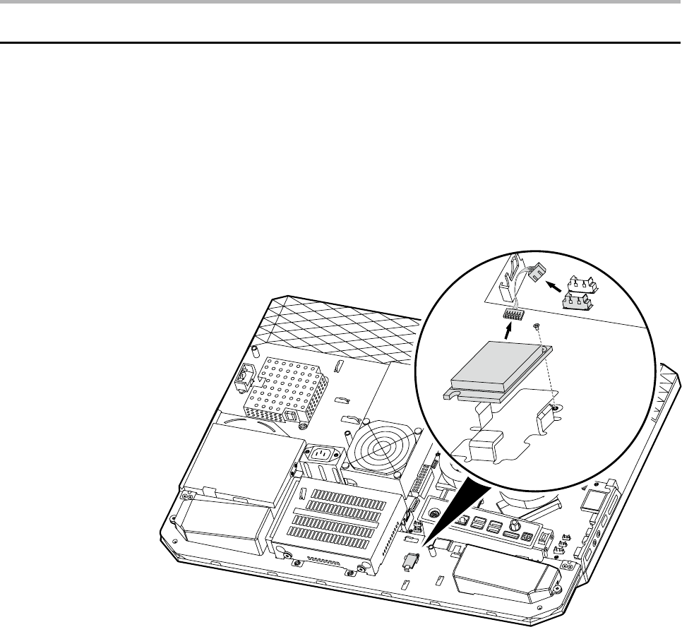
Replacing the Bluetooth module
To replace the Bluetooth module
1. Remove the computer cover. Refer to “Removing the computer cover”.
2. Disconnect the Bluetooth module cable from the Bluetooth module
and system board.
3. Remove the screw that secures the Bluetooth module to the chassis.
4. Pull the Bluetooth module away from the chassis.
5. Connect the Bluetooth cable to the new Bluetooth module.
6. Align then screw the new Bluetooth module to the chassis.
7. Screw back the computer back cover to the computer chassis.
Chapter 8. Replacing hardware
41
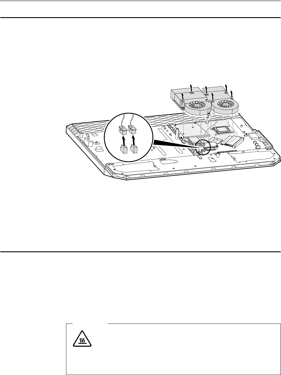
Replacing the thermal module
To replace the thermal module
1. Remove the computer cover. Refer to “Removing the computer cover”.
2. Disconnect all the thermal module cables from the system board.
3. Remove the 7 screws that secure the thermal module to the chassis.
4. Pull the thermal module away from the chassis.
5. Align the 7 screw holes on the new thermal module to the 7 mounting
holes on the chassis.
6. Insert and tighten the 7 screws to secure the thermal module.
7. Connect the thermal module cables to the system board.
8. Screw back the computer back cover to the computer chassis.
Replacing the CPU
To replace the CPU
1. Remove the computer cover. Refer to “Removing the computer cover”.
2. Remove the thermal module. Refer to “Replacing the thermal module”.
3. Lift the small handle and open the retainer.
Attention
Do not touch the gold contacts on the bottom of the microprocessor.
When handing the microprocessor, touch only the sides.
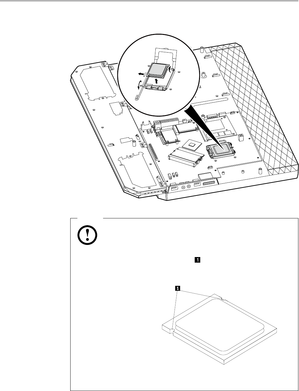
Hardware Maintenance Manual
42
4. Lift the microprocessor straight up and out of the socket.
Notes
a. Note the orientation of the notches on the microprocessor. This
is important when reinstalling the new microprocessor on the
motherboard.
b. Do not drop anything onto the microprocessor socket while it is
exposed. The socket pins must be kept as clean as possible.
5. Make sure that the microprocessor retainer is fully open.
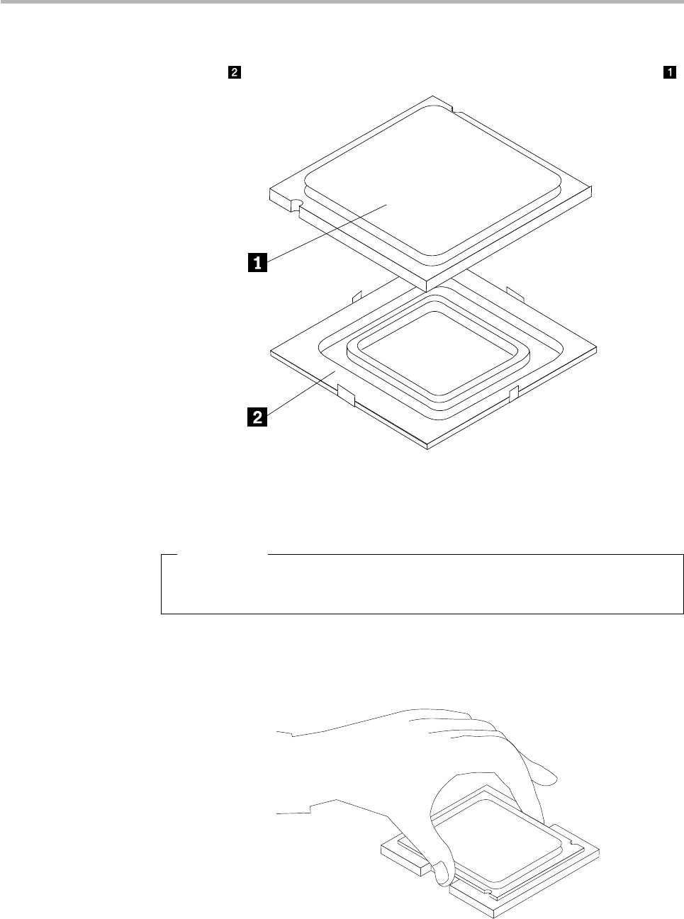
Chapter 8. Replacing hardware
43
6. Holding the microprocessor with your fingers, remove the protective
cover that protects the gold contacts on the new microprocessor .
7. Holding the microprocessor with your fingers, position the
microprocessor so that the notches on the microprocessor are aligned
with the tabs in the microprocessor socket.
Important
To avoid damaging the microprocessor contacts, do not tilt the
microprocessor when installing it into the socket.
8. Lower the microprocessor straight down into its socket on the
motherboard.
Hardware Maintenance Manual
44
9. To secure the microprocessor in the socket, close the microprocessor
retainer and lock it into position with the small handle.
10. Use the thermal grease syringe to place five drops of grease on the top
of the microprocessor. Each drop of grease should be 0.03ml (3 tick
marks on the grease syringe).
11. Install the thermal module.
12. Screw back the computer back cover to the computer chassis.
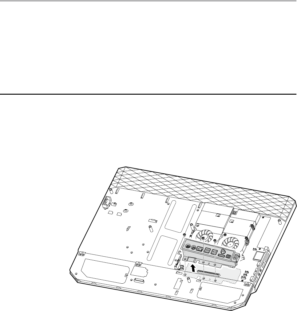
Replacing the Rear IO module
To replace the rear IO module
1. Remove the computer cover. Refer to “Removing the computer cover”.
2. Remove the three screws that secure the rear IO to the chassis. Pull the
rear IO away from the chassis.
3. Align and screw a new rear IO back to the chassis.
4. Screw back the computer back cover to the computer chassis.
Chapter 8. Replacing hardware
45
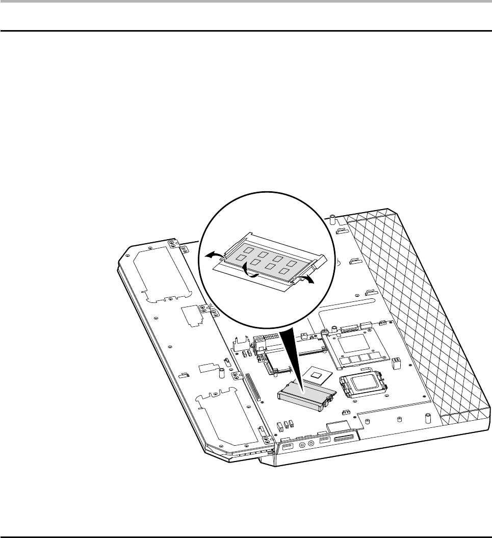
Replacing a memory module
To replace a memory module
1. Remove the computer cover. Refer to “Removing the computer cover”.
2. Remove the thermal module. Refer to “Replacing the thermal module”.
3. Push out the latches on both sides of the memory socket to release
the memory module and gently pull the memory module upward to
remove it from its socket. Both memory modules can be removed by
using the same procedure.
4. Align then insert the new memory module into the socket and push
down on the top edge of the memory module. Make sure the latches
lock the memory module in place.
Replacing the MXM graphic card
To replace the MXM graphic card
1. Remove the computer cover. Refer to “Removing the computer cover”.
2. Remove the thermal module. Refer to “Replacing the thermal module”.
3. Remove the two screws that secure the MXM graphic card to the
chassis.
Hardware Maintenance Manual
46
4. Detach the MXM graphic card from the MXM power connector.
5. Align then insert the new MXM graphic card to the MXM power
connector.
6. Screw back the two screws on the MXM graphic card.
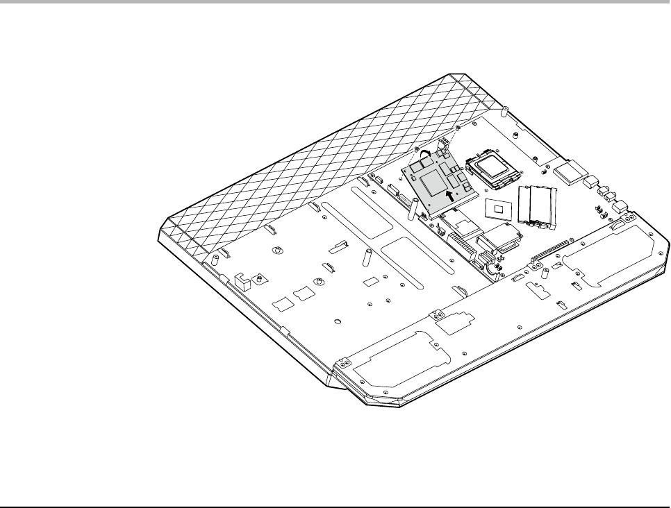
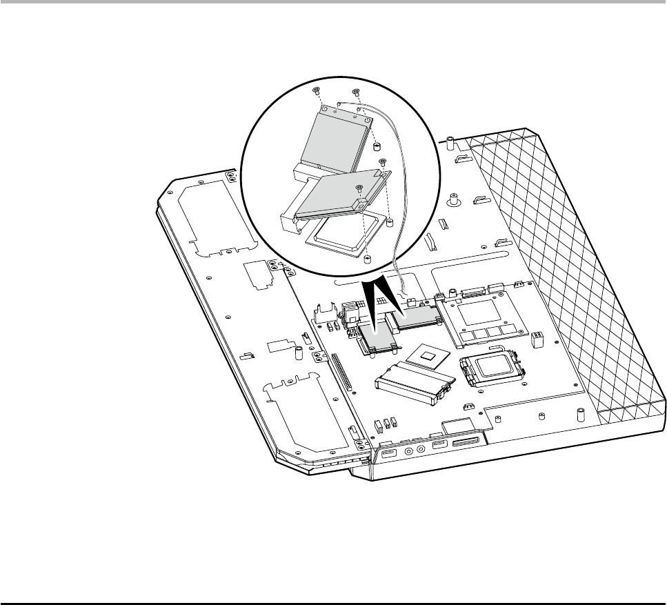
Replacing the TV tuner card and wireless card
To replace the TV tuner card and wireless card
1. Remove the computer cover. Refer to “Removing the computer cover”.
2. Remove the thermal module. Refer to “Replacing the thermal module”.
3. Remove the rear IO module. Refer to “Replacing the rear IO module”.
4. Disconnect the antenna cables from the TV tuner card and wireless
card.
5. Remove the four screws that secure the TV tuner card and wireless
card to the system board.
Chapter 8. Replacing hardware
47
6. Detach the two cards from the card ports.
7. Align then insert the new TV tuner card and wireless card to the card
ports.
8. Screw back the two new cards.
9. Connect the antenna cables back to the two new cards.
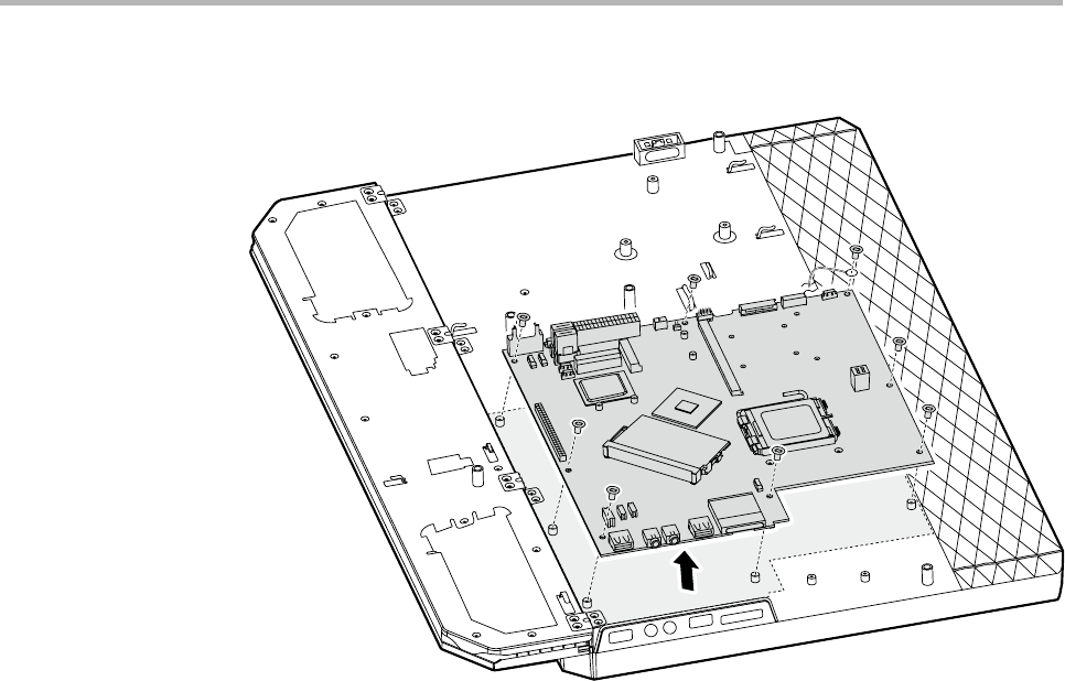
Replacing the system board
To replace the system board
1. Remove the computer cover. Refer to “Removing the computer cover”.
2. Remove the thermal module. Refer to “Replacing the thermal module”.
3. Remove the CPU. Refer to “Replacing the CPU”.
4. Remove the rear IO module. Refer to “Replacing the rear IO module”.
5. Remove the memory module. Refer to “Replacing the memory module”.
6. Remove the MXM graphic card. Refer to “Replacing the MXM graphic
card”.
7. Remove the TV tuner card and wireless card. Refer to “Replacing the TV
tuner card and wireless card”.
8. Remove the 8 screws that secure the system board to the chassis.
Hardware Maintenance Manual
48
9. Pull the system board out of the chassis.
10. Place the new motherboard into the chassis, aligning the screw holes
in the motherboard with the mounting holes in the chassis.
11. Screw the 8 screws on the new motherboard back in.
12. Install all related components back to the new motherboard.
13. Install the computer cover.
Chapter 8. Replacing hardware
49
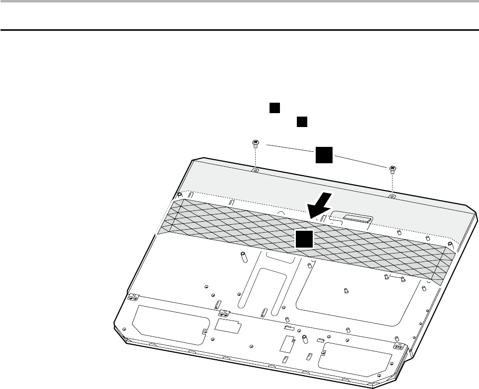
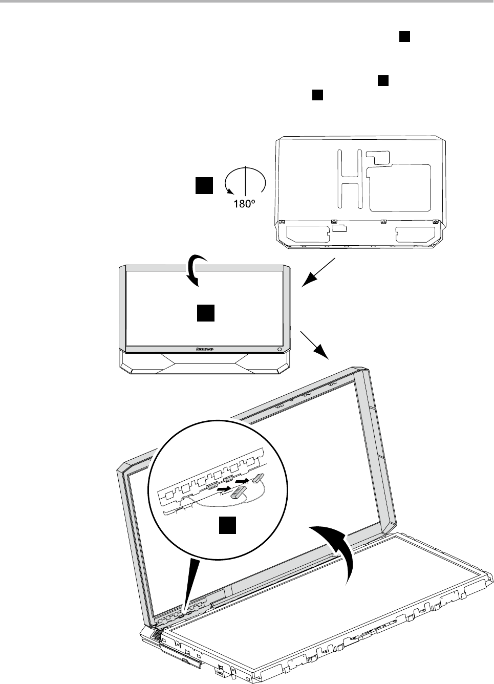
Replacing the touch sensor board
To replace the touch sensor board
1. Remove the computer cover. Refer to “Removing the computer cover”.
2. Remove the LCD back bezel
1
and remove the two screws that secure
the LCD front bezel to the chassis
2
.
1
2
Hardware Maintenance Manual
50
3. Place the computer upside down on the flat surface
3
. Release the
left and right tabs from the connector housing, then pull each side of
the cover out slightly, release the top tabs from the connector housing,
then lift the LCD bezel away from the computer
4
. Disconnect the
cable from the touch sensor board
5
and remove the insulating tape
on touch sensor board.
3
4
5
Chapter 8. Replacing hardware
51
4. Stick a new touch sensor board to the LCD bezel with the insulating
tape.
5. Connect the cable to the touch sensor board.
6. Install the computer.
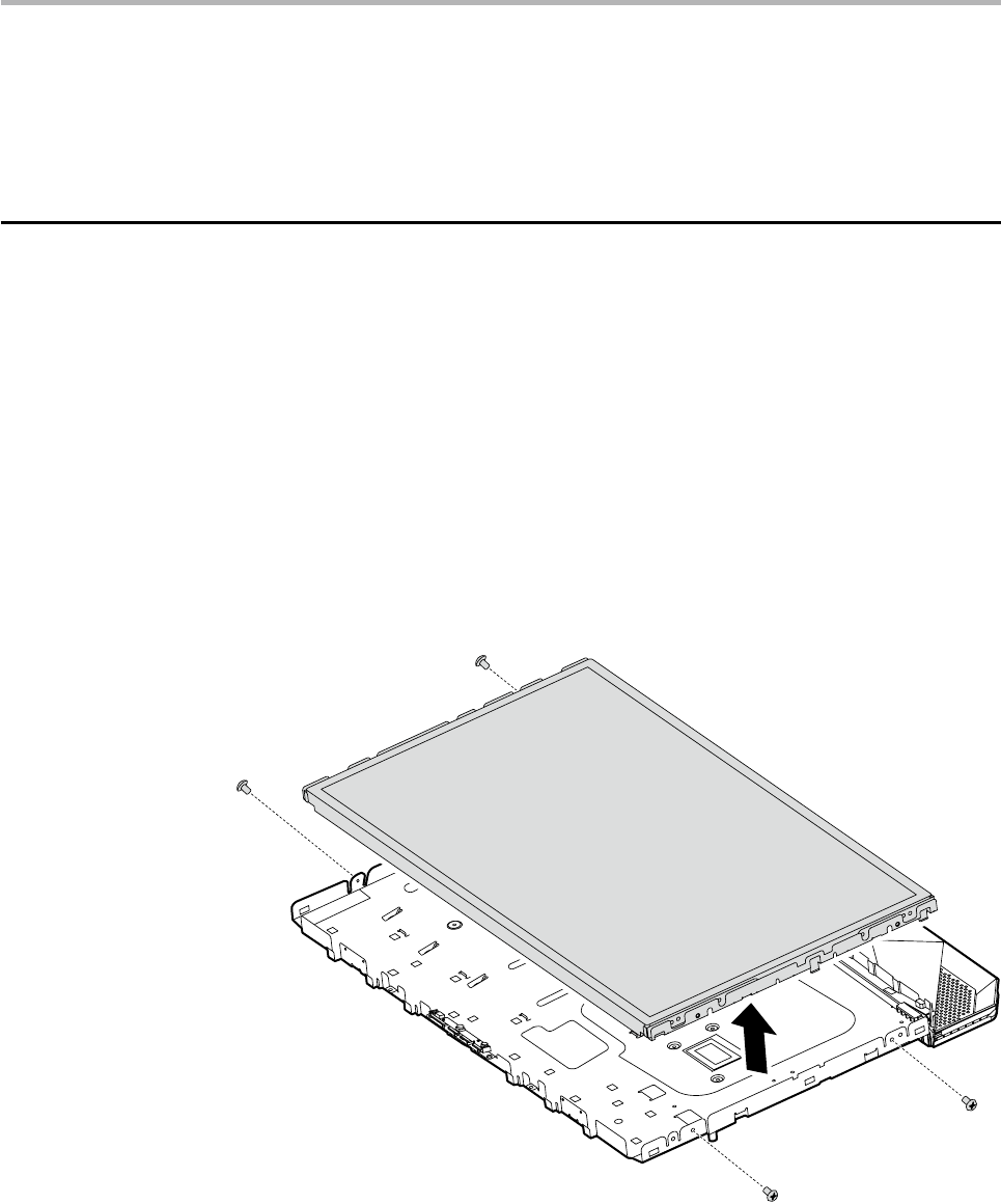
Replacing the LCD panel
To replace the LCD panel
1. Remove the computer cover. Refer to “Removing the computer cover”.
2. Remove the LCD back bezel. Refer to “Replacing the touch sensor
board”.
3. Disconnect the FPC cable from the LCD panel and the LVDs cable from
the system board.
4. Remove the LCD front bezel. Refer to “Replacing the touch sensor
board”.
5. Remove the four screws on the left and right side of the LCD panel.
6. Carefully detach the LCD panel from the chassis.
7. Place the new LCD panel to the chassis.

Hardware Maintenance Manual
52
Attention
Use an anti-electrostatic cloth to clean the LCD panel before installing
it to the chassis. You may dip a little alcohol if the LCD panel is dirty.
8. Screw back the four screws on the left and right side of the LCD panel.
9. Install the LCD bezel and computer.
Replacing the camera
To replace the camera
1. Remove the computer cover. Refer to “Removing the computer cover”.
2. Remove the LCD panel. Refer to “Replacing the LCD panel”.
3. Disconnect the camera cable from the camera.
4. Detach the camera from the chassis.
5. Connect the camera cable to the new camera.
6. Align then insert the camera into the chassis.
7. Install the computer.
Chapter 8. Replacing hardware
53
Replacing the keyboard
Attention
Do not remove the computer cover or attempt any repair before
reading the “Important safety information” in the Safety and Warranty
Guide that was included with your computer or in the Hardware
Maintenance Manual (HMM) for the computer. To obtain copies of the
Safety and Warranty Guide or HMM, go to the Support Web site at
http://consumersupport.lenovo.com.
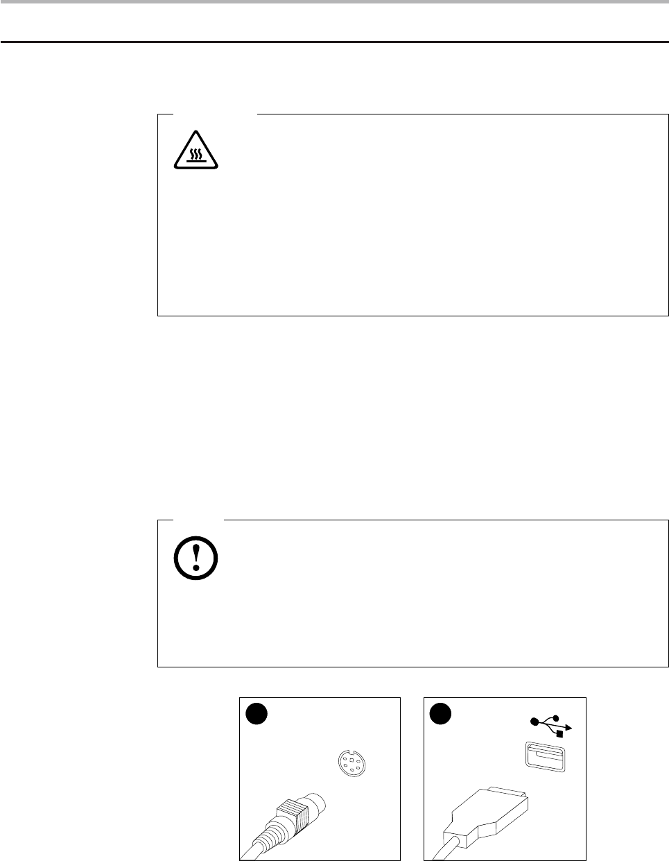
To replace the keyboard:
1. Remove any media (diskettes, CDs, or memory cards) from the drives,
shut down your operating system, and turn off all attached devices
and the computer.
2. Unplug all power cords from electrical outlets.
3. Locate the connector for the keyboard. Refer to “Left and right view”
and “Rear view” .
Note
Your keyboard might be connected to the standard keyboard
connector 1 at the rear of the computer or to a USB connector 2
either side or rear of the computer.
1 2
4. Disconnect the failing keyboard cable from the computer and connect
the new keyboard cable to the same connector.
Hardware Maintenance Manual
54
Replacing the Mouse
Attention
Do not remove the computer cover or attempt any repair before
reading the “Important safety information” in the Safety and Warranty
Guide that was included with your computer or in the Hardware
Maintenance Manual (HMM) for the computer. To obtain copies of the
Safety and Warranty Guide or HMM, go to the Support Web site at
http://consumersupport.lenovo.com.
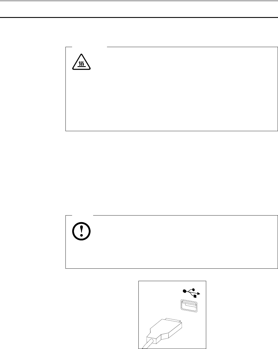
To replace the Mouse:
1. Remove any media (diskettes, CDs, or memory cards) from the drives,
shut down your operating system, and turn off all attached devices
and the computer.
2. Unplug all power cords from electrical outlets.
3. Locate the connector for the mouse. Refer to “Left and right view” and
“Rear view” .
Note
Your mouse connected to the USB connector at either side or the rear
of the computer.
4. Disconnect the failing keyboard cable from the computer and connect
the new mouse cable to the same connector.
Chapter 8. Replacing hardware
55
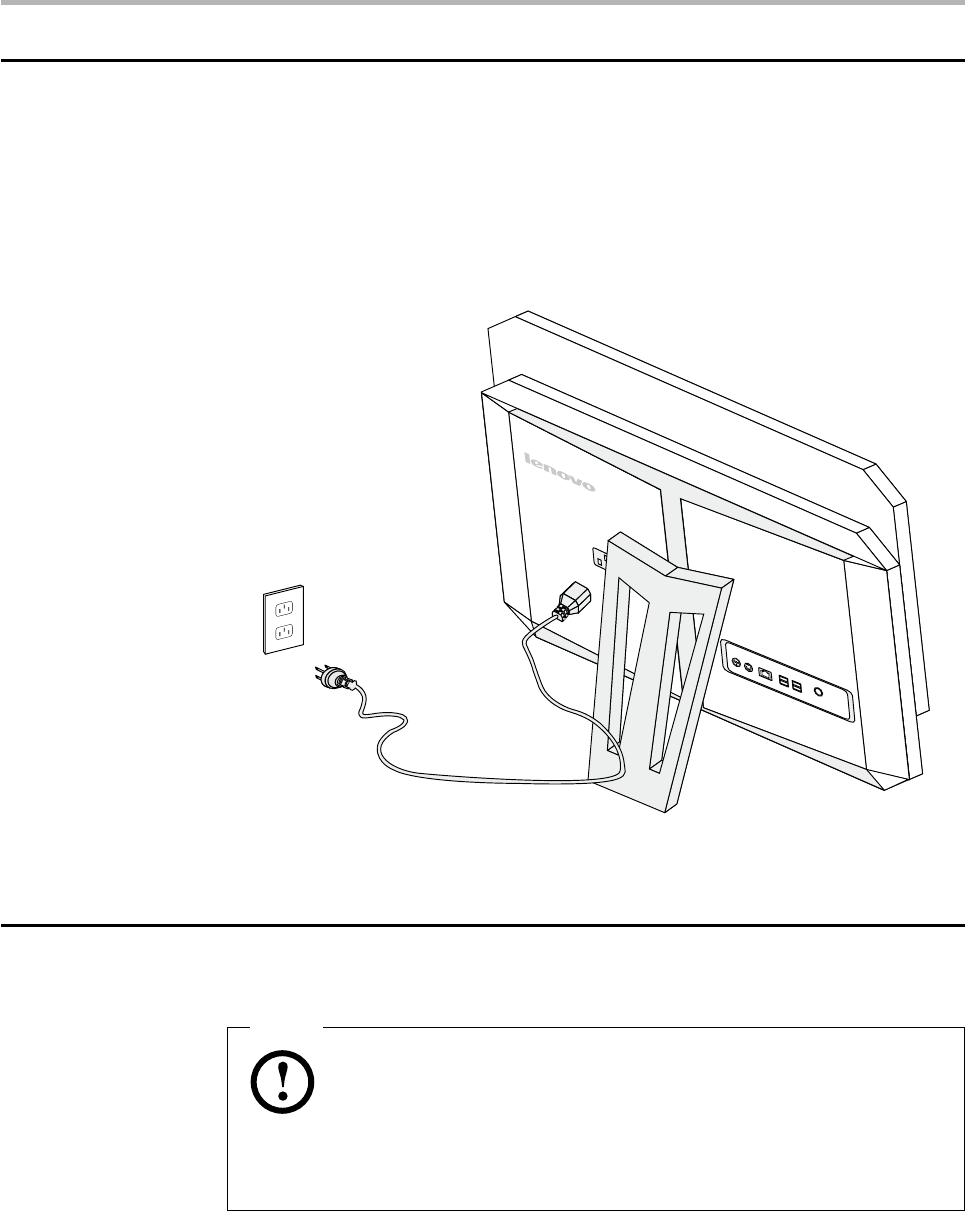
Replacing the power cord or power adapter
To replace the power cord and power adapter:
1. Remove any media (diskettes, CDs, or memory cards) from the drives,
shut down your operating system, and turn off all attached devices
and the computer.
2. Locate the connector for the power cord. Refer to “Rear view”.
3. Disconnect the failing power cord from the computer and connect the
new power cord to the same connector.
Replacing the remote control
Note
Remove the batteries from the failing remote control before you
return it to Lenovo for a replacement.

Hardware Maintenance Manual
56
Additional Service
Information 9
This chapter provides additional information that the service
representative might find helpful.
Power management
Power management reduces the power consumption of certain
components of the computer such as the system power supply, processor,
hard disk drives, and some monitors.
Automatic configuration and power interface (ACPI)
BIOS
Being an ACPI BIOS system, the operating system is allowed to control
the power management features of the computer and the setting for
Advanced Power Management (APM) BIOS mode is ignored. Not all
operating systems support ACPI BIOS mode.
Automatic Power-On features
The Automatic Power-On features within the Power Management menu
allow you to enable and disable features that turn on the computer
automatically.
Resume On RTC Alarm: You can specify a date and time at which the •
computer will be turned on automatically. This can be either a single
event or a daily event.
On LAN Wake Up: This feature allows LAN adapter card to wake the •
System.

Appendix. Statement
57
Statement A
Thank you for using Lenovo products.
Carefully read all of the documents shipped with your computer before
you install and use the product for the first time. Lenovo will not assume
responsibility for damage that results from failure to operate the product
according to the instructions and requirements described in the manuals
included with your computer. Lenovo will not assume responsibility for
any loss incurred except those resulting from installation or operations
carried out by Lenovo professional service staff.
Lenovo has made every attempt to ensure that the manuals included with
your computer are correct and accurate, but makes no guarantee that the
publications are error free.
To provide better service, Lenovo reserves the right to improve and/or
modify the products and software programs described in the manuals
included with your computer and the content of the manual at any time
without notice.
All of the manuals included with your computer are provided to help you
use Lenovo products appropriately, but do not provide any description of
the software/hardware configuration for the product. For configuring the
product, refer to related contracts (if any), the product packing list for the
product or the retailer.
The content of the manuals included with your computer is protected
by copyright laws and rules. None of the manuals included with your
computer may be reproduced or transcribed by any means, or transmitted
through wired or wireless networks in any form, or translated into any
language without the prior written permission of Lenovo. All Lenovo
publications included with your system are protected by Copyright ©
2009 Lenovo.
The software and hardware configuration included with your computer
depends on the actual configuration of the computer and may differ from
other similar models.

Hardware Maintenance Manual
58
Customers are welcome to contact us regarding any inconsistency
between the product and the manuals included with your
computer. For the latest information or if you have any questions
or comments, please visit the consumer support website at:
http://consumersupport.lenovo.com.
Lenovo is a registered trademark of Lenovo.
Microsoft, Windows, and Windows Vista are trademarks of the Microsoft
group of companies.
Intel Inside is a registered trademark of Intel.
AMD, the AMD Arrow logo, ATI, the ATI logo, AMD Athlon, AMD LIVE, AMD
Opteron, AMD Phenom, AMD Sempron, Avivo, Catalyst, Cool ‘n’ Quiet,
CrossFireX, Overdrive, Powerplay, Radeon, The Ultimate Visual Experience,
and combinations thereof are trademarks of Advanced Micro Devices, Inc.
in the United States and/or other jurisdictions.
The table above includes the logo and registered trademarks of Lenovo
and its partners.
Other registered trademarks mentioned in any or all of the manuals
included with your computer belong to the specific company respectively.
The manual included with your computer is protected by copyright laws
and rules. None of the manuals included with your computer may be
reproduced or transcribed by any means, or transmitted through wired or
wireless networks in any form, or translated into any language without the
prior written permission of Lenovo.
The names or marks of companies mentioned in the manuals included
with your computer or this document are only used to assert trademark
rights, and they do not necessarily indicate that related software or
hardware is included. The actual configuration of the product depends on
the description of the specific model.
