Lenovo Thinkpad T41 T41P Users Manual T40/T40p, T41/T41p, T42/T42p
THINKPAD T40 IBM_Thinkpad_T40_T40p_T41_T41p_T42_T42p
T41T41P to the manual ec189471-8143-4d44-868a-8a4aff9a4c76
thinkpad t40 t40p t41 t41p t42 t42p
2015-01-24
: Lenovo Lenovo-Thinkpad-T41-T41P-Users-Manual-328643 lenovo-thinkpad-t41-t41p-users-manual-328643 lenovo pdf
Open the PDF directly: View PDF ![]() .
.
Page Count: 260 [warning: Documents this large are best viewed by clicking the View PDF Link!]
- Contents
- About this manual
- Introduction
- General descriptions
- ThinkPad T40/T40p, T41/T41p, T42/T42p Series
- Product overview
- Symptom-to-FRU index
- FRU replacement notices
- Removing and replacing a FRU
- 1010 Battery pack for 14.1-in. LCD models
- 1020 Battery pack for 15.0-in. LCD models
- 1030 Ultrabay Slim device
- 1040 Hard disk drive
- 1050 DIMM (optional)
- 1060 Keyboard
- 1070 DIMM (standard)
- 1080 Modem daughter card (MDC/MDC-2)
- 1090 Bluetooth/Modem daughter card (BMDC/BMDC-2)
- 1100 Palm rest or Palm rest with fingerprint sensor (for 14.1-in. LCD models)
- 1110 Keyboard bezel or Keyboard bezel with fingerprint sensor (for 15.0-in. LCD models)
- 1120 Mini PCI adapter
- 1130 Fan assembly
- 1140 Backup battery for 14.1-in. LCD models
- 1150 Backup battery for 15.0-in. LCD models
- 1160 Speaker assembly
- 1170 Keyboard bezel for 14.1-in. LCD models
- 1180 PC Card slot assembly for 14.1-in. LCD models
- 1190 PC Card slot assembly for 15.0-in. LCD models
- 1200 LCD assembly for 14.1-in. LCD models
- 1210 LCD assembly for 15.0-in. LCD models
- 1220 CPU
- 1230 Ultrabay Slim guide rail assembly for 14.1-in. LCD models
- 1240 Ultrabay Slim guide rail assembly for 15.0-in. LCD models
- 1250 VGA and Ultrabay Slim device eject button cable
- 1260 System board and base cover for 14.1-in. LCD models
- 1270 System board, interposer card, and base cover for 15.0-in. LCD models
- 2010 LCD front bezel for 14.1-in. LCD models
- 2020 LCD front bezel for 15.0-in. LCD models
- 2030 Inverter card for 14.1-in. LCD models
- 2040 Inverter card for 15.0-in. LCD models
- 2050 Wireless antenna assemblies, LCD panel, LCD cable assembly, hinges, and LCD cover for 14.1-in. LCD models
- 2060 Wireless antenna assemblies, LCD panel, LCD cable assembly, hinges, and LCD cover for 15.0-in. LCD models
- 3010 ThinkPad Dock II PCI cover
- 3020 ThinkPad Dock II top cover
- Locations
- Parts list
- Notices
- Trademarks
ThinkPad Computer
Hardware Maintenance Manual
February 2006
This manual supports:
ThinkPad T40/T40p, T41/T41p, T42/T42p
ThinkPad Dock II (MT 2877)
(MT 2373/2374/ / )
2375 2376/2378/2379

Note
Before using this information and the product it
supports, be sure to read the general information
under “Notices” on page 250.
Second Edition (February 2006)
© Copyright Lenovo 2006.
Portions © Copyright International Business Machines
Corporation 2006.
All rights reserved.
U.S. GOVERNMENT USERS – RESTRICTED RIGHTS:
Our products and/or services are provided with
RESTRICTED RIGHTS. Use, duplication or disclosure by
the Government is subject to the GSA ADP Schedule
contract with Lenovo Group Limited, if any, or the standard
terms of this commercial license, or if the agency is unable
to accept this Program under these terms, then we provide
this Program under the provisions set forth in Commercial
Computer Software–Restricted Rights at FAR 52.227-19,
when applicable, or under Rights in Data-General, FAR
52.227.14 (Alternate III).

Contents
About this manual . . . . . . . . . . .1
Introduction . . . . . . . . . . . . .3
Important service information . . . . . . . . .3
Strategy for replacing FRUs . . . . . . . .3
How to use error messages . . . . . . . .4
Diskette compatibility matrix . . . . . . . . .4
Safety notices: multilingual translations . . . . . .4
Safety information . . . . . . . . . . . .16
General safety . . . . . . . . . . . .16
Electrical safety . . . . . . . . . . .17
Safety inspection guide . . . . . . . . .19
Handling devices that are sensitive to electrostatic
discharge . . . . . . . . . . . .20
Grounding requirements . . . . . . . . .21
Laser compliance statement . . . . . . . . .22
General descriptions . . . . . . . . . .25
Read this first . . . . . . . . . . . . .25
What to do first . . . . . . . . . . .25
Related service information . . . . . . . . .27
Service Web site . . . . . . . . . . .27
Restoring the pre-installed system . . . . . .27
Passwords . . . . . . . . . . . . .28
Power management . . . . . . . . . .32
Checkout guide . . . . . . . . . . . .35
Testing the computer . . . . . . . . . .35
Detecting system information with PC-Doctor . . .38
Power system checkout . . . . . . . . .39
ThinkPad T40/T40p, T41/T41p, T42/T42p Series 43
Product overview . . . . . . . . . . . .45
Specifications . . . . . . . . . . . .45
Status indicators . . . . . . . . . . .50
FRU tests . . . . . . . . . . . . .53
Fn key combinations . . . . . . . . . .54
Symptom-to-FRU index . . . . . . . . . .58
Numeric error codes . . . . . . . . . .58
Error messages . . . . . . . . . . .62
Beep symptoms . . . . . . . . . . .63
No-beep symptoms . . . . . . . . . .63
LCD-related symptoms . . . . . . . . .64
Intermittent problems . . . . . . . . . .65
Undetermined problems . . . . . . . . .65
FRU replacement notices . . . . . . . . .66
Screw notices . . . . . . . . . . . .66
Retaining serial numbers . . . . . . . . .67
Removing and replacing a FRU . . . . . . . .70
1010 Battery pack for 14.1-in. LCD models . . .71
1020 Battery pack for 15.0-in. LCD models . . .73
© Lenovo 2006. Portions © IBM Corp. 2006. iii
1030 Ultrabay Slim device . . . . . . . .74
1040 Hard disk drive . . . . . . . . . .75
1050 DIMM (optional) . . . . . . . . .77
1060 Keyboard . . . . . . . . . . .79
1070 DIMM (standard) . . . . . . . . .83
1080 Modem daughter card (MDC/MDC-2) . . .84
1090 Bluetooth/Modem daughter card
(BMDC/BMDC-2) . . . . . . . . . .86
1100 Palm rest or Palm rest with fingerprint sensor
(for 14.1-in. LCD models) . . . . . . . .88
1110 Keyboard bezel or Keyboard bezel with
fingerprint sensor (for 15.0-in. LCD models) . .91
1120 Mini PCI adapter . . . . . . . . .97
1130 Fan assembly . . . . . . . . . . 101
1140 Backup battery for 14.1-in. LCD models 106
1150 Backup battery for 15.0-in. LCD models 108
1160 Speaker assembly . . . . . . . .110
1170 Keyboard bezel for 14.1-in. LCD models 112
1180 PC Card slot assembly for 14.1-in. LCD
models . . . . . . . . . . . . .114
1190 PC Card slot assembly for 15.0-in. LCD
models . . . . . . . . . . . . .116
1200 LCD assembly for 14.1-in. LCD models 118
1210 LCD assembly for 15.0-in. LCD models 123
1220 CPU . . . . . . . . . . . . 128
1230 Ultrabay Slim guide rail assembly for 14.1-in.
LCD models . . . . . . . . . . . 129
1240 Ultrabay Slim guide rail assembly for 15.0-in.
LCD models . . . . . . . . . . . 131
1250 VGA and Ultrabay Slim device eject button
cable . . . . . . . . . . . . . 134
1260 System board and base cover for 14.1-in.
LCD models . . . . . . . . . . . 136
1270 System board, interposer card, and base
cover for 15.0-in. LCD models . . . . . . 145
2010 LCD front bezel for 14.1-in. LCD models 153
2020 LCD front bezel for 15.0-in. LCD models 155
2030 Inverter card for 14.1-in. LCD models . . . 157
2040 Inverter card for 15.0-in. LCD models . . . 159
2050 Wireless antenna assemblies, LCD panel,
LCD cable assembly, hinges, and LCD cover for
14.1-in. LCD models . . . . . . . . . 160
2060 Wireless antenna assemblies, LCD panel,
LCD cable assembly, hinges, and LCD cover for
15.0-in. LCD models . . . . . . . . . 175
3010 ThinkPad Dock II PCI cover . . . . . . 182
3020 ThinkPad Dock II top cover . . . . . . 183
Locations . . . . . . . . . . . . . . 186
Front view . . . . . . . . . . . . 186
Rear view . . . . . . . . . . . . . 188
Bottom view . . . . . . . . . . . . 189
Parts list . . . . . . . . . . . . . . 190
Overall . . . . . . . . . . . . . 191
iv T40/T40p, T41/T41p, T42/T42p
14.1-in. LCD FRUs . . . . . . . . . . 220
15.0-in. LCD FRUs . . . . . . . . . . 230
Keyboard . . . . . . . . . . . . . 235
Recovery CDs . . . . . . . . . . . 237
Miscellaneous parts . . . . . . . . . . 243
AC adapters . . . . . . . . . . . . 246
Optional FRUs . . . . . . . . . . . 247
Common parts list . . . . . . . . . . 248
Notices . . . . . . . . . . . . . . 250
Trademarks . . . . . . . . . . . . . 252
Contents v
vi T40/T40p, T41/T41p, T42/T42p

About this manual
This manual contains service and reference information for
ThinkPad
®
T40/T40p, T41/T41p, T42/T42p series
(MT2373, 2374, 2375, 2376, 2378, 2379, 2668, 2669,
2678, 2679, 2686, and 2687), and ThinkPad Dock II
(MT2877) products. Use this manual along with the
advanced diagnostic tests to troubleshoot problems.
The manual is divided into sections as follows:
v The common sections provide general information,
guidelines, and safety information required in servicing
computers.
v The product-specific section includes service, reference,
and product-specific parts information.
Important
This manual is intended for trained service
personnel who are familiar with ThinkPad products.
Use this manual along with the advanced diagnostic
tests to troubleshoot problems effectively.
Before servicing a ThinkPad product, be sure to
review the safety information under “Safety notices:
multilingual translations” on page 4, “Safety
information” on page 16, and “Laser compliance
statement” on page 22.
© Lenovo 2006. Portions © IBM Corp. 2006. 1
2 T40/T40p, T41/T41p, T42/T42p

Introduction
Important service information
Important
BIOS and device driver fixes are
customer-installable. The BIOS and device drivers
are posted on the customer support site
http://www.lenovo.com/support
Advise customers to contact the Customer Support
Center at 800-426-7378 if they need assistance in
obtaining or installing any diskette fixes.
Customers in Canada should call the Customer
Support Center at 800-565-3344 for assistance or
download information.
Strategy for replacing FRUs
Before replacing parts
Make sure that all diskette fixes are installed before
replacing any FRUs listed in this manual.
Use the following strategy to prevent unnecessary expense
for replacing and servicing FRUs:
v If you are instructed to replace a FRU but the
replacement does not correct the problem, reinstall
the original FRU before you continue.
v Some computers have both a processor board and a
system board. If you are instructed to replace either the
processor board or the system board, and replacing one
of them does not correct the problem, reinstall that
board, and then replace the other one.
v If an adapter or a device consists of more than one
FRU, any of the FRUs may be the cause of the error.
Before replacing the adapter or device, remove the
FRUs, one by one, to see if the symptoms change.
Replace only the FRU that changed the symptoms.
Attention: The setup configuration on the computer you
are servicing may have been customized. Running
Automatic Configuration may alter the settings. Note the
current configuration settings (using the View Configuration
option); then, when service has been completed, verify that
those settings remain in effect.
© Lenovo 2006. Portions © IBM Corp. 2006. 3

Strategy for replacing a hard disk drive
Always try to run a low-level format before replacing a hard
disk drive.
Attention: The drive startup sequence in the computer
you are servicing may have been changed. Be extremely
careful during write operations such as copying, saving, or
formatting. If you select an incorrect drive, data or
programs can be overwritten.
How to use error messages
Use the error codes displayed on the screen to diagnose
failures. If more than one error code is displayed, begin the
diagnosis with the first error code. Whatever causes the
first error code may also cause false error codes. If no
error code is displayed, see whether the error symptom is
listed in the Symptom-to-FRU Index for the computer you
are servicing.
Diskette compatibility matrix
The compatibility of each of the drives with the diskettes
for it is as follows:
Diskette
drive
Diskette
capacity
Compatibility
3.5-inch 1.0 MB Read and write
2.0 MB Read and write
4.0 MB Not compatible
Safety notices: multilingual translations
In this manual, safety notices appear in English with a
page number reference to the appropriate multilingual,
translated safety notice found in this section.
The following safety notices are provided in English,
French, German, Hebrew, Italian, and Spanish.
Important service information
4 T40/T40p, T41/T41p, T42/T42p

Safety notice 1
Before the computer is powered on after FRU
replacement, make sure all screws, springs, and other
small parts are in place and are not left loose inside
the computer. Verify this by shaking the computer and
listening for rattling sounds. Metallic parts or metal
flakes can cause electrical shorts.
Avant de remettre l’ordinateur sous tension après
remplacement d’une unité en clientèle, vérifiez que
tous les ressorts, vis et autres pièces sont bien en
place et bien fixées. Pour ce faire, secouez l’unité et
assurez-vous qu’aucun bruit suspect ne se produit. Des
pièces métalliques ou des copeaux de métal pourraient
causer un court-circuit.
Bevor nach einem FRU-Austausch der Computer
wieder angeschlossen wird, muß sichergestellt werden,
daß keine Schrauben, Federn oder andere Kleinteile
fehlen oder im Gehäuse vergessen wurden. Der
Computer muß geschüttelt und auf Klappergeräusche
geprüft werden. Metallteile oder-splitter können
Kurzschlüsse erzeugen.
Prima di accendere l’elaboratore dopo che é stata
effettuata la sostituzione di una FRU, accertarsi che
tutte le viti, le molle e tutte le altri parti di piccole
dimensioni siano nella corretta posizione e non siano
sparse all’interno dell’elaboratore. Verificare ciò
scuotendo l’elaboratore e prestando attenzione ad
eventuali rumori; eventuali parti o pezzetti metallici
possono provocare cortocircuiti pericolosi.
Antes de encender el sistema despues de sustituir una
FRU, compruebe que todos los tornillos, muelles y
demás piezas pequeñas se encuentran en su sitio y no
se encuentran sueltas dentro del sistema.
Compruébelo agitando el sistema y escuchando los
posibles ruidos que provocarían. Las piezas metálicas
pueden causar cortocircuitos eléctricos.
Safety notices
Introduction 5

Safety notice 2
DANGER
Some standby batteries contain a small amount of
nickel and cadmium. Do not disassemble a standby
battery, recharge it, throw it into fire or water, or
short-circuit it. Dispose of the battery as required
by local ordinances or regulations. Use only the
battery in the appropriate parts listing. Use of an
incorrect battery can result in ignition or explosion
of the battery.
Certaines batteries de secours contiennent du
nickel et du cadmium. Ne les démontez pas, ne les
rechargez pas, ne les exposez ni au feu ni à l’eau.
Ne les mettez pas en court-circuit. Pour les mettre
au rebut, conformez-vous à la réglementation en
vigueur. Lorsque vous remplacez la pile de
sauvegarde ou celle de l’horloge temps réel, veillez
à n’utiliser que les modèles cités dans la liste de
pièces détachées adéquate. Une batterie ou une
pile inappropriée risque de prendre feu ou
d’exploser.
Die Bereitschaftsbatterie, die sich unter dem
Diskettenlaufwerk befindet, kann geringe Mengen
Nickel und Cadmium enthalten. Sie darf nur durch
die Verkaufsstelle oder den IBM Kundendienst
ausgetauscht werden. Sie darf nicht zerlegt,
wiederaufgeladen, kurzgeschlossen, oder Feuer
oder Wasser ausgesetzt werden. Die Batterie kann
schwere Verbrennungen oder Verätzungen
verursachen. Bei der Entsorgung die örtlichen
Bestimmungen für Sondermüll beachten. Beim
Ersetzen der Bereitschafts-oder Systembatterie nur
Batterien des Typs verwenden, der in der
Ersatzteilliste aufgeführt ist. Der Einsatz falscher
Batterien kann zu Entzündung oder Explosion
führen.
(continued)
Safety notices
6 T40/T40p, T41/T41p, T42/T42p

(continuation of safety notice 2)
Alcune batterie di riserva contengono una piccola
quantità di nichel e cadmio. Non smontarle,
ricaricarle, gettarle nel fuoco o nell’acqua né
cortocircuitarle. Smaltirle secondo la normativa in
vigore (DPR 915/82, successive disposizioni e
disposizioni locali). Quando si sostituisce la
batteria dell’RTC (real time clock) o la batteria di
supporto, utilizzare soltanto i tipi inseriti
nell’appropriato Catalogo parti. L’impiego di una
batteria non adatta potrebbe determinare l’incendio
o l’esplosione della batteria stessa.
Algunas baterías de reserva contienen una
pequeña cantidad de níquel y cadmio. No las
desmonte, ni recargue, ni las eche al fuego o al
agua ni las cortocircuite. Deséchelas tal como
dispone la normativa local. Utilice sólo baterías que
se encuentren en la lista de piezas. La utilización
de una batería no apropiada puede provocar la
ignición o explosión de la misma.
Safety notices
Introduction 7

Safety notice 3
DANGER
The battery pack contains small amounts of nickel.
Do not disassemble it, throw it into fire or water, or
short-circuit it. Dispose of the battery pack as
required by local ordinances or regulations. Use
only the battery in the appropriate parts listing
when replacing the battery pack. Use of an
incorrect battery can result in ignition or explosion
of the battery.
La batterie contient du nickel. Ne la démontez pas,
ne l’exposez ni au feu ni à l’eau. Ne la mettez pas
en court-circuit. Pour la mettre au rebut,
conformez-vous à la réglementation en vigueur.
Lorsque vous remplacez la batterie, veillez à
n’utiliser que les modèles cités dans la liste de
pièces détachées adéquate. En effet, une batterie
inappropriée risque de prendre feu ou d’exploser.
Akkus enthalten geringe Mengen von Nickel. Sie
dürfen nicht zerlegt, wiederaufgeladen,
kurzgeschlossen, oder Feuer oder Wasser
ausgesetzt werden. Bei der Entsorgung die
örtlichen Bestimmungen für Sondermüll beachten.
Beim Ersetzen der Batterie nur Batterien des Typs
verwenden, der in der Ersatzteilliste aufgeführt ist.
Der Einsatz falscher Batterien kann zu Entzündung
oder Explosion führen.
(continued)
Safety notices
8 T40/T40p, T41/T41p, T42/T42p

(continuation of safety notice 3)
La batteria contiene piccole quantità di nichel. Non
smontarla, gettarla nel fuoco o nell’acqua né
cortocircuitarla. Smaltirla secondo la normativa in
vigore (DPR 915/82, successive disposizioni e
disposizioni locali). Quando si sostituisce la
batteria, utilizzare soltanto i tipi inseriti
nell’appropriato Catalogo parti. L’impiego di una
batteria non adatta potrebbe determinare l’incendio
o l’esplosione della batteria stessa.
Las baterías contienen pequeñas cantidades de
níquel. No las desmonte, ni recargue, ni las eche al
fuego o al agua ni las cortocircuite. Deséchelas tal
como dispone la normativa local. Utilice sólo
baterías que se encuentren en la lista de piezas al
sustituir la batería. La utilización de una batería no
apropiada puede provocar la ignición o explosión
de la misma.
Safety notices
Introduction 9

Safety notice 4
DANGER
The lithium battery can cause a fire, an explosion,
or a severe burn. Do not recharge it, remove its
polarized connector, disassemble it, heat it above
100°C (212°F), incinerate it, or expose its cell
contents to water. Dispose of the battery as
required by local ordinances or regulations. Use
only the battery in the appropriate parts listing. Use
of an incorrect battery can result in ignition or
explosion of the battery.
La pile de sauvegarde contient du lithium. Elle
présente des risques d’incendie, d’explosion ou de
brûlures graves. Ne la rechargez pas, ne retirez pas
son connecteur polarisé et ne la démontez pas. Ne
l’exposez pas à une temperature supérieure à
100°C, ne la faites pas brûler et n’en exposez pas
le contenu à l’eau. Mettez la pile au rebut
conformément à la réglementation en vigueur. Une
pile inappropriée risque de prendre feu ou
d’exploser.
Die Systembatterie ist eine Lithiumbatterie. Sie
kann sich entzünden, explodieren oder schwere
Verbrennungen hervorrufen. Batterien dieses Typs
dürfen nicht aufgeladen, zerlegt, über 100 C erhitzt
oder verbrannt werden. Auch darf ihr Inhalt nicht
mit Wasser in Verbindung gebracht oder der zur
richtigen Polung angebrachte Verbindungsstecker
entfernt werden. Bei der Entsorgung die örtlichen
Bestimmungen für Sondermüll beachten. Beim
Ersetzen der Batterie nur Batterien des Typs
verwenden, der in der Ersatzteilliste aufgeführt ist.
Der Einsatz falscher Batterien kann zu Entzündung
oder Explosion führen.
(continued)
Safety notices
10 T40/T40p, T41/T41p, T42/T42p
(continuation of safety notice 4)
La batteria di supporto e una batteria al litio e puo
incendiarsi, esplodere o procurare gravi ustioni.
Evitare di ricaricarla, smontarne il connettore
polarizzato, smontarla, riscaldarla ad una
temperatura superiore ai 100 gradi centigradi,
incendiarla o gettarla in acqua. Smaltirla secondo
la normativa in vigore (DPR 915/82, successive
disposizioni e disposizioni locali). L’impiego di una
batteria non adatta potrebbe determinare l’incendio
o l’esplosione della batteria stessa.
La batería de repuesto es una batería de litio y
puede provocar incendios, explosiones o
quemaduras graves. No la recargue, ni quite el
conector polarizado, ni la desmonte, ni caliente por
encima de los 100°C (212°F), ni la incinere ni
exponga el contenido de sus celdas al agua.
Deséchela tal como dispone la normativa local.
Safety notices
Introduction 11

Safety notice 5
If the LCD breaks and the fluid from inside the LCD
gets into your eyes or on your hands, immediately
wash the affected areas with water for at least 15
minutes. Seek medical care if any symptoms from the
fluid are present after washing.
Si le panneau d’affichage à cristaux liquides se brise et
que vous recevez dans les yeux ou sur les mains une
partie du fluide, rincez-les abondamment pendant au
moins quinze minutes. Consultez un médecin si des
symptômes persistent après le lavage.
Die Leuchtstoffröhre im LCD-Bildschirm enthält
Quecksilber. Bei der Entsorgung die örtlichen
Bestimmungen für Sondermüll beachten. Der
LCD-Bildschirm besteht aus Glas und kann zerbrechen,
wenn er unsachgemäß behandelt wird oder der
Computer auf den Boden fällt. Wenn der Bildschirm
beschädigt ist und die darin befindliche Flüssigkeit in
Kontakt mit Haut und Augen gerät, sollten die
betroffenen Stellen mindestens 15 Minuten mit Wasser
abgespült und bei Beschwerden anschließend ein Arzt
aufgesucht werden.
Nel caso che caso l’LCD si dovesse rompere ed il
liquido in esso contenuto entrasse in contatto con gli
occhi o le mani, lavare immediatamente le parti
interessate con acqua corrente per almeno 15 minuti;
poi consultare un medico se i sintomi dovessero
permanere.
Si la LCD se rompe y el fluido de su interior entra en
contacto con sus ojos o sus manos, lave
inmediatamente las áreas afectadas con agua durante
15 minutos como mínimo. Obtenga atención medica si
se presenta algún síntoma del fluido despues de
lavarse.
Safety notices
12 T40/T40p, T41/T41p, T42/T42p
Safety notice 6
DANGER
To avoid shock, do not remove the plastic cover
that protects the lower part of the inverter card.
Afin d’éviter tout risque de choc électrique, ne
retirez pas le cache en plastique protégeant la
partie inférieure de la carte d’alimentation.
Aus Sicherheitsgründen die Kunststoffabdeckung,
die den unteren Teil der Spannungswandlerplatine
umgibt, nicht entfernen.
Per evitare scosse elettriche, non rimuovere la
copertura in plastica che avvolge la parte inferiore
della scheda invertitore.
Para evitar descargas, no quite la cubierta de
plástico que rodea la parte baja de la tarjeta
invertida.
Safety notices
Introduction 13
Safety notice 7
DANGER
Though the main batteries have low voltage, a
shorted or grounded battery can produce enough
current to burn personnel or combustible materials.
Bien que le voltage des batteries principales soit
peu élevé, le court-circuit ou la mise à la masse
d’une batterie peut produire suffisamment de
courant pour brûler des matériaux combustibles ou
causer des brûlures corporelles graves.
Obwohl Hauptbatterien eine niedrige Spannung
haben, können sie doch bei Kurzschluß oder
Erdung genug Strom abgeben, um brennbare
Materialien zu entzünden oder Verletzungen bei
Personen hervorzurufen.
Sebbene le batterie di alimentazione siano a basso
voltaggio, una batteria in corto circuito o a massa
può fornire corrente sufficiente da bruciare
materiali combustibili o provocare ustioni ai tecnici
di manutenzione.
Aunque las baterías principales tienen un voltaje
bajo, una batería cortocircuitada o con contacto a
tierra puede producir la corriente suficiente como
para quemar material combustible o provocar
quemaduras en el personal.
Safety notices
14 T40/T40p, T41/T41p, T42/T42p
Safety notice 8
DANGER
Before removing any FRU, power off the computer,
unplug all power cords from electrical outlets,
remove the battery pack, and then disconnect any
interconnecting cables.
Avant de retirer une unité remplaçable en clientèle,
mettez le système hors tension, débranchez tous
les cordons d’alimentation des socles de prise de
courant, retirez la batterie et déconnectez tous les
cordons d’interface.
Die Stromzufuhr muß abgeschaltet, alle Stromkabel
aus der Steckdose gezogen, der Akku entfernt und
alle Verbindungskabel abgenommen sein, bevor
eine FRU entfernt wird.
Prima di rimuovere qualsiasi FRU, spegnere il
sistema, scollegare dalle prese elettriche tutti i cavi
di alimentazione, rimuovere la batteria e poi
scollegare i cavi di interconnessione.
Antes de quitar una FRU, apague el sistema,
desenchufe todos los cables de las tomas de
corriente eléctrica, quite la batería y, a
continuación, desconecte cualquier cable de
conexión entre dispositivos.
Safety notices
Introduction 15

Safety information
The following section presents safety information with
which you need to be familiar before you service a
ThinkPad computer.
General safety
Follow these rules to ensure general safety:
v Observe good housekeeping in the area of the
machines during and after maintenance.
v When lifting any heavy object:
1. Make sure that you can stand safely without
slipping.
2. Distribute the weight of the object equally between
your feet.
3. Use a slow lifting force. Never move suddenly or
twist when you attempt to lift.
4. Lift by standing or by pushing up with your leg
muscles; this action removes the strain from the
muscles in your back. Do not attempt to lift any
object that weighs more than 16 kg (35 lb) or that
you think is too heavy for you.
v Do not perform any action that causes hazards to the
customer, or that makes the equipment unsafe.
v Before you start the machine, make sure that other
service representatives and the customer’s personnel
are not in a hazardous position.
v Place removed covers and other parts in a safe place,
away from all personnel, while you are servicing the
machine.
v Keep your toolcase away from walk areas so that other
people will not trip over it.
v Do not wear loose clothing that can be trapped in the
moving parts of a machine. Make sure that your sleeves
are fastened or rolled up above your elbows. If your hair
is long, fasten it.
v Insert the ends of your necktie or scarf inside clothing or
fasten it with a nonconductive clip, about 8 centimeters
(3 inches) from the end.
v Do not wear jewelry, chains, metal-frame eyeglasses, or
metal fasteners for your clothing.
Attention: Metal objects are good electrical
conductors.
v Wear safety glasses when you are hammering, drilling,
soldering, cutting wire, attaching springs, using solvents,
or working in any other conditions that might be
hazardous to your eyes.
Safety information
16 T40/T40p, T41/T41p, T42/T42p

v After service, reinstall all safety shields, guards, labels,
and ground wires. Replace any safety device that is
worn or defective.
v Reinstall all covers correctly before returning the
machine to the customer.
v Fan louvers on the machine help to prevent overheating
of internal components. Do not obstruct fan louvers or
cover them with labels or stickers.
WARNING
Handling the cord on this product or cords
associated with accessories sold with this product
will expose you to lead, a chemical known to the
State of California to cause cancer, and birth defects
or other reproductive harm. Wash hands after
handling.
Electrical safety
Observe the following rules when working on electrical
equipment.
Important
Use only approved tools and test equipment. Some
hand tools have handles covered with a soft
material that does not insulate you when working
with live electrical currents.
Many customers have, near their equipment, rubber
floor mats that contain small conductive fibers to
decrease electrostatic discharges. Do not use this
type of mat to protect yourself from electrical shock.
v Find the room emergency power-off (EPO) switch,
disconnecting switch, or electrical outlet. If an electrical
accident occurs, you can then operate the switch or
unplug the power cord quickly.
v Do not work alone under hazardous conditions or near
equipment that has hazardous voltages.
v Disconnect all power before:
– Performing a mechanical inspection
– Working near power supplies
– Removing or installing main units
v
Before you start to work on the machine, unplug the
power cord. If you cannot unplug it, ask the customer to
power-off the wall box that supplies power to the
machine, and to lock the wall box in the off position.
v If you need to work on a machine that has exposed
electrical circuits, observe the following precautions:
Safety information
Introduction 17
– Ensure that another person, familiar with the
power-off controls, is near you.
Attention: Another person must be there to switch
off the power, if necessary.
– Use only one hand when working with powered-on
electrical equipment; keep the other hand in your
pocket or behind your back.
Attention: An electrical shock can occur only when
there is a complete circuit. By observing the above
rule, you may prevent a current from passing through
your body.
– When using testers, set the controls correctly and
use the approved probe leads and accessories for
that tester.
– Stand on suitable rubber mats (obtained locally, if
necessary) to insulate you from grounds such as
metal floor strips and machine frames.
Observe the special safety precautions when you work
with very high voltages; Instructions for these
precautions are in the safety sections of maintenance
information. Use extreme care when measuring high
voltages.
v Regularly inspect and maintain your electrical hand tools
for safe operational condition.
v Do not use worn or broken tools and testers.
v Never assume that power has been disconnected from
a circuit. First, check that it has been powered off.
v Always look carefully for possible hazards in your work
area. Examples of these hazards are moist floors,
nongrounded power extension cables, power surges,
and missing safety grounds.
v Do not touch live electrical circuits with the reflective
surface of a plastic dental mirror. The surface is
conductive; such touching can cause personal injury and
machine damage.
v Do not service the following parts with the power on
when they are removed from their normal operating
places in a machine:
– Power supply units
– Pumps
– Blowers and fans
– Motor generators
and similar units. (This practice ensures correct
grounding of the units.)
v If an electrical accident occurs:
– Use caution; do not become a victim yourself.
– Switch off power.
– Send another person to get medical aid.
Safety information
18 T40/T40p, T41/T41p, T42/T42p
Safety inspection guide
The purpose of this inspection guide is to assist you in
identifying potentially unsafe conditions. As each machine
was designed and built, required safety items were
installed to protect users and service personnel from injury.
This guide addresses only those items. You should use
good judgment to identify potential safety hazards due to
attachment of non-ThinkPad features or options not
covered by this inspection guide.
If any unsafe conditions are present, you must determine
how serious the apparent hazard could be and whether
you can continue without first correcting the problem.
Consider these conditions and the safety hazards they
present:
v Electrical hazards, especially primary power (primary
voltage on the frame can cause serious or fatal
electrical shock)
v Explosive hazards, such as a damaged CRT face or a
bulging capacitor
v Mechanical hazards, such as loose or missing hardware
To determine whether there are any potentially unsafe
conditions, use the following checklist at the beginning of
every service task. Begin the checks with the power off,
and the power cord disconnected.
Checklist:
1. Check exterior covers for damage (loose, broken, or
sharp edges).
2. Power off the computer. Disconnect the power cord.
3. Check the power cord for:
a. A third-wire ground connector in good condition.
Use a meter to measure third-wire ground
continuity for 0.1 ohm or less between the external
ground pin and the frame ground.
b. The power cord should be the type specified in the
parts list.
c. Insulation must not be frayed or worn.
4. Remove the cover.
5. Check for any obvious non-ThinkPad alterations. Use
good judgment as to the safety of any non-ThinkPad
alterations.
6. Check inside the unit for any obvious unsafe
conditions, such as metal filings, contamination, water
or other liquids, or signs of fire or smoke damage.
7. Check for worn, frayed, or pinched cables.
Safety information
Introduction 19

8. Check that the power-supply cover fasteners (screws
or rivets) have not been removed or tampered with.
Handling devices that are sensitive to
electrostatic discharge
Any computer part containing transistors or integrated
circuits (ICs) should be considered sensitive to electrostatic
discharge (ESD.) ESD damage can occur when there is a
difference in charge between objects. Protect against ESD
damage by equalizing the charge so that the machine, the
part, the work mat, and the person handling the part are all
at the same charge.
Notes
1. Use product-specific ESD procedures when they
exceed the requirements noted here.
2. Make sure that the ESD protective devices you
use have been certified (ISO 9000) as fully
effective.
When handling ESD-sensitive parts:
v Keep the parts in protective packages until they are
inserted into the product.
v Avoid contact with other people.
v Wear a grounded wrist strap against your skin to
eliminate static on your body.
v Prevent the part from touching your clothing. Most
clothing is insulative and retains a charge even when
you are wearing a wrist strap.
v Use the black side of a grounded work mat to provide a
static-free work surface. The mat is especially useful
when handling ESD-sensitive devices.
v Select a grounding system, such as those listed below,
to provide protection that meets the specific service
requirement.
Note
The use of a grounding system to guard against
ESD damage is desirable but not necessary.
– Attach the ESD ground clip to any frame ground,
ground braid, or green-wire ground.
– When working on a double-insulated or
battery-operated system, use an ESD common
ground or reference point. You can use coax or
connector-outside shells on these systems.
Safety information
20 T40/T40p, T41/T41p, T42/T42p
– Use the round ground prong of the ac plug on
ac-operated computers.
Grounding requirements
Electrical grounding of the computer is required for
operator safety and correct system function. Proper
grounding of the electrical outlet can be verified by a
certified electrician.
Safety information
Introduction 21

Laser compliance statement
Some models of ThinkPad computer are equipped from
the factory with an optical storage device such as a
CD-ROM drive or a DVD-ROM drive. Such devices are
also sold separately as options. If one of these drives is
installed, it is certified in the U.S. to conform to the
requirements of the Department of Health and Human
Services 21 Code of Federal Regulations (DHHS 21 CFR)
Subchapter J for Class 1 laser products. Elsewhere, the
drive is certified to conform to the requirements of the
International Electrotechnical Commission (IEC) 825 and
CENELEC EN 60 825 for Class 1 laser products.
Laser compliance statement
22 T40/T40p, T41/T41p, T42/T42p
If a CD-ROM drive, a DVD-ROM drive, or another laser
device is installed, note the following:
CAUTION:
Opening the CD-ROM drive, the DVD-ROM drive, or any
other optical storage device could result in exposure to
hazardous laser radiation. There are no serviceable parts
inside those drives. Do not open.
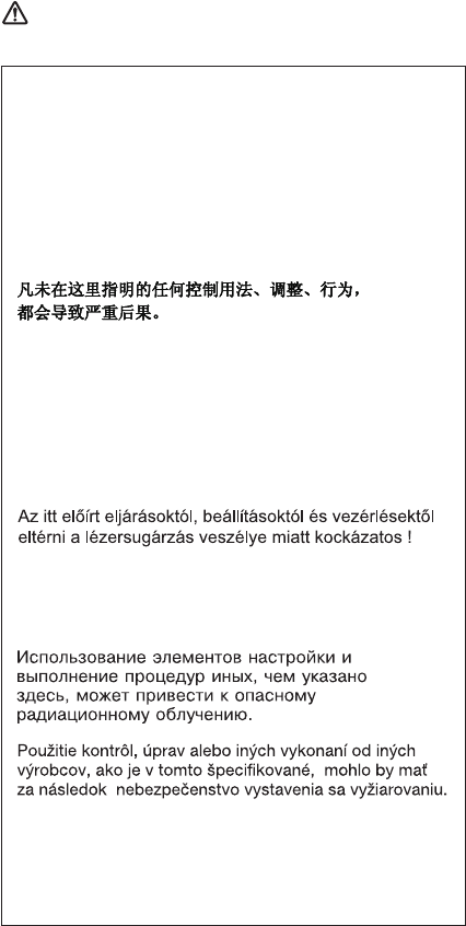
Use of controls or adjustments or performance of
procedures other than those specified herein might
result in hazardous radiation exposure.
O uso de controles, ajustes ou desempenho de
procedimentos diferentes daqueles aqui
especificados pode resultar em perigosa exposição
à radiação.
Pour éviter tout risque d’exposition au rayon laser,
respectez les consignes de réglage et d’utilisation
des commandes, ainsi que les procédures décrites.
Werden Steuer- und Einstellelemente anders als
hier festgesetzt verwendet, kann gefährliche
Laserstrahlung auftreten.
L’utilizzo di controlli, regolazioni o l’esecuzione di
procedure diverse da quelle specificate possono
provocare l’esposizione a.
El uso de controles o ajustes o la ejecución de
procedimientos distintos de los aquí especificados
puede provocar la exposición a radiaciones
peligrosas.
Laser compliance statement
Introduction 23
A CD-ROM drive, a DVD-ROM drive, or any other storage
device installed may contain an embedded Class 3A or
Class 3B laser diode. Note the following:
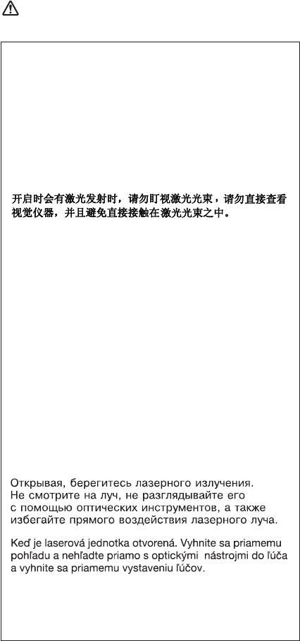
DANGER
Emits visible and invisible laser radiation when
open. Do not stare into the beam, do not view
directly with optical instruments, and avoid direct
exposure to the beam.
Radiação por raio laser ao abrir. Não olhe fixo no
feixe de luz, não olhe diretamente por meio de
instrumentos óticos e evite exposição direta com o
feixe de luz.
Rayonnement laser si carter ouvert. Évitez de fixer
le faisceau, de le regarder directement avec des
instruments optiques, ou de vous exposer au
rayon.
Laserstrahlung bei geöffnetem Gerät. Nicht direkt
oder über optische Instrumente in den Laserstrahl
sehen und den Strahlungsbereich meiden.
Kinyitáskor lézersugár ! Ne nézzen bele se szabad
szemmel, se optikai eszközökkel. Kerülje a
sugárnyalábbal való érintkezést !.
Aprendo l’unità vengono emesse radiazioni laser.
Non fissare il fascio, non guardarlo direttamente
con strumenti ottici e evitare l’esposizione diretta al
fascio.
Radiación láser al abrir. No mire fijamente ni
examine con instrumental óptico el haz de luz.
Evite la exposición directa al haz.
Laser compliance statement
24 T40/T40p, T41/T41p, T42/T42p

General descriptions
The desciptions in this chapter apply to any ThinkPad
model that has the PC-Doctor
®
DOS diagnostics program.
Some descriptions might not apply to your particular
computer.
Read this first
Before you go to the checkout guide, be sure to read this
section.
Important notes
v Only certified trained personnel should
service the computer.
v Before replacing any FRU, read the entire
page on removing and replacing FRUs.
v When you replace FRUs, use new
nylon-coated screws.
v Be extremely careful during such write
operations as copying, saving, or formatting.
Drives in the computer that you are servicing
sequence might have been altered. If you select
an incorrect drive, data or programs might be
overwritten.
v Replace an FRU only with another FRU of the
correct model. When you replace a FRU, make
sure that the model of the machine and the FRU
part number are correct by referring to the FRU
parts list.
v A FRU should not be replaced because of a
single, unreproducible failure. Single failures
can occur for a variety of reasons that have
nothing to do with a hardware defect, such as
cosmic radiation, electrostatic discharge, or
software errors. Consider replacing a FRU only
when a problem recurs. If you suspect that a
FRU is defective, clear the error log and run the
test again. If the error does not recur, do not
replace the FRU.
v Be careful not to replace a nondefective FRU.
What to do first
When you do return a FRU, you must include the following
information in the parts exchange form or parts return form
that you attach to it:
__ 1. Name and phone number of servicer
© Lenovo 2006. Portions © IBM Corp. 2006. 25
__ 2. Date of service
__ 3. Date on which the machine failed
__ 4. Date of purchase
__ 5. Failure symptoms, error codes appearing on the
display, and beep symptoms
__ 6. Procedure index and page number in which the
failing FRU was detected
__ 7. Failing FRU name and part number
__ 8. Machine type, model number, and serial number
__ 9. Customer’s name and address
Note for warranty:
During the warranty period, the customer may be
responsible for repair costs if the computer damage was
caused by misuse, accident, modification, unsuitable
physical or operating environment, or improper
maintenance by the customer. Following is a list of some
common items that are not covered under warranty and
some symptoms that might indicate that the system was
subjected to stress beyond normal use.
Before checking problems with the computer, determine
whether the damage is covered under the warranty by
referring to the following list:
The following are not covered under warranty:
v LCD panel cracked from the application of excessive
force or from being dropped
v Scratched (cosmetic) parts
v Distortion, deformation, or discoloration of the cosmetic
parts
v Plastic parts, latches, pins, or connectors that have
been cracked or broken by excessive force
v Damage caused by liquid spilled into the system
v Damage caused by the improper insertion of a PC Card
or the installation of an incompatible card
v Diskette drive damage caused by pressure on the
diskette drive cover, foreign material in the drive, or the
insertion of a diskette with multiple labels
v Damaged or bent diskette eject button
v Fuses blown by attachment of a nonsupported device
v Forgotten computer password (making the computer
unusable)
v Sticky keys caused by spilling a liquid onto the keyboard
The following symptoms might indicate damage
caused by nonwarranted activities:
v Missing parts might be a symptom of unauthorized
service or modification.
v If the spindle of a hard disk drive becomes noisy, it may
have been subjected to excessive force, or dropped.
Read this first
26 T40/T40p, T41/T41p, T42/T42p

Related service information
This section provides information about the following:
v “Service Web site”
v “Restoring the pre-installed system”
v “Passwords” on page 28
v “Power management” on page 32
Service Web site
When the latest maintenance diskette and the system
program service diskette become available, they will be
posted on http://www.lenovo.com/think/spm
Restoring the pre-installed system
When the hard disk drive is replaced because of a failure,
no Product Recovery program is on the new hard disk. In
this case, you must use the recovery CD for the computer.
Order the recovery CD and the hard disk drive at the same
time so that you can recover the new hard disk drive with
the pre-installed software when they arrive. For information
on which CD to order, see “Recovery CDs” on page 237.
Recovery to Factory Contents by using
Product Recovery CDs
To create the service partition and install the factory
contents from the recovery CD, do the following:
Note
The recovery process might take up to 2 hours.
1. Insert the recovery CD into the CD or DVD drive, then
restart the computer.
2. Following message is displayed: “Your computer
originally included a Product Recovery program ...
Reinstall the Product Recovery program? (Y/N) [ ]”.
3. Press Y key. The service partition is created and
loaded with the Product Recovery program files.
4. At next window, press Enter to continue.
v The service partition is created. The system
automatically reboots during this process.
v The recovery process copies some files to the
service partition, and PKUNZIPs others.
v Follow the prompts. You may be prompted to
change CDs.
v When the process is complete, the system reboots.
Related service information
General descriptions 27
5. If you get a message asking which operating system to
install, select the proper operating system and press
Enter.
6. A message is displayed: “Full Recovery:”. Press Enter
to select.
7. On each of the next three windows, press the Y key.
8. Follow the prompts to complete the recovery.
Passwords
As many as three passwords may be needed for any
ThinkPad computer: the power-on password (POP), the
hard-disk password (HDP), and the supervisor password
(SVP).
If any of these passwords has been set, a prompt for it
appears on the screen whenever the computer is turned
on. The computer does not start until the password is
entered.
Exception: If only an SVP is installed, the password
prompt does not appear when the operating
system is booted.
Power-on password:
A power-on password (POP) protects the system from
being powered on by an unauthorized person. The
password must be entered before an operating system can
be booted.
Hard-disk password:
There are two hard-disk passwords (HDPs):
v User HDP—for the user
v Master HDP—for the system administrator, who can use
it to get access to the hard disk even if the user has
changed the user HDP
Note: There are two modes for the HDP: User only and
Master + User. The Master + User mode requires
two HDPs; the system administrator enters both in
the same operation. The system administrator then
provides the user HDP to the system user.
Attention: If the user HDP has been forgotten, check
whether a master HDP has been set. If it has, it can be
used for access to the hard disk drive. If no master HDP is
available, neither Lenovo nor Lenovo authorized servicers
provide any services to reset either the user or the master
HDP, or to recover data from the hard disk drive. The hard
disk drive can be replaced for a scheduled fee.
Supervisor password:
A supervisor password (SVP) protects the system
Related service information
28 T40/T40p, T41/T41p, T42/T42p
information stored in the BIOS Setup Utility. The user must
enter the SVP in order to get access to the BIOS Setup
Utility and change the system configuration.
Attention: If the SVP has been forgotten and cannot be
made available to the servicer, there is no service
procedure to reset the password. The system board must
be replaced for a scheduled fee.
How to remove the power-on password
To remove a POP that you have forgotten, do the
following:
(A) If no SVP has been set:
1. Turn off the computer.
2. Remove the battery pack.
For how to remove the battery pack, see “1010 Battery
pack for 14.1-in. LCD models” on page 71.
3. Remove the backup battery.
For how to remove the backup battery, see “1140
Backup battery for 14.1-in. LCD models” on page 106.
4. Turn on the computer and wait until the POST ends.
After the POST ends, the password prompt does not
appear. The POP has been removed.
5. Reinstall the backup battery and the battery pack.
(B) If an SVP has been set and is known by the servicer:
For T40/T40p, T41/T41p:
1. Turn on the computer and watch the lower left of the
screen for a message saying, “To interrupt normal
startup, press the blue Access IBM button.” When that
message appears, press the Access IBM button.
2. Enter the SVP. Double-click Start setup utility.
3. Select Security, using the cursor keys to move down
the menu.
4. Select Password.
5. Select Power-On Password.
6. At the Enter Current Password field, enter the SVP.
7. When the Enter New Password field opens, leave it
blank and press Enter twice.
8. In the Changes have been saved window, press Enter.
9. Press F10; then, in the Setup confirmation window,
select Yes.
For T42/T42p:
1. Turn on the computer; then, while the “To interrupt
normal startup, press the blue Access IBM button”
Related service information
General descriptions 29
message is displayed at the lower-left of the screen,
press the Access IBM button. The Rescue and
Recovery screen opens.
For models supporting the Passphrase function, press
F1 while POP icon is appearing on the screen; then
enter the POP. For the other models, enter the POP.
Note: To check whether the ThinkPad computer
supports the Passphrase function, enter BIOS
Setup Utility and go to Security --> Password.
If Using Passphrase item is displayed in the
menu, this function is available on the ThinkPad
computer.
2. Click Access BIOS. The system Restart Required
window is displayed.
3. Click Yes. The computer restarts, and the BIOS Setup
Utility screen opens.
4. Select Security, using the cursor directional keys to
move down the menu.
5. Select Password.
6. Select Power-On Password.
7. Type the current SVP in the Enter Current Password
field. then leave the Enter New Password field blank,
and press Enter twice.
8. In the Changes have been saved window, press Enter.
9. Press F10; then, in the Setup confirmation window,
select Yes .
How to remove the hard-disk password
Attention: If User only mode is selected and the user
HDP has been forgotten and cannot be made available to
the servicer, neither Lenovo nor Lenovo authorized
servicers provide any services to reset the user HDPs or to
recover data from the hard disk drive. The hard disk drive
can be replaced for a scheduled fee.
To remove a user HDP that has been forgotten, when the
SVP and the master HDP are known, do the following:
For T40/T40p, T41/T41p series:
1. Turn on the computer and watch the lower left of the
screen for a message saying, “To interrupt normal
startup, press the blue Access IBM button.” When that
message appears, press the Access IBM button.
2. For the ThinkPad T40 and T40p series, enter the
master HDP. For the ThinkPad T41 and T41 series,
press F1 while HDP icon is appearing on the screen;
then enter the master HDP.
3. Select Start setup utility. Enter the SVP.
Related service information
30 T40/T40p, T41/T41p, T42/T42p
4. Select Security, using the cursor keys to move down
the menu.
5. Select Password.
6. Select Hard-disk x password, where x is the letter of
the hard disk drive. A pop-up window opens.
7. Select Master HDP.
8. Enter the master HDP; then leave the New Password
field blank and press Enter twice.
9. Press F10.
10. Select Yes in the Setup Configuration window.
Both user HDP and master HDP will have been
removed.
For T42/T42p series:
1. Turn on the computer; then, while the “To interrupt
normal startup, press the blue Access IBM button”
message is displayed at the lower-left of the screen,
press the Access IBM button. The Rescue and
Recovery screen opens.
For models supporting the Passphrase function, press
F1 while HDP icon is appearing on the screen; then
enter the master HDP. For the other models, enter the
master HDP.
Note: To check whether the ThinkPad computer
supports the Passphrase function, enter BIOS
Setup Utility and go to Security --> Password.
If Using Passphrase item is displayed in the
menu, this function is available on the
ThinkPad computer.
2. Click Access BIOS. The system Restart Required
window is displayed.
3. Click Yes. The computer restarts, and the BIOS Setup
Utility screen opens.
4. Select Security, using the cursor directional keys to
move down the menu.
5. Select Password.
6. Select Hard-disk x password, where x is the letter of
the hard disk drive. A pop-up window opens.
7. Select Master HDP.
8. Type the current master HDP in the Enter Current
Password field. then leave the Enter New Password
field blank, and press Enter twice.
9. Press F10.
10. Select Yes in the Setup Configuration window.
Both user HDP and master HDP will have been
removed.
Related service information
General descriptions 31
Power management
To reduce power consumption, the computer has three
power management modes: screen blank, standby, and
hibernation.
Screen blank mode
Screen blank mode has three variants, as follows:
1. If you press Fn+F3, or if the time set on the “LCD off
timer” in BIOS Setup Utility expires,
v The LCD backlight turns off.
v The hard disk drive motor stops.
v The speaker is muted.
2. If you are using the ACPI operating system and you
press Fn+F3,
v The LCD backlight turns off.
v The hard disk drive motor stops.
3. If the time set on the “Turn off monitor” timer in the
operating system expires,
v The LCD backlight turns off.
To end screen blank mode and resume normal operation,
press any key.
Standby mode
When the computer enters standby mode, the following
events occur in addition to what occurs in screen blank
mode:
v The LCD is powered off.
v The hard disk drive is powered off.
v The CPU stops.
To enter standby mode, press Fn+F4.
Note: If you are using the ACPI operating system, you can
change the action of Fn+F4.s
In certain circumstances, the computer goes into standby
mode automatically:
v If a “suspend time” has been set on the timer, and the
user does not do any operation with the keyboard, the
TrackPoint, the hard disk, the parallel connector, or the
diskette drive within that time.
v If the battery indicator blinks orange, indicating that the
battery power is low. (Alternatively, if Hibernate when
battery becomes low has been selected in the “Power
Management Properties” window, the computer goes
into hibernation mode.)
Note for the APM operating system:
Even if you do not set the low-battery alarm, the charge
indicator notifies you when the battery is low, and then the
Related service information
32 T40/T40p, T41/T41p, T42/T42p

computer enters the power-saving mode automatically.
This default low-battery behavior is independent of the
operating system; so if you have set the low-battery alarm,
the computer may not do what you specified. It chooses
either your setting or the default setting, whichever is
appropriate.
If you are using the ACPI operating system, only the
low-battery alarm is available.
To cause the computer to return from standby mode and
resume operation, do one of the following:
v Press the Fn key.
v Open the LCD cover.
v Turn on the power switch.
Also, in either of the following events, the computer
automatically returns from standby mode and resumes
operation:
v
The ring indicator (RI) is signaled by a serial device or a
PC Card device.
v The time set on the resume timer elapses.
Note: The computer does not accept any input
immediately after it enters standby mode. Wait a
few seconds before taking any action to reenter
operation mode.
Hibernation mode
Note for OS/2
If you are using OS/2 in the default format, HPFS,
you cannot create a hibernation file. If you want to
use hibernation mode, you will need to reinstall
OS/2 with FAT format.
In hibernation mode, the following occurs:
v The system status, RAM, VRAM, and setup data are
stored on the hard disk.
v The system is powered off.
Note: If the computer enters the hibernation mode while it
is docked to the docking station, do not undock it
before resuming normal operation. If you do undock
it and then try to resume normal operation, you will
get an error message, and you will have to restart
the system.
To cause the computer to enter hibernation mode, do any
of the following:
v Press the Fn+F12 keys.
Related service information
General descriptions 33
v If you are using the APM operating system and have set
the mode to Power switch mode [Hibernation], turn
off the power switch.
v If you are using the ACPI operating system and have
defined one of the following actions as the event that
causes the system to go into hibernation mode, perform
that action.
– Closing the lid.
– Pressing the power button.
– Pressing Fn+F4 keys.
Also, the computer goes into hibernation mode
automatically in either of the following conditions:
v
If a “hibernation time” has been set on the timer, and if
the user does not do any operation with the keyboard,
the TrackPoint, the hard disk drive, the parallel
connector, or the diskette drive within that time.
v If the timer conditions are satisfied in suspend mode.
v If you are using the APM operating system and have set
the mode to Hibernate when battery becomes low,
and the battery charge becomes critically low.
When the power is turned on, the computer returns from
hibernation mode and resumes operation. The hibernation
file in the boot record on the hard disk drive is read, and
system status is restored from the hard disk drive.
Related service information
34 T40/T40p, T41/T41p, T42/T42p

Checkout guide
Use the following procedures as a guide in identifying and
correcting problems with the ThinkPad computer.
Note: The diagnostic tests are intended to test only
ThinkPad products. The use of non-ThinkPad
products, prototype cards, or modified options can
lead to false indications of errors and invalid system
responses.
1. Identify the failing symptoms in as much detail as
possible.
2. Verify the symptoms. Try to re-create the failure by
running the diagnostic test or by repeating the
operation.
Testing the computer
The ThinkPad computer has a test program called
PC-Doctor for DOS (hereafter called PC-Doctor.) You can
detect errors by running the diagnostics test included in
PC-Doctor. This section is an overview of the procedure.
For details that depend on model-unique functions, refer to
“Product overview” on page 45.
For some possible configurations of the computer,
PC-Doctor might not run correctly. To avoid this problem,
you need to initialize the computer setup by use of the
BIOS Setup Utility before you run PC-Doctor. On the BIOS
Setup Utility screen, press F9, Enter, F10, and then Enter.
Note: When you initialize the computer configuration,
some devices are disabled, such as the serial port.
If you test one of these devices, you will need to
enable it by using Configuration utility for DOS. The
utility is available on the following Web site:
http://www.lenovo.com/support
PC-Doctor cannot be used to test a device that is in the
docking station, even if the computer supports the docking
station. To test a USB device, connect it to the USB
connector of the computer.
Creating the PC-Doctor diagnostics diskette
To create the PC-Doctor disk from the Access IBM
Predesktop Area, do as follows:
1. Enter the Predesktop application by pressing the
Access IBM button during POST.
2. When the Access IBM application finishes loading,
double-click the “Create Diagnostic Diskettes” icon.
Checkout guide
General descriptions 35
3. Authenticating the digital signature takes about 15
seconds; then the ThinkPad computer will reboot into
PC-DOS.
4. A batch file automatically starts up to prompt you
through the process of creating diskettes. You are
notified of how many diskettes you will need.
a. You are prompted to insert each diskette in
sequence.
b. Typically, all you need to do is to press the Enter
key for the floppy drive; the system then formats
and creates the diskette.
c. Each diskette is erased and formatted with the
PC-Doctor for DOS boot image.
5. Once all the diskettes have been created, the
ThinkPad computer will reboot. The user is asked to
remove all diskettes from the drive, or to insert the first
diskette created if it is desired to run the diagnostics.
To run the test, do as follows:
Note: In the following procedure, you can select an item
not only with the arrow keys, but also with the
TrackPoint pointer. Instead of pressing Enter, click
the left button.
1. Insert the PC-Doctor disk into the diskette drive; then
power on the computer.
If the computer cannot be powered on, go to “Power
system checkout” on page 39, and check the power
sources.
If an error code appears, go to “Symptom-to-FRU
index” on page 58.
On the first screen, select the model and press Enter.
Follow the instructions on the screen.
2. The main panel of PC-Doctor appears.
3. Select Diagnostics with the arrow keys, and press
Enter.
A pull-down menu appears. (Its exact form depends on
the model.)
Note: PC-Doctor menu does not mean the formal
support device list. Some unsupported device
names may appear in the PC-Doctor menu.
Checkout guide
36 T40/T40p, T41/T41p, T42/T42p

The options on the test menu are as follows:
Diagnostics Interactive Tests
v Run Normal Test
v Run Quick Test
v CPU/Coprocessor
v Systemboard
v Video Adapter
v Serial Ports
v Parallel Ports
v Fixed Disks
v Diskette Drives
v Other Devices
v Communication
v Wireless LAN
v Memory Test – Full
v Memory Test – Quick
v Keyboard
v Video
v Internal Speaker
v Mouse
v Diskette
v System Load
v CD-ROM/DVD Test
v Intel Wireless Radio
Notes:
v In the Keyboard test in Interactive Tests, the Fn key
should be held down for at least 2 seconds; otherwise,
it cannot be sensed.
v Video Adapter test supports only the LCD display on
the ThinkPad computer. If you have an external
monitor attached to your computer, detach it before
running PC-Doctor for DOS.
v To test Digital Signature Chip, the chip must be
enabled.
v When Legacy Floppy Drives is enabled in the BIOS
Setup Utility, the Diskette Drives test is activated even
if no legacy diskette drive is attached to the ThinkPad
computer.
4. Run the applicable function test.
5. Follow the instructions on the screen. If there is a
problem, PC-Doctor shows messages describing it.
Diagnostics
Run Normal Test
Run Quick Test
CPU/Coprocessor
Systemboard
Video Adapter
Serial Ports
Parallel Ports
Fixed Disks
Diskette Drives
Other Devices
Communication
Memory Test - Full
Memory Test - Quick
Interactive Tests Hardware Info Utility Quit F1=Help
PC-DOCTOR 2.0 Copyright 2002 PC-Doctor, Inc. All Rights Reserved.
Use the cursor keys and ESC to move in menus. Press ENTER to select.
Wireless LAN
Checkout guide
General descriptions 37
6. To exit the test, select Quit — Exit Diag.
To cancel the test, press Esc.
Note: After running PC-Doctor, check the time and date
on the system and reset them if they are incorrect.
Detecting system information with
PC-Doctor
PC-Doctor can detect the following system information:
Hardware Info
v System Configuration
v Memory Contents
v Physical Disk Drives
v Logical Disk Drives
v VGA Information
v IDE Drive Info
v PCI Information
v PNPISA Info
v SMBIOS Info
v VESA LCD Info
Utility
v Run External Tests
v Surface Scan Hard Disk
v Benchmark System
v DOS Shell
v Tech Support Form
v Battery Rundown
v View Test Log
v Print Log
v Save Log
v Full Erase Hard Drive
v Quick Erase Hard Drive
Checkout guide
38 T40/T40p, T41/T41p, T42/T42p
Power system checkout
To verify a symptom, do the following:
1. Turn off the computer.
2. Remove the battery pack.
3. Connect the ac adapter.
4. Check that power is supplied when you turn on the
computer.
5. Turn off the computer.
6. Disconnect the ac adapter and install the charged
battery pack.
7. Check that the battery pack supplies power when you
turn on the computer.
If you suspect a power problem, see the appropriate one
of the following power supply checkouts:
v “Checking the ac adapter”
v “Checking operational charging” on page 40
v “Checking the battery pack” on page 40
v “Checking the backup battery” on page 41
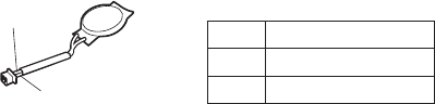
Checking the ac adapter
You are here because the computer fails only when the ac
adapter is used.
v If the power problem occurs only when the port
replicator is used, replace the port replicator.
v If the power-on indicator does not turn on, check the
power cord of the ac adapter for correct continuity and
installation.
v If the computer does not charge during operation, go to
″Checking operational charging.″
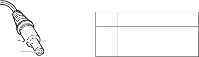
To check the ac adapter, do the following:
1. Unplug the ac adapter cable from the computer.
2. Measure the output voltage at the plug of the ac
adapter cable. See the following figure:
2
1
(16-10V)
Pin Voltage (V dc)
1 +15.5 to +17.0
2 Ground
3. If the voltage is not correct, replace the ac adapter.
4. If the voltage is acceptable, do the following:
v Replace the system board.
v If the problem persists, go to “Product overview” on
page 45.
Note: Noise from the ac adapter does not always indicate
a defect.
Checkout guide
General descriptions 39
Checking operational charging
To check whether the battery charges properly during
operation, use a discharged battery pack or a battery pack
that has less than 50% of the total power remaining when
installed in the computer.
Perform operational charging. If the battery status indicator
or icon does not turn on, remove the battery pack and let it
return to room temperature. Reinstall the battery pack. If
the charge indicator or icon still does not turn on, replace
the battery pack.
If the charge indicator still does not turn on, replace the
system board. Then reinstall the battery pack. If it is still
not charged, go to the next section.
Checking the battery pack
Battery charging does not start until the Power Meter
shows that less than 95% of the total power remains;
under this condition the battery pack can charge to 100%
of its capacity. This protects the battery pack from being
overcharged or from having a shortened life.
To check your battery, move your cursor to the Power
Meter icon in the icon tray of the Windows taskbar and
wait for a moment (but do not click), and the percentage of
battery power remaining is displayed. To get detailed
information about the battery, double-click the Power Meter
icon.
Note: If the battery pack becomes hot, it may not be able
to charge. Remove it from the computer and leave it
at room temperature for a while. After it cools down,
reinstall and recharge it.
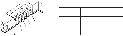
To check the battery pack, do the following:
1. Power off the computer.
2. Remove the battery pack and measure the voltage
between battery terminals 1 (+) and 5 (−). See the
following figure:
2
3
4
5(-)
1(+)
Terminal Voltage (V dc)
1 + 0 to + 12.6
5 Ground (−)
3. If the voltage is less than +11.0 V dc, the battery pack
has been discharged.
Checkout guide
40 T40/T40p, T41/T41p, T42/T42p
Note: Recharging will take at least 3 hours, even if the
indicator does not turn on.
If the voltage is still less than +11.0 V dc after
recharging, replace the battery.
4. If the voltage is more than +11.0 V dc, measure the
resistance between battery terminals 4 and 5. The
resistance must be 4 to 30 K .
If the resistance is not correct, replace the battery
pack. If the resistance is correct, replace the system
board.
Checking the backup battery
Do the following:
1. Power off the computer, and unplug the ac adapter
from it.
2. Turn the computer upside down.
3. Remove the battery pack (see “1010 Battery pack for
14.1-in. LCD models” on page 71).
4. Remove the backup battery (see “Checking the battery
pack” on page 40).
5. Measure the voltage of the backup battery. See the
following figure.
Red (+)
Black (-)
Wire Voltage (V dc)
Red +2.5 to +3.2
Black Ground
v If the voltage is correct, replace the system board.
v If the voltage is not correct, replace the backup battery.
v If the backup battery discharges quickly after
replacement, replace the system board.
Checkout guide
General descriptions 41
Checkout guide
42 T40/T40p, T41/T41p, T42/T42p

ThinkPad T40/T40p, T41/T41p,
T42/T42p Series
Product overview . . . . . . . . . . . .45
Specifications . . . . . . . . . . . .45
Status indicators . . . . . . . . . . .50
FRU tests . . . . . . . . . . . . .53
Fn key combinations . . . . . . . . . .54
Symptom-to-FRU index . . . . . . . . . .58
Numeric error codes . . . . . . . . . .58
Error messages . . . . . . . . . . .62
Beep symptoms . . . . . . . . . . .63
No-beep symptoms . . . . . . . . . .63
LCD-related symptoms . . . . . . . . .64
Intermittent problems . . . . . . . . . .65
Undetermined problems . . . . . . . . .65
FRU replacement notices . . . . . . . . .66
Screw notices . . . . . . . . . . . .66
Retaining serial numbers . . . . . . . . .67
Restoring the serial number of the system unit 67
Retaining the UUID . . . . . . . . .68
Reading or writing the ECA information . . .68
Removing and replacing a FRU . . . . . . . .70
1010 Battery pack for 14.1-in. LCD models . . .71
1020 Battery pack for 15.0-in. LCD models . . .73
1030 Ultrabay Slim device . . . . . . . .74
1040 Hard disk drive . . . . . . . . . .75
1050 DIMM (optional) . . . . . . . . .77
1060 Keyboard . . . . . . . . . . .79
1070 DIMM (standard) . . . . . . . . .83
1080 Modem daughter card (MDC/MDC-2) . . .84
1090 Bluetooth/Modem daughter card
(BMDC/BMDC-2) . . . . . . . . . .86
1100 Palm rest or Palm rest with fingerprint sensor
(for 14.1-in. LCD models) . . . . . . . .88
1110 Keyboard bezel or Keyboard bezel with
fingerprint sensor (for 15.0-in. LCD models) . .91
1120 Mini PCI adapter . . . . . . . . .97
1130 Fan assembly . . . . . . . . . . 101
1140 Backup battery for 14.1-in. LCD models 106
1150 Backup battery for 15.0-in. LCD models 108
1160 Speaker assembly . . . . . . . .110
1170 Keyboard bezel for 14.1-in. LCD models 112
1180 PC Card slot assembly for 14.1-in. LCD
models . . . . . . . . . . . . .114
1190 PC Card slot assembly for 15.0-in. LCD
models . . . . . . . . . . . . .116
1200 LCD assembly for 14.1-in. LCD models 118
1210 LCD assembly for 15.0-in. LCD models 123
1220 CPU . . . . . . . . . . . . 128
1230 Ultrabay Slim guide rail assembly for 14.1-in.
LCD models . . . . . . . . . . . 129
© Lenovo 2006. Portions © IBM Corp. 2006. 43
1240 Ultrabay Slim guide rail assembly for 15.0-in.
LCD models . . . . . . . . . . . 131
1250 VGA and Ultrabay Slim device eject button
cable . . . . . . . . . . . . . 134
1260 System board and base cover for 14.1-in.
LCD models . . . . . . . . . . . 136
1270 System board, interposer card, and base
cover for 15.0-in. LCD models . . . . . . 145
2010 LCD front bezel for 14.1-in. LCD models 153
2020 LCD front bezel for 15.0-in. LCD models 155
2030 Inverter card for 14.1-in. LCD models . . . 157
2040 Inverter card for 15.0-in. LCD models . . . 159
2050 Wireless antenna assemblies, LCD panel,
LCD cable assembly, hinges, and LCD cover for
14.1-in. LCD models . . . . . . . . . 160
2060 Wireless antenna assemblies, LCD panel,
LCD cable assembly, hinges, and LCD cover for
15.0-in. LCD models . . . . . . . . . 175
3010 ThinkPad Dock II PCI cover . . . . . . 182
3020 ThinkPad Dock II top cover . . . . . . 183
Locations . . . . . . . . . . . . . . 186
Front view . . . . . . . . . . . . 186
Rear view . . . . . . . . . . . . . 188
Bottom view . . . . . . . . . . . . 189
Parts list . . . . . . . . . . . . . . 190
Overall . . . . . . . . . . . . . 191
14.1-in. LCD FRUs . . . . . . . . . . 220
14.1-in. XGA TFT . . . . . . . . . 221
14.1-in. SXGA+ TFT . . . . . . . . 226
15.0-in. LCD FRUs . . . . . . . . . . 230
15.0-in. XGA TFT . . . . . . . . . 231
15.0-in. SXGA+ IPS TFT . . . . . . . 232
15.0-in. UXGA IPS TFT . . . . . . . . 234
Keyboard . . . . . . . . . . . . . 235
Recovery CDs . . . . . . . . . . . 237
Windows XP Professional (for T40/T40p series) 237
Windows XP Professional (for T41/T41p series) 238
Windows XP Professional (for T42/T42p series) 239
Windows 2000 (for T40/T40p series) . . . . 241
Windows 2000 (for T41 series) . . . . . 242
Windows XP Home Edition (for T42/T42p
series) . . . . . . . . . . . . 242
Miscellaneous parts . . . . . . . . . . 243
AC adapters . . . . . . . . . . . . 246
Optional FRUs . . . . . . . . . . . 247
Common parts list . . . . . . . . . . 248
Tools . . . . . . . . . . . . . 248
Power cords (system) . . . . . . . . 248
Power cords (ThinkPad Dock II) . . . . . 249
Notices . . . . . . . . . . . . . . 250
Trademarks . . . . . . . . . . . . . 252
44 T40/T40p, T41/T41p, T42/T42p

Product overview
This section presents the following product-unique
information:
v “Specifications”
v “Status indicators” on page 50
v “FRU tests” on page 53
v “Fn key combinations” on page 54
Specifications
The following table lists the specifications of the ThinkPad
T40/ T40p, T41/T41p, T42/T42p series:
Feature Description
Processor T40/T40p series:
v Intel
®
Pentium
®
M processor 1.3 GHz,
1-MB L2 cache
v Intel Pentium M processor 1.5 GHz,
1-MB L2 cache
v Intel Pentium M processor 1.6 GHz,
1-MB L2 cache
T41/T41p series:
v Intel Pentium M processor 1.4 GHz,
1-MB L2 cache
v Intel Pentium M processor 1.6 GHz,
1-MB L2 cache
v Intel Pentium M processor 1.7 GHz,
1-MB L2 cache
T42/T42p series:
v Intel Pentium M processor 1.5 GHz,
1-MB L2 cache
v Intel Pentium M processor 715 (1.5
GHz), 2-MB L2 cache
v Intel Pentium M processor 725 (1.6
GHz), 2-MB L2 cache
v Intel Pentium M processor 735 (1.7
GHz), 2-MB L2 cache
v Intel Pentium M processor 745 (1.8
GHz), 2-MB L2 cache
v Intel Pentium M processor 755 (2.0
GHz), 2-MB L2 cache
(continued)
Product overview
ThinkPad T40/T40p, T41/T41p, T42/T42p Series 45

Feature Description
Bus architecture T40/T40p series:
v 400-MHz PSB (Processor System Bus)
v 266-MHz DDR SDRAM (PC2100)
v HUB link
v PCI bus
v LPC bus
T41/T41p, T42/T42 series:
v 400-MHz PSB
v 333-MHz DDR SDRAM (PC2700)
v HUB link
v PCI bus
v LPC bus
Graphic memory
chip
T40/T40p series:
v 16-MB DDR SDRAM (ATI M6-16)
v 32-MB DDR SDRAM (ATI M7-32)
v 32-MB DDR SDRAM (ATI M9-32)
v 64-MB DDR SDRAM (ATI M9 GL-64)
T41/T41p series:
v 32-MB DDR SDRAM (ATI M7-32)
v 32-MB DDR SDRAM (ATI M9-32)
v 128-MB DDR SDRAM (ATI M10 GL-128)
T42/T42p series:
v 32-MB DDR SDRAM (ATI M7-32)
v 64-MB DDR SDRAM (ATI M9-64)
v 64-MB DDR SDRAM (ATI M10-64)
v 128-MB DDR SDRAM (ATI M10 GL-128)
Display v 14.1-inch, 16M colors, XGA (1024 × 768
resolution) TFT color LCD
v 14.1-inch, 16M colors, SXGA+ (1400 ×
1050 resolution) TFT color LCD
v 15.0-inch, 16M colors, XGA (1024 × 768
resolution) TFT color LCD
v 15.0-inch, 16M colors, SXGA+ (1400 ×
1050 resolution) IPS (in-plane switching)
TFT color LCD
v 15.0-inch, 16M colors, UXGA (1600 ×
1200 resolution) IPS TFT color LCD
(continued)
Product overview
46 T40/T40p, T41/T41p, T42/T42p

Feature Description
Standard memory T40/T40p series:
v 256-MB DDR SDRAM SO-DIMM
(PC2100) card × 1
v 512-MB DDR SDRAM SO-DIMM
(PC2100) card × 1
v 1 GB-DDR SDRAM SO-DIMM (PC2100)
card × 1
T41/T41p, T42/T42p series:
v 256-MB DDR SDRAM SO-DIMM
(PC2700) card × 1
v 512-MB DDR SDRAM SO-DIMM
(PC2700) card × 1
v 1-GB DDR SDRAM SO-DIMM (PC2700)
card × 1
Optional memory T40/T40p series:
v 128-MB DDR SDRAM SO-DIMM
(PC2100) card
v 256-MB DDR SDRAM SO-DIMM
(PC2100) card
v 512-MB DDR SDRAM SO-DIMM
(PC2100)
v 1-GB DDR SDRAM SO-DIMM (PC2100)
T41/T41p, T42/T42p series:
v 128-MB DDR SDRAM SO-DIMM
(PC2700) card × 1
v 256-MB DDR SDRAM SO-DIMM
(PC2700) card × 1
v 512-MB DDR SDRAM SO-DIMM
(PC2700) card × 1
v 1-GB DDR SDRAM SO-DIMM (PC2700)
card × 1
(maximum of 2048 MB)
CMOS RAM v 242 bytes
(continued)
Product overview
ThinkPad T40/T40p, T41/T41p, T42/T42p Series 47

Feature Description
Hard disk drive v 20.0 GB, 4200 rpm, 9.5 mm high, IDE
interface (supported by CTO)
v 30.0 GB, 4200 rpm, 9.5 mm high, IDE
interface
v 40.0 GB, 5400 rpm, 9.5 mm high, IDE
interface
v 60.0 GB, 4200 rpm, 9.5 mm high, IDE
interface
v 60.0 GB, 5400 rpm, 9.5 mm high, IDE
interface
v 60.0 GB, 7200 rpm, 9.5 mm high, IDE
interface
v 80.0 GB, 4200 rpm, 9.5 mm high, IDE
interface
v 80.0 GB, 5400 rpm, 9.5 mm high, IDE
interface
Supported hard disk drives are depend on
the model.
Ultrabay Slim device
(standard)
T40/T40p, T41/T41p series:
v DVD drive, 9.5 mm high
v DVD/CD-RW combo drive, 9.5 mm high
T42/T42p series:
v DVD drive, 9.5 mm high
v DVD/CD-RW combo drive, 9.5 mm high
v DVD-RAM/RW drive, 9.5 mm high
Fingerprint sensor Some models
I/O port v External monitor connector
v Stereo headphone jack
v Monaural microphone jack
v Infrared port
v Parallel connector
v Docking connector
v RJ11 connector
v RJ45 connector
v TV-out connector (S-Video)
v Universal serial bus (USB) connector × 2
(compatible with USB 1.1 and 2.0)
Internal modem v 56.6 Kbps
Audio v Built-in stereo speakers
v Software control volume
Infrared transfer v IrDA 1.1
Ethernet (on the
system board)
T40/T40p, T41/T41p series:
v 10/100Base Ethernet
v Gigabit Ethernet
T42/T42p series:
v Gigabit Ethernet
(continued)
Product overview
48 T40/T40p, T41/T41p, T42/T42p

Feature Description
Mini PCI adapter T40/T40p series:
v ThinkPad Dual-Band 11a/b Wi-Fi
Wireless Mini PCI Adapter
v Cisco Aironet Wireless 802.11b
v Intel PRO/Wireless LAN 2100 3B Mini
PCI Adapter
T41/T41p series:
v Cisco Aironet Wireless 802.11b
v Intel PRO/Wireless LAN 2100 3B Mini
PCI Adapter
v ThinkPad 11a/b/g Wireless LAN Mini
PCI Adapter
T42/T42p series:
v Cisco Aironet Wireless 802.11b
v Intel PRO/Wireless LAN 2100 3B Mini
PCI Adapter
v ThinkPad 11a/b/g Wireless LAN Mini
PCI Adapter
v Intel PRO Wireless 2200BG Mini-PCI
Adapter
v ThinkPad 11b/g Wireless LAN Mini PCI
Adapter
v ThinkPad 11a/b/g Wireless LAN Mini
PCI Adapter II
v Intel PRO Wireless 2915ABG Mini-PCI
Adapter
PC Card v One Type-III
v Two Type-II
Communication
daughter card
(CDC)
T40/T40p, T41/T41p series:
v V.90 modem daughter card (MDC)
v ThinkPad Integrated Bluetooth with 56K
Modem (BMDC)
T42/T42p series:
v ThinkPad Integrated 56K Modem
(MDC-2)
v ThinkPad Integrated Bluetooth III with
56K Modem (BMDC-2)
Touch pad v UltraNav
ThinkLight Yes
Battery v Li-ion battery (6 cells)
v Li-ion battery (9 cells)
v Ultrabay Slim Li Polymer battery (option)
AC adapter v 72-watt type
Preinstalled
operating system
T40/T40p, T41/T41p series:
v Windows XP Professional
v Windows 2000
T42/T42p series:
v Windows XP Professional
Product overview
ThinkPad T40/T40p, T41/T41p, T42/T42p Series 49
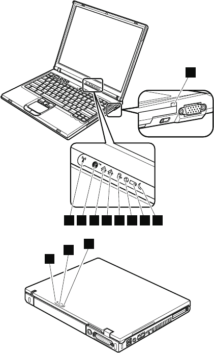
Status indicators
The system status indicators show the status of the
computer, as follows:
2223242526272829
1
2
8
3
Product overview
50 T40/T40p, T41/T41p, T42/T42p
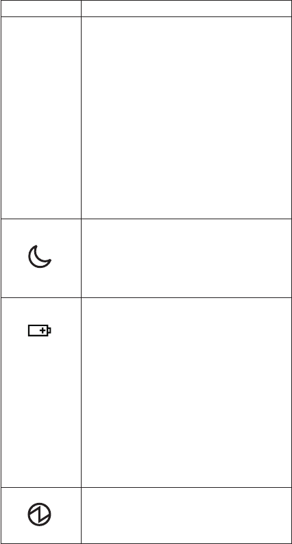
Indicator Meaning
1 Ultrabay
Slim status
Green:
An Ultrabay Slim device is installed and in
use.
Blinking green:
An Ultrabay Slim device is in the process
of being detached.
Turn off:
An Ultrabay Slim device is ready to be
attached or detached.
Note: If you are using Windows 2000, the
Ultrabay Slim status indicator does not blink
while an Ultrabay Slim device is being
detached. Instead, a message box pops up
when the process is completed; then the
indicator turns off.
2 Standby
status
Green:
The computer is in standby mode.
Blinking green:
The computer is entering standby mode or
hibernation mode, or is resuming normal
operation.
3 Battery
status
Green:
The battery is in use and has enough
power. The ac adapter has charged the
battery completely.
Blinking green:
The battery is being charged, but still has
enough power to operate. (At regular
intervals, the indicator light turns off briefly.)
Orange:
The battery is being charged, but the
battery power is still low.
Blinking orange:
The battery needs to be charged. When
the indicator starts blinking orange, the
computer beeps three times.
4 Power on
Green:
The computer is on and ready to use. This
indicator stays lit whenever the computer is
on and is not in standby mode.
(continued)
Product overview
ThinkPad T40/T40p, T41/T41p, T42/T42p Series 51
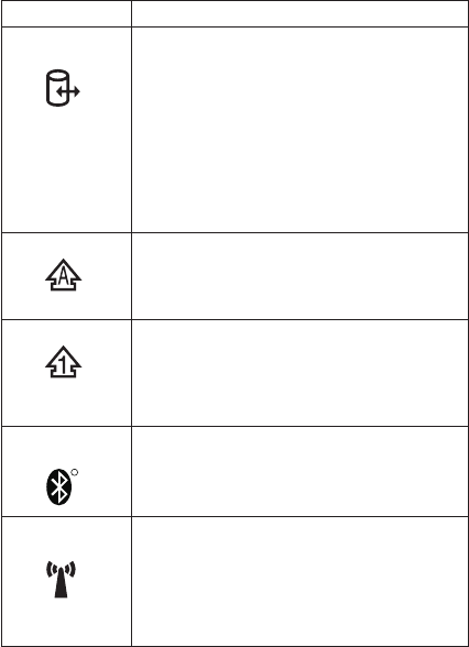
Indicator Meaning
5 Drive in
use
Green:
Data is being read from or written to the
hard disk drive, the diskette drive, or the
drive in the Ultrabay Slim device. When
this indicator is on, do not put the computer
into standby mode or turn off the computer.
Note: Do not move the system while the
green drive-in-use light is on. Sudden physical
shock could cause drive errors.
6 Caps lock
Green:
Caps Lock mode is enabled. To enable or
disable Caps Lock mode, press the Caps
Lock key.
7 Num lock
Green:
The numeric keypad on the keyboard is
enabled. To enable or disable the keypad,
press and hold the Shift key, and press the
NumLk (ScrLk) key.
8 Bluetooth
status
R
Green:
Bluetooth wireless is operational. This
indicator is on when Bluetooth wireless is
on and not in suspend mode.
9 Wireless
status
Green:
The wireless feature (the IEEE 802.11
standard) is on, and the radio link is ready
for use.
Blinking green:
Data is being transmitted.
Product overview
52 T40/T40p, T41/T41p, T42/T42p

FRU tests
The following table shows the test for each FRU.
FRU Applicable test
System board 1. Diagnostics --> CPU/Coprocessor
2. Diagnostics --> Systemboard
3. If the docking station or the port replicator
is attached to the ThinkPad computer,
undock it. Place the computer on a
horizontal surface, and run Diagnostics -->
Other Devices --> HDD Active Protection
Test.
Note: Do not apply any physical shock to
the computer while the test is running.
Power Diagnostics --> Other Devices --> AC
Adapter, Battery 1 (Battery 2)
LCD unit 1. Diagnostics --> Video Adapter
2. Interactive Tests --> Video
Modem
daughter card
(MDC or
BMDC)
1. Make sure the modem is set up correctly.
2. Replace the modem jack and the modem
card in turn, and run the following tests in
Diagnostics --> Communication:
a. Lucent Soft Modem Loopback
b. Lucent Soft Modem Dialtone
c. Conexant Smart Modem Interrupt
d. Conexant Smart Modem Dialtone
Audio 1. Interactive Tests --> Internal Speaker
2. Diagnostics --> Other Devices --> Analog
Devices AC97 CODEC Test
Speaker Interactive Tests --> Internal Speaker
PC Card slots 1. Diagnostics --> Systemboard --> PCMCIA
2. Insert a PC Card Wrap Plug into every PC
Card slot, and run Diagnostics -->
Systemboard --> PCMCIA External Loop
Keyboard 1. Diagnostics --> Systemboard -->
Keyboard
2. Interactive Tests --> Keyboard
Hard disk drive Diagnostics --> Fixed Disks
Diskette drive 1. Diagnostics --> Diskette Drives
2. Interactive Tests --> Diskette
DVD drive or
DVD/CD-RW
combo drive
1. Diagnostics --> Other Devices -->
CD-ROM/DVD
2. Interactive Tests --> CD-ROM/DVD Test
(continued)
Product overview
ThinkPad T40/T40p, T41/T41p, T42/T42p Series 53

FRU Applicable test
Memory 1. If two DIMMs are installed, remove one of
them and run Diagnostics --> Memory
Test—Quick.
2. If the problem does not recur, return the
DIMM to its place, remove the other one,
and run the test again.
3. If the test does not detect the error, run
Diagnostics --> Memory Test—Full.
Fan 1. Turn on the computer and check the air
turbulence at the louver near the PC Card
slot.
2. Run Diagnostics --> Other Devices -->
Fan.
TrackPoint or
pointing device
If the TrackPoint does not work, check the
configuration as specified in the ThinkPad
Configuration program. If the TrackPoint is
disabled, select Automatic to enable it.
After you use the TrackPoint, the pointer may
drift on the screen for a short time. This drift
can occur when a slight, steady pressure is
applied to the TrackPoint pointer. This symptom
is not a hardware problem. If the pointer stops
after a short time, no service action is
necessary.
If enabling the TrackPoint does not correct the
problem, continue with the following:
v Interactive Tests --> Mouse
Touch Pad If the Touch Pad does not work, check the
configuration as specified in the ThinkPad
Configuration program. If the Touch Pad is
disabled, select Automatic to enable it. If
enabling the Touch Pad does not correct the
problem, continue with the following:
v Interactive Tests --> Mouse
Fn key combinations
The following table shows the function of each combination
of Fn with a function key.
Key
combination
Description
Fn+F1 Reserved.
Fn+F2 Reserved.
Fn+F3 Turn off the computer display, leaving the
screen blank. To turn the computer display on
again, press any key or press the TrackPoint
pointing stick.
(continued)
Product overview
54 T40/T40p, T41/T41p, T42/T42p

Key
combination
Description
Fn+F4 Put the computer in standby mode. To return to
normal operation, press the Fn key only,
without pressing a function key.
Notes:
1. This mode is called suspend mode in
Windows NT.
2. In Windows 2000 and Windows XP, this
combination of keys functions as a sleep
button. The setting can be changed so that
pressing it puts the computer into
hibernation mode or even shuts the
computer down.
Fn+F5 Control the power source of the built-in
Bluetooth wireless device. This combination of
the keys functions as a toggle switch of the
power state.
Note: In Windows 98, Windows 2000, or
Windows XP, this combination of keys enables
or disables the built-in wireless networking
features (the IEEE 802.11 standard) and the
Bluetooth wireless features. To use this
function, the following drivers must be installed.
v ThinkPad Power Management driver
v OnScreen Display utility
v Wireless device drivers
Fn+F6 Reserved.
Fn+F7 Switch a display output location
v External monitor (CRT display)
v Computer display and external monitor (LCD
+ CRT display)
v Computer display (LCD)
Note: For any operating system other than
Windows 2000 or Windows XP, no additional
procedure is needed; just press Fn+F7.
Notes:
1. This function does not work when different
desktop images are displayed on the
computer display and the external monitor
(the Extend desktop function).
2. This function does not work while a DVD
movie or a video clip is playing.
3. For Windows 2000 or Windows XP, a
hotkey application might take over the
switching function.
(continued)
Product overview
ThinkPad T40/T40p, T41/T41p, T42/T42p Series 55

Key
combination
Description
Fn+F8 Note: This function is not supported in
Windows 2000 and Windows XP.
If the image displayed on the computer is
smaller than the physical display, switch the
computer screen size between expanded mode
and normal mode.
Fn+F9 Open the ThinkPad EasyEject Utility screen.
Buttons for the following choices are displayed:
v Eject ThinkPad PC from Dock: This button
is displayed only if the ThinkPad computer
has been attached to a ThinkPad Dock II.
The computer can be detached from the
ThinkPad Dock II.
v Eject ThinkPad PC from Mini Dock: This
button is displayed only if the ThinkPad
computer has been docked in a ThinkPad
Mini Dock and one or more USB devices
have been connected to the ThinkPad Mini
Dock. You can stop and remove all the USB
devices safely by clicking the button.
Note: If a diskette drive is connected to the
external-diskette-drive connector of the
ThinkPad Mini Dock, you cannot connect a
USB diskette drive.
v Run EasyEject Actions: This button is used
to select, stop, or remove external devices
connected to the ThinkPad computer.
v Configure EasyEject Actions: Opens the
ThinkPad EasyEject Utility main window.
v Fn+F9 Settings: Configures the settings for
the Fn+F9 function.
You can use this utility to stop and remove all
ejectable devices connected to the ThinkPad
computer, the ThinkPad Mini Dock, or the
ThinkPad Port Replicator II. You cannot use it
to detach the computer from the ThinkPad Mini
Dock or the ThinkPad Port Replicator II.
Note: This function is supported only in
Windows 2000 and Windows XP.
Fn+F10 Reserved.
Fn+F11 Reserved.
(continued)
Product overview
56 T40/T40p, T41/T41p, T42/T42p

Key
combination
Description
Fn+F12 Put the computer into hibernation mode. To
return to normal operation, press the power
button for less than four seconds.
Note: To use Fn+F12 for hibernation in
Windows 2000 or Windows XP, you must have
the PM device driver installed on the computer.
Fn+PgUp Turn the ThinkLight on or off.
Note: This function is supported only on the
ThinkPad computers that have the ThinkLight.
The on or off status of the ThinkLight is shown
on the screen for a few seconds when you
press Fn+PgUp.
Fn+Home The computer display becomes brighter.
Fn+End The computer display becomes dimmer.
Fn+Spacebar Enable the FullScreen Magnifier function.
Product overview
ThinkPad T40/T40p, T41/T41p, T42/T42p Series 57

Symptom-to-FRU index
The symptom-to-FRU index in this section lists symptoms
and errors and their possible causes. The most likely
cause is listed first, in boldface type.
Note: Do the FRU replacement or other actions in the
sequence shown in the column headed “FRU or
action, in sequence.” If replacing a FRU does not
solve the problem, put the original part back in the
computer. Do not replace a nondefective FRU.
This index can also help you determine, during regular
servicing, what FRUs are likely to need to be replaced
next.
A numeric error is displayed for each error detected in
POST or system operation. In the displays, n can be any
number.
If no numeric code is displayed, check the narrative
descriptions of symptoms. If the symptom is not described
there, go to “Intermittent problems” on page 65.
Note
For a device not supported by diagnostic codes in
the ThinkPad notebook computers, see the manual
for that device.
Numeric error codes
Symptom or error FRU or action, in sequence
0175
Bad CRC1, stop POST
task—The EEPROM checksum
is not correct.
System board.
0176
System Security—The system
has been tampered with.
1. Run BIOS Setup Utility,
and save the current
setting by pressing F10.
2. System board.
0177
Bad SVP data, stop POST
task—The checksum of the
supervisor password in the
EEPROM is not correct.
System board
0182
Bad CRC2. Enter BIOS Setup
and load Setup defaults.—The
checksum of the CRS2 setting
in the EEPROM is not correct.
1. Run BIOS Setup Utility.
Press F9, and Enter to
load the default setting.
Then save the current
setting by pressing F10.
2. System board.
Symptom-to-FRU index
58 T40/T40p, T41/T41p, T42/T42p

Symptom or error FRU or action, in sequence
0185
Bad startup sequence settings.
Enter BIOS Setup and load
Setup defaults.
1. Run BIOS Setup Utility.
Press F9, and Enter to
load the default setting.
Then save the current
setting by pressing F10.
0187
EAIA data access error—The
access to EEPROM is failed.
System board.
0188
Invalid RFID Serialization
Information Area.
System board.
0189
Invalid RFID configuration
information area—The
EEPROM checksum is not
correct.
System board.
0190
Critical low-battery error
1. Charge the battery pack.
2. Battery pack.
0191
System Security—Invalid
Remote Change requested.
1. Run BIOS Setup Utility,
and then save current
setting by pressing F10.
2. System board.
0192
System Security— IBM
Embedded Security hardware
tamper detected.
System board.
0199
System Security—IBM Security
password retry count exceeded.
1. Run BIOS Setup Utility,
and then save the current
setting by pressing F10.
2. System board.
01C8
Two or more modem devices
are found. Remove all but one
of them. Press <Esc> to
continue.
1. Remove either a Mini-PCI
Card or a modem
daughter card. Otherwise,
press Esc to ignore the
warning message.
2. System board.
01C9
More than one Ethernet devices
are found. Remove one of
them. Press <Esc> to continue.
1. Remove the Ethernet
device that you installed;
or press Esc to ignore the
warning message.
2. System board.
0200
Hard disk error—The hard disk
is not working.
1. Reseat the hard disk
drive.
2. Load Setup Defaults in
BIOS Setup Utility.
3. Hard disk drive.
4. System board.
021x
Keyboard error.
Run interactive tests of the
keyboard and the auxiliary
input device.
Symptom-to-FRU index
ThinkPad T40/T40p, T41/T41p, T42/T42p Series 59

Symptom or error FRU or action, in sequence
0220
Monitor type error—Monitor
type does not match the one
specified in CMOS.
Load Setup Defaults in BIOS
Setup Utility.
0230
Shadow RAM error—Shadow
RAM fails at offset nnnn.
System board.
0231
System RAM error—System
RAM fails at offset nnnn.
1. DIMM.
2. System board.
0232
Extended RAM error—
Extended RAM fails at offset
nnnn.
1. DIMM.
2. System board.
0250
System battery error—System
battery is dead.
Replace the backup battery
and run BIOS Setup Utility to
reset the time and date.
0251
System CMOS checksum
bad— Default configuration
used.
Replace the backup battery
and run BIOS Setup Utility to
reset the time and date.
0252
Password checksum bad—The
password is cleared.
Reset the password by
running BIOS Setup Utility.
0260
System timer error.
1. Replace the backup
battery and run BIOS
Setup Utility to reset the
time and date.
2. System board.
0270
Real-time clock error.
1. Replace the backup
battery and run BIOS
Setup Utility to reset the
time and date.
2. System board.
0271
Date and time error—Neither
the date nor the time is set in
the computer.
Run BIOS Setup Utility to
reset the time and date.
0280
Previous boot incomplete—
Default configuration used.
1. Load “Setup Default” in
BIOS Setup Utility.
2. DIMM.
3. System board.
02F5
DMA test failed.
1. DIMM.
2. System board.
02F6
Software NMI failed
1. DIMM.
2. System board.
02F7
Fail-safe timer NMI failed
1. DIMM.
2. System board.
1802
Unauthorized network card is
plugged in—Turn off and
remove the miniPCI network
card.
1. Remove Mini PCI network
card.
2. System board.
Symptom-to-FRU index
60 T40/T40p, T41/T41p, T42/T42p

Symptom or error FRU or action, in sequence
1803
Unauthorized daughter card is
plugged in—Turn off and
remove the daughter card.
1. Remove the daughter
card that you installed.
2. System board.
1810
Hard disk partition layout error.
1. If the Access IBM
Predesktop Area has been
previously disabled, then
go to the BIOS Setup
Utility by pressing F1 to
open the BIOS Setup
Utility. Select Security -->
Predesktop Area -->
Access IBM Predesktop
Area. Set this item to
Disabled. Save and exit.
2. If the Access IBM
Predesktop Area has not
been previously disabled,
press Enter to load Access
IBM Predesktop Area. Then
run RECOVER TO
FACTORY CONTENTS in
Access IBM Predesktop
Area.
3. If item 2 failed, press F3 in
the Welcome screen in
RECOVER TO FACTORY
CONTENTS. Run FDISK,
and then delete all
partitions. Run RECOVER
TO FACTORY CONTENTS
in Access IBM Predesktop
Area again.
4. If item 3 failed, select
CD-ROM boot in Startup in
Access IBM Predesktop
Area. Boot from the
Recovery CD and perform
full recovery from it.
5. If item 4 failed, replace the
hard disk drive.
2000
IBM Hard Drive Active
Protection sensor diagnostics
failed.
Press <Esc> to continue.
Press <F1> to enter SETUP
1. Undock docking station or
port replicator if it is
attached to the ThinkPad
computer, and place the
computer on a horizontal
surface. Do not apply any
physical shock to the
computer.
2. Run Diagnostics --> Other
Devices --> HDD Active
Protection Test.
Symptom-to-FRU index
ThinkPad T40/T40p, T41/T41p, T42/T42p Series 61

Error messages
Symptom or error FRU or action, in sequence
Device address conflict. 1. Load “Setup Defaults” in
the BIOS Setup Utility.
2. Backup battery.
3. System board.
Allocation error for device. 1. Load “Setup Defaults” in
the BIOS Setup Utility.
2. Backup battery.
3. System board.
Failing bits: nnnn. 1. DIMM.
2. System board.
Invalid system configuration
data.
1. DIMM.
2. System board.
I/O device IRQ conflict. 1. Load “Setup Defaults” in
the BIOS Setup Utility.
2. Backup battery.
3. System board.
Operating system not found. 1. Check that the operating
system has no failure and is
installed correctly.
2. Enter the BIOS Setup
Utility and see whether
the hard disk drive and
the diskette drive are
properly identified.
3. Reseat the hard disk drive.
4. Reinstall the operating
system.
5. Diskette drive.
6. Hard disk drive.
7. System board.
Hibernation error. 1. Restore the system
configuration to what it
was before the computer
entered hibernation mode.
2. If memory size has been
changed, re-create the
hibernation file.
Fan error. Fan.
Thermal sensing error. System board.
Authentication of system
services failed. Press <Esc> to
resume.
The Predesktop Area in the
HDD is corrupted. Restore it
from a recovery CD.
Symptom-to-FRU index
62 T40/T40p, T41/T41p, T42/T42p

Beep symptoms
Symptom or error FRU or action, in sequence
One beep and a blank,
unreadable, or flashing LCD.
1. Reseat the LCD
connector.
2. LCD assembly.
3. External CRT.
4. System board.
One long and two short beeps,
and a blank or unreadable
LCD.
1. System board.
2. LCD assembly.
3. DIMM.
Two short beeps with error
codes.
POST error. See “Numeric
error codes” on page 58.
Two short beeps and a blank
screen.
1. System board.
2. DIMM.
Three short beeps, pause,
three more short beeps, and
one short beep.
1. DIMM.
2. System board
One short beep, pause, three
short beeps, pause, three more
short beeps, and one short
beep.
Only the cursor appears. Reinstall the operating
system.
Four cycles of four short beeps
and a blank screen.
System board (security chip)
Five short beeps and a blank
screen.
System board
No-beep symptoms
Symptom or error FRU or action, in sequence
No beep, power-on indicator
on, LCD blank, and no POST.
1. Make sure that every
connector is connected
tightly and correctly.
2. DIMM.
3. System board.
No beep, power-on indicator
on, and LCD blank during
POST.
1. Reseat DIMM.
2. System board.
The power-on password prompt
appears.
A power-on password or a
supervisor password is set.
Type the password and press
Enter.
The hard-disk password prompt
appears.
A hard-disk password is set.
Type the password and press
Enter.
The DOS full screen looks
smaller than it should.
Start the ThinkPad
Configuration program and set
the Screen expansion
function.
Symptom-to-FRU index
ThinkPad T40/T40p, T41/T41p, T42/T42p Series 63

LCD-related symptoms
Important
The TFT LCD for the notebook computer contains
many thin-film transistors (TFTs). The presence of a
small number of dots that are missing, discolored, or
always lighted is characteristic of TFT LCD
technology, but excessive pixel problems can cause
viewing concerns. The LCD should be replaced if
the number of missing, discolored, or lighted dots in
any background is:
v XGA: 8 or more bright dots, 8 or more dark dots,
or a total of 9 or more bright and dark dots.
v SXGA+: 11 or more bright dots, 13 or more dark
dots, or a total of 16 or more bright and dark
dots.
v UXGA: 11 or more bright dots, 16 or more dark
dots, or a total of 16 or more bright and dark
dots.
Note: A bright dot means a pixel is always on
(white or color.) A dark dot means a pixel is
always off (black color.)
Symptom or error FRU or action, in sequence
No beep, power-on indicator
on, and a blank LCD during
POST.
System board.
v LCD backlight not working.
v LCD too dark.
v LCD brightness cannot be
adjusted.
v LCD contrast cannot be
adjusted.
1. Reseat the LCD
connectors.
2. LCD assembly.
3. System board.
v LCD screen unreadable.
v Characters missing pixels.
v Screen abnormal.
v Wrong color displayed.
1. See important note for
“LCD-related symptoms.”
2. Reseat all LCD connectors.
3. LCD assembly.
4. System board.
Horizontal or vertical lines
displayed on LCD.
LCD assembly.
Symptom-to-FRU index
64 T40/T40p, T41/T41p, T42/T42p
Intermittent problems
Intermittent system hang problems can be due to a variety
of causes that have nothing to do with a hardware defect,
such as cosmic radiation, electrostatic discharge, or
software errors. FRU replacement should be considered
only when a problem recurs.
When analyzing an intermittent problem, do the following:
1. Run the diagnostic test for the system board in loop
mode at least 10 times.
2. If no error is detected, do not replace any FRUs.
3. If any error is detected, replace the FRU shown by the
FRU code. Rerun the test to verify that no more errors
exist.
Undetermined problems
If the diagnostic tests did not identify the adapter or device
that has failed, if wrong devices are installed, or if the
system simply is not operating, follow these procedures to
isolate the failing FRU (do not isolate FRUs that have no
defects).
Verify that all attached devices are supported by the
computer.
Verify that the power supply being used at the time of the
failure is operating correctly. (See “Power system
checkout” on page 39.)
1. Turn off the computer.
2. Visually check each FRU for damage. Replace any
damaged FRU.
3. Remove or disconnect all of the following devices:
a. Non-ThinkPad devices
b. Devices attached to the port replicator
c. Printer, mouse, and other external devices
d. Battery pack
e. Hard disk drive
f. External diskette drive
g. DIMM
h. CD-ROM and diskette drive in the Ultrabay
i. PC Cards
4. Turn on the computer.
5. Determine whether the problem has been solved.
6. If the problem does not recur, reconnect the removed
devices one at a time until you find the failing FRU.
7. If the problem remains, replace the following FRUs one
at a time (do not replace a nondefective FRU):
a. System board
b. LCD assembly
Symptom-to-FRU index
ThinkPad T40/T40p, T41/T41p, T42/T42p Series 65
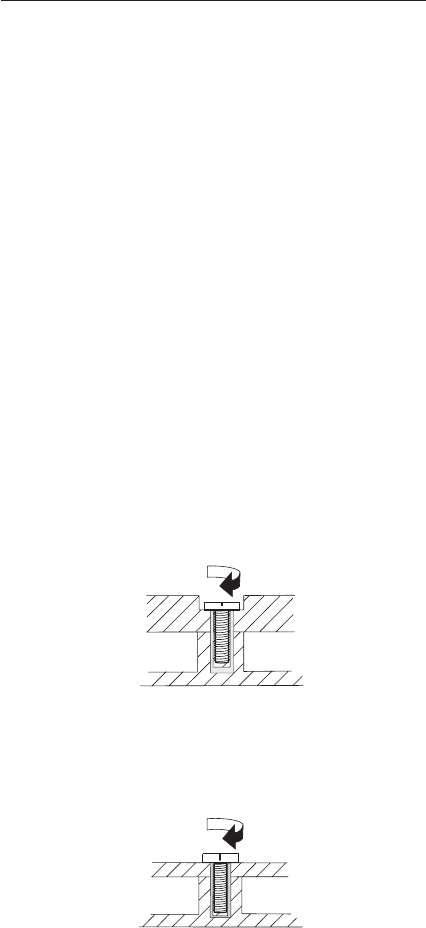
FRU replacement notices
This section contains notices related to removing and
replacing parts. Read this section carefully before replacing
any FRU.
Screw notices
Loose screws can cause a reliability problem. In the
ThinkPad computer, this problem is addressed with special
nylon-coated screws that have the following characteristics:
v They maintain tight connections.
v They do not easily come loose, even with shock or
vibration.
v They are harder to tighten.
v Each one should be used only once.
Do the following when you service this machine:
v Keep the screw kit (for the P/N, see “Miscellaneous
parts” on page 243) in your tool bag.
v Always use new screws.
v Use a torque screwdriver if you have one.
Tighten screws as follows:
v Plastic to plastic
Turn an additional 90 degrees after the screw head
touches the surface of the plastic part:
90 degrees more
(Cross-section)
v Logic card to plastic
Turn an additional 180 degrees after the screw head
touches the surface of the logic card:
180 degrees more
(Cross-section)
v Torque driver
If you have a torque driver, refer to the “Torque” column
for each step.
FRU replacement notices
66 T40/T40p, T41/T41p, T42/T42p
v Make sure that you use the correct screw. If you have a
torque screwdriver, tighten all screws firmly to the torque
shown in the table. Never use a screw that you
removed. Use a new one. Make sure that all of the
screws are tightened firmly.
Retaining serial numbers
This section includes the following descriptions:
v “Restoring the serial number of the system unit”
v “Retaining the UUID” on page 68
v “Reading or writing the ECA information” on page 68
Restoring the serial number of the system
unit
When the computer was manufactured, the EEPROM on
the system board was loaded with the serial numbers of
the system and all major components. These numbers
need to remain the same throughout the life of the
computer.
If you replace the system board, you must restore the
serial number of the system unit to its original value.
Before replacing the system board, save the original serial
number by doing the following:
1. Install the ThinkPad Hardware Maintenance Diskette
Version 1.73 or later, and restart the computer.
2. From the main menu, select 1. Set System
Identification.
3. Select 2. Read S/N data from EEPROM.
The serial number of each device in your computer is
displayed; the serial number of the system unit is listed as
follows:
v 20: Serial number
Write down that number.
Note: The serial number of the system unit is also written
on the label attached to the bottom of the computer.
After you have replaced the system board, restore the
serial number by doing the following:
1. Install the ThinkPad Hardware Maintenance Diskette
Version 1.73 or later and restart the computer.
2. From the main menu, select 1. Set System
Identification.
3. Select 1. Add S/N data from EEPROM.
Follow the instructions on the screen.
FRU replacement notices
ThinkPad T40/T40p, T41/T41p, T42/T42p Series 67
Retaining the UUID
The Universally Unique Identifier (UUID) is a 128-bit
number uniquely assigned to your computer at production
and stored in the EEPROM of your system board. The
algorithm that generates the number is designed to provide
unique IDs until the year A.D. 3400. No two computers in
the world have the same number.
When you replace the system board, you must set the
UUID on the new system board as follows:
1. Install the ThinkPad Hardware Maintenance Diskette
Version 1.73 or later, and restart the computer.
2. From the main menu, select 4. Assign UUID.
A new UUID is created and written. If a valid UUID
already exists, it is not overwritten.
Reading or writing the ECA information
Information on Engineering Change Announcements (ECA)
are stored in the EEPROM of the system board. The
electronic storage of this information simplifies the
procedure to check if the ECA has been previously applied
to a machine. The machine does not need to be
disassembled to check for the ECA application.
To check what ECAs have been previously applied to the
machine, use the ECA Information Read/Write function on
the ThinkPad Hardware Maintenance Diskette Version 1.73
or later.
1. Insert the ThinkPad Hardware Maintenance Diskette
Version 1.73 or later, and restart the computer.
2. From the main menu, select 6. Set ECA Information.
3. To read ECA information, select 2. Read ECA/rework
number from EEPROM and follow the instruction.
4. To read box build date, select 5. Read box build date
from EEPROM, and follow the instruction on the
screen.
After an ECA has been applied to the machine, the
EEPROM must be updated to reflect the ECA's
application. Use the ThinkPad Hardware Maintenance
Diskette Version 1.73 or later to update the EEPROM.
Note: Only the ECA number is stored in the EEPROM.
The machine type of the ECA is assumed be the
same as the machine type of the machine that had
the ECA applied to it.
1. Insert the ThinkPad Hardware Maintenance Diskette
Version 1.73 or later, and restart the computer.
2. From the main menu, select 6. Set ECA Information.
FRU replacement notices
68 T40/T40p, T41/T41p, T42/T42p
3. To write ECA information, select 1. Write ECA/rework
number from EEPROM, and follow the instruction.
4. To write box build date, select 4. Write box build date
from EEPROM, and follow the instruction on the
screen.
If the system board is being replaced, try to read the ECA
information from the old system board and transfer the
information to the new system. If the system board is
inoperable, this will not be possible.
FRU replacement notices
ThinkPad T40/T40p, T41/T41p, T42/T42p Series 69

Removing and replacing a FRU
This section presents directions and drawings for use in
removing and replacing a FRU. Be sure to observe the
following general rules:
1. Do not try to service any computer unless you have
been trained and certified. An untrained person runs
the risk of damaging parts.
2. Before replacing any FRU, review “FRU replacement
notices” on page 66.
3. Begin by removing any FRUs that have to be removed
before the failing FRU. Any such FRUs are listed at the
top of the page. Remove them in the order in which
they are listed.
4. Follow the correct sequence in the steps for removing
the FRU, as given in the drawings by the numbers in
square callouts.
5. When turning a screw to replace a FRU, turn it in the
direction as given by the arrow in the drawing.
6. When removing the FRU, move it in the direction as
given by the arrow in the drawing.
7. To put the new FRU in place, reverse the removal
procedure and follow any notes that pertain to
replacement. For information about connecting and
arranging internal cables, see “Locations” on page 186.
8. When replacing a FRU, use the correct screw as
shown in the procedures.
DANGER
Attention: After replacing a FRU, do not turn on the
computer until you have made sure that all screws,
springs, and other small parts are in place and none are
loose inside the computer. Verify this by shaking the
computer gently and listening for rattling sounds. Metallic
parts or metal flakes can cause electrical short circuits.
Attention: The system board is sensitive to, and can be
damaged by, electrostatic discharge. Before touching it,
establish personal grounding by touching a ground point
with one hand or by using an electrostatic discharge (ESD)
strap (P/N 6405959).
Before removing any FRU, turn off the computer,
unplug all power cords from electrical outlets,
remove the battery pack, and then disconnect any
interconnecting cables.
Removing and replacing a FRU
70 T40/T40p, T41/T41p, T42/T42p
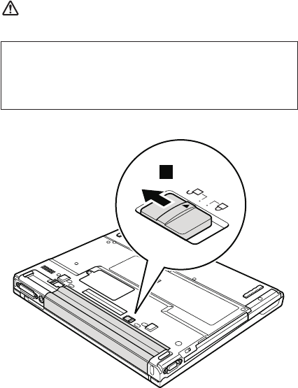
1010 Battery pack for 14.1-in. LCD
models
DANGER
1
(continued)
Use only the battery specified in the parts list for
your computer. Any other battery could ignite or
explode.
Removing and replacing a FRU
ThinkPad T40/T40p, T41/T41p, T42/T42p Series 71
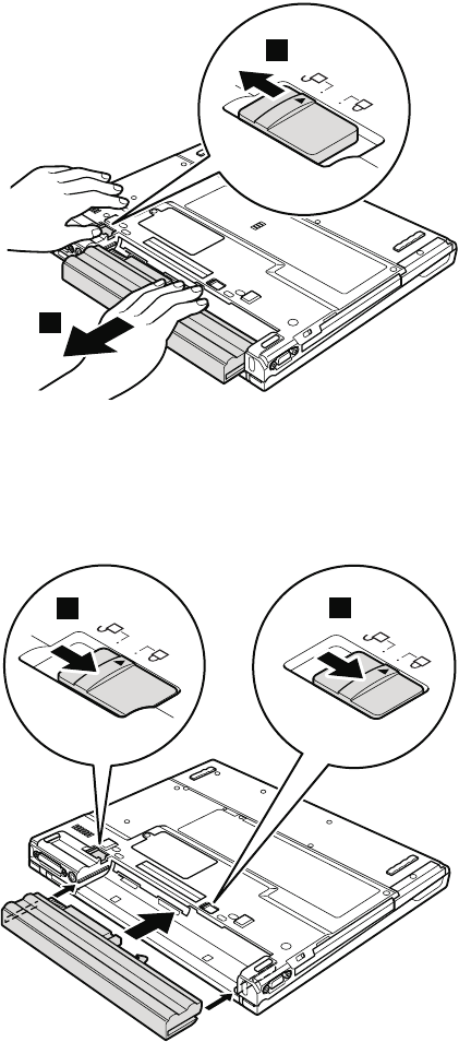
Holding the battery release lever in the unlocked position
2, remove the battery pack 3.
2
3
When installing: Install the battery pack along the slide
rails on the left and right sides of the
battery-pack slot. Then make sure that
both battery latches, a and b, are
locked, as in the following figure.
a
b
Removing and replacing a FRU
72 T40/T40p, T41/T41p, T42/T42p
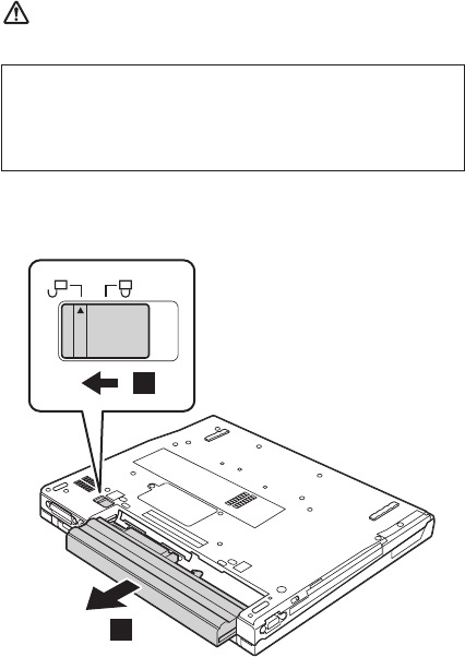
1020 Battery pack for 15.0-in. LCD
models
DANGER
Holding the battery release lever in the unlocked position
1, remove the battery pack 2.
2
1
Use only the battery specified in the parts list for
your computer. Any other battery could ignite or
explode.
Removing and replacing a FRU
ThinkPad T40/T40p, T41/T41p, T42/T42p Series 73
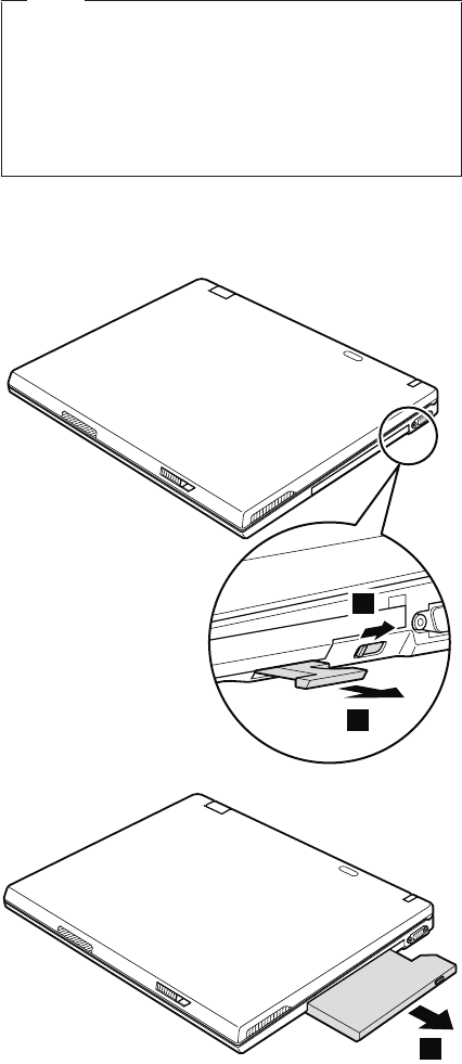
1030 Ultrabay Slim device
Note
Ultrabay Slim does not accept any of the following
devices:
v Ultrabay Plus devices
v Ultrabay 2000 devices
For devices compatible with the Ultrabay Slim bay,
see “Optional FRUs” on page 247.
Note: When you release the switch in step 1, the lever
pops out. In step 2, pull the lever a little to
release the device from the bay.
2
1
3
Removing and replacing a FRU
74 T40/T40p, T41/T41p, T42/T42p
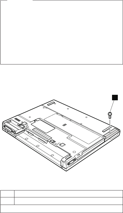
1040 Hard disk drive
Attention
v Do not drop the hard disk drive or apply any
physical shock to it. The hard disk drive is
sensitive to physical shock. Improper handling
can cause damage and permanent loss of data.
v Before removing the drive, have the user make a
backup copy of all the information on it if
possible.
v Never remove the drive while the system is
operating or is in suspend mode.
For access, remove this FRU:
v “1010 Battery pack for 14.1-in. LCD models” on page 71
v “1020 Battery pack for 15.0-in. LCD models” on page 73
1
Note: The hard disk is attached to the cover.
Step Screw (quantity)
1 HDD screw (1) or security screw (1)
Note: Use a 2.5-mm Allen wrench to remove the security screw.
(continued)
Removing and replacing a FRU
ThinkPad T40/T40p, T41/T41p, T42/T42p Series 75
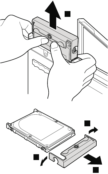
2
3
3
4
When installing: Make sure that the hard-disk connector
is attached firmly.
Removing and replacing a FRU
76 T40/T40p, T41/T41p, T42/T42p
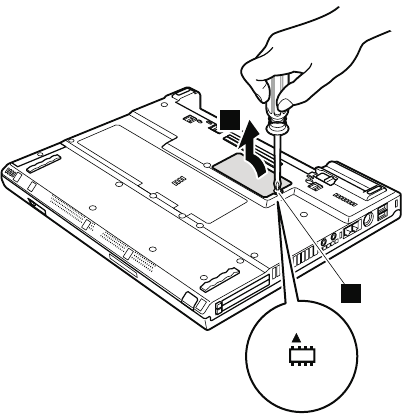
1050 DIMM (optional)
For access, remove this FRU:
v “1010 Battery pack for 14.1-in. LCD models” on page 71
v “1020 Battery pack for 15.0-in. LCD models” on page 73
Note: Loosen the screw 1, but do not remove it.
2
1
(continued)
Removing and replacing a FRU
ThinkPad T40/T40p, T41/T41p, T42/T42p Series 77
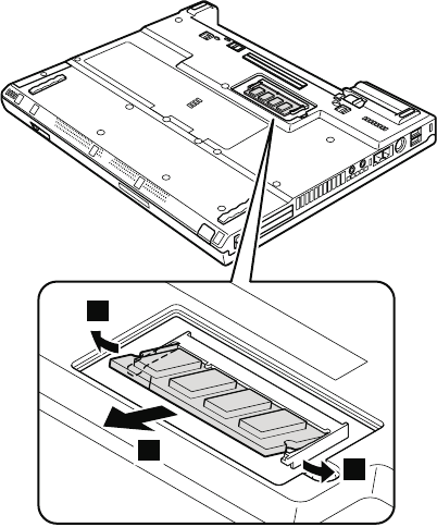
4
3
3
When installing: Insert the notched end of the DIMM into
the socket. Press the DIMM firmly, and
pivot it until it snaps into the place.
Make sure that it is firmly fixed in the
slot and does not move easily.
Removing and replacing a FRU
78 T40/T40p, T41/T41p, T42/T42p
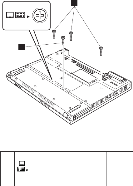
1060 Keyboard
For access, remove this FRU:
v “1010 Battery pack for 14.1-in. LCD models” on page 71
v “1020 Battery pack for 15.0-in. LCD models” on page 73
1
3
1a
Note: Screw 1a is only for the models with 14.1-in. LCD.
Other models do not have this screw.
Step Icon Screw (quantity) Color Torque
1 3
M2 × 10 mm, flat-head,
nylon-coated (3)
Black 0.245 Nm
(2.5 kgfcm)
1a M2 × 10 mm, flat-head,
nylon-coated (1)
Black 0.245 Nm
(2.5 kgfcm)
(continued)
Removing and replacing a FRU
ThinkPad T40/T40p, T41/T41p, T42/T42p Series 79
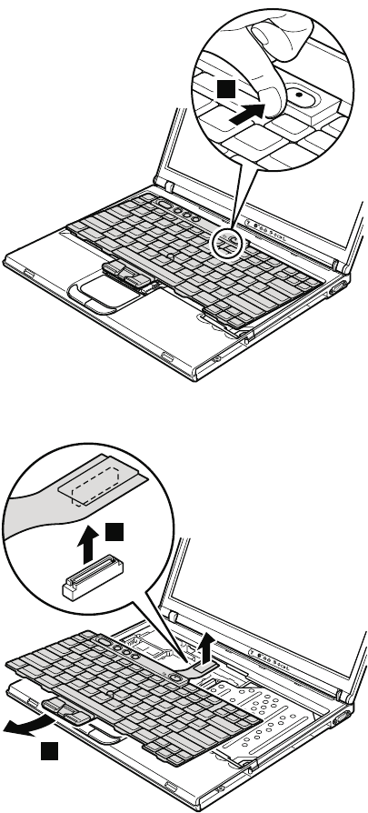
Press the part indicated by the arrow 2 in the direction of
the arrow. This releases the latches of the keyboard from
the frame, so that the front side of the keyboard pops out.
2
Pull the keyboard a little in the direction of the arrow 3,
and then detach the connector 4.
3
4
Removing and replacing a FRU
80 T40/T40p, T41/T41p, T42/T42p
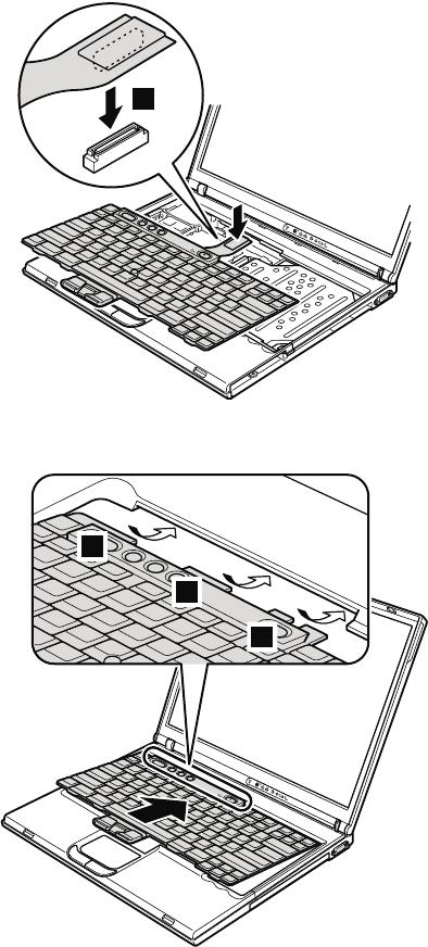
When installing:
1. Attach the connector 1.
1
2. Make sure that the keyboard edges, marked a in the
figure, are under the frame.
a
a
a
(continued)
Removing and replacing a FRU
ThinkPad T40/T40p, T41/T41p, T42/T42p Series 81
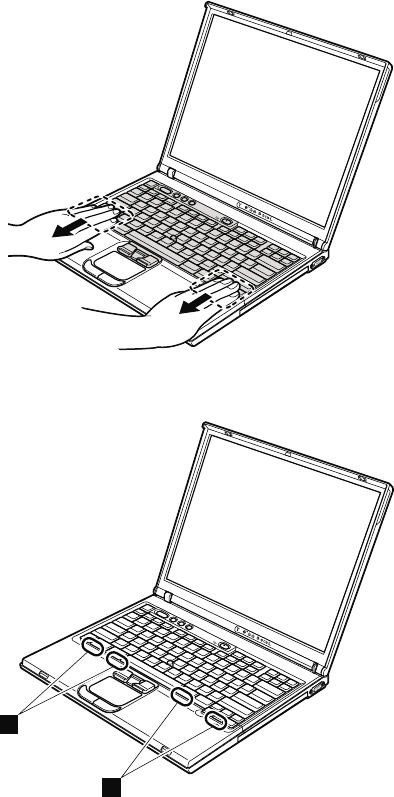
3. To make sure that the front side of the keyboard is
housed firmly, gently press the keys with your fingers
and try to slide the keyboard towards you.
4. Make sure that all the projections on the front side of
the keyboard b are firmly attached under the frame.
b
b
5. Secure the keyboard from the underside of the
computer, using the new screws provided with the
keyboard.
Removing and replacing a FRU
82 T40/T40p, T41/T41p, T42/T42p
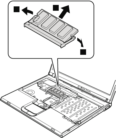
1070 DIMM (standard)
For access, remove these FRUs in order:
v “1010 Battery pack for 14.1-in. LCD models” on page 71
v “1020 Battery pack for 15.0-in. LCD models” on page 73
v “1060 Keyboard” on page 79
1
1
2
When installing: Insert the notched end of the DIMM into
the socket. Press the DIMM firmly, and
pivot it until it snaps into the place.
Make sure that it is firmly fixed in the
slot and does not move easily.
Removing and replacing a FRU
ThinkPad T40/T40p, T41/T41p, T42/T42p Series 83
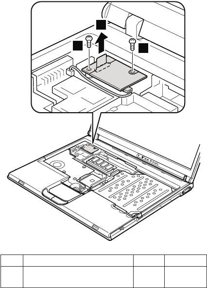
1080 Modem daughter card
(MDC/MDC-2)
For access, remove these FRUs in order:
v “1010 Battery pack for 14.1-in. LCD models” on page 71
v “1020 Battery pack for 15.0-in. LCD models” on page 73
v “1060 Keyboard” on page 79
2
11
Step Screw (quantity) Color Torque
1 M2 × 10 mm, flat-head,
nylon-coated (2)
Black 0.245 Nm
(2.5 kgfcm)
In step 2, remove the card by pulling the tab with your
fingers in the direction of the arrow.
(continued)
Removing and replacing a FRU
84 T40/T40p, T41/T41p, T42/T42p
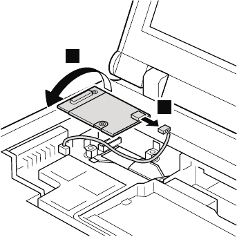
Turn the card over 3, and detach the modem connector
4.
3
4
When installing: Make sure that connector 4 and the
connector on the underside of the card
are firmly attached.
Removing and replacing a FRU
ThinkPad T40/T40p, T41/T41p, T42/T42p Series 85

1090 Bluetooth/Modem daughter card
(BMDC/BMDC-2)
For access, remove these FRUs in order:
v “1010 Battery pack for 14.1-in. LCD models” on page 71
v “1020 Battery pack for 15.0-in. LCD models” on page 73
v “1060 Keyboard” on page 79
2
11
Step Screw (quantity) Color Torque
1 M2 × 10 mm, flat-head,
nylon-coated (2)
Black 0.245 Nm
(2.5 kgfcm)
In step 2, remove the card by pulling the tab with your
fingers in the direction of the arrow.
(continued)
Removing and replacing a FRU
86 T40/T40p, T41/T41p, T42/T42p
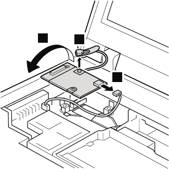
Turn the card over 3, and detach the modem connector
4. If the Bluetooth wireless antenna jack has a tab
marked ″BT″, unplug the jack by pulling the tab with your
fingers. If the antenna jack does not have the tab, unplug
the jack by using the removal tool antenna RF connector
(P/N: 08K7159) or pick the connetor with your fingers and
gently unplug it in direction of the arrow 5.
3
4
5
When installing: Make sure that connector 4, the jack
5, and the connector on the underside
of the card are firmly attached.
Removing and replacing a FRU
ThinkPad T40/T40p, T41/T41p, T42/T42p Series 87

1100 Palm rest or Palm rest with
fingerprint sensor (for 14.1-in. LCD
models)
For access, remove these FRUs in order:
v “1010 Battery pack for 14.1-in. LCD models” on page 71
v “1040 Hard disk drive” on page 75
v “1060 Keyboard” on page 79
Notes
v In models with the fingerprint sensor, the sensor
has been attached to the palm rest FRU as the
child part. In case of the fingerprint sensor has
any defects and needs to be replaced, you need
to replace the palm rest by following the
procedures in this section. The procedures are
same both for the palm rest without the fingerprint
sensor and for the palm rest with the fingerprint
sensor.
v In models xxU and xxF, this FRU is secured by
using a tamper resistant torx head screw (TR7).
(continued)
Removing and replacing a FRU
88 T40/T40p, T41/T41p, T42/T42p
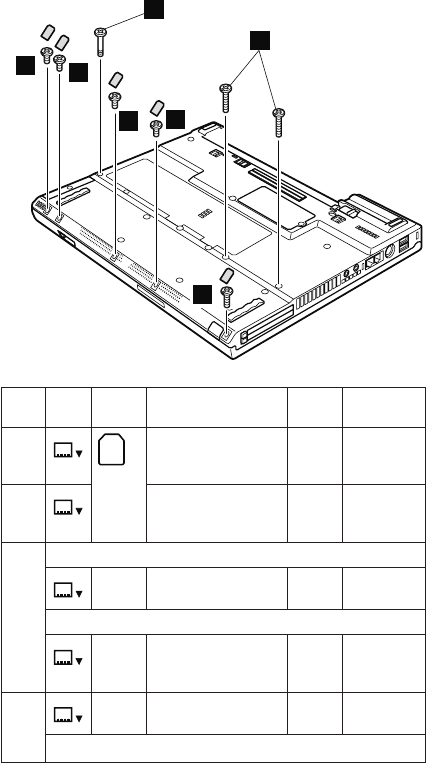
3a
3
11
1
1
2
Step Icon Screw
cap
Screw (quantity) Color Torque
1 1
M2 × 4 mm,
small-head,
nylon-coated (4)
Black 0.245 Nm
(2.5 kgfcm)
2 2
M2 × 5 mm,
bind-head,
nylon-coated (1)
Silver 0.245 Nm
(2.5 kgfcm)
3 Models with a 802.11a/b wireless LAN Mini PCI adapter
4
— M2 × 14 mm, TR7,
nylon-coated (2)
Black 0.204 Nm
(2.0 kgfcm)
Models with other type of Mini PCI adapter
4
— M2 × 14 mm,
bind-head,
nylon-coated (2)
Black 0.204 Nm
(2.0 kgfcm)
3a 4
— Special screw (1) Black 0.204 Nm
(2.0 kgfcm)
Note: Screw 3a is not available in models xxE and xxJ.
(continued)
Removing and replacing a FRU
ThinkPad T40/T40p, T41/T41p, T42/T42p Series 89
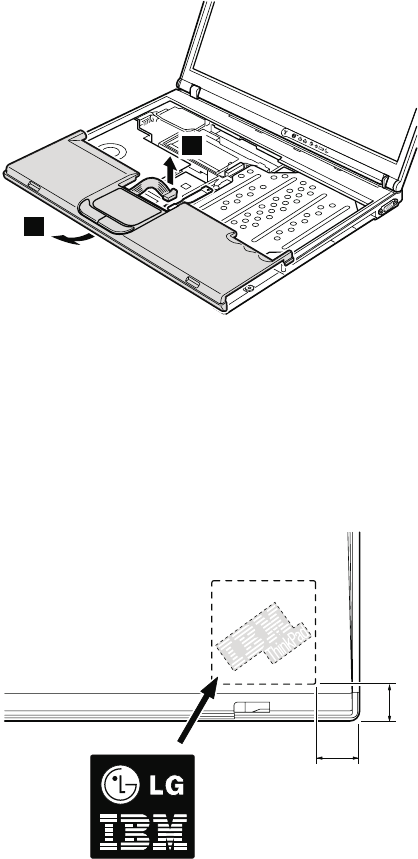
For a model with a touch pad, detach the touch pad
connector by pulling the tab with your fingers in the
direction of arrow 4. Then remove the palm rest in the
direction of arrow 5. For other models, skip step 4.
4
5
When installing: On a model with a touch pad, make
sure that connector 4 is firmly
attached.
Note for LG-IBM models (Korea) in T40/T40p series:
New palm rest FRU is shipped with the LG-IBM logo plate.
When you replace the palm rest, you need to stick the
LG-IBM logo plate as shown in this figure.
15 mm
15 mm
Removing and replacing a FRU
90 T40/T40p, T41/T41p, T42/T42p
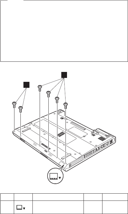
1110 Keyboard bezel or Keyboard bezel
with fingerprint sensor (for 15.0-in. LCD
models)
For access, remove these FRUs in order:
v “1020 Battery pack for 15.0-in. LCD models” on page 73
v “1040 Hard disk drive” on page 75
v “1060 Keyboard” on page 79
Note
In models with the fingerprint sensor, the sensor has
been attached to the keyboard bezel FRU as the
child part. In case of the fingerprint sensor has any
defects and needs to be replaced, you need to
replace the keyboard bezel by following the
procedures in this section. The procedures are
same both for the keyboard bezel without the
fingerprint sensor and for the keyboard bezel with
the fingerprint sensor.
1
1
1
Step Icon Screw (quantity) Color Torque
1 1
M2 × 5 mm, flat-head,
nylon-coated (6)
Black 0.245 Nm
(2.5 kgfcm)
(continued)
Removing and replacing a FRU
ThinkPad T40/T40p, T41/T41p, T42/T42p Series 91
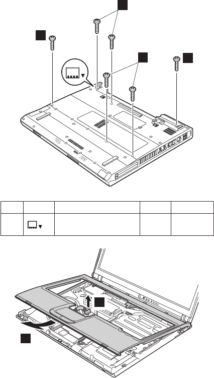
2
2
2
2
2
Step Icon Screw (quantity) Color Torque
2 2
M2 × 14 mm, bind-head,
nylon-coated (6)
Black 0.245 Nm
(2.5 kgfcm)
3
4
Removing and replacing a FRU
92 T40/T40p, T41/T41p, T42/T42p
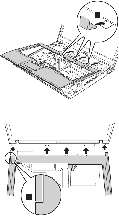
When installing:
1. Place the keyboard bezel so that the three latches are
fixed in place 1.
1
While inserting the three latches, align the top-left
corner of the keyboard bezel as in figure a.
a
(continued)
Removing and replacing a FRU
ThinkPad T40/T40p, T41/T41p, T42/T42p Series 93
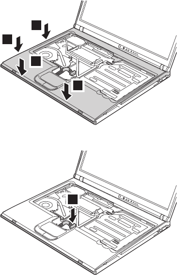
2. Press the left edges 2 and the front edges 3 of the
keyboard bezel until the latches are snapped.
3
3
2
2
3. Attach the touch pad connector 4.
4
(continued)
Removing and replacing a FRU
94 T40/T40p, T41/T41p, T42/T42p
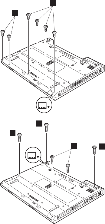
4. Secure the keyboard bezel from the underside of the
computer with the screws b and c.
b
1
b
c
c
c
2
c
5. Attach the keyboard.
(continued)
Removing and replacing a FRU
ThinkPad T40/T40p, T41/T41p, T42/T42p Series 95
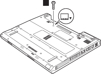
6. Secure the keyboard bezel from the underside of the
computer with the screw d. This screw cannot be
fastened properly without attaching keyboard.
d
2
Removing and replacing a FRU
96 T40/T40p, T41/T41p, T42/T42p
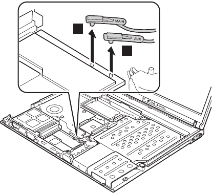
1120 Mini PCI adapter
For access, remove these FRUs in order:
v “1010 Battery pack for 14.1-in. LCD models” on page 71
v “1020 Battery pack for 15.0-in. LCD models” on page 73
v “1040 Hard disk drive” on page 75
v “1060 Keyboard” on page 79
v “1100 Palm rest or Palm rest with fingerprint sensor (for
14.1-in. LCD models)” on page 88
v “1110 Keyboard bezel or Keyboard bezel with fingerprint
sensor (for 15.0-in. LCD models)” on page 91
If the wireless antenna jacks have tabs marked ″MAIN″ or
″AUX″, unplug the jacks by pulling the tabs with your
fingers. If the antenna jacks do not have the tabs, unplug
the jacks by using the removal tool antenna RF connector
(P/N: 08K7159) or pick the connectors with your fingers
and gently unplug it in direction of the arrow 1 and 2.
1
2
(continued)
Removing and replacing a FRU
ThinkPad T40/T40p, T41/T41p, T42/T42p Series 97
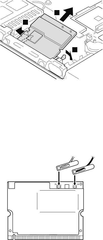
3
3
4
When installing: Plug in the wireless antenna cable as
follows:
Intel PRO/Wireless LAN 2100 3B Mini PCI Adapter or
Intel PRO Wireless 2200BG Mini-PCI Adapter
In case of the antenna jacks have the tabs, plug the gray
antenna cable with the tab marked MAIN into jack M, and
the black antenna cable with the tab marked AUX into jack
A.
In case of the antenna jacks do not have the tabs, plug the
gray cable to jack M, and the black cable to jack A.
MAIN
AUX
Removing and replacing a FRU
98 T40/T40p, T41/T41p, T42/T42p
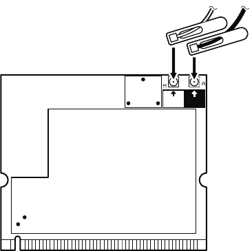
Cisco Aironet Wireless 802.11b
In case of the antenna jacks have the tabs, plug the gray
antenna cable with the tab marked MAIN into jack M, and
the black antenna cable with the tab marked AUX into jack
A.
In case of the antenna jacks do not have the tabs, plug the
gray cable to jack M, and the black cable to jack A.
MAIN
MAIN
AUX
AUX
Removing and replacing a FRU
ThinkPad T40/T40p, T41/T41p, T42/T42p Series 99
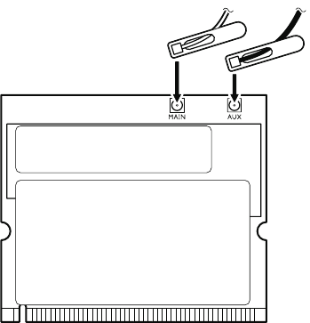
ThinkPad Dual-Band 11a/b Wi-Fi Wireless Mini PCI
Adapter, ThinkPad 11a/b/g Wireless LAN Mini PCI
Adapter, or ThinkPad 11b/g Wireless LAN Mini PCI
Adapter
In case of the antenna jacks have the tabs, plug the gray
antenna cable with the tab marked MAIN into jack MAIN,
and the black antenna cable with the tab marked AUX into
jack AUX.
In case of the antenna jacks do not have the tabs, plug the
gray cable to jack MAIN, and the black cable to jack AUX.
MAIN
AUX
Insert the notched end of the card into the socket, and
then press the card firmly. Pivot the card until it snaps into
place. Make sure that it is firmly fixed in the slot and does
not move easily.
Removing and replacing a FRU
100 T40/T40p, T41/T41p, T42/T42p
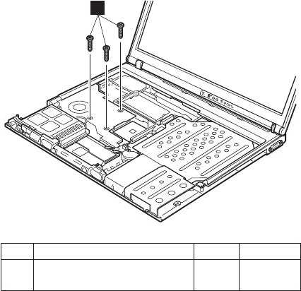
1130 Fan assembly
For access, remove these FRUs in order:
v “1010 Battery pack for 14.1-in. LCD models” on page 71
v “1020 Battery pack for 15.0-in. LCD models” on page 73
v “1040 Hard disk drive” on page 75
v “1060 Keyboard” on page 79
v “1100 Palm rest or Palm rest with fingerprint sensor (for
14.1-in. LCD models)” on page 88
v “1110 Keyboard bezel or Keyboard bezel with fingerprint
sensor (for 15.0-in. LCD models)” on page 91
1
Step Screw (quantity) Color Torque
1 M2 × 10 mm, flat-head,
nylon-coated (3)
Black 0.245 Nm
(2.5 kgfcm)
(continued)
Removing and replacing a FRU
ThinkPad T40/T40p, T41/T41p, T42/T42p Series 101
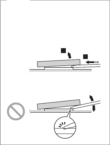
Important
In step 2, insert the tip of the tool horizontally
between the fan assembly and the CPU, as
indicated by arrow a. Then slightly push the tool
into the gap until the fan assembly comes off. Do
not move the tool upward or downward to remove
the fan assembly between the gap. To do so, the
CPU or the other electrical component may be
damaged.
a
2
(continued)
Removing and replacing a FRU
102 T40/T40p, T41/T41p, T42/T42p
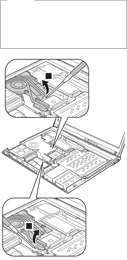
Important
In step 2a and 2b, be careful not to damage the
copper plate of the fan assembly. Step 2a is for
the fan assembly, long and for the fan assembly,
long M10. Step 2b is for the fan assembly, short.
Distortion of the fan assembly may cause a thermal
problem.
2b
2a
(continued)
Removing and replacing a FRU
ThinkPad T40/T40p, T41/T41p, T42/T42p Series 103
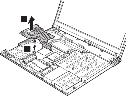
4
3
When installing: Make sure that the connector 4 is
firmly attached.
Removing and replacing a FRU
104 T40/T40p, T41/T41p, T42/T42p
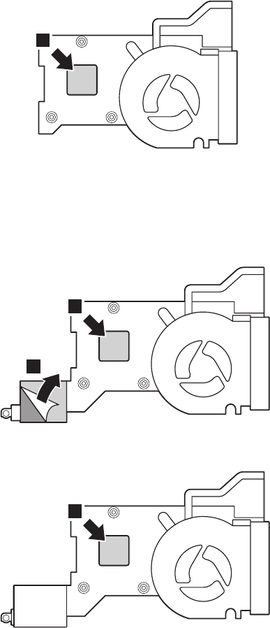
When installing: Apply thermal grease on the part
marked a as in the following figures.
Only in the case of Fan assembly, long, you need to peel
the plastic sheet b off on the thermal rubber before you
place it on the system board. Fan assembly, long M10
DOES NOT have the plastic sheet.
a
Figure 1. Fan assembly, short
a
b
Figure 2. Fan assembly, long
a
Figure 3. Fan assembly, long M10
Removing and replacing a FRU
ThinkPad T40/T40p, T41/T41p, T42/T42p Series 105
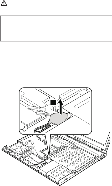
1140 Backup battery for 14.1-in. LCD
models
DANGER
For access, remove these FRUs in order:
v “1010 Battery pack for 14.1-in. LCD models” on page 71
v “1040 Hard disk drive” on page 75
v “1060 Keyboard” on page 79
v “1100 Palm rest or Palm rest with fingerprint sensor (for
14.1-in. LCD models)” on page 88
1
(continued)
Use only the battery specified in the parts list for
your computer. Any other battery could ignite or
explode.
Removing and replacing a FRU
106 T40/T40p, T41/T41p, T42/T42p
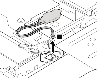
2
When installing: Make sure that the battery connector
2 is firmly attached.
Removing and replacing a FRU
ThinkPad T40/T40p, T41/T41p, T42/T42p Series 107
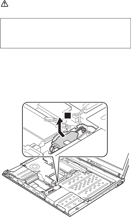
1150 Backup battery for 15.0-in. LCD
models
DANGER
For access, remove these FRUs in order:
v “1020 Battery pack for 15.0-in. LCD models” on page 73
v “1040 Hard disk drive” on page 75
v “1060 Keyboard” on page 79
v “1110 Keyboard bezel or Keyboard bezel with fingerprint
sensor (for 15.0-in. LCD models)” on page 91
1
(continued)
Use only the battery specified in the parts list for
your computer. Any other battery could ignite or
explode.
Removing and replacing a FRU
108 T40/T40p, T41/T41p, T42/T42p
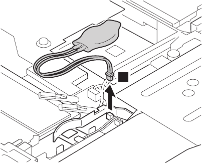
2
When installing: Make sure that the battery connector
2 is firmly attached.
Removing and replacing a FRU
ThinkPad T40/T40p, T41/T41p, T42/T42p Series 109
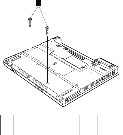
1160 Speaker assembly
For access, remove these FRUs in order:
v “1010 Battery pack for 14.1-in. LCD models” on page 71
v “1020 Battery pack for 15.0-in. LCD models” on page 73
v “1040 Hard disk drive” on page 75
v “1060 Keyboard” on page 79
v “1100 Palm rest or Palm rest with fingerprint sensor (for
14.1-in. LCD models)” on page 88
v “1110 Keyboard bezel or Keyboard bezel with fingerprint
sensor (for 15.0-in. LCD models)” on page 91
1
Step Screw (quantity) Color Torque
1 M2 × 10 mm, flat-head,
nylon-coated (2)
Black 0.245 Nm
(2.5 kgfcm)
(continued)
Removing and replacing a FRU
110 T40/T40p, T41/T41p, T42/T42p
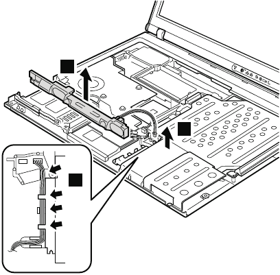
In step 3, release the speaker cables from the cable
guide.
4
2
3
When installing: Make sure that the connector 4 is
firmly attached. Then route the cable as
in 3.
Removing and replacing a FRU
ThinkPad T40/T40p, T41/T41p, T42/T42p Series 111
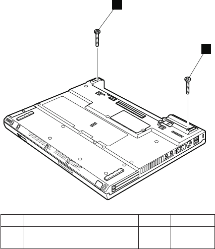
1170 Keyboard bezel for 14.1-in. LCD
models
For access, remove these FRUs in order:
v “1010 Battery pack for 14.1-in. LCD models” on page 71
v “1040 Hard disk drive” on page 75
v “1060 Keyboard” on page 79
v “1100 Palm rest or Palm rest with fingerprint sensor (for
14.1-in. LCD models)” on page 88
1
1
Step Screw (quantity) Color Torque
1 M2 × 19 mm, bind-head,
nylon-coated (2)
Black 0.245 Nm
(2.5 kgfcm)
(continued)
Removing and replacing a FRU
112 T40/T40p, T41/T41p, T42/T42p
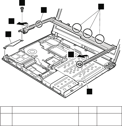
3
2
3
a
a
b
a
Step Screw (quantity) Color Torque
2 M2 × 4 mm, bind-head,
nylon-coated (1)
Black 0.245 Nm
(2.5 kgfcm)
In step 3, make sure that all the latches marked a are
detached, and then remove the bezel.
When installing: Make sure that all the latches marked
a are firmly attached. Attach harness
left (b), and then secure the keyboard
bezel with the screws.
Removing and replacing a FRU
ThinkPad T40/T40p, T41/T41p, T42/T42p Series 113
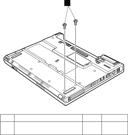
1180 PC Card slot assembly for 14.1-in.
LCD models
For access, remove these FRUs in order:
v “1010 Battery pack for 14.1-in. LCD models” on page 71
v “1040 Hard disk drive” on page 75
v “1060 Keyboard” on page 79
v “1100 Palm rest or Palm rest with fingerprint sensor (for
14.1-in. LCD models)” on page 88
v “1160 Speaker assembly” on page 110
v “1170 Keyboard bezel for 14.1-in. LCD models” on page
112
1
Step Screw (quantity) Color Torque
1 M2 × 4 mm, bind-head,
nylon-coated (2)
Black 0.204 Nm
(2.0 kgfcm)
(continued)
Removing and replacing a FRU
114 T40/T40p, T41/T41p, T42/T42p
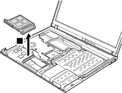
2
When installing: Make sure that the connector on the
underside of the PC card slot 2 is
firmly attached, and then secure the slot
with the screws.
Removing and replacing a FRU
ThinkPad T40/T40p, T41/T41p, T42/T42p Series 115
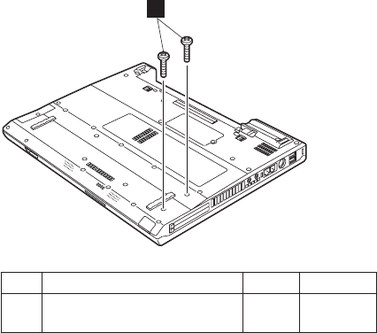
1190 PC Card slot assembly for 15.0-in.
LCD models
For access, remove these FRUs in order:
v “1020 Battery pack for 15.0-in. LCD models” on page 73
v “1040 Hard disk drive” on page 75
v “1060 Keyboard” on page 79
v “1110 Keyboard bezel or Keyboard bezel with fingerprint
sensor (for 15.0-in. LCD models)” on page 91
v “1160 Speaker assembly” on page 110
1
Step Screw (quantity) Color Torque
1 M2 × 5 mm, flat-head,
nylon-coated (2)
Black 0.204 Nm
(2.0 kgfcm)
(continued)
Removing and replacing a FRU
116 T40/T40p, T41/T41p, T42/T42p
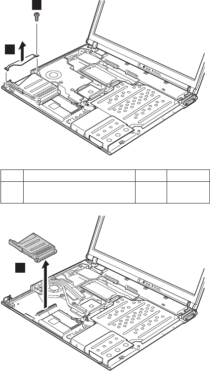
2
3
Step Screw (quantity) Color Torque
2 M2 × 4 mm, bind-head,
nylon-coated (1)
Black 0.245 Nm
(2.5 kgfcm)
4
When installing: Make sure that the connector on the
underside of the PC card slot 2 is
firmly attached, and then secure the slot
with the screws.
Removing and replacing a FRU
ThinkPad T40/T40p, T41/T41p, T42/T42p Series 117
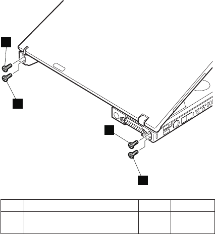
1200 LCD assembly for 14.1-in. LCD
models
For access, remove these FRUs in order:
v “1010 Battery pack for 14.1-in. LCD models” on page 71
v “1040 Hard disk drive” on page 75
v “1060 Keyboard” on page 79
v “1090 Bluetooth/Modem daughter card
(BMDC/BMDC-2)” on page 86
v “1100 Palm rest or Palm rest with fingerprint sensor (for
14.1-in. LCD models)” on page 88
v “1120 Mini PCI adapter” on page 97
v “1170 Keyboard bezel for 14.1-in. LCD models” on page
112
1
1
1
1
Step Screw (quantity) Color Torque
1 M2.5 × 4.8 mm, bind-head,
nylon-coated (4)
Black 0.392 Nm
(4 kgfcm)
(continued)
Removing and replacing a FRU
118 T40/T40p, T41/T41p, T42/T42p
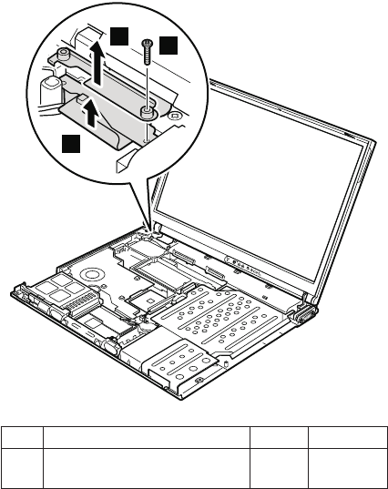
3
4
2
Step Screw (quantity) Color Torque
2 M2 × 14 mm, bind-head,
nylon-coated (1)
Black 0.245 Nm
(2.5 kgfcm)
After removing the screw, remove bracket 3. Then
detach the LCD connector 4.
When installing: Make sure that the bracket 3 and the
connector 4 are firmly attached, and
then secure them with the screw.
(continued)
Removing and replacing a FRU
ThinkPad T40/T40p, T41/T41p, T42/T42p Series 119
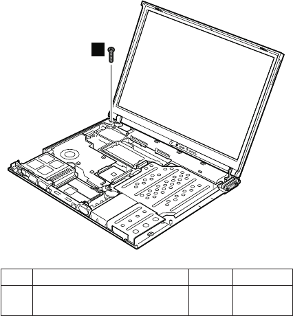
5
Step Screw (quantity) Color Torque
5 M2 × 10 mm, flat-head,
nylon-coated (1)
Black 0.245 Nm
(2.5 kgfcm)
(continued)
Removing and replacing a FRU
120 T40/T40p, T41/T41p, T42/T42p
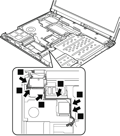
Release the antenna cables from the cable guide 6.
6
6
6
6
6
6
When installing: Make sure that the antenna cables are
correctly routed and securely in place.
(continued)
Removing and replacing a FRU
ThinkPad T40/T40p, T41/T41p, T42/T42p Series 121
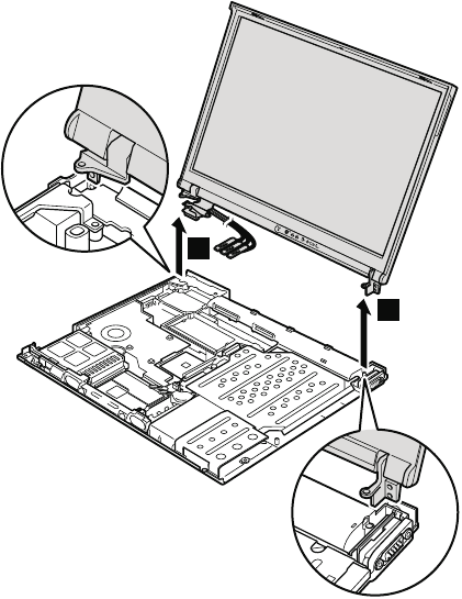
7
7
When installing: Make sure that the security keyhole
which is on the left-rear corner of the
base cover and the keyhole of the
bracket inside are aligning firmly.
Removing and replacing a FRU
122 T40/T40p, T41/T41p, T42/T42p
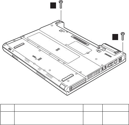
1210 LCD assembly for 15.0-in. LCD
models
For access, remove these FRUs in order:
v “1020 Battery pack for 15.0-in. LCD models” on page 73
v “1040 Hard disk drive” on page 75
v “1060 Keyboard” on page 79
v “1090 Bluetooth/Modem daughter card
(BMDC/BMDC-2)” on page 86
v “1110 Keyboard bezel or Keyboard bezel with fingerprint
sensor (for 15.0-in. LCD models)” on page 91
v “1120 Mini PCI adapter” on page 97
1
1
Step Screw (quantity) Color Torque
1 M2 × 10 mm, flat-head,
nylon-coated (2)
Black 0.245 Nm
(2.5 kgfcm)
(continued)
Removing and replacing a FRU
ThinkPad T40/T40p, T41/T41p, T42/T42p Series 123
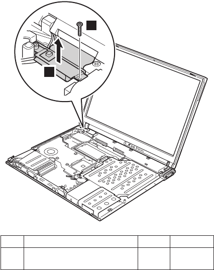
2
3
Step Screw (quantity) Color Torque
2 M2 × 12 mm, flat-head,
nylon-coated (1)
Black 0.245 Nm
(2.5 kgfcm)
When installing: Make sure that the connector 3 is
firmly attached, and then secure it with
the screw.
(continued)
Removing and replacing a FRU
124 T40/T40p, T41/T41p, T42/T42p
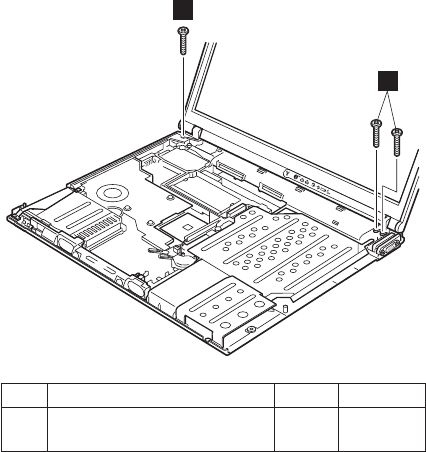
4
4
Step Screw (quantity) Color Torque
4 M2 × 10 mm, flat-head,
nylon-coated (3)
Black 0.245 Nm
(2.5 kgfcm)
(continued)
Removing and replacing a FRU
ThinkPad T40/T40p, T41/T41p, T42/T42p Series 125
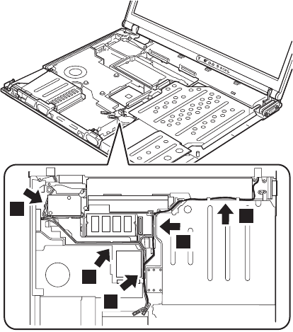
Release the antenna cables from the cable guide 5.
5
5
5
5
5
When installing: Make sure that the antenna cables are
correctly routed and securely in place.
(continued)
Removing and replacing a FRU
126 T40/T40p, T41/T41p, T42/T42p
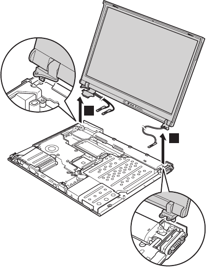
6
6
When installing: Make sure that the security keyhole
which is on the left-rear corner of the
base cover and the keyhole of the
bracket inside are aligning firmly.
Removing and replacing a FRU
ThinkPad T40/T40p, T41/T41p, T42/T42p Series 127
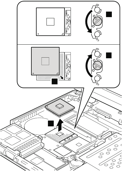
1220 CPU
For access, remove these FRUs in order:
v “1010 Battery pack for 14.1-in. LCD models” on page 71
v “1040 Hard disk drive” on page 75
v “1060 Keyboard” on page 79
v “1100 Palm rest or Palm rest with fingerprint sensor (for
14.1-in. LCD models)” on page 88
v “1110 Keyboard bezel or Keyboard bezel with fingerprint
sensor (for 15.0-in. LCD models)” on page 91
v “1170 Keyboard bezel for 14.1-in. LCD models” on page
112
v “1200 LCD assembly for 14.1-in. LCD models” on page
118
v “1130 Fan assembly” on page 101
Rotate the head of the screw in the direction shown by
arrow 1 to release the lock; then remove the CPU 2.
2
1
b
a
When installing: Place the CPU on the CPU socket a,
and then rotate the head of the screw in
the direction shown by arrow b to
secure the CPU.
Removing and replacing a FRU
128 T40/T40p, T41/T41p, T42/T42p
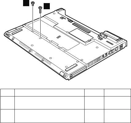
1230 Ultrabay Slim guide rail assembly
for 14.1-in. LCD models
For access, remove these FRUs in order:
v “1010 Battery pack for 14.1-in. LCD models” on page 71
v “1040 Hard disk drive” on page 75
v “1060 Keyboard” on page 79
v “1100 Palm rest or Palm rest with fingerprint sensor (for
14.1-in. LCD models)” on page 88
v “1160 Speaker assembly” on page 110
v “1170 Keyboard bezel for 14.1-in. LCD models” on page
112
v “1180 PC Card slot assembly for 14.1-in. LCD models”
on page 114
v “1200 LCD assembly for 14.1-in. LCD models” on page
118
1
2
Step Screw (quantity) Color Torque
1 M2 × 14 mm, bind-head,
nylon-coated (1)
Black 0.204 Nm
(2.0 kgfcm)
2 M2 × 4 mm, bind-head,
nylon-coated (1)
Black 0.204 Nm
(2.0 kgfcm)
(continued)
Removing and replacing a FRU
ThinkPad T40/T40p, T41/T41p, T42/T42p Series 129
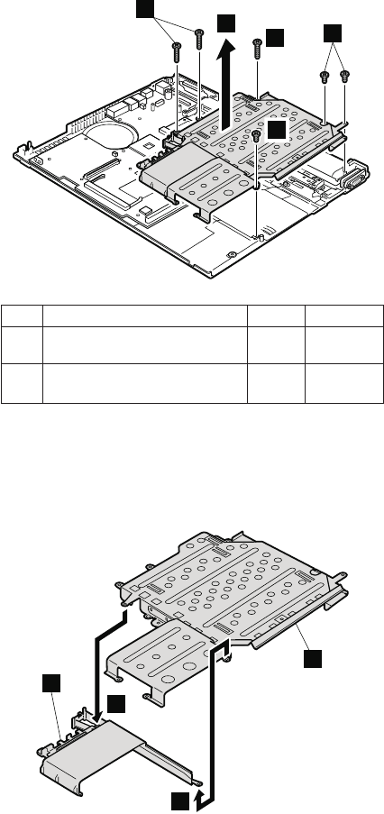
4
54
3
3
Step Screw (quantity) Color Torque
3 M2 × 10 mm, flat-head,
nylon-coated (3)
Black 0.245 Nm
(2.5 kgfcm)
4 M2 × 3 mm, small-head,
nylon-coated (3)
Silver 0.245 Nm
(2.5 kgfcm)
In step 5, remove the Ultrabay Slim guide rail assembly
and the hard disk drive guide rail together.
Separate the Ultrabay Slim guide rail assembly a and
the hard disk drive guide rail b.
6
6
a
b
Removing and replacing a FRU
130 T40/T40p, T41/T41p, T42/T42p
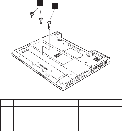
1240 Ultrabay Slim guide rail assembly
for 15.0-in. LCD models
For access, remove these FRUs in order:
v “1020 Battery pack for 15.0-in. LCD models” on page 73
v “1040 Hard disk drive” on page 75
v “1060 Keyboard” on page 79
v “1110 Keyboard bezel or Keyboard bezel with fingerprint
sensor (for 15.0-in. LCD models)” on page 91
v “1160 Speaker assembly” on page 110
2
1
Step Screw (quantity) Color Torque
1 M2 × 5 mm, flat-head,
nylon-coated (2)
Black 0.204 Nm
(2.0 kgfcm)
2 M2 × 14 mm, bind-head,
nylon-coated (1)
Black 0.204 Nm
(2.0 kgfcm)
(continued)
Removing and replacing a FRU
ThinkPad T40/T40p, T41/T41p, T42/T42p Series 131
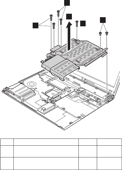
54
3
3
3
Step Screw (quantity) Color Torque
3 M2 × 10 mm, flat-head,
nylon-coated (5)
Black 0.245 Nm
(2.5 kgfcm)
4 M2 × 4 mm, bind-head,
nylon-coated (2)
Black 0.245 Nm
(2.5 kgfcm)
In step 5, remove the Ultrabay Slim guide rail assembly
and the hard disk drive guide rail together.
(continued)
Removing and replacing a FRU
132 T40/T40p, T41/T41p, T42/T42p
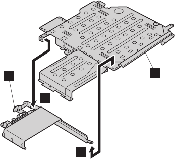
Separate the Ultrabay Slim guide rail assembly a and
the hard disk drive guide rail b.
6
6
a
b
Removing and replacing a FRU
ThinkPad T40/T40p, T41/T41p, T42/T42p Series 133
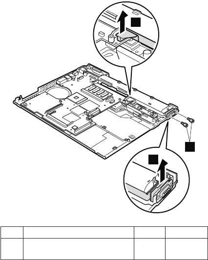
1250 VGA and Ultrabay Slim device
eject button cable
For access, remove these FRUs in order:
v “1010 Battery pack for 14.1-in. LCD models” on page 71
v “1020 Battery pack for 15.0-in. LCD models” on page 73
v “1040 Hard disk drive” on page 75
v “1060 Keyboard” on page 79
v “1100 Palm rest or Palm rest with fingerprint sensor (for
14.1-in. LCD models)” on page 88
v “1110 Keyboard bezel or Keyboard bezel with fingerprint
sensor (for 15.0-in. LCD models)” on page 91
v “1170 Keyboard bezel for 14.1-in. LCD models” on page
112
v “1200 LCD assembly for 14.1-in. LCD models” on page
118
v “1210 LCD assembly for 15.0-in. LCD models” on page
123
v “1230 Ultrabay Slim guide rail assembly for 14.1-in. LCD
models” on page 129
v “1240 Ultrabay Slim guide rail assembly for 15.0-in. LCD
models” on page 131
1
3
2
Step Screw (quantity) Color Torque
2 Hex stud (2) Silver 0.392 Nm
(4 kgfcm)
(continued)
Removing and replacing a FRU
134 T40/T40p, T41/T41p, T42/T42p
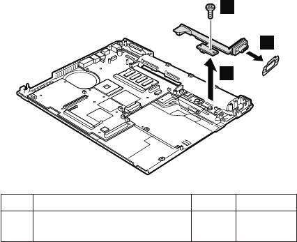
5
4
6
Step Screw (quantity) Color Torque
4 M2 × 4 mm, bind-head,
nylon-coated (1)
Black 0.245 Nm
(2.5 kgfcm)
When installing: Make sure that the connector 1 is
firmly attached.
Removing and replacing a FRU
ThinkPad T40/T40p, T41/T41p, T42/T42p Series 135
1260 System board and base cover for
14.1-in. LCD models
For access, remove these FRUs, in order:
v “1010 Battery pack for 14.1-in. LCD models” on page 71
v “1030 Ultrabay Slim device” on page 74
v “1040 Hard disk drive” on page 75
v “1050 DIMM (optional)” on page 77
v “1060 Keyboard” on page 79
v “1070 DIMM (standard)” on page 83
v “1080 Modem daughter card (MDC/MDC-2)” on page 84
v “1090 Bluetooth/Modem daughter card
(BMDC/BMDC-2)” on page 86
v “1100 Palm rest or Palm rest with fingerprint sensor (for
14.1-in. LCD models)” on page 88
v “1120 Mini PCI adapter” on page 97
v “1130 Fan assembly” on page 101
v “1140 Backup battery for 14.1-in. LCD models” on page
106
v “1160 Speaker assembly” on page 110
v “1170 Keyboard bezel for 14.1-in. LCD models” on page
112
v “1180 PC Card slot assembly for 14.1-in. LCD models”
on page 114
v “1200 LCD assembly for 14.1-in. LCD models” on page
118
v “1220 CPU” on page 128
v “1230 Ultrabay Slim guide rail assembly for 14.1-in. LCD
models” on page 129
v “1250 VGA and Ultrabay Slim device eject button cable”
on page 134
Removing and replacing a FRU
136 T40/T40p, T41/T41p, T42/T42p
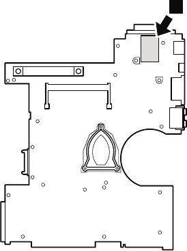
Important notice for handling the system board in
ThinkPad T40 series:
There are two types of system board FRU for the
ThinkPad T40 series, as follows:
v System board with the security chip (bottom view)
Note: The security chip a is embedded on the
underside of the system board.
a
Removing and replacing a FRU
ThinkPad T40/T40p, T41/T41p, T42/T42p Series 137
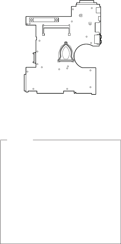
v System board without the security chip (bottom view)
Begin by checking the FRU number of the system board,
and be sure to use the correct system board for the
computer. For the FRU numbers, see “Parts list” on page
190.
Important
If the ThinkPad computer you are servicing has a
security chip, bear the following in mind:
v Do not remove the security chip from the
system board. If the security chip is removed by
accident, reinstall it on the system board
immediately. Make sure that it is firmly fixed on
the system board and does not move easily.
v The security chip cannot be used with any other
system board.
v The system board cannot be used with any other
security chip.
v The system board cannot be used without the
security chip.
v If you return a defective system board, you must
check whether the security chip is embedded. If it
is not, the board may not be covered under
warranty.
Removing and replacing a FRU
138 T40/T40p, T41/T41p, T42/T42p

Important notice for handling the system board in
ThinkPad T41 series:
In ThinkPad T41 series, the security chip a is soldered
on the underside of the system board as in this figure.
a
In ThinkPad T41 series, accelerometer chip for the HDD
Active Protection System b is also soldered on the
topside of the system board.
b
Removing and replacing a FRU
ThinkPad T40/T40p, T41/T41p, T42/T42p Series 139

Important
When handling the system board in ThinkPad T41
series, bear the following in mind.
v The system board of the ThinkPad T41 series
has an accelerometer, which can be broken by
applying several thousands of G-forces.
Note: Dropping a system board from a height of
as little as 6 inches so that it falls flat on a
hard bench can subject the accelerometer
to as much as 6,000 G’s of shock.
v Be careful not to drop the system board on a
bench top that has a hard surface, such as metal,
wood, or composite.
v If a system board is dropped, you must test it,
using PC-Doctor for DOS, to make sure that the
HDD Active Protection still functions (see below).
Note: If the test shows that HDD Active
Protection is not functioning, be sure to
document the drop in any reject report,
and replace the system board.
v Avoid rough handling of any kind.
v At every point in the process, be sure not to drop
or stack the system board.
v If you put a system board down, be sure to put it
only on a padded surface such as an ESD mat or
conductive corrugated material.
After replacing the system board, run PC-Doctor for
DOS to make sure that HDD Active Protection still
functions. The procedure is as follows:
1. Place the computer on a horizontal surface.
2. Run Diagnostics --> Other Devices --> HDD
Active Protection Test.
Attention: Do not apply physical shock to the
computer while the test is running.
Removing and replacing a FRU
140 T40/T40p, T41/T41p, T42/T42p
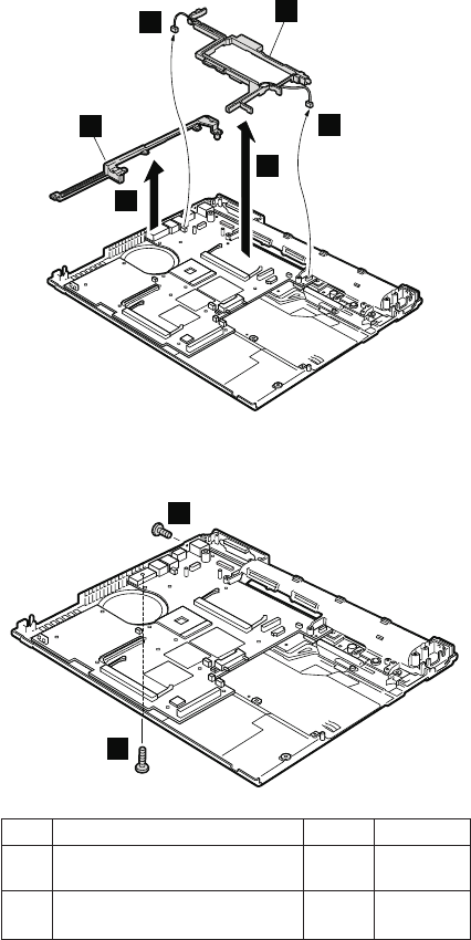
Before removing the system board, remove the support
structure (a) and the cable guide (b).
2
2
1
3
b
a
When installing: Make sure that the connectors 2 are
firmly attached to the system board.
5
4
Step Screw (quantity) Color Torque
4 M2 × 10 mm, flat-head,
nylon-coated (1)
Black 0.245 Nm
(2.5 kgfcm)
5 M2.5 × 4 mm, bind-head,
nylon-coated (1)
Black 0.392 Nm
(4 kgfcm)
(continued)
Removing and replacing a FRU
ThinkPad T40/T40p, T41/T41p, T42/T42p Series 141
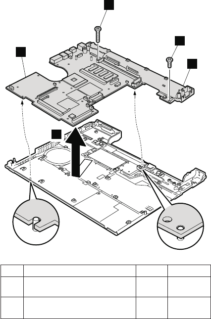
6
7
c
d
8
Step Screw (quantity) Color Torque
6 M2 × 3 mm, small-head,
nylon-coated (1)
Silver 0.245 Nm
(2.5 kgfcm)
7 M2 × 10 mm, flat-head,
nylon-coated (1)
Black 0.245 Nm
(2.5 kgfcm)
In step 8, remove the I/O plate bracket (c) and the
system board (d) together.
(continued)
Removing and replacing a FRU
142 T40/T40p, T41/T41p, T42/T42p
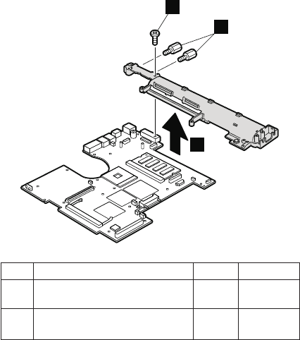
10
9
11
Step Screw (quantity) Color Torque
9 Hex stud (2) Silver 0.392 Nm
(4 kgfcm)
10 M2.5 × 3 mm, bind-head,
nylon-coated (1)
Gold 0.392 Nm
(4 kgfcm)
When installing: Attach the system board so that the two
small projections on the base cover fit
into the holes provided, and then secure
the system board with the screw.
Removing and replacing a FRU
ThinkPad T40/T40p, T41/T41p, T42/T42p Series 143
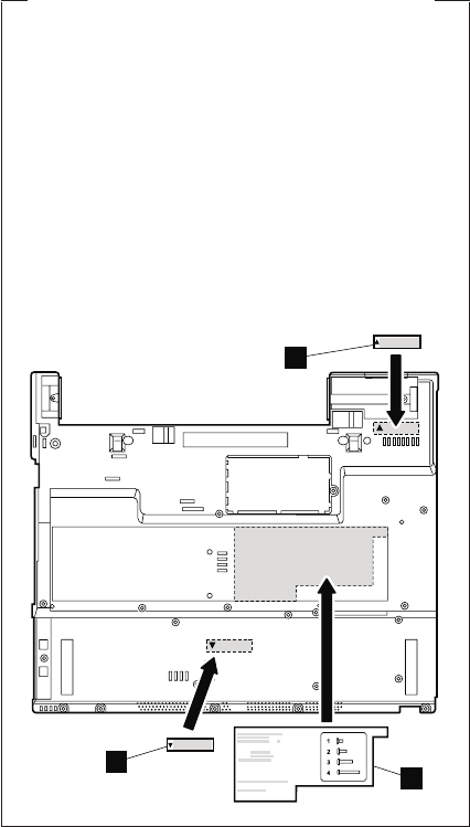
Note for sticking a label kit on the base cover
New base cover FRU is shipped with several kinds
of label kit. When you replace the base cover, you
need to stick a homologation label a which has
the same part no. with the label on the old base
cover (defective FRU) on the new base cover.
In some models, you also need to stick one or two
FCC labels b. Check the old base cover and if
there is one or two FCC labels on it, find the same
one from the label kit and stick it on the new base
cover.
Stick the labels on the new base cover as shown in
this figure.
a
b
b
Removing and replacing a FRU
144 T40/T40p, T41/T41p, T42/T42p
1270 System board, interposer card,
and base cover for 15.0-in. LCD models
For access, remove these FRUs, in order:
v “1020 Battery pack for 15.0-in. LCD models” on page 73
v “1030 Ultrabay Slim device” on page 74
v “1040 Hard disk drive” on page 75
v “1050 DIMM (optional)” on page 77
v “1060 Keyboard” on page 79
v “1070 DIMM (standard)” on page 83
v “1080 Modem daughter card (MDC/MDC-2)” on page 84
v “1090 Bluetooth/Modem daughter card
(BMDC/BMDC-2)” on page 86
v “1110 Keyboard bezel or Keyboard bezel with fingerprint
sensor (for 15.0-in. LCD models)” on page 91
v “1120 Mini PCI adapter” on page 97
v “1130 Fan assembly” on page 101
v “1150 Backup battery for 15.0-in. LCD models” on page
108
v “1160 Speaker assembly” on page 110
v “1190 PC Card slot assembly for 15.0-in. LCD models”
on page 116
v “1210 LCD assembly for 15.0-in. LCD models” on page
123
v “1220 CPU” on page 128
v “1240 Ultrabay Slim guide rail assembly for 15.0-in. LCD
models” on page 131
v “1250 VGA and Ultrabay Slim device eject button cable”
on page 134
Removing and replacing a FRU
ThinkPad T40/T40p, T41/T41p, T42/T42p Series 145
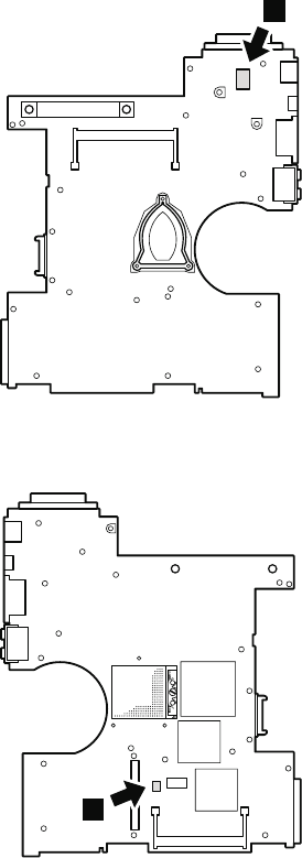
Important notice for handling the system board in
ThinkPad T42 series:
In ThinkPad T42 series, the security chip a is soldered
on the underside of the system board as in this figure.
a
In ThinkPad T42 series, accelerometer chip for the HDD
Active Protection System b is also soldered on the
topside of the system board.
b
Removing and replacing a FRU
146 T40/T40p, T41/T41p, T42/T42p

Important
When handling the system board in ThinkPad T42
series, bear the following in mind.
v The system board of the ThinkPad T42 series
has an accelerometer, which can be broken by
applying several thousands of G-forces.
Note: Dropping a system board from a height of
as little as 6 inches so that it falls flat on a
hard bench can subject the accelerometer
to as much as 6,000 G’s of shock.
v Be careful not to drop the system board on a
bench top that has a hard surface, such as metal,
wood, or composite.
v If a system board is dropped, you must test it,
using PC-Doctor for DOS, to make sure that the
HDD Active Protection still functions (see below).
Note: If the test shows that HDD Active
Protection is not functioning, be sure to
document the drop in any reject report,
and replace the system board.
v Avoid rough handling of any kind.
v At every point in the process, be sure not to drop
or stack the system board.
v If you put a system board down, be sure to put it
only on a padded surface such as an ESD mat or
conductive corrugated material.
After replacing the system board, run PC-Doctor for
DOS to make sure that HDD Active Protection still
functions. The procedure is as follows:
1. Place the computer on a horizontal surface.
2. Run Diagnostics --> Other Devices --> HDD
Active Protection Test.
Attention: Do not apply physical shock to the
computer while the test is running.
Removing and replacing a FRU
ThinkPad T40/T40p, T41/T41p, T42/T42p Series 147
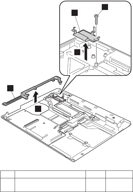
Remove the support structure a and the EMI bracket
b.
3
2
b
1
a
Step Screw (quantity) Color Torque
2 M2 × 10 mm, flat-head,
nylon-coated (1)
Black 0.245 Nm
(2.5 kgfcm)
(continued)
Removing and replacing a FRU
148 T40/T40p, T41/T41p, T42/T42p
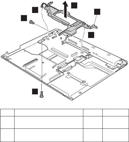
5
4
7
c
6
6
Step Screw (quantity) Color Torque
4 M2 × 10 mm, flat-head,
nylon-coated (1)
Black 0.245 Nm
(2.5 kgfcm)
5 M2.5 × 4.8 mm, bind-head,
nylon-coated (1)
Black 0.392 Nm
(4 kgfcm)
Remove two connectors 6 and then remove the cable
guide c in the direction of arrow 7.
When installing: Make sure that the connectors 6 are
firmly attached to the system board.
(continued)
Removing and replacing a FRU
ThinkPad T40/T40p, T41/T41p, T42/T42p Series 149
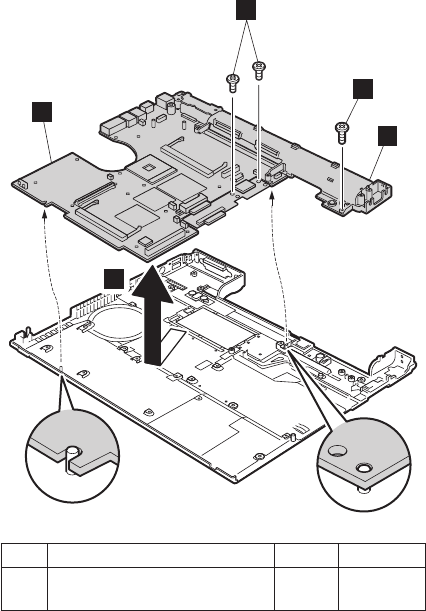
8
d
e
9
8
Step Screw (quantity) Color Torque
8 M2 × 4 mm, bind-head,
nylon-coated (3)
Black 0.245 Nm
(2.5 kgfcm)
In step 9, remove the I/O plate bracket (d) and the
system board (e) together.
When installing: Attach the system board so that the two
small projections on the base cover fit
into the holes provided, and then secure
the system board with the screw.
(continued)
Removing and replacing a FRU
150 T40/T40p, T41/T41p, T42/T42p
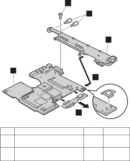
10
f
g
12
13
11
Step Screw (quantity) Color Torque
10 Hex stud (2) Silver 0.392 Nm
(4 kgfcm)
11 M2.5 × 3 mm, flat-head,
nylon-coated (1)
Gold 0.392 Nm
(4 kgfcm)
Remove the system board g from the I/O plate bracket
f in the direction of arrow 12. Then remove the
interposer card 13.
When installing: Make sure that the connectors of the
interposer card are firmly attached to the
system board.
Removing and replacing a FRU
ThinkPad T40/T40p, T41/T41p, T42/T42p Series 151
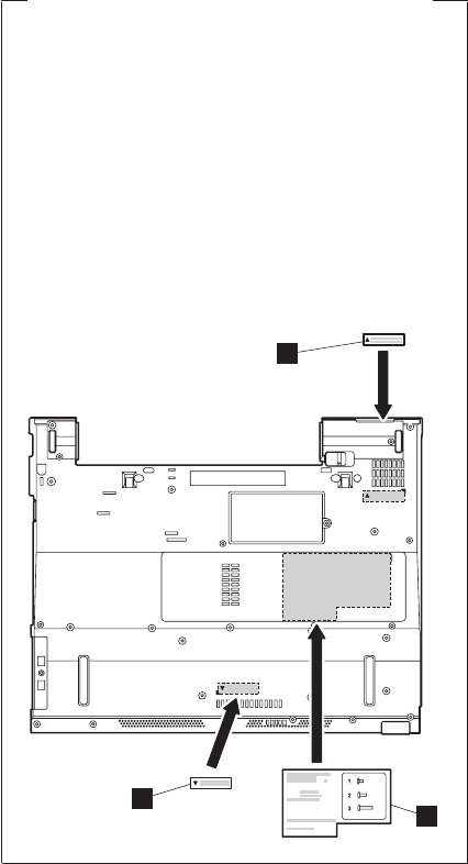
Note for sticking a label kit on the base cover
New base cover FRU is shipped with several kinds
of label kit. When you replace the base cover, you
need to stick a homologation label a which has
the same part no. with the label on the old base
cover (defective FRU) on the new base cover.
In some models, you also need to stick one or two
FCC labels b. Check the old base cover and if
there is one or two FCC labels on it, find the same
one from the label kit and stick it on the new base
cover.
Stick the labels on the new base cover as shown in
this figure.
a
b
b
Removing and replacing a FRU
152 T40/T40p, T41/T41p, T42/T42p
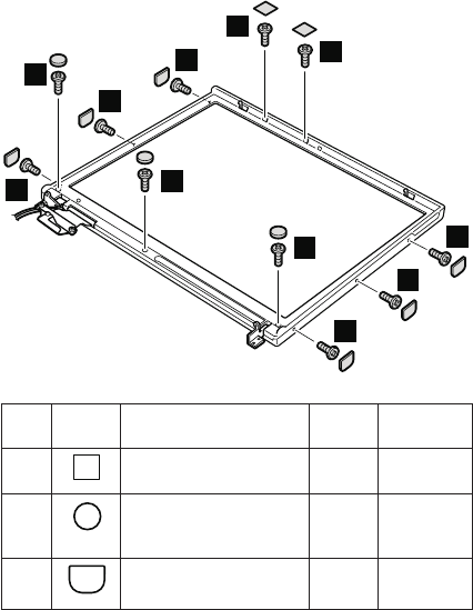
2010 LCD front bezel for 14.1-in. LCD
models
For access, remove these FRUs in order:
v “1010 Battery pack for 14.1-in. LCD models” on page 71
v “1040 Hard disk drive” on page 75
v “1060 Keyboard” on page 79
v “1090 Bluetooth/Modem daughter card
(BMDC/BMDC-2)” on page 86
v “1100 Palm rest or Palm rest with fingerprint sensor (for
14.1-in. LCD models)” on page 88
v “1120 Mini PCI adapter” on page 97
v “1170 Keyboard bezel for 14.1-in. LCD models” on page
112
v “1200 LCD assembly for 14.1-in. LCD models” on page
118
3
3
3
3
3
3
2
2
1
1
2
Step Screw
cap
Screw (quantity) Color Torque
1
M2 × 3 mm, pan-head,
nylon-coated (2)
Black 0.245 Nm
(2.5 kgfcm)
2
M2.5 × 4.8 mm,
bind-head, nylon-coated
(3)
Black 0.392 Nm
(4 kgfcm)
3
M2 × 3 mm, pan-head,
nylon-coated (6)
Black 0.245 Nm
(2.5 kgfcm)
(continued)
Removing and replacing a FRU
ThinkPad T40/T40p, T41/T41p, T42/T42p Series 153
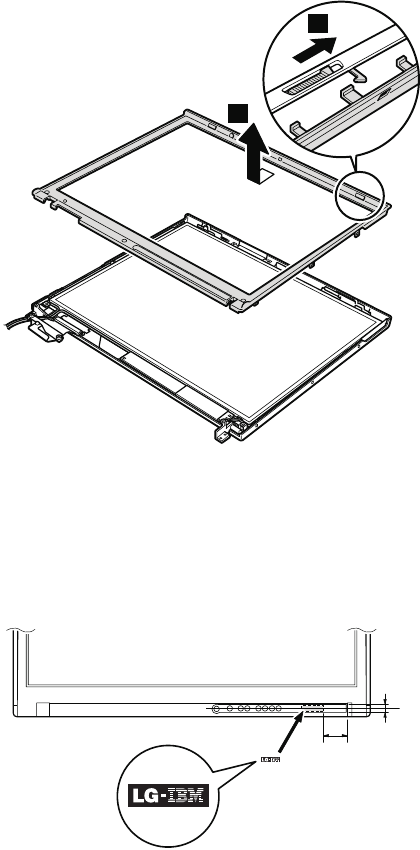
5
4
Note for LG-IBM models (Korea) in T41/T41p series:
New LCD front bezel FRU is shipped with clear plate FRU.
When you replace the LCD front bezel, you need to stick
the LG-IBM logo plate which is contained in the clear plate
FRU as shown in this figure.
21 mm
7 mm
Removing and replacing a FRU
154 T40/T40p, T41/T41p, T42/T42p
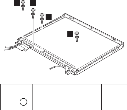
2020 LCD front bezel for 15.0-in. LCD
models
For access, remove these FRUs in order:
v “1020 Battery pack for 15.0-in. LCD models” on page 73
v “1040 Hard disk drive” on page 75
v “1060 Keyboard” on page 79
v “1090 Bluetooth/Modem daughter card
(BMDC/BMDC-2)” on page 86
v “1110 Keyboard bezel or Keyboard bezel with fingerprint
sensor (for 15.0-in. LCD models)” on page 91
v “1120 Mini PCI adapter” on page 97
v “1210 LCD assembly for 15.0-in. LCD models” on page
123
1
1
1
1
Step Screw
cap
Screw (quantity) Color Torque
1
M2 × 4 mm, bind-head,
nylon-coated (4)
Black 0.245 Nm
(2.5 kgfcm)
(continued)
Removing and replacing a FRU
ThinkPad T40/T40p, T41/T41p, T42/T42p Series 155
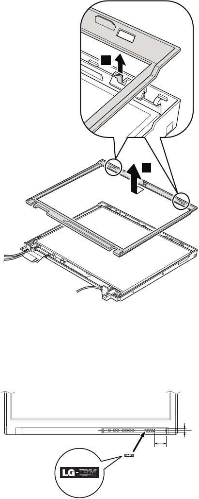
3
2
Note for LG-IBM models (Korea) in T42/T42p series:
New LCD front bezel FRU is shipped with clear plate FRU.
When you replace the LCD front bezel, you need to stick
the LG-IBM logo plate which is contained in the clear plate
FRU as shown in this figure.
21 mm
7 mm
Removing and replacing a FRU
156 T40/T40p, T41/T41p, T42/T42p

2030 Inverter card for 14.1-in. LCD
models
For access, remove these FRUs in order:
v “1010 Battery pack for 14.1-in. LCD models” on page 71
v “1040 Hard disk drive” on page 75
v “1060 Keyboard” on page 79
v “1090 Bluetooth/Modem daughter card
(BMDC/BMDC-2)” on page 86
v “1100 Palm rest or Palm rest with fingerprint sensor (for
14.1-in. LCD models)” on page 88
v “1120 Mini PCI adapter” on page 97
v “1170 Keyboard bezel for 14.1-in. LCD models” on page
112
v “1200 LCD assembly for 14.1-in. LCD models” on page
118
v “2010 LCD front bezel for 14.1-in. LCD models” on page
153
1
2
3
4
Step Screw (quantity) Color Torque
1 M2 × 3 mm, small-head,
nylon-coated (1)
Silver 0.245 Nm
(2.5 kgfcm)
When installing: Make sure that connectors 2 and 3
are firmly attached.
Removing and replacing a FRU
ThinkPad T40/T40p, T41/T41p, T42/T42p Series 157
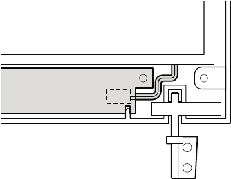
Cable routing: When replacing the inverter card, route
the connector cable as in this figure:
Removing and replacing a FRU
158 T40/T40p, T41/T41p, T42/T42p
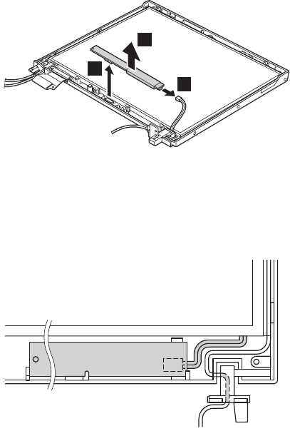
2040 Inverter card for 15.0-in. LCD
models
For access, remove these FRUs in order:
v “1020 Battery pack for 15.0-in. LCD models” on page 73
v “1040 Hard disk drive” on page 75
v “1060 Keyboard” on page 79
v “1090 Bluetooth/Modem daughter card
(BMDC/BMDC-2)” on page 86
v “1110 Keyboard bezel or Keyboard bezel with fingerprint
sensor (for 15.0-in. LCD models)” on page 91
v “1120 Mini PCI adapter” on page 97
v “1210 LCD assembly for 15.0-in. LCD models” on page
123
v “2020 LCD front bezel for 15.0-in. LCD models” on page
155
1
2
3
When installing: Make sure that connectors 2 and 3
are firmly attached.
Cable routing: When replacing the inverter card, route
the connector cable as in this figure:
Removing and replacing a FRU
ThinkPad T40/T40p, T41/T41p, T42/T42p Series 159
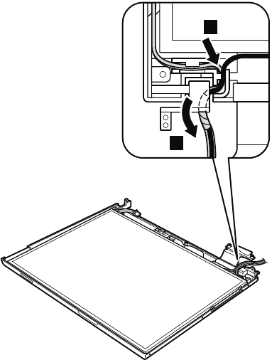
2050 Wireless antenna assemblies, LCD
panel, LCD cable assembly, hinges, and
LCD cover for 14.1-in. LCD models
For access, remove these FRUs in order:
v “1010 Battery pack for 14.1-in. LCD models” on page 71
v “1040 Hard disk drive” on page 75
v “1060 Keyboard” on page 79
v “1090 Bluetooth/Modem daughter card
(BMDC/BMDC-2)” on page 86
v “1100 Palm rest or Palm rest with fingerprint sensor (for
14.1-in. LCD models)” on page 88
v “1120 Mini PCI adapter” on page 97
v “1170 Keyboard bezel for 14.1-in. LCD models” on page
112
v “1200 LCD assembly for 14.1-in. LCD models” on page
118
v “2010 LCD front bezel for 14.1-in. LCD models” on page
153
v “2030 Inverter card for 14.1-in. LCD models” on page
157
Note: Step 1 to 5 are only for the models with the
Bluetooth wireless features. For the other models,
skip step 1 to 5.
2
1
(continued)
Removing and replacing a FRU
160 T40/T40p, T41/T41p, T42/T42p
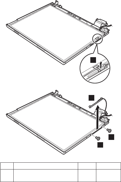
Peel the tape securing the Bluetooth wireless antenna
assembly 3.
3
5
4
4
Step Screw (quantity) Color Torque
4 M2 × 2.7 mm, small-head,
nylon-coated (2)
Yellow 0.245 Nm
(2.5 kgfcm)
(continued)
Removing and replacing a FRU
ThinkPad T40/T40p, T41/T41p, T42/T42p Series 161
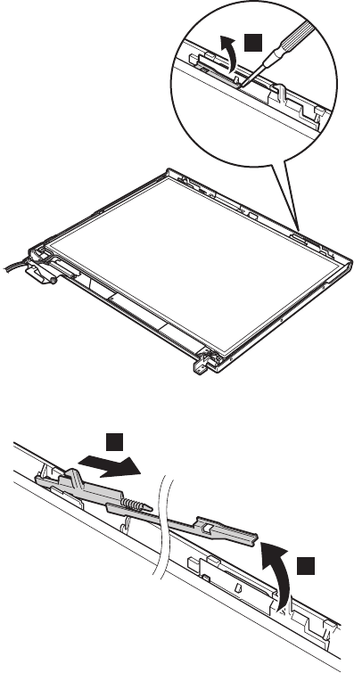
In step 6, remove the latch bar as in this figure.
6
Lift the latch bar in the direction of the arrow 7, and then
remove the left latch in the direction of the arrow 8.
7
8
(continued)
Removing and replacing a FRU
162 T40/T40p, T41/T41p, T42/T42p
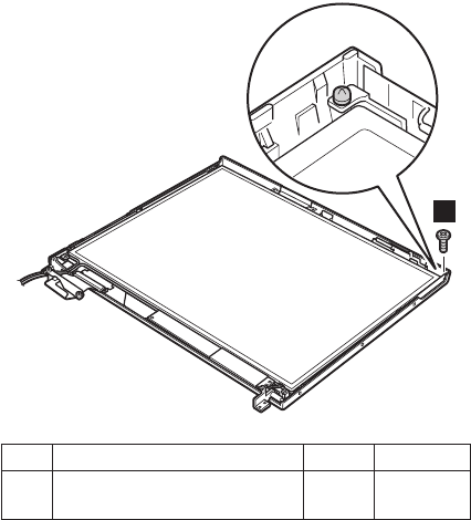
9
Step Screw (quantity) Color Torque
9 M2 × 3 mm, small-head,
nylon-coated (1)
Silver 0.245 Nm
(2.5 kgfcm)
(continued)
Removing and replacing a FRU
ThinkPad T40/T40p, T41/T41p, T42/T42p Series 163
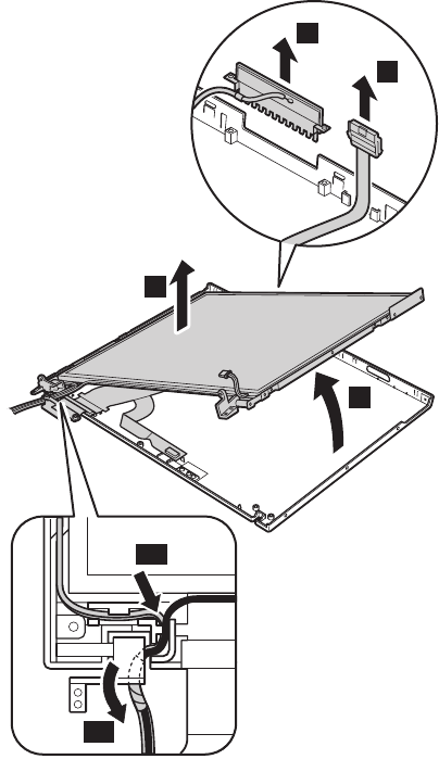
Slide the spiral tube binding the antenna cables (10a),
and then release the cables from the cable guide (10b).
Lift the LCD panel in the direction of arrow 11, and
detach the wireless LAN antenna 12 and the ThinkLight
13. Then remove the LCD panel in the direction of arrow
14.
11
14
13
12
10b
10a
(continued)
Removing and replacing a FRU
164 T40/T40p, T41/T41p, T42/T42p
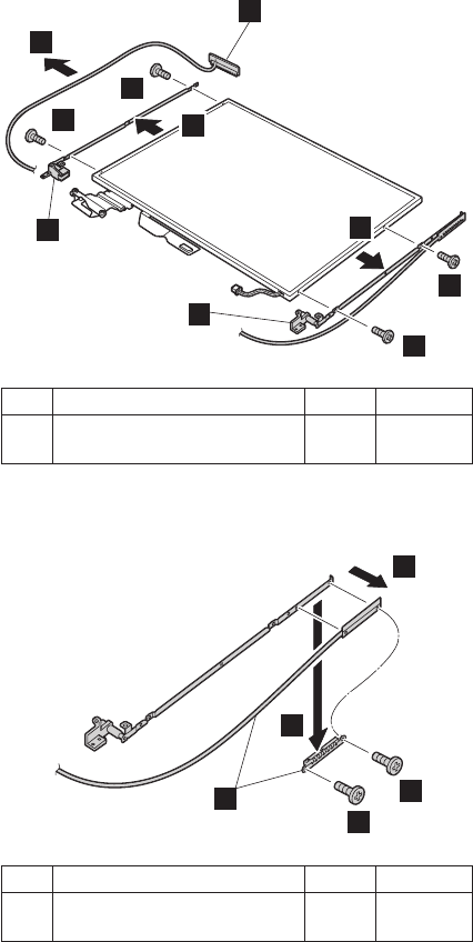
Remove the antenna assembly a and hinges b from
the LCD assembly.
15
a
16
b
16 17
17
b
16
16
Step Screw (quantity) Color Torque
16 M2 × 3 mm, small-head,
nylon-coated (4)
Silver 0.245 Nm
(2.5 kgfcm)
Remove two screws c, and detach the wireless AUX
antenna cable (c) from the right hinge.
18
18
19
20
c
Step Screw (quantity) Color Torque
18 M2 × 3 mm, small-head,
nylon-coated (2)
Silver 0.245 Nm
(2.5 kgfcm)
(continued)
Removing and replacing a FRU
ThinkPad T40/T40p, T41/T41p, T42/T42p Series 165
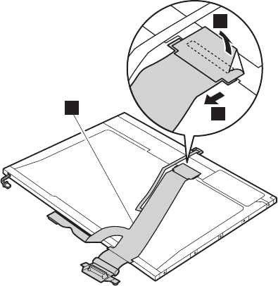
Turn over the LCD panel and strip off the tape 21
securing the FPC (c). Then detach the connector 22 in
the direction of the arrow.
22
c
21
(continued)
Removing and replacing a FRU
166 T40/T40p, T41/T41p, T42/T42p
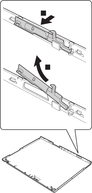
Remove the right latch from the LCD cover.
23
24
Removing and replacing a FRU
ThinkPad T40/T40p, T41/T41p, T42/T42p Series 167
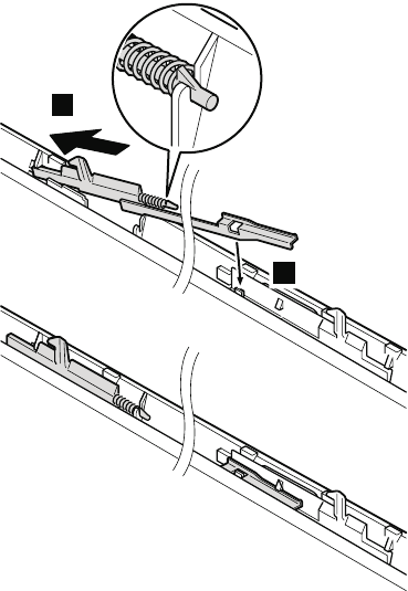
When installing: Follow these steps when you
reassemble the LCD unit.
1. Attach the left latch to the LCD cover.
2
1
(continued)
Removing and replacing a FRU
168 T40/T40p, T41/T41p, T42/T42p
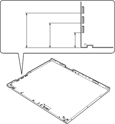
2. Paste three gaskets only for the models with Bluetooth
wireless features. For the other models, skip this step.
41.5 mm
68.5 mm
95.5 mm
3. Connect the LCD cable assembly to the LCD panel
and secure it with the tape.
4. Attach the wireless LAN antenna cables (MAIN, AUX)
and the hinges to the LCD panel.
5. Attach the LCD panel to the LCD cover.
(continued)
Removing and replacing a FRU
ThinkPad T40/T40p, T41/T41p, T42/T42p Series 169
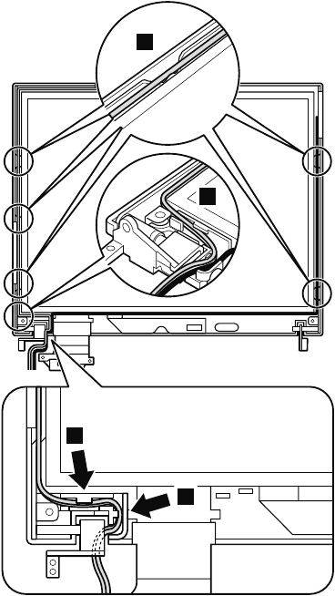
6. Route the wireless LAN antenna cables as in the
following drawings:
a.
3
3
2
1
(continued)
Removing and replacing a FRU
170 T40/T40p, T41/T41p, T42/T42p
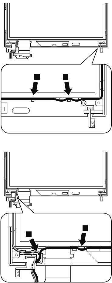
b.
4 4
c.
5
5
(continued)
Removing and replacing a FRU
ThinkPad T40/T40p, T41/T41p, T42/T42p Series 171
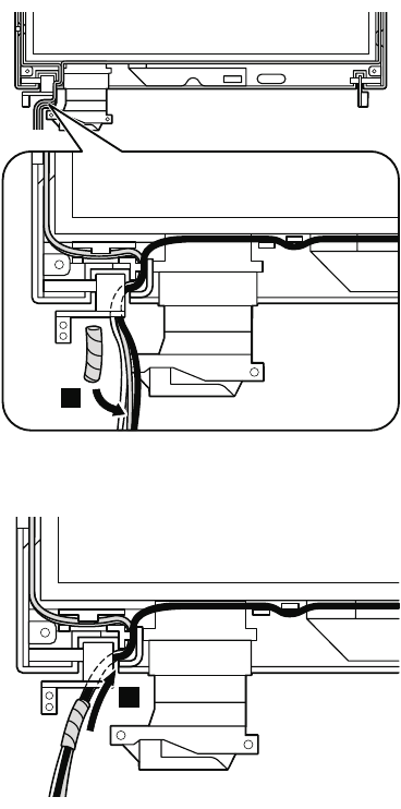
d. Coil the spiral tube round the antenna cables.
6
e. Slide the spiral tube in the direction shown by
arrow 7.
7
(continued)
Removing and replacing a FRU
172 T40/T40p, T41/T41p, T42/T42p
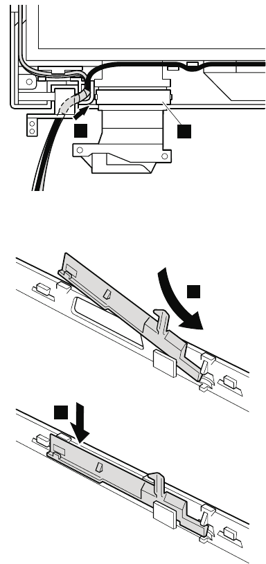
Move the spiral tube until it reaches at the cable guide
of the LCD cover as in this figure. Make sure that the
antenna cable is not pinched by cable clip (a).
8a
7. Secure the LCD panel with the screws.
8. Attach the right latch to the LCD cover.
1
2
Removing and replacing a FRU
ThinkPad T40/T40p, T41/T41p, T42/T42p Series 173
Note for LG-IBM models (Korea) in T40/T40p series:
New LCD cover FRU is shipped with the LG-IBM logo
plate. When you replace the LCD cover, you need to stick
the LG-IBM logo plate as shown in this figure.
10 mm
15 mm
Note for LG-IBM models (Korea) in T41/T41p series:
New LCD cover FRU is shipped with clear plate FRU.
When you replace the LCD cover, you need to stick the
LG-IBM logo plate which is contained in the clear plate
FRU as shown in this figure.
22 mm
16 mm
Removing and replacing a FRU
174 T40/T40p, T41/T41p, T42/T42p
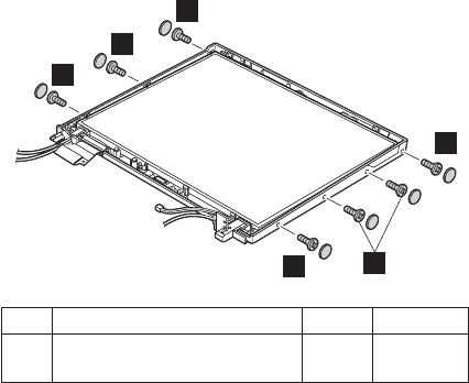
2060 Wireless antenna assemblies, LCD
panel, LCD cable assembly, hinges, and
LCD cover for 15.0-in. LCD models
For access, remove these FRUs in order:
v “1020 Battery pack for 15.0-in. LCD models” on page 73
v “1040 Hard disk drive” on page 75
v “1060 Keyboard” on page 79
v “1090 Bluetooth/Modem daughter card
(BMDC/BMDC-2)” on page 86
v “1110 Keyboard bezel or Keyboard bezel with fingerprint
sensor (for 15.0-in. LCD models)” on page 91
v “1120 Mini PCI adapter” on page 97
v “1210 LCD assembly for 15.0-in. LCD models” on page
123
v “2020 LCD front bezel for 15.0-in. LCD models” on page
155
v “2040 Inverter card for 15.0-in. LCD models” on page
159
1
1
1
1
1
1
Step Screw (quantity) Color Torque
1 M2 × 4 mm, bind-head,
nylon-coated (7)
Black 0.245 Nm
(2.5 kgfcm)
(continued)
Removing and replacing a FRU
ThinkPad T40/T40p, T41/T41p, T42/T42p Series 175
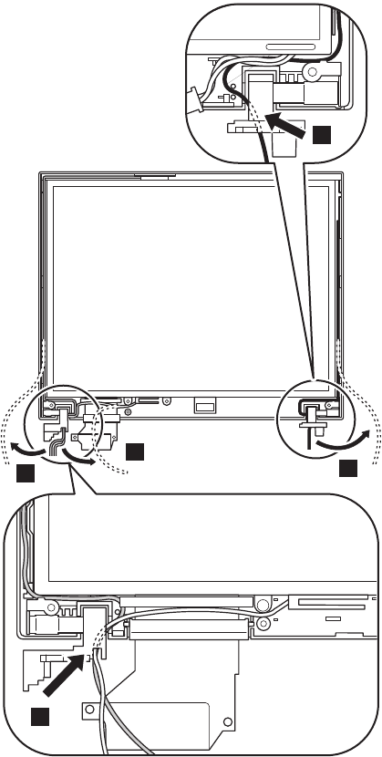
Release the antenna cables 2. At the parts indicated by
arrows a, the antenna cables go through the hinges.
When you route the antenna cables, attach the cables
firmly.
a
a
2
2
2
(continued)
Removing and replacing a FRU
176 T40/T40p, T41/T41p, T42/T42p
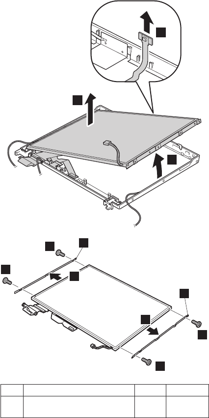
3
4
5
6
6
6b
67
7
b
Step Screw (quantity) Color Torque
6 M2 × 3 mm, bind-head,
nylon-coated (4)
Silver 0.245 Nm
(2.5 kgfcm)
(continued)
Removing and replacing a FRU
ThinkPad T40/T40p, T41/T41p, T42/T42p Series 177
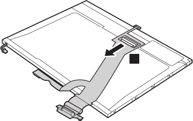
Turn over the LCD panel, and detach the connector 8 in
the direction of the arrow.
8
When installing: Make sure that the FPC connector is
firmly attached to the LCD panel.
(continued)
Removing and replacing a FRU
178 T40/T40p, T41/T41p, T42/T42p
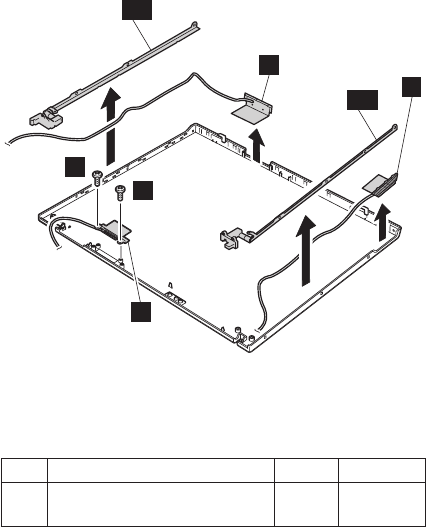
9
11
10b 12
9
d
10a
Note: Step 9 is only for the models with the Bluetooth
wireless features. For the other models, skip this
step.
Step Screw (quantity) Color Torque
9 M2 × 4 mm, bind-head,
nylon-coated (2)
Black 0.245 Nm
(2.5 kgfcm)
Remove the hinges 10a, 10b and the wireless LAN
antenna cables 11, 12
(continued)
Removing and replacing a FRU
ThinkPad T40/T40p, T41/T41p, T42/T42p Series 179
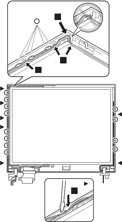
Cable routing: When you reassemble the LCD unit, do as
follows:
At the left-top corner of the LCD unit, route the antenna
cable as in a. Do not route the cable over the bracket.
To do so, the cable might be pinched between the LCD
front bezel and the LCD cover, and the cable or the other
parts might be damaged or might not be installed properly.
At the points shown as V, route the cable as it goes under
the projections as in b. At the points shown as , push
the cable into the ditch between the LCD cover and the
bracket by using a screwdriver as in c.
c
a
b
b
(continued)
Removing and replacing a FRU
180 T40/T40p, T41/T41p, T42/T42p
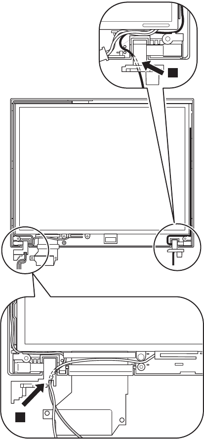
Then route the cables to along the cable guides of the
LCD cover. When you route the cables around the LCD
hinges, do as shown in c.
c
c
Removing and replacing a FRU
ThinkPad T40/T40p, T41/T41p, T42/T42p Series 181
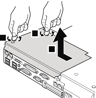
3010 ThinkPad Dock II PCI cover
1
2
1
(Bottom view)
Removing and replacing a FRU
182 T40/T40p, T41/T41p, T42/T42p
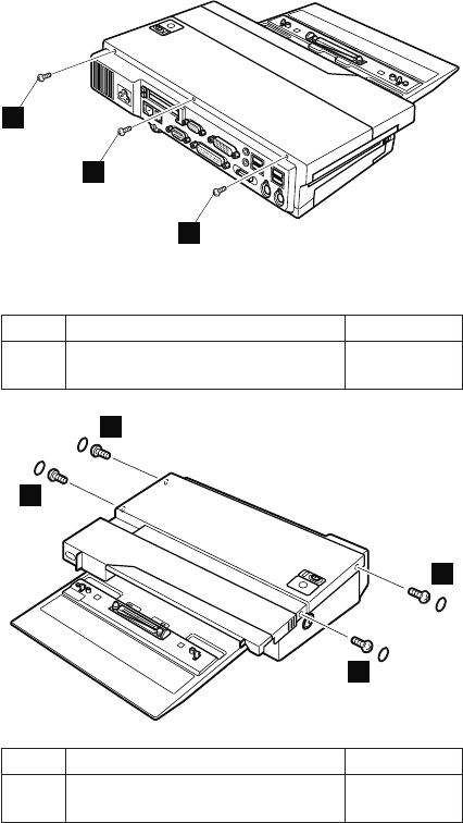
3020 ThinkPad Dock II top cover
1
1
1
(Rear view)
Step Screw (quantity) Torque
1 M2.5 × 4.8 mm (3) 0.392 Nm
(4 kgfcm)
2
2
2
2
Step Screw (quantity) Torque
2 M2.5 × 4.8 mm (4) 0.392 Nm
(4 kgfcm)
(continued)
Removing and replacing a FRU
ThinkPad T40/T40p, T41/T41p, T42/T42p Series 183
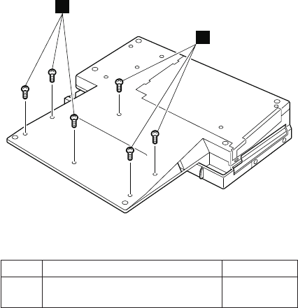
3
3
(Bottom view)
Step Screw (quantity) Torque
3 M2.5 × 4.8 mm (6) 0.392 Nm
(4 kgfcm)
(continued)
Removing and replacing a FRU
184 T40/T40p, T41/T41p, T42/T42p
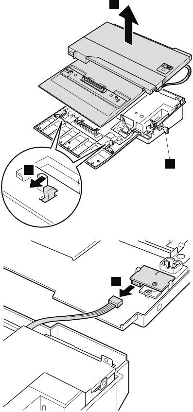
Make sure that the system lock key A is set to the
Unlock position. Release the front latches in step 4, and
then remove the top cover 5. Then detach the connector
cable 6 as in the figure.
4
5
A
6
Removing and replacing a FRU
ThinkPad T40/T40p, T41/T41p, T42/T42p Series 185

Locations
Front view
1 Wireless status indicator
2 Bluetooth wireless status indicator (for some
models)
3 System status indicators
4 Power status indicators
5 External monitor connector
6 Ultrabay Slim status indicator
7 Ultrabay Slim latch
8 Ultrabay Slim device eject lever
9 Ultrabay Slim
10 TrackPoint pointing stick
11 Fingerprint sensor (for some models)
12 TrackPoint buttons
13 Touch pad buttons
14 Touch pad
15 UltraNav
16 Access IBM button
17 Volume control buttons
18 Power switch
19 ThinkLight
Locations
186 T40/T40p, T41/T41p, T42/T42p
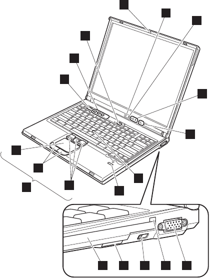
1
2
3
4
56789
16
10
12
13
14
15
19
17
18
11
Locations
ThinkPad T40/T40p, T41/T41p, T42/T42p Series 187
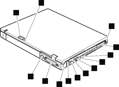
Rear view
1 Power status indicators
2 Bluetooth wireless status indicator
3 PC Card eject buttons
4 PC Card slots
5 Microphone jack
6 Stereo headphone jack
7 RJ-45 (Ethernet) connector
8 RJ-11 (modem) connector
9 TV-out connector
10 Universal serial bus (USB) connectors
11 Security keyhole
12 Parallel connector
13 AC power connector
1
2
11 1012
8
9
13
7
6
5
4
3
Locations
188 T40/T40p, T41/T41p, T42/T42p
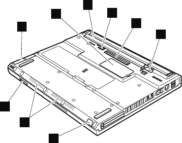
Bottom view
1 Hard disk drive
2 Optional DIMM slot
3 Battery pack
4 Battery pack lock (only for 14.1-in LCD models)
5 Docking connector
6 Battery pack latch
7 Infrared port
8 Built-in stereo speakers
9 LCD latch
3
4
7
9
1
2
5
6
8
Locations
ThinkPad T40/T40p, T41/T41p, T42/T42p Series 189

Parts list
v Each FRU is available for all types or models, unless
specific types or models are specified.
v A CRU (customer replaceable unit) is identified by a
single asterisk (*) or two asterisks (**) in the CRU ID
column. An N in the CRU ID column means the part is
not a CRU. A single asterisk (*) means the part is a Tier
1 CRU; two asterisks (**) means the part is a Tier 2
CRU.
v FRUs marked with OP are available as options.
Parts list
190 T40/T40p, T41/T41p, T42/T42p
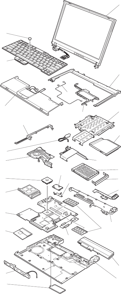
Overall
1
2
3
4
5
6
7
11
10
12
13
16
14
15
18
a
20
21
22
17
9
23
19
b
f
c
d
e
8
Parts list
ThinkPad T40/T40p, T41/T41p, T42/T42p Series 191

No. FRU P/N CRU
ID
a- f See “Miscellaneous parts” on page 243.
1 LCD unit (see “14.1-in. LCD FRUs” on page 220
and “15.0-in. LCD FRUs” on page 230.)
N
2 Keyboard bezel assembly (14.1-in.) 91P9540 N
Keyboard bezel assembly (15.0-in.) 13R2921 N
Keyboard bezel assembly with fingerprint
sensor (15.0-in.)
v 2373-F2x, F3x, F4x, F5x, H8x, H9x,
HAx, HBx, JBx, KKx, L1x, L2x, L3x,
L4x, L5x, L6x, L7x, L8x, N1x, N2x,
N3x, N4x, N5x, Q1x, Q2x, Q3x, Q4x,
Q5x, Q6x
v 2374-L1x, Q2x
v 2378-R2x, R8x, R9x, RSx, RTx, RUx,
RVx
v 2379-R8x, R9x, RUx, RVx
91P8685 N
3 Ultrabay guide rail assembly (14.1-in.) 91P8394 N
Ultrabay guide rail assembly (15.0-in.) 13R2920 N
Ultrabay guide rail assembly with
fingerprint sensor model (14.1-in.)
v 2373-F1x, H1x, H2x, H3x, H4x, H5x,
H6x, H7x, J4x, J6x, J7x, J8x, J9x,
JAx, K1x, K2x, K3x, K5x, K6x, K7x,
K8x, K9x, KAx, KBx, KCx, KDx, KEx,
KFx, KGx, KHx, KJx, KLx, KMx, KNx,
KPx, KQx, M1x, M2x, M3x, M4x, M5x,
M6x, P1x, P2x, P3x, P4x
v 2374-J4x, K1x, K2x, K5x
v 2378-R1x, R5x, RPx, RQx, RRx
v 2379-R1x, R5x
91P8682 N
Ultrabay guide rail assembly with
fingerprint sensor model (15.0-in.)
v 2373-F2x, F3x, F4x, F5x, H8x, H9x,
HAx, HBx, JBx, KKx, L1x, L2x, L3x,
L4x, L5x, L6x, L7x, L8x, N1x, N2x,
N3x, N4x, N5x, Q1x, Q2x, Q3x, Q4x,
Q5x, Q6x
v 2374-L1x, Q2x
v 2378-R2x, R8x, R9x, RSx, RTx, RUx,
RVx
v 2379-R8x, R9x, RUx, RVx
91P8683 N
(continued)
Parts list
192 T40/T40p, T41/T41p, T42/T42p

No. FRU P/N CRU
ID
4 DVD drive 8x for T40/T40p, T41/T41p, T42 OP
v 2373-14x, 16x, 1Bx, 24x, 2Bx, 47x, 54x, 58x, 61x, 66x,
6Bx, 6Dx, 81x, 82x, 85x, 86x, 88x, 8Ax, 8Cx, 8Dx, BDx,
C1x, C7x, C8x, CAx
v 2373-1Hx, 1Lx, 5Hx, 6Kx, 6Sx, 8Hx, 8Jx, 8Kx, 8Px, 8Rx,
8Sx
v 2373-1Ux, 1Yx, 2Tx, 2Yx, 2Zx, 6Ux, 8Tx, 8Vx, HYx, KZx
v 2373-JEx, K2x, K3x, K8x, KAx, Q3x
v 2374-14x, 82x, 8Cx
v 2374-1Hx, 8Rx
v 2374-8Tx
v 2374-K2x
v 2378-D1U, D2U
v 2378-DEx, DFx
v 2378-DTx, DVx
v 2378-R3x, R7x
HLDS 92P6579 *
TEAC 92P5991 *
DVD/CD-RW combo drive for T40/T40p, T41/T41p OP
v 2373-12x, 19x, 22x, 25x, 29x, 2Ax, 2Cx, 33x, 42x, 44x,
4Ax, 4Bx, 4Cx, 51x, 71x, 72x, 75x, 76x, 78x, 7Ax, 7Cx,
91x, 92x, 93x, 94x, 96x, 9Cx, B2x, B5x, C3x, C4x, G1x,
G2x, G3x, G4x, G5x, G6x
v 2373-1Ex, 1Fx, 2Ex, 2Fx, 2Qx, 3Fx, 3Hx, 3Px, 4Fx, 4Gx,
4Hx, 4Px, 4Qx, 4Sx, 5Qx, 5Rx, 7Ex, 7Fx, 7Jx, 7Kx, 7Mx,
7Px, 9Ex, 9Fx, 9Gx, 9Hx, 9Kx, BFx, BHx, BJx, GEx,
GGx, GHx, GJx, GKx, GLx, GMx
v 2374-12x, 72x, 7Cx
v 2374-1Fx, 3Hx, 4Hx, 7Fx, 7Jx, GGx
v 2375-72x
v 2376-72x
v 2378-DGx, DHx, DJx, DKx
v 2379-D3x, D4x, D5x, D6x
KME 92P6581 *
Toshiba 92P5993 *
(continued)
Parts list
ThinkPad T40/T40p, T41/T41p, T42/T42p Series 193

No. FRU P/N CRU
ID
4 DVD/CD-RW combo drive for T42/T42p OP
v 2373-1Wx, 1Zx, 2Ux, 2Wx, 2Xx, 3Ux, 3Wx, 3Xx, 3Yx,
3Zx, 4Tx, 4Vx, 4Wx, 4Yx, 4Zx, 5Tx, 5Wx, 5Xx, 6Vx, 6Yx,
6Zx, 7Tx, 7Vx, 7Wx, 7Yx, 7Zx, 8Xx, 8Yx, 8Zx, 9Tx, 9Ux,
9Vx, 9Xx, CUx, CVx, CWx, CXx, FWx, FYx, GVx, GXx,
GYx, GZx, HVx, JTx, JXx, KUx, KYx
v 2373-F1x, F2x, JAx, JBx, JCx, JDx, JFx, K1x, K5x, K7x,
K9x, KBx, KCx, KEx, KFx, KGx, KHx, KJx, KKx, KLx,
KMx, KNx, KPx, KQx, L1x, L2x, L4x, L5x, L6x, L7x, L8x,
M1x, M2x, M3x, N1x, N2x, N3x, P2x, P4x, Q2x, Q5x
v 2374-1Wx, 3Xx, 4Wx, 6Vx, 6Yx
v 2374-J4x, K1x, K5x, L1x, Q2x,
v 2378-2Xx, 5Ux, DUx, DWx, DXx, FUx, FVx, FTx, FZx
v 2378-R1x, R2x, R4x, R5x, R6x, R8x, R9x
v 2379-5Vx, DZx, DXx
v 2379-R1x, R6x, R8x, R9x
PCC 13N6771 *
HLDS 13N6769 *
DVD-RAM/RW drive (PCC) for T42/T42p
OP
v 2373-3Vx, 4Ux, 7Xx, 9Zx, CYx, GRx,
GSx, GTx, GUx, HTx, HXx, HWx, KTx,
KXx
v 2373-F3x, F4x, F5x, KDx, L3x, M4x,
M5x, M6x, N4x, N5x, P1x, P3x, Q1x,
Q4x, Q6x
v 2374-3Vx, 7Xx, HTx
v 2378-DYx
v 2379-DYx
92P6110 *
Travel cover
v All models with suffix -xxE and -xxJ
13N5108 *
For optional Ultrabay devices, see “Optional FRUs” on page
247.
5 Hard disk drive, 20 GB, 9.5 mm, 4,200 rpm for T40/T40p
v Supported by CTO
ThinkPad STD OP 92P6327 *
Fujitsu 27L4385 *
Hard disk drive, 20 GB, 9.5 mm, 4,200
rpm, HGST for T42/T42p
v Supported by CTO
13N6701 *
(continued)
Parts list
194 T40/T40p, T41/T41p, T42/T42p

No. FRU P/N CRU
ID
5 Hard disk drive, 30 GB, 9.5 mm, 4,200
rpm, ThinkPad STD for T40/T40p
v 2373-12x, 14x, 16x, 19x, 1Bx, 51x,
58x, 61x, 66x, 6Bx, 6Dx, C1x
v 2374-12x, 14x
v 2378-D1U, D2U
v 2379-D3U
92P6330 *
Hard disk drive, 30 GB, 9.5 mm, 4,200
rpm, Fujitsu
v 2373-12x, 14x, 16x, 19x, 1Bx, 51x,
58x, 61x, 66x, 6Bx, 6Dx, C1x
v 2373-1Ex, 1Fx, 1Hx, 1Lx, 5Qx, 5Rx,
6Kx, 6Sx
v 2373-1Ux, 1Wx, 1Yx, 1Zx, 5Wx
v 2374-12x, 14x
v 2374-1Hx, 1Fx
v 2374-1Wx
v 2378-D1U, D2U
v 2378-DEx
v 2378-DTx, DVx, FUx
v 2379-D3U
92P6036 *
Hard disk drive, 30 GB, 9.5 mm, 4,200
rpm, HGST for T41/T41p, T42
v 2373-1Fx, 1Hx, 6Kx, 6Sx, 5Qx, 5Rx
v 2373-1Ux, 1Wx, 1Yx, 1Zx, 5Wx
v 2373-JAx, JBx
v 2374-1Hx, 1Fx
v 2374-1Wx
v 2374-J4x
v 2378-2Zx, DTx, DVx, FUx
v 2378-R3x, R7x
13N6703 *
Hard disk drive, 40 GB, 9.5 mm, 5,400
rpm, Hitachi for T40/T40p
v 2373-22x, 24x, 25x, 29x, 2Ax, 2Bx,
42x, 44x, 47x, 49x, 4Ax, 4Bx, 54x,
71x, 72x, 75x, 76x, 78x, 7Ax, 7Cx,
81x, 82x, 85x, 86x, 88x, 8Ax, 8Cx,
8Dx, B2x, B5x, BDx, C3x, C4x, C7x,
C8x, CAx, G1x, G2x
v 2374-2Ax, 2Cx, 44x, 4Cx, 72x, 75x,
7Cx, 82x, 8Cx
v 2375-72x
v 2376-72x
v 2379-D4U, D6U
08K9834 *
(continued)
Parts list
ThinkPad T40/T40p, T41/T41p, T42/T42p Series 195

No. FRU P/N CRU
ID
5 Hard disk drive, 40 GB, 9.5 mm, 5,400
rpm ThinkPad STD for T40/T40p,
T41/T41p OP
v 2373-22x, 24x, 25x, 29x, 2Ax, 2Bx,
42x, 44x, 47x, 49x, 4Ax, 4Bx, 54x,
71x, 72x, 75x, 76x, 78x, 7Ax, 7Cx,
81x, 82x, 85x, 86x, 88x, 8Ax, 8Cx,
8Dx, B2x, B5x, BDx, C3x, C4x, C7x,
C8x, CAx, G1x, G2x
v 2373-2Ex, 2Fx, 2Px, 2Qx, 3Hx, 3Px,
4Fx, 4Gx, 4Hx, 4Nx, 4Px, 4Qx, 4Rx,
5Hx, 7Ex, 7Fx, 7Jx, 7Kx, 7Mx, 7Px,
8HU, 8Jx, 8Kx, 8Px, 8Rx, 8Sx, BFx,
BJx, BHx
v 2374-2Ax, 2Cx, 44x, 4Cx, 72x, 75x,
7Cx, 82x, 8Cx
v 2374-4Hx, 7Fx, 7Jx, 8Rx
v 2375-72x
v 2376-72x
v 2378-DEx, DFx, DGx, DHx, DKx
v 2379-D4U, D6U
92P6342 *
Hard disk drive, 40 GB, 9.5 mm, 5,400 rpm for T40/T40p,
T41/T41p, T42
v 2373-22x, 24x, 25x, 29x, 2Ax, 2Bx, 42x, 44x, 47x, 49x,
4Ax, 4Bx, 54x, 71x, 72x, 75x, 76x, 78x, 7Ax, 7Cx, 81x,
82x, 85x, 86x, 88x, 8Ax, 8Cx, 8Dx, B2x, B5x, BDx, C3x,
C4x, C7x, C8x, CAx, G1x, G2x
v 2373-2Ex, 2Fx, 2Px, 2Qx, 3Hx, 3Px, 4Fx, 4Gx, 4Hx, 4Nx,
4Px, 4Qx, 4Rx, 5Hx, 7Ex, 7Fx, 7Jx, 7Kx, 7Mx, 7Px, 8HU,
8Jx, 8Kx, 8Px, 8Rx, 8Sx, BFx, BJx, BHx
v 2373-2Tx, 2Ux, 2Wx, 2Xx, 2Yx, 3Ux, 3Wx, 3Xx, 3Yx,
4Tx, 4Ux, 4Wx, 4Yx, 4Zx, 5Tx, 5Xx, 6Ux, 6Vx, 6Wx, 6Yx,
6Zx, 7Tx, 7Vx, 7Wx, 7Yx, 7Zx, 8Tx, 8Ux, 8Vx, 8Xx, 8Yx,
8Zx, FTx, FVx, FWx, FYx, JTx, JXx
v 2373-F1x, F2x, F5x, JCx, JDx, JEx, JFx, K1x, K2x, K3x,
K5x, K6x, K7x, K8x, K9x, KAx, KBx, KCx, KDx, KEx,
KGx, KHx, KJx, KLx, KNx, L1x, L2x, L3x, L4x, L5x, L6x,
L7x
v 2374-2Ax, 2Cx, 44x, 4Cx, 72x, 75x, 7Cx, 82x, 8Cx
v 2374-4Hx, 7Fx, 7Jx, 8Rx
v 2374-3Xx, 4Wx, 6Vx, 6Yx, 8Tx
v 2374-K1x, K2x, K5x, L1x
v 2375-72x
v 2376-72x
v 2378-DEx, DFx, DGx, DHx, DKx
v 2378-2Xx, 5Ux, DUx, DWx, DXx, FZx
v 2378-R1x, R2x, R4x, R5x, R6x, R8x
v 2379-D4U, D6U
v 2379-5Vx, DXx, DZx
v 2379-R1x, R5x, R6x, R8x
HGST 13N6801 *
Fujitsu 13N6773 *
(continued)
Parts list
196 T40/T40p, T41/T41p, T42/T42p

No. FRU P/N CRU
ID
5 Hard disk drive, 60 GB, 9.5 mm, 4,200
rpm, HGST for T40/T40p, T41/T41p
v Supported by CTO
13N6707 *
Hard disk drive, 60 GB, 9.5 mm, 5,400
rpm, HGST for T42/T42p
v 2373-KPx, KQx, L3x, L8x
13N6803 *
Hard disk drive, 60 GB, 9.5 mm, 7,200
rpm, HGST for T41/T41p, T42/T42p
v 2373-3Fx, 4Sx, 9Ex, 9Fx, 9Gx, 9Jx,
9Hx, 9Kx, GEx, GGx, GHx, GJx, GKx,
GLx
v 2373-GRx, GSx, GTx, GUx, GVx,
GXx, GYx, HTx, HVx, HWx, HXx,
HYx, KTx, KUx, KXx, KZx
v 2373-F4x, KKx, M3x, N3x, P1x, P2x,
P3x, P4x, Q1x, Q2x, Q3x, Q4x, Q5x
v 2374-GGx
v 2374-HTx
v 2374-Q2x
v 2378-R9x
v 2379-R9x
13N6807 *
Hard disk drive, 80 GB, 9.5 mm, 4,200
rpm, ThinkPad STD for T40 OP
v 2373-32x, 33x, 91x, 92x, 93x, 94x,
96x, 9Cx
v 2374-9Cx
v 2379-D5U
13N6709 *
Hard disk drive, 80 GB, 9.5 mm, 5,400
rpm, HGST for T41p, T42/T42p
v 2373-GMx
v 2373-3Vx, 3Zx, 4Vx, 7Xx, 9Tx, 9Ux,
9Vx, 9Xx, 9Zx, CUx, CVx, CWx, CXx,
CYx, GZx
v 2374-3Vx, 7Xx
v 2378-DYx, EWx, EXx, EYx, EZx
v 2379-DYx, EYx, EZx
13N6805 *
Hard disk drive, 80 GB, 9.5 mm, 5,400
rpm, Fujitsu for T41p, T42/T42p
v 2373-CUx, CVx, CWx, CXx, CYx
v 2373-F3x, KFx, KMx, M1x, M2x, M4x,
M5x, M6x, N1x, N2x, N3x, N4x, N5x,
Q6x
v 2374-7Xx
v 2378-DYx, EWx, EXx, EYx, EZx, FZx
v 2379-DYx, EYx, EZx
13N6793 *
6 Cover, Hard disk drive (14.1-in.) 13N5530 *
Cover, Hard disk drive (15.0-in.) 13R2922 *
7 VGA and Ultrabay eject button cable
(14.1-in.)
91P6788 N
VGA and Ultrabay eject button cable
(15.0-in.)
91P6828 N
(continued)
Parts list
ThinkPad T40/T40p, T41/T41p, T42/T42p Series 197

No. FRU P/N CRU
ID
8 Modem daughter card (MDC) for
T40/T40p, T41/T41p
v 2373-12x, 14x, 16x, 19x, 1Bx, 22x,
24x, 25x, 29x, 2Ax, 2Bx, 2Cx, 3Cx,
44x, 47x, 49x, 4Bx, 4Cx, 51x, 54x,
58x, 61x, 66x, 6Bx, 6Dx, 71x, 72x,
75x, 76x, 78x, 7Ax, 7Cx, 81x, 82x,
85x, 86x, 88x, 8Ax, 8Cx, 8Dx, 91x,
A3x, A4x, A5x, A6x, A7x, A8x, B2x,
B5x, BDx, C1x, C3x, C4x, C7x, C8x,
CAx
v 2373-1Ex, 1Fx, 1Hx, 1Lx, 2Ex, 2Qx,
3Hx, 3Px, 4Hx, 4Nx, 4Qx, 4Sx, 5Hx,
5Qx, 5Rx, 6Kx, 6Sx, 7Ex, 7Fx, 7Jx,
7Kx, 7Mx, 7Px, 8Hx, 8Jx, 8Kx, 8Px,
8Rx, 8Sx, 9Ex, AHx, AJx, AKx, ALx,
AMx, BFx, BHx, BJx
v 2374-12x, 14x, 2Ax, 2Cx, 44x, 4Cx,
72x, 75x, 7Cx, 82x, 8Cx
v 2374-1Hx, 1Fx, 3Hx, 4Hx, 7Fx, 7Jx,
8Rx
v 2375-72x
v 2376-72x
v 2378-D1U, D2U
v 2378-DEx, DFx, DGx, DHx, EEx, EFx,
EJx, EKx, ELx, ENx
v 2379-D3U, D4U, D6U
v 2379-DJx, DKx, ERx, ESx
91P7657 **
ThinkPad Integrated 56K Modem
(MDC-2) for T42/T42p
v 2373-1Ux, 1Wx, 1Yx, 1Zx, 2Tx, 2Ux,
2Wx, 2Yx, 2Zx, 3Vx, 3Wx, 3Xx, 3Yx,
4Tx, 4Ux, 4Vx, 4Wx, 4Yx, 5Tx, 5Wx,
5Xx, 6Ux, 6Vx, 6Wx, 6Yx, 7Tx, 7Vx,
7Wx, 7Xx, 7Yx, 8Tx, 8Ux, 8Vx, 8Xx,
8Yx, 8Zx, 9Tx, ATx, AUx, AVx, AYx,
BTx, BVx, BXx, FTx, FVx, JTx, JXx
v 2373-H1x, H2x, H4x, H5x, H8x, H9x,
J1x, J2x, J3x, J4x, J5x, J6x, J7x, J8x,
J9x, JCx, JDx, JEx, K2x, K3x, K5x,
K6x, K7x, K8x, KAx, KCx, KDx, KEx,
KGx, KHx, KJx, KLx, KPx, KQx, L2x,
L3x, L4x, L5x, L6x, L7x, L8x
v 2374-1Wx, 3Vx, 3Xx, 4Wx, 6Vx, 6Yx,
7Xx, 8Tx
v 2374-J4x, K2x, K5x
v 2378-5Ux, DTx, DVx, DWx, DYx, FUx,
FZx
v 2378-R1x, R2x, R3x, R4x, R5x, R6x,
R7x, R8x, RSx
v 2379-5Vx, DYx, DZx
v 2379-R1x, R5x, R6x, R8x
93P4166 **
(continued)
Parts list
198 T40/T40p, T41/T41p, T42/T42p

No. FRU P/N CRU
ID
8 ThinkPad Integrated Bluetooth with 56K
Modem (BMDC) for T40/T40p, T41/T41p
v 2373-32x, 33x, 42x, 4Ax, 92x, 93x,
94x, 96x, A1x, A2x, A9x, G1x, G2x,
G3x, G4x, G5x, G6x, 9Cx
v 2373-2Fx, 3Fx, 4Fx, 4Gx, 4Px, 9Fx,
9Gx, 9Jx, 9Hx, 9Kx, AFx, AEx, ANx,
GEx, GGx, GHx, GJx, GKx, GLx, GMx
v 2374-9Cx
v 2374-GGx
v 2379-D5x
v 2378-EMx, EPx
91P7315 **
ThinkPad Integrated Bluetooth III with
56K Modem (BMDC-2) for T42/T42p
v 2373-2Xx, 3Ux, 3Zx, 4Zx, 6Zx, 7Zx,
9Ux, 9Vx, 9Xx, 9Zx, AWx, AZx, BUx,
BYx, BZx, CUx, CVx, CWx, CXx, CYx,
FWx, FYx, GRx, GSx, GTx, GUx,
GVx, GXx, GYx, GZx, HTx, HVx,
HWx, HXx, HYx, KTx, KUx, KYx, KZx
v 2373-Fxx, JAx, JBx, JFx, H3x, HAx,
HBx, K1x, K9x, KBx, KFx, KKx, KMx,
KNx, L1x, Mxx, Nxx, Pxx, Qxx
v 2374-HTx
v 2374-K1x, L1x, Q2x
v 2378-2Xx, DUx, DXx
v 2378-R9x
v 2379-DXx
v 2379-R9x
91P7319 **
9 256-MB DDR SDRAM SO-DIMM
(PC2100) for T40/T40p OP
v 2373-12x, 14x, 16x, 19x, 1Bx, 22x,
24x, 25x, 29x, 2Bx, 32x, 33x, 49x,
4Ax, 51x, 54x, 58x, 61x, 66x, 6Bx,
6Dx, 71x, 72x, 75x, 76x, 78x, 7Ax,
7Cx, 81x, 82x, 85x, 86x, 88x, 8Ax,
8Cx, 8Dx, B2x, B5x, BDx, C1x, C3x,
C4x, C7x, C8x, CAx
v 2374-12x, 14x, 72x, 75x, 7Cx, 82x,
8Cx
v 2375-72x
v 2376-72x
v 2378-D1U, D2U
v 2379-D3x, D4x, D5x, D6x
10K0031 *
512-MB DDR SDRAM SO-DIMM
(PC2100) for T40/T40p OP
v 2373-2Ax, 2Cx, 42x, 44x, 47x, 4Bx,
4Cx, 91x, 92x, 93x, 94x, 96x, 9Cx,
G1x, G2x, G3x, G5x
v 2374-2Ax, 2Cx, 44x, 4Cx, 9Cx
v 2379-D5x
10K0033 *
(continued)
Parts list
ThinkPad T40/T40p, T41/T41p, T42/T42p Series 199

No. FRU P/N CRU
ID
9 128-MB DDR SDRAM SO-DIMM
(PC2700) for T41/T41p, T42/T42p OP
v Supported by CTO
31P9829 *
256-MB DDR SDRAM SO-DIMM
(PC2700) for T41/T41p, T42/T42p OP
v 2373-1Ex, 1Fx, 1Hx, 1Lx, 2Ex, 2Fx,
2Qx, 3Fx, 4Nx, 4Px, 5Hx, 5Qx, 5Rx,
6Kx, 6Sx, 7Ex, 7Kx, 7Mx, 8Kx, 8Rx
v 2373-1Ux, 1Wx, 1Yx, 2Tx, 2Ux, 2Wx,
2Xx, 2Yx, 2Zx, 3Zx, 5Wx, 5Xx, 6Wx,
7Tx, 7Vx, 7Yx, 7Zx, 8Tx, 8Ux, 8Vx,
FTx, FVx
v 2373-J1x, J2x, J3x, J4x, J5x, J6x, J9x,
JAx, JBx, JCx, JDx, JEx, JFx, K2x,
K6x, K7x, K8x, KAx, KBx, KFx, KLx,
KMx
v 2374-1Fx, 1Hx, 8Rx
v 2374-1Wx, 8Tx
v 2374-J4x, K2x
v 2378-DEx, DFx, DGx, DHx
v 2378-2Xx, 5Ux, DTx, DUx, DVx, DWx
v 2378-R1x, R3x, R4x, R5x, R7x
v 2379-DJx
v 2379-DZx
v 2379-R1x, R5x
31P9831 *
512-MB DDR SDRAM SO-DIMM
(PC2700) for T41/T41p, T42/T42p OP
v 2373-3Hx, 3Px, 4Fx, 4Gx, 4Hx, 4Qx,
4Sx, 7Fx, 7Jx, 7Px, 8HU, 8Jx, 8Px,
8Sx, 9Ex, 9Fx, 9Gx, 9Jx, 9Kx, BFx,
BHx, BJx, GEx, GGx, GHx, GKx, GMx
v 2373-1Zx, 3Ux, 3Vx, 3Wx, 3Xx, 3Yx,
4Tx, 4Ux, 4Vx, 4Wx, 4Yx, 4Zx, 5Tx,
6Ux, 6Vx, 6Yx, 6Zx, 7Wx, 7Xx, 8Xx,
8Yx, 8Zx, 9Tx, 9Ux, 9Xx, 9Zx, CUx,
CWx, CXx, CYx, FWx, FYx, GRx,
GSx, GTx, GVx, GXx, GYx, GZx, HXx,
JTx, JXx, KTx, KUx
v 2373-F1x, F2x, F3x, F5x, J7x, J8x,
K1x, K3x, K5x, K9x, KCx, KDx, KEx,
KGx, KHx, KJx, KKx, KNx, KPx, KQx,
Lxx, Mxx, Nxx, P4x, Q6x
v 2374-4Hx, 7Fx, 7Jx, GGx
v 2374-3Vx, 4Wx, 6Vx, 6Yx, 7Xx
v 2374-K1x, K5x, L1x
v 2378-5Ux, DXx, DYx, FUx, FZx
v 2378-R2x, R6x, R8x, R9x
v 2379-DKx
v 2379-5Vx, DXx, DYx
v 2379-R6x, R8x, R9x
31P9833 *
(continued)
Parts list
200 T40/T40p, T41/T41p, T42/T42p

No. FRU P/N CRU
ID
9 1-GB DDR SDRAM SO-DIMM (PC2700)
for T41/T41p, T42/T42p OP
v 2373-GLx, GJx, 9Hx
v 2373-9Vx, GUx, HTx, HVx, HWx, HYx,
KXx, KYx, KZx
v 2373-F4x, P1x, P2x, P3x, Q1x, Q2x,
Q3x, Q4x, Q5x
v 2374-HTx
v 2374-Q2x
31P9835 *
10 Battery pack, Li-ion (6 cell) 4.4 Ah OP
v 2373-12x, 14x, 16x, 19x, 1Bx, 22x, 24x, 25x, 29x, 2Ax,
2Bx, 2Cx, 32x, 3Cx, 42x, 44x, 47x, 49x, 4Ax, 4Bx, 4Cx,
51x, 54x, 58x, 61x, 66x, 6Bx, 6Dx, 71x, 72x, 75x, 76x,
78x, 7Ax, 7Cx, 81x, 82x, 85x, 86x, 88x, 8Ax, 8Cx, 8Dx,
93x, 9Cx, B2x, B5x, BDx, C1x, C3x, C4x, C7x, C8x, CAx
v 2373-1Ex, 1Fx, 1Hx, 1Lx, 2Ex, 2Fx, 2Qx, 3Fx, 3Hx, 3Px,
4Fx, 4Gx, 4Hx, 4Nx, 4Px, 4Qx, 4Sx, 5Hx, 5Qx, 5Rx, 6Kx,
6Sx, 7Ex, 7Fx, 7Jx, 7Kx, 7Mx, 7Px, 8Hx, 8Jx, 8Kx, 8Px,
8Rx, 8Sx, 9Ex, 9Fx, 9Gx, 9Hx, 9Jx, 9Kx, BFx, BHx, BJx,
GHx, GKx
v 2374-12x, 14x, 2Ax, 2Cx, 44x, 4Cx, 72x, 7Cx, 82x, 8Cx,
9Cx
v 2374-1Hx, 1Fx, 3Hx, 4Hx, 7Fx, 7Jx, 8Rx
v 2374-1Wx, 3Vx, 3Xx, 4Wx, 6Vx, 6Yx, 7Xx, 8Tx
v 2375-72x, 2376-72x
v 2378-D1U, D2U
v 2378-DEx, DFx, DGx, DHx
v 2378-2Xx, 5Ux, DTx, DUx, DVx, DWx, DXx, DYx, FUx,
FZx
v 2379-D3U, D4U, D5U, D6U
v 2379-DJx, DKx
v 2379-5Vx, DXx, DYx, DZx
Sanyo 08K8193 *
Sony 92P1011 *
Battery pack, Li-ion (9 cell) 6.6 Ah OP
v 2373-33x, 91x, 92x, 94x, 96x, G1x, G2x, G3x, G4x, G5x,
G6x
v 2373-GEx, GGx, GLx, GJx, GMx
v 2373-GRx, GSx, GTx, GUx, GVx, GZx, HTx, HVx, HWx,
HXx, HYx, KTx, KUx, KXx, KYx, KZx
v 2374-GGx
v 2374-HTx
Sanyo 08K8198 *
Sony 92P1013 *
(continued)
Parts list
ThinkPad T40/T40p, T41/T41p, T42/T42p Series 201

No. FRU P/N CRU
ID
10 Battery pack, Li-ion (6 cell) 4.4 Ah,
Panasonic OP
v 2373-1Ux, 1Wx, 1Yx, 1Zx, 2Tx, 2Ux,
2Wx, 2Xx, 2Yx, 2Zx, 3Ux, 3Vx, 3Wx,
3Xx, 3Yx, 3Zx, 4Tx, 4Ux, 4Vx, 4Wx,
4Yx, 4Zx, 5Tx, 5Wx, 5Xx, 6Ux, 6Vx,
6Wx, 6Yx, 6Zx, 7Tx, 7Vx, 7Wx, 7Xx,
7Yx, 7Zx, 8Tx, 8Ux, 8Vx, 8Xx, 8Yx,
8Zx, 9Tx, 9Ux, 9Vx, 9Xx, 9Zx, CUx,
CVx, CWx, CXx, CYx, GXx, GYx
v 2373-Fxx, Jxx, K1x, K2x, K3x, K5x,
K6x, K7x, K8x, K9x, KAx, KBx, KCx,
KDx, KEx, KFx, KGx, KHx, KJx, KKx,
KLx, KMx, KNx, KPx, KQx, Lxx, Mxx,
Nxx
v 2374-Jxx, Kxx, Lxx,
v 2378-R1x, R2x, R3x, R4x, R6x, R7x,
R8x
v 2379-R1x, R6x, R8x
92P1060 *
Battery pack, Li-ion (9 cell) 6.6 Ah,
Panasonic OP
v 2373-Pxx, Qxx
v 2374-Qxx
v 2378-R5x, R9x
v 2379-R5x, R9x
92P1061 *
Dummy battery pack
v Supported by CTO
91P9719 *
For optional battery packs, see “Optional FRUs” on page
247.
(continued)
Parts list
202 T40/T40p, T41/T41p, T42/T42p

No. FRU P/N CRU
ID
11 Base cover assembly 2373 (14.1-in.)
WW (T40/T40p, T41, T42/T42p)
v 2373-12x except 12K, 14x except 14K,
16x, 19x, 1Bx, 22x, 24x, 25x, 29x
except 29K, 2Ax, 2Bx except 2BK,
2Cx, 32x, 33x, 42x, 44x, 47x, 49x,
4Ax, 4Bx, 4Cx, 51x, 54x, 58x, 61x,
66x, 6Bx except 6BK, 6Dx, 71x, 72x
except 72K, 75x except 75K, 76x, 78x,
7Ax, 7Bx, 7Cx except 7CK, 81x, 82x
except 82K, 85x, 86x, 88x, 8Ax, 8Cx
except 8CK, 8Dx, 91x, 92x, 93x, 94x
except 94K, 96x, 9Ax, 9Bx, 9Cx, A1x,
A2x, A3x, A4x, A5x, A6x, A7x, A8x,
A9x, B2x, B5x, BDx, C1x, C3x, C4x,
C7x, C8x, CAx, G1x except G1K, G2x
v 2373-1Ex, 1Fx except 1FK, 1Hx
except 1HK, 1Lx, 2Ex, 2Fx, 2Qx
except 2QK, 3Fx, 3Hx except 3HK,
3Px, 4Fx, 4Gx, 4Hx, 4Nx, 4Px, 4Qx,
4Sx, 5Hx, 5Qx, 5Rx, 6Kx, 6Sx, 7Ex,
7Fx except 7FK, 7Jx except 7JK, 7Kx,
7Mx, 7Px, 8Hx, 8Jx, 8Kx, 8Px, 8Rx
except 8RK, 8Sx, 9Ex, 9Fx, 9Gx, 9Hx,
9Jx, 9Kx, AEx, AFx, AHx, AJx, AKx,
ALx, AMx, ANx, BFx, BHx, BJx
v 2373-1Ux except 1UK, 1Wx except
1WK, 1Yx except 1YK, 1Zx except
1ZK, 2Tx, 2Ux, 2Wx except 2WK,
2Xx, 2Yx, 3Wx except 3WK, 3Zx, 4Tx,
4Ux, 4Vx except 4VK, 4Wx, 5Tx, 5Wx
except 5WK, 5Xx except 5XK, 7Wx
except 7WK, 8Tx except 8TK, 8Ux
except 8UK, 8Vx, ATx, AVx, AWx, BTx,
BVx, FWx, JTx except JTK
v 2373-F1x, H1x, H2x, H3x, H4x, J1x,
J2x, J3x except J3K, J4x, J5x except
J5K, J6x, J7x, J8x, J9x, JAx, JCx,
JDx, JEx, JFx, K1x except K1K, K2x
except K2K, K3x, K6x, K7x, K8x, K9x,
KAx, KBx, KCx, KDx, KEx, KFx, KGx,
KHx, KMx, KNx, KPx, KQx, L1x
except L1K, L2x
13N5542 N
(continued)
Parts list
ThinkPad T40/T40p, T41/T41p, T42/T42p Series 203

No. FRU P/N CRU
ID
11 Base cover assembly 2373 (14.1-in.)
WW M10 (T41p, T42p)
v 2373-ANx, GEx except GEK, GGx
except GGK, GHx, GKx, GLx, GJx
v 2373-3Ux, 3Vx, 8Xx except 8XK, 8Zx
except 8ZK, 9Tx, 9Ux, 9Vx except
9VK, 9Xx except 9XK, 9Zx except
9ZK, BXx, BYx, BZx, Gxx except GxK,
KTx, KUx except KUK
v 2373-H5x, H6x, H7x, K5x except K5K,
KJx, Mxx except M1K, P1x, P2x
except P2K, P3x, P4x
13N5531 N
Korea (T40/T40p)
v 2373-12K, 14K, 29K, 2BK, 6BK, 72K,
75K, 7CK, 82K, 8CK, 94K, G1K, G3K,
G5K
13N5093 N
Korea (T41, T42)
v 2373-1FK, 1HK, 1YK, 1ZK, 2QK, 3HK,
7FK, 7JK, 8RK, 9HK
v 2373-1UK, 1WK, 2WK, 3WK, 4VK,
4WK, 5WK, 5XK, 7WK, 8TK, 8UK,
9XK, 9ZK, JTK
v 2373-J3K, J5K, K1K, K2K, KLK, L1K
13N5715 N
Korea M10 (T41p, T42p)
v 2373-GEK, GGK, GMK
v 2373-8XK, 8ZK, 9VK, 9XK, 9ZK, GTK,
GUK, GXK, KUK
v 2373-K5K, M1K, P2J
13N5671 N
Base cover assembly 2373 (15.0-in.)
WW (T42/T42p)
v 2373-4Yx, 6Yx, 7Yx, AUx
v 2373-3Xx, 3Yx except 3YK, 7Xx, 8Yx
except 8YK, AYx, AZx, BUx, CUx,
CVx, CWx except CWK, CXx except
CXK, CYx except CYK, FYx, HTx
except HTK, HVx, HWx except HWK,
HXx, HYx, JXx except JXK, KXx
except KXK, KYx except KYK, KZx
v 2373-F2x, F3x, F4x, F5x, H8x, H9x,
HAx, HBx, L1x except L1K, L2x, L3x,
L4x, L5x except L5K, L6x except L6K,
L7x except L7K, L8x, N1x except N1K,
N2x except N2K, N3x, N4x, N5x, Q1x
except Q1K, Q2x except Q2K, Q3x,
Q4x, Q5x except Q5K
13R2923 N
Korea (T42/T42p)
v 2373-3YK, 8YK, CWK, CXK, CYK,
HTK, HWK, JXK, KXK, KYK
v 2373-KKK, L1K, L5K, L6K, L7K, N1K,
N2K, Q1K, Q2K, Q5K, Q6K
13R2929 N
(continued)
Parts list
204 T40/T40p, T41/T41p, T42/T42p

No. FRU P/N CRU
ID
11 Base cover assembly 2374 (14.1-in.)
WW (T40, T41, T42)
v 2374-12x except 12K, 14x except 14K,
2Ax, 2Cx, 44x, 4Cx, 72x except 72K,
75x except 75K, 7Cx except 7CK, 82x
except 82K, 8Cx except 8CK, 9Cx
v 2374-1Fx except 1FK, 1Hx except
1HK, 3Hx except 3HK, 4Hx except
4HK, 7Fx except 7FK, 7Jx except 7JK,
8Rx except 8RK
v 2374-1Wx except 1WK, 4Wx except
4WK, 6Vx, 8Tx except 8TK
v 2374-J4x except J4K, K1x except
K1K, K2x except K2K
13N5543 N
WW M10 (T41p , T42)
v 2374-GGx except GGK
v 2374-3Vx
v 2374-K5x except K5K
13N5668 N
Korea (T40)
v 2374-12K, 14K, 72K, 75K, 7CK, 82K,
8CK
91P8565 N
Korea (T41, T42)
v 2374-1FK, 1HK, 3HK, 7FK, 7JK, 8RK
v 2374-1WK, 4WK, 8TK
v 2374-J4K, K1K, K2K
13N5716 N
Korea M10 (T41p)
v 2374-GGK
v 2374-K5K
13N5672 N
Base cover assembly 2374 (15.0-in.)
WW (T42/ T42p)
v 2374-6Yx except 6YK
v 2374-3Xx, 7Xx, HTx except HTK
v 2374-L1x except L1K, Q2x except
Q2K
13R2924 N
Korea (T42/ T42p)
v 2374-6YK
v 2374-HTK
v 2374-L1K, Q2K
13R2930 N
Base cover assembly 2375 (14.1-in.)
WW (T40)
v 2375-72x except 72K
13N5544 N
WW M10 (T41p)
v Supported by CTO
13N5669 N
Korea (T40)
v 2375-72K
13N5044 N
(continued)
Parts list
ThinkPad T40/T40p, T41/T41p, T42/T42p Series 205

No. FRU P/N CRU
ID
11 Base cover assembly 2375 (15.0-in.)
WW (T42/T42p)
v Supported by CTO
13R2925 N
Base cover assembly 2376 (14.1-in.)
WW (T40)
v 2376-72x except 72K
13N5545 N
WW M10 (T41p)
v Supported by CTO
13N5670 N
Korea (T40)
v 2376-72K
13N5045 N
Base cover assembly 2376 (15.0-in.)
WW (T42/T42p)
v Supported by CTO
13R2926 N
Base cover assembly 2378 (14.1-in.)
WW (T40, T41, T42)
v 2378-D1x, D2x
v 2378-DEx, DFx, DGx, DHx, DLx, DMx,
EEx, EFx, EJx, ELx, EMx, ENx, EPx
v 2378-5Ux, DTx, DUx, ETx, EUx, EVx,
FUx, FTx
v 2378-R1x, R3x, R4x, R5x
13N5546 N
WW M10 (T42)
v 2378-FVU
26R7900 N
Base cover assembly 2378 (15.0-in.)
WW (T42/T42p)
v 2378-DVx, DWx, EWx, FZx
v 2378-2Zx, DYx, DXx, EXx, EYx, EZx
v 2378-R2x, R9x
13R2927 N
Base cover assembly 2379 (14.1-in.)
WW (T40, T41, T42 )
v 2379-D3x, D4x, D5x, D6x
v 2379-DJx, DKx, ERx, ESx
v 2379-5Vx
v 2379-R1x, R5x
13N5547 N
Base cover assembly 2379 (15.0-in.)
WW (T42/T42p)
v 2379-DZx
v 2379-DYx, DXx, EYx, EZx
v 2379-R6x, R8x, R9x
13R2928 N
(continued)
Parts list
206 T40/T40p, T41/T41p, T42/T42p

No. FRU P/N CRU
ID
12 Cover, DIMM slot for T40/T40p, T41, T42 13N5529 *
Cover, DIMM slot for T41p, T42p 13N5667 *
13 Speaker (14.1-in.) 91P8396 N
Speaker (15.0-in.) 91P8335 N
14 ThinkPad Dual-Band 11a/b Wi-Fi Wireless Mini PCI Adapter
v 2373-2Ax, 33x, 44x, 92x, 93x, 9Cx,
G1x, G3x, G4x except xxE, xxJ
v 2374-2Ax, 44x, 9Cx except xxE, xxJ
v 2379-D5x
91P7265 N
v 2373-2AJ, 33J, 44J, 92J, 93J, 9CJ,
G1E,2AE, 33E, 44E, 92E, 93E, 9CE,
G1E
26P8447 N
Cisco Aironet Wireless 802.11b
v 2373-75x, 78x, 85x, 88x, 96x, B5x,
C7x except xxC, xxE, xxG, xxJ, xxK
v 2373-7Jx except 7JG, 7JA, 7JK, 7JE,
7JJ, 7JC, 9KU, 7MM, 7MB, 7MH, 8JV
v 2374-75x except xxC, xxE, xxG, xxJ,
xxK
v 2374-7Jx except xxG, xxA, xxK, xxE,
xxJ, xxC
91P7406 **
(*1)
v 2373-75G, 78G, 79G, 85G, 88G, 96G,
B5G, C7G, 75K, 78K, 85K, 88K, 96K,
B5K, C7K
v 2373-7JG, 7JA, 7JK, 7MA
v 2374-75G, 75K
v 2374-7JG, 7JA, 7JK
91P7408 **
(*1)
v 2373-75J, 78J, 79J, 85J, 88J, 96J,
B5J, C7J, 75E, 78E, 85E, 88E, 96E,
B5E, C7E
v 2373-7JE, 7JJ, BJJ
v 2374-75J
v 2374-7JE, 7JJ
93P3601 **
(*1)
v 2373-75C, 78C, 85C, 88C, 96C, B5C,
C7C
v 2373-7JC, 7MC
v 2374-7JC
91P7412 **
(*1)
*1: These Mini PCI Adapters are only CRUs in the 14.1-in.
LCD models. They are not CRUs in the 15.0-in. LCD
models.
(continued)
Parts list
ThinkPad T40/T40p, T41/T41p, T42/T42p Series 207

No. FRU P/N CRU
ID
14 Intel PRO/Wireless LAN 2100 3B Mini
PCI Adapter
v 2373-19x, 1Bx, 22x, 25x, 29x, 2Bx,
2Cx, 32x, 3Cx, 42x, 47x, 4Ax, 4Cx,
6Bx, 6Dx, 72x, 76x, 82x, 86x, 94x,
B2x, C3x, G5x, G6x
v 2373-1Fx, 1Hx, 2Fx, 2Qx, 3Fx, 3Hx,
3Px, 4Fx, 4Px, 5Qx, 5Rx, 6Sx, 7Fx,
7Kx, 8HU, 8Kx, 9Jx, 9Hx, BFx, BHx ,
GGx, GLx, GKx, GMx
v 2373-1Ux, 1Wx, 2Wx, 2Xx, 2Yx, 2Zx,
3Yx, 3Zx, 4Vx, 4Wx, 4Zx, 5Xx, 6Yx,
7Vx, 7Yx, 7Zx, 8Vx, 8Xx, 9Ux, CUx,
GTx, GYx, HTx
v 2373-J2x, J9x, K7x, K8x, L5x
v 2374-2Cx, 4Cx, 72x, 82x
v 2374-1Hx, 3Hx, 1Fx, 7Fx, GGx
v 2374-1Wx, 4Wx, 6Yx, HTx
v 2375-72x
v 2376-72x
v 2378-D2U
v 2378-DHx
v 2378-2Xx
v 2379-D3U, D4U, D6U
v 2379-DJx
91P7267 **
(*1)
ThinkPad 11a/b/g Wireless LAN Mini PCI Adapter
v 2373-4Gx, 4HU, 9Fx, 9RU, GEx, GHx
except xxE, xxJ, xxP, xxS, xxY, xxC,
xxK
v 2373-3Ux; 4Yx; 6Zx; 9Xx except 9XE,
9XJ; 9Zx except 9ZE, 9ZJ; CVx; CWx
except CWE, CWJ; CYx except CYE,
CYJ; GSx; GUx except GUE, GUJ;
GVx; GXx; GZx; HVx; HWx except
HWE, HWJ; HXx; JTx except JTE,
JTJ; JXx except JXE, JXJ; KTx except
KTE, KTJ; KXx except KXE, KXJ
v 2373-KFx
v 2374-4Hx
v 2378-DYx
v 2379-DYx
91P7301 **
(*1)
v 2373-9FE, 9FJ, 9GJ, GEE, GEJ, GJE,
GJJ
v 2373-9XE, 9XJ, 9ZE, 9ZJ, CWE,
CWJ, CYE, CYJ, GUE, GUJ, HWE,
HWJ, JTE, JTJ, JXE, JXJ, KTE, KTJ,
KXE, KXJ
93P3599 **
(*1)
*1: These Mini PCI Adapters are only CRUs in the 14.1-in.
LCD models. They are not CRUs in the 15.0-in. LCD
models.
(continued)
Parts list
208 T40/T40p, T41/T41p, T42/T42p

No. FRU P/N CRU
ID
14 Intel PRO Wireless 2200BG Mini-PCI Adapter
v 2373-1YU, 3VU, 3XU, 5TU, 6VU,
7XU, 8ZU, 9VU, CXU, GRU, KUU,
KYU
v 2373-J3U, J4U, K1U, K3U, K5U, L1U,
L4U, M3U, N3U, P2U, Q2U
v 2374-3VU, 3XU, 6VU, 7XU
v 2374-J4U, K1U, K3U, K5U, Q2U
v 2378-5UU, DTU, DUU, DVU, DWU,
DXU, FUU, FZU
v 2378-R1U, R2U, R3U, R4U, R5U,
R6U, R7U, R8U, R9U
v 2379-5VU, DXU, DZU
v 2379-R1U, R5U, R6U, R8U, R9U
93P3483 **
(*1)
v 2373-1Yx except 1YU, 1Zx, 3Wx, 4Ux,
5Wx, 6Wx, 7Wx, 8Yx, 9Vx except
9VU, CXx except CXU, KUx except
KUU, KYx except KYU
v 2373-J1x, J3x except J3U, J4x except
J4U, J6x, J7x, J8x, JCx, JDx, JEx,
JFx, K1x except K1U, K3x except
K3U, K5x except K5U, KBx, KCx,
KDx, KHx, KJx, KKx, KLx, KPx, KQx,
L1x except L1U, L2x, L3x, L4x except
L4U, L8x, M3x except M3U, N3x
except N3U, P2x except P2U, P4x,
Q2x except Q2U, Q6x
v 2374-J4x except J4U, K1x except
K1U, K5x except K5U, L1x except
L1U, Q2x except Q2U
v 2378-FTx, FVx, FZx except FZU
93P3485 **
(*1)
ThinkPad 11b/g Wireless LAN Mini PCI Adapter
v 2373-JTU, JTV, JXU, JXV
v 2373-KGU, KGV, L6U, L6V,
93P3475 **
(*1)
v 2373-JTx except JTU, JTV; JXx
except JXU, JXV
v 2373-KGx except KGU, KGV; L6x
except L6U, L6V
93P3477 **
(*1)
*1: These Mini PCI Adapters are only CRUs in the 14.1-in.
LCD models. They are not CRUs in the 15.0-in. LCD
models.
(continued)
Parts list
ThinkPad T40/T40p, T41/T41p, T42/T42p Series 209

No. FRU P/N CRU
ID
14 ThinkPad 11a/b/g Wireless LAN Mini PCI Adapter II
v 2373-K9U, M1U, N1U, P1U, Q1U 93P4262 **
(*1)
v 2373-JAG; JBG; K9G; M1x except
M1E, M1J, M1U; M6x; N1x except
N1U, N1E, N1J; P1x except P1U,
P1E, P1J; Q1x escept Q1U, Q1E, Q1J
93P4264 **
(*1)
v 2373-M1E, M1J, M4E, M4J, N1E,
N1J, N4E, N4J, P1E, P1J, Q1E, Q1J
93P4266 **
(*1)
Intel PRO Wireless 2915ABG Mini-PCI Adapter
v 2373-KMU, L7U, N2U, P3U, Q4U 93P4235 **
(*1)
v 2373-KNx; L7x except L7U; N2x
except N2J, N2U; N5x except N5J;
P3x except P3J, P3U; P4x; Q4x
except Q4J, Q4U; Q5x
93P4237 **
(*1)
v 2373-N2J, N5J, P3J, Q4J 93P4239 **
(*1)
*1: These Mini PCI Adapters are only CRUs in the 14.1-in.
LCD models. They are not CRUs in the 15.0-in. LCD
models.
15 System board assembly, ATI M6-16,
10/100 Ethernet for T40
v 2373-51x, 54x, 61x, 66x, A6x
91P7701 N
System board assembly, ATI M6-16,
10/100 Ethernet with security chip for
T40
v 2373-6Bx, 6Dx, A7x
91P7704 N
System board assembly, ATI M7-32,
10/100 Ethernet for T40
v 2373-16x, 24x, 71x, 7Ax, 81x, 8Ax,
A5x, C1x
v 2378-D1U
91P7707 N
System board assembly, ATI M7-32,
10/100 Ethernet with security chip for
T40
v 2373-12x, 14x, 19x, 1Bx, 22x, 25x,
29x, 2Ax, 2Bx, 2Cx, 44x, 4Bx, 4Cx,
76x, 78x, 7Cx, 86x, 88x, 8Cx, A3x,
C4x, C8x
v 2374-12x, 14x, 2Ax, 2Cx, 44x, 4Cx,
7Cx, 8Cx
v 2378-D2U
v 2379-D3U, D4U
91P7710 N
System board assembly, ATI M7-32,
Gigabit Ethernet for T40
v Supported by CTO
91P7713 N
(continued)
Parts list
210 T40/T40p, T41/T41p, T42/T42p

No. FRU P/N CRU
ID
15 System board assembly, ATI M7-32,
Gigabit Ethernet with security chip for
T40
v 2373-32x, 42x, 47x, 49x, 4Ax, 72x,
75x, 82x, 85x, 8Dx, A2x, A4x, B2x,
B5x, BDx, C3x, C7x, CAx
v 2374-72x, 75x, 82x
v 2375-72x
v 2376-72x
91P7716 N
System board assembly, ATI M9-32,
Gigabit Ethernet with security chip for
T40
v 2373-33x, 58x, 91x, 92x, 93x, 94x,
96x, 9Cx, A1x, A8x
v 2374-9Cx
v 2379-D5x, D6x
91P7719 N
System board assembly, ATI M9 GL-64,
Gigabit Ethernet with security chip for
T40p
v 2373-G1x, G2x, G3x, G4x, G5x, G6x,
A9x
93P3304 N
System board assembly, ATI M7-32,
Gigabit Ethernet with security chip for
T41
v 2373-1Ex, 1Fx, 1Hx, 1Lx, 2Ex, 2Fx,
2Qx, 3Fx, 3Px, 4Fx, 4Gx, 4Hx, 4Nx,
4Px, 4Qx, 4Sx, 5Hx, 5Qx, 5Rx, 6Kx,
6Sx, 7Ex, 7Fx, 7Jx, 7Kx, 7Mx, 7Px,
8HU, 8Jx, 8Kx, 8Px, 8Rx, 8Sx, AFx,
AHx, AJx, AKx, ALx, BFx, BHx, BJx
v 2374-1Fx, 1Hx, 4Hx, 7Fx, 7Jx, 8Rx
v 2378-DFx, DGx, DHx, EFx, EJx, EKx,
ELx, EMx
v 2379-DKx, ERx
93P3307 N
System board assembly, ATI M9-32,
Gigabit Ethernet with security chip for
T41
v 2373-3Hx, 9Ex, 9Fx, 9Gx, 9Hx, 9Jx,
9Kx, AMx, AEx
v 2374-3Hx
v 2378-DEx, EEx, ENx, EPx
v 2379-DJx, ESx
93P3310 N
System board assembly, ATI M10
GL-128, Gigabit Ethernet with security
chip for T41p
v 2373-ANx, GEx, GGx, GHx, GLx, GJx,
GKx, GMx
v 2374-GGx
93P3313 N
(continued)
Parts list
ThinkPad T40/T40p, T41/T41p, T42/T42p Series 211

No. FRU P/N CRU
ID
15 System board assembly, ATI M7-32,
Gigabit Ethernet with security chip for
T42
v 2373-1Ux, 1Wx, 1Yx, 1Zx, 2Tx, 2Ux,
2Wx, 2Xx, 2Yx, 3Wx, 3Zx, 4Tx, 4Ux,
4Vx, 4Wx, 4Yx, 4Zx, 5Wx, 5Xx, 6Ux,
6Vx, 6Wx, 6Yx, 6Zx, 7Tx, 7Vx, 7Wx,
7Yx, 7Zx, 8Tx, 8Ux, 8Vx, ATx, AUx,
AVx, AWx, BTx, BVx, FWx, FYx, JTx
v 2374-1Wx, 4Wx, 6VU, 6Yx, 8Tx
v 2378-2Xx, DTx, DUx, ETx, EUx, EVx,
FUx
v 2378-2Zx, DVx, DWx, EWx, FTx, FZx
v 2379-DZx
93P4156 N
System board assembly, ATI M9-64,
Gigabit Ethernet with security chip for
T42
v 2373-5TU
v 2378-5UU
v 2379-5VU
93P4157 N
System board assembly, ATI M10-64,
Gigabit Ethernet with security chip for
T42
v 2373-3Ux, 3Vx, 3Xx, 3Yx, 8Xx, 8Yx,
8Zx, 9Tx, 9Ux, 9Vx, 9Xx, 9Zx, AYx,
BUx, BXx, BYx, CUx, CVx, CWx, CXx,
CYx, JXx
v 2374-3VU, 3Xx
v 2378-DXx, EXx, EYx, FVx
v 2379-DXx
93P4158 N
System board assembly, ATI M10
GL-128, Gigabit Ethernet with security
chip for T42
v 2373-7Xx, AZx, BZx, GRx, GSx, GTx,
GUx, GVx, GXx, GYx, GZx, HTx, HVx,
HWx, HXx, HYx, KTx. KUx, KXx, KYx,
KZx
v 2374-7Xx, HTx
v 2378-DYx, EZx
v 2379-DYx, EZx
93P4159 N
System board assembly, ATI M7-32,
Gigabit Ethernet with security chip (no
fingerprint sensor) for T42
v 2373-J1x, J2x, J3x, J5x, JCx, JDx,
JEx, JFx,
v 2378-R3x, R4x, R6x, R7x
v 2379-R6x
27K9907 N
(continued)
Parts list
212 T40/T40p, T41/T41p, T42/T42p

No. FRU P/N CRU
ID
15 System board assembly, ATI M10-64,
Gigabit Ethernet with security chip (no
fingerprint sensor) for T42
v Supported by CTO
27K9908 N
System board assembly, ATI M10
GL-128, Gigabit Ethernet with security
chip (no fingerprint sensor) for T42
v Supported by CTO
27K9909 N
System board assembly, ATI M7-32,
Gigabit Ethernet with security
chip/fingerprint sensor for T42
v 2373-F1x, F2x, F5x, H1x, H2x, H3x,
H4x, H8x, J4x, J6x, J7x, J8x, J9x,
JAx, JBx, JCx, JDx, JEx, JFx, K1x,
K2x, K3x, K6x, K7x, K8x, K9x, KAx,
KBx, KCx, KDx, KEx, KFx, KGx, KHx,
KLx, KMx, KNx, L1x, L2x
v 2374-J4x, K1x, K2x, L1x
v 2378-R1x, R5x, R8x, RPx, RQx, RRx,
RSx
v 2379-R1x, R5x, R8x
27K9910 N
System board assembly, ATI M10-64,
Gigabit Ethernet with security
chip/fingerprint sensor for T42
v 2373-F3x, H5x, H6x, H9x, HAx, KJx,
KKx, L3x, L4x, L5x, L6x, L7x, M1x,
M2x, M3x, M4x, M5x, M6x, N1x, N2x,
N3x, N4x, N5x
v 2374-K5x
v 2378-R2x, R9x, RTx, RUx
v 2379-R9x, RUx
27K9911 N
System board assembly, ATI M10
GL-128, Gigabit Ethernet with security
chip/fingerprint sensor for T42
v 2373-F4x, P1x, P2x, P3x, P4x, Q1x,
Q2x, Q3x, Q4x, Q5x, Q6x
v 2374-Q2x
v 2378-RVx
v 2379-RVx
27K9912 N
16 PC Card slot 91P8391 N
17 CPU assembly, Intel Pentium M
processor, 1.3 GHz for T40
v 2373-12x, 14x, 16x, 19x, 1Bx, 22x,
24x, 25x, 29x, 2Ax, 2Bx, 51x, 54x,
58x, 61x, 66x, 6Bx, 6Dx, A6x, A7x,
C1x
v 2374-12x, 14x, 2Ax
v 2378-D1U, D2U
26P8532 N
(continued)
Parts list
ThinkPad T40/T40p, T41/T41p, T42/T42p Series 213

No. FRU P/N CRU
ID
17 CPU assembly, Intel Pentium M
processor, 1.4 GHz for T40/T40p,
T41/T41p
v 2373-1Ex, 1Fx, 1Hx, 1Lx, 2Ex, 2Fx,
2Qx, 5Hx, 5Qx, 5Rx, 6Kx, 6Sx, ALx,
AJx
v 2374-1Hx, 1Fx
v 2378-DEx, DFx, DGx, DHx, EEx, EFx
v 2379-D3x, D6x
26P8482 N
CPU assembly, Intel Pentium M
processor, 1.5 GHz for T40/T40p,
T41/T41p, T42
v 2373-32x, 33x, 3Cx, 42x, 44x, 47x,
49x, 4Ax, 4Bx, 4Cx, 71x, 72x, 75x,
76x, 78x, 7Ax, 7Cx, 81x, 82x, 85x,
86x, 88x, 8Ax, 8Cx, 8Dx, A2x, A3x,
A4x, A5x, B2x, B5x, BDx, C3x, C4x,
C7x, C8x, CAx
v 2373-8HU
v 2373-1Ux, 1Wx, 1Yx, 1Zx, 2Tx, 2Ux,
2Wx, 2Xx, 2Yx, 5Wx, 5Xx, ATx, BTx
v 2374-44x, 72x, 75x, 7Cx, 82x, 8Cx
v 2374-1Wx
v 2375-72x
v 2376-72x
v 2378-2Xx, 2Zx, DTx, DUx, ETx, FUx
26P8533 N
CPU assembly, Intel Pentium M
processor, 1.6 GHz for T40/T40p,
T41/T41p
v 2373-91x, 92x, 93x, 94x, 96x, 9Cx,
A1x, A8x, A9x, G1x, G2x, G3x, G4x,
G5x, G6x
v 2373-3Fx, 3Hx, 3Px, 4Fx, 4Gx, 4Hx,
4Nx, 4Px, 4Qx, 4Sx, 7Ex, 7Fx, 7Jx,
7Kx, 7Mx, 7Px, 8Jx, 8Kx, 8Px, 8Rx,
8Sx, AFx, AHx, AKx, BFx, BHx, BJx
v 2374-9Cx
v 2374-3Hx, 4Hx, 7Fx, 7Jx, 8Rx
v 2378-EJx, EKx, ELx, EMx
v 2379-D4x, D5x
v 2379-DJx, DKx, ERx, ESx
26P8483 N
CPU assembly, Intel Pentium M
processor, 1.7 GHz for T41/T41p
v 2373-9Ex, 9Fx, 9Gx, 9Hx, 9Jx, 9Kx,
AMx, AEx, ANx, GEx, GGx, GHx, GJx,
GKx, GLx, GMx
v 2374-GGx
v 2378-ENx, EPx
91P7387 N
CPU assembly, Intel Pentium M
processor 715 (1.5 GHz) for T42
v Supported by CTO
93P4261 N
(continued)
Parts list
214 T40/T40p, T41/T41p, T42/T42p

No. FRU P/N CRU
ID
17 CPU assembly, Intel Pentium M
processor 735 (1.7 GHz) for T42
v 2373-3Ux, 3Vx, 3Wx, 3Xx, 3Yx, 3Zx,
4Tx, 4Ux, 4Vx, 4Wx, 4Yx, 4Zx, 6Ux,
6Vx, 6Wx, 6Yx, 6Zx, 7Tx, 7Vx, 7Wx,
7Yx, 7Zx, 8Tx, 8Ux, 8Vx, 8Xx, 8Yx,
8Zx, AUx, AVx, AWx, AYx, BVx, JTx,
JXx
v 2373-F1x, F2x, F5x, H2x, H3x, H4x,
H8x, H9x, K1x, K2x, K3x, K5x, K6x,
K7x, K8x, K9x, KAx, KBx, KCx, KDx,
KEx, KFx, KGx, KKx, KLx, KMx, KNx,
L1x, L3x, L4x, L5x, L6x, L7x
v 2374-3Vx, 3Xx, 4Wx, 6Vx, 6Yx, 8Tx
v 2374-K1x, K2x, K5x, L1x
v 2378-DVx, DWx, DXx, DYx, EUx, EVx,
FTx, FVx, FZx
v 2378-R2x, RQx, RRx, RSx, RTx
v 2379-DXx, DYx, DZx, EUx, EVx, EWx,
EXx
91P7435 N
CPU assembly, Intel Pentium M
processor 745 (1.8 GHz) for T42/T42p
v 2373-7Xx, 9Tx, 9Ux, 9Vx, 9Xx, 9Zx,
AZx, BUx, BXx, BYx, BZx, CUx, CVx,
CWx, CXx, CYx, GRx, GSx, GTx,
GUx, GVx, GXx, GYx, GZx, HTx, HVx,
HWx, HXx, HYx
v 2373-F3x, F4x, KHx, KJx, L2x, M1x,
M2x, M3x, M4x, M5x, N1x, N2x, N3x,
N4x, N5x, Q6x
v 2374-7Xx, HTx
v 2378-EYx, EZx
v 2378-R8x, R9x
v 2379-EYx, EZx
v 2379-R8x, R9x
91P7357 N
CPU assembly, Intel Pentium M
processor 755 (2.0 GHz) for T42/T42p
v 2373-KTx, KUx, KXx, KYx, KZx
v 2373-M6x
93P4225 N
(continued)
Parts list
ThinkPad T40/T40p, T41/T41p, T42/T42p Series 215

No. FRU P/N CRU
ID
17 CPU assembly, Intel Pentium M
processor 765 (2.1 GHz) for T42/T42p
v 2373-Pxx, Q1x, Q2x, Q3x, Q4x, Q5x
v 2374-Q2x
27K9924 N
18 Fan assembly (short) (14.1-in.)
v 2373-12x, 14x, 16x, 19x, 1Bx, 22x,
24x, 25x, 29x, 2Ax, 2Bx, 2Cx, 42x,
44x, 47x, 49x, 4Ax, 4Bx, 4Cx, 51x,
54x, 61x, 66x, 6Bx, 6Dx, 71x, 72x,
75x, 76x, 78x, 7Ax, 7Cx, 81x, 82x,
85x, 86x, 88x, 8Ax, 8Cx, 8Dx, A2x,
A3x, A4x, A5x, A6x, A7x, B2x, B5x,
BDx, C1x, C3x, C4x, C7x, C8x, CAx
v 2373-1Ex, 1Fx, 1Hx, 1Lx, 2Ex, 2Fx,
2Qx, 4Fx, 4Gx, 4Hx, 4Nx, 4Px, 4Qx,
4Sx, 5Hx, 6Kx, 6Sx, 7Ex, 7Fx, 7Jx,
7Kx, 7Mx, 7Px, 8HU, 8Jx, 8Kx, 8Px,
8Rx, 8Sx, AFx, AHx, ALx, BFx, BJx
v 2374-12x, 14x, 72x, 75x, 7Cx, 82x,
8Cx
v 2374-1Hx, 1Fx, 4Hx, 7Fx, 7Jx, 8Rx
v 2375-72x
v 2376-72x
v 2378-D1U, D2U
v 2378-DFx, DGx, DHx, EFx, EJx, ELx,
EMx
v 2379-D3U, D4U
v 2379-DKx, ERx
91P8393 N
Fan assembly (short) (14.1-in.)
v 2373-1Ux, 1Wx, 1Yx, 1Zx, 2Tx, 2Ux,
2Wx, 2Xx, 2Yx, 3Wx, 3Zx, 4Tx, 4Ux,
4Vx, 4Wx, 4Zx, 5Tx, 5Wx, 5Xx, 6Ux,
6Vx, 6Wx, 6Zx, 7Tx, 7Vx, 7Wx, 7Zx,
8Tx, 8Ux, 8Vx, ATx, AVx, AWx, BTx,
BVx, FWx, JTx
v 2373-F1x, H1x, H2x, H3x, H4x, H5x,
H6x, H7x, J1x, J2x, J3x, J4x, J5x, J6x,
J7x, J8x, J9x, JAx, JCx, JDx, JEx,
JFx, Kxx except KKx, Mxx, Pxx
v 2374-1Wx, 4Wx, 6VU, 8Tx
v 2374-J4x, K1x, K2x, K5x
v 2378-2Xx, 5Ux, DTx, DUx, ETx, EUx,
EVx, FTx, FUx
v 2378-R1x, R3x, R4x, R5x, RPx, RQx,
RRx
v 2379-5Vx
v 2379-R1x, R5x
26R7860 N
(continued)
Parts list
216 T40/T40p, T41/T41p, T42/T42p

No. FRU P/N CRU
ID
18 Fan assembly (short) (15.0-in.)
v 2373-4Yx, 6Yx, 7Yx, AUx, FYx
v 2373-F2x, F3x, F5x, H8x, H9x, HAx,
JBx, KKx, L1x, L2x, L3x, L4x, L5x,
L6x, L7x, Nxx,
v 2374-6Yx
v 2374-L1x,
v 2378-2Zx, DVx, DWx, EWx, FZx
v 2378-R2x, R6x, R7x, R8x, R9x, RSx,
RTx, RUx
v 2379-DZx
v 2379-R6x, R8x, R9x
13R2919 N
Fan assembly (long)
v 2373-32x, 33x, 3Cx, 58x, 91x, 92x,
93x, 94x, 96x, 9Cx, A1x, A8x, A9x,
G1x, G2x, G3x, G4x, G5x, G6x
v 2373-3Fx, 3Hx, 3Px, 5Qx, 5Rx, 9Ex,
9Fx, 9Gx, 9Hx, 9Jx, 9Kx, AJx, AKx,
AMx, AEx, BHx
v 2374-9Cx
v 2374-3Hx
v 2378-DEx, EEx, EKx, ENx, EPx, ESx
v 2379-D5U, D6U
v 2379-DJx
13N5442 N
Fan assembly (long) M10
v 2373-ANx, GEx, GGx, GHx, GLx, GJx,
GKx, GMx
v 2373-3Ux, 3Vx, 3Xx, 3Yx, 7Xx, 8Xx,
8Yx, 8Zx, 9Tx, 9Ux, 9Vx, 9Xx, 9Zx,
AYx, AZx, BUx, BXx, BYx, BZx, CUx,
CVx, CWx, CXx, CYx, GRx, GSx,
GTx, GUx, GVx, GXx, GYx, GZx, HTx,
HVx, HWx, HXx, HYx, JXx, KTx, KUx,
KXx, KYx, KZx
v 2373-F4x, H7x, HBx, Q1x, Q2x, Q3x,
Q4x, Q5x, Q6x
v 2374-3VU, 7Xx, HTx
v 2374-3Xx, 7Xx, HTx
v 2374-Q2x
v 2378-DXx, DYx, EXx, EYx, EZx, FVx
v 2378-RVx
v 2379-DXx, DYx, EZx
v 2379-RVx
13R2657 N
19 Backup battery (for 14.1-in.) 92P0986 **
Backup battery (for 15.0-in.) 02K6572 N
(continued)
Parts list
ThinkPad T40/T40p, T41/T41p, T42/T42p Series 217

No. FRU P/N CRU
ID
20 Palm rest assembly with touch pad (WW)
v 2373-all except xxK in T40/T40p
v 2373-all in T41/T41p, T42/T42p
v 2374-all except xxK in T40/T40p
v 2374-all in T41/T41p, T42/T42p
v 2375-all
v 2376-all except xxK
v 2378-all
v 2379-all
91P8398 **
(*2)
Palm rest assembly without touch pad
(WW)
v Supported by CTO
91P8399 **
Palm rest assembly with touch pad
(Korea) for T40/T40p, T42/T42p
v 2373-xxK
v 2374-xxK
v 2375-xxK
v 2376-xxK
91P8400 **
Palm rest assembly with touch pad,
fingerprint sensor
v 2373-F1x, H1x, H2x, H3x, H4x, H5x,
H6x, H7x, J4x, J6x, J7x, J8x, J9x,
JAx, K1x, K2x, K3x, K5x, K6x, K7x,
K8x, K9x, KAx, KBx, KCx, KDx, KEx,
KFx, KGx, KHx, KJx, KLx, KMx, KNx,
Mxx, P1x, P2x, P3x, P4x
v 2374-J4x, K1x, K2x, K5x
v 2378-R1x, R5x, RPx, RQx
v 2379-R1x, R5x
91P8684 **
*2: Palm rest in the models xxU, xxF with ThinkPad
Dual-Band 11a/b Wi-Fi Wireless Mini PCI Adapter is not a
Tier2 CRU, since it is secured with tamper proof screws.
21 Keyboard (see “Keyboard” on page 235.) **
22 Track point stick caps 91P9642 *
(continued)
Parts list
218 T40/T40p, T41/T41p, T42/T42p

No. FRU P/N CRU
ID
23 Interposer card for T42/T42p
v 2373-3Xx, 3Yx, 4Yx, 6Yx, 7Xx, 7Yx,
8Yx, AUx, AYx, AZx, BUx, CUx, CVx,
CWx, CXx, CYx, FYx, HTx, HVx,
HWx, HXx, HYx, JXx, KXx, KYx, KZx
v 2373-F2x, F3x, F4x, F5x, H8x, H9x,
HAx, HBx, JBx, KKx, Lxx, Nxx, Qxx
v 2374-3Xx, 6Yx, 7Xx, HTx
v 2374-L1x, Q2x
v 2378-2Zx, DVx, DWx, DXx, DYx,
EWx, EXx, EYx, EZx, FZx
v 2378-R2x, R6x, R7x, R8x, R9x, RSx,
RTx, RUx, RVx
v 2379-DWx, DXx, DYx, EYx, EZx
v 2379-R6x, R8x, R9x, RUx, RVx
91P7427 N
— Screw for drive bay for T40/T40p 13N5107 *
— Telephone cable (SAN TAI) 91P6839 *
— Thermal grease 46L4855 N
Parts list
ThinkPad T40/T40p, T41/T41p, T42/T42p Series 219
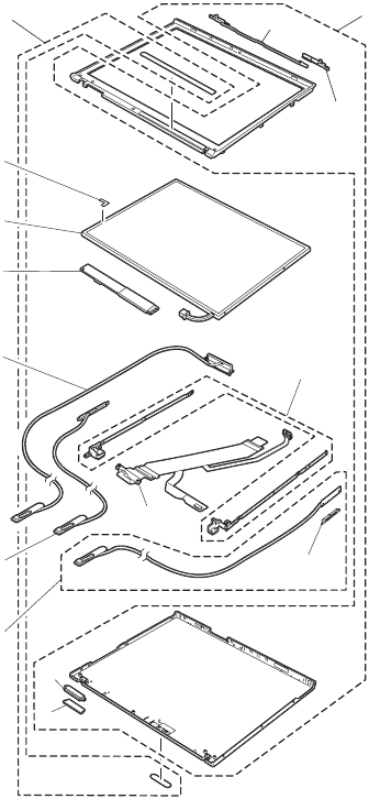
14.1-in. LCD FRUs
1
b
a
2
6
c
d
e
3
7
8
10
5
4
9
Parts list
220 T40/T40p, T41/T41p, T42/T42p

14.1-in. XGA TFT
No. FRU P/N CRU
ID
a-d See “Miscellaneous parts” on page 243.
1 LCD cover kit (WW)
v 2373-12x except 12K, 14x except 14K,
16x, 19x, 1Bx, 22x, 24x, 25x, 2Ax,
2Bx except 2BK, 2Cx, 42x, 44x, 47x,
49x, 4Ax, 4Bx, 4Cx, 51x, 54x, 61x,
66x, 6Bx except 6BK, 6Dx, 71x, 72x
except 72K, 75x except 75K, 76x, 78x,
7Ax, 7Bx, 7Cx except 7CK, 81x, 82x
except 82K, 85x, 86x, 88x, 8Ax, 8Cx
except 8CK, 8Dx, A2x, A3x, A4x, A5x,
A6x, A7x, B2x, B5x, BDx, C1x, C3x,
C4x, C7x, C8x, CAx
v 2373-1Ex, 1Fx, 1Hx, 1Lx, 2Ex, 2Fx,
2Qx, 4Fx, 4Gx, 4Hx, 4Nx, 4Px, 4Qx,
4Sx, 5Hx, 5Qx, 6Kx, 6Sx, 7Ex, 7Fx,
7Jx, 7Kx, 7Mx, 7Px, 8Hx, 8Jx, 8Kx,
8Px, 8Rx, 8Sx, AFx, AHx, ALx, BFx,
BJx
v 2373-1Ux, 1Wx, 1Yx, 1Zx, 2Tx, 2Ux,
2Wx, 2Yx, 4Tx, 4Vx, 4Wx, 4Zx, 5Tx,
5Wx, 6Ux, 6Vx, 6Wx, 6Zx, 7Tx, 7Vx,
7Wx, 7Zx, 8Tx, 8Ux, 8Vx, ATx, AVx,
AWx, FTx, FWx, JTx
v 2373-F1x, H1x, H2x, H3x, J1x, J2x,
J3x, J4x, J5x, J6x, J7x, J8x, J9x, JAx,
JCx, JDx, JEx, JFx, K1x, K2x, K3x,
K6x, K7x, K8x, K9x, KAx, KBx, KEx,
KGx, KHx, KLx, KMx, KNx, KPx
v 2374-12x except 12K, 14x except 14K,
2Ax, 2Cx, 44x, 4Cx, 72x except 72K,
75x except 75K, 7Cx except 7CK, 82x
except 82K, 8Cx except 8CK
v 2374-1Fx, 1Hx, 4Hx, 7Fx, 7Jx, 8Rx
v 2374-1Wx, 4Wx, 6Vx, 8Tx
v 2374-J4x, K1x, K2x
v 2375-72x except 72K
v 2376-72x except 72K
v 2378-D1x, D2x
v 2378-DFx, DGx, DHx, DLx, DMx, EFx,
EJx, ELx, EMx
v 2378-5Ux, DTx, DUx, ETx, EUx, FUx
v 2378-R1x, R3x, R4x, RPx, RQx
v 2379-D3x, D4x
v 2379-5Vx, DKx, ERx
v 2379-R1x
13R2569 N
(continued)
Parts list
ThinkPad T40/T40p, T41/T41p, T42/T42p Series 221

No. FRU P/N CRU
ID
1 LCD cover kit (Korea) for T40/T40p
v 2373-12K, 14K, 29K, 2BK, 6BK, 72K,
75K, 7CK, 82K, 8CK
v 2374-12K, 14K, 72K, 7CK, 75K, 82K,
8CK
v 2375-72K
v 2376-72K
13R2570 N
2 Hinges 91P8388 N
3 LCD cable assembly, 14.1-in. XGA
v 2373-12x, 14x, 16x, 19x, 1Bx, 22x,
24x, 25x, 29x, 2Ax, 2Bx, 2Cx, 42x,
44x, 47x, 49x, 4Ax, 4Bx, 4Cx, 51x,
54x, 61x, 66x, 6Bx, 6Dx, 71x, 72x,
75x, 76x, 78x, 7Ax, 7Cx, 81x, 82x,
85x, 86x, 88x, 8Ax, 8Cx, 8Dx, A2x,
A3x, A5x, A6x, A7x, B2x, B5x, BDx,
C1x, C3x, C4x, C7x, C8x, CAx
v 2373-1Ex, 1Fx, 1Hx, 1Lx, 2Ex, 2Fx,
2Qx, 4Fx, 4Gx, 4Hx, 4Nx, 4Px, 4Qx,
4Sx, 5Hx, 6Kx, 6Sx, 7Ex, 7Fx, 7Jx,
7Kx, 7Mx, 7Px, 8HU, 8Jx, 8Kx, 8Px,
8Rx, 8Sx, AFx, AHx, ALx, BFx, BJx
v 2373-1Ux, 1Wx, 1Yx, 1Zx, 2Tx, 2Ux,
2Wx, 2Yx, 4Tx, 4Vx, 4Wx, 4Zx, 5Tx,
5Wx, 6Ux, 6Vx, 6Wx, 6Zx, 7Tx, 7Vx,
7Wx, 7Zx, 8Tx, 8Ux, 8Vx, ATx, AVx,
AWx, FWx, JTx
v 2373-F1x, H1x, H2x, H3x, J1x, J2x,
J3x, J4x, J5x, J6x, J7x, J8x, J9x, JAx,
JCx, JDx, JEx, JFx, K1x, K2x, K3x,
K6x, K7x, K8x, K9x, KAx, KBx, KEx,
KGx, KHx, KLx, KMx, KNx, KPx
v 2374-12x, 14x, 2Ax,2Cx, 44x, 4Cx,
72x, 75x, 7Cx, 82x, 8Cx
v 2374-1Hx, 1Fx, 4Hx, 7Fx, 7Jx, 8Rx
v 2374-1Wx, 4Wx, 6Vx, 8Tx
v 2374-J4x, K1x, K2x
v 2375-72x
v 2376-72x
v 2378-D1U, D2U
v 2378-DFx, DGx, DHx, EFx, EJx, ELx,
EMx
v 2378-5Ux, DTx, DUx, ETx, EUx, FTx,
FUx
v 2378-R1x, R3x, R4x, RPx, RQx
v 2379-D3U, D4U
v 2379-5Vx, DKx, ERx
v 2379-R1x
91P6786 N
(continued)
Parts list
222 T40/T40p, T41/T41p, T42/T42p

No. FRU P/N CRU
ID
4 Wireless AUX antenna 13N5517 N
5 Bluetooth wireless antenna assembly
v 2373-42x, 4Ax, A2x
v 2373-2Fx, 4Fx, 4Gx, 4Px, AFx
v 2373- 4Zx, 6Zx, 7Zx, AWx, FWx
v 2373-F1x, H3x, J1x, JAx, JFx, K1x,
K2x, K9x, KBx, KMx, KNx, KPx
v 2374-K1x, K2x,
v 2378-EMx
v 2378-DTx, DUx, ETx, EUx, FTx
v 2378-R1x, R3x, R4x, RPx, RQx
v 2379-R1x
13N5515 N
6 Antenna assembly 13N5517 N
7 Inverter card 26P8464 N
8 LCD panel, 14.1-in. XGA, ID Tech for
T40
v 2373-12x, 14x, 16x, 19x, 1Bx, 22x,
24x, 25x, 29x, 2Ax, 2Bx, 2Cx, 42x,
44x, 47x, 49x, 4Ax, 4Bx, 4Cx, 51x,
54x, 61x, 66x, 6Bx, 6Dx, 71x, 72x,
75x, 76x, 78x, 7Ax, 7Cx, 81x, 82x,
85x, 86x, 88x, 8Ax, 8Cx, 8Dx, A2x,
A3x, A5x, A6x, A7x, B2x, B5x, BDx,
C1x, C3x, C4x, C7x, C8x, CAx
v 2374-12x, 14x, 2Ax,2Cx, 44x, 4Cx,
72x, 75x, 7Cx, 82x, 8Cx
v 2375-72x
v 2376-72x
v 2378-D1U, D2U
v 2379-D3U, D4U
11P8350 N
(continued)
Parts list
ThinkPad T40/T40p, T41/T41p, T42/T42p Series 223

No. FRU P/N CRU
ID
8 LCD panel, 14.1-in. XGA for T40, T41, T42
v 2373-12x, 14x, 16x, 19x, 1Bx, 22x, 24x, 25x, 29x, 2Ax,
2Bx, 2Cx, 42x, 44x, 47x, 49x, 4Ax, 4Bx, 4Cx, 51x, 54x,
61x, 66x, 6Bx, 6Dx, 71x, 72x, 75x, 76x, 78x, 7Ax, 7Cx,
81x, 82x, 85x, 86x, 88x, 8Ax, 8Cx, 8Dx, A2x, A3x, A5x,
A6x, A7x, B2x, B5x, BDx, C1x, C3x, C4x, C7x, C8x, CAx
v 2373-1Ex, 1Fx, 1Hx, 1Lx, 2Ex, 2Fx, 2Qx, 4Fx, 4Gx, 4Hx,
4Nx, 4Px, 4Qx, 4Sx, 5Hx, 6Kx, 6Sx, 7Ex, 7Fx, 7Jx, 7Kx,
7Mx, 7Px, 8HU, 8Jx, 8Kx, 8Px, 8Rx, 8Sx, AFx, AHx, ALx,
BFx, BJx
v 2373-1Ux, 1Wx, 1Yx, 1Zx, 2Tx, 2Ux, 2Wx, 2Yx, 4Tx,
4Vx, 4Wx, 4Zx, 5Tx, 5Wx, 6Ux, 6Vx, 6Wx, 6Zx, 7Tx,
7Vx, 7Wx, 7Zx, 8Tx, 8Ux, 8Vx, ATx, AVx, AWx, FWx, JTx
v 2373-F1x, H1x, H2x, H3x, J1x, J2x, J3x, J4x, J5x, J6x,
J7x, J8x, J9x, JAx, JCx, JDx, JEx, JFx, K1x, K2x, K3x,
K6x, K7x, K8x, K9x, KAx, KBx, KEx, KGx, KHx, KLx,
KMx, KNx, KPx
v 2374-12x, 14x, 2Ax, 2Cx, 44x, 4Cx, 72x, 75x, 7Cx, 82x,
8Cx
v 2374-1Hx, 1Fx, 4Hx, 7Fx, 7Jx, 8Rx
v 2374-1Wx, 4Wx, 6Vx, 8Tx
v 2374-J4x, K1x, K2x
v 2375-72x
v 2376-72x
v 2378-D1U, D2U
v 2378-DFx, DGx, DHx, EFx, EJx, ELx, EMx
v 2378-5Ux, DTx, DUx, ETx, EUx, FTx, FUx
v 2378-R1x, R3x, R4x, RPx, RQx
v 2379-D3U, D4U
v 2379-5Vx, DKx, ERx
v 2379-R1x
Samsung 11P8352 N
LG 92P6726 N
(continued)
Parts list
224 T40/T40p, T41/T41p, T42/T42p

No. FRU P/N CRU
ID
8 LCD panel, 14.1-in. XGA, CMO for T41,
T42
v 2373-1Ex, 1Fx, 1Hx, 1Lx, 2Ex, 2Fx,
2Qx, 4Fx, 4Gx, 4Hx, 4Nx, 4Px, 4Qx,
4Sx, 5Hx, 6Kx, 6Sx, 7Ex, 7Fx, 7Jx,
7Kx, 7Mx, 7Px, 8HU, 8Jx, 8Kx, 8Px,
8Rx, 8Sx, AFx, AHx, ALx, BFx, BJx
v 2373-1Ux, 1Wx, 1Yx, 1Zx, 2Tx, 2Ux,
2Wx, 2Yx, 4Tx, 4Vx, 4Wx, 4Zx, 5Tx,
5Wx, 6Ux, 6Vx, 6Wx, 6Zx, 7Tx, 7Vx,
7Wx, 7Zx, 8Tx, 8Ux, 8Vx, ATx, AVx,
AWx, FWx, JTx
v 2373-F1x, H1x, H2x, H3x, J1x, J2x,
J3x, J4x, J5x, J6x, J7x, J8x, J9x, JAx,
JCx, JDx, JEx, JFx, K1x, K2x, K3x,
K6x, K7x, K8x, K9x, KAx, KBx, KEx,
KGx, KHx, KLx, KMx, KNx, KPx
v 2374-12x, 14x, 2Ax,2Cx, 44x, 4Cx,
72x, 75x, 7Cx, 82x, 8Cx
v 2374-1Wx, 4Wx, 6Vx, 8Tx
v 2374-J4x, K1x, K2x
v 2378-DFx, DGx, DHx, EFx, EJx, ELx,
EMx
v 2378-5Ux, DTx, DUx, ETx, EUx, FTx,
FUx
v 2378-R1x, R3x, R4x, RPx, RQx
v 2379-5Vx, DKx, ERx
v 2379-R1x
92P6675 N
9 Tape on Bluetooth wireless antenna
v 2373-42x, 4Ax, A2x
v 2373-2Fx, 4Fx, 4Gx, 4Px, AFx
v 2373- 4Zx, 6Zx, 7Zx, AWx, FWx
v 2373-F1x, H3x, J1x, JAx, JFx, K1x,
K2x, K9x, KBx, KMx, KNx, KPx
v 2374-K1x, K2x,
v 2378-EMx
v 2378-DTx, DUx, ETx, EUx, FTx
v 2378-R1x, R3x, R4x, RPx, RQx
v 2379-R1x
13N5105 N
10 Clear plate 13R2455 N
Parts list
ThinkPad T40/T40p, T41/T41p, T42/T42p Series 225

14.1-in. SXGA+ TFT
No. FRU P/N CRU
ID
a-d See “Miscellaneous parts” on page 243.
1 LCD cover kit (WW)
v 2373-32x, 33x, 58x, 91x, 92x, 93x,
94x except 94K, 96x, 9Ax, 9Bx, 9Cx,
A1x, A8x, A9x, G1x except G1K, G2x
v 2373-3Fx, 3Hx, 3Px, 5Qx, 5Rx, 9Ex,
9Fx, 9Gx, 9Hx, 9Jx, 9Kx, AEx, AJx,
AKx, AMx, ANx, BHx, GEx, GGx, GHx,
GJx, GKx, GLx, GMx
v 2373-3Ux, 3Vx, 3Wx, 3Zx, 4Ux, 5Xx,
8Xx, 8Zx, 9Tx, 9Ux, 9Vx, 9Xx, 9Zx,
BTx, BVx, BXx, BYx, BZx, GRx, GSx,
GTx, GUx, GVx, GXx, GYx, GZx, KYx,
KUx
v 2373-H4x, H5x, H6x, H7x, K5x, KCx,
KDx, KFx, KJx, KQx, Mxx, Pxx
v 2374-9Cx
v 2374-3Hx, GGx
v 2374-3Vx
v 2374-K5x
v 2378-DEx, EEx, ENx, EPx
v 2378-EVx, FVx
v 2378-R5x, RRx
v 2379-D5x, D6x
v 2379-DJx, ESx
v 2379-R5x
13R2569 N
LCD cover kit (Korea) for T40/T40p
v 2373-94K, G1K
13R2570 N
2 Hinges 91P8388 N
Parts list
226 T40/T40p, T41/T41p, T42/T42p

No. FRU P/N CRU
ID
3 LCD cable assembly, 14.1-in. SXGA+
v 2373-32x, 33x, 3Cx, 58x, 91x, 92x,
93x, 94x, 96x, 9Cx, A1x, A8x, A9x,
G1x, G2x, G3x, G4x, G5x, G6x
v 2373-3Fx, 3Hx, 3Px, 5Qx, 5Rx, 9Ex,
9Fx, 9Gx, 9Jx, 9Hx, 9Kx, AEx, AJx,
AKx, AMx, BHx, ANx, GEx, GGx, GHx,
GJx, GKx, GLx, GMx
v 2373-3Ux, 3Vx, 3Wx, 3Zx, 4Ux, 5Xx,
8Xx, 8Zx, 9Tx, 9Ux, 9Vx, 9Xx, 9Zx,
BTx, BVx, BXx, BYx, BZx, GRx, GSx,
GTx, GUx, GVx, GXx, GYx, GZx, KTx,
KUx
v 2373-H4x, H5x, H6x, H7x, K5x, KCx,
KDx, KFx, KJx, KQx, Mxx, Pxx
v 2374-9Cx
v 2374-3Hx, GGx
v 2374-3Vx
v 2374-K5x
v 2378-DEx, EEx, EKx, ENx, EPx
v 2378-EVx, FVx
v 2378-R5x, RRx
v 2379-D5U, D6U
v 2379-DJx, ESx
v 2379-R5x
91P6787 N
4 Wireless AUX antenna 13N5517 N
(continued)
Parts list
ThinkPad T40/T40p, T41/T41p, T42/T42p Series 227

No. FRU P/N CRU
ID
5 Bluetooth wireless antenna assembly
v 2373-32x, 33x, 3Cx, 42x, 4Ax, 58x,
91x, 92x, 93x, 94x, 96x, 9Cx, A1x,
A8x, A9x, G1x, G2x, G3x, G4x, G5x,
G6x
v 2373-3Fx, 3Hx, 3Px, 5Qx, 5Rx, 9Ex,
9Fx, 9Gx, 9Jx, 9Hx, 9Kx, AEx, AJx,
AKx, AMx, BHx, ANx, GEx, GGx, GHx,
GJx, GKx, GLx, GMx
v 2373-3Ux, 3Zx, 9Ux, 9Vx, 9Wx, 9Yx,
BTx, BVx, BXx, BYx, BZx, GRx, GSx,
GTx, GVx, GXx, GYx, GZx, GWx,
KTx, KUx
v 2373-H4x, H5x, H6x, H7x, K5x, KCx,
KDx, KFx, KJx, KQx, Mxx, Pxx
v 2374-9Cx
v 2374-3Hx, GGx
v 2374-8Wx, 9Wx, GTx
v 2374-K5x
v 2378-DEx, EEx, EKx, ENx, EPx
v 2378-EVx, FVx
v 2378-R5x, RRx
v 2379-D5U, D6U
v 2379-DJx, ESx
v 2379-R5x
13N5515 N
6 Antenna assembly 13N5517 N
7 Tape on Bluetooth wireless antenna
v 2373-32x, 33x, 3Cx, 42x, 4Ax, 58x,
91x, 92x, 93x, 94x, 96x, 9Cx, A1x,
A8x, A9x, G1x, G2x, G3x, G4x, G5x,
G6x
v 2373-3Fx, 3Hx, 3Px, 5Qx, 5Rx, 9Ex,
9Fx, 9Gx, 9Jx, 9Hx, 9Kx, AEx, AJx,
AKx, AMx, BHx, ANx, GEx, GGx, GHx,
GJx, GKx, GLx, GMx
v 2373-3Ux, 3Zx, 9Ux, 9Vx, 9Wx, 9Yx,
BTx, BVx, BXx, BYx, BZx, GRx, GSx,
GTx, GVx, GXx, GYx, GZx, GWx,
KTx, KUx
v 2373-H4x, H5x, H6x, H7x, K5x, KCx,
KDx, KFx, KJx, KQx, Mxx, Pxx
v 2374-9Cx
v 2374-3Hx, GGx
v 2374-8Wx, 9Wx, GTx
v 2378-DEx, EEx, EKx, ENx, EPx
v 2378-EVx, FVx
v 2378-R5x, RRx
v 2379-D5U, D6U
v 2379-DJx, ESx
v 2379-R5x
13N5105 N
8 Inverter card 26P8464 N
(continued)
Parts list
228 T40/T40p, T41/T41p, T42/T42p

No. FRU P/N CRU
ID
9 LCD panel, 14.1-in. SXGA+ for T40/T40p, T41/T41p,
T42/T42p
v 2373-32x, 33x, 3Cx, 58x, 91x, 92x, 93x, 94x, 96x, 9Cx,
A1x, A8x, A9x, G1x, G2x, G3x, G4x, G5x, G6x
v 2373-3Fx, 3Hx, 3Px, 5Qx, 5Rx, 9Ex, 9Fx, 9Gx, 9Jx, 9Hx,
9Kx, AEx, AJx, AKx, AMx, BHx, ANx, GEx, GGx, GHx,
GJx, GKx, GLx, GMx
v 2373-3Ux, 3Vx, 3Wx, 3Zx, 4Ux, 5Xx, 8Wx, 8Zx, 9Tx,
9Ux, 9Vx, 9Wx, 9Yx, BTx, BVx, BXx, BYx, BZx, GRx,
GSx, GTx, GVx, GWx, GXx, GYx, GZx, KTx, KUx
v 2373-H4x, H5x, H6x, H7x, K5x, KCx, KDx, KFx, KJx,
KQx, Mxx, Pxx
v 2374-9Cx
v 2374-3Hx, GGx
v 2374-3Vx
v 2374-K5x
v 2378-DEx, EEx, EKx, ENx, EPx
v 2378-EVx, FVx
v 2378-R5x, RRx
v 2379-D5U, D6U
v 2379-DJx, ESx
v 2379-R5x
ID Tech 11P8346 N
Samsung 11P8348 N
10 Clear plate 13R2455 N
Parts list
ThinkPad T40/T40p, T41/T41p, T42/T42p Series 229
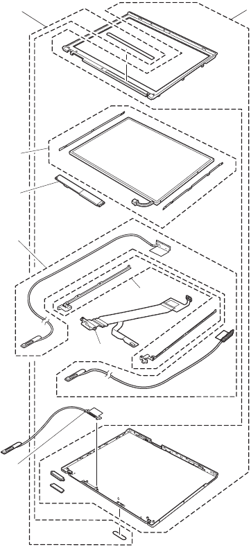
15.0-in. LCD FRUs
1
2
5
3
6
7
8
4
Parts list
230 T40/T40p, T41/T41p, T42/T42p

15.0-in. XGA TFT
No. FRU P/N CRU
ID
1 LCD cover kit, 15.0-in. (WW)
v 2373-4Yx, 6Yx, 7Yx, AUx, FYx
v 2373-F2x, F3x, F5x, H8x, JBx, L1x,
L2x
v 2374-6Yx
v 2374-L1x, F2x, F3x, F5x
v 2378-2Zx, DVx, DWx, EWx, FZx
v 2378-R6x, R7x, R8x, RSx
v 2379-DZx
v 2379-R6x, R8x
13R2917 N
2 Hinges, 15.0-in. 13R2918 N
3 LCD cable assembly, 15.0-in. XGA
v 2373-4Yx, 6Yx, 7Yx, AUx, FYx
v 2373-F2x, F3x, F5x, H8x, JBx, L1x,
L2x
v 2374-6Yx
v 2374-L1x, F2x, F3x, F5x
v 2378-2Zx, DVx, DWx, EWx, FZx
v 2378-R6x, R7x, R8x, RSx
v 2379-DZx
v 2379-R6x, R8x
91P6856 N
4 Bluetooth wireless antenna, 15.0-in.
v 2373-F2x, F3x, F5x, JBx, L1x
v 2374-L1x
91P6860 N
5 Antenna, 15.0-in. 91P6859 N
6 Inverter card, TN
v 2373-4Yx, 6Yx, 7Yx, AUx, FYx
v 2373-F2x, F3x, F5x, H8x, JBx, L1x,
L2x
v 2374-6Yx
v 2374-L1x, F2x, F3x, F5x
v 2378-2Zx, DVx, DWx, EWx, FZx
v 2378-R6x, R7x, R8x, RSx
v 2379-DZx
v 2379-R6x, R8x
91P7422 N
7 LCD panel, 15.0-in. XGA
v 2373-4Yx, 6Yx, 7Yx, AUx, FYx
v 2373-F2x, F3x, F5x, H8x, JBx, L1x, L2x
v 2374-6Yx
v 2374-L1x, F2x, F3x, F5x
v 2378-2Zx, DVx, DWx, EWx, FZx
v 2378-R6x, R7x, R8x, RSx
v 2379-DZx
v 2379-R6x, R8x
Samsung 92P6701 N
LG 92P6699 N
8 Clear plate 13R2455 N
Parts list
ThinkPad T40/T40p, T41/T41p, T42/T42p Series 231

15.0-in. SXGA+ IPS TFT
No. FRU P/N CRU
ID
1 LCD cover kit, 15.0-in. (WW)
v 2373-3Xx, 3Yx, 8Yx, AYx, BUx, CUx,
Cvx, CWx, CXx, CYx, JXx
v 2373-H9x, HAx, KKx, L3x, L4x, L5x,
L6x, L7x, L8x, Nxx
v 2374-3Xx
v 2378-DXx, EXx, EYx
v 2378-RTx, RUx
v 2379-DXx, EYx
v 2379-RUx
13R2917 N
2 Hinges, 15.0-in. 13R2918 N
3 LCD cable assembly, 15.0-in. SXGA+
v 2373-3Xx, 3Yx, 8Yx, AYx, BUx, CUx,
Cvx, CWx, CXx, CYx, JXx
v 2373-H9x, HAx, KKx, L3x, L4x, L5x,
L6x, L7x, L8x, Nxx
v 2374-3Xx
v 2378-DXx, EXx, EYx
v 2378-RTx, RUx
v 2379-DXx, EYx
v 2379-RUx
91P6857 N
4 Bluetooth wireless antenna, 15.0-in.
v 2373-3Xx, 3Yx, 8Yx, AYx, BUx, CUx,
Cvx, CWx, CXx, CYx, JXx
v 2373-H9x, HAx, KKx, L3x, L4x, L5x,
L6x, L7x, L8x, Nxx
v 2374-3Xx
v 2378-DXx, EXx, EYx
v 2378-RTx, RUx
v 2379-DXx, EYx
v 2379-RUx
91P6860 N
5 Antenna, 15.0-in. 91P6859 N
6 Inverter card, IPS
v 2373-3Xx, 3Yx, 8Yx, AYx, BUx, CUx,
Cvx, CWx, CXx, CYx, JXx
v 2373-H9x, HAx, KKx, L3x, L4x, L5x,
L6x, L7x, L8x, Nxx
v 2374-3Xx
v 2378-DXx, EXx, EYx
v 2378-RTx, RUx
v 2379-DXx, EYx
v 2379-RUx
93P4161 N
(continued)
Parts list
232 T40/T40p, T41/T41p, T42/T42p

No. FRU P/N CRU
ID
7 LCD panel, 15.0 SXGA+ (ID Tech)
v 2373-3Xx, 3Yx, 8Yx, AYx, BUx, CUx,
Cvx, CWx, CXx, CYx, JXx
v 2373-H9x, HAx, KKx, L3x, L4x, L5x,
L6x, L7x, L8x, Nxx
v 2374-3Xx
v 2378-DXx, EXx, EYx
v 2378-RTx, RUx
v 2379-DXx, EYx
v 2379-RUx
92P6680 N
8 Clear plate 13R2455 N
Parts list
ThinkPad T40/T40p, T41/T41p, T42/T42p Series 233

15.0-in. UXGA IPS TFT
No. FRU P/N CRU
ID
a-d See “Miscellaneous parts” on page 243.
1 LCD cover kit, 15.0-in. (WW)
v 2373-AZx, HTx, HVx, HWx, HXx, HYx,
KXx, KYx, KZx
v 2373-F4x, HBx, Qxx
v 2374-7Xx, HTx
v 2374-Q2x
v 2378-DYx, EZx
v 2378-RVx
v 2379-DYx, EZx
v 2379-RVx
13R2917 N
2 Hinges, 15.0-in. 13R2918 N
3 LCD cable assembly 15.0 UXGA
v 2373-AZx, HTx, HVx, HWx, HXx, HYx,
KXx, KYx, KZx
v 2373-F4x, HBx, Qxx
v 2374-7Xx, HTx
v 2374-Q2x
v 2378-DYx, EZx
v 2378-RVx
v 2379-DYx, EZx
v 2379-RVx
91P6858 N
4 Bluetooth wireless antenna, 15.0-in.
v 2373-AZx, HTx, HVx, HWx, HXx, HYx,
KXx, KYx, KZx
v 2373-F4x, HBx, Qxx
v 2374-7Xx, HTx
v 2374-Q2x
v 2378-DYx, EZx
v 2378-RVx
v 2379-DYx, EZx
v 2379-RVx
91P6860 N
5 Antenna, 15.0-in. 91P6859 N
6 Inverter card, IPS
v 2373-AZx, HTx, HVx, HWx, HXx, HYx,
KXx, KYx, KZx
v 2374-7Xx, HTx
v 2378-DYx, EZx
v 2379-DYx, EZx
93P4161 N
7 LCD panel, 15.0 UXGA (ID Tech)
v 2373-AZx, HTx, HVx, HWx, HXx, HYx,
KXx, KYx, KZx
v 2373-F4x, HBx, Qxx
v 2374-7Xx, HTx
v 2374-Q2x
v 2378-DYx, EZx
v 2378-RVx
v 2379-DYx, EZx
v 2379-RVx
92P6683 N
8 Clear plate 13R2455 N
Parts list
234 T40/T40p, T41/T41p, T42/T42p

Keyboard
Table 1. Keyboards for 15.0-in. LCD models
Language P/N
(NMB)
P/N
(ALPS)
P/N
(CHICONY)
CRU
ID
Arabic 93P4801 93P4861 13N9914 **
Belgian 93P4796 93P4856 13N9909
Chinese,
Traditional
93P4798 93P4858 13N9911
Czech 93P4802 93P4862 13N9915
Danish 93P4789 93P4849 13N9902
Dutch 93P4786 93P4846 13N9899
English, U.K. 93P4782 93P4842 13N9895
English, U.S. 93P4780 93P4840 13N9893
English, U.S.
(International)
91P9248 — 13N9922
French, Canadian 93P4783 93P4843 13N9896
French, Canadian
(058)
93P4809 93P4869 13N9923
French, European 93P4785 93P4845 13N9898
German 93P4784 93P4844 13N9897
Greek 93P4804 93P4864 13N9917
Hungarian 93P4803 93P4863 13N9916
Hebrew 93P4800 93P4860 13N9913
Italian 93P4790 93P4850 13N9903
Japanese 93P4781 93P4841 13N9894
Korean 93P4795 93P4855 13N9908
Norwegian 93P4788 93P4848 13N9901
Polish 93P4806 93P4866 13N9919
Portuguese 93P4793 93P4853 13N9906
Russian 93P4799 93P4859 13N9912
Slovak 93P4805 93P4865 13N9918
Slovenian 93P4807 93P4867 13N9920
Spanish, European 93P4791 93P4851 13N9904
Spanish, Latin
American
93P4794 93P4854 13N9907
Swedish or Finnish 93P4787 93P4847 13N9900
Swiss 93P4792 93P4852 13N9905
Thai 93P4808 93P4868 13N9921
Turkish 93P4797 93P4857 13N9910
Parts list
ThinkPad T40/T40p, T41/T41p, T42/T42p Series 235

Table 2. Keyboards for 14.1-in. LCD models
Language P/N
(NMB)
P/N
(CHICONY)
CRU
ID
Arabic 08K5065 13N9852 **
Belgian 08K5060 13N9847
Chinese, Traditional 08K5062 13N9849
Czech 08K5066 13N9853
Danish 08K5053 13N9840
Dutch 08K5050 13N9837
English, U.K. 08K5046 13N9833
English, U.S. 08K5044 13N9831
English, U.S. (International) 93P4719 13N9860
French, Canadian 08K5047 13N9834
French, Canadian (058) 93P4744 13N9861
French, European 08K5049 13N9836
German 08K5048 13N9835
Greek 08K5068 13N9855
Hungarian 08K5067 13N9854
Hebrew 93P4711 13N9851
Italian 08K5054 13N9841
Japanese 08K5045 13N9832
Korean 08K5059 13N9846
Norwegian 08K5052 13N9839
Polish 08K5070 13N9857
Portuguese 08K5057 13N9844
Russian 08K5063 13N9850
Slovak 08K5069 13N9856
Slovenian 08K5071 13N9858
Spanish, European 08K5055 13N9842
Spanish, Latin American 08K5058 13N9845
Swedish or Finnish 08K5051 13N9838
Swiss 08K5056 13N9843
Thai 08K5072 13N9859
Turkish 08K5061 13N9848
Parts list
236 T40/T40p, T41/T41p, T42/T42p

Recovery CDs
Windows XP Professional (for T40/T40p
series)
Windows XP Professional is preinstalled as the operating
system in the following models:
v 2373-12x, 14x, 19x, 1Bx, 22x, 24x, 29x, 2Ax, 2Bx, 2Cx,
32x, 33x, 3Cx, 42x, 44x, 47x, 49x, 4Ax, 4Bx, 4Cx, 51x,
54x, 58x, 61x, 6Bx, 71x, 72x, 75x, 76x, 78x, 7Ax, 7Cx,
81x, 82x, 85x, 86x, 88x, 8Ax, 8Cx, 8Dx, 91x, 92x, 94x,
96x, 9Cx, C3x, C4x, C7x, C8x, CAx, G1x, G2x, G3x,
G4x, G5x, G6x
v 2374-12x, 14x, 72x, 75x, 7Cx, 82x, 8Cx
v 2375-72x
v 2376-72x
v 2378-D1U, D2U
v 2379-D3U, D4U, D5U, D6U
Language P/N CRU
ID
Arabic 01R8058 *
Chinese, Simplified 01R8253
Chinese, Traditional 01R8252
Chinese, Traditional (Hong Kong S.A.R.) 01R8254
Czech 01R8059
Danish 01R8049
Dutch 01R8056
English, U.K. 01R8047
English, U.S. 01R8046
Finnish 01R8055
French 01R8050
German 01R8051
Greek 01R8063
Hebrew 01R8060
Hungarian 01R8064
Italian 01R8054
Japanese 01R8255
Norwegian 01R8057
Polish 01R8061
Portuguese 01R8048
Russian 01R8065
Spanish 01R8052
Swedish 01R8053
Turkish 01R8062
Parts list
ThinkPad T40/T40p, T41/T41p, T42/T42p Series 237

Windows XP Professional (for T41/T41p
series)
Windows XP Professional is preinstalled as the operating
system in the following models:
v 2373-1Ex, 1Fx, 1Hx, 1Lx, 2Ex, 2Fx, 2Qx, 2Rx, 3Fx,
3Hx, 3Px, 4Fx, 4Gx, 4Hx, 4Nx, 4Px, 4Qx, 4Sx, 5Hx,
5Qx, 7Ex, 7Fx, 7Jx, 7Kx, 7Mx, 7Px, 8Hx, 8Jx, 8Kx, 8Px,
8Rx, 8Sx, 9Ex, 9Fx, 9Hx, 9Jx, 9Kx, 9Px, 9Rx, GEx,
GGx, GHx, GJx, GKx, GLx, GMx
v 2374-1Hx, 1Fx, 3Hx, 7Fx, 7Jx, 8Rx, GGx
v 2378-DEx, DFx, DGx, DHx
v 2379-DJx, DKx
Language P/N CRU
ID
Arabic 24R4557 *
Chinese, Simplified 24R4550
Chinese, Traditional 24R4551
Chinese, Traditional (Hong Kong S.A.R.) 24R4552
Czech 24R4556
Danish 24R4546
Dutch 24R4549
English, U.K. 24R4539
English, U.S. 24R4538
Finnish 24R4547
French 24R4540
German 24R4541
Greek 24R4561
Hebrew 24R4554
Hungarian 24R4560
Italian 24R4543
Japanese 24R4553
Norwegian 24R4548
Polish 24R4555
Portuguese, Brazilian 24R4544
Russian 24R4558
Spanish 24R4542
Swedish 24R4545
Turkish 24R4559
Parts list
238 T40/T40p, T41/T41p, T42/T42p
Windows XP Professional (for T42/T42p
series)
Windows XP Professional is preinstalled as the operating
system in the following models:
v 2373-1Ux, 1Wx, 1Yx, 1Zx, 2Tx, 2Ux, 2Wx, 2Xx, 2Yx,
3Ux, 3Vx, 3Wx, 3Xx, 3Yx, 3Zx, 4Tx, 4Ux, 4Vx, 4Wx,
4Xx, 4Yx, 4Zx, 5Tx, 5Xx, 5Wx, 6Ux, 6Vx, 6Wx, 6Yx,
6Zx, 7Tx, 7Vx, 7Wx, 7Xx, 7Yx, 7Zx, 8Tx, 8Ux, 8Vx, 8Xx,
8Yx, 8Zx, 9Tx, 9Ux, 9Vx, 9Xx, 9Zx, CUx, CVx, CWx,
CXx, CYx, FWx, FYx, GRx, GSx, GTx, GUx, GVx, GXx,
GYx, GZx, HTx, HVx, HWx, HXx, HYx, JTx, JXx
v 2373-F1x, F2x, F3x, F4x, F5x, J1x, J2x, J3x, J4x, J5x,
J6x, J7x, J8x, J9x, JAx, JBx, JCx, JEx, JFx, Kxx, Lxx,
Mxx, Nxx, Pxx, Qxx
v 2374-1Wx, 3Vx, 3Xx, 4Wx, 6Vx, 6Yx, 7Xx, 8Tx, 8Wx,
9Wx, GTx, HTx
v 2374-J4x, Kxx, L1x, Q2x,
v 2378-2Xx, 5Ux, DTx, DUx, DVx, DWx, DXx, DYx, FUx,
FZx
v 2378-R1x, R2x, R3x, R4x, R5x, R6x, R7x, R8x, R9x
v 2379-5Vx, DWx, DXx, DYx
v 2379-R1x, R5x, R6x, R8x, R9x
Parts list
ThinkPad T40/T40p, T41/T41p, T42/T42p Series 239

Language P/N CRU
ID
Arabic 24R7703 *
Chinese, Simplified 24R7696
Chinese, Traditional 24R7697
Chinese, Traditional (Hong Kong S.A.R.) 24R7698
Czech 24R7702
Danish 24R7692
Dutch 24R7695
English, Russia 39K9693
English, U.K. 24R7685
English, U.S. 24R7684
Finnish 24R7693
French 24R7686
German 24R7687
Greek 24R7707
Hebrew 24R7700
Hungarian 24R7706
Italian 24R7689
Japanese 24R7699
Korean 24R7708
Norwegian 24R7694
Polish 24R7701
Portuguese, Brazilian 24R7690
Russian 39K9625
Spanish 24R7688
Swedish 24R7691
Turkish 24R7705
Parts list
240 T40/T40p, T41/T41p, T42/T42p

Windows 2000 (for T40/T40p series)
Windows 2000 is preinstalled as the operating system in
the following models:
v 2373-16x, 25x, 66x, 6Dx, 93x, B2x, B5x, BDx, C1x
Language P/N CRU
ID
Arabic 01R8158 *
Chinese, Simplified 01R8249
Chinese, Traditional 01R8248
Chinese, Traditional (Hong Kong S.A.R.) 01R8250
Czech 01R8159
Danish 01R8149
Dutch 01R8156
English, U.K. 01R8147
English, U.S. 01R8146
Finnish 01R8155
French 01R8150
German 01R8151
Greek 01R8163
Hebrew 01R8160
Hungarian 01R8164
Italian 01R8154
Japanese 01R8251
Norwegian 01R8157
Polish 01R8161
Portuguese 01R8148
Russian 01R8165
Spanish 01R8152
Swedish 01R8153
Turkish 01R8162
Parts list
ThinkPad T40/T40p, T41/T41p, T42/T42p Series 241

Windows 2000 (for T41 series)
Windows 2000 is preinstalled as the operating system in
the following models:
v 2373-5RJ, 6KJ, 6SJ, 9GJ, BFJ, BJJ, BHJ
Language P/N CRU
ID
Japanese 24R4826 *
Windows XP Home Edition (for T42/T42p
series)
Windows XP Home Edition is preinstalled as the operating
system in the following models:
v 2373-JDx
Language P/N CRU
ID
Arabic 24R6811 *
Chinese, Simplified 24R6804
Chinese, Traditional 24R6805
Chinese, Traditional (Hong Kong S.A.R.) 24R6806
Czech 24R6810
Danish 24R6800
Dutch 24R6803
English, U.K. 24R6793
English, U.S. 24R6792
Finnish 24R6801
French 24R6794
German 24R6795
Greek 24R6815
Hebrew 24R6808
Hungarian 24R6814
Italian 24R6797
Japanese 24R6807
Norwegian 24R6802
Polish 24R6809
Portuguese, Brazilian 24R6798
Russian 24R6812
Spanish 24R6796
Swedish 24R6799
Turkish 24R6813
Parts list
242 T40/T40p, T41/T41p, T42/T42p

Miscellaneous parts
FRU P/N CRU
ID
Screw kit (including nylon-coated screws):
v M2 × 2.7 mm (silver), small head (10)
v M2 × 3 mm (silver), small head (20)
v M2 × 3 mm (from outside), pan head (10)
v M2 × 4 mm (black), bind head (30)
v M2 × 4 mm (black), small head (10)
v M2 × 5 mm (gold), bind head (2)
v M2 × 5 mm (black), flat head (20)
v M2 × 10 mm (black), flat head (30)
v M2 × 12 mm (black), flat head (5)
v M2 × 14 mm (black), bind head (10)
v M2 × 14 mm (black), TR7 (5)
v M2 × 14.9 mm for drive bay (5)
v M2 × 19 mm (black), bind head (5)
v M2.5 × 3 mm (gold), flat head (5)
v M2.5 × 4.8 mm (black), bind head (10)
v M3 × 3 mm (PHILLIPS/slotted) (2)
v Hex stud (5)
v Security screw (1)
v Screw caps (square, thin)
v Screw caps (oval, not painted)
v Screw caps (not painted)
v Screw caps (square)
v Tape on Bluetooth wireless antenna
13R2916 N
Base miscellaneous parts (14.1-in. LCD
models):
v Cover, PC Card slot
v Spacer, PC Card slot
v Spring, PC Card slot cover
v Rubber foot (rear)
v Rubber foot (front)
v Insulation sheet
v Battery lock knob L
v Battery lock latch L
v Battery lock knob R
v Battery lock latch R
v Spring, battery lock
v Slide lever
v Slide lever spring
v Pull lever
v Pull lever spring
v Puller
v Rubber, shock absorber
v Insulation, bottom
v Foam under fan
v Cu tape under fan
v Cu tape
v Insulation, louver
v Screw caps (square, thin)
13N5104 N
(continued)
Parts list
ThinkPad T40/T40p, T41/T41p, T42/T42p Series 243

FRU P/N CRU
ID
Base miscellaneous parts (15.0-in. LCD
models):
v Cover, PC Card slot
v Spring, PC Card slot cover
v Rubber foot (rear)
v Rubber foot (front)
v Battery lock knob L
v Battery lock latch L
v Battery lock knob R
v Link, battery lock
v Spring, battery lock
v Slide lever
v Slide lever spring
v Pull lever
v Pull lever spring
v Puller
v Rubber, shock absorber
v Insulation sheet
v Insulation, bottom
v Foam under fan
v Foam under system board, front
v Foam under system board, rear
v Cu plate, video
v Insulation, louver
v Screw caps (square, thin)
13R2914 N
System miscellaneous parts (14.1-in. LCD
models):
v Cable, RJ11-docking connector on system
board
v DC in cable
v (c) Hard disk drive guide rail
v Spacer for DSP connector
v (e) I/O plate bracket
v (f) Support structure
v Harness (left)
v (b) Antenna cable guide
v Bracket holder, LCD cable
v (d) EMI spring, CDC
v Connector bag
v Screw cap (square, thin)
Note: Italicized letters in parentheses are
references to the exploded view on page 191.
91P8681 N
(continued)
Parts list
244 T40/T40p, T41/T41p, T42/T42p

FRU P/N CRU
ID
System miscellaneous parts (15.0-in. LCD
models):
v Cable, RJ11-docking connector on system
board
v DC in cable
v (c) Hard disk drive guide rail
v Sheet for DSP connector
v (e) I/O plate bracket
v (f) Support structure
v Harness (left)
v (b) Antenna cable guide
v Bracket holder, LCD cable
v (d) EMI spring, CDC
v Connector bag
Note: Italicized letters in parentheses are
references to the exploded view on page 191.
13R2915 N
System board miscellaneous parts:
v Insulator, PC Card slot
v Insulator, louver
v Insulator, docking latch
v Insulator, security chip
v Insulator, docking connector
v Insulator, fan
v Insulator, Mg
v S-video gasket
v Form on system board
v Insulator, louver, hard disk drive
v Mic rubber
v Stud, triangle
v Audio connector bracket
v Security chip spacer
v Stud, system board
v Screw cap (square, thin)
13R2913 N
Base, PC Card slot kit for T40/T40p:
v Cover, PC Card slot
v Spacer, PC Card slot
v Spring, PC Card slot cover
13N5345 N
(continued)
Parts list
ThinkPad T40/T40p, T41/T41p, T42/T42p Series 245

FRU P/N CRU
ID
LCD miscellaneous parts (14.1-in. LCD
models):
v Tape, LCD FPC
v Tape on Bluetooth wireless antenna
v (a) LCD latch R
v (b) LCD latch L assembly
v (c) Cable bushing (lower)
v (d) Cable bushing (upper)
v LED lens
v Cable clip
v Spiral tube
v Screw caps (square, thin)
v Screw caps (oval, not painted)
v Screw caps (not painted)
v Screw caps (square)
Note: Italicized letters in parentheses are
references to the exploded view on page 220.
13R2449 N
AC adapters
FRU P/N CRU
ID
3-pin (72W) slim adapter for PFC model (models xxA, xxB, xxC,
xxG, xxH, xxK, xxM, xxV)
ASTEC OP 08K8203 *
DELTA OP 08K8207 *
SANKEN OP 08K8211 *
2-pin (72W) slim adapter for non-PFC model (models xxE, xxF,
xxJ, xxP, xxS, xxU, xxY)
ASTEC OP 08K8205 *
DELTA OP 08K8209 *
SANKEN OP 08K8213 *
Parts list
246 T40/T40p, T41/T41p, T42/T42p

Optional FRUs
FRU P/N CRU
ID
1-GB DDR SDRAM SO-DIMM (PC2100) 10K0035 *
Hard disk drive, 80 GB, 9.5 mm, 4200 rpm,
ThinkPad STD
08K9863 *
Ultrabay Slim hard disk drive adapter 62P4553 *
Ultrabay Slim Li Polymer battery (2nd bay
battery), Sanyo (WW)
08K8191 *
ThinkPad Dock II 67P9010 *
Top cover and screw kit for ThinkPad Dock II 46P3085 **
PCI cover for ThinkPad Dock II 46P3086 *
ThinkPad Mini Dock 67P9011 *
AC adapter (2 pin, 120 W), DELTA for
ThinkPad Mini Dock
02K7086 *
AC adapter (2 pin, 120 W), LITEON for
ThinkPad Mini Dock
02K7092 *
AC adapter (3 pin, 120 W), LITEON for
ThinkPad Mini Dock
02K7094 *
AC adapter (3 pin, 120 W), LITEON for
ThinkPad Mini Dock
02K7096 *
ThinkPad Port Replicator II 74P6735 *
ThinkPad Slim Drive Adapter for Ultrabay
2000
62P4556 *
Multiple battery charger 02K6642 *
Diskette drive cable 27L0525 *
Diskette drive (TEAC) 08K9606 *
Diskette drive (Sony) 08K9607 *
Parts list
ThinkPad T40/T40p, T41/T41p, T42/T42p Series 247

Common parts list
Tools
Tool P/N
Triconnector wrap plug 72X8546
PC test card 35G4703
Audio wrap cable 66G5180
USB parallel test cable 05K2580
Screwdriver kit 95F3598
Mini PC tool set 00P7033
1/4" drive spinner handle 1650840
1/4" Sq. to 1/4" hex torx adapter 93F2838
TR7-TR-10 tamper resistant torx bits 00P6967
Removal tool antenna RF connector 08K7159
USB floppy disk drive for maintenance diskette 05K9283
ThinkPad Hardware Maintenance Diskette Version
1.73 or later
Note: Download the file from the following Web site:
http://www.lenovo.com/think/spm
—
Power cords (system)
A ThinkPad power cord for a specific country or region is
usually available only in that country or region:
For 2-pin power cords:
Region P/N CRU
ID
Canada, U.S. 13H5264 *
Japan 74P4331
Argentina 36L8870
Brazil 49P2095
Parts list
248 T40/T40p, T41/T41p, T42/T42p

For 3-pin power cords:
Region P/N CRU
ID
Australia, New Zealand 76H3514 *
Taiwan, Thailand 76H3516
Italy 76H3530
Denmark 76H3520
U.K., China (Hong Kong S.A.R.) 76H3524
European countries 76H3518
India, South Africa 76H3522
Israel 76H3532
Korea 76H3535
China (P.R.C.) (other than Hong Kong S.A.R.) 02K0539
Switzerland 76H3528
Power cords (ThinkPad Dock II)
A ThinkPad power cord for a specific country or region is
usually available only in that country or region:
For 3-pin power cords:
Region P/N CRU
ID
Argentina 36L8868 *
Australia, New Zealand 75H8988
Brazil 49P2101
Canada, Thailand, U.S. 75H8989
Denmark 75H8992
European countries 75H8990
India, South Africa 75H8993
Israel 75H8999
Italy 75H8998
Japan 75H8996
Korea 76H3536
China (P.R.C.) (other than Hong Kong S.A.R) 02K0540
Switzerland 75H8997
U.K. 75H8994
Parts list
ThinkPad T40/T40p, T41/T41p, T42/T42p Series 249

Notices
Lenovo may not offer the products, services, or features
discussed in this document in all countries. Consult your
local Lenovo representative for information on the products
and services currently available in your area. Any
reference to a Lenovo product, program, or service is not
intended to state or imply that only that Lenovo product,
program, or service may be used. Any functionally
equivalent product, program, or service that does not
infringe any Lenovo intellectual property right may be used
instead. However, it is the user’s responsibility to evaluate
and verify the operation of any other product, program, or
service.
Lenovo may have patents or pending patent applications
covering subject matter described in this document. The
furnishing of this document does not give you any license
to these patents. You can send license inquiries, in writing,
to:
Lenovo (United States), Inc.
500 Park Offices Drive, Hwy. 54
Research Triangle Park, NC 27709
U.S.A.
Attention: Lenovo Director of Licensing
LENOVO GROUP LTD. PROVIDES THIS PUBLICATION
“AS IS” WITHOUT WARRANTY OF ANY KIND, EITHER
EXPRESS OR IMPLIED, INCLUDING, BUT NOT LIMITED
TO, THE IMPLIED WARRANTIES OF
NON-INFRINGEMENT, MERCHANTABILITY OR FITNESS
FOR A PARTICULAR PURPOSE. Some jurisdictions do
not allow disclaimer of express or implied warranties in
certain transactions, therefore, this statement may not
apply to you.
This information could include technical inaccuracies or
typographical errors. Changes are periodically made to the
information herein; these changes will be incorporated in
new editions of the publication. Lenovo may make
improvements and/or changes in the product(s) and/or the
program(s) described in this publication at any time without
notice.
The products described in this document are not intended
for use in implantation or other life support applications
where malfunction may result in injury or death to persons.
The information contained in this document does not affect
or change Lenovo product specifications or warranties.
Nothing in this document shall operate as an express or
implied license or indemnity under the intellectual property
rights of Lenovo or third parties. All information contained
in this document was obtained in specific environments
Notices
250 T40/T40p, T41/T41p, T42/T42p
and is presented as an illustration. The result obtained in
other operating environments may vary.
Lenovo may use or distribute any of the information you
supply in any way it believes appropriate without incurring
any obligation to you.
Any references in this publication to non-Lenovo Web sites
are provided for convenience only and do not in any
manner serve as an endorsement of those Web sites. The
materials at those Web sites are not part of the materials
for this Lenovo product, and use of those Web sites is at
your own risk.
Any performance data contained herein was determined in
a controlled environment. Therefore, the result obtained in
other operating environments may vary significantly. Some
measurements may have been made on development-level
systems and there is no guarantee that these
measurements will be the same on generally available
systems. Furthermore, some measurements may have
been estimated through extrapolation. Actual results may
vary. Users of this document should verify the applicable
data for their specific environment.
Notices
ThinkPad T40/T40p, T41/T41p, T42/T42p Series 251

Trademarks
The following terms are trademarks of Lenovo in the
United States, other countries or both:
Lenovo
Rescue and Recovery
ThinkLight
ThinkPad
ThinkPad Dock II
ThinkPad Mini Dock
ThinkPad Port Replicator
ThinkPad Port Replicator II
TrackPoint
Ultrabay
Ultrabay 2000
Ultrabay Plus
UltraNav
The following terms are trademarks of the International
Business Machines Corporation in the United States, other
countries, or both:
IBM (used under license)
OS/2
Microsoft, Windows, and Windows NT are trademarks of
Microsoft Corporation in the United States, other countries,
or both.
Intel and Pentium are trademarks or registered trademarks
of Intel Corporation or its subsidiaries in the United States
and other countries.
Other company, product, or service names may be the
trademarks or service marks of others.
Trademarks
252 T40/T40p, T41/T41p, T42/T42p
Trademarks
ThinkPad T40/T40p, T41/T41p, T42/T42p Series 253

Part Number: 39T6192
(1P) P/N: 39T6192
