Lenovo Z410Z510Z510Touch Hmm Z410&Z510&Z510 Touch User Manual Hardware Maintenance Idea Pad Z410, Z510 Laptop (ideapad)
2013-09-12
User Manual: Lenovo Lenovo Z410Z510Z510Touch Hmm Hardware Maintenance Manual - IdeaPad Z410, Z510 Z510 Laptop (ideapad) ideapad Z510 Notebook
Open the PDF directly: View PDF ![]() .
.
Page Count: 114 [warning: Documents this large are best viewed by clicking the View PDF Link!]
- About this manual
- Safety information
- Important service information
- General checkout
- Related service information
- Lenovo Z410/Z510/Z510 Touch
- Specifications
- Status indicators
- Function key combinations
- FRU replacement notices
- Removing and replacing an FRU
- 1010 Keyboard
- 1020 Optical drive
- 1030 Base cover
- 1040 Battery pack
- 1050 Hard disk drive
- 1060 PCI Express Mini Card for wireless LAN
- 1070 DIMM
- 1080 Fan assembly and Heat Sink assembly
- 1090 CPU
- 1100 ODD board and LED board (Z510/Z510 Touch)
- 1110 Speakers
- 1120 System board
- 1130 LCD unit
- 1140 Keyboard bezel
- 1150 LCD front bezel/LCD hinge cover
- 1160 LCD panel/LCD module
- 1170 LCD Hinges
- 1180 Integrated camera, LCD cable and antenna assembly
- Locations
- Parts list
- Notices

Lenovo Z410/Z510/
Z510 Touch
Hardware
Maintenance
Manual

Notes:
• Beforeusingthisinformationandtheproductitsupports,besuretoreadthegeneralinformationunder
“Notices”onpage109.
• Thismanualappliestothefollowingmodels:LenovoZ410/Z510/Z510Touch.Theillustrationsusedin
thismanualareforLenovoZ510unlessotherwisestated.
First Edition (August. 2012)
© Copyright Lenovo 2012. All rights reserved.
LIMITED AND RESTRICTED RIGHTS NOTICE: If data or software is delivered pursuant a General
Services Administration “GSA” contract, use, reproduction, or disclosure is subject to restrictions set
forth in Contract No. GS-35F-05925.
© 2012 Lenovo

iii
Contents
About this manual ....................................... iv
Safety information ........................................ 1
General safety ................................................ 2
Electrical safety .............................................. 3
Safety inspection guide .................................. 5
Handling devices that are sensitive to
electrostatic discharge .................................... 6
Grounding requirements ................................. 6
Safety notices: multilingual translations.......... 7
Laser compliance statement......................... 14
Important service information ................... 16
Strategy for replacing FRUs ......................... 16
Strategy for replacing a hard disk drive ............17
Important notice for replacing a
system board ...................................................17
Important information about replacing
RoHS compliant FRUs ................................. 18
General checkout ...................................... 19
What to do rst ............................................. 20
Power system checkout................................ 21
Checking the AC adapter .................................21
Checking operational charging .........................21
Related service information ...................... 23
Restoring the factory contents by using
OneKey Recovery ........................................ 23
Restore of factory default .................................23
Passwords .................................................... 24
Power-on password .......................................... 24
Hard-disk password .......................................... 24
Administrator password ...................................24
Power management ..................................... 25
Screen blank mode ...........................................25
Sleep (standby) mode ......................................25
Lenovo Z410/Z510/Z510 Touch .................. 26
Specications ............................................... 26
Status indicators ........................................... 28
Function key combinations ........................... 30
FRU replacement notices ............................. 31
Screw notices ..................................................31
Removing and replacing an FRU ................. 32
1010 Keyboard .................................................33
1020 Optical drive .............................................37
1030 Base cover ...............................................39
1040 Battery pack .............................................44
1050 Hard disk drive .........................................46
1060 PCI Express Mini Card for
wireless LAN .....................................................48
1070 DIMM .......................................................50
1080 Fan assembly and Heat
Sink assembly...................................................51
1090 CPU .........................................................54
1100 ODD board and LED board
(Z510/Z510 Touch) ...........................................55
1110 Speakers ..................................................57
1120
System board ............................................ 60
1130 LCD unit ................................................... 65
1140
Keyboard bezel ......................................... 68
1150 LCD front bezel/LCD hinge cover ............ 70
1160 LCD panel/LCD module ........................... 72
1170 LCD Hinges ..............................................75
1180 Integrated camera, LCD cable
and antenna assembly ....................................77
Locations ...................................................... 81
Front view and right-side view ..........................81
Bottom and Left-side view ...............................83
Parts list ........................................................ 84
Overall ..............................................................85
LCD FRUs ........................................................93
Keyboard ..........................................................98
Miscellaneous parts ........................................ 104
AC adapters ....................................................105
Screws ............................................................ 105
Power cords ....................................................106
Notices....................................................... 109
Trademarks .................................................110
iv
About this manual
This manual contains service and reference information for the following
Lenovo product:
Lenovo Z410/Z510/Z510 Touch
Use this manual to troubleshoot problems.
The manual is divided into the following sections:
• The common sections provide general information, guidelines, and safety
information required for servicing computers.
• The product-specic section includes service, reference, and product-specic
parts information.
Important:
ThismanualisintendedonlyfortrainedservicerswhoarefamiliarwithLenovo
products.Usethismanualtotroubleshootproblemseffectively.
BeforeservicingaLenovoproduct,makesuretoreadalltheinformationunder
“Safetyinformation”onpage1and“Importantserviceinformation”onpage16.

1
Safety information
Safety information
This chapter presents the following safety information that you need to get
familiar with before you service an Lenovo Z410/Z510/Z510 Touch computer:
• “General safety” on page 2
• “Electrical safety” on page 3
• “Safety inspection guide” on page 5
• “Handling devices that are sensitive to electrostatic discharge” on page 6
• “Grounding requirements” on page 6
• “Safety notices: multilingual translations” on page 7
• “Laser compliance statement” on page 14

2
Z410/Z510/Z510 Touch Hardware Maintenance Manual
General safety
Follow these rules below to ensure general safety:
• Observe a good housekeeping in the area where the machines are put
during and after the maintenance.
• When lifting any heavy object:
1. Make sure that you can stand safely without slipping.
2. Distribute the weight of the object equally between your feet.
3. Use a slow lifting force. Never move suddenly or twist when you attempt
to lift it.
4. Lift it by standing or pushing up with your leg muscles; this action could
avoid the strain from the muscles in your back. Do not attempt to lift any
object that weighs more than 16 kg (35 lb) or that you think is too heavy
for you.
• Do not perform any action that causes hazards to the customer, or that
makes the machine unsafe.
• Before you start the machine, make sure that other service representatives
and the customer are not in a hazardous position.
• Place removed covers and other parts in a safe place, keeping them away
from all personnel, while you are servicing the machine.
• Keep your toolcase away from walk areas so that other people will not trip it
over.
• Do not wear loose clothing that can be trapped in the moving parts of the
machine. Make sure that your sleeves are fastened or rolled up above your
elbows. If your hair is long, fasten it.
• Insert the ends of your necktie or scarf inside clothing or fasten it with the
nonconductive clip, about 8 centimeters (3 inches) from the end.
• Do not wear jewelry, chains, metal-frame eyeglasses, or metal fasteners for
your clothing.
Attention: Metal objects are good electrical conductors.
• Wear safety glasses when you are hammering, drilling, soldering, cutting
wire, attaching springs, using solvents, or working in any other conditions
that may be hazardous to your eyes.
• After service, reinstall all safety shields, guards, labels, and ground wires.
Replace any safety device that is worn or defective.
• Reinstall all covers correctly before returning the machine to the customer.
• Fan louvers on the machine help to prevent the overheating of internal
components. Do not obstruct fan louvers or cover them with labels or
stickers.

3
Safety information
Electrical safety
Observe the following rules when working on electrical equipments.
Important:
Useonlyapprovedtoolsandtestequipments.Somehandtoolshavehandles
coveredwithasoftmaterialthatdoesnotinsulateyouwhenworkingwithlive
electricalcurrents.
Manycustomershaverubberfloormatsneartheirmachinesthatcontainsmall
conductiveberstodecreaseelectrostaticdischarges.Donotusesuchkindofmat
toprotectyourselffromelectricalshock.
• Find the room emergency power-off (EPO) switch, disconnecting the switch
or electrical outlet. If an electrical accident occurs, you can then operate the
switch or unplug the power cord quickly.
• Do not work alone under hazardous conditions or near the equipment that
has hazardous voltages.
• Disconnect all power before:
– Performing a mechanical inspection
– Working near power supplies
– Removing or installing main units
• Before you start to work on the machine, unplug the power cord. If you
cannot unplug it, ask the customer to power-off the wall box that supplies
power to the machine, and to lock the wall box in the off position.
• If you need to work on a machine that has exposed electrical circuits,
observe the following precautions:
– Ensure that another person, familiar with the power-off controls, is near
you.
Attention: Another person must be there to switch off the power, if
necessary.
– Use only one hand when working with powered-on electrical equipment;
keep the other hand in your pocket or behind your back.
Attention: An electrical shock can occur only when there is a complete
circuit. By observing the above rule, you may prevent a current from
passing through your body.
– When using testers, set the controls correctly and use the approved
probe leads and accessories for that tester.
– Stand on suitable rubber mats (obtained locally, if necessary) to insulate
you from grounds such as metal oor strips and machine frames.
Observe the special safety precautions when you work with very high voltages;
instructions for these precautions are in the safety sections of maintenance
information. Be extremely careful when you measure the high voltages.
• Regularly inspect and maintain your electrical hand tools for safe operational
condition.
• Do not use worn or broken tools and testers.
• Never assume that power has been disconnected from a circuit. First, check
it to make sure that it has been powered off.

4
Z410/Z510/Z510 Touch Hardware Maintenance Manual
• Always look carefully for possible hazards in your work area. Examples of
these hazards are moist oors, nongrounded power extension cables, power
surges, and missing safety grounds.
• Do not touch live electrical circuits with the reflective surface of a plastic
dental mirror. The surface is conductive; such touching can cause personal
injury and machine damage.
• Do not service the following parts with the power on when they are removed
from their normal operating places in a machine:
– Power supply units
– Pumps
– Blowers and fans
– Motor generators
and similar units. (This practice ensures correct grounding of the units.)
• If an electrical accident occurs:
– Caution: do not become a victim yourself.
– Switch off the power.
– Send the victim to get medical aid.

5
Safety information
Safety inspection guide
The purpose of this inspection guide is to assist you in identifying potential
unsafe conditions. As each machine was designed and built, required safety
items were installed to protect users and service personnel from injury. This
guide addresses only those items. You should use good judgment to identify
potential safety hazards according to the attachment of non-Lenovo features or
options not covered by this inspection guide.
If any unsafe conditions are present, you must determine how serious the
apparent hazard could be and whether you can continue without rst correcting
the problem.
Consider these conditions and the safety hazards they present:
• Electrical hazards, especially primary power (primary voltage on the frame
can cause serious or fatal electrical shock)
• Explosive hazards, such as a damaged CRT face or a bulging capacitor
• Mechanical hazards, such as loose or missing hardware
To determine whether there are any potential unsafe conditions, use the
following checklist at the beginning of every service task. Begin the checks with
the power off, and the power cord disconnected.
Checklist:
1. Check exterior covers for damage (loose, broken, or sharp edges).
2. Turn off the computer. Disconnect the power cord.
3. Check the power cord for:
a. A third-wire ground connector in good condition. Use a meter to measure
third-wire ground continuity for 0.1 ohm or less between the external
ground pin and the frame ground.
b. The power cord should be the type specied in the parts list.
c. Insulation must not be frayed or worn.
4. Check for cracked or bulging batteries.
5. Remove the cover.
6. Check for any obvious non-Lenovo alterations. Use good judgment as to the
safety of any non-Lenovo alterations.
7. Check inside the unit for any obvious unsafe conditions, such as metal
filings, contamination, water or other liquids, or signs of fire or smoke
damage.
8. Check for worn, frayed, or pinched cables.
9. Check that the power-supply cover fasteners (screws or rivets) have not
been removed or tampered with.
6
Z410/Z510/Z510 Touch Hardware Maintenance Manual
Handling devices that are sensitive to electrostatic discharge
Any computer part containing transistors or integrated circuits (ICs) should be
considered sensitive to electrostatic discharge (ESD). ESD damage can occur
when there is a difference in charge between objects. Protect against ESD
damage by equalizing the charge so that the machine, the part, the work mat,
and the person handling the part are all at the same charge.
Notes:
1. Useproduct-specificESDprocedureswhentheyexceedtherequirements
notedhere.
2. MakesurethattheESDprotectivedevicesyouusehavebeencertied(ISO
9000)asfullyeffective.
When handling ESD-sensitive parts:
• Keep the parts in protective packages until they are inserted into the product.
• Avoid contact with other people.
• Wear a grounded wrist strap against your skin to eliminate static on your
body.
• Prevent the part from touching your clothing. Most clothing is insulative and
retains a charge even when you are wearing a wrist strap.
• Use the black side of a grounded work mat to provide a static-free work
surface. The mat is especially useful when handling ESD-sensitive devices.
• Select a grounding system, such as those listed below, to provide protection
that meets the specic service requirement.
Note:
TheuseofagroundingsystemtoguardagainstESDdamageisdesirablebutnot
necessary.
– Attach the ESD ground clip to any frame ground, ground braid, or green-
wire ground.
– When working on a double-insulated or battery-operated system, use an
ESD common ground or reference point. You can use coax or connector-
outside shells on these systems.
– Use the round ground prong of the ac plug on ac-operated computers.
Grounding requirements
Electrical grounding of the computer is required for operator safety and correct
system function. Proper grounding of the electrical outlet can be veried by a
certied electrician.
7
Safety information
Safety notices: multilingual translations
The safety notices in this section are provided in English, French, German,
Hebrew, Italian, Japanese, and Spanish.
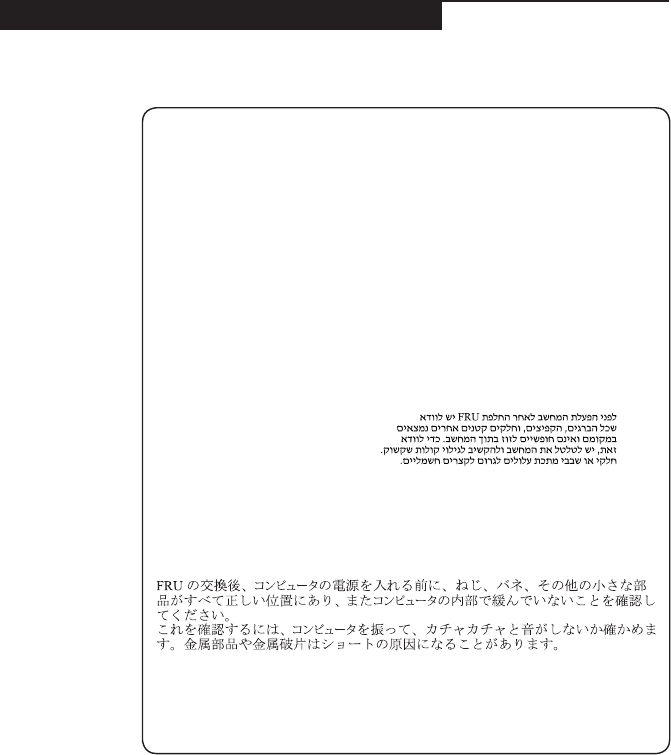
Safety notice 1
BeforethecomputerispoweredonafterFRUreplacement,makesureallscrews,
springs,andothersmallpartsareinplaceandarenotleftlooseinsidethe
computer.Verifythisbyshakingthecomputerandlisteningforrattlingsounds.
Metallicpartsormetalakescancauseelectricalshorts.
Avantderemettrel’ordinateursoustensionaprèsremplacementd’uneunitéen
clientèle,vériezquetouslesressorts,visetautrespiècessontbienenplaceet
bienxées.Pourcefaire,secouezl’unitéetassurez-vousqu’aucunbruitsuspect
neseproduit.Despiècesmétalliquesoudescopeauxdemétalpourraientcauser
uncourt-circuit.
BevornacheinemFRU-AustauschderComputerwiederangeschlossenwird,
mußsichergestelltwerden,daßkeineSchrauben,FedernoderandereKleinteile
fehlenoderimGehäusevergessenwurden.DerComputermußgeschütteltundauf
Klappergeräuschegeprüftwerden.Metallteileoder-splitterkönnenKurzschlüsse
erzeugen.
Primadiaccenderel’elaboratoredopocheéstataeffettuatalasostituzionediuna
FRU,accertarsichetutteleviti,lemolleetuttelealtripartidipiccoledimensioni
sianonellacorrettaposizioneenonsianosparseall’internodell’elaboratore.
Vericareciòscuotendol’elaboratoreeprestandoattenzioneadeventualirumori;
eventualipartiopezzettimetallicipossonoprovocarecortocircuitipericolosi.
AntesdeencenderelsistemadespuesdesustituirunaFRU,compruebeque
todoslostornillos,muellesydemáspiezaspequeñasseencuentranensusitio
ynoseencuentransueltasdentrodelsistema.Compruébeloagitandoelsistema
yescuchandolosposiblesruidosqueprovocarían.Laspiezasmetálicaspueden
causarcortocircuitoseléctricos.
8
Z410/Z510/Z510 Touch Hardware Maintenance Manual
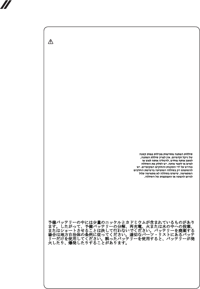
Safety notice 2
DANGER
Somestandbybatteriescontainasmallamountofnickelandcadmium.Donot
disassembleastandbybattery,rechargeit,throwitintofireorwater,orshort-
circuitit.Disposeofthebatteryasrequiredbylocalordinancesorregulations.
Useonlythebatteryintheappropriatepartslisting.Useofanincorrectbatterycan
resultinignitionorexplosionofthebattery.
Certainesbatteriesdesecourscontiennentdunickeletducadmium.Neles
démontezpas,nelesrechargezpas,nelesexposezniaufeuniàl’eau.Ne
lesmettezpasencourt-circuit.Pourlesmettreaurebut,conformez-vousàla
réglementationenvigueur.Lorsquevousremplacezlapiledesauvegardeoucelle
del’horlogetempsréel,veillezàn’utiliserquelesmodèlescitésdanslalistede
piècesdétachéesadéquate.Unebatterieouunepileinappropriéerisquedeprendre
feuoud’exploser.
DieBereitschaftsbatterie,diesichunterdemDiskettenlaufwerkbefindet,
kanngeringeMengenNickelundCadmiumenthalten.Siedarfnichtzerlegt,
wiederaufgeladen,kurzgeschlossen,oderFeueroderWasserausgesetztwerden.
BeiderEntsorgungdieörtlichenBestimmungenfürSondermüllbeachten.Beim
ErsetzenderBereitschafts-oderSystembatterienurBatteriendesTypsverwenden,
derinderErsatzteillisteaufgeführtist.DerEinsatzfalscherBatterienkannzu
EntzündungoderExplosionführen.
Alcunebatteriediriservacontengonounapiccolaquantitàdinichelecadmio.
Nonsmontarle,ricaricarle,gettarlenelfuocoonell’acquanécortocircuitarle.
Smaltirlesecondolanormativainvigore(DPR915/82,successivedisposizionie
disposizionilocali).Quandosisostituiscelabatteriadell’RTC(realtimeclock)o
labatteriadisupporto,utilizzaresoltantoitipiinseritinell’appropriatoCatalogo
parti.L’impiegodiunabatterianonadattapotrebbedeterminarel’incendioo
l’esplosionedellabatteriastessa.
Algunasbateríasdereservacontienenunapequeñacantidaddeníquelycadmio.
Nolasdesmonte,nirecargue,nilasechealfuegooalaguanilascortocircuite.
Deséchelastalcomodisponelanormativalocal.Utilicesólobateríasquese
encuentrenenlalistadepiezas.Lautilizacióndeunabateríanoapropiadapuede
provocarlaigniciónoexplosióndelamisma.
9
Safety information
Safety notice 3
DANGER
Thebatterypackcontainssmallamountsofnickel.Donotdisassembleit,throw
itintoreorwater,orshort-circuitit.Disposeofthebatterypackasrequiredby
localordinancesorregulations.Useonlythebatteryintheappropriatepartslisting
whenreplacingthebatterypack.Useofanincorrectbatterycanresultinignition
orexplosionofthebattery.
Labatteriecontientdunickel.Neladémontezpas,nel’exposezniaufeuniàl’eau.
Nelamettezpasencourt-circuit.Pourlamettreaurebut,conformez-vousàla
réglementationenvigueur.Lorsquevousremplacezlabatterie,veillezàn’utiliser
quelesmodèlescitésdanslalistedepiècesdétachéesadéquate.Eneffet,une
batterieinappropriéerisquedeprendrefeuoud’exploser.
AkkusenthaltengeringeMengenvonNickel.Siedürfennichtzerlegt,
wiederaufgeladen,kurzgeschlossen,oderFeueroderWasserausgesetztwerden.
BeiderEntsorgungdieörtlichenBestimmungenfürSondermüllbeachten.Beim
ErsetzenderBatterienurBatteriendesTypsverwenden,derinderErsatzteilliste
aufgeführtist.DerEinsatzfalscherBatterienkannzuEntzündungoderExplosion
führen.
Labatteriacontienepiccolequantitàdinichel.Nonsmontarla,gettarlanelfuoco
onell’acquanécortocircuitarla.Smaltirlasecondolanormativainvigore(DPR
915/82,successivedisposizioniedisposizionilocali).Quandosisostituiscela
batteria,utilizzaresoltantoitipiinseritinell’appropriatoCatalogoparti.L’impiego
diunabatterianonadattapotrebbedeterminarel’incendiool’esplosionedella
batteriastessa.
Lasbateríascontienenpequeñascantidadesdeníquel.Nolasdesmonte,ni
recargue,nilasechealfuegooalaguanilascortocircuite.Deséchelastalcomo
disponelanormativalocal.Utilicesólobateríasqueseencuentrenenlalistade
piezasalsustituirlabatería.Lautilizacióndeunabateríanoapropiadapuede
provocarlaigniciónoexplosióndelamisma.
10
Z410/Z510/Z510 Touch Hardware Maintenance Manual
Safety notice 4
DANGER
Thelithiumbatterycancauseafire,anexplosion,orasevereburn.Donot
rechargeit,removeitspolarizedconnector,disassembleit,heatitabove100°C
(212°F),incinerateit,orexposeitscellcontentstowater.Disposeofthebatteryas
requiredbylocalordinancesorregulations.Useonlythebatteryintheappropriate
partslisting.Useofanincorrectbatterycanresultinignitionorexplosionofthe
battery.
Lapiledesauvegardecontientdulithium.Elleprésentedesrisquesd’incendie,
d’explosionoudebrûluresgraves.Nelarechargezpas,neretirezpasson
connecteurpolariséetneladémontezpas.Nel’exposezpasàunetemperature
supérieureà100°C,nelafaitespasbrûleretn’enexposezpaslecontenuàl’eau.
Mettezlapileaurebutconformémentàlaréglementationenvigueur.Unepile
inappropriéerisquedeprendrefeuoud’exploser.
DieSystembatterieisteineLithiumbatterie.Siekannsichentzünden,explodieren
oderschwereVerbrennungenhervorrufen.BatteriendiesesTypsdürfennicht
aufgeladen,zerlegt,über100Cerhitztoderverbranntwerden.Auchdarfihr
InhaltnichtmitWasserinVerbindunggebrachtoderderzurrichtigenPolung
angebrachteVerbindungssteckerentferntwerden.BeiderEntsorgungdieörtlichen
BestimmungenfürSondermüllbeachten.BeimErsetzenderBatterienurBatterien
desTypsverwenden,derinderErsatzteillisteaufgeführtist.DerEinsatzfalscher
BatterienkannzuEntzündungoderExplosionführen.
Labatteriadisupportoeunabatteriaallitioepuoincendiarsi,esplodereo
procuraregraviustioni.Evitarediricaricarla,smontarneilconnettorepolarizzato,
smontarla,riscaldarlaadunatemperaturasuperioreai100gradicentigradi,
incendiarlaogettarlainacqua.Smaltirlasecondolanormativainvigore(DPR
915/82,successivedisposizioniedisposizionilocali).L’impiegodiunabatteria
nonadattapotrebbedeterminarel’incendiool’esplosionedellabatteriastessa.
Labateríaderepuestoesunabateríadelitioypuedeprovocarincendios,
explosionesoquemadurasgraves.Nolarecargue,niquiteelconectorpolarizado,
niladesmonte,nicalienteporencimadelos100°C(212°F),nilaincinereni
expongaelcontenidodesusceldasalagua.Deséchelatalcomodisponela
normativalocal.
11
Safety information
Safety notice 5
IftheLCDbreaksandtheuidfrominsidetheLCDgetsintoyoureyesoronyour
hands,immediatelywashtheaffectedareaswithwateratleastfor15minutes.
Seekmedicalcareifanysymptomscausedbytheuidarepresentafterwashing.
Silepanneaud’afchageàcristauxliquidessebriseetquevousrecevezdansles
yeuxousurlesmainsunepartieduuide,rincez-lesabondammentpendantau
moinsquinzeminutes.Consultezunmédecinsidessymptômespersistentaprèsle
lavage.
DieLeuchtstoffröhreimLCD-BildschirmenthältQuecksilber.BeiderEntsorgung
dieörtlichenBestimmungenfürSondermüllbeachten.DerLCD-Bildschirm
bestehtausGlasundkannzerbrechen,wennerunsachgemäßbehandeltwird
oderderComputeraufdenBodenfällt.WennderBildschirmbeschädigtistund
diedarinbefindlicheFlüssigkeitinKontaktmitHautundAugengerät,sollten
diebetroffenenStellenmindestens15MinutenmitWasserabgespültundbei
BeschwerdenanschließendeinArztaufgesuchtwerden.
Nelcasochecasol’LCDsidovesserompereedilliquidoinessocontenuto
entrasseincontattocongliocchiolemani,lavareimmediatamenteleparti
interessateconacquacorrenteperalmeno15minuti;poiconsultareunmedicosei
sintomidovesseropermanere.
SilaLCDserompeyeluidodesuinteriorentraencontactoconsusojososus
manos,laveinmediatamentelasáreasafectadasconaguadurante15minutos
comomínimo.Obtengaatenciónmedicasisepresentaalgúnsíntomadeluido
despuesdelavarse.
12
Z410/Z510/Z510 Touch Hardware Maintenance Manual
Safety notice 6
DANGER
Toavoidshock,donotremovetheplasticcoverthatprotectsthelowerpartofthe
invertercard.
And’évitertoutrisquedechocélectrique,neretirezpaslecacheenplastique
protégeantlapartieinférieuredelacarted’alimentation.
AusSicherheitsgründendieKunststoffabdeckung,diedenunterenTeilder
Spannungswandlerplatineumgibt,nichtentfernen.
Perevitarescosseelettriche,nonrimuoverelacoperturainplasticacheavvolgela
parteinferioredellaschedainvertitore.
Paraevitardescargas,noquitelacubiertadeplásticoquerodealapartebajadela
tarjetainvertida.
Safety notice 7
DANGER
Thoughthemainbatterieshavelowvoltage,ashortedorgroundedbatterycan
produceenoughcurrenttoburnpersonnelorcombustiblematerials.
Bienquelevoltagedesbatteriesprincipalessoitpeuélevé,lecourt-circuitoula
miseàlamassed’unebatteriepeutproduiresufsammentdecourantpourbrûler
desmatériauxcombustiblesoucauserdesbrûlurescorporellesgraves.
ObwohlHauptbatterieneineniedrigeSpannunghaben,könnensiedochbei
KurzschlußoderErdunggenugStromabgeben,umbrennbareMaterialienzu
entzündenoderVerletzungenbeiPersonenhervorzurufen.
Sebbenelebatteriedialimentazionesianoabassovoltaggio,unabatteriain
cortocircuitooamassapuòfornirecorrentesufficientedabruciaremateriali
combustibilioprovocareustioniaitecnicidimanutenzione.
Aunquelasbateríasprincipalestienenunvoltajebajo,unabateríacortocircuitada
oconcontactoatierrapuedeproducirlacorrientesucientecomoparaquemar
materialcombustibleoprovocarquemadurasenelpersonal.
13
Safety information
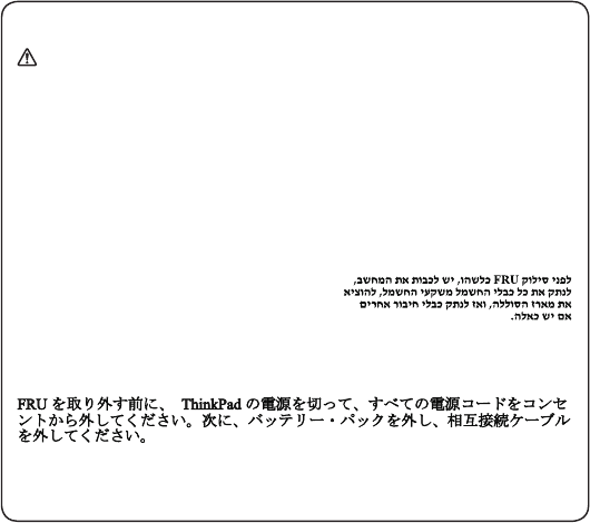
Safety notice 8
DANGER
BeforeremovinganyFRU,turnoffthecomputer,unplugallpowercordsfrom
electricaloutlets,removethebatterypack,andthendisconnectanyinterconnecting
cables.
Avantderetireruneunitéremplaçableenclientèle,mettezlesystèmehorstension,
débrancheztouslescordonsd’alimentationdessoclesdeprisedecourant,retirez
labatterieetdéconnecteztouslescordonsd’interface.
DieStromzufuhrmußabgeschaltet,alleStromkabelausderSteckdosegezogen,
derAkkuentferntundalleVerbindungskabelabgenommensein,bevoreineFRU
entferntwird.
PrimadirimuoverequalsiasiFRU,spegnereilsistema,scollegaredalleprese
elettrichetuttiicavidialimentazione,rimuoverelabatteriaepoiscollegareicavi
diinterconnessione.
AntesdequitarunaFRU,apagueelsistema,desenchufetodosloscablesde
lastomasdecorrienteeléctrica,quitelabateríay,acontinuación,desconecte
cualquiercabledeconexiónentredispositivos.
14
Z410/Z510/Z510 Touch Hardware Maintenance Manual
Laser compliance statement
Some models of Lenovo computer are equipped from the factory with an
optical storage device such as a CD-ROM drive or a DVD-ROM drive. Such
devices are also sold separately as options. If one of these drives is installed,
it is certied in the U.S. to conform to the requirements of the Department of
Health and Human Services 21 Code of Federal Regulations (DHHS 21 CFR)
Subchapter J for Class 1 laser products. Elsewhere, the drive is certified to
conform to the requirements of the International Electrotechnical Commission
(IEC) 825 and CENELEC EN 60 825 for Class 1 laser products.
If a CD-ROM drive, a DVD-ROM drive, or another laser device is installed, note
the following:
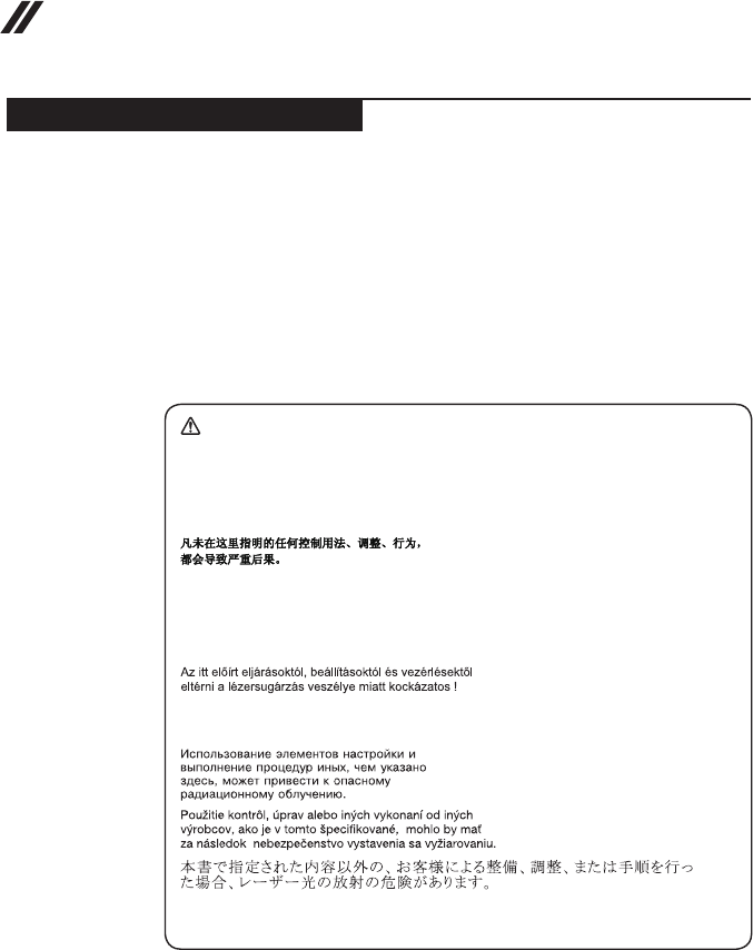
CAUTION
Useofcontrolsoradjustmentsorperformanceofproceduresotherthanthose
speciedhereinmightresultinhazardousradiationexposure.
Ousodecontroles,ajustesoudesempenhodeprocedimentosdiferentesdaqueles
aquiespecicadospoderesultaremperigosaexposiçãoàradiação.
Pourévitertoutrisqued’expositionaurayonlaser,respectezlesconsignesde
réglageetd’utilisationdescommandes,ainsiquelesprocéduresdécrites.
WerdenSteuer-undEinstellelementeandersalshierfestgesetztverwendet,kann
gefährlicheLaserstrahlungauftreten.
L’utilizzodicontrolli,regolazioniol’esecuzionediprocedurediversedaquelle
specicatepossonoprovocarel’esposizionea.
Elusodecontrolesoajustesolaejecucióndeprocedimientosdistintosdelosaquí
especicadospuedeprovocarlaexposiciónaradiacionespeligrosas.
Opening the CD-ROM drive, the DVD-ROM drive, or any other optical storage
device could result in exposure to hazardous laser radiation. There are no
serviceable parts inside those drives. Do not open.
15
Safety information
A CD-ROM drive, a DVD-ROM drive, or any other storage device installed may
contain an embedded Class 3A or Class 3B laser diode. Note the following:
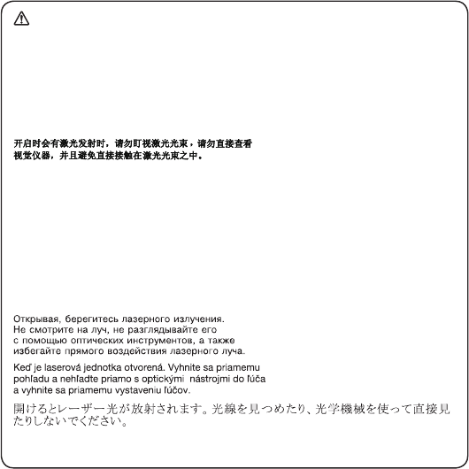
DANGER
Emitsvisibleandinvisiblelaserradiationwhenopen.Donotstareintothebeam,
donotviewdirectlywithopticalinstruments,andavoiddirectexposuretothe
beam.
Radiaçãoporraiolaseraoabrir.Nãoolhefixonofeixedeluz,nãoolhe
diretamentepormeiodeinstrumentosóticoseeviteexposiçãodiretacomofeixe
deluz.
Rayonnementlasersicarterouvert.Évitezdefixerlefaisceau,deleregarder
directementavecdesinstrumentsoptiques,oudevousexposeraurayon.
LaserstrahlungbeigeöffnetemGerät.NichtdirektoderüberoptischeInstrumente
indenLaserstrahlsehenunddenStrahlungsbereichmeiden.
Kinyitáskorlézersugár!Nenézzenbeleseszabadszemmel,seoptikai
eszközökkel.Kerüljeasugárnyalábbalvalóérintkezést!
Aprendol’unitàvengonoemesseradiazionilaser.Nonfissareilfascio,non
guardarlodirettamenteconstrumentiotticieevitarel’esposizionedirettaalfascio.
Radiaciónláseralabrir.Nomirejamenteniexamineconinstrumentalópticoel
hazdeluz.Evitelaexposicióndirectaalhaz.
16
Z410/Z510/Z510 Touch Hardware Maintenance Manual
Important service information
This chapter presents the following important service information:
• “Strategy for replacing FRUs” on page 16
– “Strategy for replacing a hard disk drive” on page 17
– “Important notice for replacing a system board” on page 17
• “Important information about replacing RoHS compliant FRUs” on page 18
Important:
BIOSanddevicedriverxesarecustomer-installable.TheBIOSanddevicedrivers
arepostedonthecustomersupportsite:
http://support.lenovo.com.
Strategy for replacing FRUs
Before replacing parts:
Make sure that all software xes, drivers, and BIOS downloads are installed
before replacing any FRUs listed in this manual.
After a system board is replaced, ensure that the latest BIOS is loaded to the
system board before completing the service action.
To download software xes, drivers, and BIOS, follow the steps below:
1. Go to http://support.lenovo.com.
2. Enter the serial number or select a product or use Lenovo smart
downloading.
3. Select the BIOS/Driver/Applications and download.
4. Follow the directions on the screen and install the necessary software.
17
Important service information
Use the following strategy to prevent unnecessary expense for replacing and
servicing FRUs:
• If you are instructed to replace an FRU, but the replacement does not solve
the problem, reinstall the original FRU before you continue.
• Some computers have both a processor board and a system board. If you
are instructed to replace either of them, and replacing one of them does not
solve the problem, reinstall that board, and then replace the other one.
• If an adapter or a device consists of more than one FRU, any of the FRUs
may be the cause of the error. Before replacing the adapter or device,
remove the FRUs one by one to see if the symptoms change. Replace only
the FRU that changed the symptoms.
Attention: The setup configuration on the computer you are servicing may
have been customized. Running Automatic Conguration may alter the settings.
Note the current conguration settings (using the View Conguration option);
then, when service has been completed, verify that those settings remain in
effect.
Strategy for replacing a hard disk drive
Always try to run a low-level format before replacing a hard disk drive. This
will cause all customer data on the hard disk to be lost. Make sure that the
customer has a current backup of the data before performing this action.
Attention: The drive startup sequence in the computer you are servicing may
have been changed. Be extremely careful during write operations such as
copying, saving, or formatting. If you select an incorrect drive, data or programs
can be overwritten.
Important notice for replacing a system board
Some components mounted on a system board are very sensitive. Improper
handling can cause damage to those components, and may cause a system
malfunction.
Attention: When handling a system board:
• Do not drop the system board or apply any excessive force to it.
• Avoid rough handling of any kind.
• Avoid bending the system board and hard pushing to prevent cracking at
each BGA (Ball Grid Array) chipset.

18
Z410/Z510/Z510 Touch Hardware Maintenance Manual
Important information about replacing RoHS compliant FRUs
RoHS, The Restriction of Hazardous Substances in Electrical and
Electronic Equipment Directive (2002/95/EC) is a European Union legal
requirement affecting the global electronics industry. RoHS requirements
must be implemented on Lenovo products placed on the market after
June 2006. Products on the market before June 2006 are not required to
have RoHS compliant parts. If the original FRU parts are non-compliant,
replacement parts can also be non-compliant. In all cases if the original
FRU parts are RoHS compliant, the replacement part must also be RoHS
compliant.
Note: RoHS and non-RoHS FRU part numbers with the same t and function
are identied with unique FRU part numbers.
Lenovo plans to transit to RoHS compliance well before the implementation
date and expects its suppliers to be ready to support Lenovo’s requirements
and schedule in the EU. Products sold in 2005 and 2006 will contain some
RoHS compliant FRUs. The following statement pertains to these products and
any product Lenovo produces containing RoHS compliant FRUs.
RoHS compliant FRUs have unique FRU part numbers. Before or after the
RoHS implementation date, failed RoHS compliant parts must always be
replaced with RoHS compliant ones, so only the FRUs identied as compliant
in the system HMM or direct substitutions for those FRUs may be used.
Products marketed before June 2006 Products marketed after June 2006
Current or
original part
Replacement FRU Current or
original part
Replacement FRU
Non-RoHS Can be Non-RoHS
Must be RoHS Must be RoHS
Non-RoHS Can be RoHS
Non-RoHS Can sub to RoHS
RoHS Must be RoHS
Note: A direct substitution is a part with a different FRU part number that is
automatically shipped by the distribution center at the time of the order.

19
General checkout
General checkout
This chapter presents the following information:
• “What to do rst” on page 20
• “Power system checkout” on page 21
Before you go to the checkout, make sure to read the following important notes:
Important notes:
• Onlycertiedtrainedpersonnelcanservicethecomputer.
• BeforereplacinganyFRU,readthe entirepageonremovingandreplacing
FRUs.
• CarefullyremovescrewsforreusewhenreplacingFRUs.
• Beextremelycarefulduringsuchwriteoperationsascopying,saving,or
formatting.Drivesinthecomputerthatyouareservicingsequencemight
havebeenaltered.Ifyouselectanincorrectdrive,dataorprogramsmightbe
overwritten.
• ReplaceanFRUonlywithanotherFRUofthecorrectmodel.Whenyou
replaceanFRU,makesurethatthemachinemodelandtheFRUpartnumberare
correctbyreferringtotheFRUpartslist.
• AnFRUshouldnotbereplacedjustbecauseofasingle,unreproduciblefailure.
Singlefailurescanoccurforavarietyofreasonsthathavenothingtodowitha
hardwaredefect,suchascosmicradiation,electrostaticdischarge,orsoftware
errors.ConsiderreplacinganFRUonlywhenaproblemrecurs.Ifyoususpectthat
anFRUisdefective,cleartheerrorlogsandrunthetestagain.Iftheerrordoes
notrecur,donotreplacetheFRU.
• BecarefulnottoreplaceanondefectiveFRU.

20
Z410/Z510/Z510 Touch Hardware Maintenance Manual
What to do rst
When you do return an FRU, you must include the following information in the
parts exchange form or parts return form that you attach to it:
1. Name and phone number of servicer
2. Date of service
3. Date on which the machine failed
4. Date of purchase
5. Procedure index and page number in which the failing FRU was detected
6. Failing FRU name and part number
7. Machine type, model number, and serial number
8. Customer’s name and address
Note for warranty: During the warranty period, the customer may be
responsible for repair costs if the computer damage was caused by misuse,
accident, modification, unsuitable physical or operating environment, or
improper maintenance by the customer.
The following is a list of some common items that are not covered under
warranty and some symptoms that might indicate that the system was
subjected to stress beyond normal use.
Before checking problems with the computer, determine whether the damage is
covered under the warranty by referring to the following list:
The following are not covered under warranty:
• LCD panel cracked from the application of excessive force or from being
dropped
• Scratched (cosmetic) parts
• Distortion, deformation, or discoloration of the cosmetic parts
• Plastic parts, latches, pins, or connectors that have been cracked or broken
by excessive force
• Damage caused by liquid spilled into the system
• Damage caused by the improper insertion of a PC Card or the installation of
an incompatible card
• Improper disc insertion or use of an optical drive
• Diskette drive damage caused by pressure on the diskette drive cover,
foreign material in the drive, or the insertion of a diskette with multiple labels
• Damaged or bent diskette eject button
• Fuses blown by attachment of a nonsupported device
• Forgotten computer password (making the computer unusable)
• Sticky keys caused by spilling a liquid onto the keyboard
• Use of an incorrect AC adapter on laptop products
The following symptoms might indicate damage caused by nonwarranted
activities:
• Missing parts might be a symptom of unauthorized service or modication.
• If the spindle of a hard disk drive becomes noisy, it may have been subjected
to excessive force, or dropped.
21
General checkout
Power system checkout
To verify a symptom, follow the steps below:
1. Turn off the computer.
2. Connect the AC adapter.
3. Make sure that power is supplied when you turn on the computer.
4. Turn off the computer.
5. Disconnect the AC adapter.
6. Make sure that the battery pack supplies power when you turn on the
computer.
If you suspect a power problem, see the appropriate one of the following power
supply checkouts:
• “Checking the AC adapter” on page 21
• “Checking operational charging” on page 21
Checking the AC adapter
You are here because the computer fails only when the AC adapter is used.
• If the power-on indicator does not turn on, check the power cord of the AC
adapter for correct continuity and installation.
• If the computer does not charge during operation, go to “Checking
operational charging”.
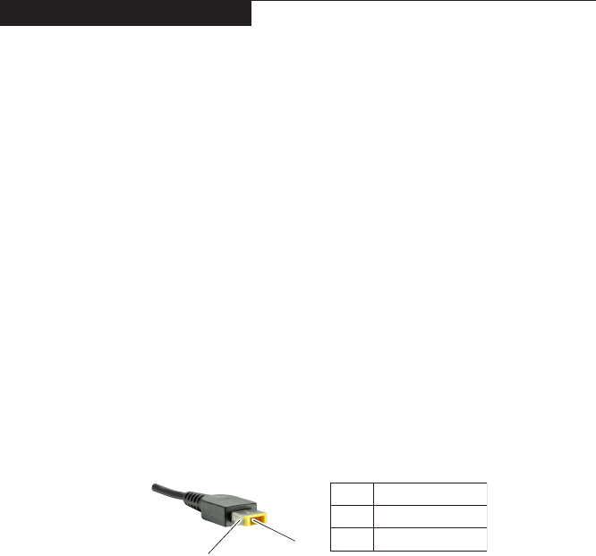
To check the AC adapter, follow the steps below:
1. Unplug the AC adapter cable from the computer.
2. Measure the output voltage at the plug of the AC adapter cable. See the
following gure:
1
2
Voltage (V DC)
+20
0
Pin
1
2
Note: Output voltage for the AC adapter pin No. 2 may differ from the one you
are servicing.
3. If the voltage is not correct, replace the AC adapter.
4. If the voltage is acceptable, do the following:
• Replace the system board.
• If the problem persists, go to “Lenovo Z410/Z510/Z510 Touch” on page 26.
Note: Noise from the AC adapter does not always indicate a defect.
Checking operational charging
To check whether the battery charges properly during operation, use a
discharged battery pack or a battery pack that has less than 50% of the total
power remaining when installed in the computer.

22
Z410/Z510/Z510 Touch Hardware Maintenance Manual
Perform operational charging. If the battery status indicator or icon does not
light on, remove the battery pack and let it return to room temperature. Reinstall
the battery pack. If the charge indicator or icon is still off, replace the battery
pack.
If the charge indicator still does not light on, replace the system board. Then
reinstall the battery pack.
23
Related service information
Related service information
This chapter presents the following information:
• “Restoring the factory contents by using OneKey Recovery” on page 23
• “Passwords” on page 24
• “Power management” on page 25
Restoring the factory contents by using OneKey Recovery
Restore of factory default
The Lenovo Z410/Z510/Z510 Touch computers come with pre-installed OneKey
Recovery System.In order to save application files and the initial backed up
files of the system, the hard disk in a Lenovo computer includes a hidden
partition when it is shipped. If you need to restore the system to the point of
your rst boot up, just enter Lenovo OneKey Recovery System and run System
Recovery. For details of OneKey Recovery System, see the User Guide for
Lenovo OneKey Recovery system.
Note:Thiswilldeleteallthenewdataonthesystempartition(Cdrive),which
isnotrecoverable.Makesuretobackupyourcriticaldatabeforeyouperformthis
action.
When you use the recovery discs to boot your computer, the system will enter
the user interface for system recovery automatically. Please follow the prompt
to insert the backup discs to complete the whole recovery process.
Note: Therecoveryprocessmighttakeupto2hours.

24
Z410/Z510/Z510 Touch Hardware Maintenance Manual
Passwords
As many as three passwords may be needed for any Lenovo computer: the
power-on password (POP) , Hard-disk password, and the supervisor password
(SVP).
If any of these passwords has been set, a prompt for it appears on the screen
whenever the computer is turned on. The computer does not start until the
password is entered.
Power-on password
A power-on password (POP) protects the system from being powered on by
an unauthorized person. The password must be entered before an operating
system can be booted.
Hard-disk password
There are two hard-disk passwords (HDPs):
+ User HDP - for the user
+ Master HDP - for the system administrator, who can use it to get access to
the hard disk drive even if the user has changed the user HDP
Attention: If the user HDP has been forgotten, check whether a master HDP
has been set. If it has, it can be used for access to the hard disk drive. If
no master HDP is available, neither Lenovo nor Lenov authorized service
technicians provide any services to reset either the user or the master HDP, or
to recover data from the hard disk drive. The hard disk drive can be replaced
for a scheduled fee.
Administrator password
If the Administrator password has been forgotten and cannot be made available
to the servicer, there is no service procedure to reset the password. The system
board must be replaced for a scheduled fee.

25
Related service information
Power management
Note: Power management modes are not supported for APM operating system.
To reduce power consumption, the computer has two power management
modes: screen blank and sleep (standby).
Screen blank mode
If the time set on the “Turn off monitor” timer in the operating system expires,
the LCD backlight turns off.
To end screen blank mode and resume normal operation, press any key.
Sleep (standby) mode
When the computer enters sleep (standby) mode, the following events occur in
addition to what occurs in screen blank mode:
• The LCD is powered off.
• The hard disk drive is powered off.
• The CPU stops.
To enter sleep (standby) mode, To put the computer to sleep, do one of the
following:
• Close the display panel.
• Press the power button.
• Open the Charms and then select Settings → Power → Sleep.
Attention: Wait until the power indicator light starts blinking (indicating that
the computer is in sleep mode) before you move your computer. Moving your
computer while the hard disk is spinning can damage the hard disk, causing
loss of data.
To wake the computer, do one of the following:
• Press any key on the keyboard.
• Press the power button.
26
Z410/Z510/Z510 Touch Hardware Maintenance Manual
Lenovo Z410/Z510/Z510 Touch
This chapter presents the following product-specific service references and
product-specic parts information:
• “Specications” on page 26
• “Status indicators” on page 28
• “Function key combinations” on page 30
• “FRU replacement notices” on page 31
• “Removing and replacing an FRU” on page 32
• “Locations” on page 81
• “Parts list” on page 84
Specications
The following table lists the specifications of the Lenovo Z410/Z510/Z510
Touch:
Table 1. Specications
Feature Description
Processor • View the system properties of your computer.
You can do this as follows: Open the Control Panel, and then
select System and Security → System.
Core Chipset • Intel Panther Point HM86
Bus architecture • GPU: PCIe 3.0, 8 GT/s
• WLAN: PCIe 2.0, 5 GT/s
• RAM: DDR3L, 1600 MT/s
• DMI x 4, 5 GT/s
• FDI x 2, 2.7 Gb/s
• LCD: eDP 1.2, 5.4 GT/s
• HDMI Port: HDMI 1.4, 1.65 GT/s
• HDD: SATA 3.0, 6 Gb/s
• ODD: SATA 1.0, 1.5 Gb/s
• USB Port: USB 3.0, 5 Gb/s
• USB 2.0, 480 Mb/s
• BT: USB2.0, 480 Mb/s
• Card Reader: SD3.0, 50 Mb/s
• VGA
• SMBus 2.0
• LPC 1.1
• HDA
• SPI
Graphic memory
chip
• Nvidia N14P-GV2
• Intel HD Graphics 4600
Display • 14" 16:9, 1366 × 768 pixels HD WXGA/200 nits, 1600x900
HD+/250 nits(option) (Z410)
• 15.6" 16:9, 1366 × 768 pixels WXGA/200 nits, FHD
1920x1080 pixels (Z510/Z510 Touch)

27
Lenovo Z410/Z510/Z510 Touch
Table 1. Specications (continued)
Feature Description
Standard
memory • DDR3-1600/1333MHz SODIMM × 2 (max 16 GB)
CMOS RAM • 256 Byte
Hard disk drive • 2.5-inch, 7 mm/9.5 mm SATA
• 500 GB / 750 GB / 1TB 5400 rpm /8GB + 500 GB SSHD/8GB
+ 1 TB SSHD
Optical drive • 2.5" Internal 9.5mm, Rambo, blue-ray Rambo (option)
I/O port • Combo audio jack × 1
• RJ45 × 1
• HDMI port × 1
• USB 2.0 port × 1, USB 3.0 port × 2
• 2 in 1 slot × 1 (SD/MMC)
Audio • 1/8" Combo audio jack
• 2 × 1.5 W speakers
Ethernet (on the
system board) • 10/100M
PCI Express
Mini Card slot • 1 slot
Bluetooth
wireless • Combo w/ Wi, BT 4.0 option
Keyboard • 6 Row, ISO Full Size Keyboard
Touch pad • Multi-touch type
Integrated
camera
• 0.3 M/1.0 M (HD) pixels (Z410/Z510)
• 1.0 M (HD) pixels (Z510 Touch)
Battery • 4 cell, 41.6 Wh or 48 Wh
AC adapter • 20 V, 65 W or 90 W
Pre-installed
operating
system
• Win8
28
Z410/Z510/Z510 Touch Hardware Maintenance Manual
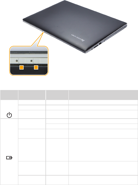
Status indicators
The system status indicators below show the computer status:
Z410
12
29
Lenovo Z410/Z510/Z510 Touch
Z510/Z510 Touch
12
Table 2. Status indicators
Indicator Indicator
status
Charge
Status Meaning
1
Power
On (solid white) --- The computer is powered on.
Blinking --- The computer is in sleep mode.
Off --- The computer is powered off.
2
Battery
On (solid white) Charging The battery has more than 80% charge.
Discharging The battery has more than 20% charge.
On (solid
amber) Discharging The battery has between 5% and 20%
charge.
Blinking slowly
(white) Charging
The battery has between 20% and
80% charge. When the battery reaches
80% charge, the light will stop blinking.
However, charging will continue until the
battery is fully charged.
Blinking slowly
(amber) Charging
The battery has less than 20% charge.
When battery charge reaches 20%, the
blinking color will change to white.
Blinking quickly
(amber)
Charging/
Discharging The battery has less than 5% charge.
30
Z410/Z510/Z510 Touch Hardware Maintenance Manual
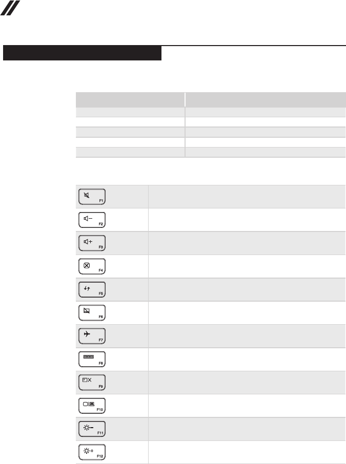
Function key combinations
The following table shows the function of each combination of function key.
Table 3. Fn key combinations
Key combination Description
Fn + PgUp: Enables/disables the scroll lock.
Fn + PgDn: Activates the system request.
Fn + Home: Activates the pause function.
Fn + End: Activates the break function.
Fn + Space (on select models): Enables/disables the keyboard backlight.
Table 4. Hotkeys
: Mutes/unmutes the sound.
: Decreases the volume level.
: Increases the volume level.
: Closes the currently active window.
: Refreshes the desktop or the currently active window.
: Enables/disables the touchpad.
:Enables/disables Airplane mode.
: Displays all currently active apps.
: Turns on/off the backlight of the LCD screen.
:Toggles the display between the computer and an external
device.
: Decreases display brightness.
: Increases display brightness.
31
Lenovo Z410/Z510/Z510 Touch
FRU replacement notices
This section presents notices related to removing and replacing parts. Read
this section carefully before replacing any FRU.
Screw notices
Loose screws can cause a reliability problem. In the Lenovo computer, this
problem is addressed with special nylon-coated screws that have the following
characteristics:
• They maintain tight connections.
• They do not easily come loose, even with shock or vibration.
• They are harder to tighten.
• Carefully remove screws for reuse when replacing FRUs.
Do the following when you service this machine:
• Keep the screw kit in your tool bag.
• Use a torque screwdriver if you have one.
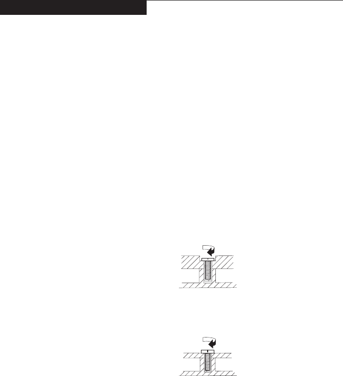
Tighten screws as follows:
• Plastic to plastic
Turn an additional 90° after the screw head touches the surface of the
plastic part:
more than 90°
(Cross-section)
• Logic card to plastic
Turn an additional 180° after the screw head touches the surface of the
logic card:
more than 180°
(Cross-section)
• Torque driver
If you have a torque screwdriver , refer to the “Torque” column for each step.
• Make sure that you use the correct screws. If you have a torque screwdriver,
tighten all screws rmly to the torque shown in the table. Carefully remove
screws for reuse when replacing FRUs. Make sure that all screws are
tightened rmly.
• Ensure torque screwdrivers are calibrated correctly following country
specications.
32
Z410/Z510/Z510 Touch Hardware Maintenance Manual
Removing and replacing an FRU
This section presents exploded gures with the instructions to indicate how to
remove and replace the FRU. Make sure to observe the following general rules:
1. Do not attempt to service any computer unless you have been trained and
certied. An untrained person runs the risk of damaging parts.
2. Before replacing any FRU, review “FRU replacement notices” on page 31.
3. Begin by removing any FRUs that have to be removed before the failing
FRU. Any of such FRUs are listed at the top of the page. Remove them in
the order in which they are listed.
4. Follow the correct sequence in the steps to remove the FRU, as given in the
gures by the numbers in square callouts.
5. When turning a screw to replace an FRU, turn it in the direction as given by
the arrow in the gure.
6. When removing the FRU, move it in the direction as given by the arrow in
the gure.
7. To put the new FRU in place, reverse the removal procedures and follow
any of the notes that pertain to replacement. For information about
connecting and arranging internal cables, see “Locations” on page 81.
8. When replacing an FRU, use the correct screw as shown in the procedures.
DANGER
BeforeremovinganyFRU,turnoffthecomputer,unplugallpowercordsfrom
electricaloutlets,andthendisconnectanyoftheinterconnectingcables.
Attention: After replacing an FRU, do not turn on the computer until you have
made sure that all screws, springs, and other small parts are in place and none
are loose inside the computer. Verify this by shaking the computer gently and
listening for rattling sounds. Metallic parts or metal akes can cause electrical
short circuits.
Attention: The system board is sensitive to, and can be damaged by,
electrostatic discharge. Before touching it, establish personal grounding by
touching a ground point with one hand or using an electrostatic discharge (ESD)
strap (P/N 6405959) to remove potential shock reasons.
33
Lenovo Z410/Z510/Z510 Touch
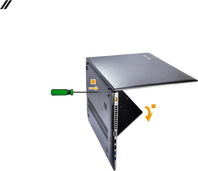
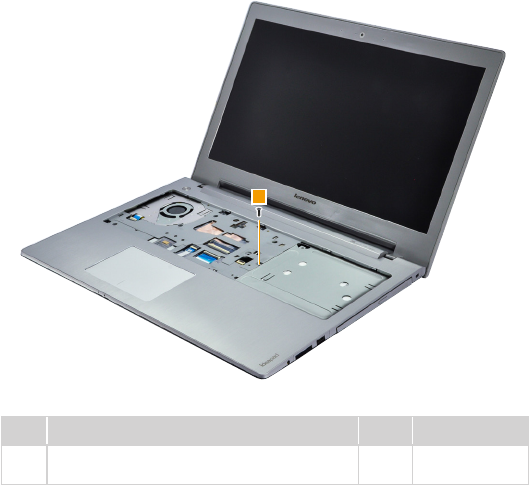
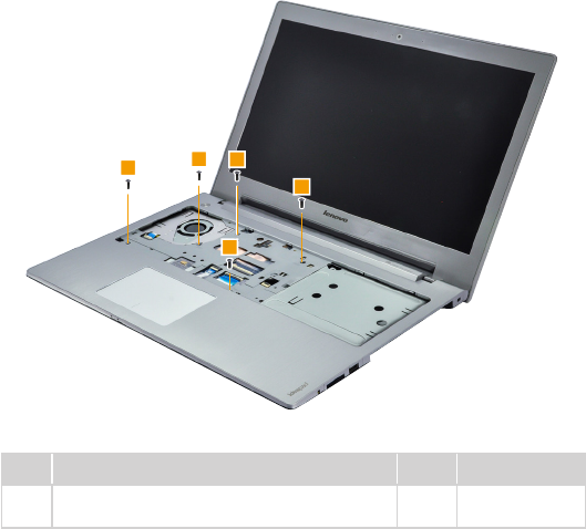
1010 Keyboard
Figure 1. Removal steps of keyboard
Remove the screws 1.
Z410
1
11
Z510/Z510 Touch
1
1
Step Screw (quantity) Color Torque
1M2 × 12 mm, at-head, nylok-coated (3) (Z410)
Logic Lower to K/B
Black 1.85+/-0.15 kgf/cm
1M2 × 4.9 mm, at-head, nylok-coated (3)
(Z510/Z510 Touch) Logic Lower to K/B
Black 1.85+/-0.15 kgf/cm
34
Z410/Z510/Z510 Touch Hardware Maintenance Manual
Figure 1. Removal steps of keyboard (continued)
Insert the screwdriver into one of the screw hole on the bottom 2. Then pull
the keyboard out of the keyboard bezel 3.
2
3
35
Lenovo Z410/Z510/Z510 Touch
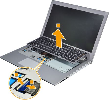
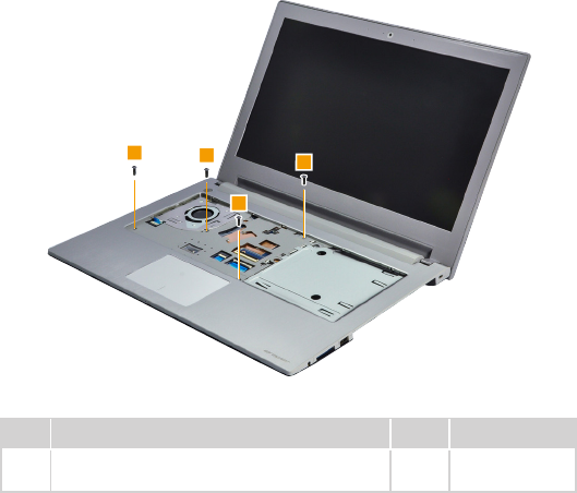
Figure 1. Removal steps of keyboard (continued)
Lift the keyboard a little, and then detach the connectors in the direction shown
by arrows 4 5. Remove the keyboard in the direction shown by arrow 6.
Z410
4
5
6
36
Z410/Z510/Z510 Touch Hardware Maintenance Manual
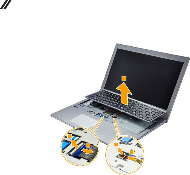
Figure 1. Removal steps of keyboard (continued)
Z510/Z510 Touch
4
54
5
6
When installing: Make sure that the FPC connector is attached rmly.
38
Z410/Z510/Z510 Touch Hardware Maintenance Manual
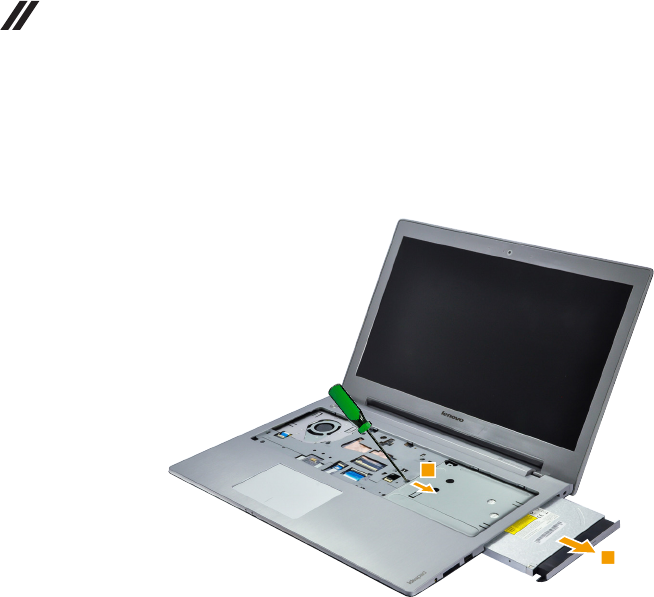
Figure 2. Removal steps of Optical drive (continued)
Insert a screwdriver into the screw hole and push the optical drive in the
direction shown by arrow 2. Pull the optical drive out in the direction shown by
arrow 3.
2
3
39
Lenovo Z410/Z510/Z510 Touch
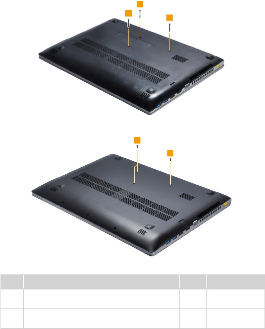
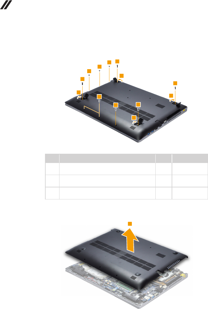
1030 Base cover
For access, remove this FRU:
• “1010 Keyboard” on page 33
• “1020 Optical drive” on page 37
Figure 3. Removal steps of base cover
Z410
Remove the screws 1.
1
1
1
1
Step Screw (quantity) Color Torque
1M2.5 × 6 mm, at-head, nylok-coated (4)
Logic Upper to Logic Lower
Black 3.0+/-0.3 kgf/cm
40
Z410/Z510/Z510 Touch Hardware Maintenance Manual
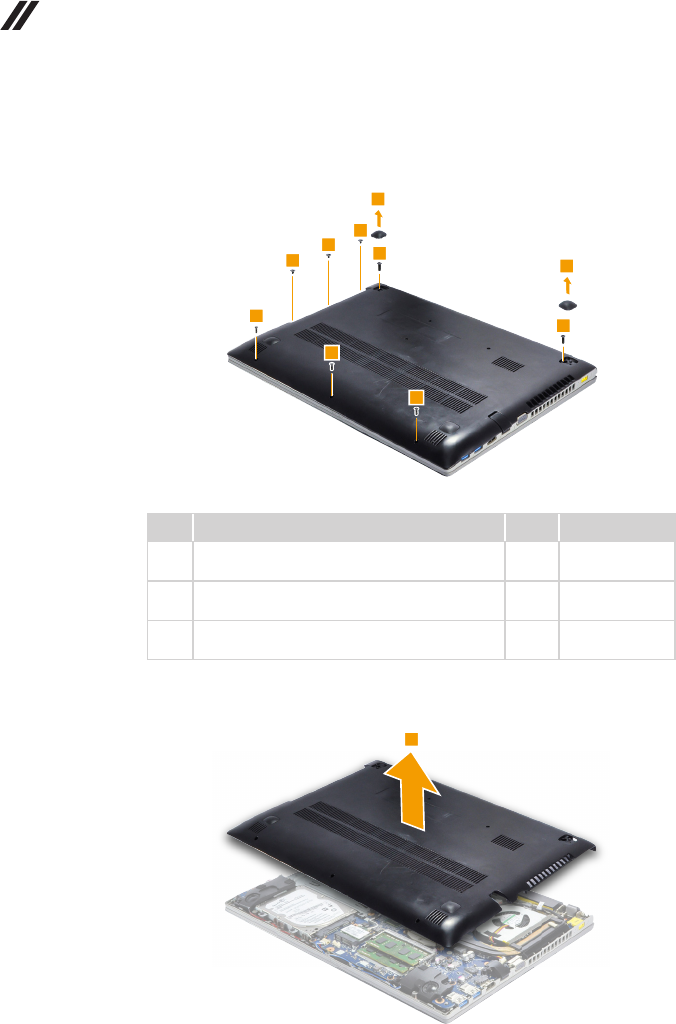
Figure 3. Removal steps of base cover (continued)
Remove the two rubber feet 2. Remove the screws 3,4 and 5 from the
bottom.
2
5
5
5
2
3
3
4
4
4
Step Screw (quantity) Color Torque
3M2.5 × 6 mm, at-head, nylok-coated (2)
Rubber foot to Logic Upper
Black 3.0+/-0.3 kgf/cm
4M2 × 4.9 mm, at-head, nylok-coated (3)
Logic Lower to Logic Upper
Black 1.85+/-0.15 kgf/cm
5M2 × 2.5 mm, at-head, nylok-coated (3)
Logic Lower to Logic Upper
Black 1.85+/-0.15 kgf/cm
Remove the base cover in the direction shown by arrow 6.
6
41
Lenovo Z410/Z510/Z510 Touch
Figure 3. Removal steps of base cover (continued)
Z510/Z510 Touch
Remove the screws 1.
111
1
1
Step Screw (quantity) Color Torque
1M2.5 × 6 mm, at-head, nylok-coated (5)
Logic Upper to Logic Lower
Black 3.0+/-0.3 kgf/cm
42
Z410/Z510/Z510 Touch Hardware Maintenance Manual
Figure 3. Removal steps of base cover (continued)
Open the four rubber feet 2. Remove the screws 3, 4 and 5 from the
bottom.
4
43
3
3
3
2
2
2
2
5
5
5
Step Screw (quantity) Color Torque
3M2.5 × 6 mm, at-head, nylok-coated (4)
Rubber foot to Logic Upper
Black 3.0+/-0.3 kgf/cm
4M2 × 4.9 mm, at-head, nylok-coated (3)
Logic Lower to Logic Upper
Black 1.85+/-0.15 kgf/cm
5M2 × 2.5 mm, at-head, nylok-coated (3)
Logic Lower to Logic Upper
Black 1.85+/-0.15 kgf/cm
Remove the base cover in the direction shown by arrow 6.
6
43
Lenovo Z410/Z510/Z510 Touch
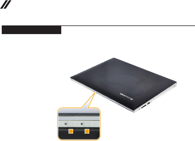
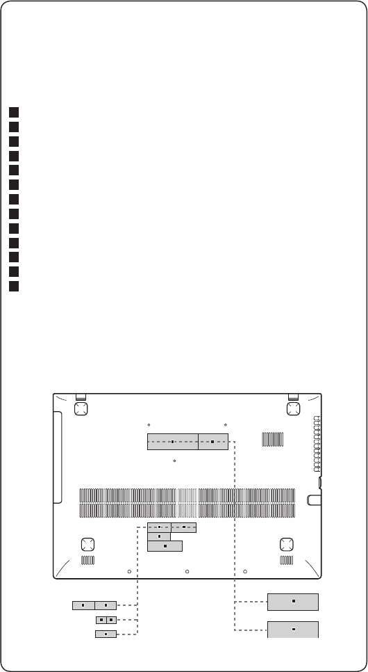
Note: Applying labels to the base cover
The new base cover FRU is shipped with a kit containing labels of several
kinds. When you replace the base cover, you need to apply the following
label:
The following labels need to be peeled off from the old base cover, and need
to be put on the new base cover.
a Rating label
b Rating label
c Rating label for China
d Rating label for WW
e Brazil BT label
f Brazil WL label
g BT label for US/CA/TW/INDONESIA
h WL label for US/CA/TW/INDONESIA
i SIRIM BT label
j SIRIM WL label
k Israel WL label
l Indonesia D side label
m KCC label
For some models, you also need to apply one or two FCC labels. Check the
old base cover; if it has one or two FCC labels, nd duplicates of them in the
label kit and apply them to the new base cover.
For the location of each label, refer to the following gure:
a b
e
l
gh
i
k
c
d
j
m
f
44
Z410/Z510/Z510 Touch Hardware Maintenance Manual
1040 Battery pack
For access, remove these FRUs in order:
• “1010 Keyboard” on page 33
• “1020 Optical drive” on page 37
• “1030 Base cover” on page 39
DANGER
Onlyusethebatteryspeciedinthepartslistforyourcomputer.Anyotherbattery
couldigniteorexplode.
Figure 4. Removal steps of battery pack
Detach the battery pack connector in the direction shown by arrow 1, remove
the screws 2.
1
2
2
Step Screw (quantity) Color Torque
2M2.5 × 6 mm, at-head, nylok-coated (2)
Logic Upper to Battery
black 3.0+/-0.3 kgf/cm
45
Lenovo Z410/Z510/Z510 Touch
Figure 4. Removal steps of battery pack (continued)
Remove the battery pack in the direction shown by arrow 3.
3
When installing: Make sure the battery pack connector is attached rmly.
46
Z410/Z510/Z510 Touch Hardware Maintenance Manual
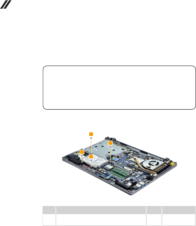
1050 Hard disk drive
For access, remove these FRUs in order:
• “1010 Keyboard” on page 33
• “1020 Optical drive” on page 37
• “1030 Base cover” on page 39
• “1040 Battery pack” on page 44
Attention:
• Donotdroptheharddiskdriveorapplyanyphysicalshocktoit.Thehard
diskdriveissensitivetophysicalshock.Improperhandlingcancausedamages
andpermanentlossofdata.
• Beforeremovingthedrive,suggestthecustomertobackupalltheinformationon
itifpossible.
• Neverremovethedrivewhilethesystemisoperatingorisinsuspendmode.
Figure 5. Removal steps of hard disk drive
Remove the screws 1.
1
1
1
1
Step Screw (quantity) Color Torque
1M2.5 × 3 mm, at-head, nylok-coated (4)
HDD to Logic Upper
Black 3.0+/-0.3 kgf/cm
47
Lenovo Z410/Z510/Z510 Touch
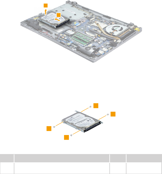
Figure 5. Removal steps of hard disk drive (continued)
Detach the HDD connector in the direction shown by arrow 2. Remove the
hard disk drive from the slot in the direction shown by arrow 3.
2
3
When installing: Make sure that the HDD connector is attached rmly.
Remove the screws 4, then take out the metal frame.
4
4
4
4
Step Screw (quantity) Color Torque
4M3 × 3 mm, at-head, nylok-coated (4)
HDD_BRK to module
White 3.0+/-0.3 kgf/cm
When installing: Make sure that the HDD connector is attached rmly.
48
Z410/Z510/Z510 Touch Hardware Maintenance Manual
1060 PCI Express Mini Card for wireless LAN
For access, remove these FRUs in order:
• “1010 Keyboard” on page 33
• “1020 Optical drive” on page 37
• “1030 Base cover” on page 39
• “1040 Battery pack” on page 44
Figure 6. Removal steps of PCI Express Mini Card for wireless LAN
Disconnect the two wireless LAN cables (black, white) 1, and then remove the
screw 2.
1
2
In step 1, unplug the jacks by using the removal tool antenna RF connector
(P/N: 08K7159), or pick up the connectors with your ngers and gently unplug
them in the direction shown by arrows.
Notes: wireless LAN card has 2 cables in step 1.
wireless LAN card in some models may have 3 cables in step 1.
Step Screw (quantity) Color Torque
2M2 × 2.5 mm, at-head, nylok-coated (1) WLAN
Card to MB
Black 1.85+/-0.15 kgf/cm
49
Lenovo Z410/Z510/Z510 Touch
Figure 6. Removal steps of PCI Express Mini Card for wireless LAN (continued)
Remove the card in the direction shown by arrow 3.
3
When installing:
• In models with a wireless LAN card that has two antenna connectors, plug
the black cable (1st) (MAIN) into the jack labeled 1, and the white cable (2nd)
(AUX) into jack labeled 2 on the card.
• In models with a wireless LAN card that has three antenna connectors, plug
the black cable (1st) (MAIN) into the jack labeled 1, the grey cable (3rd) into
jack labeled 3, and the white cable (2nd) (AUX) into jack labeled 2 on the
card.
50
Z410/Z510/Z510 Touch Hardware Maintenance Manual
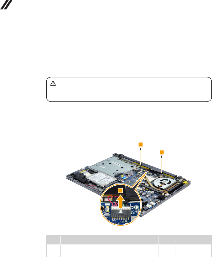
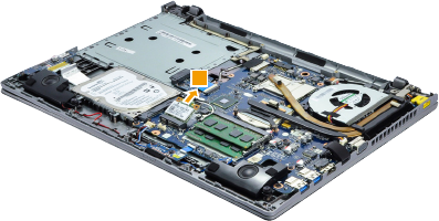
1070 DIMM
For access, remove these FRUs in order:
• “1010 Keyboard” on page 33
• “1020 Optical drive” on page 37
• “1030 Base cover” on page 39
• “1040 Battery pack” on page 44
Figure 7. Removal steps of DIMM
Release the two latches on both edges of the socket at the same time in the
direction shown by arrows 1, and then unplug the DIMM in the direction shown
by arrow 2.
11
2
When installing: Insert the notched end of the DIMM into the socket. Push the
DIMM rmly, and pivot it until it snaps into the place. Make sure that it is rmly
xed in the slot and difcult to be moved.
51
Lenovo Z410/Z510/Z510 Touch
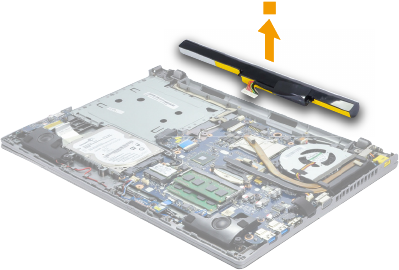
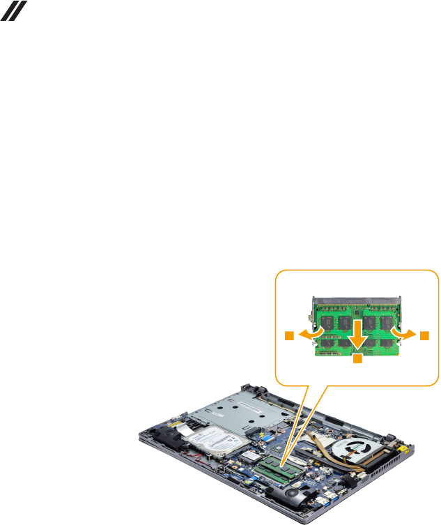
1080 Fan assembly and Heat Sink assembly
For access, remove these FRUs in order:
• “1010 Keyboard” on page 33
• “1020 Optical drive” on page 37
• “1030 Base cover” on page 39
• “1040 Battery pack” on page 44
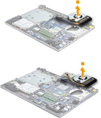
Figure 8. Removal steps of fan assembly and heat sink assembly
Detach the fan connector in the direction shown by arrow 1 , and then loosen
the screws 2 and remove the screw 3.
Z410
22
2
1
3
Step Screw (quantity) Color Torque
3M2 × 3, at-head, nylok-coated (1)
FAN to Logic Upper
Black 1.85+/-0.15 kgf/cm
52
Z410/Z510/Z510 Touch Hardware Maintenance Manual
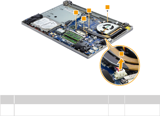
Figure 8. Removal steps of fan assembly and heat sink assembly (continued)
Z510/Z510 Touch
1
3
2
22
2
Step Screw (quantity) Color Torque
3M2 × 3.2, at-head, nylok-coated (1)
FAN to Logic Upper
Black 1.85+/-0.15 kgf/cm
When installing: Make sure that the fan connector is attached firmly to the
system board.
53
Lenovo Z410/Z510/Z510 Touch
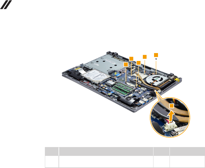
Figure 8. Removal steps of fan assembly and heat sink assembly (continued)
Lift the fan assembly and heat sink assembly in the direction shown by arrow 4.
Be careful not to damage the connector.
Z410
4
Z510/Z510 Touch
4
Attention: Do not handle the heat sink assembly roughly. Improper handling
can cause distortion or deformation and imperfect contact with components.
54
Z410/Z510/Z510 Touch Hardware Maintenance Manual
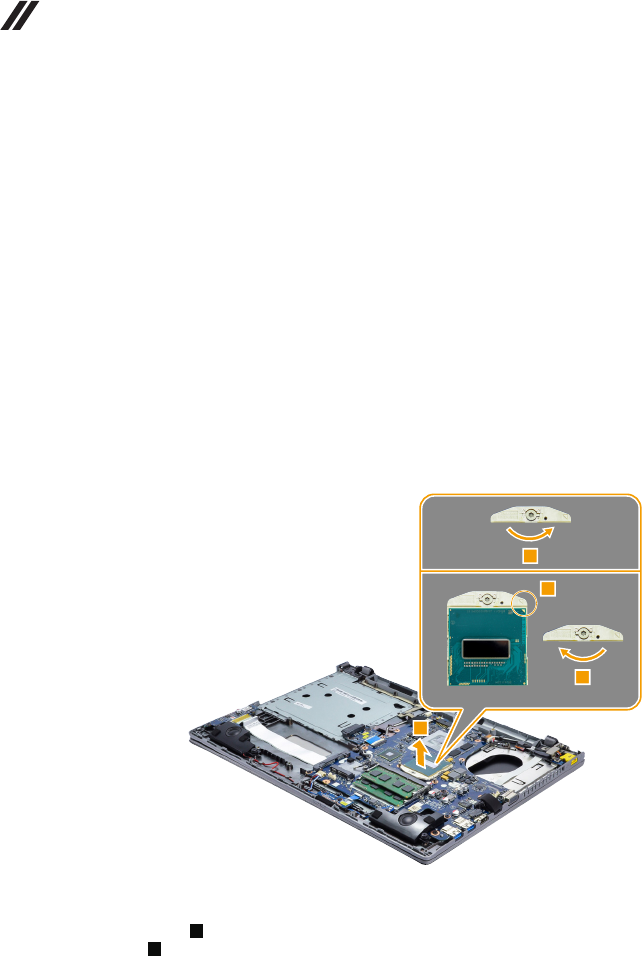
1090 CPU
For access, remove these FRUs in order:
• “1010 Keyboard” on page 33
• “1020 Optical drive” on page 37
• “1030 Base cover” on page 39
• “1040 Battery pack” on page 44
• “1050 Hard disk drive” on page 46
• “1060 PCI Express Mini Card for wireless LAN” on page 48
• “1080 Fan assembly and Heat Sink assembly” on page 51
Attention: CPU is extremely sensitive. When you service the CPU, avoid any
kind of rough handling.
Figure 9. Removal steps of CPU
Rotate the head of the screw in the direction shown by arrow 1 to release the
lock, then remove the CPU in the direction shown by arrow 2.
1
b
a
2
When installing: Place the CPU on the CPU socket in the direction shown by
arrow a, and then rotate the head of the screw in the direction shown by arrow
b to secure the CPU.
55
Lenovo Z410/Z510/Z510 Touch
1100 ODD board and LED board (Z510/Z510 Touch)
For access, remove these FRUs in order:
• “1010 Keyboard” on page 33
• “1020 Optical drive” on page 37
• “1030 Base cover” on page 39
• “1040 Battery pack” on page 44
• “1050 Hard disk drive” on page 46
• “1060 PCI Express Mini Card for wireless LAN” on page 48
• “1080 Fan assembly and Heat Sink assembly” on page 51
Figure 10. Removal steps of ODD board and LED board (Z510/Z510 Touch)
Detach the two FPC connectors in the direction shown by arrows 1 2.
Remove the screws 3 and 4.
4
4
3
3
1
2
1
2
Step Screw (quantity) Color Torque
3M2 × 2.5, at-head, nylok-coated (2) Black 1.85+/-0.15 kgf/cm
4M2 × 3, at-head, nylok-coated (2) Black 1.85+/-0.15 kgf/cm
56
Z410/Z510/Z510 Touch Hardware Maintenance Manual
Figure 10. Removal steps of ODD board and LED board (Z510/Z510 Touch)
(continued)
Remove the two boards in the direction shown by arrows 5.
5
5
When installing: Make sure that the two FPC connectors are attached rmly.
57
Lenovo Z410/Z510/Z510 Touch
1110 Speakers
For access, remove these FRUs in order:
• “1010 Keyboard” on page 33
• “1020 Optical drive” on page 37
• “1030 Base cover” on page 39
• “1040 Battery pack” on page 44
• “1050 Hard disk drive” on page 46
• “1060 PCI Express Mini Card for wireless LAN” on page 48
• “1080 Fan assembly and Heat Sink assembly” on page 51
• “1100 ODD board and LED board (Z510/Z510 Touch)” on page 55
Figure 11. Removal steps of speakers
Detach the speakers connector in the direction shown by arrow 1. Remove
the screws 2.
Z410
1
2
2
2
2
58
Z410/Z510/Z510 Touch Hardware Maintenance Manual
Figure 11. Removal steps of speakers (continued)
Z510/Z510 Touch
2
2
2
2
1
Step Screw (quantity) Color Torque
2M2 × 5.7+2, at-head, nylok-coated (4)
Speaker to Logic Upper
Black 1.85+/-0.15 kgf/cm
59
Lenovo Z410/Z510/Z510 Touch
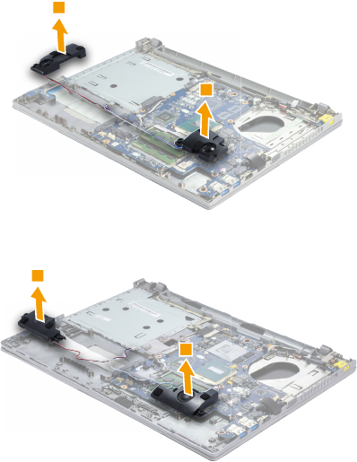
Figure 11. Removal steps of speakers (continued)
Remove the speakers 3.
Z410
3
3
Z510/Z510 Touch
3
3
When installing: Make sure that the speakers connector is attached rmly.
60
Z410/Z510/Z510 Touch Hardware Maintenance Manual
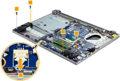
1120
System board
Important notices for handling the system board:
Whenhandlingthesystemboard,bearthefollowinginmind.
• Becarefulnottodropthesystemboardonabenchtopthathasahardsurface,
suchasmetal,wood,orcomposite.
• Avoidroughhandlingofanykind.
• Inthewholeprocess,makesurenottodroporstackthesystemboard.
• Ifyouputasystemboarddown,makesuretoputitonlyonapaddedsurfacesuch
asanESDmatorconductivecorrugatedmaterial.
For access, remove these FRUs in order:
• “1010 Keyboard” on page 33
• “1020 Optical drive” on page 37
• “1030 Base cover” on page 39
• “1040 Battery pack” on page 44
• “1050 Hard disk drive” on page 46
• “1060 PCI Express Mini Card for wireless LAN” on page 48
• “1080 Fan assembly and Heat Sink assembly” on page 51
• “1100 ODD board and LED board (Z510/Z510 Touch)” on page 55
• “1110 Speakers” on page 57
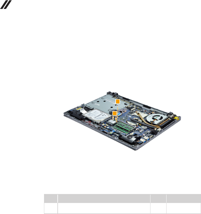
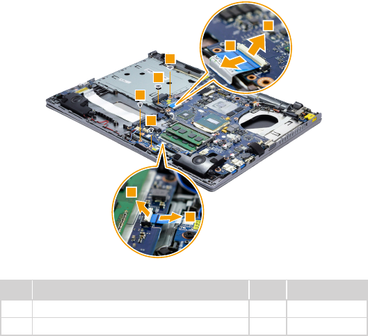
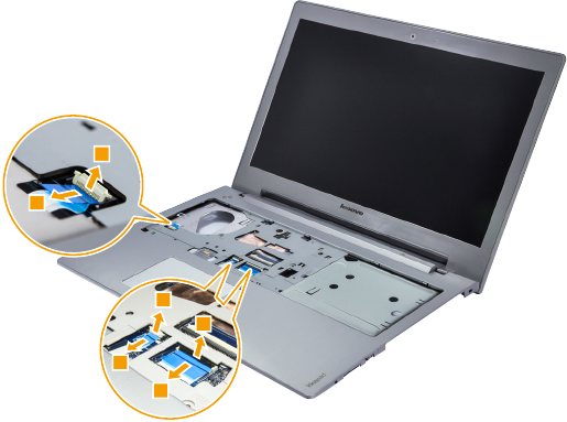
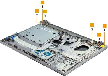
Figure 12. Removal steps of system board
Detach the three FPC connectors in the direction shown by arrows 1 2.
Z410
1
2
1
1
2
2
61
Lenovo Z410/Z510/Z510 Touch
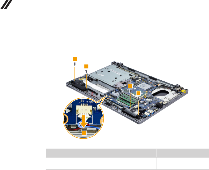
Figure 12. Removal steps of system board (continued)
Z510/Z510 Touch
1
2
1
1
2
2
62
Z410/Z510/Z510 Touch Hardware Maintenance Manual
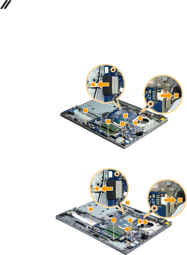
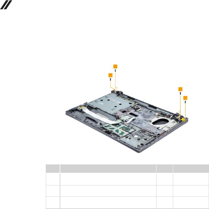
Figure 12. Removal steps of system board (continued)
Detach the connectors in the direction shown by arrows 3. Remove the screws
4, 5 and 6.
Z410
3
3
4
5
6
6
6
6
Z510
3
3
45
6
6
6
6
6
63
Lenovo Z410/Z510/Z510 Touch
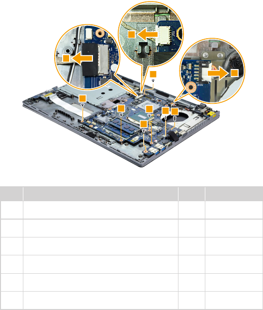
Figure 12. Removal steps of system board (continued)
Z510 Touch
3
3
3
6
6
6
6
645
Step Screw (quantity) Color Torque
4M2.5 × 6 mm, at-head, nylok-coated (1) (Z410)
RJ45 Cover to MB
Black 3.0+/-0.3 kgf/cm
4M2.0 × 4.9 mm, at-head, nylok-coated (1)
(Z510/Z510 Touch) RJ45 Cover to MB
Black 1.85+/-0.15 kgf/cm
5M2.0 × 4.9 mm, at-head, nylok-coated (1)
(Z410) RJ45 Cover to Logic Upper
Black 1.85+/-0.15 kgf/cm
5M2.5 × 6 mm, at-head, nylok-coated (1)
(Z510/Z510 Touch) RJ45 Cover to Logic Upper
Black 3.0+/-0.3 kgf/cm
6M2.5 × 3 mm, at-head, nylok-coated (4) (Z410)
MB to Logic Upper
Black 3.0+/-0.3 kgf/cm
6M2.5 × 3 mm, at-head, nylok-coated (5)
(Z510/Z510 Touch) MB to Logic Upper
Black 3.0+/-0.3 kgf/cm
When installing: Make sure that the connectors are attached rmly.
64
Z410/Z510/Z510 Touch Hardware Maintenance Manual
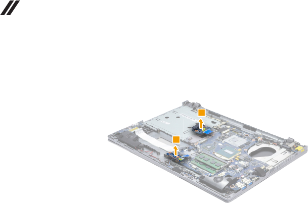
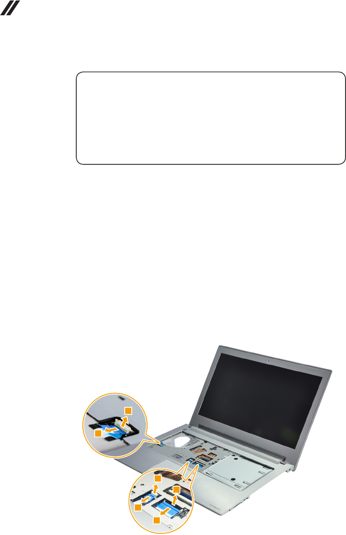
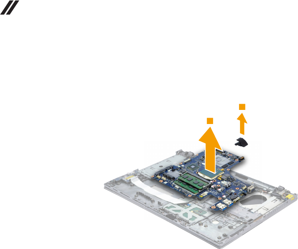
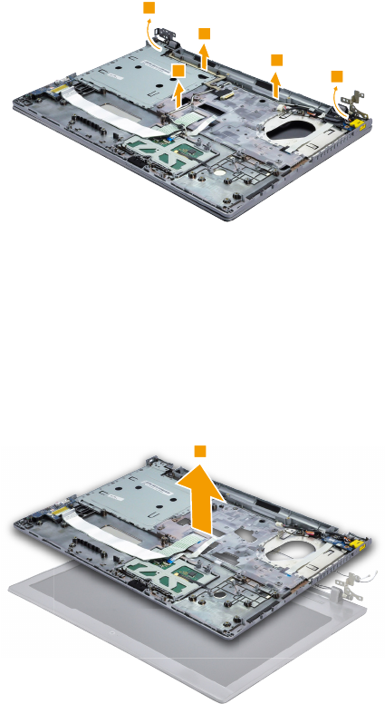
Figure 12. Removal steps of system board (continued)
Remove the RJ-45 door in the direction shown by arrow 7. Remove the
system board in the direction shown by arrow 8.
7
8
65
Lenovo Z410/Z510/Z510 Touch
1130 LCD unit
For access, remove these FRUs in order:
• “1010 Keyboard” on page 33
• “1020 Optical drive” on page 37
• “1030 Base cover” on page 39
• “1040 Battery pack” on page 44
• “1050 Hard disk drive” on page 46
• “1060 PCI Express Mini Card for wireless LAN” on page 48
• “1070 DIMM” on page 50
• “1080 Fan assembly and Heat Sink assembly” on page 51
• “1100 ODD board and LED board (Z510/Z510 Touch)” on page 55
• “1110 Speakers” on page 57
• “1120 System board” on page 60
Figure 13. Removal steps of LCD unit
Z410
Remove the screws 1 and 1’.
1
11
1
1
1’
66
Z410/Z510/Z510 Touch Hardware Maintenance Manual
Figure 13. Removal steps of LCD unit (continued)
Z510/Z510 Touch
Remove the screws 1.
1
1
1
1
Step Screw (quantity) Color Torque
1M2.5 × 6 mm, at-head, nylok-coated (5) (Z410)
LCD Ass'y to Logic Upper
Black 3.0+/-0.3 kgf/cm
1M2.5 × 6 mm, at-head, nylok-coated (6)
(Z510/Z510 Touch) LCD Ass'y to Logic Upper
Black 3.0+/-0.3 kgf/cm
1’M2 × 2 mm, at-head, nylok-coated (1) (Z410)
LCD Ass'y to Logic Upper
Black 1.85+/-0.15 kgf/cm
67
Lenovo Z410/Z510/Z510 Touch
Figure 13. Removal steps of LCD unit (continued)
Release the LCD cable from the cable guides in the direction shown by arrows
2. Then lift the LCD hinge in the direction shown by arrow 3.
2
3
3
2
2
When installing:
• Route the antenna cables along the cable guides. As you route the cables,
make sure that they are not subjected to any tension. Tension could cause
the cables to be damaged by the cable guides, or a wire to be broken.
• Make sure that the LCD connector is attached rmly and make sure that you
do not pinch the antenna cables when you attach the LCD assembly. Route
the LCD cable along the cable guides.
Remove the keyboard bezel from the LCD unit in the direction shown by arrows 5.
4
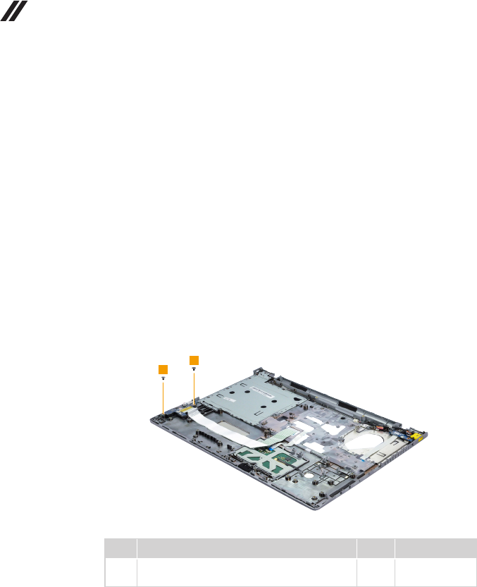
68
Z410/Z510/Z510 Touch Hardware Maintenance Manual
1140
Keyboard bezel
For access, remove these FRUs in order:
• “1010 Keyboard” on page 33
• “1020 Optical drive” on page 37
• “1030 Base cover” on page 39
• “1040 Battery pack” on page 44
• “1050 Hard disk drive” on page 46
• “1060 PCI Express Mini Card for wireless LAN” on page 48
• “1070 DIMM” on page 50
• “1080 Fan assembly and Heat Sink assembly” on page 51
• “1100 ODD board and LED board (Z510/Z510 Touch)” on page 55
• “1110 Speakers” on page 57
• “1120 System board” on page 60
• “1130 LCD unit” on page 65
Figure 14. Removal steps of keyboard bezel
Remove the screws 1.
1
1
Step Screw (quantity) Color Torque
1M2.5 × 3 mm, at-head, nylok-coated (2)
USB Board to Logic Upper
Black 3.0+/-0.3 kgf/cm
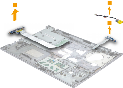
69
Lenovo Z410/Z510/Z510 Touch
Figure 14. Removal steps of keyboard bezel (continued)
Remove the power board, USB board and DC-in jack in the direction shown by
arrows 2.
2
2
2
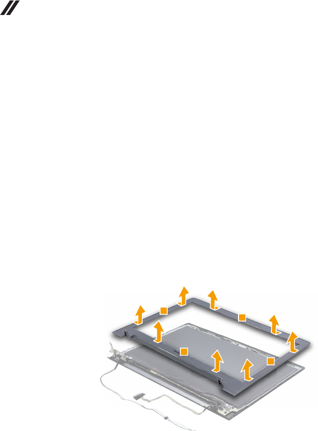
70
Z410/Z510/Z510 Touch Hardware Maintenance Manual
1150 LCD front bezel/LCD hinge cover
For access, remove these FRUs in order:
• “1010 Keyboard” on page 33
• “1020 Optical drive” on page 37
• “1030 Base cover” on page 39
• “1040 Battery pack” on page 44
• “1050 Hard disk drive” on page 46
• “1060 PCI Express Mini Card for wireless LAN” on page 48
• “1070 DIMM” on page 50
• “1080 Fan assembly and Heat Sink assembly” on page 51
• “1100 ODD board and LED board (Z510/Z510 Touch)” on page 55
• “1110 Speakers” on page 57
• “1120 System board” on page 60
• “1130 LCD unit” on page 65
• “1140 Keyboard bezel” on page 68
Figure 15. Removal steps of LCD front bezel/LCD hinge cover
Z410/Z510
Remove the LCD front bezel in the direction shown by arrows 1.
1
1
1
1
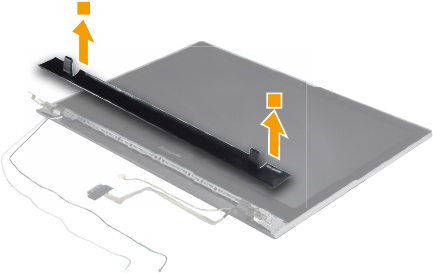
71
Lenovo Z410/Z510/Z510 Touch
Figure 15. Removal steps of LCD front bezel/LCD hinge cover (continued)
Z510 Touch
Remove the LCD front bezel in the direction shown by arrows 1.
1
1
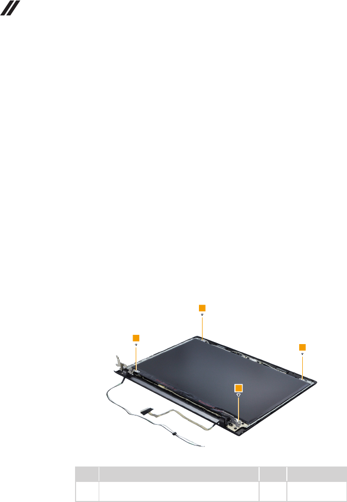
72
Z410/Z510/Z510 Touch Hardware Maintenance Manual
1160 LCD panel/LCD module
For access, remove these FRUs in order:
• “1010 Keyboard” on page 33
• “1020 Optical drive” on page 37
• “1030 Base cover” on page 39
• “1040 Battery pack” on page 44
• “1050 Hard disk drive” on page 46
• “1060 PCI Express Mini Card for wireless LAN” on page 48
• “1070 DIMM” on page 50
• “1080 Fan assembly and Heat Sink assembly” on page 51
• “1100 ODD board and LED board (Z510/Z510 Touch)” on page 55
• “1110 Speakers” on page 57
• “1120 System board” on page 60
• “1130 LCD unit” on page 65
• “1140 Keyboard bezel” on page 68
• “1150 LCD front bezel/LCD hinge cover” on page 70
Figure 16. Removal steps of LCD panel/LCD module
Z410/Z510
Remove the screws 1.
1
1
1
1
Step Screw (quantity) Color Torque
1M2 × 2.5 mm, at-head, nylok-coated (4)
LCD_PANEL to LCD COVER
Black 1.85+/-0.15 kgf/cm
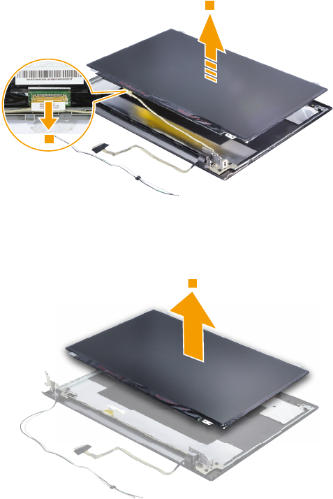
73
Lenovo Z410/Z510/Z510 Touch
Figure 16. Removal steps of LCD panel/LCD module (continued)
Lift the LCD panel a little 2. Peel off the adhesive tape and detach the
connector in the direction shown by arrow 3.
2
3
When installing: Make sure that the metal connector is attached rmly.
Remove the LCD panel 4.
4
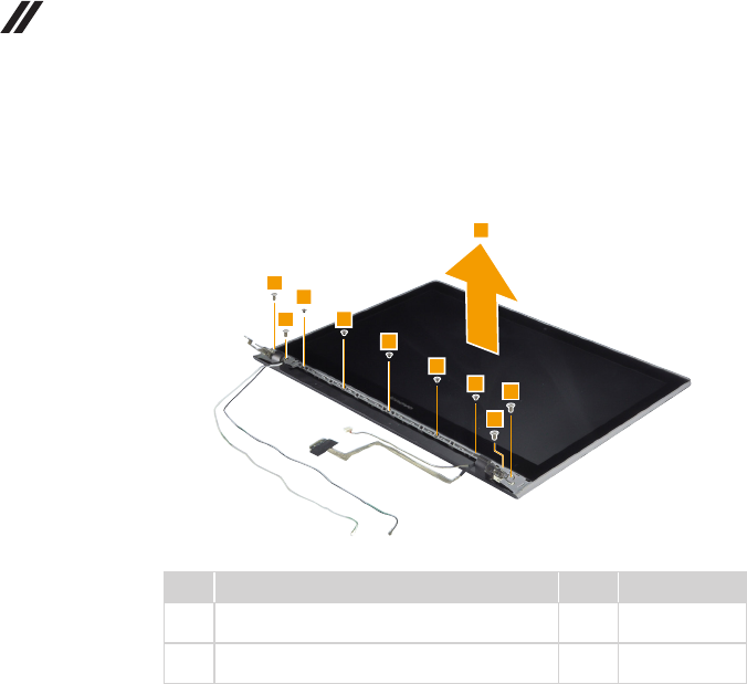
74
Z410/Z510/Z510 Touch Hardware Maintenance Manual
Figure 16. Removal steps of LCD panel/LCD module (continued)
Z510 Touch
Remove the screws 1 and 2, then remove the LCDl module 3.
1
1
1
1
2
2
2
2
2
3
Step Screw (quantity) Color Torque
1M2 × 2.5 mm, at-head, nylok-coated (4)
LCD_PANEL to LCD COVER
White 1.85+/-0.15 kgf/cm
2M2.5 × 5 mm, at-head, nylok-coated (5)
LCD_PANEL to LCD COVER
Black 3.0+/-0.3 kgf/cm
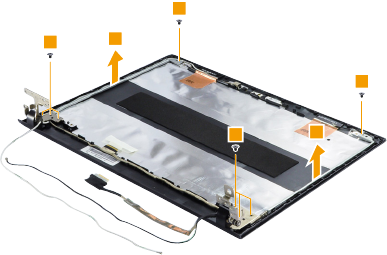
75
Lenovo Z410/Z510/Z510 Touch
1170 LCD Hinges
For access, remove these FRUs in order:
• “1010 Keyboard” on page 33
• “1020 Optical drive” on page 37
• “1030 Base cover” on page 39
• “1040 Battery pack” on page 44
• “1050 Hard disk drive” on page 46
• “1060 PCI Express Mini Card for wireless LAN” on page 48
• “1070 DIMM” on page 50
• “1080 Fan assembly and Heat Sink assembly” on page 51
• “1100 ODD board and LED board (Z510/Z510 Touch)” on page 55
• “1110 Speakers” on page 57
• “1120 System board” on page 60
• “1130 LCD unit” on page 65
• “1140 Keyboard bezel” on page 68
• “1150 LCD front bezel/LCD hinge cover” on page 70
• “1160 LCD panel/LCD module” on page 72
Figure 17. Removal steps of LCD hinges
Z410
Remove the screws 1 and 2. Then release the two hinges in the direction
shown by arrows 3.
2
2
1
1
3
3
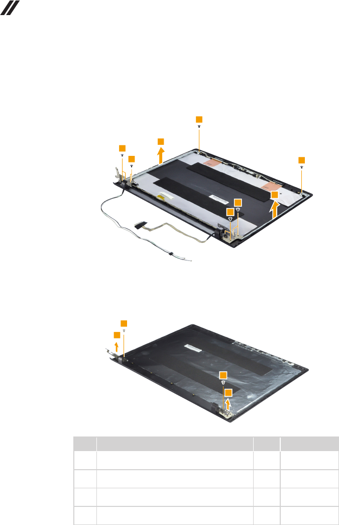
76
Z410/Z510/Z510 Touch Hardware Maintenance Manual
Figure 17. Removal steps of LCD hinges (continued)
Z510
Remove the screws 2. Then release the two hinges in the direction shown by
arrows 3.
2
2
2
2
2
2
3
3
Z510 Touch
Remove the screws 2. Then release the two hinges in the direction shown by
arrows 3.
2
2
3
3
Step Screw (quantity) Color Torque
1M2 × 2.5 mm, at-head, nylok-coated (2) (Z410)
Hinge L/R to LCD Cover
Black 1.85+/-0.15 kgf/cm
2M2.5 × 3 mm, at-head, nylok-coated (6) (Z410)
Hinge L/R to LCD Cover
Black 3.0+/-0.3 kgf/cm
2M2 × 3 mm, at-head, nylok-coated (10) (Z510)
Hinge L/R to LCD Cover
Black 1.85+/-0.15 kgf/cm
2M2.5 × 3 mm, at-head, nylok-coated (2)
(Z510 Touch) Hinge L/R to LCD Cover
White 3.0+/-0.3 kgf/cm
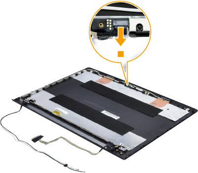
77
Lenovo Z410/Z510/Z510 Touch
1180 Integrated camera, LCD cable and antenna assembly
For access, remove these FRUs in order:
• “1010 Keyboard” on page 33
• “1020 Optical drive” on page 37
• “1030 Base cover” on page 39
• “1040 Battery pack” on page 44
• “1050 Hard disk drive” on page 46
• “1060 PCI Express Mini Card for wireless LAN” on page 48
• “1070 DIMM” on page 50
• “1080 Fan assembly and Heat Sink assembly” on page 51
• “1100 ODD board and LED board (Z510/Z510 Touch)” on page 55
• “1110 Speakers” on page 57
• “1120 System board” on page 60
• “1130 LCD unit” on page 65
• “1140 Keyboard bezel” on page 68
• “1150 LCD front bezel/LCD hinge cover” on page 70
• “1160 LCD panel/LCD module” on page 72
• “1170 LCD Hinges” on page 75
Figure 18. Removal steps of integrated camera, LCD cable and antenna
assembly
Z410/Z510
Note: The integrated camera is stuck on the top center of the LCD cover.
Detach the integrated camera connector in the direction shown by arow 1.
1
When installing: Stick the integrated camera to the top center of the LCD
cover and ajust the placement of it to make sure the connector is attached
rmly.

78
Z410/Z510/Z510 Touch Hardware Maintenance Manual
Figure 18. Removal steps of integrated camera, LCD cable and antenna
assembly (continued)
Remove the camera in the direction shown by arrow 2.
2
Remove the LCD cable and antenna assembly in the direction shown by arrows 3.
3
3
3
3
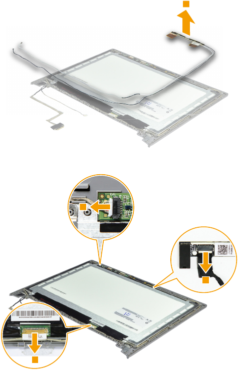
79
Lenovo Z410/Z510/Z510 Touch
Figure 18. Removal steps of integrated camera, LCD cable and antenna
assembly (continued)
Z510 Touch
Remove the antenna assembly in the direction shown by arrow 1.
1
Detach the connectors in the direction shown by arows 2.
2
2
2
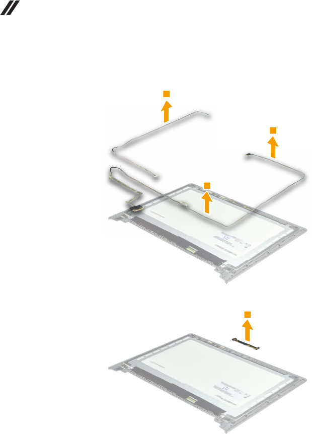
80
Z410/Z510/Z510 Touch Hardware Maintenance Manual
Figure 18. Removal steps of integrated camera, LCD cable and antenna
assembly (continued)
Remove the camera cable and LCD cable in the direction shown by arrows 3.
3
3
3
Remove the camera in the direction shown by arrow 4.
4
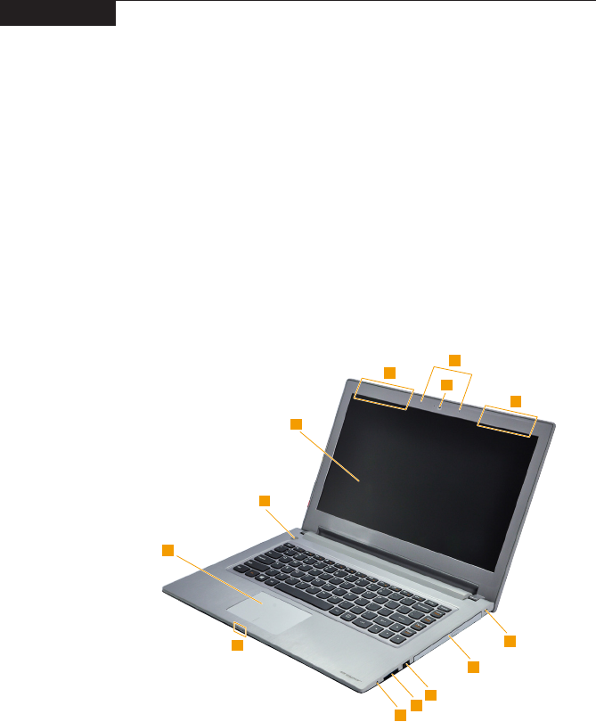
81
Lenovo Z410/Z510/Z510 Touch
Locations
Front view and right-side view
1 Integrated camera
2 Built-in microphone
3 Wireless LAN antennas
4 Computer display
5 Power button
6 Touchpad
7 System status indicators
Note: For the description of each indicator, see “Status indicators” on page 28.
8 Combo audio jack
9 Memory card slot
J USB port
K Optical drive
L Kensington slot
Z410
1
2
3
4
5
3
6
7
8
9
10
11
12
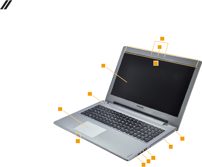
82
Z410/Z510/Z510 Touch Hardware Maintenance Manual
Z510/Z510 Touch
1
2
3
4
5
6
7
89
10
11
12
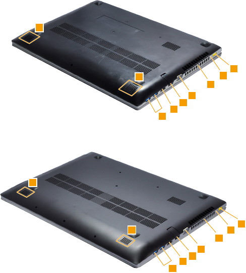
83
Lenovo Z410/Z510/Z510 Touch
Bottom and Left-side view
1 Speakers
2 USB port
3 HDMI port
4 RJ-45 port
5 VGA port
6 Fan louvers
7 Novo button
8 AC power adapter jack
Z410
1
2
3
1
4
5
6
7
8
Z510/Z510 Touch
1
2
3
1
4
5
6
7
8

84
Z410/Z510/Z510 Touch Hardware Maintenance Manual
Parts list
This section presents the following service parts:
• “Overall” on page 85
• “LCD FRUs” on page 93
• “Keyboard” on page 98
• “Miscellaneous parts” on page 104
• “AC adapters” on page 105
• “Screws” on page 105
• “Power cords” on page 106
Notes:
• EachFRUisavailableforalltypesormodels,unlessspecictypesormodels
arespecied.
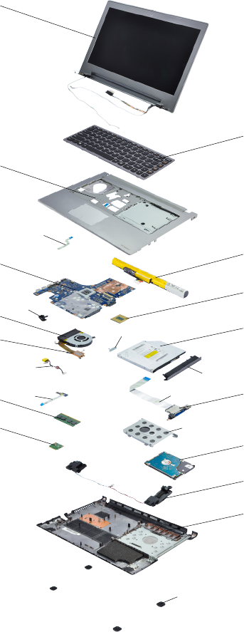
85
Lenovo Z410/Z510/Z510 Touch
Overall
Z410
1
3
f
e
h
g
a
i
c
b
5
7
11
12
8
2
4
6
9
10
13
14
15
d
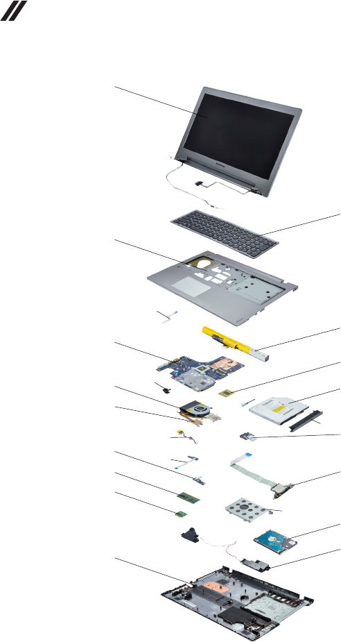
86
Z410/Z510/Z510 Touch Hardware Maintenance Manual
Z510/Z510 Touch
1
3
5
12
13
14
17
7
8
2
4
6
9
11
15
16
10
h
g
e
f
a
c
b

87
Lenovo Z410/Z510/Z510 Touch
Z410
Table 5. Parts list—Overall (Z410)
No. FRU FRU no. CRU ID.
a-i See “Miscellaneous parts” on page 104.
1 LCD unit (see “LCD FRUs” on page 93.)
2 Keyboard (see “Keyboard” on page 98.)
3 AILZA Upper Case 90203969
N
3 AILZA Upper Case for Erazer 90203970
4 Battery, 4S1P, 4cell,48Wh, Sanyo, Z400Z500 SY
L12S4K01 14.4V48Wh 4cellbty
121500113
4 Battery, 4S1P, 4cell,48Wh, Simplo, Zx10 SP/S
L12M4F02 15V48Wh 4cellbty
121500202
4 Battery, 4S1P, 4cell, 41.6Wh, Sanyo, Zx0 SY
L12S4E21 14.4V41.6Wh 4cellbty
121500121
4 Battery, 4S1P, 4cell, 41.6Wh,Simplo, Zx0 SP/L
L12M4E21 14.8V41.6Wh 4cellbty
121500123
5 AILZA MB UMA 37W 90004453
5 AILZA MB UMA 47W 90004454
5 AILZA MB N14P-GV2 1G 90004455
5 AILZA MB N14P-GV2 2G 90004456
5 AILZA MB W8S UMA 37W 90004457
5 AILZA MB W8S UMA 47W 90004458
5 AILZA MB W8S N14P-GV2 1G 90004459
5 AILZA MB W8S N14P-GV2 2G 90004460
5 AILZA MB W8P UMA 37W 90004461
5 AILZA MB W8P UMA 47W 90004462
5 AILZA MB W8P N14P-GV2 1G 90004463
5 AILZA MB W8P N14P-GV2 2G 90004464
6 Processor, Intel Haswell platform 35w, Intel I7-
4702MQ 2.2G 4cPGA CPU
102500541
6 Processor, Intel Haswell platform 35w, Intel I7-
4700MQ 2.4G 4cPGA CPU
102500540
7 AILZA FAN 90203964
8 AILZA Thermal DIS 37W 90203961
8 AILZA Thermal UMA 37W 90203962
8 AILZA Thermal UMA 37W 90203963
9 ODD, 9.5 Rambo Tray-in, HLDS GU70N 9.5 Rambo
ODD
25205807
9 ODD, 9.5 Rambo Tray-in, PLDS DU-8A5SH 9.5
Rambo ODD
25205806
9 ODD, 9.5 Rambo Tray-in, PSN UJ8DB Slim Tray
Rambo w/o bezel
25212030
9 ODD, 9.5 HLDS BU10N 9.5 BD Rambo ODD 25209260
9 ODD, 9.5 Panasonic UJ262 9.5 BD Rambo ODD 25209259
10 AILZA USB&Audio Board 90004452
88
Z410/Z510/Z510 Touch Hardware Maintenance Manual
No. FRU FRU no. CRU ID.
11 RAM, DDR3 1600 2GB, Samsung, M471B5773DH0-
YK0 2GB DDR3L 1600
11200502
N
11 RAM, DDR3 1600 2GB, SK hynix, HMT425S6AFR6A-
PB 2GB DDR3L 1600
11201299
11 RAM, DDR3 1600 2GB, Ramaxel,
RMT3170ED58F8W-1600
11201835
11 RAM, DDR3 1600 2GB, Micron, MT4KTF25664HZ-
1G6E1 2GB DDR3L 1600
11201967
11 RAM, DDR3L 1600 4GB, Samsung, M471B5173BH0-
YK0 4GB DDR3L 1600
11201966
11 RAM, DDR3L 1600 4GB, SK hynix,
HMT451S6AFR8A-PB 4GB DDR3L 1600
11201300
11 RAM, DDR3L 1600 4GB, Ramaxel,
RMT3170EB68F9W-1600 4GB DDR3L 1600
11201512
11 RAM, DDR3L 1600 4GB, Sharetronic,
SM321NQ08ICF 4GB DDR3L 1600
11201834
11 RAM, DDR3L 1600 4GB, Micron, MT8KTF51264HZ-
1G6J1 4GB DDR3L 1600
11201342
11 RAM, DDR3L 1600 8GB, Samsung, M471B1G73BH0-
YK0 8GB DDR3L 1600
11200504
11 RAM, DDR3L 1600 8GB, SK hynix,
HMT41GS6AFR8A-PB 8GB DDR3L 1600
11201301
11 RAM, DDR3L 1600 8GB, Sharetronic,
SM322NW08IAF 8GB DDR3L 1600
11201514
11 RAM, DDR3L 1600 8GB, Micron, MT16KTF1G64HZ-
1G6E1 8GB DDR3L 1600
11201304
12 WLAN, Intel 7260BN 2x2BN+BT PCIE HMC WLAN 20200412
12 WLAN, Cbt BCM94313HMG 1x1BGN HMC 20200102
12 WLAN, Liteon HB125 1x1BGN HMC 20200223
12 WLAN, Cbt BCM943142HM 1x1BGN+BT4.0 HMC 20200222
12 WLAN, Liteon WB225 1x1BGN+BT4.0 HMC 20200224
12 WLAN, Liteon WB335 1x1BGN+BT4.0 HMC 20200437
13 Hard disk drive, ST500LM012 6G 9.5mm 5.4K 500G
HDD
16200387
13 Hard disk drive, ST500LT012 6G 7mm 5.4K 500G
HDD
16200383
13 Hard disk drive, HTS545050A7E660 6G 7mm 5.4K
500G HDD
16200404
13 Hard disk drive, MQ01ABF050 6G 7mm 5.4K 500G
HDD
16200433
13 Hard disk drive, WD5000LPCX-24C6HT0 6G 7mm
5.4K 500G HDD
16200395
Table 5. Parts list—Overall (Z410) (continued)

89
Lenovo Z410/Z510/Z510 Touch
Table 5. Parts list—Overall (Z410) (continued)
No. FRU FRU no. CRU ID.
13 Hard disk drive, ST1000LM024 6G 9.5mm 5.4K 1T
HDD
16200385
N
13 Hard disk drive, HTS541010A9E660 6G 9.5mm 5.4K
1T HDD
16200400
13 Hard disk drive, TSB MQ01ABD100 6G 9.5mm 5.4K
1T HDD
16200429
13 Hard disk drive, WD10JPCX-24UE4T0 6G 9.5mm
5.4K 1T HDD
16200393
13 Hard disk drive, ST1000LM014 6G 9.5mm 1T SSHD 16200389
13 Hard disk drive, ST500LM000 6G 7mm 500G SSHD 16200391
14 AILZA Speaker L+R 90203976
15 AILZA Lower Case Brown 90203977
15 AILZA Lower Case White 90203978
— AC adapter (see “AC adapters” on page 105 ).

90
Z410/Z510/Z510 Touch Hardware Maintenance Manual
Z510/Z510 Touch
Table 6. Parts list—Overall (Z510/Z510 Touch)
No. FRU FRU no. CRU ID.
a-h See “Miscellaneous parts” on page 104.
1 LCD unit (see “LCD FRUs” on page 93.)
2 Keyboard (see “Keyboard” on page 98.)
3 AILZB Upper Case 90203995
N
3 AILZB Upper Case for Erazer 90203996
4 Battery, 4S1P, 4cell, 48Wh, Sanyo, Z400Z500 SY
L12S4K01 14.4V48Wh 4cellbty
121500113
4 Battery, 4S1P, 4cell, 48Wh, Simplo, Zx10 SP/S
L12M4F02 15V48Wh 4cellbty
121500202
4 Battery, 4S1P, 4cell, 41.6Wh, Sanyo, Zx0 SY
L12S4E21 14.4V41.6Wh 4cellbty
121500121
4 Battery, 4S1P, 4cell, 41.6Wh, Simplo, Zx0 SP/L
L12M4E21 14.8V41.6Wh 4cellbty
121500123
5 AILZB MB UMA 37W 90004472
5 AILZB MB UMA 47W 90004473
5 AILZB MB N14P-GV2 1G 90004474
5 AILZB MB N14P-GV2 2G 90004475
5 AILZB MB W8S UMA 37W 90004476
5 AILZB MB W8S UMA 47W 90004477
5 AILZB MB W8S N14P-GV2 1G 90004478
5 AILZB MB W8S N14P-GV2 2G 90004479
5 AILZB MB W8P UMA 37W 90004480
5 AILZB MB W8P UMA 47W 90004481
5 AILZB MB W8P N14P-GV2 1G 90004482
5 AILZB MB W8P N14P-GV2 2G 90004483
5 AILZC MB UMA 37W 90004867
5 AILZC MB UMA 47W 90004868
5 AILZC MB DIS 1G 90004869
5 AILZC MB DIS 2G 90004870
5 AILZC MB W8S UMA 37W 90004871
5 AILZC MB W8S UMA 47W 90004872
5 AILZC MB W8S DIS 1G 90004873
5 AILZC MB W8S DIS 2G 90004874
5 AILZC MB W8P UMA 37W 90004875
5 AILZC MB W8P UMA 47W 90004876
5 AILZC MB W8P DIS 1G 90004877
5 AILZC MB W8P DIS 2G 90004878
6 Processor, Intel Haswell platform 35w, Intel I7-
4702MQ 2.2G 4cPGA CPU
102500541
6 Processor, Intel Haswell platform 35w, Intel I7-
4700MQ 2.4G 4cPGA CPU
102500540
7 AILZA FAN 90203964
8 AILZA Thermal DIS 37W 90203961
8 AILZA Thermal UMA 37W 90203962

91
Lenovo Z410/Z510/Z510 Touch
Table 6. Parts list—Overall (Z510/Z510 Touch) (continued)
No. FRU FRU no. CRU ID.
8 AILZA Thermal UMA 47W 90203963
N
9 ODD, 9.5 Rambo Tray-in, HLDS GU70N 9.5 Rambo
ODD
25205807
9 ODD, 9.5 Rambo Tray-in, PLDS DU-8A5SH 9.5
Rambo ODD
25205806
9 ODD, 9.5 Rambo Tray-in, PSN UJ8DB Slim Tray
Rambo w/o bezel
25212030
9 ODD, 9.5 Blueray Rambo, HLDS BU10N 9.5 BD
Rambo ODD
25209260
9 ODD, 9.5 Blueray Rambo, Panasonic UJ262 9.5 BD
Rambo ODD
25209259
10 AILZB ODD Board W/BL 90004470
10 AILZB ODD Board WO/BL 90004471
11 AILZB USB&Audio Board 90004468
12 AILZB LED Board 90004469
13 RAM, DDR3L 1600 2GB, Samsung, SS
M471B5773DH0-YK0 DDR3L 1600 2GB
11200502
13 RAM, DDR3L 1600 2GB, SK hynix,
HMT425S6AFR6A-PB 2GB DDR3L 1600
11201299
13 RAM, DDR3L 1600 2GB, Ramaxel,
RMT3170ED58F8W-1600
11201835
13 RAM, DDR3L 1600 2GB, Micron, MT4KTF25664HZ-
1G6E1 2GB DDR3L 1600
11201967
13 RAM, DDR3L 1600 4GB, Samsung, M471B5173BH0-
YK0 4GB DDR3L 1600
11201966
13 RAM, DDR3L 1600 4GB, SK hynix,
HMT451S6AFR8A-PB 4GB DDR3L 1600
11201300
13 RAM, DDR3L 1600 4GB, Ramaxel,
RMT3170EB68F9W-1600 4GB DDR3L 1600
11201512
13 RAM, DDR3L 1600 4GB, Sharetronic,
SM321NQ08ICF 4GB DDR3L 1600
11201834
13 RAM, DDR3L 1600 4GB, Micron, MT8KTF51264HZ-
1G6J1 4GB DDR3L 1600
11201342
13 RAM, DDR3L 1600 8GB, Samsung, M471B1G73BH0-
YK0 8GB DDR3L 1600
11200504
13 RAM, DDR3L 1600 8GB, SK hynix,
HMT41GS6AFR8A-PB 8GB DDR3L 1600
11201301
13 RAM, DDR3L 1600 8GB, Sharetronic
SM322NW08IAF 8GB DDR3L 1600
11201514
13 RAM, DDR3L 1600 8GB, Micron, MT16KTF1G64HZ-
1G6E1 8GB DDR3L 1600
11201304
14 WLAN, WiFi 2x2 BGN+BT4.0, Intel, 7260BN
2x2BN+BT PCIE HMC WLAN
20200412
14 WLAN, WiFi 1x1 BGN Cbt BCM94313HMG 1x1BGN
HMC
20200102
14 WLAN, WiFi 1x1 BG Liteon HB125 1x1BGN HMC 20200223

92
Z410/Z510/Z510 Touch Hardware Maintenance Manual
No. FRU FRU no. CRU ID.
14 WLAN, WiFi 1x1 BGN+BT4.0 Cbt BCM943142HM
1x1BGN+BT4.0 HMC
20200222
N
14 WLAN, WiFi 1x1 BGN+BT4.0 Liteon WB225
1x1BGN+BT4.0 HMC
20200224
14 WLAN, WiFi 1x1 BGN+BT4.0 Liteon WB335
1x1BGN+BT4.0 HMC
20200437
15 HDD/SSD 500G 5400rpm ST500LM012 6G 9.5mm
5.4K 500G HDD
16200387
15 HDD/SSD 500G 5400rpm ST500LT012 6G 7mm 5.4K
500G HDD
16200383
15 HDD/SSD 500G 5400rpm HTS545050A7E660 6G
7mm 5.4K 500G HDD
16200404
15 HDD/SSD 500G 5400rpm MQ01ABF050 6G 7mm
5.4K 500G HDD
16200433
15 HDD/SSD 500G 5400rpm WD5000LPCX-24C6HT0
6G 7mm 5.4K 500G HDD
16200395
15 HDD/SSD 1TB 5400rpm ST1000LM024 6G 9.5mm
5.4K 1T HDD
16200385
15 HDD/SSD 1TB 5400rpm HTS541010A9E660 6G
9.5mm 5.4K 1T HDD
16200400
15 HDD/SSD 1TB 5400rpm TSB MQ01ABD100 6G
9.5mm 5.4K 1T HDD
16200429
15 HDD/SSD 1TB 5400rpm WD10JPCX-24UE4T0 6G
9.5mm 5.4K 1T HDD
16200393
15 HDD/SSD 1T Hybrid ST1000LM014 6G 9.5mm 1T
SSHD
16200389
15 HDD/SSD 500G Hybrid ST500LM000 6G 7mm 500G
SSHD
16200391
16 AILZB Speaker L+R 90204000
17 AILZB Lower Case Brown 90204001
17 AILZB Lower Case White 90204002
— AC adapter (see “AC adapters” on page 105 ).
Table 6. Parts list—Overall (Z510/Z510 Touch) (continued)
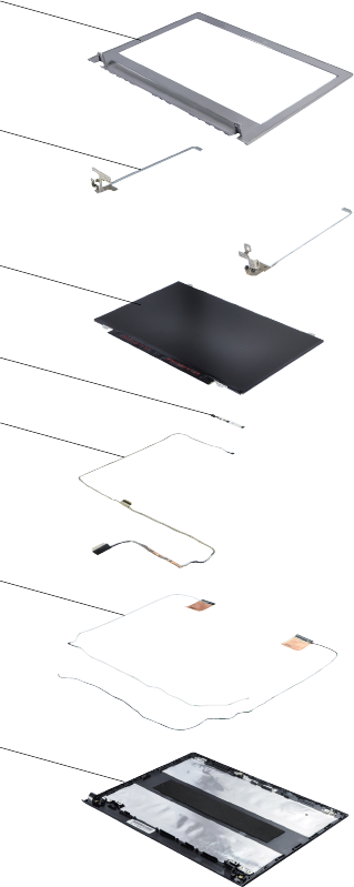
93
Lenovo Z410/Z510/Z510 Touch
LCD FRUs
In Lenovo Z410/Z510/Z510 Touch, there are following types of LCDs.
• “14-in. HD TFT”
1
2
3
5
6
7
4
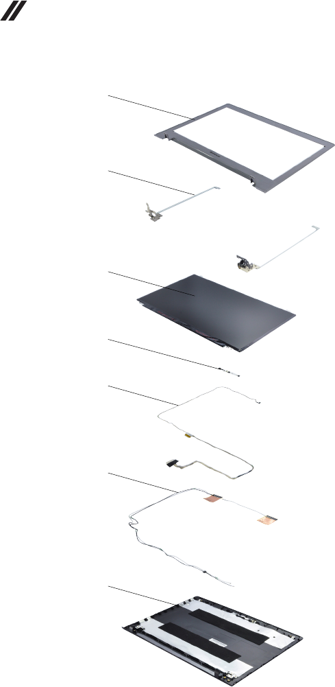
94
Z410/Z510/Z510 Touch Hardware Maintenance Manual
• “15.6-in. HD TFT”
1
2
3
5
6
7
4
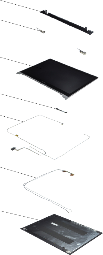
95
Lenovo Z410/Z510/Z510 Touch
• “15.6-in. Touch HD TFT”
1
2
3
5
7
6
4

96
Z410/Z510/Z510 Touch Hardware Maintenance Manual
14-in. HD TFT
Table 7. Parts list—14-in. HD TFT
No. FRU FRU no. CRU ID.
1 AILZA LCD Bezel 90203979
N
2 AILZA Hinge W/LCD Bracket 90203980
3 Panel, LGD LP140WH2-TPT1 HD AG F LED1 NB LCD 18200926
3Panel, AUO B140XTN03.3 3A HD AG F LED1 NB LCD 18200925
3 Panel, SDC LTN140AT30-401 HD AG F LED1 NB LCD 18200927
3 Panel, CMI N140BGE-E33 HD AG F LED1 NB LCD 18200928
3 Panel, AUO B140RTN02.3 1A HD+ AG F LED1 NB
LCD
18200932
3 Panel, LGD LP140WD2 TPB1 HD+ AG F LED1 NB
LCD
18200933
3 Panel, CMI N140FGE-E32 HD+ AG F LED1 NB LCD 18201073
4 AILZA Camera 1M 90004465
4 AILZA Camera 0.3M 90004466
5 AILZA EDP Cable 90203981
6AILZA Antenna 90203982
7 AILZA LCD Cover Brown 90203983
7 AILZA LCD Cover White 90203984

97
Lenovo Z410/Z510/Z510 Touch
15.6-in. HD TFT
Table 8. Parts list—15.6-in. HD TFT
No. FRU FRU no. CRU ID.
1 AILZB LCD Bezel 90204003
N
2 AILZB Hinge W/LCD Bracket 90204004
3Panel, HD-AG eDP1.2 3.2t,AUO B156XTN03.5 1A HD
AG S LED1 LCD
18201045
3 Panel, HD-AG eDP1.2 3.2t,LGD LP156WHU TPB1 HD
AG S LED1 LCD
18201046
3 Panel, HD-AG eDP1.2 3.2t,CMI N156BGE-EA1 HD AG
S LED1 NB LCD
18201074
3 Panel, HD-AG eDP1.2 3.2t,SDC LTN156AT33 401 HD
AG S LED1 NB LCD
18201047
3 Panel, FHD-S-AG eDP1.2 3.2t,AUO B156HTN03.4 1A
FHD AG S LED1 NB LCD
18201064
3 Panel, FHD-S-AG eDP1.2 3.2t,CMI N156HGE-EA1
FHD AG S LED1 NB LCD
18201065
4 AILZA Camera 1M 90004465
4 AILZA Camera 0.3M 90004466
5 AILZB EDP Cable 90204005
6AILZB Antenna 90204006
7 AILZB LCD Cover Brown 90204007
7 AILZB LCD Cover White 90204008
15.6-in. Touch HD TFT
Table 9. Parts list—15.6-in. Touch HD TFT
No. FRU FRU no. CRU ID.
1 AILZC Hinge Cover 90204287
N
2 AILZC Hinge 90204288
3 AILZC LCD Module HD AUO+LGD 90400224
3 AILZC LCD Module HD AUO+CMI 90400225
3 AILZC LCD Module HD AUO+SDC 90400226
3 AILZC LCD Module HD AUO+AUO 90400227
3 AILZC LCD Module FHD AUO+CMI 90400228
3 AILZC LCD Module FHD AUO+AUO 90400229
4 AILZC Camera 1M 90004879
5 AILZC LCD Cable 90204289
5 AILZC LCD touch Cable 90204290
6AILZC Antenna 90204291
7 AILZC LCD Cover 90204292
98
Z410/Z510/Z510 Touch Hardware Maintenance Manual
Keyboard
Z410
Table 10. Parts list—Keyboard (Z410)
Language P/N CRU ID.
Z410
Chicony
English 25211110
**
U.K. English 25211111
Italian 25211112
Spanish 25211113
Turkish 25211114
Thai 25211115
Portuguese 25211116
Latin 25211117
Canadian Bilingual (En+Fr) 25211118
Korean 25211119
Traditional Chinese 25211120
Russian 25211121
French 25211122
German 25211123
Arabic 25211124
Brazilian 25211125
Japanese 25211126
Dutch 25211127
Greek 25211128
Hebrew 25211129
Hungarian 25211130
Nordic 25211131
Belgian 25211132
Icelandic 25211133
Slovenian 25211134
Swiss 25211135
US international 25211136
Czech&Slovak 25211137
Bulgarian 25211138
Indic 25211139
Sunrex
English 25211140
U.K. English 25211141
Italian 25211142
Spanish 25211143
Turkish 25211144
Thai 25211145
Portuguese 25211146
Latin 25211147
Canadian Bilingual (En+Fr) 25211148
Korean 25211149
Traditional Chinese 25211150
Russian 25211151
French 25211152
German 25211153

99
Lenovo Z410/Z510/Z510 Touch
Language P/N CRU ID.
Z410
(continued)
Sunrex
(continued)
Arabic 25211154
**
Brazilian 25211155
Dutch 25211157
Greek 25211158
Hebrew 25211159
Hungarian 25211160
Four Nordic countries 25211161
Belgian 25211162
Icelandic 25211163
Slovenian 25211164
Swiss 25211165
International English 25211166
Czechoslovakian 25211167
Bulgarian 25211168
Indian 25211169
Darfon
U.S. English 25211170
U.K. English 25211171
Italian 25211172
Spanish 25211173
Turkish 25211174
Thai 25211175
Portuguese 25211176
Latin 25211177
Canadian English&French 25211178
Korean 25211179
Traditional Chinese 25211180
Russian 25211181
French 25211182
German 25211183
Arabic 25211184
Brazilian 25211185
Japanese 25211186
Dutch 25211187
Greek 25211188
Hebrew 25211189
Hungarian 25211190
Four Nordic countries 25211191
Belgian 25211192
Icelandic 25211193
Slovenian 25211194
Swiss 25211195
International English 25211196
Czechoslovakian 25211197
Bulgarian 25211198
Indian 25211199
Table 10. Parts list—Keyboard (Z410) (continued)

100
Z410/Z510/Z510 Touch Hardware Maintenance Manual
Z510/Z510 Touch
Table 11. Parts list—Keyboard (Z510/Z510 Touch)
Language P/N CRU ID.
Z510/Z510
Touch
Chicony
English 25213591
**
U.K. English 25213592
Italian 25213593
Spanish 25213594
Turkish 25213595
Thai 25213596
Portuguese 25213597
Latin 25213598
Canadian Bilingual (En+Fr) 25213599
Korean 25213600
Traditional Chinese 25213601
Russian 25213602
French 25213603
German 25213604
Arabic 25213605
Brazilian 25213606
Japanese 25213607
Dutch 25213608
Greek 25213609
Hebrew 25213610
Hungarian 25213611
Nordic 25213612
Belgian 25213613
Icelandic 25213614
Slovenian 25213615
Swiss 25213616
US international 25213617
Czech&Slovak 25213618
Bulgarian 25213619
Indic 25213620
Chicony
Backlight KB
English 25213721
U.K. English 25213722
English 25213723
Italian 25213724
Spanish 25213725
Turkish 25213726
Thai 25213727
Portuguese 25213728
Latin 25213729
Canadian Bilingual (En+Fr) 25213730
Korean 25213731
Traditional Chinese 25213732
Russian 25213733
French 25213734
German 25213735

101
Lenovo Z410/Z510/Z510 Touch
Language P/N CRU ID.
Z510/Z510
Touch
(continued)
Chicony
Backlight KB
(continued)
Arabic 25213736
**
Brazilian 25213737
Japanese 25213738
Dutch 25213739
Greek 25213740
Hebrew 25213741
Hungarian 25213742
Nordic 25213743
Belgian 25213744
Icelandic 25213745
Slovenian 25213746
Swiss 25213747
US international 25213748
Czech&Slovak 25213749
Bulgarian 25213750
Indic 25213751
Sunrex Normal
KB
English 25213621
U.K. English 25213622
Italian 25213623
Spanish 25213624
Turkish 25213625
Thai 25213626
Portuguese 25213627
Latin 25213628
Canadian Bilingual (En+Fr) 25213629
Korean 25213630
Traditional Chinese 25213631
Russian 25213632
French 25213633
German 25213634
Arabic 25213635
Brazilian 25213636
Dutch 25213638
Greek 25213639
Hebrew 25213640
Hungarian 25213641
Nordic 25213642
Belgian 25213643
Icelandic 25213644
Slovenian 25213645
Swiss 25213646
US international 25213647
Czech&Slovak 25213648
Bulgarian 25213649
Indic 25213650
Table 11. Parts list—Keyboard (Z510/Z510 Touch) (continued)

102
Z410/Z510/Z510 Touch Hardware Maintenance Manual
Language P/N CRU ID.
Z510/Z510
Touch
(continued)
Sunrex
Backlight KB
English 25213752
**
U.K. English 25213753
English 25213754
Italian 25213755
Spanish 25213756
Turkish 25213757
Thai 25213758
Portuguese 25213759
Latin 25213760
Canadian Bilingual (En+Fr) 25213761
Korean 25213762
Traditional Chinese 25213763
Russian 25213764
French 25213765
German 25213766
Arabic 25213767
Brazilian 25213768
Dutch 25213770
Greek 25213771
Hebrew 25213772
Hungarian 25213773
Nordic 25213774
Belgian 25213775
Icelandic 25213776
Slovenian 25213777
Swiss 25213778
US international 25213779
Czech&Slovak 25213780
Bulgarian 25213781
Indic 25213782
Darfon Normal
KB
English 25213651
U.K. English 25213652
Italian 25213653
Spanish 25213654
Turkish 25213655
Thai 25213656
Portuguese 25213657
Latin 25213658
Canadian Bilingual (En+Fr) 25213659
Korean 25213660
Traditional Chinese 25213661
Russian 25213662
French 25213663
German 25213664
Arabic 25213665
Brazilian 25213666
Table 11. Parts list—Keyboard (Z510/Z510 Touch) (continued)

103
Lenovo Z410/Z510/Z510 Touch
Language P/N CRU ID.
Z510/Z510
Touch
(continued)
Darfon Normal
KB
(continued)
Japanese 25213667
**
Dutch 25213668
Greek 25213669
Hebrew 25213670
Hungarian 25213671
Nordic 25213672
Belgian 25213673
Icelandic 25213674
Slovenian 25213675
Swiss 25213676
US international 25213677
Czech&Slovak 25213678
Bulgarian 25213679
Indic 25213680
Darfon Backlight
KB
English 25213681
U.K. English 25213682
Italian 25213683
Spanish 25213684
Turkish 25213685
Thai 25213686
Portuguese 25213687
Latin 25213688
Canadian Bilingual (En+Fr) 25213689
Korean 25213690
Traditional Chinese 25213691
Russian 25213692
French 25213693
German 25213694
Arabic 25213695
Brazilian 25213696
Japanese 25213697
Dutch 25213698
Greek 25213699
Hebrew 25213700
Hungarian 25213701
Nordic 25213702
Belgian 25213703
Icelandic 25213704
Slovenian 25213705
Swiss 25213706
US international 25213707
Czech&Slovak 25213708
Bulgarian 25213709
Indic 25213710
English 25213783
Table 11. Parts list—Keyboard (Z510/Z510 Touch) (continued)

104
Z410/Z510/Z510 Touch Hardware Maintenance Manual
Miscellaneous parts
Z410
Table 12. Parts list—Miscellaneous parts (Z410)
FRU P/N CRU ID.
System miscellaneous parts:
• (
a
) AILZA ODD Bracket
• (
b
) AILZA ODD Bezel Rambo Brown
• (
b
) AILZA ODD Bezel Rambo White
• (
b
) AILZA ODD Bezel BD Brown
• (
b
) AILZA ODD Bezel BD White
• (
c
) AILZA HDD Bracket
• (
d
) AILZA Rubber Brown
• (
d
) AILZA Rubber White
• (
e
) AILZA RG45 Door Brown
• (
e
) AILZA RG45 Door White
90203960
90203956
90203957
90203958
90203959
90203955
90203965
90203966
90203967
90203968 N
Cable miscellaneous parts:
• (
f
) AILZA TP Cable
• (
g
) AILZA DC-IN Cable
• (
h
) AILZA Power Board W/Cable
• (
i
) AILZA USB Cable
Note: Italicized letters in parentheses are references to the
exploded view in “Overall” on page 85 .
90203971
90203973
90004451
90203973
Z510/Z510 Touch
Table 13. Parts list—Miscellaneous parts (Z510/Z510 Touch)
FRU P/N CRU ID.
System miscellaneous parts:
• (
a
) AILZA ODD Bracket
• (
b
) AILZA ODD Bezel Rambo Brown
• (
b
) AILZA ODD Bezel Rambo White
• (
b
) AILZA ODD Bezel BD Brown
• (
b
) AILZA ODD Bezel BD White
• (
c
) AILZA HDD Bracket
• (
e
) AILZB RG45 Door Brown
• (
e
) AILZB RG45 Door Brown
90203960
90203956
90203957
90203958
90203959
90203955
90203993
90203994 N
Cable miscellaneous parts:
• (
f
) AILZA TP Cable
• (
g
) AILZA DC-IN Cable
• (
h
) AILZA Power Board W/Cable
Note: Italicized letters in parentheses are references to the
exploded view in “Overall” on page 85 .
90203997
90203974
90004467

105
Lenovo Z410/Z510/Z510 Touch
AC adapters
Table 14. Parts list—3-pin AC adapters
FRU P/N CRU ID.
65W, Delta ADLX65NDC3A 20V3.25A adapter 36200249
*
65W, Liteon ADLX65NLC3A 20V3.25A adapter 36200251
65W, Chicony ADLX65NCC3A 20V3.25A adapter 36200253
65W, Delta ADLX65NDC3B 20V3.25A adapter PPB 36200301
65W, Liteon ADLX65NLC3B 20V3.25A adapter PPB 36200303
90W, Delta ADLX90NDC3A 20V4.5A adapter 36200250
90W, Liteon ADLX90NLC3A 20V4.5A adapter 36200252
90W, Chicony ADLX90NCC3A 20V4.5A adapter 36200254
Screws
Table 15. Parts list—screws
FRU P/N CRU ID.
AILZA Screw M M 2.5D 5.7+2L K 6.0D 90203985
N
AILZA Screw M M 3.0D 3.0L K 4.9D 90203986
AILZA Screw M M 2 2.0D 2L K 7D 90203987
AILZA Screw M M 2.0D 2.5L K 5D 90203988
AILZA Screw M M 2D 1.5+3.4L K 3.5D 1T 90203989
AILZA Screw M M 2.5D 3.0L K 5.5D 90203990
AILZA Screw M M 2.5D 6.0L K 4.6D 90203991
AILZA Screw M M 2D 7.4+4.6L K 3.5D 1T(Z410) 90203992
AILZC SCREW M M 2.5D 4.5L K 5.5D(Z510/Z510 Touch) 90204293
AILZC SCREW M M 2.5D 3.5L K 5.3D(Z510/Z510 Touch) 90204294
AILZC SCREW M M 2D 2.5L K 4D 0.5T(Z510/Z510 Touch) 90204295

106
Z410/Z510/Z510 Touch Hardware Maintenance Manual
Power cords
A Lenovo power cord for a specic country or region is usually available only in
that country or region:
Table 16. Parts list—3-pin power cords
Region P/N CRU ID.
CCC
• LINETEK PC323+RVV300/300+LS15 1m
145000600
*
Argentina
• LINETEK LS15+H03VV-F+LP39 1m
145000599
Danmark
• LINETEK LS15+H03VV-F+LP-38 1m
145000598
Switzerland
• LINETEK LS15+H03VV-F+LP-37 1m
145000597
Brazil
• LINETEK LS15 H03VV-F LP26A 1m
145000596
Israel
• LINETEK LS15+H03VV-F+LP-41 1m
145000595
UL
• LINETEK LP-30B + SPT-2 + LS15 1m
145000594
UK
• LINETEK LP-61L+ H03VV-F+ LS15 1m
145000593
Indian
• LINETEK PE-361+ H05VV-F+ LS15 1m
145000592
Italy
• LINETEK LS15+H03VV-F+PE-336 1m
145000591
Korea
• LINETEK LS15+H05VV-F+LP-E04A 1m
145000590
Australia
• LINETEK LS15+H03VV-F+LP-23A 1m
145000589
Taiwan
• LINETEK LS15+VCTF+LP-53 1m
145000588
Japan
• LINETEK LS15+VCTF+LP-54 1m
145000587
Africa
• LINETEK LS15+H03VV-F+PE-364 1m
145000586
CE
• LINETEK LP-34+H03VV-F + LS15 1m
145000585
CCC
• Longwell LSG-31+RVV300/300+LS-18 1m
145000568
Argentina
• Longwell LP-24+H03VV-F+LS-18 1m
145000567
Danmark
• Longwell LP-40+H03VV-F+LS-18 1m
145000566
Switzerland
• Longwell LP-37+H03VV-F+LS-18 1m
145000565

107
Lenovo Z410/Z510/Z510 Touch
Region P/N CRU ID.
Brazil
• Longwell LP-46+H03VV-F+LS-18 1m
145000564
*
Israel
• Longwell LP-41+H03VV-F+LS-18 1m
145000563
UL
• Longwell LP-30B+SPT-2 18AWG+LS-18 1m
145000562
UK
• Longwell LP-61L+H03VV-F+LS-18 1m
145000561
Indian
• Longwell LP-67+BIS+LS-18 1m
145000560
Italy
• Longwell LP-22+H03VV-F+LS-18 1m
145000559
Korea
• Longwell LP-486+KTLH03VV-F+LS-5 1m
145000558
Australia
• Longwell LP-23A+LFC-3R+LS-18 1m
145000557
Taiwan
• Longwell LP-71+VCTF+LS-33 1m
145000556
Japan
• Longwell LP-54+VCTF+LS-18 1m
145000555
Africa
• Longwell LP-39+H03VV-F+LS-18 1m
145000554
CE
• Longwell LP-34A+H03VV-F+LS-18 1m
145000553
CCC
• VOLEX GB10S3+RVV 300/500+VAC5S 1m
145000538
UL
• Volex US15S3+SPT-2+VAC5S 1m
145000537
UK
• VOLEX MP5004+H03VV-F+VAC5S 1m
145000605
Indian
• VOLEX IA6A3+IS694+VAC5S 1m
145000536
Switzerland
• VOLEX MP232+H03VV-F+VAC5S 1m
145000524
Italy
• VOLEX IT10S3+HO3VV-F+VAC5S 1m
145000535
Denmark
• VOLEX MP233D+H03VV-F+VAC5S 1m
145000534
Korea
• VOLEX M2511+KETI IEC+VAC5S 1m
145000533
Australia
• VOLEX AU10S3+H03VV-F+VAC5S 1m
145000532
Taiwan
• VOLEX TW15CS3+VCTF+VAC5S 1m
145000531
Table 16. Parts list—3-pin power cords (continued)

108
Z410/Z510/Z510 Touch Hardware Maintenance Manual
Region P/N CRU ID.
Japan
• VOLEX VAC5S+VCTF+M755 1m
145000530
*
Argentina
• VOLEX VA2073+H03VV-F+VAC5S 1m
145000528
Brazil
• VOLEX CH10S3+H03VV-F+VAC5S 1m
145000527
Israel
• VOLEX SI16S3+H03VV-F+VAC5S 1m
145000526
CE
• VOLEX M2511+HO3VV-F+VAC5S 1m
145000525
UK
• lux 0031+H03VV-F 0.75/3C+0011 1m
145500000
Europe
• lux 0033+H03VV-F 0.75/3C+0011 1m
145500001
US
• lux 0014+SPT-2 60ºC 18/3C+0016 1m
145500002
China
• lux 0036+RVV 300/300 0.75/3C+0002 1m
145500003
Indian
• lux 0046+IS694 0.75/3C+0011 1m
145500004
Japan
• lux 0018(E)+VCTF 0.75/3C+0021 1m
145500005
Australia
• lux 0038+H03VV-F 0.75/3C+0011 1m
145500006
Taiwan
• lux 0019+VCTF 0.75/3C+0021 1m
145500007
Korea
• lux 0033+H03VV-F 0.75/3C+0011 1m
145500008
Italy
• lux 0029+H03VV-F 0.75/3C+0011 1m
145500009
South Africa
• lux 0044+H03VV-F 0.75/3C+0011 1m
145500010
Brazil
• lux 0034+H03VV-F 0.75/3C+0011 1m
145500011
Israel
• lux 0041+H03VV-F 0.75/3C+0011 1m
145500012
Switzerland
• lux 0027+H03VV-F 0.75/3C+0011 1m
145500013
Denmark
• lux 0048+H03VV-F 0.75/3C+0011 1m
145500014
Argentina
• lux 0040+H03VV-F 0.75/3C+0011 1m
145500015
Table 16. Parts list—3-pin power cords (continued)

109
Notices
Notices
Lenovo may not offer the products, services, or features discussed in this
document in all countries. Consult your local Lenovo representative for
information on the products and services currently available in your area. Any
reference to a Lenovo product, program, or service is not intended to state or
imply that only that Lenovo product, program, or service may be used. Any
functionally equivalent product, program, or service that does not infringe
any Lenovo intellectual property right may be used instead. However, it is the
user’s responsibility to evaluate and verify the operation of any other product,
program, or service.
Lenovo may have patents or pending patent applications covering subject matter
described in this document. The furnishing of this document does not give you
any license to these patents.
LENOVO GROUP LTD. PROVIDES THIS PUBLICATION “AS IS”
WITHOUT WARRANTY OF ANY KIND, EITHER EXPRESS OR IMPLIED,
INCLUDING, BUT NOT LIMITED TO, THE IMPLIED WARRANTIES OF NON-
INFRINGEMENT, MERCHANTABILITY OR FITNESS FOR A PARTICULAR
PURPOSE. Some jurisdictions do not allow disclaimer of express or implied
warranties in certain transactions, therefore, this statement may not apply to you.
This information could include technical inaccuracies or typographical errors.
Changes are periodically made to the information herein; these changes
will be incorporated in new editions of the publication. Lenovo may make
improvements and/or changes in the product(s) and/or the program(s)
described in this publication at any time without notice.
The products described in this document are not intended for use in
implantation or other life support applications where malfunction may result in
injury or death to persons. The information contained in this document does not
affect or change Lenovo product specications or warranties. Nothing in this
document shall operate as an express or implied license or indemnity under the
intellectual property rights of Lenovo or third parties. All information contained
in this document was obtained in specic environments and is presented as an
illustration. The result obtained in other operating environments may vary.
Lenovo may use or distribute any of the information you supply in any way it
believes appropriate without incurring any obligation to you.
Any references in this publication to non-Lenovo Web sites are provided for
convenience only and do not in any manner serve as an endorsement of those
Web sites. The materials at those Web sites are not part of the materials for
this Lenovo product, and use of those Web sites is at your own risk.

110
Z410/Z510/Z510 Touch Hardware Maintenance Manual
Any performance data contained herein was determined in a controlled
environment. Therefore, the result obtained in other operating environments
may vary significantly. Some measurements may have been made on
development-level systems and there is no guarantee that these measurements
will be the same on generally available systems. Furthermore, some
measurements may have been estimated through extrapolation. Actual results
may vary. Users of this document should verify the applicable data for their
specic environment.
Trademarks
The following terms are either registered trademarks or trademarks of Lenovo
in the United States and/or other countries:
Lenovo®
Lenovo logo®
IdeaPad®
VeriFace®
OneKey Recovery®
APS®
Power Express®
Energy Management and ReadyComm®
The following terms are trademarks of Microsoft Corporation in the United
States, other countries, or both:
Windows®
Windows Vista®
Windows® 7
Windows® 8
The following are trademarks of Intel Corporation or its subsidiaries in the
United States, other countries, or both:
Intel®
Intel® Core™ 2 Duo
Other company, product, or service names may be the trademarks or service
marks of others.
