Lester Electrical of Nebraska 28170 Bluetooth Low-Energy Module for Digital Communication User Manual Focus Lab prototype software interface
Lester Electrical of Nebraska Inc Bluetooth Low-Energy Module for Digital Communication Focus Lab prototype software interface
Users Manual Rev 2

Document:
User's Manual
Title: Last Saved:
28170 Bluetooth® LE Module 8/19/2016 5:22:00 PM
Page 1 of 10
28170 Bluetooth® LE Module
User's Manual
Rev A
Document:
User's Manual
Title: Last Saved:
28170 Bluetooth® LE Module 8/19/2016 5:22:00 PM
Page 2 of 10
Table of Contents
1 Document Change History .......................................................................................... 3
2 28170 RF Module Overview ...................................................................................... 3
2.1 Specifications ....................................................................................................... 4
2.2 Module Pin-Out, Signal Descriptions .................................................................. 5
2.3 Electrical Characteristics ...................................................................................... 6
2.4 Mechanical Drawings ........................................................................................... 6
2.5 Module Mounting Considerations ........................................................................ 7
3 Agency Certifications ................................................................................................. 7
3.1 United States (FCC) ............................................................................................. 7
3.1.1 OEM Labeling Requirements ....................................................................... 7
3.1.2 FCC Notices .................................................................................................. 8
3.1.3 FCC Approved Antennas .............................................................................. 9
3.2 Canada (IC) .......................................................................................................... 9
3.2.1 OEM Labeling Requirements ..................................................................... 10
List of Figures
Figure 2-1 – Bluetooth® Module (BTM) Block Diagram .................................................. 3
Figure 2-2 – Bluetooth® Module (BTM) Mechanical Drawing......................................... 6
Figure 3-1 – FCC Label ...................................................................................................... 8
Figure 3-2 – IC Label ........................................................................................................ 10
Figure 3-3 – Combined FCC and IC Label ...................................................................... 10
Index of Tables
Table 2-1 – BTM Specifications ......................................................................................... 4
Table 2-2 – J1 Connector, Interface Description ................................................................ 5
Table 2-3 – BTM LED Port Pins ........................................................................................ 5
Table 2-4 – BTM DC Characteristics ................................................................................. 6
Table 2-5 – BTM Mating Connectors ................................................................................. 7
Document:
User's Manual
Title: Last Saved:
28170 Bluetooth® LE Module 8/19/2016 5:22:00 PM
Page 3 of 10
1 Document Change History
Date
Rev
Change
Revised By
9/28/15
A
Initial Release
TJW
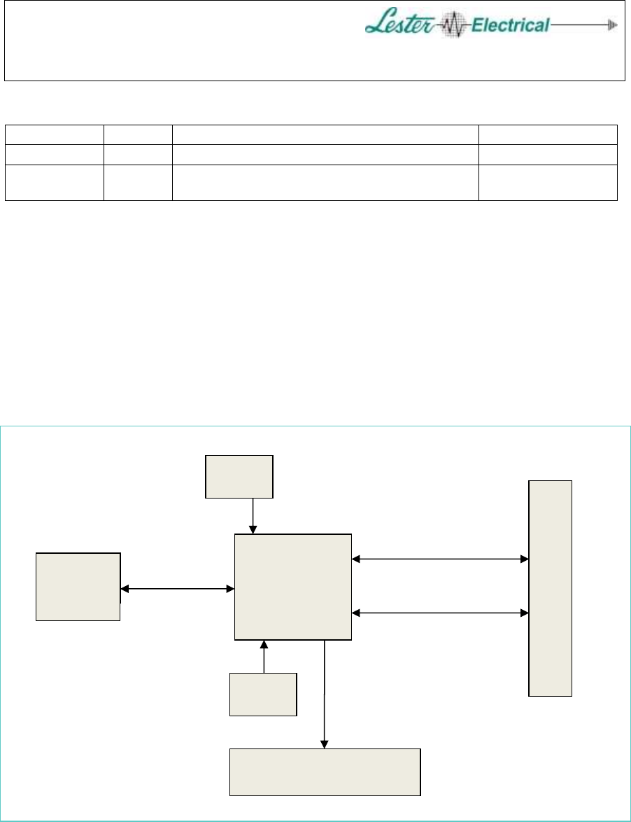
2 28170 RF Module Overview
This RF module is Bluetooth® v4.1, Low Energy (LE) compliant, and is based on the
CSR1010A05 System on a Chip (SOC) made by Cambridge Silicon Radio. This part
supports single mode, Bluetooth® Smart applications. Three LEDs are incorporated
(Green, Yellow and Red) and are driven by the CSR1010 SOC. An SPI serial interface
plus one GPIO is made available at the interface connector J1. The supply voltage also
comes from J1. The circuit is fabricated with a two layer PCB, and has a shield over all
of the RF components (except the antenna). This module includes an integrated helical
trace antenna (printed on both sides).
Figure 2-1 – Bluetooth® Module (BTM) Block Diagram
CSR1010
RF
System on
Chip
J1
I
n
t
e
r
f
a
c
e
32 Khz
XTAL
16 Mhz
XTAL
LEDs
Grn Yel Red
SPI
GPIO
Trace
Antenna
2.4 Ghz
Bluetooth®
v4.1
Document:
User's Manual
Title: Last Saved:
28170 Bluetooth® LE Module 8/19/2016 5:22:00 PM
Page 4 of 10
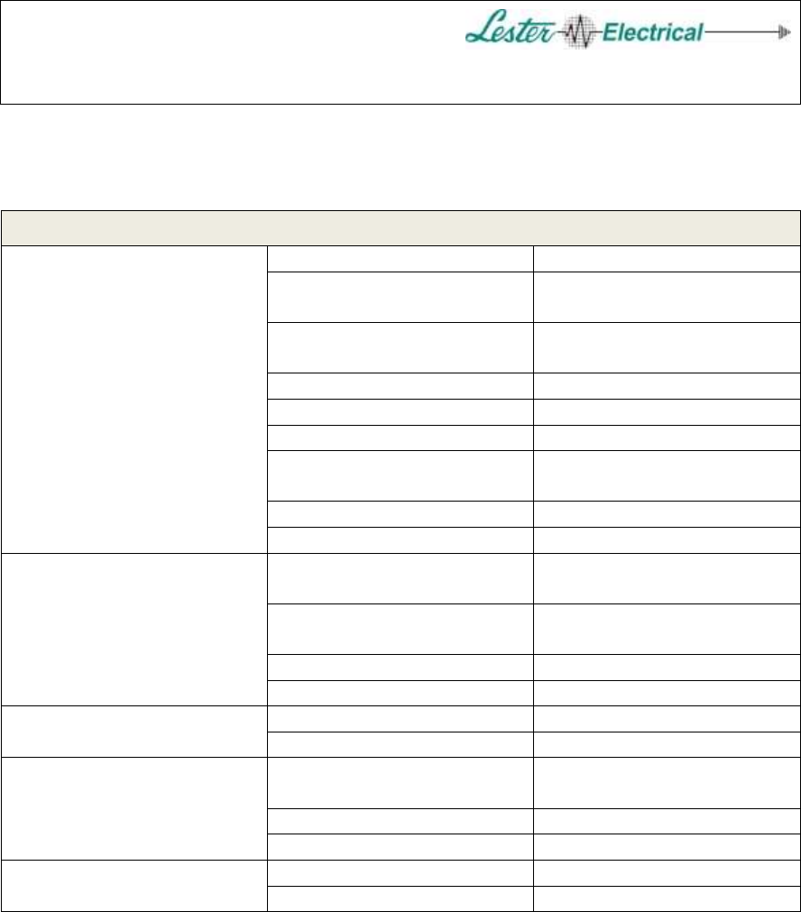
2.1 Specifications
Table 2-1 – BTM Specifications
General
Frequency
ISM 2.4 Ghz
Number of Channels
(3 used for advertising)
40
Spreading Method
Frequency hopping,
pseudo-random, adaptive
Modulation
GFSK
Bluetooth® Smart
V4.1
Antenna
Trace, Helix 2 sided
Dimensions
2.086[52.98] x 1.810[45.97]
Inches[mm] x 0.492[12.50]
Operating Temperature
-30 to 85 °C
Storage Temperature
-40 to 85 °C
Power Requirements
Supply Voltage
(Switching Regulator Input)
1.8 to 3.6 V
Transmit Current 1
(TX level = 4, 0 dBm)
18mA peak at 3.0V
Receive Current 1
20mA peak at 3.0V
Idle Current 1
1 mA at 3.0V
Available I/O
SPI Serial Port
4, including chip select
Additional GPIO
1
Performance
Transmit Output Power,
Conducted
-16 to +9 dBm
Receiver Sensitivity
-93 dBm
RF Data Rate
1 Mbps
Agency Approvals
FCC Parts 15.209, 15.247
FCC ID: OBH-28170
Industry Canada (IC)
IC: nnnnn-28170
1 Currents listed are with all LEDs off. 40mA is the maximum expected peak current, at
max transit power with all LEDs on.
Document:
User's Manual
Title: Last Saved:
28170 Bluetooth® LE Module 8/19/2016 5:22:00 PM
Page 5 of 10
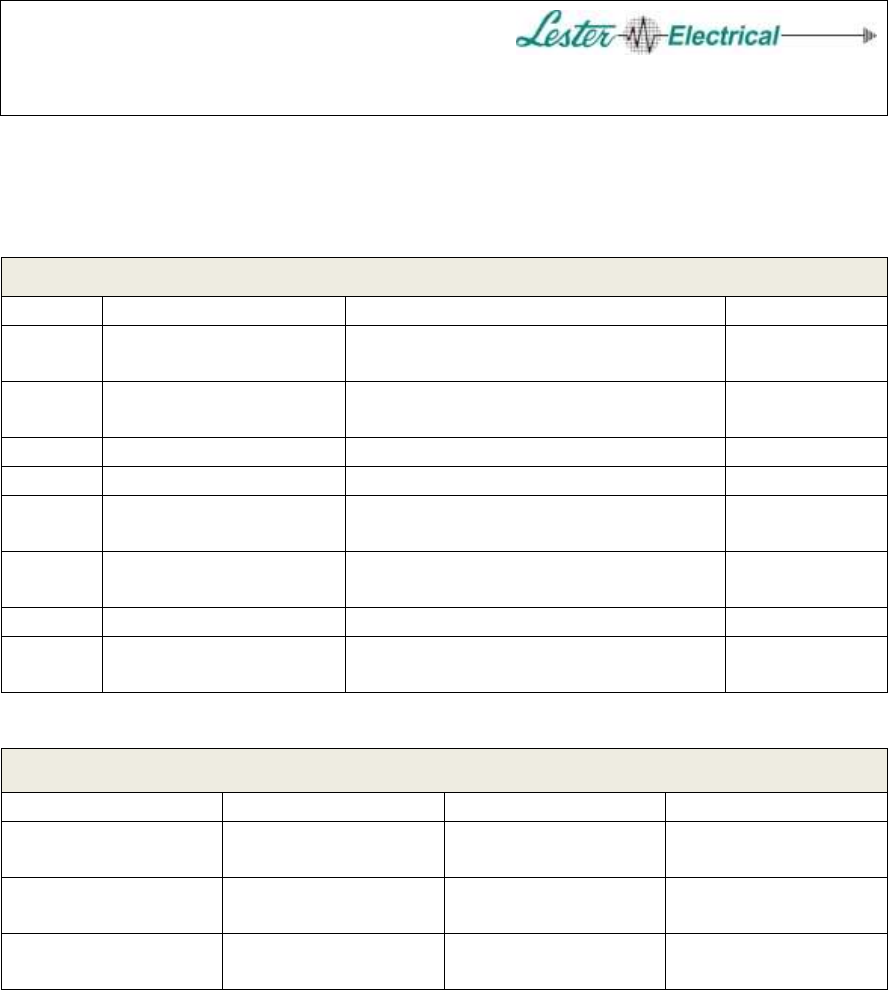
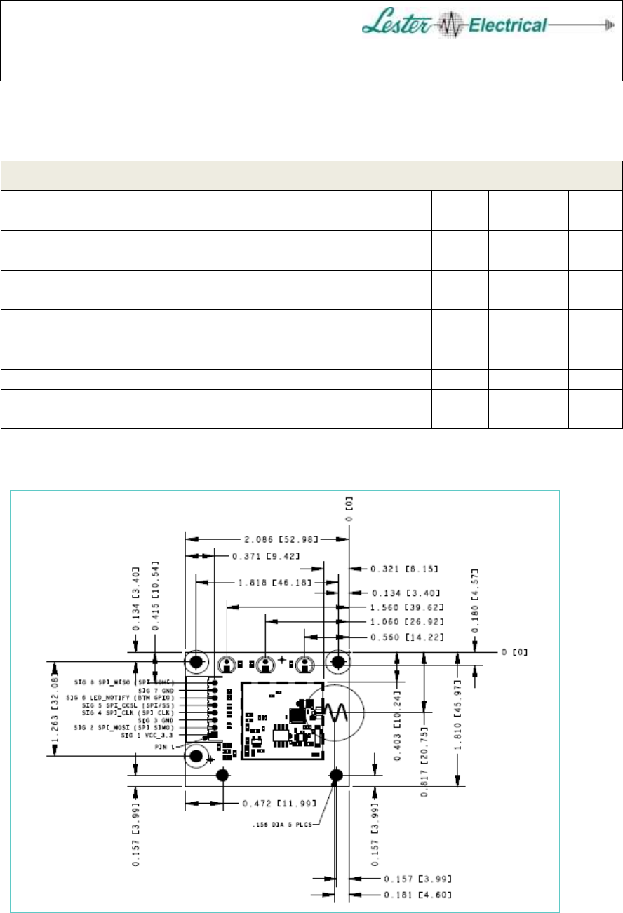
2.2 Module Pin-Out, Signal Descriptions
Table 2-2 – J1 Connector, Interface Description
J1 Pin
Signal Name
Description
Direction
1
VCC_3.3
Positive Power Supply Voltage,
Normally 3.3V
Power
2
SPI_MOSI (SPI
SIMO)
SPI Bus, Master Output / Slave Input
Input/Output
3
GND
Ground Pin
Power
4
SPI_CLK (SPI CLK)
SPI Bus, Master Clock Output
Input/Output
5
SPI_CCSL (SPI /SS)
SPI Bus, Chip Select Active Low
(/Slave Select)
Input/Output
6
LED_Notify (BTM
GPIO)
General Purpose GPIO
Input/Output
7
GND
Ground Pin
Power
8
SPI_MISO (SPI
SOMI)
SPI Bus, Master Input / Slave Output
Input/Output
Table 2-3 – BTM LED Port Pins
CSR1010 Port I/O
Signal Name
Description
Direction
PIO[0]
Grn_LED
Green LED, Active
Low - On 1
Output
PIO[1]
Yel_LED
Yellow LED, Active
Low - On 1
Output
PIO[6]
Red_LED
Red LED, Active
Low - On 2
Output
1 The Green and Yellow LEDs are shared with the CSR UART debug Pins on PIO[0] and PIO[1]. Avoid
I/O contention by not using the debug UART.
2 The Red LED is shared with the CSR Chip Select on PIO[6]. A buffer with open-drain output is
recommended (for the programming I/F) to avoid I/O contention.
Document:
User's Manual
Title: Last Saved:
28170 Bluetooth® LE Module 8/19/2016 5:22:00 PM
Page 6 of 10
2.3 Electrical Characteristics
Table 2-4 – BTM DC Characteristics
Parameter
Symbol
Condition
Min
Typ
Max
Units
Supply Voltage
VDD
1.8
3.0
3.6
V
Operating Temp
TOP
-30
85
°C
Junction Temp
TJ
125
°C
Output High
Voltage
VOH
IOH = -4mA
0.75* VDD
V
Output Low
Voltage
VOL
IOL = +4mA
0.4
V
Input High Voltage
VIH
0.7* VDD
VDD +0.4
V
Input Low Voltage
VIL
-0.4
0.3* VDD
V
Hibernate Current
IDDhib
20 °C,
VDD=3.0V
2.0
uA
2.4 Mechanical Drawings
Figure 2-2 – Bluetooth® Module (BTM) Mechanical Drawing
Document:
User's Manual
Title: Last Saved:
28170 Bluetooth® LE Module 8/19/2016 5:22:00 PM
Page 7 of 10
2.5 Module Mounting Considerations
The 28170 RF module is intended to mount on the inside of a front or end panel. This is
preferred to allow the LEDs to be visible, and keeps the antenna located behind an
opening or plastic material to allow for good RF emission. The module has a single
connector (J1) that allows for board-to-board interfacing or for using a cable to another
board. The mating connector (through hole type) is listed in the following table.
Table 2-5 – BTM Mating Connectors
Mating Connector Type
Manufacturer
Part No.
Board-to-Board Connector
JST
08JQ-ST
Inline Connector
JST
XHP-8
A plastic enclosure is recommended for best RF range. If using a metal enclosure, the
antenna should be kept clear of metal for at least 1.5 inches in all directions, if possible.
Nylon standoffs and fasteners are recommended for mounting the module to the housing.
3 Agency Certifications
3.1 United States (FCC)
The Model 28170 modules comply with Part 15 of the FCC rules and regulations.
Compliance with the labeling requirements, FCC notices and antenna usage guidelines is
required. In order to comply with FCC Certification requirements, the Original
Equipment Manufacturer (OEM) must fulfill the following requirements.
1. The system integrator must place an exterior label on the outside of the final
product housing the 28170 BTM Module. Figure 3-1 below shows the contents
that must be included in this label.
2. 28170 BTM Modules may only be used with the antenna that has been tested
and approved for use with this module.
3.1.1 OEM Labeling Requirements
NOTE: The OEM must make sure that FCC labeling requirements are met. This
includes a clearly visible exterior label on the outside of the final product housing that
displays the contents shown in Figure 3-1 below.
Document:
User's Manual
Title: Last Saved:
28170 Bluetooth® LE Module 8/19/2016 5:22:00 PM
Page 8 of 10
MANUFACTURERS NAME
BRAND NAME or TRADE NAME
Contains FCC ID: OBH-28170
This device complies with part 15 of the FCC Rules. Operation is subject to the
following two conditions: (1) This device may not cause harmful interference, and
(2) this device must accept any interference received, including interference that may
cause undesired operation.
Figure 3-1 – FCC Label
NOTE: If the device is smaller than the palm of your hand and this will not fit on a label,
the last line is allowed to go into the user’s manual instead.
3.1.2 FCC Notices
WARNING: The 28170 modules have been tested by the FCC for use with other
products without further certification (as per FCC Section 2.1091). Changes or
modifications not expressly approved by the party responsible for compliance could void
the user's authority to operate the equipment.
NOTE: OEM's must verify final end product to comply with unintentional radiators
(FCC Section 15.107 and 15.109) before declaring compliance of their final product to
Part 15 of the FCC rules.
NOTE: The 28170 modules have been certified for remote and base radio applications.
If the module will be used for portable applications, the device must undergo the
applicable SAR testing.
NOTE: This equipment has been tested and found to comply with the limits for a Class B
digital device, pursuant to part 15 of the FCC Rules. These limits are designed to provide
reasonable protection against harmful interference in a residential installation. This
equipment generates, uses and can radiate radio frequency energy and, if not installed and
used in accordance with the instructions, may cause harmful interference to radio
communications. However, there is no guarantee that interference will not occur in a
particular installation. If this equipment does cause harmful interference to radio or
television reception, which can be determined by turning the equipment off and on, the

Document:
User's Manual
Title: Last Saved:
28170 Bluetooth® LE Module 8/19/2016 5:22:00 PM
Page 9 of 10
user is encouraged to try to correct the interference by one or more of the following
measures:
Reorient or relocate the receiving antenna.
Increase the separation between the equipment and receiver.
Connect the equipment into an outlet on a circuit different from that to which the
receiver is connected.
Consult the dealer or an experienced radio/TV technician for help.
NOTE: The preceding statement must be included as a CAUTION statement in OEM
product manuals, in order to alert users of FCC RF Exposure compliance.
NOTE: This transmitter must not be co-located with any other transmitters
except in accordance with FCC multi-transmitter product procedures
NOTE: This filing meets the SAR threshold exclusion set forth in KDB 447498
and therefore can be used in mobile/portable configurations.
3.1.3 FCC Approved Antennas
The 28170 RF modules are FCC-approved for fixed base station and mobile applications.
The FCC requirement for mobile applications states that the antenna must be mounted at
least 20 cm (8 in) from nearby persons. Only the provided, permanently attached, PCB
trace type antenna is approved for use. The 28170 module does not include any other
antenna option.
3.2 Canada (IC)
This device complies with Industry Canada license-exempt RSS standard(s). Operation
is subject to the following two conditions: (1) this device may not cause interference, and
(2) this device must accept any interference, including interference that may cause
undesired operation of the device.
Le présent appareil est conforme aux CNR d'Industrie Canada applicables aux
appareils radio exempts de licence. L'exploitation est autorisée aux deux conditions
suivantes: (1) l'appareil ne doit pas produire de brouillage, et (2) l'utilisateur de
l'appareil doit accepter tout brouillage radioélectrique subi, même si le brouillage est
susceptible d'en compromettre le fonctionnement.
Under Industry Canada regulations, this radio transmitter may only operate using an
antenna of a type and maximum (or lesser) gain approved for the transmitter by Industry
Canada. For this device, the only antenna option is a permanently attached, PCB trace
type, and does not include any other antenna option.
Document:
User's Manual
Title: Last Saved:
28170 Bluetooth® LE Module 8/19/2016 5:22:00 PM
Page 10 of 10
Conformément à la réglementation d'Industrie Canada, le présent émetteur radio peut
fonctionner avec une antenne d'un type et d'un gain maximal (ou inférieur) approuvé
pour l'émetteur par Industrie Canada. Pour cet appareil, la seule option de l'antenne
est un type de trace PCB fixé de façon permanente, et ne comprennent pas toute autre
option d'antenne.
3.2.1 OEM Labeling Requirements
Labeling requirements for Industry Canada are similar to those of the FCC. A clearly
visible label on the outside of the final product housing must display the contents shown
in Figure 3-2 below.
MANUFACTURERS NAME
BRAND NAME or TRADE NAME
MODEL:
Contains IC: nnnnn-28170
Figure 3-2 – IC Label
NOTE: The OEM can choose to implement a single label combined for both FCC and IC
labeling requirements. If a combined single label is chosen, there must be a clearly
visible label on the outside of the final product housing displaying the contents shown in
Figure 3-3 below.
MANUFACTURERS NAME
BRAND NAME or TRADE NAME
Contains FCC ID: OBH-28170
Contains IC: nnnnn-28170
This device complies with part 15 of the FCC Rules. Operation is subject to the
following two conditions: (1) This device may not cause harmful interference, and
(2) this device must accept any interference received, including interference that may
cause undesired operation.
Figure 3-3 – Combined FCC and IC Label