Lexmark 0528RFU UHF RFID Option User Manual PowerPoint Presentation
Lexmark International Inc UHF RFID Option PowerPoint Presentation
Lexmark >
Contents
- 1. Antenna List with Gain
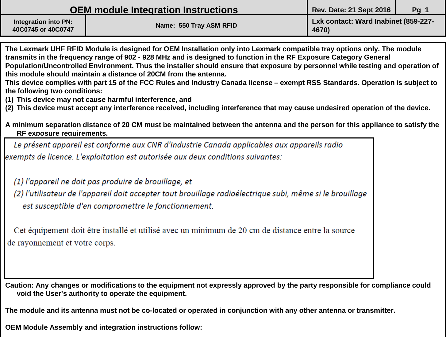
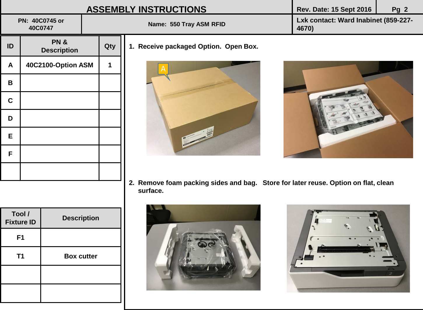
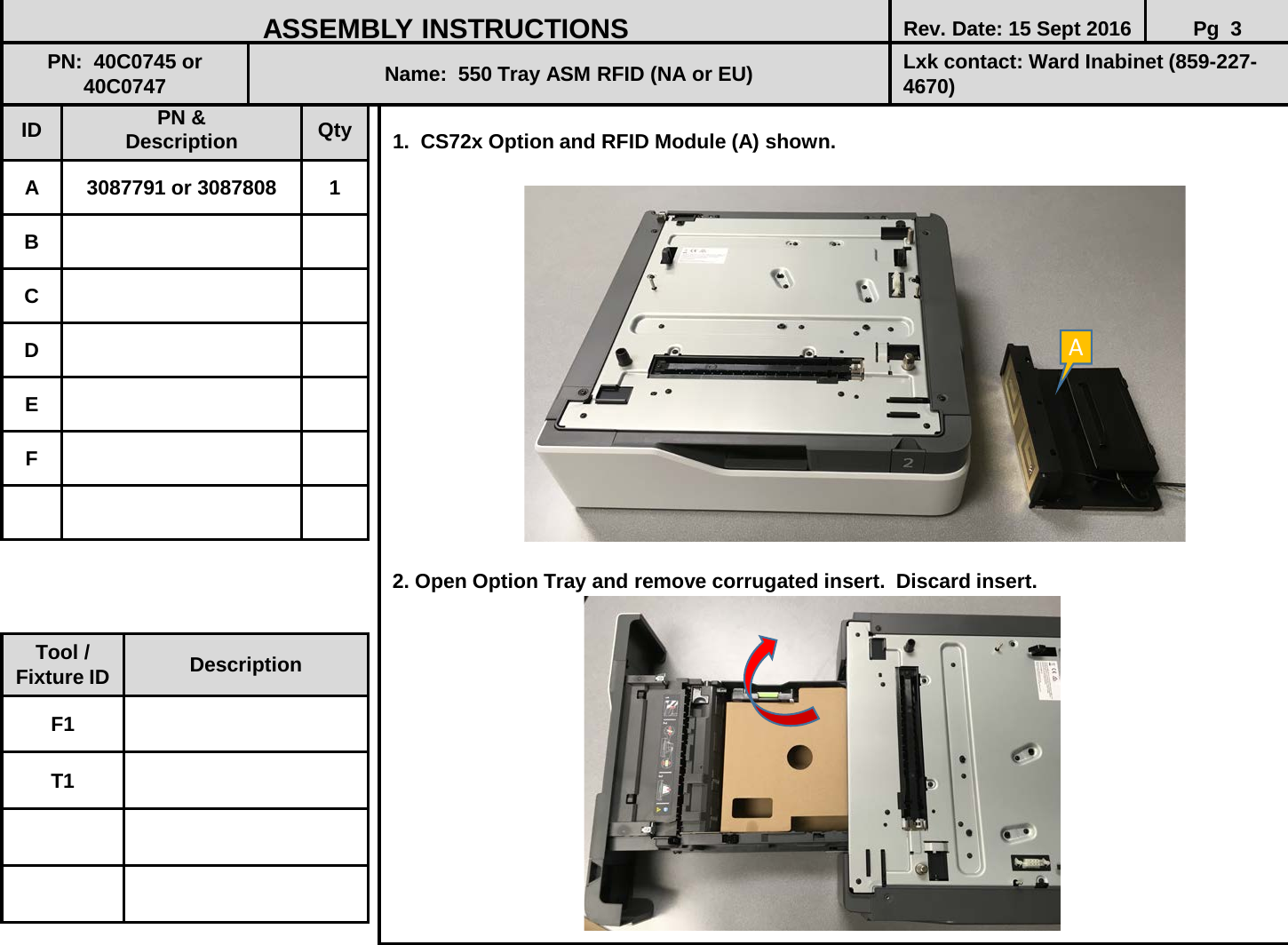
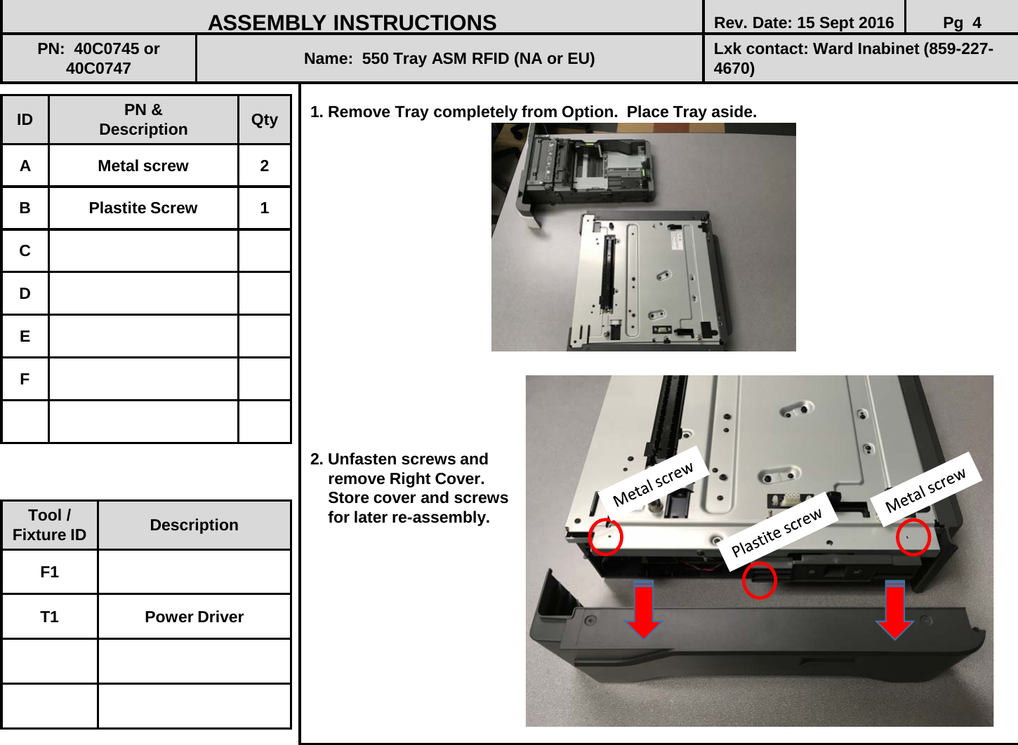
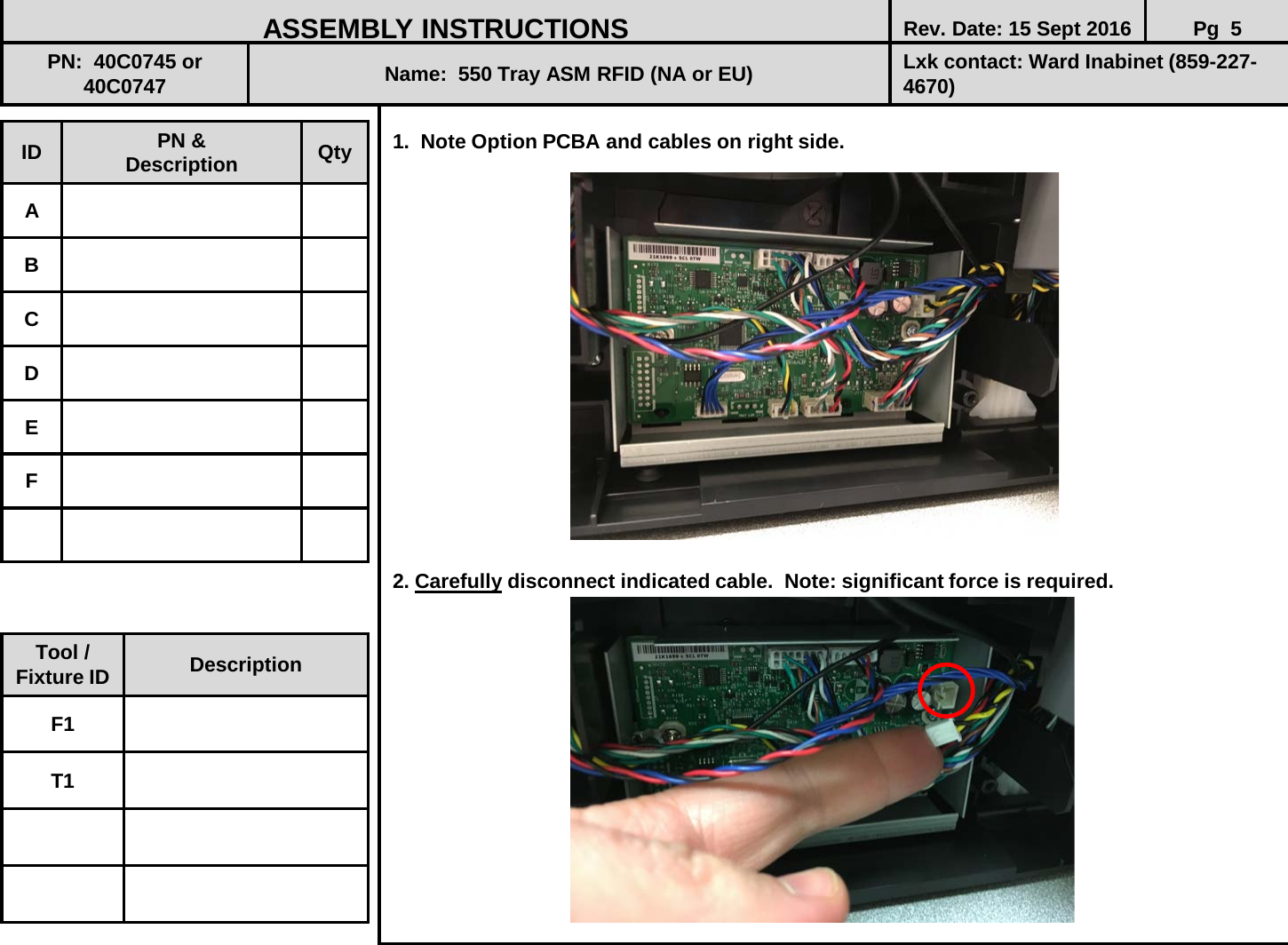
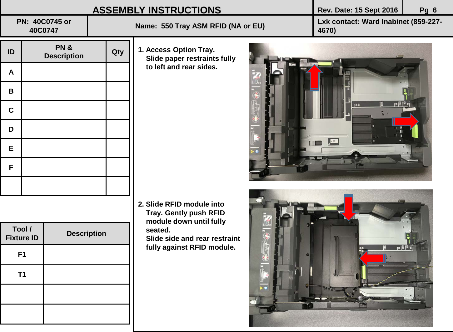
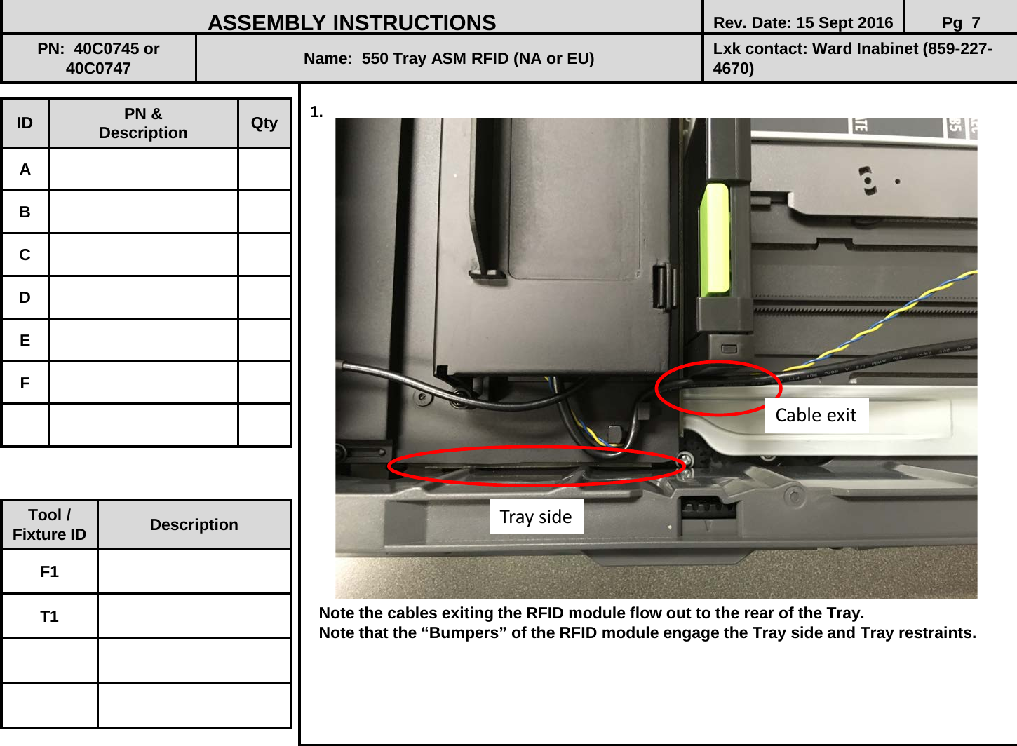
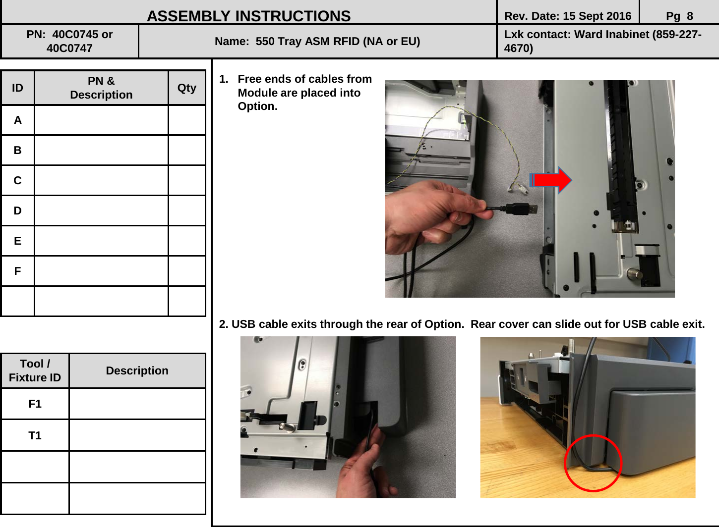
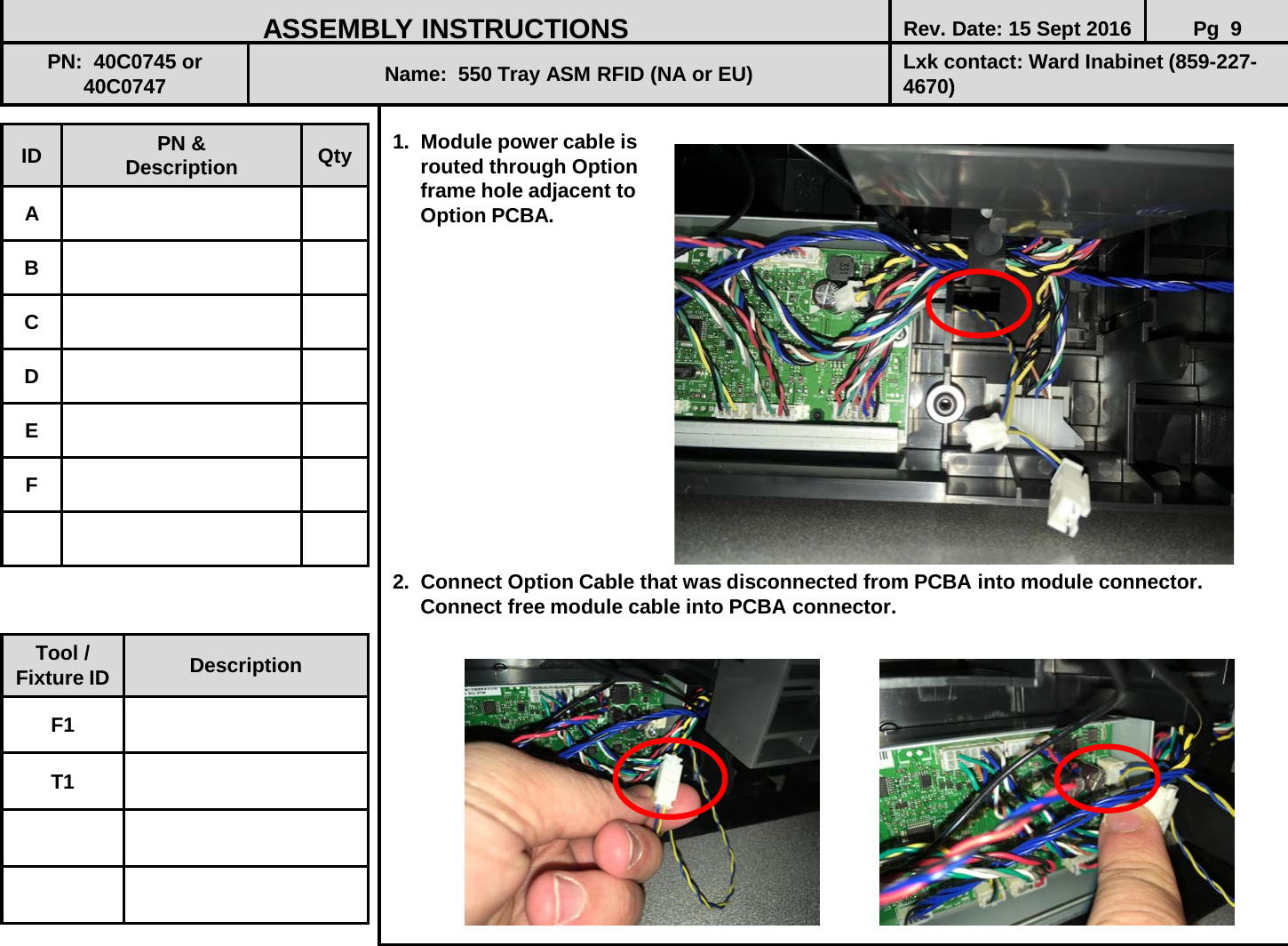
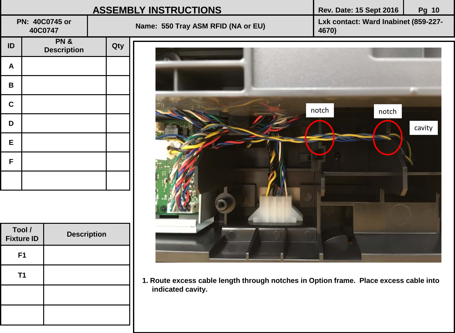
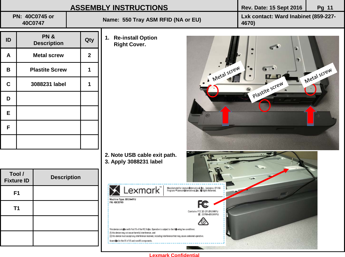
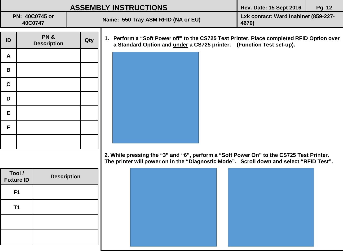
- 2. OEM Integration Instructions
- 3. User Manual
OEM Integration Instructions