Lexmark 0528RFU UHF RFID Option User Manual PowerPoint Presentation
Lexmark International Inc UHF RFID Option PowerPoint Presentation
Lexmark >
Contents
- 1. Antenna List with Gain
- 2. OEM Integration Instructions
- 3. User Manual
OEM Integration Instructions
The Lexmark UHF RFID Module is designed for OEM Installation only into Lexmark compatible tray options only. The module
transmits in the frequency range of 902 - 928 MHz and is designed to function in the RF Exposure Category General
Population/Uncontrolled Environment. Thus the installer should ensure that exposure by personnel while testing and operation of
this module should maintain a distance of 20CM from the antenna.
This device complies with part 15 of the FCC Rules and Industry Canada license – exempt RSS Standards. Operation is subject to
the following two conditions:
(1) This device may not cause harmful interference, and
(2) This device must accept any interference received, including interference that may cause undesired operation of the device.
A minimum separation distance of 20 CM must be maintained between the antenna and the person for this appliance to satisfy the
RF exposure requirements.
Caution: Any changes or modifications to the equipment not expressly approved by the party responsible for compliance could
void the User’s authority to operate the equipment.
The module and its antenna must not be co-located or operated in conjunction with any other antenna or transmitter.
OEM Module Assembly and integration instructions follow:
OEM module Integration Instructions Rev. Date: 21 Sept 2016 Pg 1
Integration into PN:
40C0745 or 40C0747 Name: 550 Tray ASM RFID Lxk contact: Ward Inabinet (859-227-
4670)
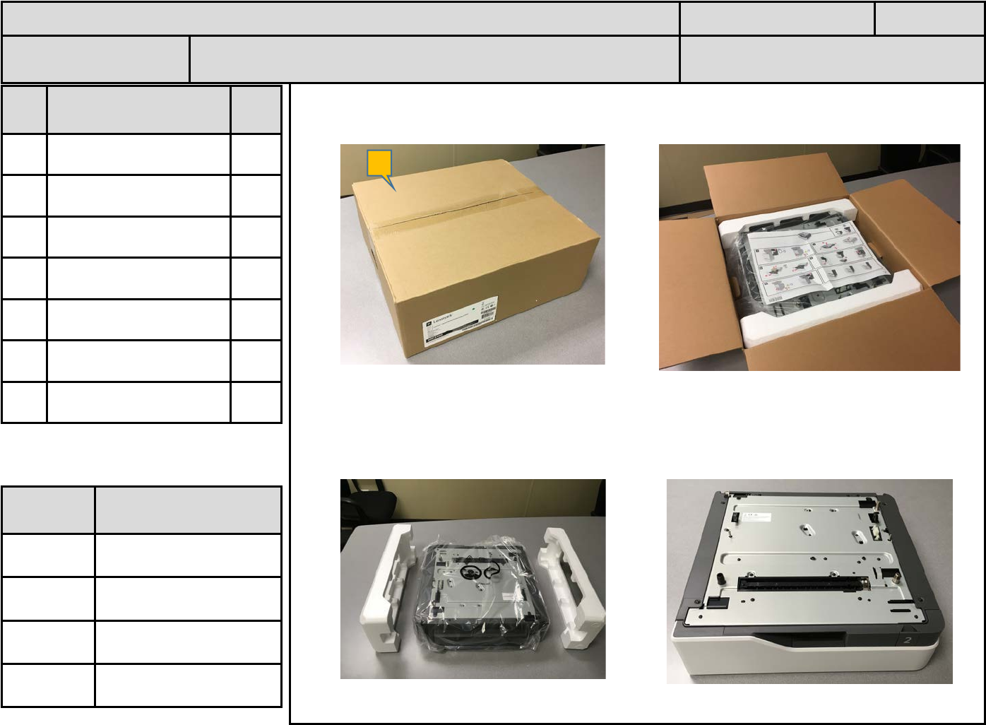
1. Receive packaged Option. Open Box.
2. Remove foam packing sides and bag. Store for later reuse. Option on flat, clean
surface.
ID PN &
Description Qty
A 40C2100-Option ASM 1
B
C
D
E
F
ASSEMBLY INSTRUCTIONS Rev. Date: 15 Sept 2016 Pg 2
PN: 40C0745 or
40C0747 Name: 550 Tray ASM RFID Lxk contact: Ward Inabinet (859-227-
4670)
Tool /
Fixture ID Description
F1
T1 Box cutter
A
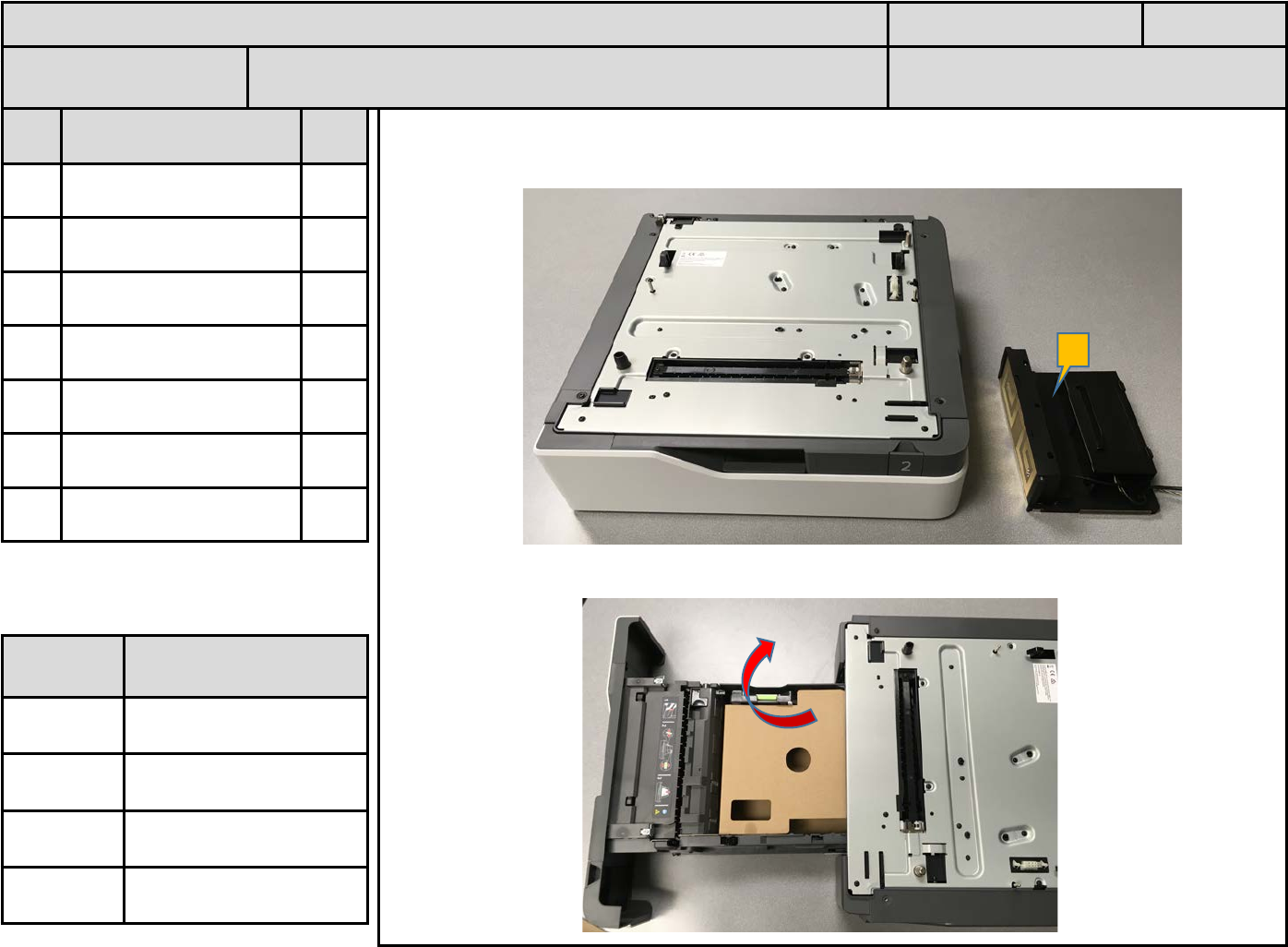
1. CS72x Option and RFID Module (A) shown.
2. Open Option Tray and remove corrugated insert. Discard insert.
ID PN &
Description Qty
A 3087791 or 3087808 1
B
C
D
E
F
ASSEMBLY INSTRUCTIONS Rev. Date: 15 Sept 2016 Pg 3
PN: 40C0745 or
40C0747 Name: 550 Tray ASM RFID (NA or EU) Lxk contact: Ward Inabinet (859-227-
4670)
Tool /
Fixture ID Description
F1
T1
A
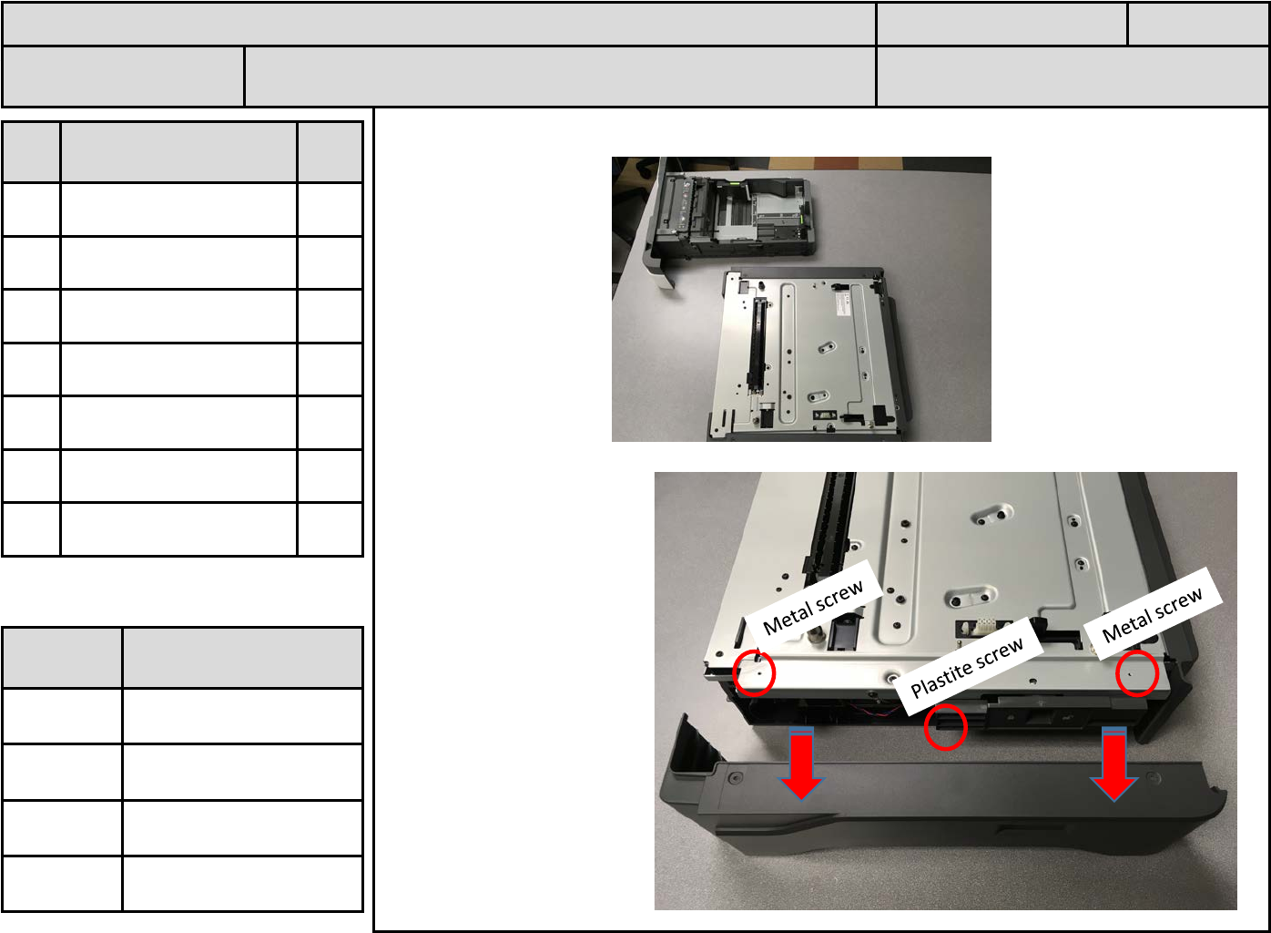
1. Remove Tray completely from Option. Place Tray aside.
2. Unfasten screws and
remove Right Cover.
Store cover and screws
for later re-assembly.
ID PN &
Description Qty
A Metal screw 2
B Plastite Screw 1
C
D
E
F
ASSEMBLY INSTRUCTIONS Rev. Date: 15 Sept 2016 Pg 4
PN: 40C0745 or
40C0747 Name: 550 Tray ASM RFID (NA or EU) Lxk contact: Ward Inabinet (859-227-
4670)
Tool /
Fixture ID Description
F1
T1 Power Driver
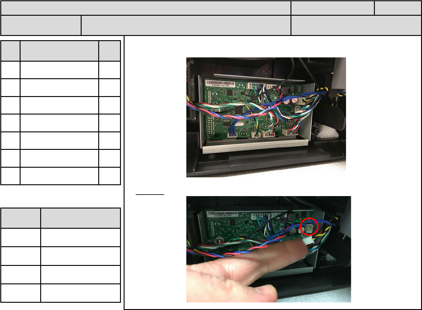
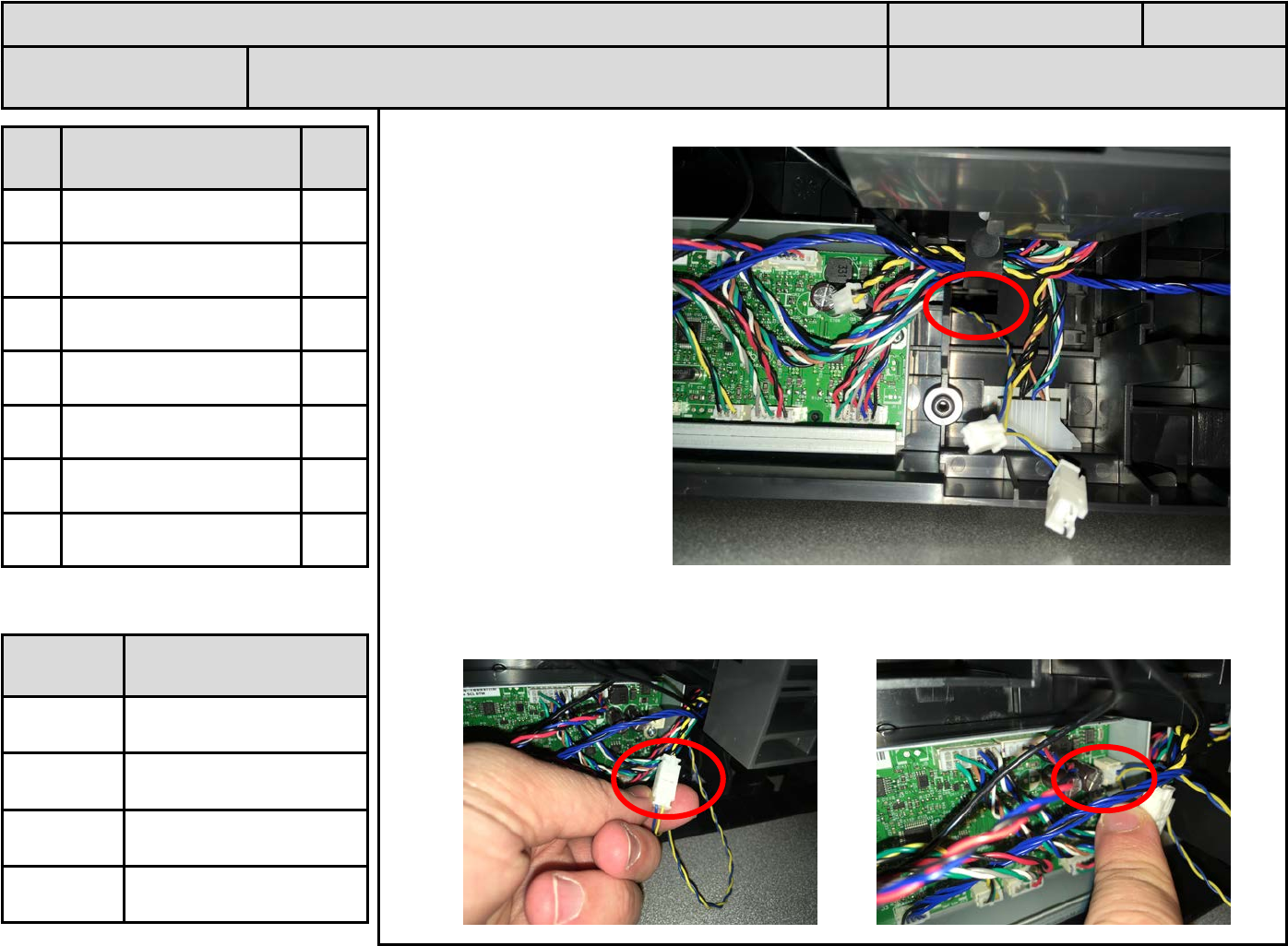
1. Note Option PCBA and cables on right side.
2. Carefully disconnect indicated cable. Note: significant force is required.
ID PN &
Description Qty
A
B
C
D
E
F
ASSEMBLY INSTRUCTIONS Rev. Date: 15 Sept 2016 Pg 5
PN: 40C0745 or
40C0747 Name: 550 Tray ASM RFID (NA or EU) Lxk contact: Ward Inabinet (859-227-
4670)
Tool /
Fixture ID Description
F1
T1
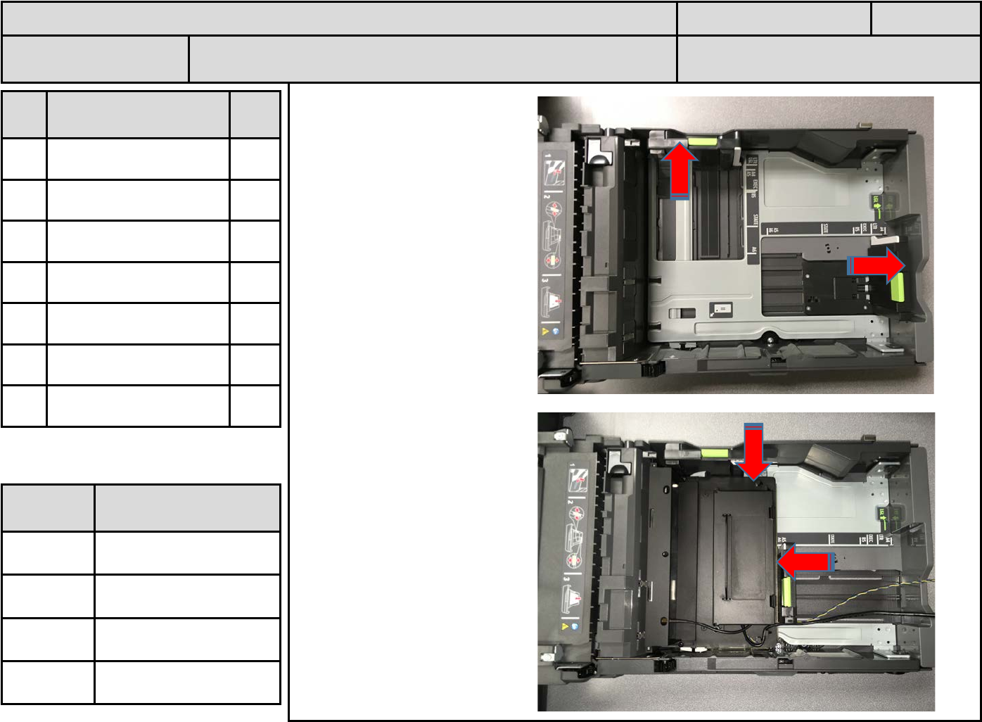
1. Access Option Tray.
Slide paper restraints fully
to left and rear sides.
2. Slide RFID module into
Tray. Gently push RFID
module down until fully
seated.
Slide side and rear restraint
fully against RFID module.
ID PN &
Description Qty
A
B
C
D
E
F
ASSEMBLY INSTRUCTIONS Rev. Date: 15 Sept 2016 Pg 6
PN: 40C0745 or
40C0747 Name: 550 Tray ASM RFID (NA or EU) Lxk contact: Ward Inabinet (859-227-
4670)
Tool /
Fixture ID Description
F1
T1
1.
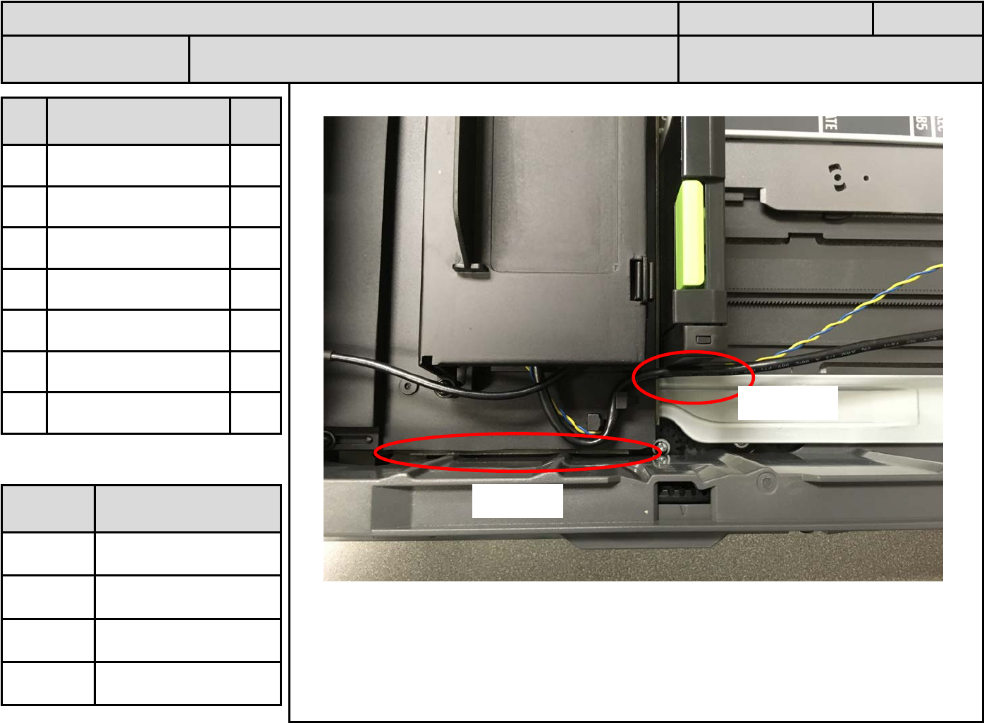
Note the cables exiting the RFID module flow out to the rear of the Tray.
Note that the “Bumpers” of the RFID module engage the Tray side and Tray restraints.
ID PN &
Description Qty
A
B
C
D
E
F
ASSEMBLY INSTRUCTIONS Rev. Date: 15 Sept 2016 Pg 7
PN: 40C0745 or
40C0747 Name: 550 Tray ASM RFID (NA or EU) Lxk contact: Ward Inabinet (859-227-
4670)
Tool /
Fixture ID Description
F1
T1
Tray side
Cable exit
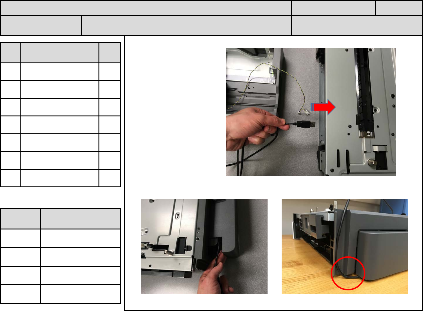
1. Free ends of cables from
Module are placed into
Option.
2. USB cable exits through the rear of Option. Rear cover can slide out for USB cable exit.
ID PN &
Description Qty
A
B
C
D
E
F
ASSEMBLY INSTRUCTIONS Rev. Date: 15 Sept 2016 Pg 8
PN: 40C0745 or
40C0747 Name: 550 Tray ASM RFID (NA or EU) Lxk contact: Ward Inabinet (859-227-
4670)
Tool /
Fixture ID Description
F1
T1
1. Module power cable is
routed through Option
frame hole adjacent to
Option PCBA.
2. Connect Option Cable that was disconnected from PCBA into module connector.
Connect free module cable into PCBA connector.
ID PN &
Description Qty
A
B
C
D
E
F
ASSEMBLY INSTRUCTIONS Rev. Date: 15 Sept 2016 Pg 9
PN: 40C0745 or
40C0747 Name: 550 Tray ASM RFID (NA or EU) Lxk contact: Ward Inabinet (859-227-
4670)
Tool /
Fixture ID Description
F1
T1
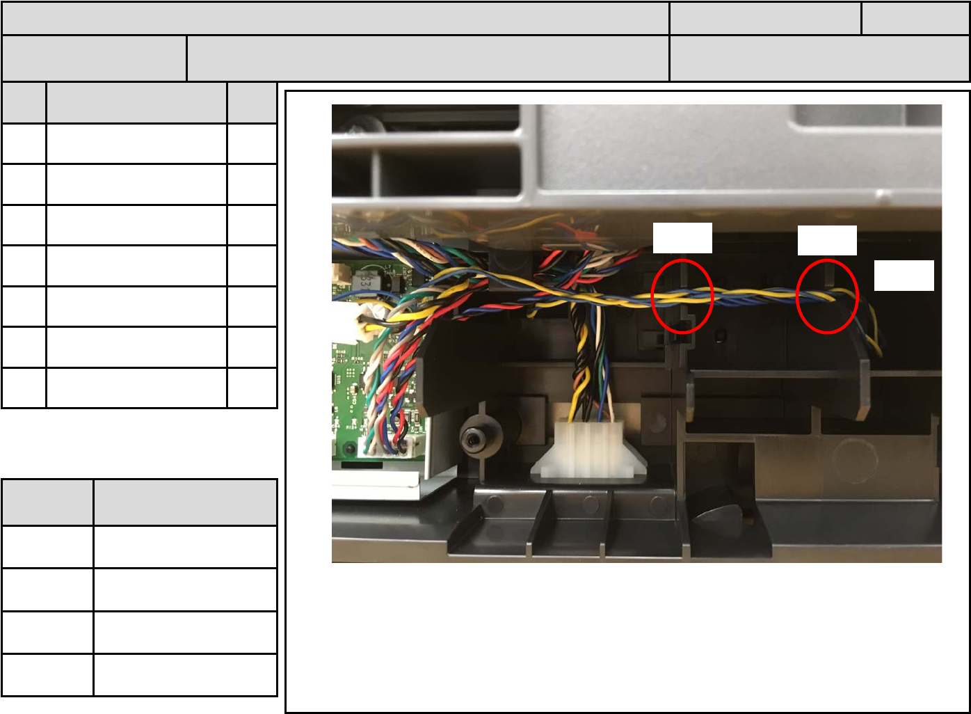
1. Route excess cable length through notches in Option frame. Place excess cable into
indicated cavity.
ID PN &
Description Qty
A
B
C
D
E
F
ASSEMBLY INSTRUCTIONS Rev. Date: 15 Sept 2016 Pg 10
PN: 40C0745 or
40C0747 Name: 550 Tray ASM RFID (NA or EU) Lxk contact: Ward Inabinet (859-227-
4670)
Tool /
Fixture ID Description
F1
T1
cavity
notch
notch
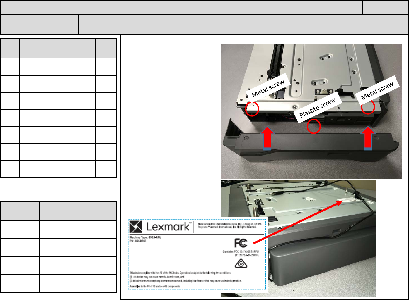
1. Re-install Option
Right Cover.
2. Note USB cable exit path.
3. Apply 3088231 label
ID PN &
Description Qty
A Metal screw 2
B Plastite Screw 1
C 3088231 label 1
D
E
F
ASSEMBLY INSTRUCTIONS Rev. Date: 15 Sept 2016 Pg 11
PN: 40C0745 or
40C0747 Name: 550 Tray ASM RFID (NA or EU) Lxk contact: Ward Inabinet (859-227-
4670)
Tool /
Fixture ID Description
F1
T1
Lexmark Confidential
1. Perform a “Soft Power off” to the CS725 Test Printer. Place completed RFID Option over
a Standard Option and under a CS725 printer. (Function Test set-up).
2. While pressing the “3” and “6”, perform a “Soft Power On” to the CS725 Test Printer.
The printer will power on in the “Diagnostic Mode”. Scroll down and select “RFID Test”.
ID PN &
Description Qty
A
B
C
D
E
F
ASSEMBLY INSTRUCTIONS Rev. Date: 15 Sept 2016 Pg 12
PN: 40C0745 or
40C0747 Name: 550 Tray ASM RFID (NA or EU) Lxk contact: Ward Inabinet (859-227-
4670)
Tool /
Fixture ID Description
F1
T1
1. Load about 20 pages of RFID media into the Standard Option.
2. While pressing the “3” and “6”, perform a “Soft Power On” to the CS725 Test Printer.
The printer will power on in the “Diagnostic Mode”. Scroll down and select “RFID Test”.
3. Select “Test Page 1”. Test page one will print out. Following the instructions on this
sheet, place this ”Test Page 1” back into the Standard Option printed side up with the
arrow pointing toward the front of the printer. If this test page prints out, then this part of
the Function Test is successful.
4. Select “Test Page 2”. Test page two will print out (this sheet is the same actual sheet as
Test page one. Follow the instructions on this sheet, load one page of normal, non-RFID
media into the Standard Option. If this test page prints out, then this part of the Function
Test is successful.
5. Select “Test page 3”. Test page three will print out. This page should duplex and print a
“Invalid Tag” on the back side. Note the Instructions on the front side of the Test page
three. If “Invalid Tag” is on the back side, then the full Function Test is successful.
6. Perform a “Soft Power off” to the printer. Remove the RFID Option from the test set-up.
ID PN &
Description Qty
A
B
C
D
E
F
ASSEMBLY INSTRUCTIONS Rev. Date: 15 Sept 2016 Pg 13
PN: 40C0745 or
40C0747 Name: 550 Tray ASM RFID (NA or EU) Lxk contact: Ward Inabinet (859-227-
4670)
Tool /
Fixture ID Description
F1
T1
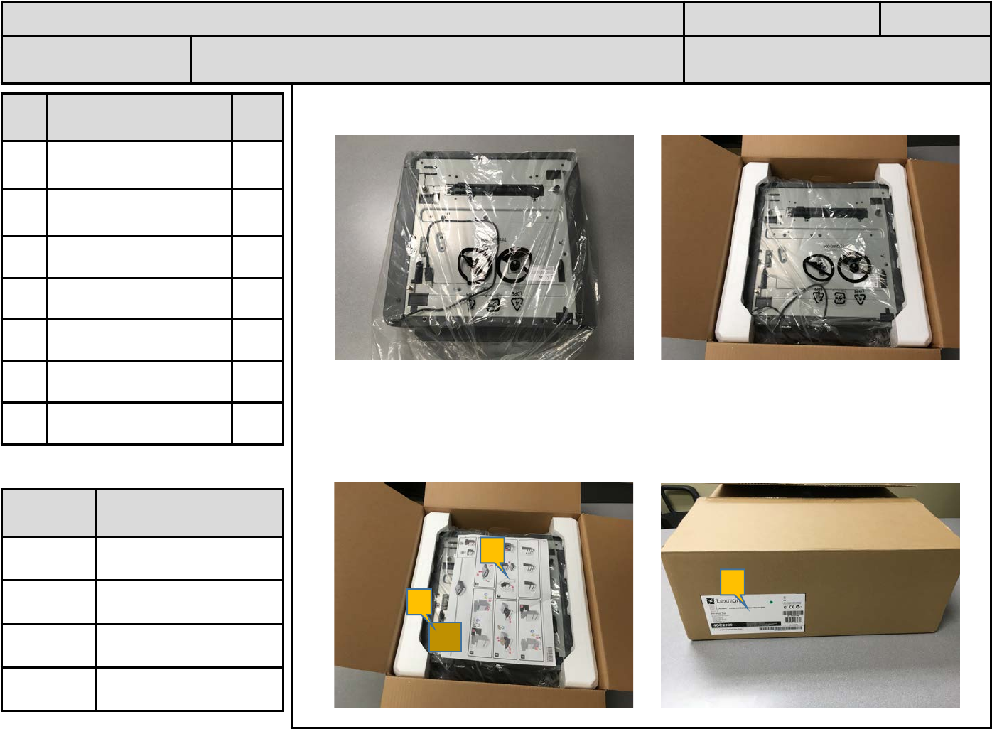
1. Repackage Option.
2. Place Set-Up sheet (A) and Forms Card (C) into Option Packaging. Tape Carton. Print
out the RFID Option Carton label (B) and affix over the original Carton label.
ID PN &
Description Qty
A 3088223-RFID Option
Sheet 1
B 3088232-RFID Carton
Label 2
C 40C9200-Forms Card 1
D
E
F
ASSEMBLY INSTRUCTIONS Rev. Date: 15 Sept 2016 Pg 14
PN: 40C0745 or
40C0747 Name: 550 Tray ASM RFID (NA or EU) Lxk contact: Ward Inabinet (859-227-
4670)
Tool /
Fixture ID Description
F1
T1
A
B
C