Li Seng Technology SH-IOTML30BP IotT Module User Manual
Li Seng Technology Limited IotT Module
User Manual
!
!
Living!Smart!
Page!|!1!
!
IoT$Module$$
!
!
!
!
!
!
!
!
!
!
!
!
Model!No:!SH-IOTML3XBP-XX!
Rev!2.0
November!4,!2016! !
!

!
!
Living!Smart!
Page!|!2!
1. Description$
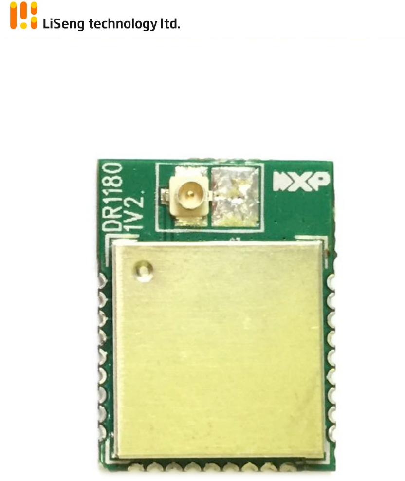
SH-IOTML3XBP!module!is!a!low! cost,! compact!size,! low! power,! high! performance! surface! mount!
transceiver!with! 2.4GHz! IEEE! 802.15.4,! Zigbee!compliance,! by! using! the! high! performance! NXP!
JN5169!microcontroller.!
It!is!targeted!for!Smart!Home!Control!customers.!!With!this!module,!customers!may!develop!their!
own!Smart!Home!Device!(like:!lighting,!door!lock!and!home!appliances)!easily!with!provided!SDK.!!It!
may!work!with!Li!Seng!Gateway!to!achieve!Smart!Home!Control!features.!
2. Features$
Modules$General$$
v 2.4GHz!IEEE!802.15.4,!Zigbee!Light!Link!&!Home!Automation!1.2!Compatible!
v Lead-free!and!RoHS!compliant!
!
• TX!power!+8.5dBm!
• Receive!sensitivity!-96dBm!
• TX!current!21mA!
• RX!current!13mA!!!
• 2.0V!to!3.6V!operation!!
• 128-bit!AES!security!processor!
• MAC!accelerator!with!packet!formatting,!CRCs,!address!check,!auto-acks,!timers!
!
Microcontroller$$
• 32-bit!RISC!CPU,!up!to!32MIPs!with!low!power!
• Data!EEPROM!with!guaranteed!100k!write!operations!
• ZigBee!stacks!
• JTAG!debug!interface!
• 4-input!10-bit!ADC,!1!comparator!
• 5!x!PWM!(4!x!timer,!1!x!timer/counter)!
• 2!UARTs!
• SPI!Master!&!Slave!port!with!3!selects!
• 2-wire!serial!interface!
• Battery!and!Temperature!Sensor!
• Watchdog!timer!and!BOR!
• Up!to!20!DIO!
!
!
Living!Smart!
Page!|!3!
!
3. Dimension$and$Pin$Assignment$
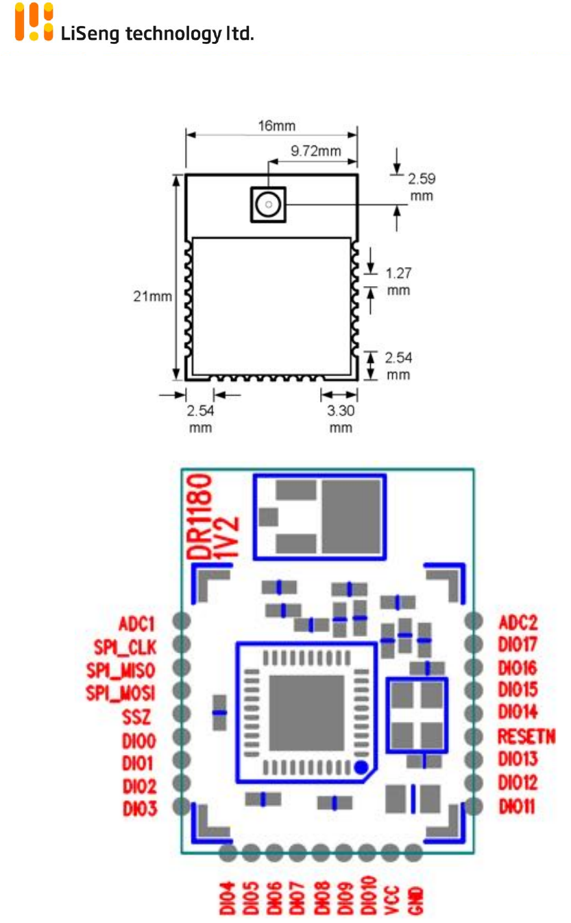
a. Dimension:!
!
!!!Fig!1.!Dimension!of!the!module!
!
!!!Fig!2.!Location!of!the!pins!
!
!
!
!
!
!
!
Living!Smart!
Page!|!4!
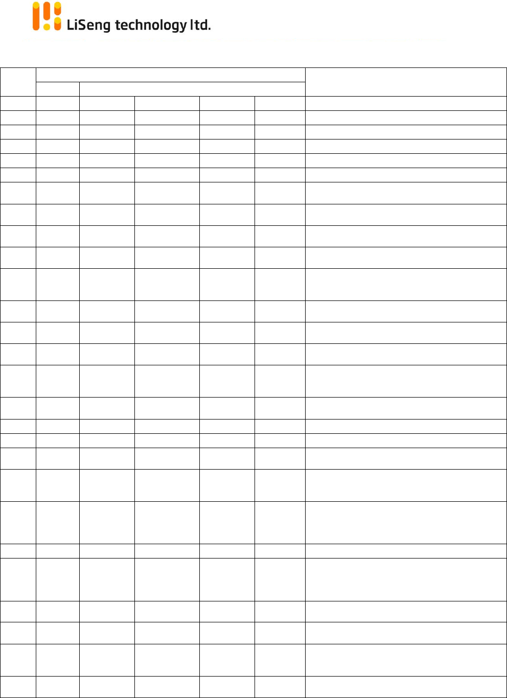
b. Pin!Assignment:!
Pin$No$
Pin$Fucntions$
Description$
Primary$
Alternate$Functions$
1!
ADC1!
!!
!!
!!
!!
Analogue!to!Digital!Input!
2!
DO0!
SPICLK!
!!
!!
PWM2!
SPI!Master!Clock!Output!or!PWM2!Output!
3!
DO1!
SPIMISO!
!!
!!
PWM3!
SPI!Master!In!Slave!Out!Input!or!PWM3!Output!
4!
DIO18!
SPIMOSI!
!!
!!
!!
SPI!Master!Out!Slave!In!Output!
5!
DIO19!
SPISEL0!
!!
!!
!!
SPI!Master!Select!Output!0!
6!
DIO0!
SPISEL1!
ADC3!
!!
!!
DIO0,!SPI!Master!Select!Output!1!or!ADC!input!3!
7!
IO1!
SPISEL2!
ADC4!
PC0!
!!
DIO1,!SPI!Master!Select!Output!2,!ADC!input!4!or!Pulse!
Counter!0!Input!
8!
DIO2*!
!!
RFRX!
TIM0CK_GT!
!!
DIO2,!Radio!Receive!Control!Output!or!Timer0!
Clock/Gate!Input!
9!
DIO3*!
!!
RFTX!
TIM0CAP!
!!
DIO3,!Radio!Transmit!Control!Output!or!Timer0!Capture!
Input!
10!
DIO4!
CTS0!
JTAG_TCK!
TIM0OUT!
PC0!
DIO4,!UART!0!Clear!To!Send!Input,!JTAG!CLK!Input,!
Timer0!PWM!Output,!or!Pulse!Counter!0!input!
11!
DIO5!
RTS0!
JTAG_TMS!
PWM1!
PC1!
DIO5,!UART!0!Request!To!Send!Output,!JTAG!Mode!
Select!Input,!PWM1!Output!or!Pulse!Counter!1!Input!
12!
DIO6!
TXD0!
JTAG_TDO!
PWM2!
!!
DIO6,!UART!0!Transmit!Data!Output,!JTAG!Data!Output!
or!PWM2!Output!
13!
DIO7!
RXD0!
JTAG_TDI!
PWM3!
!!
DIO7,!UART!0!Receive!Data!Input,!JTAG!Data!Input!or!
PWM!3!Output!
14!
DIO8!
TIM0CK_GT!
PC1!
PWM4!
!!
DIO8,!Timer0!Clock/Gate!Input,!Pulse!Counter1!Input!or!
PWM!4!Output!
15!
DIO9!
TIM0CAP!
32KXTALIN!
RXD1!
32KIN!
DIO9,!Timer0!Capture!Input,!32K!External!Crystal!Input,!
UART!1!Receive!Data!Input!or!32K!external!clock!Input!
16!
DIO10!
TIM0OUT!
32KXTALOUT!
!!
!!
DIO10,!Timer0!PWM!Output!or!32K!External!Crystal!
Output!
17!
VDD!
!!
!!
!!
!!
Supply!Voltage!
18!
GND!
!!
!!
!!
!!
Digital!Ground!
19!
DIO11!
PWM1!
!!
TXD1!
!!
DIO11,!PWM1!Output!or!UART!1!Transmit!Data!Output!
20!
DIO12!
PWM2!
CTS0!
JTAG_TCK!
ADO!or!
SPISMOSI!
DIO12,!PWM2!Output,!UART!0!Clear!To!Send!Input,!JTAG!
CLK!Input,!Antenna!Diversity!Odd!Output!or!SPI!Slave!
Master!Out!Slave!In!Input!
21!
DIO13!
PWM3!
RTS0!
JTAG_TMS!
ADE!or!
SPISMISO!
DIO13,!PWM3!Output,!UART!0!Request!To!Send!Output,!
JTAG!Mode!Select!Input,!Antenna!Diversity!Even!output!
or!SPI!Slave!Master!In!Slave!Out!Output!
22!
RESETN!
!!
!!
!!
!!
Reset!input!
23!
DIO14!
SIF_CLK!
TXD0!TXD1!
JTAG_TDO!
SPISEL1!or!
SPISSEL!
DIO14,!Serial!Interface!Clock!UART!0!Transmit!Data!
Output,!UART!1!Transmit!Data!Output,!JTAG!Data!
Output,!SPI!Master!Select!Output!1!or!SPI!Slave!Select!
Input!!!!!
24!
DIO15!
SIF_D!
RXD0!RXD1!
JTAG_TDI!
SPISEL2!
DIO15,!Serial!Interface!Data!or!Intelligent!Peripheral!
Data!Out!
25!
DIO16!
COMP1P!
SIF_CLK!
SPISMOSI!
!!
DIO16,!Comparator!Positive!Input,!Serial!Interface!clock!
or!SPI!Slave!Master!Out!Slave!In!Input!
26!
DIO17!
COMP1M!
PWM4!
I2C!DATA!
SPISIMO!
DIO17,!Comparator!Negative!Input,!Serial!Interface!Data!
or!SPI!Slave!Master!In!Slave!Out!Output!
27!
VREF/AD
C2!
!!
!!
!!
!!
Analogue!peripheral!reference!voltage!or!ADC!input!2!
!
!
Living!Smart!
Page!|!5!
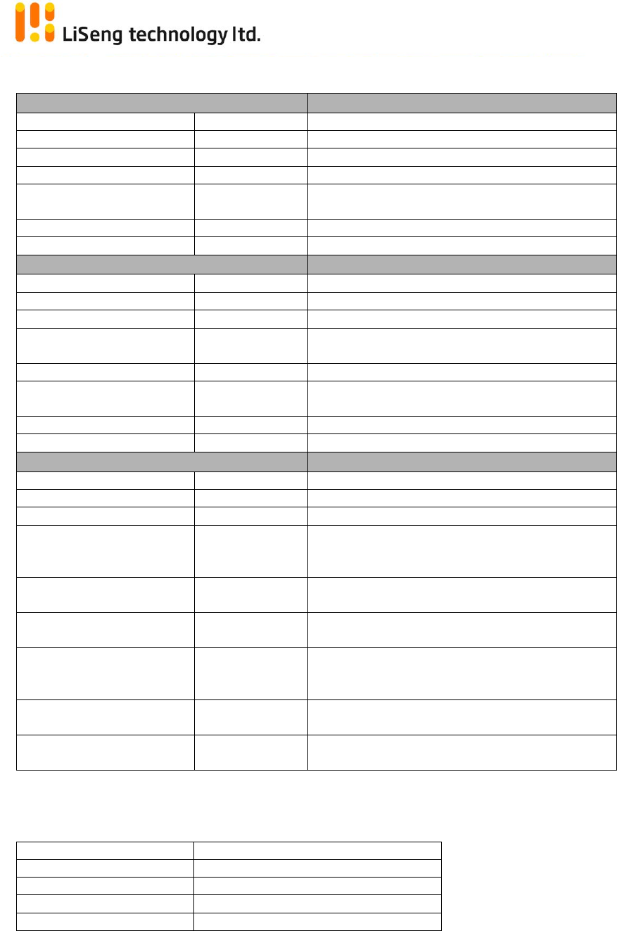
4. Electrical$Characteristics$(Module)$
Typical$DC$Characteristics$
Notes$
Deep!Sleep!current!
50nA!
!
Sleep!current!
0.7µA!
With!active!sleep!timer!!
Radio!transmit!current!!
21mA!
CPU!in!doze,!radio!transmitting!@8.5dBm!
Radio!receive!current!!
13mA!
CPU!in!doze,!radio!receiving!@0dBm!
Centre!frequency!accuracy!!
+/-25ppm!!
Additional!+/-15ppm!allowance!for!temperature!
and!ageing!!
Supply!voltage!
2.0!to!3.6V!
!
Operating!Temperature!
-40°C!to!+125°C!
Standard!range!
Typical$RF$Characteristics$
Notes$
Frequency!range!
2.4!to!2.485GHz!
!
Receive!sensitivity!!
-95dBm!!
Nominal!for!1%!PER,!as!per!802.15.4!!
Transmit!power!!
8.5dBm!!
Normal!
Maximum!receiver!input!
power!
9dBm!!
1%!PER,!measured!as!sensitivity,!supply!current!at!
14.7!mA!
RSSI!range!!
-4!to!+4!dB!!
-95!dBm!to!-10!dBm!
RF!Port!impedance!–!uFL!
connector!!
50!ohm!!
2.4!-!2.485GHz!!
Rx!Spurious!Emissions!!
-70dBm!!
Measured!conducted!into!50ohms!!
Tx!Spurious!Emissions!!
-65dBm!!
Measured!conducted!into!50ohms!!
Peripherals$
Notes$
Master!SPI!port!!
3!selects!!
Up!to!16MHz!!
Slave!SPI!port!!
Available!
Up!to!8MHz!!
Two!UARTs!!
Available!
16550!compatible!!
Two-wire!serial!I/F!
(compatible!with!SMbus!&!
I2C)!!
Available!
Up!to!400kHz!!
5!x!PWM!(4!x!timer,!1!x!
timer/counter)!!
Available!
16MHz!clock!!
Two!programmable!Sleep!
Timers!!
Available!!
32kHz!clock!!
Digital!IO!lines!(multiplexed!
with!UARTs,!timers!and!SPI!
selects)!!
20!
!
6!channel!Analogue-to-
Digital!converter!!
Available!
10-bit,!up!to!100ks/s!!
Programmable!analogue!
comparators!!
Available!
Ultra!low!power!mode!for!sleep!!
!
Antenna Specification (*For Reference Only)
Antenna plate
FPC antenna
Antenna gain
2dBi
Frequency range
2.4GHZ-2.483GHZ
POWER
0dBm
Connector type
External antenna
Living!Smart!
Page!|!6!
(*1)●Ordering!Information!
SH-IOTML①②③P-④⑤!
Designator$
Item$
Symbol$
Description$
①
Communication!Format
1!
Jennet-IP!Format!
3!
Zigbee!Format!
②!
Light!Bulb!drive!
channels!
0!
Single!Color!Light!
1!
Dual!color!Light!
2!
RGBW!color!Light!(TBD)!
③!
Version!Number!
A!
JN5168!Version!
B!
JN5169!Version!
④!
Antenna!Option!
--!
External!Antenna!model!
I!
Internal!PCB!Antenna!model!
P!
Internal!PA,!External!Antenna!model!
⑤!
Output!protocol!
--!
Jennet-IP!protocol!
L!
Zigbee!Light!Link!protocol!
H!
Zigbee!Home!Automation!1.2!protocol!
CC Statement:
This device complies with part 15 of the FCC Rules. Operation is subject to the following
two conditions: (1) This device may not cause harmful interference, and (2) this device
must accept any interference received, including interference that may cause undesired
operation.
This equipment has been tested and found to comply with the limits for a Class B digital
device, pursuant to part 15 of the FCC Rules. These limits are designed to provide
reasonable protection against harmful interference in a residential installation. This
equipment generates, uses and can radiate radio frequency energy and, if not installed
and used in accordance with the instructions, may cause harmful interference to radio
communications. However, there is no guarantee that interference will not occur in a
particular installation. If this equipment does cause harmful interference to radio or
television reception, which can be determined by turning the equipment off and on, the
user is encouraged to try to correct the interference by one or more of the following
measures:
—Reorient or relocate the receiving antenna.
—Increase the separation between the equipment and receiver.
—Connect the equipment into an outlet on a circuit different from that to which the
receiver is connected.
—Consult the dealer or an experienced radio/TV technician for help.
Caution: Any changes or modifications not expressly approved by the party responsible
for compliance could void the user's authority to operate the equipment.
This equipment complies with FCC radiation exposure limits set forth for an uncontrolled environment.
This transmitter must not be co-located or operating in conjunction with any other antenna or
transmitter.
The module is designed to comply with the FCC statement. FCC ID is RR3-SH-IOTML30BP. The host system using this
modular should have label indicated it contain modular’s FCC ID RR3-SH-IOTML30BP.
This radio module must not installed to co-locate and operating simultaneously with other radios in host system,
additional testing and equipment authorization may be required to operating simultaneously with other radio.”