Libre Wireless Technologies LS6-7620A Wireless Audio Module User Manual
Libre Wireless Technologies Inc. Wireless Audio Module
User manual
User Manual
LS6-N22S-M
SPECIFICATIONS
1.power up for MT7620A with 5V&1A
2.connect with the PC to get IP address automaticlly.
3.run the CMD on PC ,type the word "wifi" and return,then input
the IP address:10.10.10.254 and return again.
4.run the MT7620A's QA tools which given by the supplier.
5.choose the " network card" option on the UI,knock OK,then enter
operation steps for work environment.
6. The MT7620 router module with two antenna portsˈwhich
pattern is MOMI,the two antenna are the same one
The antenna manufacturer˖Dongguan City Senling Industry Co.,Ltd
Model Name˖SLA-100020108-C10
Antenna gain˖2dBi
FCC Statement˖
˖
This device complies with part 15 of the FCC Rules. Operation is
subject to the following two conditions: (1) This device may not
cause harmful interference, and (2) this device must accept any
interference received, including interference that may cause
undesired operation.
Changes or modifications not expressly approved by the party
responsible for compliance could void the user's authority to operate
the equipment.
NOTE: This equipment has been tested and found to comply with the
limits for a Class B digital device, pursuant to Part 15 of the FCC
Rules. These limits are designed to provide reasonable protection
against harmful interference in a residential installation. This
equipment generates, uses and can radiate radio frequency energy
and, if not installed and used in accordance with the instructions,
may cause harmful interference to radio communications. However,
there is no guarantee that interference will not occur in a particular
installation. If this equipment does cause harmful interference to
radio or television reception, which can be determined by turning
the equipment off and on, the user is encouraged to try to correct
the interference by one or more of the following
measures:
-- Reorient or relocate the receiving antenna.
-- Increase the separation between the equipment and receiver.
-- Connect the equipment into an outlet on a circuit different from
that to which the receiver is connected.
-- Consult the dealer or an experienced radio/TV technician for help.
FCC Radiation Exposure Statement
The modular can be installed or integrated in mobile or fix devices
only. This modular cannot be installed in any portable device, for
example, USB dongle like transmitters is forbidden.
This modular complies with FCC RF radiation exposure limits set
forth for an uncontrolled environment. This transmitter must not be
co-located or operating in conjunction with any other antenna or
transmitter. This modular must be installed and operated with a
minimum distance of 20 cm between the radiator and user body.
If the FCC identification number is not visible when the module is
installed inside another device, then the outside of the device into
which the module is installed must also display a label referring to
the enclosed module. This exterior label can use wording such as the
following: Contains Transmitter Module FCC ID: 2ADBMLS6-7620A
or Contains FCC ID: 2ADBMLS6-7620A
when the module is installed inside another device, the user manual
of this device must contain below warning statements;
1. This device complies with Part 15 of the FCC Rules. Operation is
subject to the following two conditions:
(1) This device may not cause harmful interference.
(2) This device must accept any interference received, including
interference that may cause undesired operation.
2. Changes or modifications not expressly approved by the party
responsible for compliance could void the user's authority to operate
the equipment.
The devices must be installed and used in strict accordance with the
manufacturer's instructions as described in the user documentation
that comes with the product.
http://www.rf-link.net/
3.Applications:
1.Routers 2.iNICs
3.NAS devices 4.Dual band concurrent routers
4.General Specification
Model WL-AM01B-7620A-V2.0
Product Name WLAN 11b/g/n
Major Chipset MT7620A
Standard IEEE802.11n ǃIEEE 802.11gǃIEEE 802.11b
Data Transfer
Rate
1,2,5.5,6,11,12,18,22,24,30,36,48,54,60,9
0,120 and maximum of 300Mbps
Frequency
Band 2.4GHz
Power
Consumption 3.3 V ±10% I/O supply voltage
Dimension 40.0 x 26.0 x 3.25mm (LxWxH) +-0.2MM
Hardware Supp
ort
Flash:8M (25Q64)
DDR:64M (W9751G6KB)
Ambient
Temperature
Range
-20 ~ 55 °C
Storage Conditions
The calculated shelf life in a sealed bag is 12 months if stored between 0 °C and
40 °C at less than 90% relative humidity (RH). After the bag is opened, devices that
are subjected to solder reflow or other high temperature processes must be handled in
the following manner:
Mounted within 168 hours of factory conditions, i.e. < 30 °C at 60% RH. ǂ
Storage humidity needs to maintained at < 10% RH. ǂ
Baking is necessary if the customer exposes the component to air for over 168 ǂ
hrs, baking conditions: 125 for 8 hrs.ć
http://www.rf-link.net/
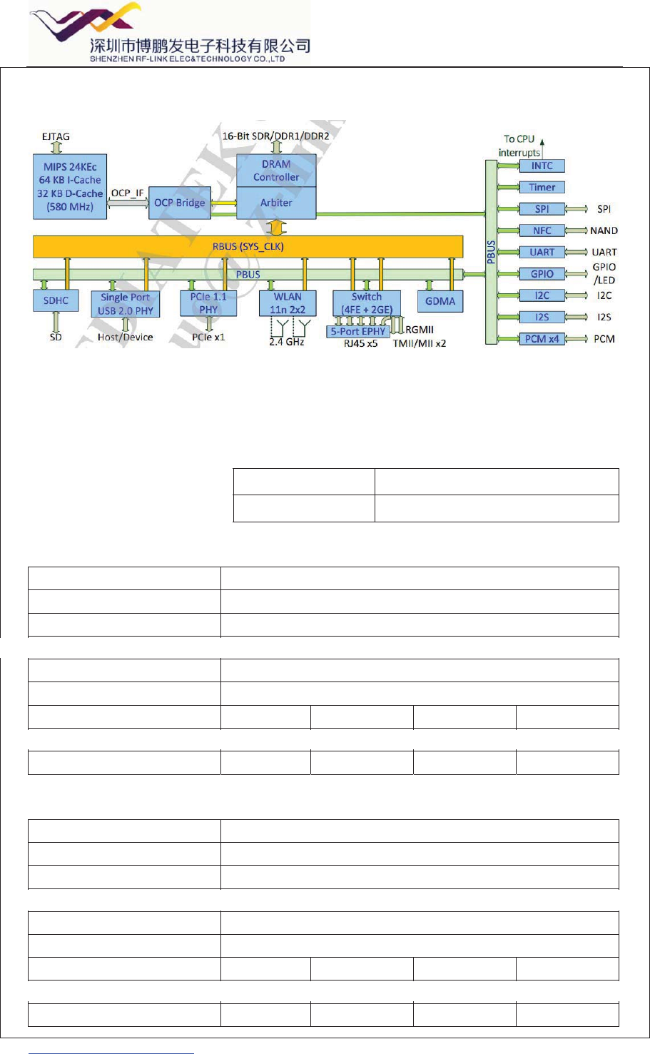
5.Block Diagram
6. Electrical Specifications
1.DC Characteristics
Module Voltage Current Consumption (linking)
WL-AM01B-7620A-V2.0 3.3V 220MA(Ϟ㔥㗙ⳟ⬉ᕅᯊⱘࡳ㗫)
2) RF Characteristics for IEEE802.11b ( 11Mbps mode unless otherwise specified)
Items Contents
Specification IEEE802.11b
Mode DSSS/CCK 11 Mbps
Channel frequency 2412 ~ 2484 MHz
RX (per) -85 dBm
FREQ ERR LIMIT f13PPM
TX Characteristics Min. Typ. Max. Unit
Power Level (17±2 dBm) 17 dBm
EVM ˄<-18˅ -18 dB
3) RF Characteristics for IEEE802.11g ( 54Mbps mode unless otherwise specified)
Items Contents
Specification IEEE802.11g
Mode OFDM 54 Mbps
Channel frequency 2412 ~ 2484 MHz
RX (per) -70 dBm
FREQ ERR LIMIT ±13PPM
TX Characteristics Min. Typ. Max. Unit
Power Level (14±2 dBm) 14 dBm
EVM (<-27) -27 dB
http://www.rf-link.net/
4) RF Characteristics for IEEE802.11n (HT20_MCS7)
Items Contents
Specification IEEE802.11n (HT20_MCS7)
Mode HT20_MCS7 65 Mbps
Channel frequency 2412 ~ 2484 MHz
RX (per) -65 dBm
FREQ ERR LIMIT ±13PPM
TX Characteristics Min. Typ. Max. Unit
Power Level (13±2dBm) 13 dBm
EVM -28 dB
5) RF Characteristics for IEEE802.11n (HT40_MCS7)
Items Contents
Specification IEEE802.11n (HT40_MCS7)
Mode HT40_MCS7 135 Mbps
Channel frequency 2412 ~ 2484 MHz
RX (per) -65 dBm
FREQ ERR LIMIT ±13PPM
TX Characteristics Min. Typ. Max. Unit
Power Level (13±12 dBm) 13 dBm
EVM (<-28) -28 dB
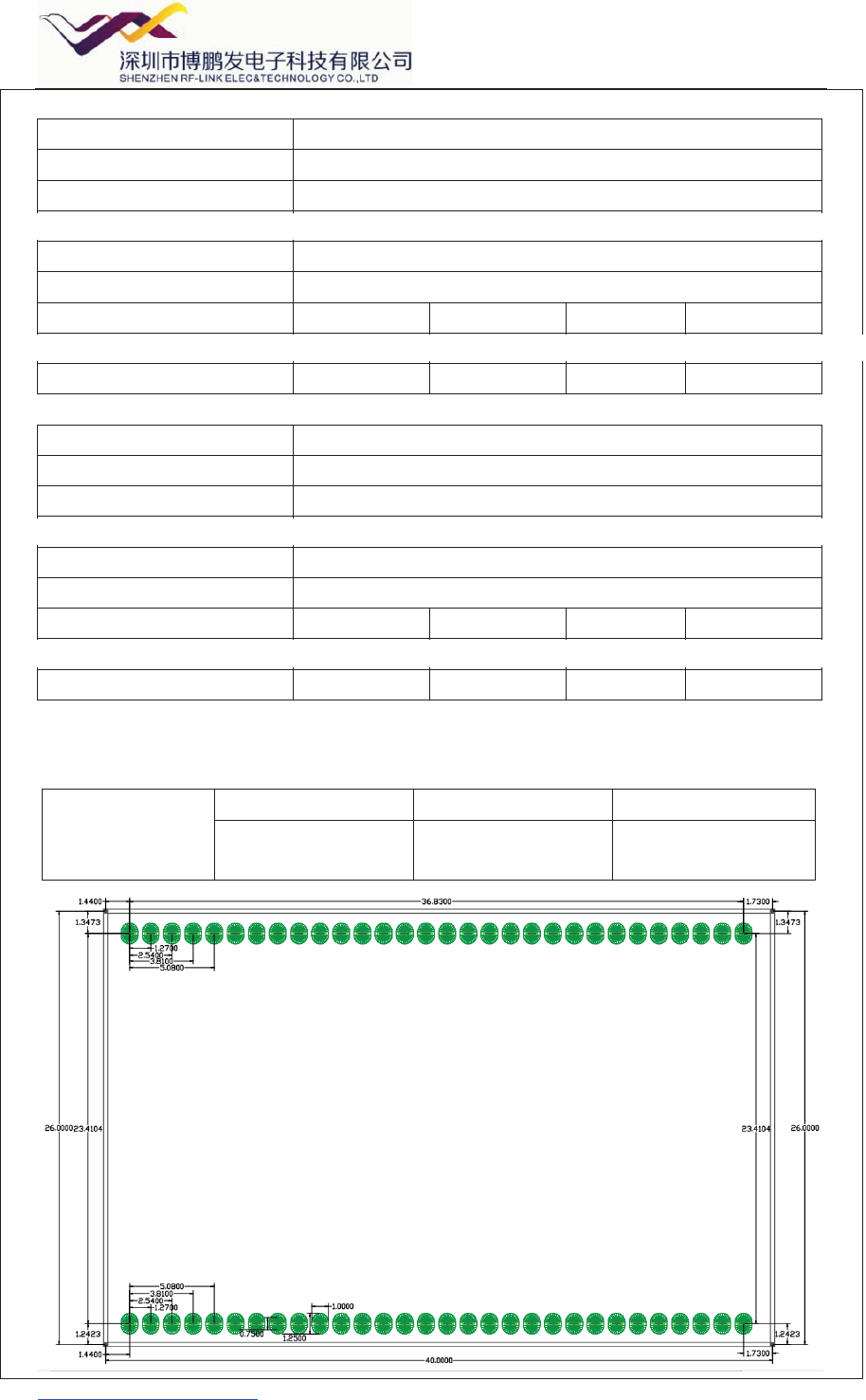
7.Mechanical
Dimensions
(mm)
Length Width Height
40.0 26.0 3.25
(Tolerance:±0.2mm) (Tolerance:±0.2mm) (Tolerance:±0.2mm)
http://www.rf-link.net/
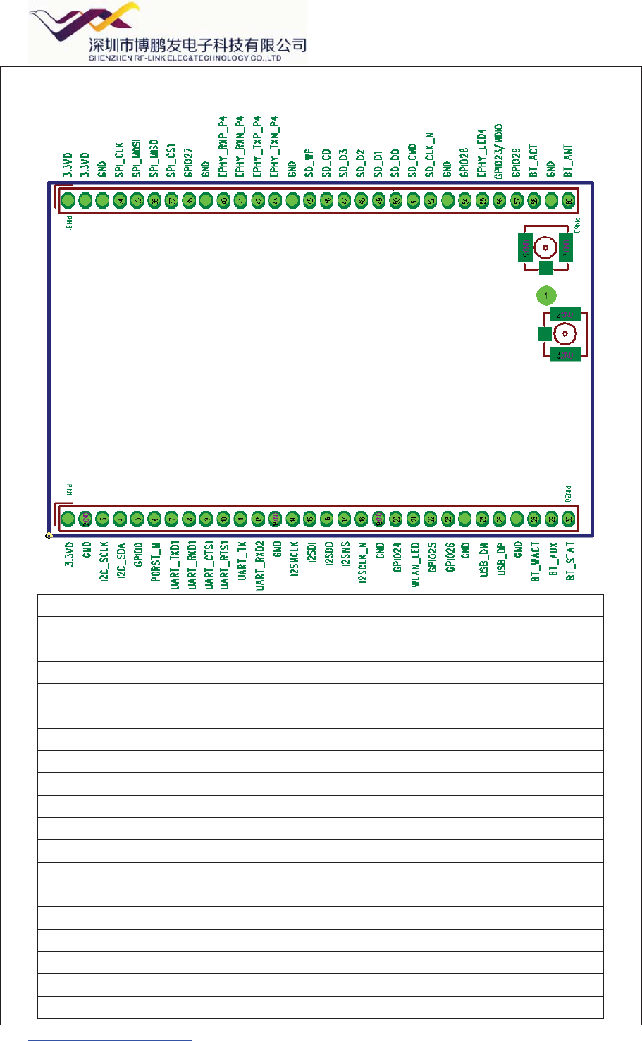
8.Module Pin Assignment
Pin Function Description
1 3.3VD 3.3VD
2 GND Ground
3 I2C_SCLK I2C_SCLK
4 I2C_SDA I2C_SDA
5 GPIO0 GPIO0
6 PORST_N PORST_N
7 UART_TXD1 UART_TXD1
8 UART_RXD1 UART_RXD1
9 UART_CTS1 UART_CTS1
10 UART_RTS1 UART_RTS1
11 UART_TX UART_TX
12 UART_RXD2 UART_RXD2
13 GND Ground
14 I2SMCLK I2SMCLK
15 I2SDI I2SDI
16 I2SDO I2SDO
17 I2SWS I2SWS
18 I2SCLK_N I2SCLK_N
http://www.rf-link.net/
19 GND Ground
20 GPIO24 GPIO24
21 WLAN_LED WLAN Activity LED
22 GPIO25 GPIO25
23 GPIO26 GPIO26
24 GND Ground
25 USB_DM USB_D-
26 USB_DP USB_D+
27 GND Ground
28 BT_WACT GPIO
29 BT_AUX GPIO
30 BT_STAT GPIO
31 3.3VD 3.3VD
32 3.3VD 3.3VD
33 GND Ground
34 SPI_CLK SPI_CLK
35 SPI_MOSI SPI_MOSI
36 SPI_MISO SPI_MISO
37 SPI_CS1 SPI_CS1
38 GPIO27 GPIO
39 GND Ground
40 EPHY_RXP_P4 Port4 RX+
41 EPHY_RXN_P4 Port4 RX-
42 EPHY_TXP_P4 Port4 TX+
43 EPHY_TXN_P4 Port4 TX-
44 GND Ground
45 SD_WP SD_WP
46 SD_CD SD_CD
47 SD_D3 SD_D3
48 SD_D2 SD_D2
49 SD_D1 SD_D1
50 SD_D0 SD_D0
51 SD_CMD SD_CMD
52 SD_CLK_N SD_CLK_N
53 GND Ground
54 GPIO28 GPIO
55 EPHY_LED4 Port4_LED
56 GPIO23/MDIO GPIO
57 GPIO29 GPIO
58 BT_ACT GPIO
59 GND Ground
60 BT_ANT BT_ANT
http://www.rf-link.net/
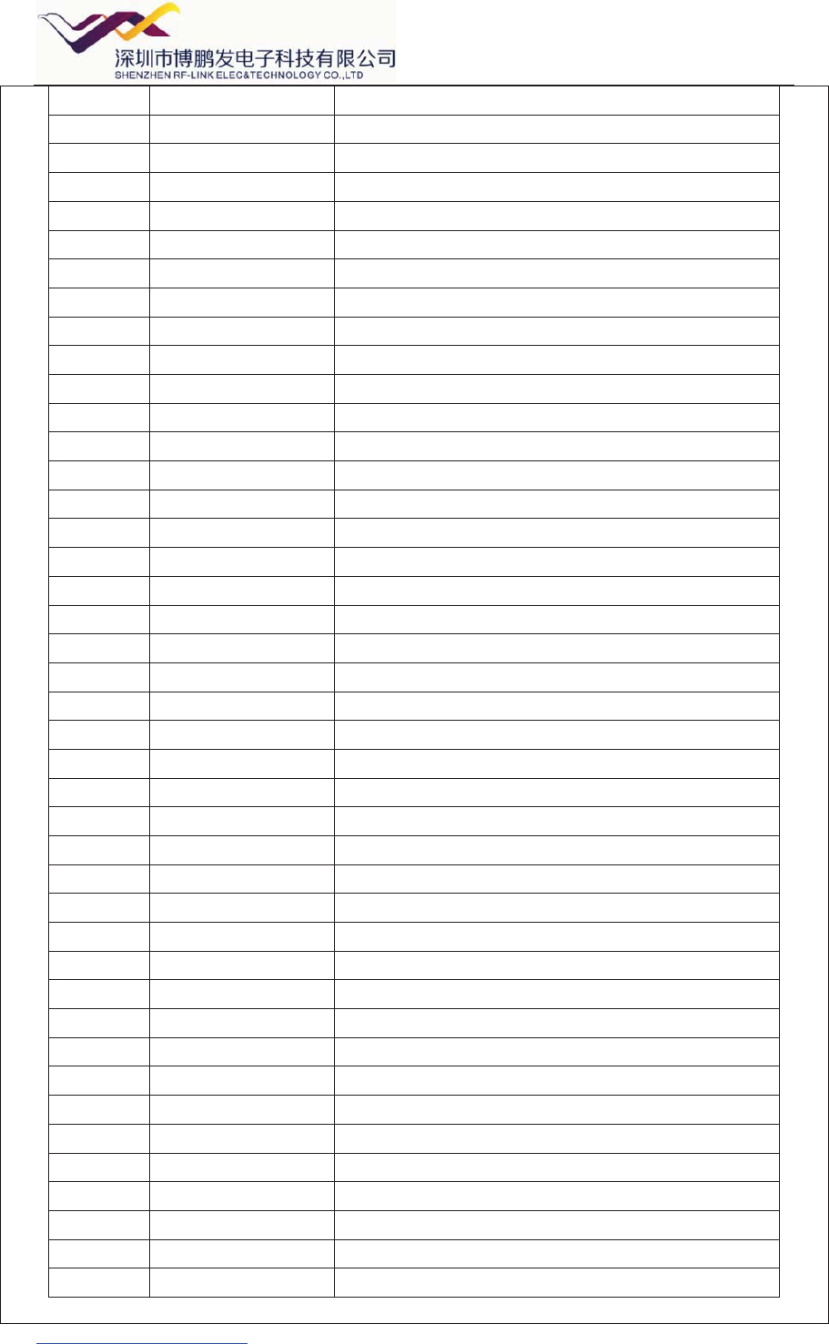
The picture of top
The picture of bottom
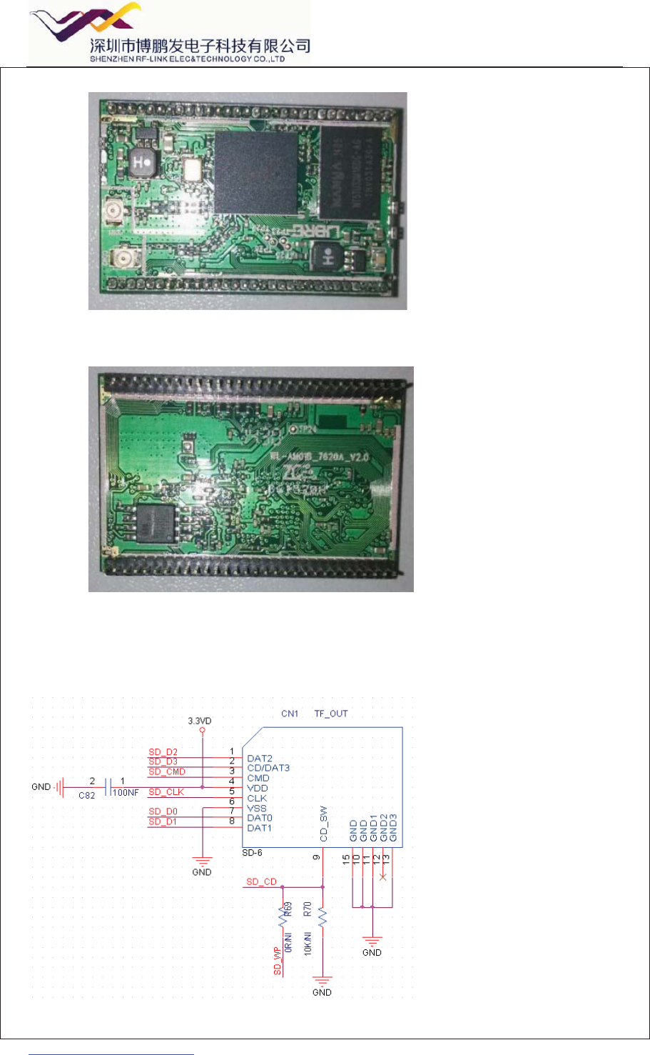
9.Circuit reference pictures
1.SD part reference.
http://www.rf-link.net/
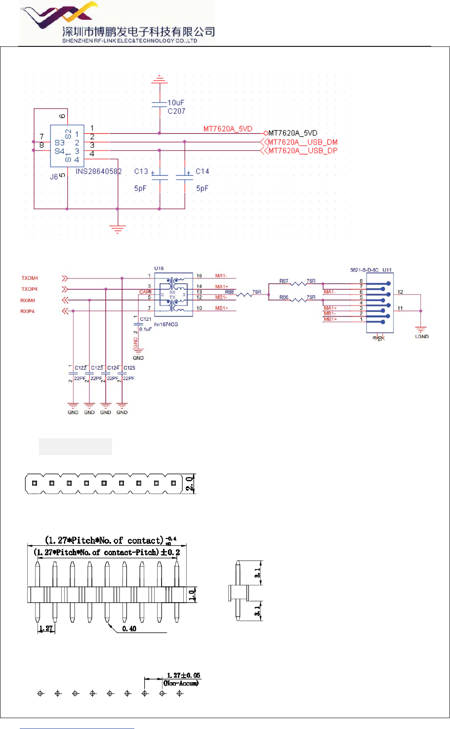
2.USB part reference circuit.
3.
10.Pin Header