Liebert 272014 Users Manual Hiline Slim
272014 to the manual ba43b939-10bd-4fe2-85cd-c1f7fbd9019c
2015-02-09
: Liebert Liebert-272014-Users-Manual-571305 liebert-272014-users-manual-571305 liebert pdf
Open the PDF directly: View PDF ![]() .
.
Page Count: 34
Hiline Slim
English
Italiano
Issued by TDS
cod. 272014 - rev. 12.01.2001
Service Manual
Manuale di Assistenza

page 1 English
Caution
It is recommended that:
the manual is retained for the entire service life of the machine;
the user reads the manual carefully before carrying out any operations on the machine;
the machine is used exclusively for the purpose for which it is intended; incorrect use of the machine shall release
the manufacturer from any liability.
This manual has been prepared to enable the end-user to carry out only the operations that can made with the pan
els closed. Any operations that require the opening of doors or equipment panels must be carried out only by quali
fied personnel.
Each machine is equipped with an Electric Insulating device which allows the operator to work in conditions of
safety. This device must always be used to eliminate risks during maintenance (electric shocks, scalds, automatic
restarting, moving parts and remote control).
The panel key supplied with the unit must be kept by the person responsible for maintenance.
For identification of the unit (model and serial no.) in case of the necessity for assistance or spare parts, read the
identification label placed on the outside and inside of the unit.
IMPORTANT: this manual may be subject to modification; for complete and up-to-date information the user
should always consult the manual supplied with the machine.
Index
1 - Preliminary operations 2. . . . . . . . . . . . . . . . . . . . . . . . . . . . . . . . . . . . . . . . . . . . . . . . . . . . . . . . . . . . . . . . . . . . . . . . . . . . . . . . . . . . . . . .
1.1 - Foreword 2. . . . . . . . . . . . . . . . . . . . . . . . . . . . . . . . . . . . . . . . . . . . . . . . . . . . . . . . . . . . . . . . . . . . . . . . . . . . . . . . . . . . . . . . . . . . . . . . . . . .
1.2 - Operating limits 2. . . . . . . . . . . . . . . . . . . . . . . . . . . . . . . . . . . . . . . . . . . . . . . . . . . . . . . . . . . . . . . . . . . . . . . . . . . . . . . . . . . . . . . . . . . . . .
1.3 - Sound pressure levels 2. . . . . . . . . . . . . . . . . . . . . . . . . . . . . . . . . . . . . . . . . . . . . . . . . . . . . . . . . . . . . . . . . . . . . . . . . . . . . . . . . . . . . . . . . .
1.4 - Sealing the room 2. . . . . . . . . . . . . . . . . . . . . . . . . . . . . . . . . . . . . . . . . . . . . . . . . . . . . . . . . . . . . . . . . . . . . . . . . . . . . . . . . . . . . . . . . . . . . .
1.5 - Inspection 2. . . . . . . . . . . . . . . . . . . . . . . . . . . . . . . . . . . . . . . . . . . . . . . . . . . . . . . . . . . . . . . . . . . . . . . . . . . . . . . . . . . . . . . . . . . . . . . . . . .
1.6 - Transport 2. . . . . . . . . . . . . . . . . . . . . . . . . . . . . . . . . . . . . . . . . . . . . . . . . . . . . . . . . . . . . . . . . . . . . . . . . . . . . . . . . . . . . . . . . . . . . . . . . . . .
1.7 - Positioning of air conditioner 2. . . . . . . . . . . . . . . . . . . . . . . . . . . . . . . . . . . . . . . . . . . . . . . . . . . . . . . . . . . . . . . . . . . . . . . . . . . . . . . . . . . .
1.8 - Service area 2. . . . . . . . . . . . . . . . . . . . . . . . . . . . . . . . . . . . . . . . . . . . . . . . . . . . . . . . . . . . . . . . . . . . . . . . . . . . . . . . . . . . . . . . . . . . . . . . .
1.9 - Wall holes 2. . . . . . . . . . . . . . . . . . . . . . . . . . . . . . . . . . . . . . . . . . . . . . . . . . . . . . . . . . . . . . . . . . . . . . . . . . . . . . . . . . . . . . . . . . . . . . . . . . .
2 - Installation 3. . . . . . . . . . . . . . . . . . . . . . . . . . . . . . . . . . . . . . . . . . . . . . . . . . . . . . . . . . . . . . . . . . . . . . . . . . . . . . . . . . . . . . . . . . . . . . . . . . . .
3 - Electrical and kit connections 4. . . . . . . . . . . . . . . . . . . . . . . . . . . . . . . . . . . . . . . . . . . . . . . . . . . . . . . . . . . . . . . . . . . . . . . . . . . . . . . . .
3.1 - Electrical connections 4. . . . . . . . . . . . . . . . . . . . . . . . . . . . . . . . . . . . . . . . . . . . . . . . . . . . . . . . . . . . . . . . . . . . . . . . . . . . . . . . . . . . . . . . . .
3.2 - Emergency cooling kit (optional) 4. . . . . . . . . . . . . . . . . . . . . . . . . . . . . . . . . . . . . . . . . . . . . . . . . . . . . . . . . . . . . . . . . . . . . . . . . . . . . . . . .
4 - Start-up 5. . . . . . . . . . . . . . . . . . . . . . . . . . . . . . . . . . . . . . . . . . . . . . . . . . . . . . . . . . . . . . . . . . . . . . . . . . . . . . . . . . . . . . . . . . . . . . . . . . . . . . .
4.1 - First start-up (or after long halt) 5. . . . . . . . . . . . . . . . . . . . . . . . . . . . . . . . . . . . . . . . . . . . . . . . . . . . . . . . . . . . . . . . . . . . . . . . . . . . . . . .
4.2 - Start-up with low outside temperature 5. . . . . . . . . . . . . . . . . . . . . . . . . . . . . . . . . . . . . . . . . . . . . . . . . . . . . . . . . . . . . . . . . . . . . . . . . . .
4.3 - Starting and stopping 5. . . . . . . . . . . . . . . . . . . . . . . . . . . . . . . . . . . . . . . . . . . . . . . . . . . . . . . . . . . . . . . . . . . . . . . . . . . . . . . . . . . . . . . . . .
5 - Operation 5. . . . . . . . . . . . . . . . . . . . . . . . . . . . . . . . . . . . . . . . . . . . . . . . . . . . . . . . . . . . . . . . . . . . . . . . . . . . . . . . . . . . . . . . . . . . . . . . . . . . . .
5.1 - Adjustment of the condenser fan speed 6. . . . . . . . . . . . . . . . . . . . . . . . . . . . . . . . . . . . . . . . . . . . . . . . . . . . . . . . . . . . . . . . . . . . . . . . . . . .
5.2 - Emergency cooling (optional) 6. . . . . . . . . . . . . . . . . . . . . . . . . . . . . . . . . . . . . . . . . . . . . . . . . . . . . . . . . . . . . . . . . . . . . . . . . . . . . . . . . . .
6 - Microprocessor controls 6. . . . . . . . . . . . . . . . . . . . . . . . . . . . . . . . . . . . . . . . . . . . . . . . . . . . . . . . . . . . . . . . . . . . . . . . . . . . . . . . . . . . . . .
6.1 - Control logic 6. . . . . . . . . . . . . . . . . . . . . . . . . . . . . . . . . . . . . . . . . . . . . . . . . . . . . . . . . . . . . . . . . . . . . . . . . . . . . . . . . . . . . . . . . . . . . . . . .
7 - Refrigerant R22 and oil charge 7. . . . . . . . . . . . . . . . . . . . . . . . . . . . . . . . . . . . . . . . . . . . . . . . . . . . . . . . . . . . . . . . . . . . . . . . . . . . . . . .
7.1 - Features of the refrigerating fluid R22 7. . . . . . . . . . . . . . . . . . . . . . . . . . . . . . . . . . . . . . . . . . . . . . . . . . . . . . . . . . . . . . . . . . . . . . . . . . . .
7.2 - Refrigerant charge 7. . . . . . . . . . . . . . . . . . . . . . . . . . . . . . . . . . . . . . . . . . . . . . . . . . . . . . . . . . . . . . . . . . . . . . . . . . . . . . . . . . . . . . . . . . . .
7.3 - Oil charge 8. . . . . . . . . . . . . . . . . . . . . . . . . . . . . . . . . . . . . . . . . . . . . . . . . . . . . . . . . . . . . . . . . . . . . . . . . . . . . . . . . . . . . . . . . . . . . . . . . . .
8 - Calibrations 8. . . . . . . . . . . . . . . . . . . . . . . . . . . . . . . . . . . . . . . . . . . . . . . . . . . . . . . . . . . . . . . . . . . . . . . . . . . . . . . . . . . . . . . . . . . . . . . . . . .
9 - Maintenance 9. . . . . . . . . . . . . . . . . . . . . . . . . . . . . . . . . . . . . . . . . . . . . . . . . . . . . . . . . . . . . . . . . . . . . . . . . . . . . . . . . . . . . . . . . . . . . . . . . . .
9.1 - Dismantling the unit 9. . . . . . . . . . . . . . . . . . . . . . . . . . . . . . . . . . . . . . . . . . . . . . . . . . . . . . . . . . . . . . . . . . . . . . . . . . . . . . . . . . . . . . . . . . .
10 - Fault finding / alarms 10. . . . . . . . . . . . . . . . . . . . . . . . . . . . . . . . . . . . . . . . . . . . . . . . . . . . . . . . . . . . . . . . . . . . . . . . . . . . . . . . . . . . . . . . . .
11 - Spare parts 12. . . . . . . . . . . . . . . . . . . . . . . . . . . . . . . . . . . . . . . . . . . . . . . . . . . . . . . . . . . . . . . . . . . . . . . . . . . . . . . . . . . . . . . . . . . . . . . . . . . .
page 2
English 272014 - 04.02.2000
1 - Preliminary operations
1.1 - Foreword
The following manual describes the installation, opera
tion and maintenance of Air Conditioners, series Hiline
Slim (see Fig. 1).
IMPORTANT:
Also consult the manual for the Microface microproces
sor control supplied with the machine (if installed).
1.2 - Operating limits
The units are designed to operate within working ranges
(see Tab. 1).
These limits are referred to new machines or for those
that have been correctly installed and serviced.
The warranty clauses are no longer valid for any damage
or malfunction that may occur during or due to opera
tion outside the application values.
Tab. 1 - Operating limits
Power supply voltage
230 V 10%/1/50 Hz
Power supply voltage
24/48 30% Vdc with INVERTER
Outdoor conditions
da: -10C (-30C with VARIEX)
Outdoor conditions a: 43C
Indoor conditions with
operating compressor
da: 20C 30% R.H. e 20C 80%
R.H.
operating compressor a: 35C, 40% R.H.
Storage conditions
da: -25C, 5% R.H.
Storage conditions a: 55C, 90% R.H.
External side protection
degree IP 24
1.3 - Sound pressure levels
Tab. 2 shows, for the internal and the external side, the
maximum sound pressure levels of the units in standard
configuration, in continuous operation, at 2 m from the
front surface of the machine, at 1 m height in free field
conditions. The noise levels have the highest values at
the front of the unit, on the internal side.
1.4 - Sealing the room
To create stable indoor conditions make sure that the
room is airtight by sealing all gaps, cable entries, etc...
1.5 - Inspection
On receiving the equipment immediately inspect its
condition; report any damage to the transport company
at once.
1.6 - Transport
Always keep the unit vertically upright.
If possible transport the unit using a fork lift truck;
otherwise use a crane with belts or cables, avoiding
the exerting of pressure on the top edges of the pack
ing.
Unpack the unit as close as possible to its installation
position. Once unpacked, avoid stress being trans
mitted to its internal components.
1.7 - Positioning of air conditioner
The air conditioner can be installed in any indoor
location where it is not exposed to an aggressive
ambient.
Position the air conditioner so as to ensure optimum
air distribution within the area in which it is to oper
ate, preventing the creation of unconditioned zones.
For the correct positioning of the air conditioner see
Fig. 2 at the end of the manual.
1.8 - Service area
The unit must be provided with a suitable Service Area,
as follows (see Fig. 2):
All ordinary maintenance can be performed both
from the front side and from the rear side (external)
where a minimum area must be left free of obstruc
tions.
1.9 - Wall holes
Make the holes in the wall of the container next to the
unit's position (see Fig. 3).

page 3 English
Tab. 2 - Sound pressure levels
Model
Octave band frequency (Hz) Sound
pressure
ll
M
o
d
e
l
31.5 63 125 250 500 1000 2000 4000 8000
p
level
[dB(A)]
PKS3
Indoor, free field at 2 m
in front of the unit 49 56 62 58 55 54 53 53 51 61
PKS3
Outdoor, free field at
2 m in front of the unit 50 51 49 54 51 51 47 44 37 55
PKS4
Indoor, free field at 2 m
in front of the unit 49 56 62 58 55 54 53 53 51 61
PKS4
Outdoor, free field at
2 m in front of the unit 50 51 49 54 51 51 47 44 37 55
2 - Installation
For a correct installation proceed as follows (Fig. 4):
Provide the unit with cornice protection elements
(these can be supplied as optional), using the proper
holes and the self-tapping screws with 3.5 mm diam
eter.
In order to avoid that water filters inside the contain
er, provide it with an adhesive rubber gasket.
Fix the cornice to the shelter wall by means of M4
screws with anchor.
Fix the lower cornice protection element by means of
two M4 screws with anchor.
Provide the unit roof with the fixing bracket to the
wall with two self-tapping screws with 3.5 mm diam
eter.
3 - Electrical and kit connections
Before performing any operations on the electric parts,
make sure that:
all electrical components are undamaged;
all terminal screws are tight;
the supply voltage and frequency are as indicated on
the unit;
the switch QS1 is in open position (OFF);
the automatic switch QS2 on the outer clamps of the
inverter (if installed) are off;
there are no components under voltage.
3.1 - Electrical connections
(see the wiring diagram)
The electrical connections (power supply 230/1/50 and,
for emergency power supply (48 and 24 Vdc) will be car
ried out from the roof of the unit by means of some pro
per holes.
Let the electrical power supply cable (not supplied by
us), pass through the hole made on the unit roof.
Note: For the power supply use a screened cable
(minimum section indicated in Tab. 4).
It is advisable to keep the mains power supply cable
as far as possible from the other cables coming out of
the inverter (optional).
Connect the 230V/1/50 Hz line to the main switch
QS1 placed inside the electrical panel.
Concerning the alarm contacts available in the differ
ent versions, these can be found on the terminal
board in the electrical panel.
For the alarm description see Chapter 6 and the
manual of the installed control.
To connect 2 or more units installed in the same con
tainer and provided with the MICROFACE control,
with HIROMATIC interface, use the HIROBUS
cable (supplied with the unit) by connecting it as
shown in the wiring diagram. See the Microface and
Hiromatic manual for the configuration of the
Stand-by units.
page 4
English 272014 - 04.02.2000
Tab. 3 - Standard electrical features
Evaporator fan Condenser fan Compressor Heater
(2 x unit)
OA FLA LRA Nom. power
[W]
OA FLA LRA Nom. power
[W]
OA
(*)
FLA LRA Nom. power
[W] (*)
OA FLA LRA Nom. power
[W]
PKS3 1 - - 200 1.5 - - 340 5.9 10 34 1370 - 13 - 3000
PKS4 1 - - 200 1.5 - - 340 7.1 12 36.5 1700 - 13 - 3000
(*) In the following conditions (ARI 520-78):
Condensing temperature 54.4C,
Ambient temp. 35C,
Evaporation temp. 7.2C,
Sub-cooling temp.: 8.3C
Overheating temp.: 11C
Tab. 4 - Protection switch and cable sizing
Protection switch with differential current In = 0.3A Cable sizing
V230/1/50Hz 230 Vac 24/48Vdc
PKS3-PKS4
20A
4mm
2
4mm
2
PK
S3
-PK
S4
20A
4
mm
2
4
mm
2
3.2 - Emergency cooling kit
(optional)
The emergency cooling kit consists of an inverter and a
single-phase transformer installed inside the electric
board.
Operating as shown in par. 3.1, supply power up to 48
(24) Vdc inside the electrical panel, by means of a
screened cable with a minimum section as shown in
Tab. 4. Connect the possible ground line to the positive
pole of the 48 Vdc power supply. Connect the cable
screening to the metal cable clamp and perform the con
nections following the wiring diagram carefully.
Attention: Connect the poles correctly.
As regards the units with emergency supply through
external Inverter, make the connections as specified in
the electrical diagram.
4 - Start-up
4.1 - First start-up (or after a long halt)
Before starting the air conditioner do check if the power
supply voltage and frequency comply with those indi
cated on the identification plate of the unit.
After that, the conditioner can be started putting the
automatic switch QS1 to ON position. On the units pro
vided with this switch also press the ON-OFF push but
ton on the Hiromatic interface.
Check the electrical input of all components and
compare it with the data shown in the Tab. 3. Check that
there are no active alarms; wait until the system reaches
the standard operation and then make the following
checks:
check that the fans are working correctly;
make sure that the temperature is guaranteed and
the compressor and the heaters (optional) work
when required;
only on versions provided with the Variex option (speed
adjustment)make sure that the speed adjuster of the
fan of the condensing section is correctly calibrated
and controls the fan operation (see chapter 8).
4.2 - Start-up with low outside temperature
In case of low outside temperature (<0C), the unit
start-up is helped by the delay time of the low pressure
alarm activation, within which the pressures in the refrig
erating circuit reach the standard operation values.
4.3 - Starting and stopping
For the units provided with HIROMATIC interface:
start the unit by pressing the ON-OFF push button
on the Hiromatic (confirmed by SYS.ON on the
display);
stop the unit by pressing the ON-OFF push button
on the Hiromatic (confirmed by SYS.OFF. on the
display).
Note: turn the main switch QS1 and the QS2 Inverter
switch off only if the unit is stopped for a long time.
For the units provided with the Microface control, you
can switch on/off using the main switch QS1, which is ac
cessible by opening the hinged higher panel acting on
quick lock system.

page 5 English
5 - Operation
The unit operation is completely automatic.The below
sequence explains (with the assistance of Fig. 5 - Opera
tion diagram) how the unit operates (see also Fig. 6
Refrigerating circuit):
1) The temperature sensor, positioned inside the shel
ter, informs the control about the condition of the air
to be conditioned.
2) The control compares the received information with
the Set Point values (= min. indoor temperature
required) and Differential programmed values, pre
setting the air conditioner for the air conditioning
with the following modes:
Cooling (Fig. 5)
The compressor (9) and the fans (6) and (10) are started
up when the temperature of the room to be conditioned
exceeds the preset value. The intake air from the centrif
ugal fan (6) enters the unit through the lower gap (A),
goes immediately through the filter (1) and then the
evaporator (5).
The cool refrigerant flows through the evaporator (5),
thus cooling the air passing through it. The conditioned
air is conveyed into the conditioned room through the
discharge opening (B).
The heat taken from the room and the one generated by
the conditioner motor operation are disposed through
the condenser (11) placed in the lower part of the unit
and hit, thanks to the fan (11), by the outside air. The fan
operation is managed in ON - OFF mode (or with
Variex, see par. 5.1) as a function of the condensing pres
sure.
For the operation logics of the control see chapter 6.
Heating (optional)
The air heating is achieved by means of electric heaters
(7), located in the air flow and activated according to the
logics set on the control (see chapter 6).
The manual reset of the safety thermostat (15), placed
on the electrical heaters is carried out throught the front
after removing the grill panel.
Cooling in Freecooling (optional) - (Fig. 5)
When the outside air temperature is lower than the
inside air temperature by some degrees, it is possible to
use this difference to refresh the shelter inside part by
direct intake of the outside air, i.e. without using the
compressor. Thus it is possible to achieve a considerable
energy saving.
When the expected conditions occur, the servo-control
(2), managed by the Microface control, opens the mov
ing damper (12) separating the flows of the inside air and
outside air. In this way the outside air sucked by the fans
(6) flows inside the container and is discharged through
the openings of the condensing section. The air flows
present in this operation mode are shown in Fig. 5).
The opening degree of the damper is determined as a
function of the set point value to be kept and of the
intake air temperature (see chapter 6).
5.1 - Adjustment of the condenser fan speed
(compulsory for outside temperatures
-10 / -30C)
A sensor is positioned so as to detect constantly the con
densing pressure of the refrigeration gas. On the basis of
this information, an electronic device (Variex) adjusts
the fan rotation speed in order to keep the condensing
pressure within the allowed values. In this way, besides
optimizing the compressor operation, you can have a
remarkable reduction of the sound pressure level
(mainly during the night), an easier start-up of the com
pressor at low temperatures and some energy saving.
For the calibration of the speed adjuster refer to chapter
8.
5.2 - Emergency cooling
(optional)
This option is available for all those applications where it
is mostly important to guarantee air flow inside the shel
ter, even in the event of mains current drop. In this case,
by an inverter and a transformer, the units can be sup
plied by the emergency coils at 24 or 48 V dc (see Fig. 7).
The intervention mode of the emergency system
depends on the switch QS1 condition:
QS1 = ON
If the main power supply is not cut out, the emer
gency system remains inactive;
if there is no voltage on the main power supply line,
the inverter is automatically activated and, being sup
plied by the emergency coils at 24/48 V dc, by the
24/48 V / 230 V transformer it supplies the fan of the
evaporating section and the electronic control. So all
functions of the unit are still managed, allowing the
inside air to recirculate (or the outside air to come in,
if the unit is provided with freecooling) if the temper
ature inside the shelter is not within the permitted
range. In this operation mode, a relay contact (KM6)
signals the activation of the inverter system.
If the voltage of the emergency coils goes below the
safety value, the inverter system is automatically de-
activated.
QS1 = OFF
In this abnormal condition occurring, for instance,
after a short-circuit in the unit the inverter is auto
matically de-activated.
CAUTION:
For safety reasons do disconnect the automatic switch
QS2 when you want to stop the unit.
page 6
English 272014 - 04.02.2000
6 - Microprocessor controls
The machine is available in four different operating con
figurations:
1) chill unit only;
2) chill and hot unit;
3) unit with freecooling, chill only;
4) unit with freecooling, chill and hot.
All versions are equipped with the new Microface
microprocessor control.
6.1 - Control logic
These units are managed by the Microface microproces
sor control and may be combined with the Hiromatic
control for the complete monitoring of all unit operation
parameters (see enclosed manual).
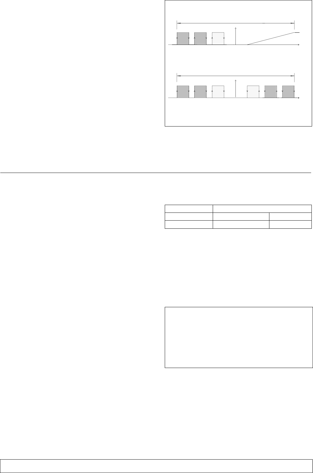
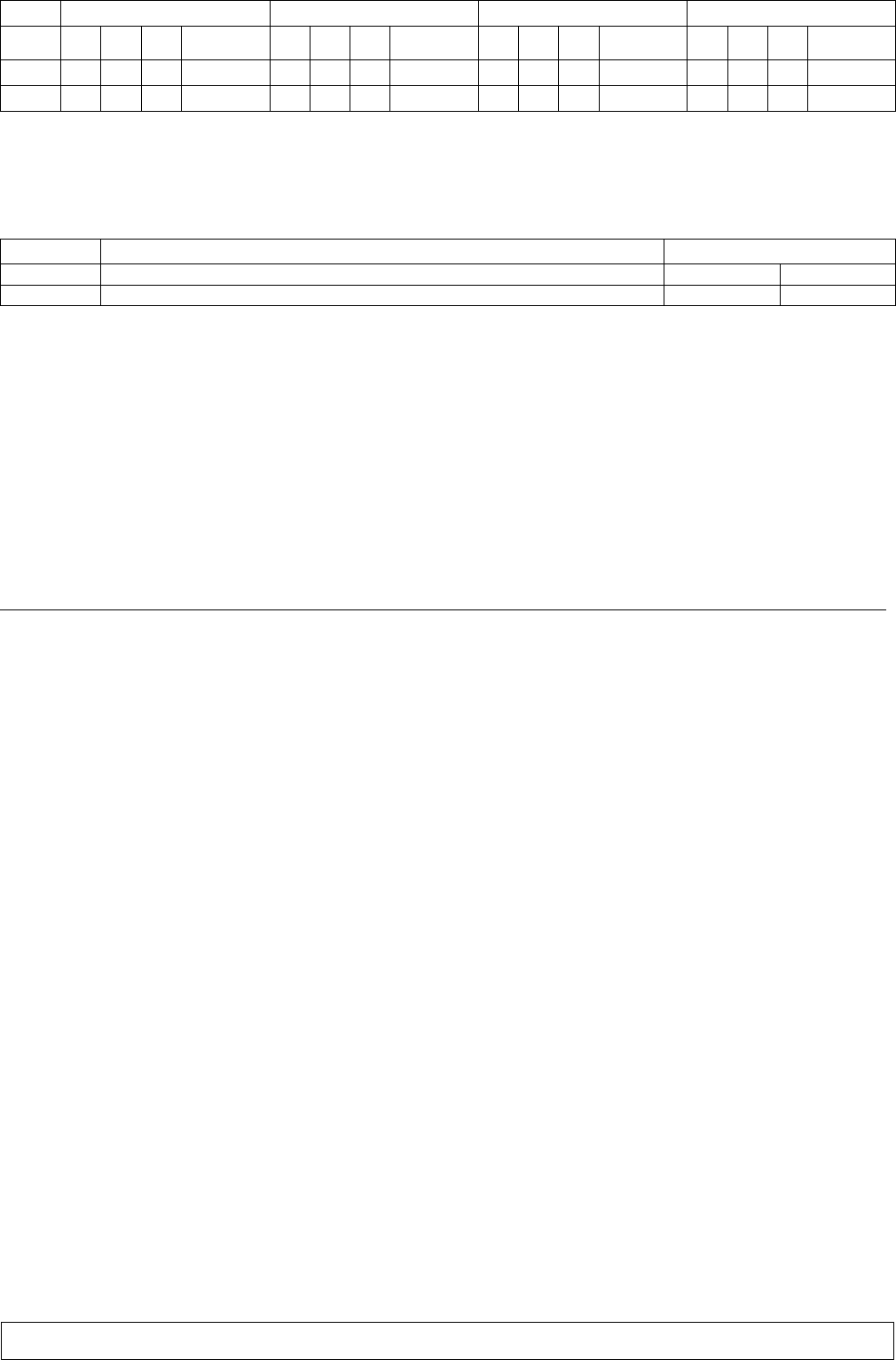
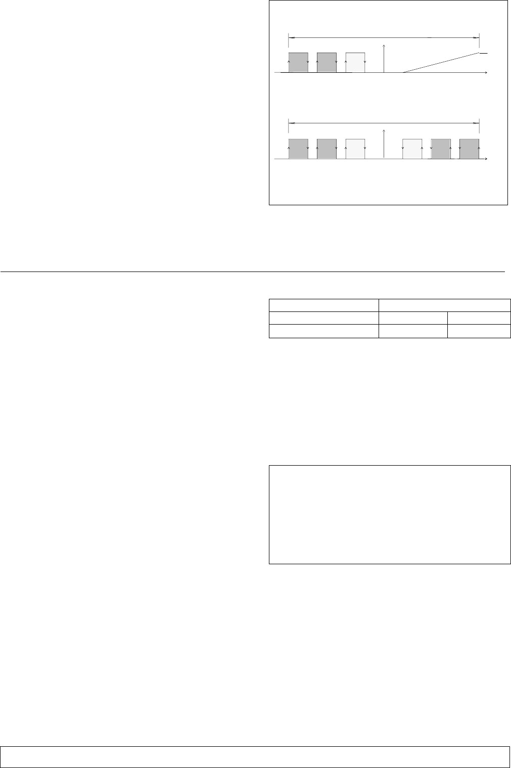
The control algorithm is based on a single-stage adjust
ment for the heating and cooling with the compressor
and on an adjustment of the proportional-integrative
type for the cooling in the Freecooling mode, with setting
of the set point and proportional band (P) (Fig. d.)
The control manages all activation delays of the com
pressor, and minimum times, in order to guarantee the
proper operation and to extend its life as much as pos
sible.
The activation of the Freecooling mode occurs as a func
tion of the difference (that can be set) between the inside
temperature and the outside temperature. This means
that if the difference between the 2 temperatures
increases beyond a certain value, the unit automatically
passes to the Freecooling function: the compressor is
de-activated and the analog output controls the
3-point servomotor of the damper. The damper open
ing is varied in order to maintain the inside temperature
equal to setpoint and as a function of the intake air tem
perature, which cannot be lower than a preset safety
value.
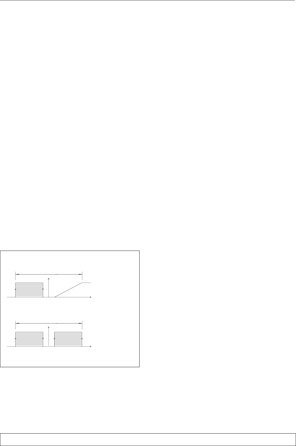
Fig. a Compressor, heater and damper opening opera
tion
Set CoolingHeating C
Set CoolingHeating C
Freecooling
mode
Compressor
cooling mode
P Band
P Band
If the inside temperature exceeds the proportional band
by more than 20% for longer than 10 minutes, the unit
passes to the cooling with compressor and the Freecool
ing mode remains de-activated for 1/2 hour. If the inside
temperature exceeds the proportional band by more
than 50%, the Freecooling mode is immediately de-
activated and remains in this condition for 1/2 hour and
the cooling by refrigerating compressor intervenes.
6.1.1 - Start-Stop
Altogether there are three ways for starting or stopping
the unit:
a) the isolator switch inside the electrical panel;
b) the digital input of the Microface card;
c) the ON-OFF push button on the Hiromatic interface
(optional).
Priority: a) b) c) must be considered as 3 series contacts;
only if all contacts are on, the unit can operate.
6.1.2 - Alarm control
The terminal board of the elertical panel is provided with
2 clean exchange contacts, on standard configuration,
used as follows:
1) General alarm:
compressor low pressure
compressor high pressure (reset on the pressure
switch)
sensor fault
memory fault
fan fault (with optional sensors)
2) General warning - signalling of various failure
conditions, among which:
high temperature
low temperature
heater thermostat (reset on the thermostat)
Notes:
both the alarm and the warning must be reset manu
ally on the Microface.
An alarm causes the unit to stop and the unit in
stand-by (if available) to intervene. If the unit is in
stand-alone, the high and low pressure alarms don't
stop the machine to allow the operation in Freecool
ing mode in the proper conditions.
The warning doesn't cause the unit to stop.
When the heater safety thermostat intervenes, the
reset will be carried out on the thermostat (15) acces
sibble by removing the internal fan side panel.
6.1.3 - Optional alarm card
Besides the components described for the standard con
figuration, on the alarm card - which can be supplied as
optional - there are relay contacts to obtain the follow
ing alarms separated:
1) compressor high and low pressure
2) Clogged filter alarm
3) Fan fault
4) High temperature
5) Low temperature
These alarms cause the unit to stop in the same ways as
described in the previous paragraph.
For the detailed description of the alarms, see the Micro
face manual enclosed.
page 7 English
6.1.4 - Unit in stand-by
The control of the unit in stand-by is completely auto
matic thanks to the possibility to connect the Microface
control.
A unit in stand-by starts in the event of an alarm which
stops the main unit; this occurs even if the main unit is
switched off or disappears from the system due to a fault
on the control connecting bus.
The rotation per hour of the units in stand-by occurs
automatically every 24 hours, so as to allow a homoge
neous wear of the system components.
If the system is connected to the Hiromatic interface, it is
possible to set a different rotation control.
If several units are simultaneously working with the same
set point, the temperature used for the control is the
average of the detected ones; further, in the operation
with compressor, the proportional band is divided in as
many parts as twice the number of units belonging to the
system, so as to shut the total available refrigerating
capacity.
The operation in Freecooling mode is homogeneous and
simultaneous on all units.
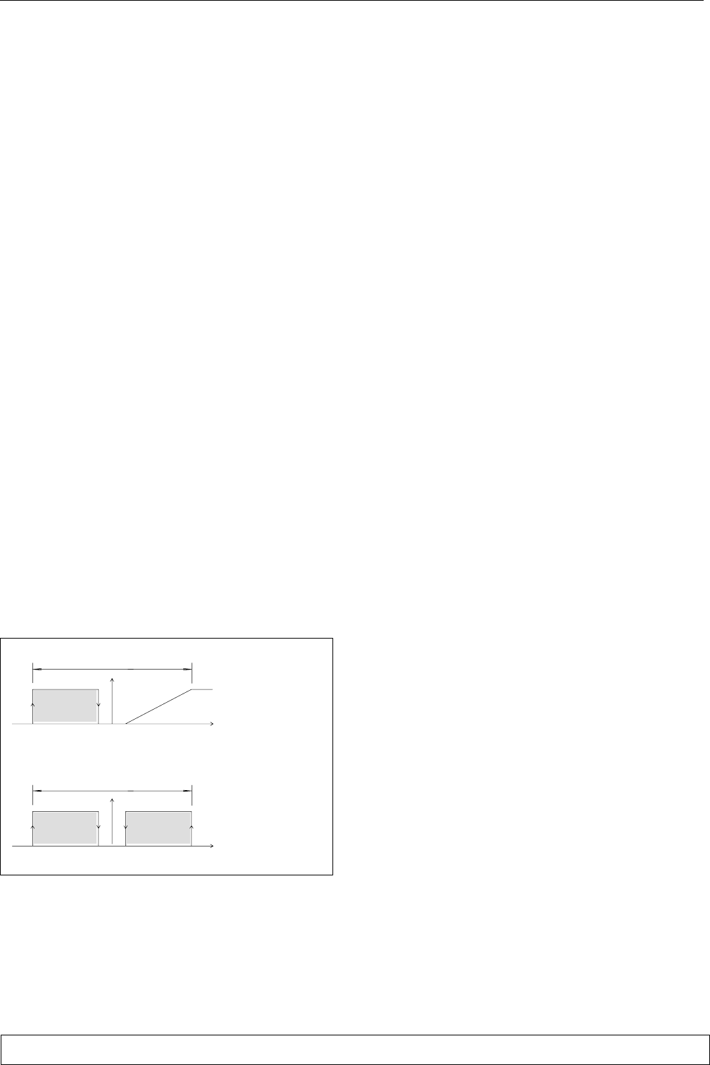
Fig. b, shown as an example, describes the operation of a
system consisting of 3 units.
Fig. b System with 2 units in stand-by -
Microface control
Set CCoolingHeating
3
Freecooling mode
1
2
3
Compressor cooling mode
11
223
P Band
P Band
Set CCoolingHeating
1 = main unit
2 = unit in stand-by
3 = unit in stand-by
7 - Refrigerant R22 and oil charge
THESE OPERATIONS MUST BE PERFORMED BY
AN EXPERIENCED REFRIGERATION TECHNI
CIAN.
7.1 - Features of the refrigerating fluid R22
At standard temperature and pressure it is a colourless gas
with low toxicity, non-flammable, and it has an allowed
exposure limit value (AEL/TLV) corresponding to 1000
ppm (average value measured on 8 hours/day). In the
event of leakage, air the room before use.
7.2 - Refrigerant charge
WHEN REPAIRING THE REFRIGERATION CIR
CUIT RECUPERATE ALL REFRIGERANT IN A CON
TAINER: DO NOT ALLOW IT TO ESCAPE.
1) Start the unit as described in par. 4.1.
2) Start the compressor manually.
3) Guarantee a constant condensation temperature
(preferably 42-45°C); if necessary, partially obstruct
the condenser coil surface or limit its ventilating
power to obtain these conditions.
4) Charge the unit with the quantity of refrigerant R22
as shown in Tab. 5 and wait until the operating condi
tions of the whole refrigeration circuit are normal.
5) Check that the overheating is 7-8°C.
Tab. 5 - Refrigerant charge
MODEL
PKS3 PKS4
Refrigerant charge (g) 1500 1700
7.3 - Oil charge
The oil to be used when topping up is SUNISO 3GS; if
SUNISO 3GS is unavailable use an oil with the same
characteristics (see Tab. 6).
NEVER MIX DIFFERENT OILS TOGETHER.
CLEAN THE PIPING COMPLETELY BEFORE
CHANGING THE TYPE OF OIL USED.
Tab. 6 - Suniso 3GS oil (standard)
approx. specific weight (at 15C)
flash point (C.O.C.)
pour point
ENGLER viscosity at 50 C
viscosity index
copper corrosion (100 C, 3 hours) ASTM D130
neutralization value
conradson carbon residue
dielectric strength
:
:
:
:
:
:
:
:
:
0.91 kg/l
170 C
-40 C
2.7 E
0
1
0.03 max.
0%
> 30 kV
page 8
English 272014 - 04.02.2000
8 - Calibrations
The air conditioner has already been factory-tested
and calibrated as described below.
For the MICROFACE calibrations refer to the rele
vant manual (to avoid wrong operations do not use
temperature and rel. humidity set points/propor
tional bands which differ excessively from the stan
dard settings).
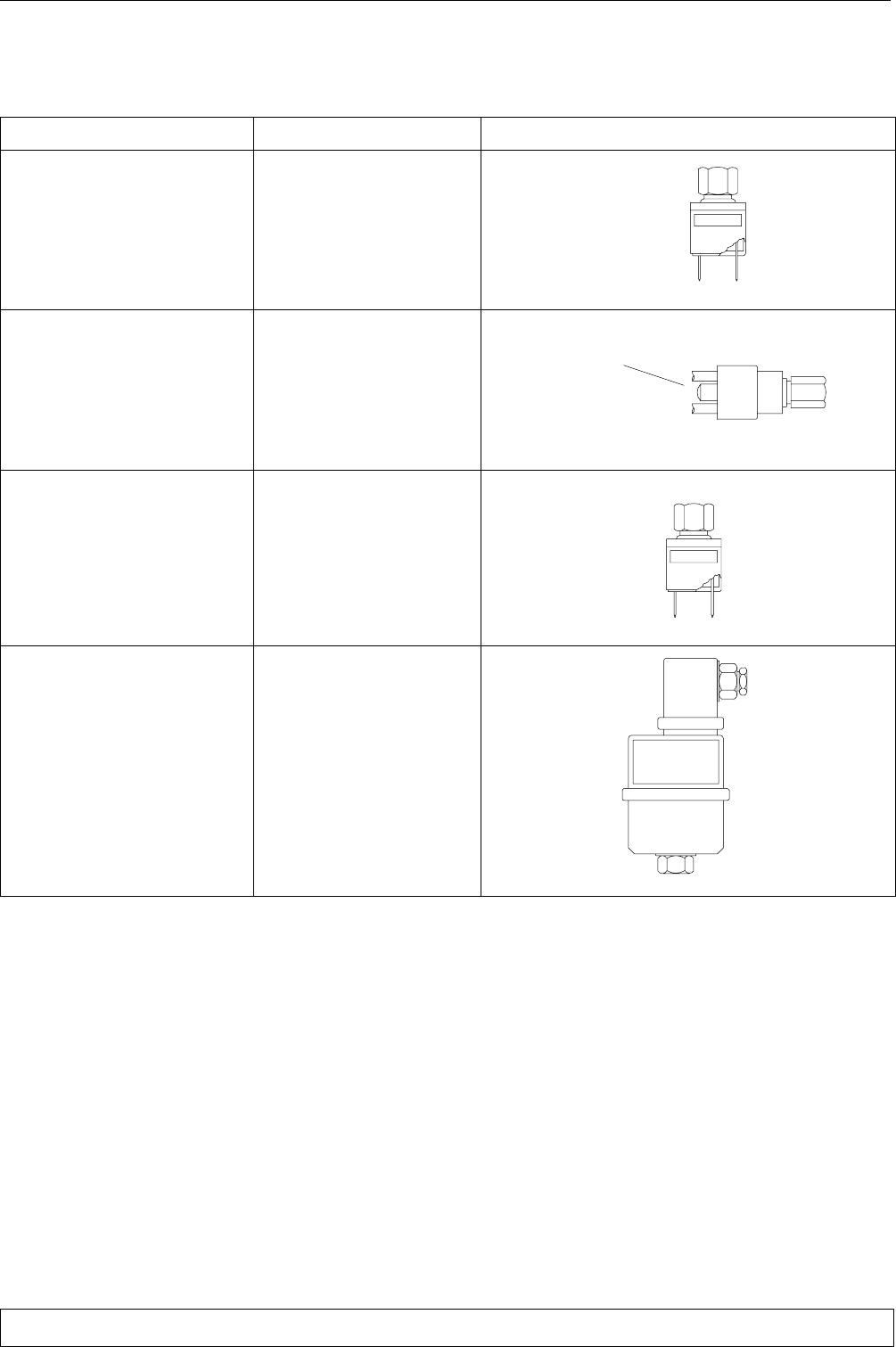
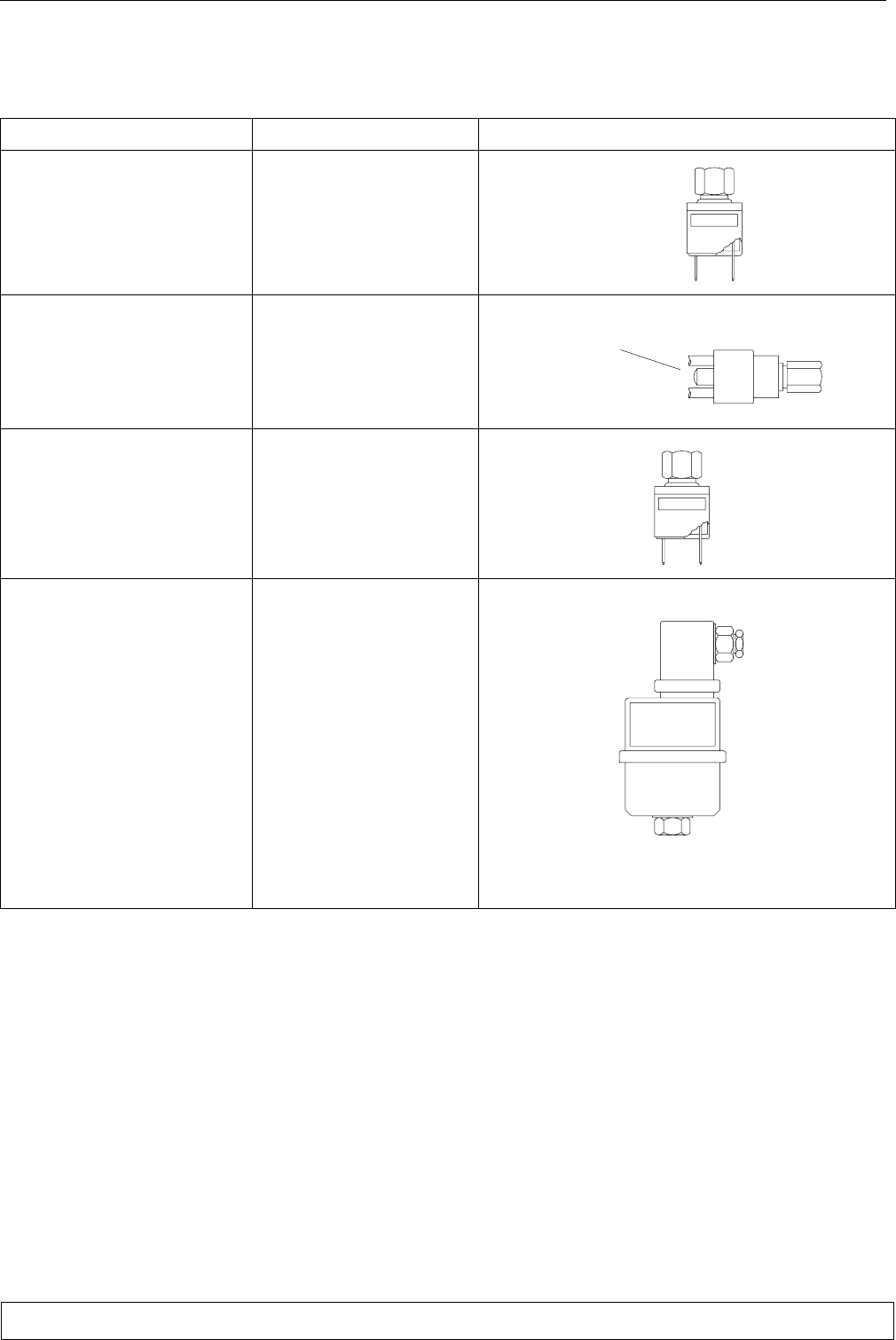
COMPONENT Setting (LP) NOTES
Low pressure
switch (LP)
STOP : 1.2 bar
START : 2 bar
(fixed settings)
automatic
reset
High pressure
switch (HP)
STOP : 26 bar
START : 20 bar
(fixed settings)
manual reset
pressing the
push button
Fan
pressure switch
(SP)
START : 18 bar
DIFF : 4 bar
(STOP : 14 bar)
(fixed settings)
Fan speed
adjuster
SET. : 16 bar
BAND P : 3.5 bar
(For the adjustment refer
to the instructions supplied
with the machine)
page 9 English
9 - Maintenance
For safety reasons, clear the unit opening the switches
QS1 and QS2 before performing any maintenance
operations.
If installed:
AS THE HIROMATIC/MICROFACE FEATURES
AUTOMATIC RESTART (AFTER A SUPPLY
INTERRUPTION) IT IS ADVISED TO DISABLE
AUTORESTART AND OPEN THE SWITCH QS
WHEN PERFORMING ANY MAINTENANCE.
Every day check the Hiromatic/Microface readings for
temperature and, if shown, ambient relative humidity.
The Maintenance Programme described below
should be carried out by a skilled technician, prefer
ably working under a maintenance contract.
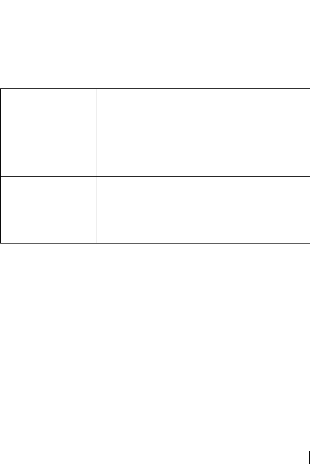
Maintenance program - Monthly check
FANS
Check that the fan motor rotates freely without any abnormal noise, and ensure
that the bearings are not running hot.
Also check the current absorption.
AIR FILTERS
Check the filter conditions; if necessary clean or replace them.
How to replace:
remove the upper panel of the unit
extract the filter from its seat horizontally
introduce the spare part
close the panel
In very dusty environments perform this check more frequently.
HIROMATIC/MICROFACE Verify the operation of the HIROMATIC/MICROFACE's LEDs, display and
alarms.
ELECTRICAL
CIRCUIT
Check the power supply on all phases.
Ensure that all electrical connections are tight.
REFRIGERATION
CIRCUIT
Check the evaporating pressures (to be done by a refrigeration technician).
Check the compressor current absorption, its head temperature and the pres
ence of any unusual noise.
Ensure that there is no ice formation on the evaporator.
9.1 - Dismantling the unit
The machine has been designed and built to ensure con
tinuous operation.
The working life of some of the main components, such
as the fan and the compressor, depends on their mainte
nance.
If the unit has to be dismantled, this must be done by
skilled refrigerator technicians.
The refrigerating fluid and the lubricating oil in the cir
cuit must be disposed of in conformity with the laws in
force in your country.
page 10
English 272014 - 04.02.2000
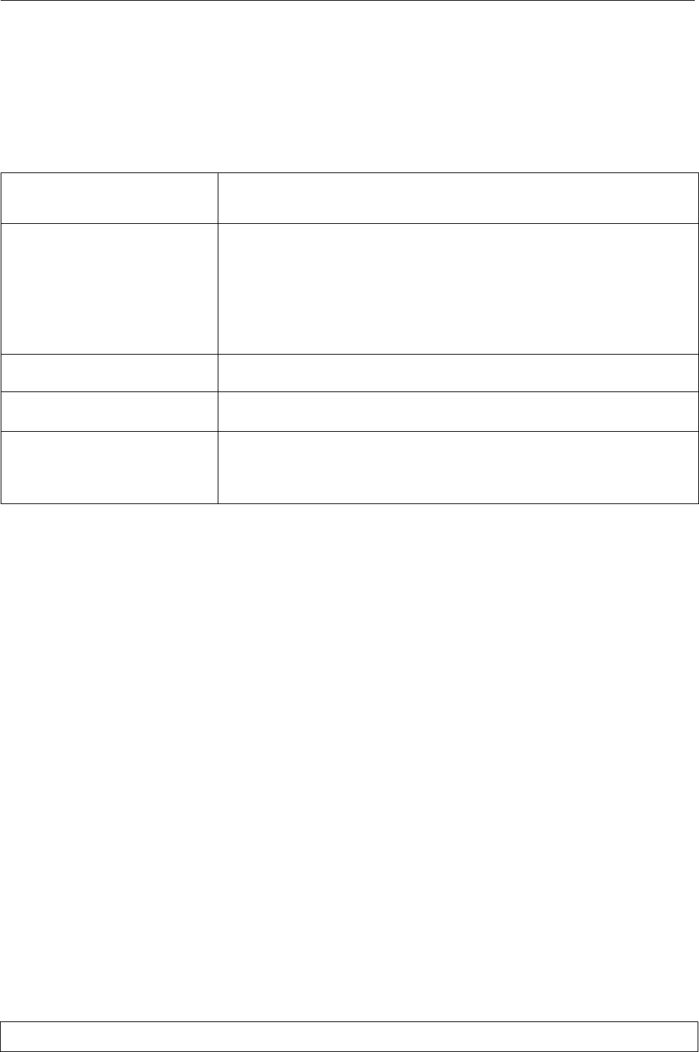
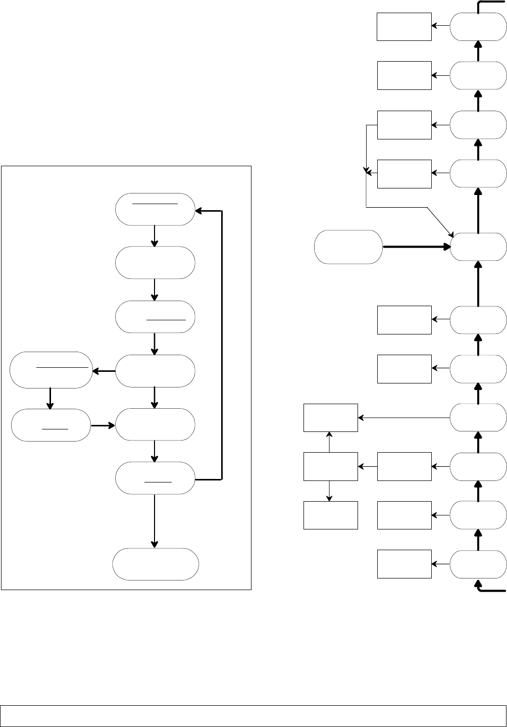
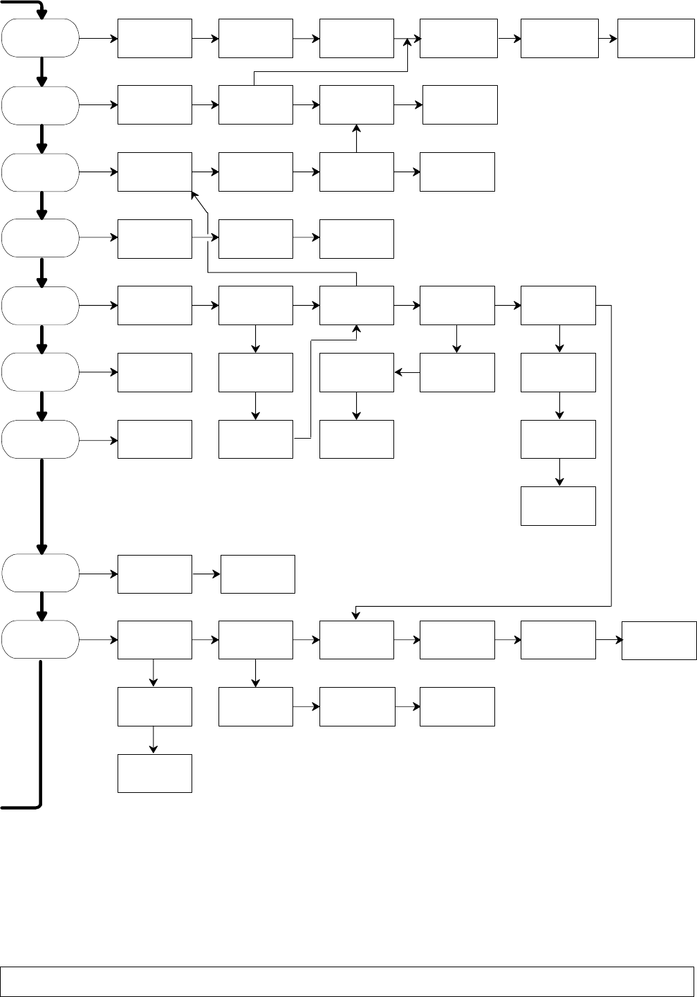
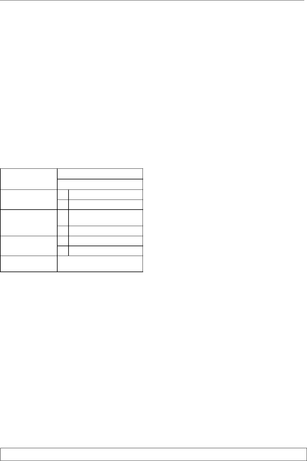
10 - Fault finding / alarms
Use the Fault Finding Guide on the right as follows:
Begin with "START" and follow the arrows marked both "YES" and
'NO' according to the type of fault.
The guide uses the following abbreviations:
Control of the HIR32 series
When an alarm occurs, the buzzer and the display indication can be reset manually pressing the
key PRG/mute. For the alarm code the reset is active only if the alarm cause has been removed.
The reset for the alarm contact is automatic. The reset of the adjuster operation occurs auto
matically when the alarm cause is removed.
For better information see the HIR32 manual.
Microface control
The alarms, shown in the guide, are reset as in
Fig. f.
Fig. c - How to reset an alarm
ALARM ON
(alarm LED
+ buzzer on)
read alarm
message
on display
press RESET
(mutes siren)
do you know
which alarm
has intervened?
rectify problem
using Fault
Finding Guide
press RESET
return to
normal operation
(alarm LED off)
fault
rectified
fault not rectified
press REPORT:
verify which alarm
has intervened
No
Yes
press HOME
check fan
operation plus
electrical circuit
check for high
air temperature
or low air flow
switch manual
operation off
reset conditioner
model
replace
interface
board
replace
EPROM
START
replace
HIROMATIC/
MICROFACE
is normal
operation
restored?
continue
normal
operation
switch unit
main switch
off and then on
replace
sensor
verify state
of component:
continue if
everything is ok
unit operating
in manual
correct condi
tioner model on
Hiromatic/
Microface
is unit
operating
correctly?
faulty
interface
card
EPROM error
display board
failure
RAM/EPROM
error
Yes
No
Yes
No
Yes
No
No
Yes
No
Yes
No
Yes
No
Yes
No
Yes
No
Yes
No
No
Yes
Yes
No
air flow
lack
electric
heater
overheating
sensor
failure alarms
working
hour
alarms
NOTES:
If several alarms intervene in sequence, only the last to inter
vene is displayed.
The STATUS REPORT lists all recent alarms (see Hiromatic/
Microface manual).
For further information see the Hiromatic manual.
page 11 English
high outside
temperature:
consult
supplier
excessive
refrigerant charge:
reduce charge
dirty
condenser:
clean
it
low outside
temperature:
check
refrigerant charge
low condensing
(temperature)
pressure
faulty
fan PV
pressure switch:
replace
leak of refrigerant:
repair leak and
recharge
locked filter
dryer:
replace it
capillary locked:
replace
reduced
air flow
clogged filters
or locked air
flow: verify
suction pipe
heats up when
compressor stops:
replace compressor
excessive
superheat
high room
temperature:
reduce temp.
leak of refrigerant:
repair leak and
recharge
locked freecooling
damper: unlock
servocontrol
fault: replace
partially
frozen
evaporator
unit is not
cooling
hot compressor
or klixon
intervention
act as
necessary
compressor not
under power:
check electrical
and control circuit
is the compressor
faulty?
act according to
local regulations faulty room
sensor: replace
faulty compr.
substitute by
expert technician
excess current
absorption:
call expert
technician
noisy compressor:
substitute by
expert techncian
unit is
cooling
unit is not
heating faulty control
circuit wiring:
check el. circuit
faulty control
function: replace reduced
air flow
unit in
dehumidification
wait for
temperature to rise
electrical
heaters are off
no power
arriving: check
electrical circuit
and safety T-stat
element burnt
out: replace
and check
electrical circuit
clogged filters
or locked air
flow: verify
faulty room
sensor: replace
partially
frozen
evaporator
compressor
overheating
Yes
No
high ambient
temperature
low ambient
temperature
No No No
Yes
No
No Yes No
No
No
Yes
No
No No Yes
Yes
No
No Yes
Yes
No
No No No No
Yes
Yes Yes Yes
Yes
No No No
Yes
No
Yes NoNoNoNo
YesYes
Yes No
No
No
Yes
No
No
leak of refrigerant:
repair leak and
recharge
too much
refrigerant:
reduce charge
cold/noisy
compressor
No
Yes No
burnt out fan
motor: replace
pressure switch/
t-stat/variex faulty
or capillary
locked: rectify
pressure switch/
t-stat/variex
miscalibrated:
recalibrate
compressor HP
alarms
compressor LP
alarms
user alarms
smoke/fire alarm
(optional)
No No
faulty external
sensor: replace
No
capillary fault:
replace
Yes

page 12
English 272014 - 04.02.2000
11 - Spare parts
It is recommended the use of original spare parts.
When placing an order refer to Component List" enclo
sed with the machine and quote the unit model no. and
serial no.

pag. 1 Italiano
Avvertenze
Si raccomanda:
di conservare il manuale per tutto il periodo di vita della macchina;
di leggere con attenzione il manuale prima di qualsiasi operazione sulla macchina;
di impiegare la macchina esclusivamente per lo scopo per cui e' stata progettata; l'uso improprio dell'unita' eso
nera il costruttore da qualsiasi responsabilita'.
Il manuale e' rivolto all'utente finale per le sole operazioni eseguibili con pannelli chiusi.
Le operazioni che necessitano dell'apertura di porte o pannelli con attrezzi devono essere eseguite solo da personale
esperto.
Ogni macchina è munita di dispositivo Di Sezionamento Elettrico che consente all'operatore di intervenire in condi
zioni di sicurezza. Tale dispositivo deve essere sempre usato per eliminare i pericoli durante la manutenzione (scosse
elettriche, scottature, ripartenza automatica, parti in movimento e controllo remoto).
La chiave data in dotazione che permette la rimozione dei pannelli deve essere conservata dal personale addetto alla
manutenzione.
Per identificare la macchina (modello e numero di serie), in caso di richiesta di assistenza o di ricambi, leggere la
targhetta di identificazione posta esternamente ed internamente all'unita'.
ATTENZIONE: questo manuale e' suscettibile di modifiche; pertanto, ai fini di una completa e aggiornata informazione, l'utente
dovra' consultare il manuale a bordo della macchina.
Indice
1 - Operazioni preliminari 2. . . . . . . . . . . . . . . . . . . . . . . . . . . . . . . . . . . . . . . . . . . . . . . . . . . . . . . . . . . . . . . . . . . . . . . . . . . . . . . . . . . . . . . .
1.1 - Premessa 2. . . . . . . . . . . . . . . . . . . . . . . . . . . . . . . . . . . . . . . . . . . . . . . . . . . . . . . . . . . . . . . . . . . . . . . . . . . . . . . . . . . . . . . . . . . . . . . . . . . .
1.2 - Limiti di funzionamento 2. . . . . . . . . . . . . . . . . . . . . . . . . . . . . . . . . . . . . . . . . . . . . . . . . . . . . . . . . . . . . . . . . . . . . . . . . . . . . . . . . . . . . . . .
1.3 - Livello di pressione sonora 2. . . . . . . . . . . . . . . . . . . . . . . . . . . . . . . . . . . . . . . . . . . . . . . . . . . . . . . . . . . . . . . . . . . . . . . . . . . . . . . . . . . . . .
1.4 - Impermeabilità dell'ambiente 2. . . . . . . . . . . . . . . . . . . . . . . . . . . . . . . . . . . . . . . . . . . . . . . . . . . . . . . . . . . . . . . . . . . . . . . . . . . . . . . . . . .
1.5 - Ispezione 2. . . . . . . . . . . . . . . . . . . . . . . . . . . . . . . . . . . . . . . . . . . . . . . . . . . . . . . . . . . . . . . . . . . . . . . . . . . . . . . . . . . . . . . . . . . . . . . . . . . .
1.6 - Trasporto 2. . . . . . . . . . . . . . . . . . . . . . . . . . . . . . . . . . . . . . . . . . . . . . . . . . . . . . . . . . . . . . . . . . . . . . . . . . . . . . . . . . . . . . . . . . . . . . . . . . . .
1.7 - Posizionamento del condizionatore 2. . . . . . . . . . . . . . . . . . . . . . . . . . . . . . . . . . . . . . . . . . . . . . . . . . . . . . . . . . . . . . . . . . . . . . . . . . . . . . .
1.8 - Area di servizio 2. . . . . . . . . . . . . . . . . . . . . . . . . . . . . . . . . . . . . . . . . . . . . . . . . . . . . . . . . . . . . . . . . . . . . . . . . . . . . . . . . . . . . . . . . . . . . . .
1.9 - Fori a parete 2. . . . . . . . . . . . . . . . . . . . . . . . . . . . . . . . . . . . . . . . . . . . . . . . . . . . . . . . . . . . . . . . . . . . . . . . . . . . . . . . . . . . . . . . . . . . . . . . .
2 - Installazione 3. . . . . . . . . . . . . . . . . . . . . . . . . . . . . . . . . . . . . . . . . . . . . . . . . . . . . . . . . . . . . . . . . . . . . . . . . . . . . . . . . . . . . . . . . . . . . . . . . . .
3 - Collegamenti elettrici e kit 4. . . . . . . . . . . . . . . . . . . . . . . . . . . . . . . . . . . . . . . . . . . . . . . . . . . . . . . . . . . . . . . . . . . . . . . . . . . . . . . . . . . . .
3.1 - Collegamenti elettrici 4. . . . . . . . . . . . . . . . . . . . . . . . . . . . . . . . . . . . . . . . . . . . . . . . . . . . . . . . . . . . . . . . . . . . . . . . . . . . . . . . . . . . . . . . .
3.2 - Kit Raffreddamento d'emergenza (optional) 4. . . . . . . . . . . . . . . . . . . . . . . . . . . . . . . . . . . . . . . . . . . . . . . . . . . . . . . . . . . . . . . . . . . . . . .
4 - Avviamento 5. . . . . . . . . . . . . . . . . . . . . . . . . . . . . . . . . . . . . . . . . . . . . . . . . . . . . . . . . . . . . . . . . . . . . . . . . . . . . . . . . . . . . . . . . . . . . . . . . . . .
4.1 - Primo avviamento (o dopo una lunga interruzione) 5. . . . . . . . . . . . . . . . . . . . . . . . . . . . . . . . . . . . . . . . . . . . . . . . . . . . . . . . . . . . . . . . . .
4.2 - Avviamento con bassa temperatura esterna 5. . . . . . . . . . . . . . . . . . . . . . . . . . . . . . . . . . . . . . . . . . . . . . . . . . . . . . . . . . . . . . . . . . . . . . . .
4.3 - Avviamento e fermata 5. . . . . . . . . . . . . . . . . . . . . . . . . . . . . . . . . . . . . . . . . . . . . . . . . . . . . . . . . . . . . . . . . . . . . . . . . . . . . . . . . . . . . . . . . .
5 - Funzionamento 5. . . . . . . . . . . . . . . . . . . . . . . . . . . . . . . . . . . . . . . . . . . . . . . . . . . . . . . . . . . . . . . . . . . . . . . . . . . . . . . . . . . . . . . . . . . . . . . .
5.1 - Regolazione della velocità del ventilatore del condensatore 6. . . . . . . . . . . . . . . . . . . . . . . . . . . . . . . . . . . . . . . . . . . . . . . . . . . . . . . . . . .
5.2 -Raffreddamento di emergenza (optional) 6. . . . . . . . . . . . . . . . . . . . . . . . . . . . . . . . . . . . . . . . . . . . . . . . . . . . . . . . . . . . . . . . . . . . . . . . . .
6 - Controlli a microprocessore 6. . . . . . . . . . . . . . . . . . . . . . . . . . . . . . . . . . . . . . . . . . . . . . . . . . . . . . . . . . . . . . . . . . . . . . . . . . . . . . . . . . .
6.1 - Logica di controllo 6. . . . . . . . . . . . . . . . . . . . . . . . . . . . . . . . . . . . . . . . . . . . . . . . . . . . . . . . . . . . . . . . . . . . . . . . . . . . . . . . . . . . . . . . . . . .
7 - Carica refrigerante R22 e olio 7. . . . . . . . . . . . . . . . . . . . . . . . . . . . . . . . . . . . . . . . . . . . . . . . . . . . . . . . . . . . . . . . . . . . . . . . . . . . . . . . .
7.1 - Caratteristiche del fluido frigorigeno R22 7. . . . . . . . . . . . . . . . . . . . . . . . . . . . . . . . . . . . . . . . . . . . . . . . . . . . . . . . . . . . . . . . . . . . . . . . . .
7.2 - Carica refrigerante 7. . . . . . . . . . . . . . . . . . . . . . . . . . . . . . . . . . . . . . . . . . . . . . . . . . . . . . . . . . . . . . . . . . . . . . . . . . . . . . . . . . . . . . . . . . . .
7.3 - Carica olio 8. . . . . . . . . . . . . . . . . . . . . . . . . . . . . . . . . . . . . . . . . . . . . . . . . . . . . . . . . . . . . . . . . . . . . . . . . . . . . . . . . . . . . . . . . . . . . . . . . . .
8 - Tarature 8. . . . . . . . . . . . . . . . . . . . . . . . . . . . . . . . . . . . . . . . . . . . . . . . . . . . . . . . . . . . . . . . . . . . . . . . . . . . . . . . . . . . . . . . . . . . . . . . . . . . . . . .
9 - Manutenzione 9. . . . . . . . . . . . . . . . . . . . . . . . . . . . . . . . . . . . . . . . . . . . . . . . . . . . . . . . . . . . . . . . . . . . . . . . . . . . . . . . . . . . . . . . . . . . . . . . . .
9.1 - Smantellamento dell'unità 9. . . . . . . . . . . . . . . . . . . . . . . . . . . . . . . . . . . . . . . . . . . . . . . . . . . . . . . . . . . . . . . . . . . . . . . . . . . . . . . . . . . . . .
10 - Ricerca guasti / allarmi 10. . . . . . . . . . . . . . . . . . . . . . . . . . . . . . . . . . . . . . . . . . . . . . . . . . . . . . . . . . . . . . . . . . . . . . . . . . . . . . . . . . . . . . . .
11 - Ricambi 12. . . . . . . . . . . . . . . . . . . . . . . . . . . . . . . . . . . . . . . . . . . . . . . . . . . . . . . . . . . . . . . . . . . . . . . . . . . . . . . . . . . . . . . . . . . . . . . . . . . . . . . .
pag. 2
Italiano
1 - Operazioni preliminari
1.1 - Premessa
Il seguente manuale descrive l'installazione, il funziona
mento e la manutenzione dei Condizionatori d'aria serie
Hiline Slim (ved. Fig. 1).
IMPORTANTE:
Consultare anche il manuale del controllo a micropro
cessore Microface e Hiromatic (se installato).
1.2 - Limiti di funzionamento
Le unità sono previste per funzionamento all'interno dei
campi di lavoro (ved. Tab. 1).
Tali limiti sono intesi per macchine nuove correttamente
installate o per le quali si sia effettuata una corretta
manutenzione.
Le clausole di garanzia non sono valide per ogni possibile
danneggiamento o malfunzionamento che puo' verifi
carsi durante od in conseguenza di operazioni al di fuori
dei valori di applicazione.
Tab. 1 - Limiti operativi
Tensione alimentazione
230 V 10%/1/50 Hz
Tensione alimentazione
24/48 30% Vdc con INVERTER
Condizioni esterne
da: -10C (-30C con VARIEX)
Condizioni esterne a: 43C
Condizioni interne con
compressore funzionante
da: 20C 30% R.H. e 20C 80%
R.H.
compressore funzionante a: 35C, 40% R.H.
Condizioni di da: -25C, 5% R.H.
Condizioni
di
immagazzinamento a: 55C, 90% R.H.
Grado di protezione lato
esterno IP 24
1.3 - Livello di pressione sonora
Nella Tab. 2 vengono riportati, per il lato interno e per il
lato esterno, i valori di pressione sonora massimi per le
unita' in configurazione standard, in funzionamento
continuo, a 2 metri dalla superficie frontale della mac
china, a 1 metro di altezza, in condizione di campo libero.
I valori di rumorosita' piu' elevati si riscontrano frontal
mente all'unita', sul lato interno.
1.4 - Impermeabilita' dell'ambiente
Per creare stabili condizioni interne assicurarsi che la
stanza sia isolata dall'esterno sigillando le aperture, le
entrate dei cavi, ecc.
1.5 - Ispezione
Al ricevimento della macchina controllare immediata
mente il suo stato; contestare subito alla compagnia di
trasporto qualsiasi eventuale danno.
1.6 - Trasporto
Tenere sempre l'unita' in posizione verticale.
Se possibile trasportare la macchina usando un car
rello elevatore a forca; altrimenti usare una gru con
cinghie o funi, evitando di esercitare pressione sugli
angoli superiori dell'imballaggio.
Disimballare l'unita' il piu' vicino possibile al luogo
dell'installazione. Una volta disimballata evitare urti
che possono essere trasmessi ai componenti interni.
1.7 - Posizionamento del condizionatore
Il condizionatore d'aria puo' essere collocato in qual
siasi ambiente purche' questo non sia aggressivo.
Il condizionatore d'aria va posizionato in modo da
assicurare la migliore distribuzione d'aria nell'am
biente in cui esso deve operare, al fine di evitare zone
morte.
Per il corretto posizionamento del condizionatore ve
dere Fig. 2 in calce al manuale, che illustra l'installa
zione di due unità.
1.8 - Area di servizio
L'unità deve essere provvista di un'Area di Servizio
adatta (ved. Fig. 2):
Tutta la manutenzione ordinaria può essere realiz
zata dalla parte frontale e dalla parte posteriore
(esterna), dove uno spazio minimo deve essere
lasciato libero da ostruzioni.
1.9 - Fori a parete
Praticare i fori nella parete del container in corrispon
denza alla posizione del condizionatore (ved. Fig. 3).

pag. 3 Italiano
Tab. 2 - Livelli pressione sonora
Modello
Frequenza di banda d'ottava (Hz) Livello di
pressione
M
o
d
e
ll
o31.5 63 125 250 500 1000 2000 4000 8000
p
sonora
[dB(A)]
PKS3
Ambiente interno, a 2 m
in fronte all'unità, campo
libero 49 56 62 58 55 54 53 53 51 61
PKS3
Ambiente esterno, a 2 m
in fronte all'unità, campo
libero 50 51 49 54 51 51 47 44 37 55
PKS4
Ambiente interno, a 2 m
in fronte all'unità, campo
libero 49 56 62 58 55 54 53 53 51 61
PKS4
Ambiente esterno, a 2 m
in fronte all'unità, campo
libero 50 51 49 54 51 51 47 44 37 55
2 - Installazione
Per una corretta installazione procedere come segue
(Fig. 4):
Applicare all'unità gli elementi della cornice di prote
zione (fornibili come kit optional), utilizzando i fori
predisposti e viti autofilettanti di diametro 3.5 mm.
Per prevenire l'ingresso di acqua nel container, appli
care come guarnizione una striscia di gomma adesiva.
Fissare la cornice alla parete dello shelter per mezzo
di viti M4 con tassello.
Applicare l'elemento inferiore della cornice di prote
zione con due viti M4 con tassello.
Applicare al tetto dell'unità la staffa di fissaggio alla
parete con due viti autofilettanti di diametro 3.5.
3 - Collegamenti elettrici e kit
Prima di eseguire qualunque operazione sulle parti elet
triche, assicurarsi che:
i componenti elettrici siano in buone condizioni;
tutte le viti terminali siano ben avvitate;
la tensione di alimentazione e la frequenza siano con
formi a quelle indicate sull'unità;
l'interruttore QS1 sia in posizione di aperto (OFF);
l'interruttore automatico QS2 sui morsetti d'uscita
dell'inverter (se installato) sia aperto (OFF);
non vi siano componenti sotto tensione.
3.1 - Collegamenti elettrici
(ved. schema elettrico)
I collegamenti elettrici (alimentazione 230/1/50 e, per
l'alimentazione d'emergenza (48 e 24 Vdc) si effettuano
dal tetto dell'unità dove sono stati predisposti alcuni fori
con pressacavi.
Far passare il cavo di alimentazione (non fornito da
noi), attraverso il foro praticato nel tetto dell'unità.
N.B.: Per l'alimentazione utilizzare un cavo scher
mato (sezione minima indicata in Tab. 4).
Si raccomanda di tenere il cavo di alimentazione dalla
rete il più lontano possibile dagli altri cavi uscenti
dall'inverter (opzionale).
Collegare la linea a 230V/1/ 50 all'interruttore QS1
posto nel quadro elettrico.
Per quanto concerne i contatti di allarme presenti
nelle varie versioni, questi sono disponibili su morset
tiera nel quadro elettrico.
Per la descrizione degli allarmi, consultare il Cap. 6 e
il manuale del controllo installato.
Per porre in comunicazione 2 o più unità installate
nello stesso container, e dotate del controllo
MICROFACE, con interfaccia HIROMATIC, utiliz
zare il cavo HIROBUS (fornito in dotazione) colle
gandolo come indicato nello schema elettrico. Con
sultare inoltre il manuale Microface e Hiromatic per
la configurazione delle unità in Stand-by.
pag. 4
Italiano
Tab. 3 - Caratteristiche elettriche standard
Ventilatori evaporatore Ventilatori condensatore Compressore Resistenze riscaldamento
OA FLA LRA Potenza nom.
[W]
OA FLA LRA Potenza nom.
[W]
OA
(*)
FLA LRA Potenza nom.
[W] (*)
OA FLA LRA Potenza nom.
[W]
PKS3 1 - - 200 1.5 - - 340 5.9 10 34 1370 - 13 - 3000
PKS4 1 - - 200 1.5 - - 340 7.1 12 36.5 1700 - 13 - 3000
(*) Nelle seguenti condizioni (ARI 520-78):
Temp. condensazione: 54.4C
Temp. ambiente: 35C
Temp. evaporazione: 7.2C
Temp. sottoraffreddamento: 8.3C
Temp. surriscaldamento: 11C
Tab. 4 - Interruttore di protezione e dimensionamento cavo
Interruttore di protezione a corrente differenziale In = 0.3A Dimensionamento cavo
V230/1/50Hz 230 Vac 24/48Vdc
PKS3-PKS4
20A
4mm
2
4mm
2
PK
S3
-PK
S4
20A
4
mm
2
4
mm
2
3.2 - Kit Raffreddamento d'emergenza
(optional)
Il Kit Raffreddamento d'emergenza è costituito da un in
verter e da un trasformatore monofase, installati all'in
terno del quadro elettrico.
Agendo come illustrato nel par. 3.1, portare l'alimenta
zione a 48 (24) Vdc all'interno del quadro elettrico, per
mezzo di un cavo schermato di sezione minima riportato
in Tab. 4. Collegare l'eventuale linea di terra al morsetto
di terra (PE). Collegare la schermatura del cavo al mor
setto giallo-verde ed eseguire i collegamenti seguendo
scrupolosamente lo schema elettrico.
N.B.: Collegare correttamente la polarità.
Per quanto riguarda le unità predisposte per ali
mentazione d'emergenza da Inverter esterno, ese
guire i collegamenti come specificato nello
schema elettrico.
4 - Avviamento
4.1 - Primo avviamento (o dopo una lunga
interruzione)
Prima di avviare il condizionatore si raccomanda nuova
mente di verificare che la tensione e la frequenza d'ali
mentazione siano conformi a quelle indicate sulla tar
ghetta identificativa dell'unità.
Fatto ciò, è possibile avviare il condizionatore portando
l'interruttore QS1 nella posizione ON. Sulle unità che ne
sono equipaggiate, premere anche il pulsante ON- OFF
sull'interfaccia Hiromatic.
Controllare l'assorbimento elettrico di tutti i componen
ti e confrontare con i dati riportati nella Tab. 3. Verifi
care che non vi siano allarmi attivi; attendere che il siste
ma si porti a regime ed effettuare i seguenti controlli:
verificare che i ventilatori stiano funzionando corret
tamente;
assicurarsi che la temperatura sia garantita e che il
compressore e le resistenze di riscaldamento (optio
nal) funzionino quando richiesto;
solo su versioni dotate di opzione Variex (regolazione di
velocità) assicurarsi che il regolatore di velocità del
ventilatore della sezione condensante sia tarato cor
rettamente e che controlli il funzionamento del venti
latore (ved. Cap. 8).
4.2 - Avviamento con bassa temperatura
esterna
In caso di bassa temperatura esterna (<0C), la partenza
dell'unità è agevolata dal tempo di ritardo di attivazione
dell'allarme di bassa pressione), entro il quale le pressio
ni nel circuito frigorifero raggiungono i valori normali di
funzionamento.
4.3 - Avviamento e fermata
Per le unità dotate di interfaccia HIROMATIC:
avviare l'unità premendo il pulsante ON-OFF
sull'Hiromatic (confermato da SYS.ON sul display);
fermare l'unità premendo il pulsante ON-OFF
sull'Hiromatic (confermato da SYS.OFF. sul display).
N.B.: Spegnere l'interruttore principale QS1 e l'inter
ruttore Inverter QS2 (o aprire i fusibili FU4) solo
se l'unità viene fermata per un lungo periodo di
tempo.
Per le unità dotate del controllo Microface, l'accensione
e lo spegnimento si ottengono agendo sull'interruttore
principale QS1, al quale si accede aprendo il pannello su
periore incernierato agendo sul sistema di apertura rapi
da.

pag. 5 Italiano
5 - Funzionamento
Il funzionamento dell'unità è completamente automati
co. La sequenza che segue spiega (con l'aiuto della Fig. 5
- Schema di funzionamento) come funziona l'unità (ve
dere anche la Fig. 6 - Circuito frigorifero):
6) Il sensore di temperatura, posizionato all'interno del
lo shelter, fornisce al controllo l'informazione relati
va alla condizione dell'aria da trattare .
7) Il controllo confronta l'informazione ricevuta con i
valori di Set Point (= temperatura interna minima
desiderata) e Differenziale programmati, predispo
nendo il condizionatore al trattamento dell'aria, con
le seguenti modalità:
Raffreddamento (Fig. 5)
Il compressore (9) e i ventilatori (6) e (10) vengono
avviati quando la temperatura dell'ambiente da condi
zionare supera il valore prefissato. L'aria aspirata dai
ventilatori assiali (6) entra nell'unità tramite l'accesso
superiore (A), attraversa immediatamente il filtro (1) e
quindi l'evaporatore (5).
Il refrigerante freddo fluisce attraverso l'evaporatore
(5), raffreddando così l'aria che l'attraversa. L'aria trat
tata viene convogliata nell'ambiente condizionato attra
verso l'apertura di mandata (B).
Il calore sottratto all'ambiente e quello generato dal fun
zionamento dei motori del condizionatore vengono
smaltiti attraverso il condensatore (11), posto nella parte
dell'unità a contatto con l'esterno e investito, grazie ai
ventilatori (10), dall'aria esterna. Il funzionamento dei
ventilatori viene gestito in modo ON - OFF (o con
Variex, ved. par. 5.1) in funzione della pressione di con
densazione.
Per la logica di funzionamento del controllo ved. Cap. 6.
Riscaldamento (optional)
Il riscaldamento dell'aria si ottiene per mezzo di resisten
ze elettriche (7), poste nel flusso d'aria e azionate secon
do la logica impostata sul controllo (ved. Cap. 6).
Il reset manuale del termostato di sicurezza (15), posto
sulle resistenze, va effettuato accedendo dalla parte
frontale, dopo aver rimosso il pannello grigliato.
Raffreddamento in Freecooling (optional) - (Fig. 5)
Quando la temperatura dell'aria esterna è inferiore alla
temperatura dell'aria interna di qualche grado, è possibi
le sfruttare questa differenza per rinfrescare l'interno
dello shelter mediante l'immissione diretta di aria ester
na, senza cioè l'uso del compressore. E' possibile ottene
re così un sensibile risparmio di energia elettrica.
Al verificarsi delle condizioni previste, il servocomando
(2), gestito dal controllo Microface, apre la serranda mo
bile (12) che separa la circolazione dei due flussi d'aria
interna ed esterna. In questo modo l'aria esterna, aspira
ta dai ventilatori (6), affluisce all'interno del container e
ne fuoriesce attraverso le aperture praticate nella se
zione condensante. I flussi d'aria presenti in questo
modo di funzionamento sono indicati nella Fig. 5.
Il grado di apertura della serranda viene determinato in
funzione del valore di Set Point da mantenere e della
temperatura dell'aria immessa (ved. Cap. 6).
5.1 - Regolazione della velocità del ventila
tore del condensatore (obbligatorio per
temp. esterne -10 / -30C)
Un sensore è posizionato in maniera tale da rilevare co
stantemente la pressione di condensazione del gas refri
gerante. In base a questa informazione, un'apparecchia
tura elettronica (Variex) regola la velocità di rotazione
del ventilatore al fine di mantenere la pressione di con
densazione entro i valori consentiti. In questo modo, ol
tre ad ottimizzare il funzionamento del compressore, si
ottiene una sensibile riduzione del livello di emissione
sonora (specialmente durante le ore notturne), si facilita
la partenza del compressore alle basse temperature e si
ottiene un risparmio di energia elettrica.
Per quanto riguarda la taratura del regolatore di velocità,
ved. il Cap. 8.
5.2 - Raffreddamento di emergenza
(optional)
Questa opzione è disponibile per tutte quelle applica
zioni in cui è importante garantire la circolazione
dell'aria all'interno dello shelter, anche quando vi è
un'interruzione dell'alimentazione elettrica dalla rete.
In questo caso, tramite un inverter e un trasformatore, le
unità possono essere alimentate con le batterie d'emer
genza a 24 oppure a 48 Vdc (ved. Fig. 7).
La modalità di intervento del sistema di emergenza
dipende dallo stato dell'interruttore QS1:
QS1 = ON
Se non ci sono interruzioni sull'alimentazione princi
pale il sistema di emergenza resta inattivo;
se viene a mancare tensione sulla linea di alimenta
zione principale, automaticamente l'inverter si attiva
e, prelevando energia dalle batteria d'emergenza a
24/48 Vdc, tramite il trasformatore 24/48 V / 230 V
alimenta il ventilatore della sezione evaporante e il
controllo elettronico. In questo modo tutte le funzio
ni dell'unità continuano ad essere gestite, consenten
do il ricircolo dell'aria interna (o l'afflusso di aria es
terna, se l'unità è dotata del sistema Freecooling) nel
caso in cui la temperatura all'interno dello shelter
esca dal range consentito. In questa modalità di fun
zionamento un contatto del relè (KM6) segnala l'atti
vazione del sistema inverter.
Se il voltaggio delle batterie d'emergenza scende al di
sotto del valore di sicurezza, il sistema inverter si
disattiva automaticamente.
QS1 = OFF
In questa condizione anomala, che si presenta ad
esempio dopo un corto circuito nell'unità, l'inverter
è automaticamente disattivato.
ATTENZIONE:
Per ragioni di sicurezza si raccomanda di disconnettere
l'interruttore automatico QS2 quando si desidera fer
mare l'unità.
pag. 6
Italiano
6 - Controlli a microprocessore
La macchina è disponibile in quatttro diverse configura
zioni di funzionamento:
1) unità solo freddo;
2) unità freddo e caldo;
3) unità con freecooling, solo freddo;
4) unità con freecooling, freddo e caldo.
Tutte le versioni sono dotate del nuovo controllo a micro
processore Microface.
6.1 - Logica di controllo
Le unità sono gestite dal controllo a microprocessore Mi
croface, eventualmente abbinato al controllo Hiromatic
per il monitoraggio completo di tutti i parametri di fun
zionamento dell'unità (ved. manuale allegato).
L'algoritmo di controllo si basa su una regolazione a 1
gradino per il riscaldamento e il raffreddamento con
compressore e su una regolazione di tipo Proporzionale
- Integrativo per il raffreddamento in modalità Free
cooling, con impostazione del Set Point e della banda
proporzionale (P) (Fig. d.)
Il controllo gestisce tutti i ritardi di attivazione del com
pressore, e i tempi minimi, al fine di garantirne il corretto
funzionamento e allungarne il più possibile la vita opera
tiva.
L'attivazione della modalità Freecooling avviene in fun
zione della differenza (impostabile) fra la temperatura
interna e quella esterna. Ciò significa che se la differenza
fra le 2 temperature aumenta oltre un certo valore, auto
maticamente l'unità passa alla funzione Freecooling: il
compressore viene disattivato e l'uscita analogica con
trolla il servomotore a 3 punti della serranda. Il grado di
apertura della serranda viene variato al fine di mantene
re la temperatura interna uguale al setpoint impostato e
in funzione della temperatura dell'aria immessa in
ambiente, che non può essere inferiore ad un prefissato
valore di sicurezza.
Fig. d Funzionamento compressore, resistenze e aper
tura serranda
Set CoolingHeating
C
P Band
C
Freecooling
mode
Compressor
cooling mode
P Band
Set CoolingHeating
Se la temperatura interna eccede la banda proporziona
le per oltre il 20% per più di 10 minuti, l'unità passa al
raffreddamento con compressore e la modalità Freecoo
ling è disabilitata per 1/2 ora. Se la temperatura interna
eccede la banda proporzionale per oltre il 50% per più di
2 minuti, la modalità Freecooling viene disattivata per 1/2
ora e si passa al raffreddamento mediante il compressore
frigorifero.
6.1.1 - Start-Stop
In totale ci sono 3 modi per avviare o arrestare l'unità:
a) l'interruttore sezionatore all'interno del quadro elet
trico;
b) l'ingresso digitale della scheda Microface;
c) il pulsante ON-OFF sull'interfaccia Hiromatic (op
zionale).
Priorità: a) b) c) devono essere considerati come 3 con
tatti in serie; solo se tutti i contatti sono in On, l'unità può
operare.
6.1.2 - Gestione allarmi
Nella configurazione standard sono disponibili sulla
morsettiera del quadro elettrico 2 contatti puliti in scam
bio, così utilizzati:
1) Allarme generale:
bassa pressione compressore
alta pressione compressore (reset sul pressostato)
guasto sensore
guasto memoria
guasto ventilatore (con sonde opzionali)
2) Avviso generale - segnalazione di varie condizioni
anomale, fra cui:
alta temperatura
bassa temperatura
termostato resistenza (reset sul termostato)
Note:
Sia l'Allarme che l'Avviso devono essere resettati
manualmente sulla Microface.
Un allarme ferma l'unità e fa intervenire quella in
stand-by (se presente). Se l'unità è in stand alone, gli
allarmi di alta e di bassa pressione non fermano la
macchina per permettere il funzionamento in moda
lità Freecooling quando le condizioni esterne lo con
sentono.
L'avviso non ferma l'unità.
In caso di intervento del termostato di sicurezza resi
stenze, il reset deve essere effettuato sul termostato
(15) accessibile rimuovendo il pannello ventilatori la
to interno.
6.1.3 - Scheda allarmi opzionale
Oltre a quanto visto per la configurazione standard, sulla
scheda allarmi fornibile come optional sono presenti
contatti di relè per avere i seguenti allarmi separati:
1) Alta pressione e bassa pressione compressore
2) Allarme filtro sporco
3) Guasto ventilatore
4) Alta temperatura
5) Bassa temperatura
Questi allarmi provocano la fermata dell'unità con le
stesse modalità viste nel paragrafo precedente.
Per la completa descrizione degli allarmi ved. manuale
Microface allegato.
pag. 7 Italiano
6.1.4 - Unità in stand-by
La gestione delle unità in stand-by è completamente
automatica grazie alla possibilità di connessione del con
trollo Microface.
Un'unità in stand-by parte in caso di un allarme che
blocca quella principale; questo avviene anche se l'unità
principale viene spenta o scompare dal sistema per un
guasto sul bus di collegamento dei controlli.
La rotazione oraria delle unità in stand-by avviene au
tomaticamente ogni 24 ore, in modo da consentire un'o
mogenea usura dei componenti del sistema.
Se il sistema è connesso all'interfaccia Hiromatic, è pos
sibile impostare una diversa gestione della rotazione.
Se più unità sono contemporaneamente in funzione con
lo stesso Set Point, la temperatura usata per il controllo è
la media di quelle rilevate; inoltre, nel funzionamento
con compressore, la banda proporzionale è divisa in
tante parti pari al doppio del numero di unità che fanno
parte del sistema, in modo da parzializzare la potenza
frigorifera totale disponibile.
Il funzionamento in modalità Freecooling è omogeneo e
contemporaneo su tutte le unità.
La Fig. e, riportata come esempio, rappresenta il funzio
namento di un sistema composto da 3 unità.
Fig. e Sistema con 2 unità in stand-by -
Controllo Microface
1 = unità principale
2 = unità in stand-by
3 = unità in stand-by
Set CCoolingHeating
3
Freecooling mode
1
2
3
Compressor cooling mode
11
223
P Band
P Band
Set CCoolingHeating
7 - Carica refrigerante R22 e olio
QUESTE OPERAZIONI DEVONO ESSERE ESE
GUITE DA UN FRIGORISTA ESPERTO.
7.1 - Caratteristiche del fluido frigorigeno R22
A temperatura e pressione normale è un gas incolore che
presenta una bassa tossicità, non è infiammabile, ha un
valore limite di esposizione permesso (AEL/TLV) pari a
1000 ppm (valore medio ponderato su 8 ore giorno).
In caso di fuga aerare il locale prima di soggiornarvi.
7.2 - Carica refrigerante
QUANDO SI RIPARA IL CIRCUITO FRIGORIFERO
RECUPERARE TUTTO IL REFRIGERANTE IN UN
CONTENITORE: NON DISPERDERLO NELL'AM
BIENTE.
1) Avviare l'unita' come descritto in par. 4.1.
2) Avviare manualmente il compressore.
3) Garantire una temperatura di condensazione
costante (preferibilmente 42-45C); se necessario
ostruire parzialmente la superficie di scambio del
condensatore o limitare la potenza ventilante per
ottenere queste condizioni.
4) Caricare l'unita' con la quantità di refrigerante R22
riportata in Tab. 5 e attendere che le condizioni di
funzionamento dell'intero circuito frigorifero risul
tino normali.
5) Verificare che il surriscaldamento sia di 3-5 °C.
Tab. 5 - Carica refrigerante
MODELLO
PKS3 PKS4
Carica refrigerante (g) 1500 1700
7.3 - Carica olio
L'olio da usare per il rabbocco e' il SUNISO 3GS; se non
e' disponibile SUNISO 3GS usare un olio con le stesse
caratteristiche (ved. Tab. 6).
NON MISCELARE MAI OLII INCOMPATIBILI.
DRENARE E PULIRE LA TUBAZIONE PRIMA DI
CAMBIARE IL TIPO DI OLIO USATO.
Tab. 6 - Olio Suniso 3GS (standard)
peso specifico approssimativo (a 15 C)
punto di infiammabilita' (C.O.C.)
punto di versamento
viscosita' ENGLER a 50 C
indice di viscosita'
corrosione su rame (100 C, 3 ore) ASTM D130
valore di neutralizzazione
residuo carbonico conradson
rigidita' dielettrica
:
:
:
:
:
:
:
:
:
0.91 kg/l
170 C
-40 C
2.7 E
0
1
0.03 max.
0%
> 30kV
pag. 8
Italiano
8 - Tarature
Il condizionatore d'aria e' gia' stato collaudato e
tarato in fabbrica come sotto riportato.
Per le tarature della MICROFACE riferirsi al rispet
tivo manuale (per evitare operazioni sbagliate non
usare set points di temperatura e umidita' rel./bande
proporzionali molto differenti dai Settaggi Stan
dard).
COMPONENTE TARATURA NOTE
Pressostato di bassa
pressione (LP)
STOP : 1, 2 bar
START : 2 bar
(tarature fisse)
reset
automatico
Pressostato di alta
pressione (HP)
STOP : 26 bar
START : 20 bar
(tarature fisse)
reset manuale
premendo il
pulsante
Pressostato
ventilatore
(SP)
START : 18 bar
DIFF : 4 bar
(STOP : 14 bar)
(tarature fisse)
Regolatore di velocità
ventilatore
SET. : 16 bar
BANDA P : 3.5 bar
(Per la regolazione vedere
istruzioni allegate a bordo
macchina)
pag. 9 Italiano
9 - Manutenzione
Per ragioni di sicurezza, togliere tensione all'unità
aprendo gli interruttori QS1 e QS2 prima di effettuare
qualsiasi manutenzione.
Se installato:
POICHE' L'HIROMATIC/MICROFACE DISPONE
DI RIPARTENZA AUTOMATICA (DOPO INTER
RUZIONE DELL'ALIMENTAZIONE) SI CONSI
GLIA DI DISABILITARE LA RIPARTENZA AUTO
MATICA E APRIRE L'INTERRUTTORE QS1 E QS2
QUANDO SI COMPIE QUALSIASI MANUTEN
ZIONE.
Controllare quotidianamente sull'Hiromatic/Micro
face la temperatura e, se indicata, l'umidita' relativa
ambiente.
Il Programma di Manutenzione che segue dovrebbe
essere eseguito da un tecnico specializzato, che opera
preferibilmente con un contratto di manutenzione.
Programma di manutenzione - Controllo mensile
VENTILATORI
Controllare che il motore del ventilatore ruoti liberamente e senza rumori ano
mali, e assicurarsi che i cuscinetti non si riscaldino.
Controllare anche l'assorbimento di corrente.
FILTRI ARIA
Verificare lo stato dei filtri; se necessario pulirli o sostituirli.
Per la sostituzione:
rimuovere il pannello superiore dell'unità (filtro interno) o la griglia superiore
esterna (filtro freecooling)
sfilare orizzontalmente il filtro dalla propria sede
inserire il ricambio
richiudere il pannello e la griglia
In ambienti molto polverosi fare questo controllo piu' frequentemente.
HIROMATIC/MICROFACE Verificare il funzionamento dei LEDs dell'HIROMATIC, del display e degli
alllarmi.
CIRCUITO
ELETTRICO
Controllare l'alimentazione elettrica su tutte le fasi.
Assicurarsi che le connessioni elettriche siano strette.
CIRCUITO
FRIGORIFERO
Controllare le pressioni di evaporazione (a cura di un frigorista esperto).
Controllare l'assorbimento di corrente del compressore, la temperatura di
testa e la presenza di eventuali rumori insoliti.
Assicurarsi che non ci sia formazione di ghiaccio sull'evaporatore.
9.1 - Smantellamento dell'unità
La macchina è stata progettata e costruita per garantire
un funzionamento continuativo.
La durata di alcuni componenti principali, quali il venti
latore e il compressore, dipende dalla manutenzione a
cui sono stati sottoposti.
In caso di smantellamento dell'unità, l'operazione dovrà
essere eseguita da personale frigorista specializzato.
Il fluido frigorigeno e l'olio lubrificante contenuto nel
circuito dovranno essere recuperati, in accordo con le
norme vigenti nel vostro Paese.
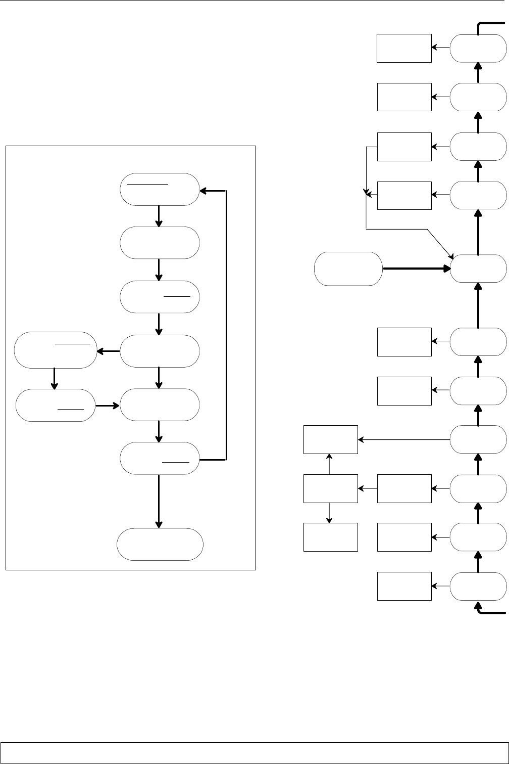
pag. 10
Italiano
10 - Ricerca guasti/ allarmi
Usare la Guida Ricerca Guasti sulla destra come segue:
Cominciare da "START" e seguire le frecce marcate sia con 'SI' che con
'NO' secondo il tipo di guasto.
La guida usa le seguenti abbreviazioni:
Controllo Microface
Gli allarmi, evidenziati nella Guida, vengono resettati come da
Fig. f.
Fig. f - Come resettare un allarme
ALLARME acceso
(LED allarme
+ cicalina accesi)
leggere
messaggio allarme
su display
premere RESET
(tacitazione cicalina)
sapete quale
allarme e'
intervenuto?
risolvere il guasto
usando la Guida
Ricerca Guasti
premere RESET
si ritorna al funzio-
namento normale
(LED all. spento)
problema
risolto
problema non risolto
premere REPORT:
verificare che allar-
me e' intervenuto
No
Si
premere HOME
controllare
funzionamento
ventilatore e
circuito elettrico
controllare sia
alta temperatura
aria che bassa
portata aria
disinserire
funzionamento
manuale
resettare
modello
condizionatore
sostituire
scheda
interfaccia
sostituire
EPROM
START
sostituire
HIROMATIC/
MICROFACE
e` ripristinato
funzionamento
normale?
continuare
funzionamento
normale
spegnere e
riaccendere
interruttore
principale
sostituire
sensore
verificare funziona
mento componenti:
continuare se
tutto OK
unita` sta
funzionando
in manuale
esatto modello
condizionatore
su Hiromatic/
Microface
sta funzionando
correttamente
l'unita?
scheda
interfaccia
guasta
errore EPROM
scheda
display guasta
errore
RAM/EPROM
Si
No
Si
No
Si
No
No
Si
No
Si
No
Si
No
Si
No
Si
No
Si
No
No
Si
Si
No
mancanza
portata aria
resistenze
elettriche
surriscaldate
allarmi
sensore guasto
allarmi
ore
funzionamento
NOTE:
Se intervengono piu' allarmi in sequenza, il display visualizza
solo l'ultimo intervenuto.
Lo STATUS REPORT elenca tutti gli allarmi recenti (ved.
manuale Hiromatic/Microface).
Per informazioni piu' dettagliate ved. manuale Hiromatic.
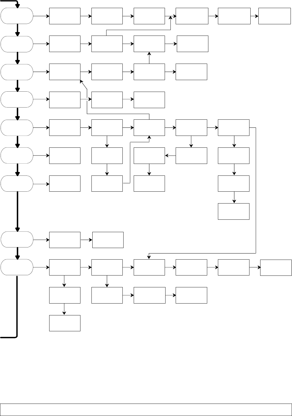
pag. 11 Italiano
alta temperatura
esterna:
consultare
fornitore
eccessiva
carica refrigerante:
ridurre carica
condensatore
sporco:
pulire
condensatore
bassa temperatura
esterna:
verificare
carica refrigerante
bassa pressione
(temperatura)
condensazione
pressostato PV
del ventilatore
difettoso:
sostituire
perdita
refrigerante:
riparare fuga
e ricaricare
filtro deidratore
bloccato:
sostituirlo
capillare bloccato:
sostituire
portata aria
ridotta
filtri sporchi
o flusso aria
bloccato:
verificare
tubo aspirazione
surriscalda a
fermata compress.:
sost. compressore
eccessivo
surriscaldamento
temperatua
ambiente alta:
ridurre
temperatura
perdita
refrigerante:
riparare
fuga e ricaricare
serranda freecooling
bloccata: sbloccare
servocomando
guasto: sostituire
evaporatore
parzialmente
ghiacciato
l'unita'
non sta
raffreddando
compressore e'
caldo o klixon
intervenuto
agire come
necessario
compressore non
alimentato:
verificare circuito
elettrico/controllo
il compressore
e' difettoso?
agire secondo
regolazioni
locali
sensore ambiente
difettoso: sostituire
compressore
guasto: far
sostituire da
tecnico esperto
assorbimento
corrente eccessivo:
chiamare tecnico
esperto
compressore
rumoroso:
sostituire da
tecnico esperto
l'unita' sta
raffreddando
l'unita'
non sta
riscaldando
guasto cablaggio
circuito controllo:
verificare circuito
funzionamento
sbagliato:
sostituire controllo
portata aria
ridotta
unita' in
deumidificazione:
attendere aumento
temperatura
resistenze
elettriche
disinserite
non arriva tensione:
controllare circuito
elettrico e termo-
stato sicurezza
resistenza
bruciata: sosti-
tuire e verificare
circuito elettrico
filtri sporchi
o flusso aria
bloccato:
verificare
sensore ambiente
difettoso: sostituire
evaporatore
parzialmente
ghiacciato
compressore
surriscaldato
Si
No
alta temperatura
ambiente
bassa temperatura
ambiente
No No No
Si
No
No Si No
No
No
Si
No
No No Si
Si
No
No Si
Si
No
No No No No
Si
Si Si Si
Si
No No No
Si
No
Si No No No No
SiSi
Si No
No
No
Si
No
No
perdita
refrigerante:
riparare fuga
e ricaricare
eccessiva carica
refrigerante:
ridurre la carica
compressore
freddo o
rumoroso
No
Si No
motore ventilatore
bruciato: sosti
tuirlo
pressostato/
termostato/variex
guasto o capillare
blocc.: ripristinare
pressostato/termo-
stato/ variex
mal tarato: ritarare
allarmi
compressore HP
allarmi
compressore LP
allarmi utente
allarme fumo/
fuoco
No No
sensore esterno
guasto: sostituire
No
capillare guasto:
sostituire
Si

pag. 12
Italiano
11 - Ricambi
Si consiglia l'uso di parti di ricambio originali.
In caso di richiesta riferirsi alla Component List" alle
gata alla macchina e specificare il modello e il numero di
serie dell'unità.
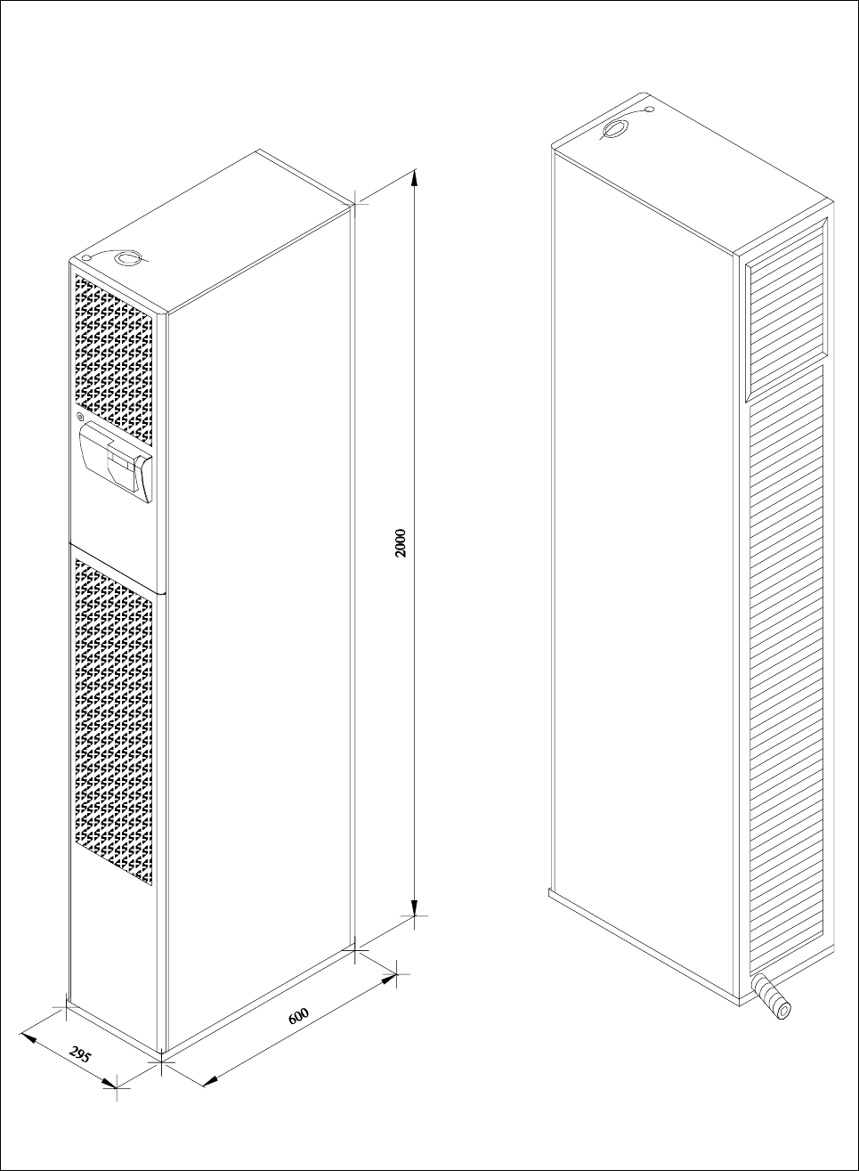
13pag.
Fig. 1 - Overall dimensions / Dimensioni di ingombro
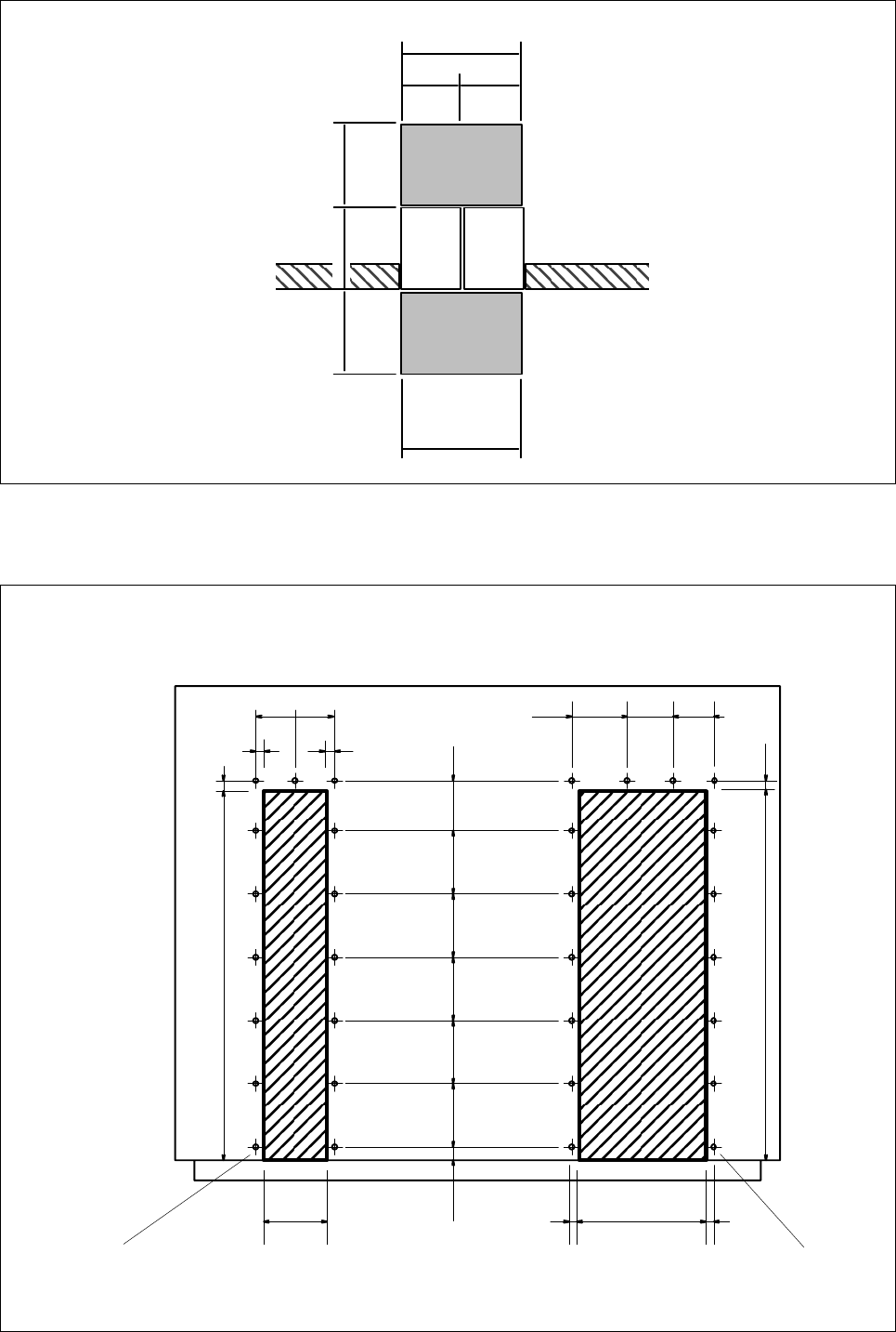
14pag.
Fig. 2 - Example of 2 unit positioning - service areas /
Esempio di posizionamento di due unità - aree di rispetto
600
300300
600
#1 #2
600 10001000
Fig. 3 - Wall holes / Forature alla parete
33.5
33.5
392
325
35
2013.5
234391391225.525
196
352013.5
196
nr. 15 holes for screws M4 with anchor
nr. 15 fori per viti M4 con tassello
single-unit installation
installazione di unità singola
double-unit installation
installazione di una doppia unità
nr. 16 holes for screws M4 with anchor
nr. 16 fori per viti M4 con tassello
33.5
33.5 624
299
391 391
= =
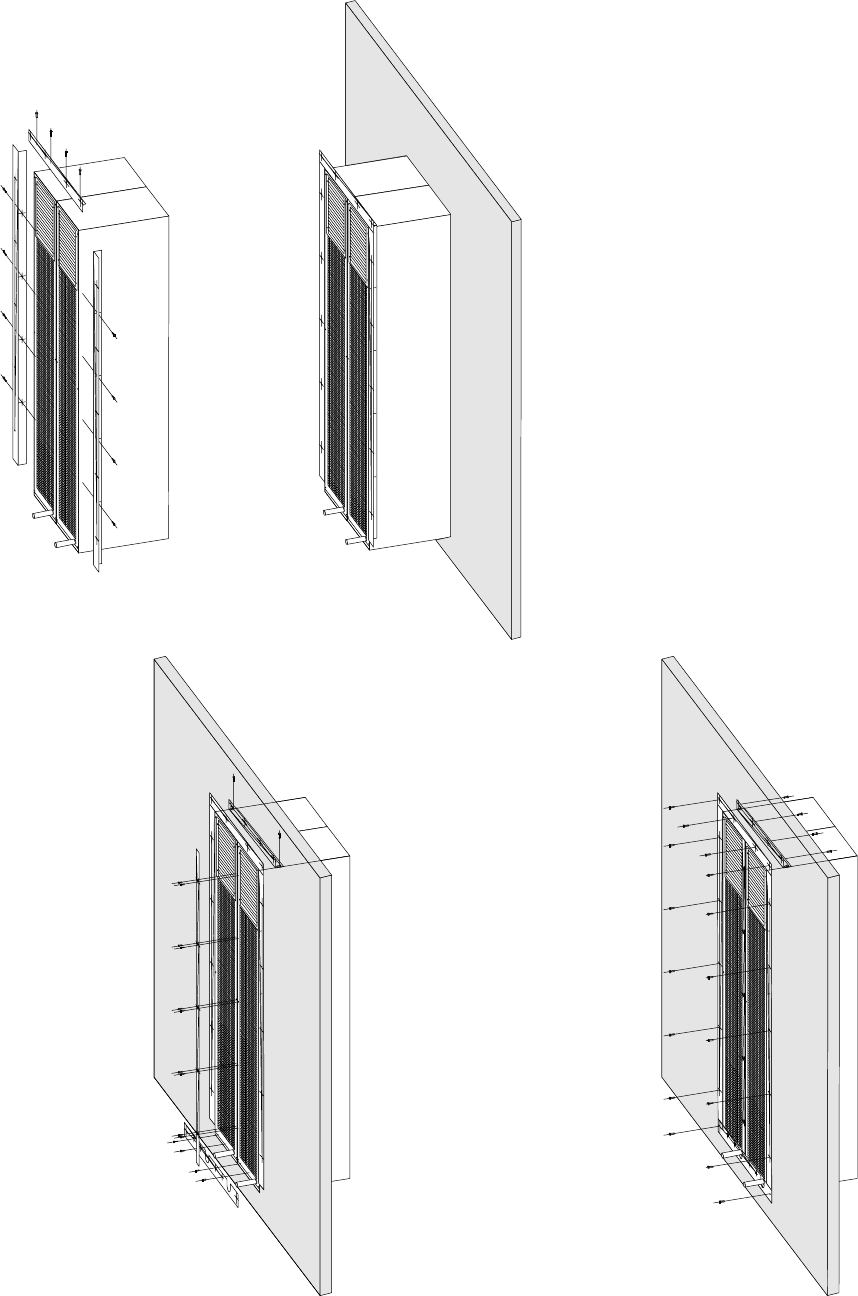
15pag.
Fig. 4 - Installation of 2 units (1 unit) / Installazione di 2 unità (1 unità)
12(11)xM4
14(2)xM4
20(18)
2xM4
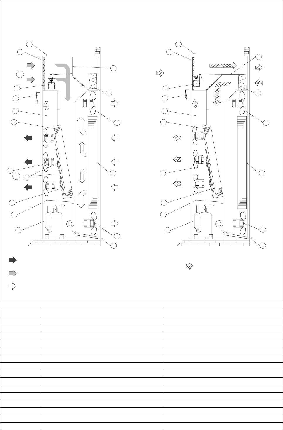
16pag.
Fig. 5 - Operation diagram / Schema di funzionamento
1 1
12
1
2
3
4
5
6
7
8
910
10
11
510
12
11
10
9
8
7
6
4
3
1
2
14 14
13 13
INSIDE
INTERNO
OUTSIDE
ESTERNO
INSIDE
INTERNO
FREECOOLING AIR –
ARIA FREECOOLING
AIR TO BE COOLED – ARIA DA TRATTARE
COOLED AIR – RIA TRATTATA
FREECOOLING – ECONOMIC COOLING
FREECOOLING – RAFFREDDAMENTO ECONOMICO
AIR CONDITIONING
CONDIZIONAMENTO
CONDENSER SECTION AIR – ARIA SEZIONE CONDENSANTE
15
A
B
POS. DESCRIPTION DESCRIZIONE
1Air filter Filtro aria
2Damper motor Motore serranda
3Electronic control Controllo elettronico
4Electrical panel Quadro elettrico
5 Evaporator Evaporatore
6Evaporator fans Ventilatori evaporatore
7Electric heaters (optional) Resistenze elettriche (optional)
8Condensate drain tank Vaschetta raccogli condensa
9 Compressor Compressore
10 Condenser fan Ventilatore condensatore
11 Condenser Condensatore
12 Freecooling damper Serranda Freecooling
13 Condensate drain Scarico condensa
14 Supply inlet cables Ingresso cavi alimentazione
15 Heating safety thermostat Termostato di sicurezza resistenze
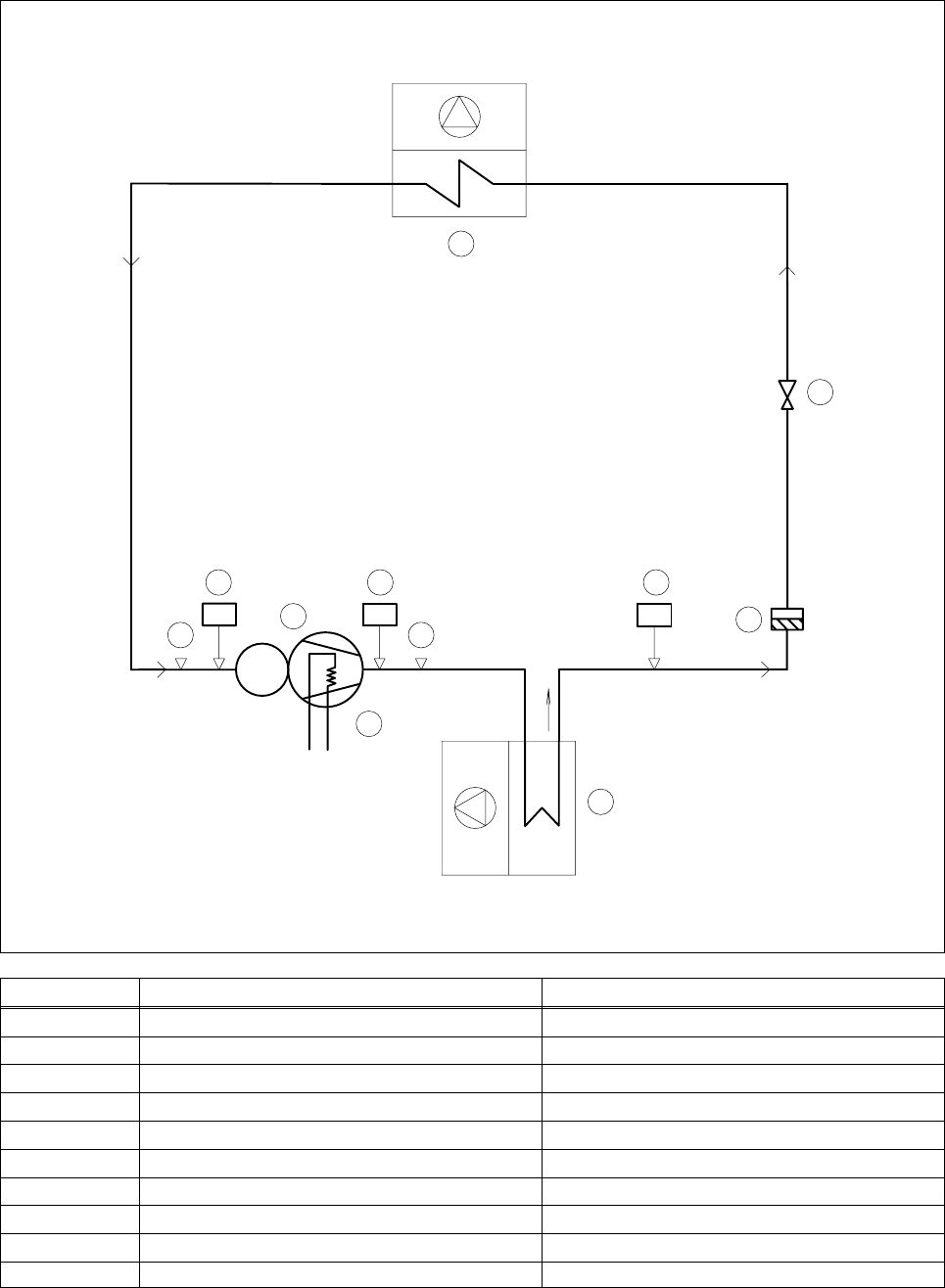
17pag.
Fig. 6 - Refrigeration circuit / Schema frigorifero
MC
7
6
5
9
44
1
28
3
10
POS. DESCRIPTION DESCRIZIONE
1 Compressor Compressore
2High pressure switch Pressostato alta pressione
3Air cooled condenser Condensatore ad aria
4Access valve Presa pressione
5Dryer filter Filtro deidratore
6Expansion capillary Capillare d'espansione
7 Evaporator Evaporatore
8Low pressure switch Pressostato bassa pressione
9Condenser pressure switch Pressostato condensatore
10 Crankcase heating element Resistenza carter

18pag.
Fig. 7 - Emergency cooling wiring diagram
Schema di principio Kit Raffreddamento di emergenza
(*) Optional, only on request
Optional, solo su richiesta
EV1
PEPE
F6 F7
INVERTER TM
48Vdc (not supplied by us)
F3
F4
PE
230 Vac
230 Vac
QS1
LF1
(3A)
CTR
TC
MD
24 Vac
CTR
(*)
QS2
KM6
KM6
KM6
POS. DESCRIPTION DESCRIZIONE
QS1 Mains supply automatic switch Interruttore automatico linea principale
TM Transformer 48/230 Vac or 24/230 Vac Trasformatore 48/230 Vac o 24/230 Vac
TC Transformer 230/24 Vac Trasformatore 230/24 Vac
CTR Electronic control (Microface) Controllo elettronico (Microface)
MD Damper motor Motore serranda / Damper motor
EV1 Evaporator fan Ventilatore evaporatore
KM6 Inverter contactor Contattore inverter
QS2 230 Vac line automatic switch Interruttore automatico linea 230 Vac
LF1 Line filter Filtro linea

Liebert HIROSS S.p.A.
Zona Industriale Tognana
Via Leonardo da Vinci, 8
35028 Piove di Sacco (PD)
ITALY
TEL. +39.049.97.19.111
FAX +39.049.58.41.257
Internet: www.Liebert-HIROSS.com
