Lifestyler 831159422 User Manual SYSTEM 300 Manuals And Guides L0904590
LIFESTYLER Weight System Manual L0904590 LIFESTYLER Weight System Owner's Manual, LIFESTYLER Weight System installation guides
User Manual: Lifestyler 831159422 831159422 LIFESTYLER LIFESTYLER SYSTEM 300 - Manuals and Guides View the owners manual for your LIFESTYLER LIFESTYLER SYSTEM 300 #831159422. Home:Fitness Equipment Parts:Lifestyler Parts:Lifestyler LIFESTYLER SYSTEM 300 Manual
Open the PDF directly: View PDF ![]() .
.
Page Count: 32
®
SYSTEM _ _ _TM
S£ARS o
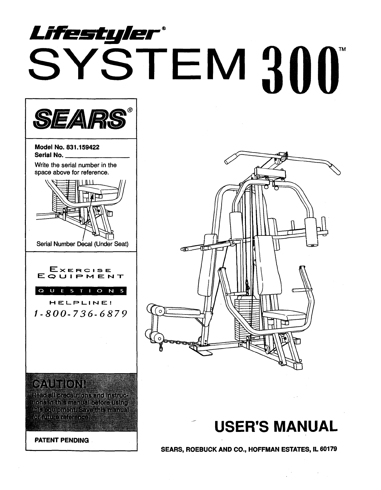
Model No. 831.159422
Serial No.
Write the serial number in the
space above for reference.
Serial Number Decal (Under Seat)
F_x EE R C I S E£:
E(_ uiPM ENT
HELPLINEI
/-800-736-6879
PATENT PENDING
USER'S MANUAL
SEARS, ROEBUCK AND CO., HOFFMAN ESTATES, IL 60179
TABLE OF CONTENTS
IMPORTANT PRECAUTIONS .............................................................. 2
BEFORE YOU BEGIN ................................................................... 3
ASSEMBLY ........................................................................... 4
HOW TO USE THE SYSTEM 300 .......................................................... 18
WEIGHT RESISTANCE CHART ........................................................... 20
TROUBLE-SHOOTING AND MAINTENANCE ................................................. 21
CABLE DIAGRAMS .................................................................... 22
ORDERING REPLACEMENT PARTS ............................................... Back Cover
LIMITED WARRANTY ........................................................... Back Cover
Note: A PART IDENTIFICATION CHART and an EXPLODED DRAWING have been attached to the center of
this manual. Remove them before beginning assembly.
2
BEFORE YOU BEGIN
Thank you for selecting the SEARS ®LIFESTYLER
SYSTEM 300 Weight System. The versatile SYSTEM
300 features an impressive array of weight stations
designed to develop every major muscle group of the
body. Whether your goal is a shapely figure, dramatic
muscle size and strength, or a healthier cardiovascular
system, the SYSTEM 300 will help you to achieve the
specific results you want.
For your benefit, read this manual carefully before
using the SYSTEM 300. If you have additional ques-
tions, call our toll-free HELPLINE at 1-800-736-6879,
Monday through Saturday, 7 a.m. until 7 p.m. Central
Time (excluding holidays). To help us assist you,
please note the product model number and serial
number before calling. The model number is
831.159422. The serial number can be found on a
decal attached to the SYSTEM 300 (see the front
cover of this manual).
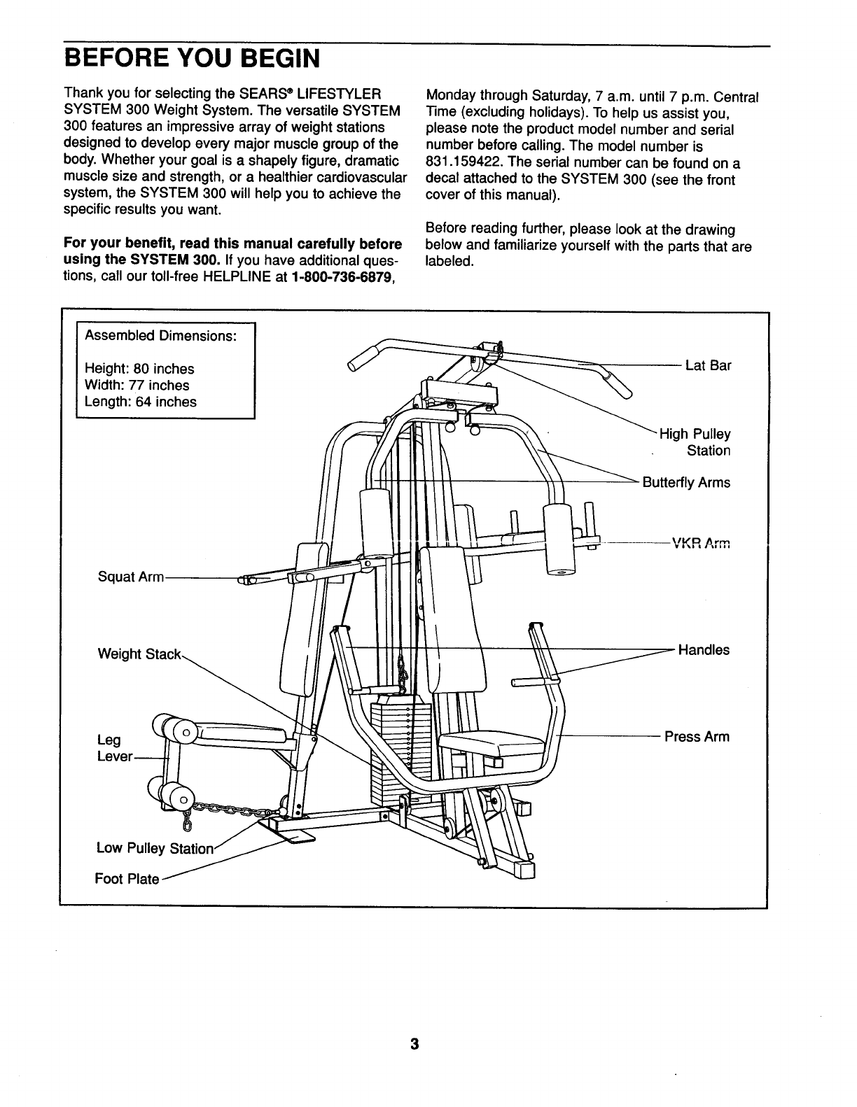
Before reading further, please look at the drawing
below and familiarize yourself with the parts that are
labeled.
Assembled Dimensions:
Height: 80 inches
Width: 77 inches
Length: 64 inches
Squat Arm
Weight
Lat Bar
High Pulley
Station
Butterfly Arms
VKR Arm
Handles
Leg Press Arm
Low Pulley
Foot Plate
3
ASSEMBLY
Due to the size and weight of the SYSTEM 300, it
should be assembled in the location where it will be
used. Place all parts of the SYSTEM 300 in a
cleared area and remove the packing materials; do
not dispose of the packing materials until assembly
is completed.
Assembly requires two people. Before beginning,
read each assembly step and look at each drawing
carefully. As you assemble the SYSTEM 300, make
sure that all parts are oriented exactly as shown in
the drawings. Tighten all parts as you attach them,
unless instructed to do otherwise.
For help identifying small parts, refer to the PART
IDENTIFICATION CHART attached to the center of
this manual.
•two adjustable wrenches
•a phillips screwdriver
• a flat screwdriver
•a rubber mallet.
Assembly requires these tools (not included):
Lubricant, such as grease or petroleum jelly, and a
small amount of soapy water are also needed.
To simplify assembly, the following tools are recom-
mended: A set of sockets, open- or closed-end
wrenches, or ratchet wrenches.
.
.
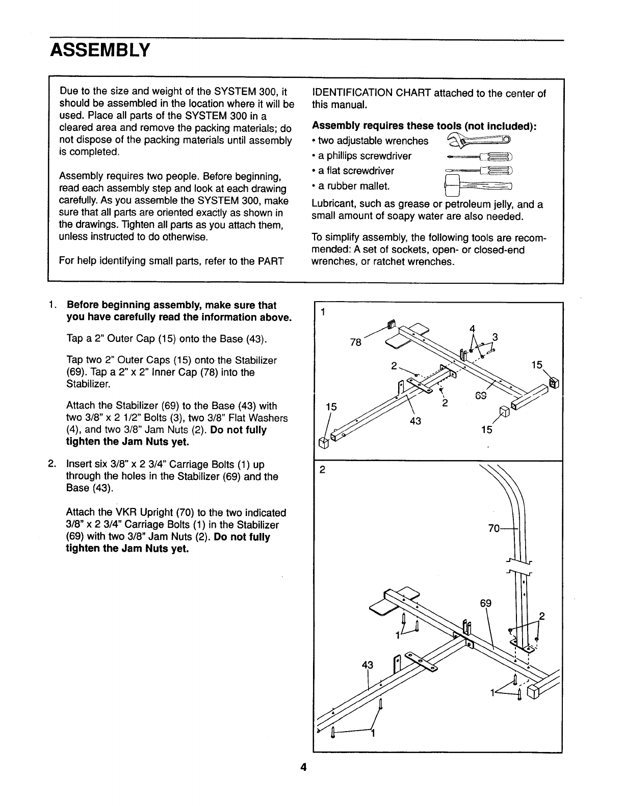
Before beginning assembly, make sure that
you have carefully read the information above.
Tap a 2" Outer Cap (15) onto the Base (43).
Tap two 2" Outer Caps (15) onto-the Stabilizer
(69). Tap a 2" x 2" Inner Cap (78) into the
Stabilizer.
Attach the Stabilizer (69) to the Base (43) with
two 3/8" x 2 1/2" Bolts (3), two 3/8" Flat Washers
(4), and two 3/8" Jam Nuts (2). Do not fully
tighten the Jam Nuts yet.
Insert six 3/8" x 2 3/4" Carriage Bolts (1) up
through the holes in the Stabilizer (69) and the
Base (43).
Attach the VKR Upright (70) to the two indicated
3/8" x 2 3/4" Carriage Bolts (1) in the Stabilizer
(69) with two 3/8" Jam Nuts (2). Do not fully
tighten the Jam Nuts yet.
15
78
43
43 15
15
\
r
4
3. 3
.
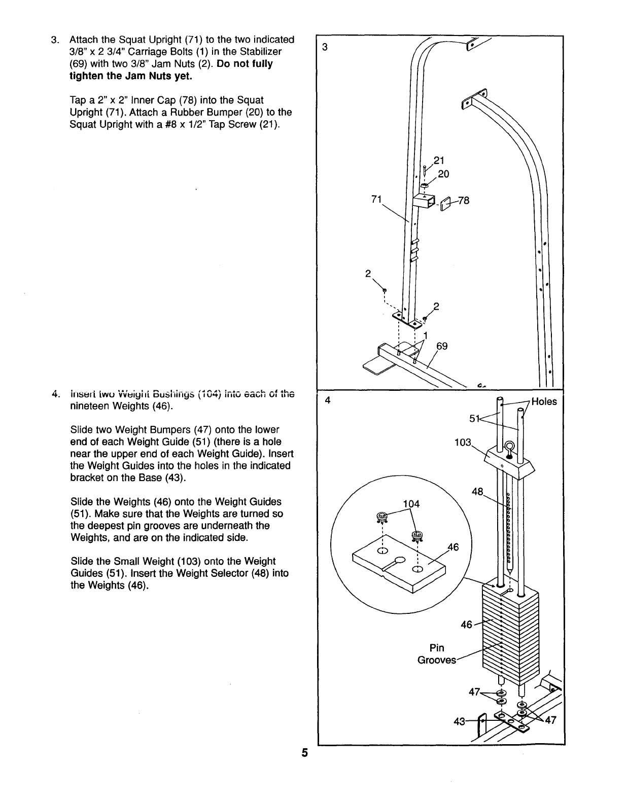
Attach the Squat Upright (71) to the two indicated
3/8" x 2 3/4" Carriage Bolts (1) in the Stabilizer
(69) with two 3/8" Jam Nuts (2). Do not fully
tighten the Jam Nuts yet.
Tap a 2" x 2" Inner Cap (78) into the Squat
Upright (71). Attach a Rubber Bumper (20) to the
Squat Upright with a #8 x 1/2" Tap Screw (21).
iilSUl[ 'l.wu ........vvulyl it Du_,'-'ll,..........ly_ !. ' v,.t! ,,:......_tv _.-,_.,L',Of .L.^ui_
nineteen Weights (46).
Slide two Weight Bumpers (47) onto the lower
end of each Weight Guide (51) (there is a hole
near the upper end of each Weight Guide). Insert
the Weight Guides into the holes in the indicated
bracket on the Base (43).
Slide the Weights (46) onto the Weight Guides
(51). Make sure that the Weights are turned so
the deepest pin grooves are underneath the
Weights, and are on the indicated side.
Slide the Small Weight (103) onto the Weight
Guides (51). Insert the Weight Selector (48) into
the Weights (46).
4
20
71
2\
i
: : 169
103_
Pin
.
°
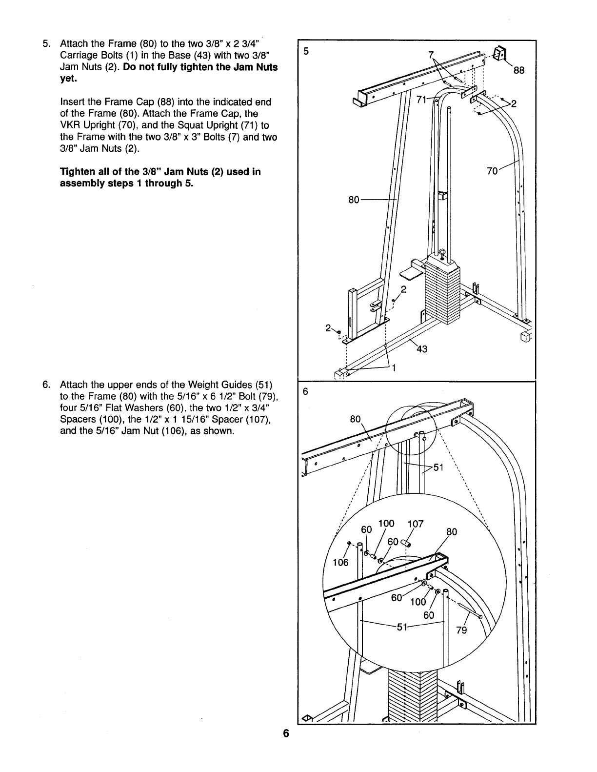
Attach the Frame (80) to the two 3/8" x 2 3/4"
Carriage Bolts (1) in the Base (43) with two 3/8"
Jam Nuts (2). Do not fully tighten the Jam Nuts
yet,
Insert the Frame Cap (88) into the indicated end
of the Frame (80). Attach the Frame Cap, the
VKR Upright (70), and the Squat Upright (71) to
the Frame with the two 3/8" x 3" Bolts (7) and two
3/8" Jam Nuts (2).
Tighten all of the 3/8" Jam Nuts (2) used in
assembly steps 1 through 5.
Attach the upper ends of the Weight Guides (51)
to the Frame (80) with the 5/16" x 6 1/2" Bolt (79),
four 5/16" Flat Washers (60), the two 1/2" x 3/4"
Spacers (100), the 1/2" x 1 15/16" Spacer (107),
and the 5/16" Jam Nut (106), as shown.
5
6
1
80
6
88
°
o
,
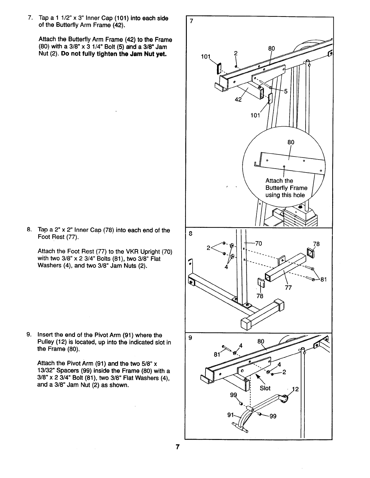
Tap a 11/2" x 3" Inner Cap (101) into each side
of the Butterfly Arm Frame (42).
Attach the Butterfly Arm Frame (42) to the Frame
(80) with a 3/8" x31/4" Bolt (5) and a 3/8" Jam
Nut (2). Do not fully tighten the Jam Nut yet.
Tap a 2" x 2" Inner Cap (78) into each end of the
Foot Rest (77).
Attach the Foot Rest (77) to the VKR Upright (70)
with two 3/8" x 2 3/4" Bolts (81), two 3/8" Flat
Washers (4), and two 3/8" Jam Nuts (2).
Insert the end of the Pivot Arm (91) where the
Pulley (12) is located, up into the indicated slot in
the Frame (80).
Attach the Pivot Arm (91) and the two 5/8" x
13/32" Spacers (99) inside the Frame (80) with a
3/8" x 2 3/4" Bolt (81), two 3/8" Flat Washers (4),
and a 3/8" Jam Nut (2) as shown.
7
8
2
101\
101
Frame
78
78
7
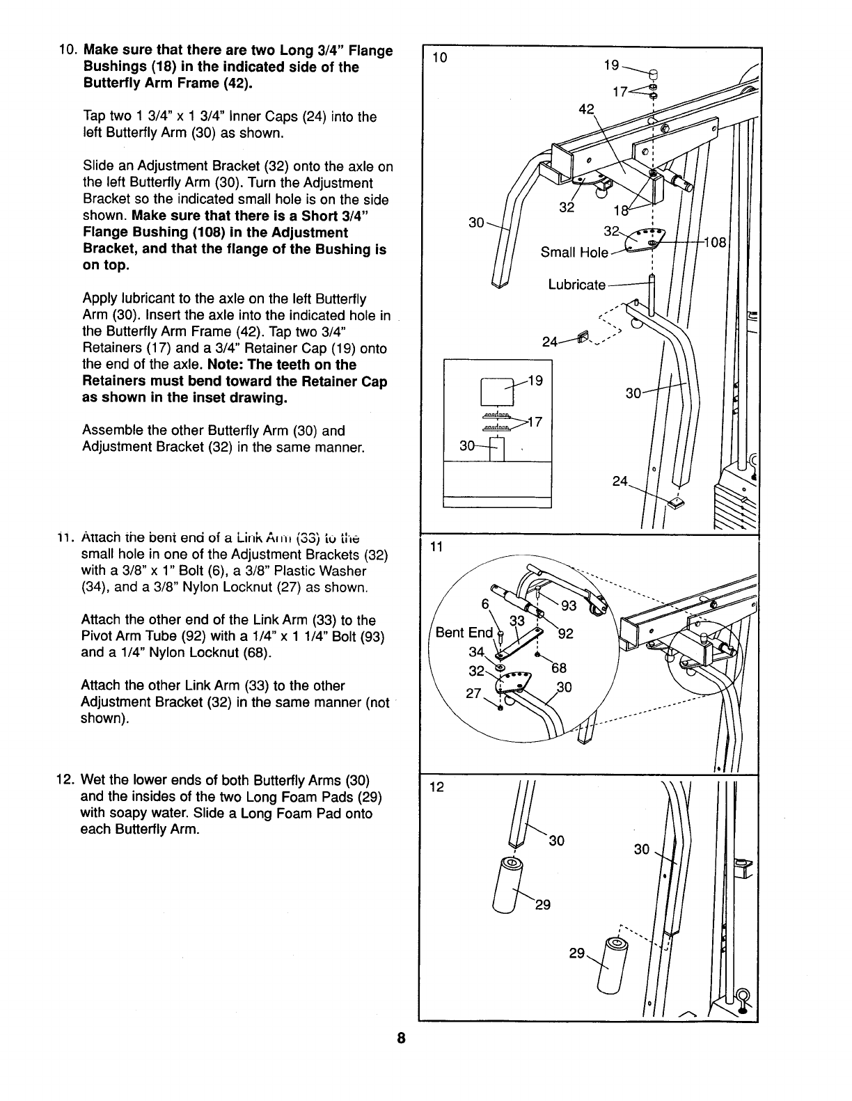
10. Make sure that there are two Long 3/4" Flange
Bushings (18) in the indicated side of the
Butterfly Arm Frame (42).
Tap two 1 3/4" x 1 3/4" Inner Caps (24) into the
left Butterfly Arm (30) as shown.
Slide an Adjustment Bracket (32) onto the axle on
the left Butterfly Arm (30). Turn the Adjustment
Bracket so the indicated small hole is on the side
shown. Make sure that there is a Short 3/4"
Flange Bushing (108) in the Adjustment
Bracket, and that the flange of the Bushing is
on top.
Apply lubricant to the axle on the left Butterfly
Arm (30). Insert the axle into the indicated hole in
the Butterfly Arm Frame (42). Tap two 3/4"
Retainers (17) and a 3/4" Retainer Cap (19) onto
the end of the axle. Note: The teeth on the
Retainers must bend toward the Retainer Cap
as shown in the inset drawing.
Assemble the other Butterfly Arm (30) and
Adjustment Bracket (32) in the same manner.
il. Attach the bent end of aLink A_rl_(33) tu the
small hole in one of the Adjustment Brackets (32)
with a 3/8" x 1" Bolt (6), a 3/8" Plastic Washer
(34), and a 3/8" Nylon Locknut (27) as shown.
Attach the other end of the Link Arm (33) to the
Pivot Arm Tube (92) with a 1/4" x 1 1/4" Bolt (93)
and a 1/4" Nylon Locknut (68).
Attach the other Link Arm (33) to the other
Adjustment Bracket (32) in the same manner (not
shown).
12. Wet the lower ends of both Butterfly Arms (30)
and the insides of the two Long Foam Pads (29)
with soapy water. Slide a Long Foam Pad onto
each Butterfly Arm.
8
10
11
12
34\
32\
24
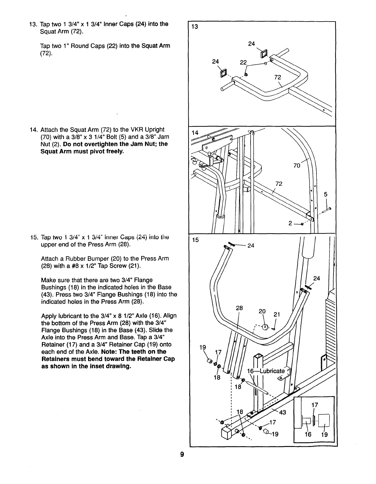
13. Tap two 1 3/4" x 1 3/4" Inner Caps (24) into the
Squat Arm (72).
Tap two 1" Round Caps (22) into the Squat Arm
(72).
14. Attach the Squat Arm (72) to the VKR Upright
(70) with a 3/8" x 3 1/4" Bolt (5) and a 3/8" Jam
Nut (2), Do not overtighten the Jam Nut; the
Squat Arm must pivot freely.
15. Tap two 1 3/4" x 1 3/4" inner Caps (24) into the
upper end of the Press Arm (28).
Attach a Rubber Bumper (20) to the Press Arm
(28) with a #8 x 1/2" Tap Screw (21).
Make sure that there are two 3/4" Flange
Bushings (18) in the indicated holes in the Base
(43). Press two 3/4" Flange Bushings (18) into the
indicated holes in the Press Arm (28).
Apply lubricant to the 3/4" x 8 1/2" Axle (16). Align
the bottom of the Press Arm (28) with the 3/4"
Flange Bushings (18) in the Base (43). Slide the
Axle into the Press Arm and Base. Tap a 3/4"
Retainer (17) and a 3/4" Retainer Cap (19) onto
each end of the Axle. Note: The teeth on the
Retainers must bend toward the Retainer Cap
as shown in the inset drawing.
13
15
19
24
18
22
18
18
24
24
20
72
21
9
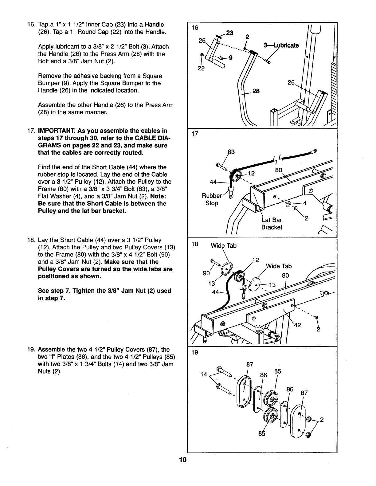
16. Tap a 1" x 1 1/2" Inner Cap (23) into a Handle
(26). Tap a 1" Round Cap (22) into the Handle.
Apply lubricant to a 3/8" x 2 1/2" Bolt (3). Attach
the Handle (26) to the Press Arm (28) with the
Bolt and a 3/8" Jam Nut (2).
Remove the adhesive backing from a Square
Bumper (9). Apply the Square Bumper to the
Handle (26) in the indicated location.
Assemble the other Handle (26) to the Press Arm
(28) in the same manner.
17. IMPORTANT: As you assemble the cables in
steps 17 through 30, refer to the CABLE DIA-
GRAMS on pages 22 and 23, and make sure
that the cables are correctly routed.
Find the end of the Short Cable (44) where the
rubber stop is located. Lay the end of the Cable
over a 3 1/2" Pulley (12). Attach the Pulley to the
Frame (80) with a 3/8" x 3 3/4" Bolt (83), a 3/8"
Flat Washer (4), and a 3/8" Jam Nut (2). Note:
Be sure that the Short Cable is between the
Pulley and the lat bar bracket.
18. Lay the Short Cable (44) over a 3 1/2" Pulley
(12). Attach the Pulley and two Pulley Covers (13)
to the Frame (80) with the 3/8" x 4 1/2" Bolt (90)
and a 3/8" Jam Nut (2). Make sure that the
Pulley Covers are turned so the widetabs are
positioned as shown.
See step 7. Tighten the 3/8" Jam Nut (2) used
in step 7.
19. Assemble the two 4 1/2" Pulley Covers (87), the
two "1" Plates (86), and the two 4 1/2" Pulleys (85)
with two 3/8" x 1 3/4" Bolts (14) and two 3/8" Jam
Nuts (2).
16
17
18
Rubber
Stop
Lat Bar
Bracket
Wide Tab
90
12 Wide Tab
80
2
19
87
14 7_ 86 85
10
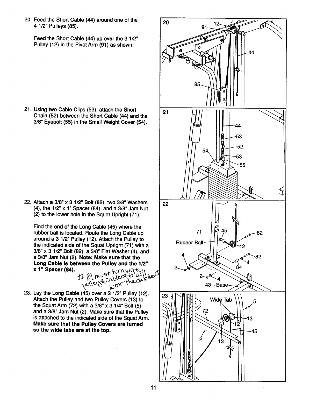
20. Feed the Short Cable (44) around one of the
4 1/2" Pulleys (85).
Feed the Short Cable (44) up over the 3 1/2"
Pulley (12) in the Pivot Arm (91) as shown.
21. Using two Cable Clips (53), attach the Short
Chain (52) between the Short Cable (44) and the
3/8" Eyebolt (55) in the Small Weight Cover (54).
22. Attach a 3/8" x 3 1/2" Bolt (82), two 3/8" Washers
(4), the 1/2" x 1" Spacer (84), and a 3/8" Jam Nut
(2) to the lower hole in the Squat Upright (71).
Find the end of the Long Cable (45) where the
rubber ball is located. Route the Long Cable up
around a 3 1/2" Pulley (12). Attach the Pulley to
the indicated side of the Squat Upright (71) with a
3/8"x 3 1/2" Bolt (82), a 3/8" Flat Washer (4), and
a 3/8" Jam Nut (2). Note: Make sure that the
Long Cable Is between the Pulley and the 1/2"
x 1" Spacer (84). , .... u_ _-_r__\ .._,_
_t r_A_.'o_,_ _" T_ _'_
23. Lay the Long Cable (45) over a 3 1/2" Pulley (12).
Attach the Pulley and two Pulley Covers (13) to
the Squat Arm (72) with a 3/8" x 3 1/4" Bolt (5)
and a 3/8" Jam Nut (2). Make sure that the Pulley
is attached to the indicated side of the Squat Arm.
Make sure that the Pulley Covers are turned
so the wide tabs are at the top.
11
20 i _.-44
j
2, ://!V
_--! -- -44
_ _53
55
22 ""JJ I
71-- _ 45 _182
Rubber B£11-_ l_. _12
4,
I1_ WideTab!!',5
l 72 .
t_ _ -;------45
1:3 '
i
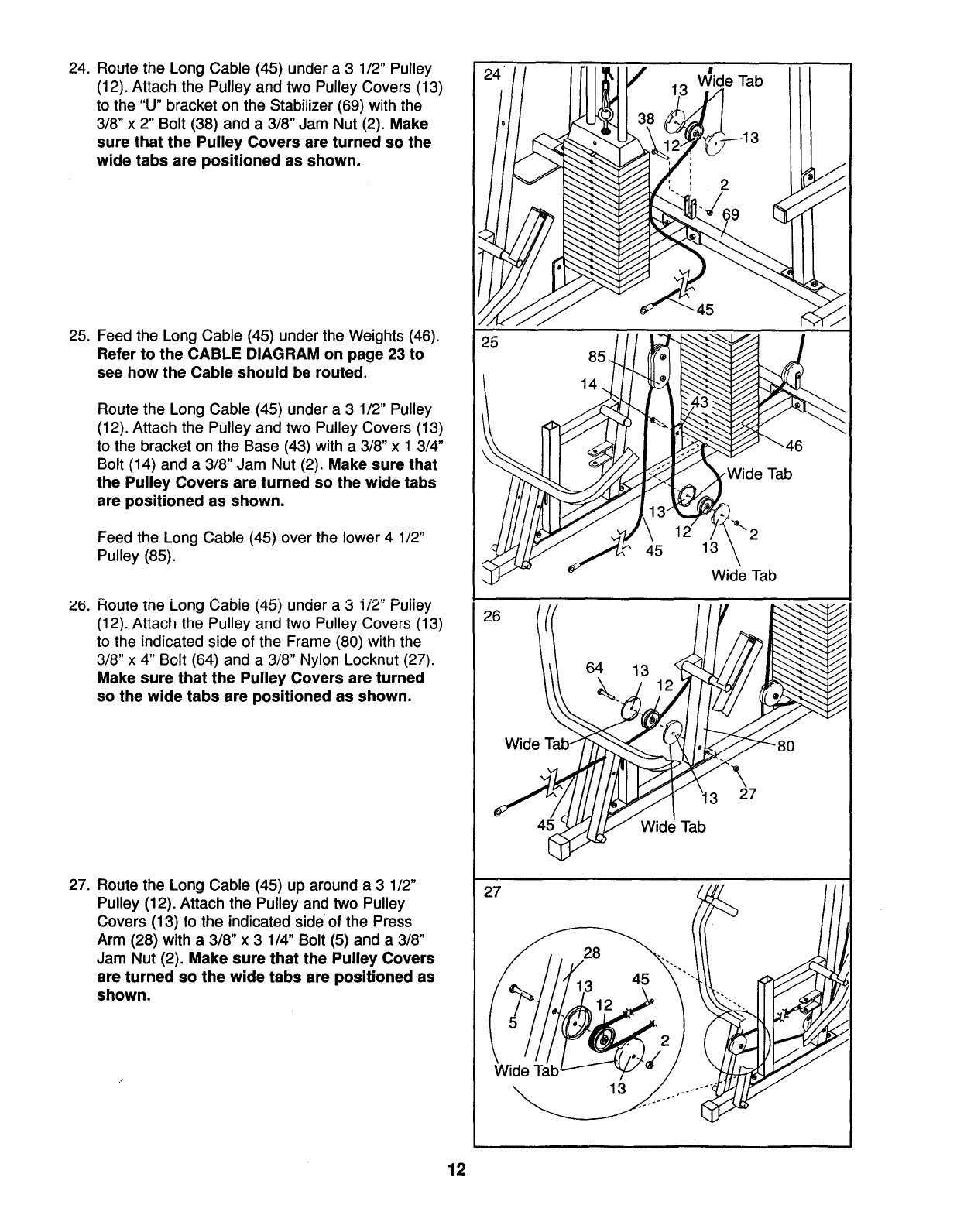
24. Route the Long Cable (45) under a 3 1/2" Pulley
(12). Attach the Pulley and two Pulley Covers (13)
to the "U" bracket on the Stabilizer (69) with the
3/8" x 2" Bolt (38) and a 3/8" Jam Nut (2). Make
sure that the Pulley Covers are turned so the
wide tabs are positioned as shown.
25. Feed the Long Cable (45) under the Weights (46).
Refer to the CABLE DIAGRAM on page 23 to
see how the Cable should be routed.
Route the Long Cable (45) under a 3 1/2" Pulley
(12). Attach the Pulley and two Pulley Covers (13)
to the bracket on the Base (43) with a 3/8" x 1 3/4"
Bolt (14) and a 3/8" Jam Nut (2). Make sure that
the Pulley Covers are turned so the wide tabs
are positioned as shown,
Feed the Long Cable (45) over the lower 4 1/2"
Pulley (85).
Zt_. Route _ne Long Cabie (45) under a 3 1/2" Puiiey
(12). Attach the Pulley and two Pulley Covers (13)
to the indicated side of the Frame (80) with the
3/8" x 4" Bolt (64) and a 3/8" Nylon Locknut (27).
Make sure that the Pulley Covers are turned
so the wide tabs are positioned as shown.
27. Route the Long Cable (45) up around a 3 1/2"
Pulley (12). Attach the Pulley and two Pulley
Covers (13) to the indicated side of the Press
Arm (28) with a 3/8" x 3 1/4" Bolt (5) and a 3/8"
Jam Nut (2). Make sure that the Pulley Covers
are turned so the wide tabs are positioned as
shown.
25
|
Wide Tab
_2-13
i- 'i6cp
Tab
Wide Tab
26
Wide
64 13
\27
45 Wide Tab
27
Wide Tab
12
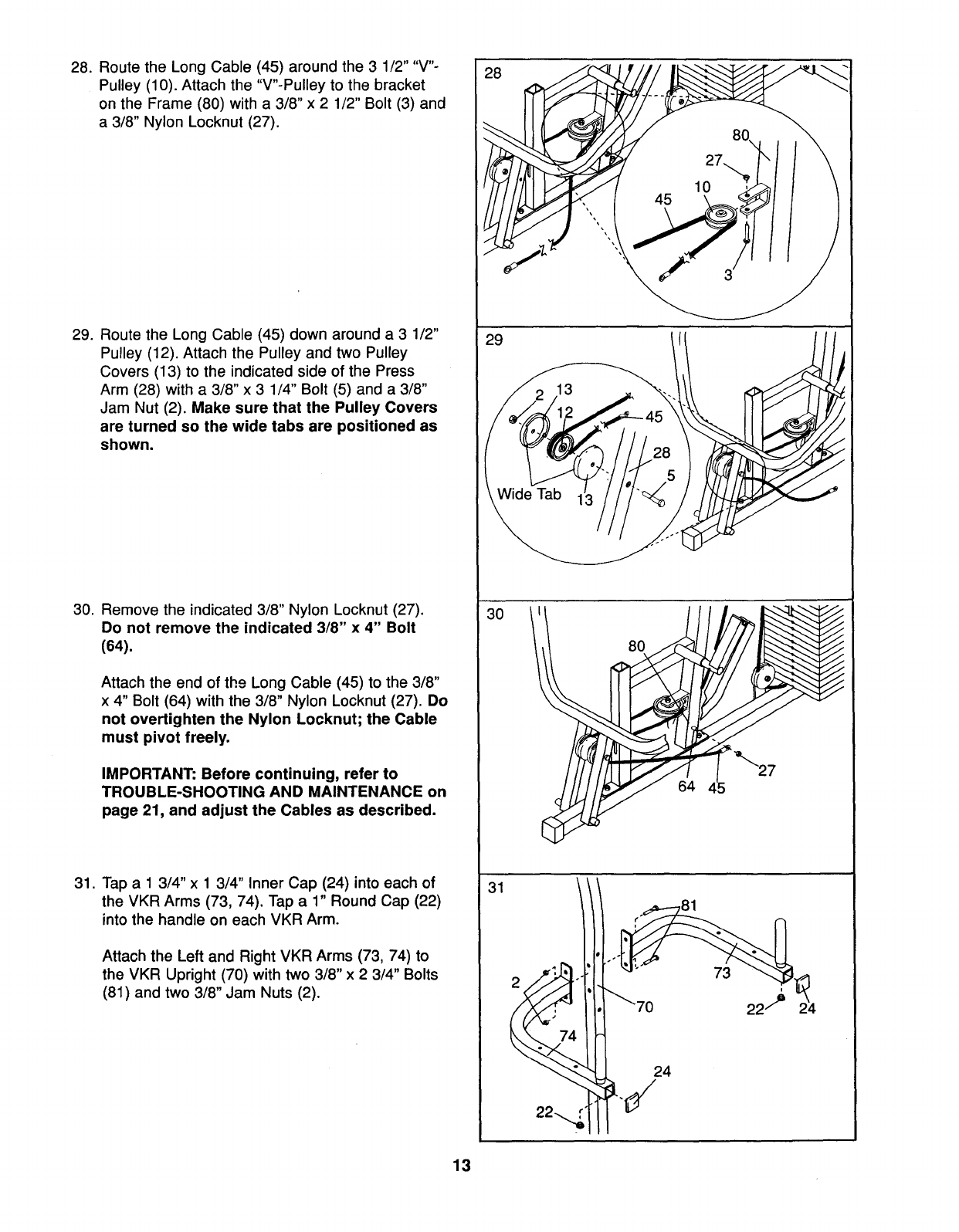
28. Route the Long Cable (45) around the 3 1/2" "V"-
Pulley (10). Attach the "V"-Pulley to the bracket
on the Frame (80) with a 3/8" x 2 1/2" Bolt (3) and
a 3/8" Nylon Locknut (27).
29. Route the Long Cable (45) down around a 3 1/2"
Pulley (12). Attach the Pulley and two Pulley
Covers (13) to the indicated side of the Press
Arm (28) with a 3/8" x 3 1/4" Bolt (5) and a 3/8"
Jam Nut (2). Make sure that the Pulley Covers
are turned so the wide tabs are positioned as
shown.
30. Remove the indicated 3/8" Nylon Locknut (27).
Do not remove the indicated 3/8" x 4" Bolt
(64).
Attach the end of the Long Cable (45) to the 3/8"
x4" Bolt (64) with the 3/8" Nylon Locknut (27). Do
not overUghten the Nylon Locknut; the Cable
must pivot freely.
IMPORTANT: Before continuing, refer to
TROUBLE-SHOOTING AND MAINTENANCE on
page 21, and adjust the Cables as described.
31. Tap a 1 3/4" x 1 3/4" Inner Cap (24) into each of
the VKR Arms (73, 74). Tap a 1" Round Cap (22)
into the handle on each VKR Arm.
Attach the Left and Right VKR Arms (73, 74) to
the VKR Upright (70) with two 3/8" x 2 3/4" Bolts
(81) and two 3/8" Jam Nuts (2).
28
29
13
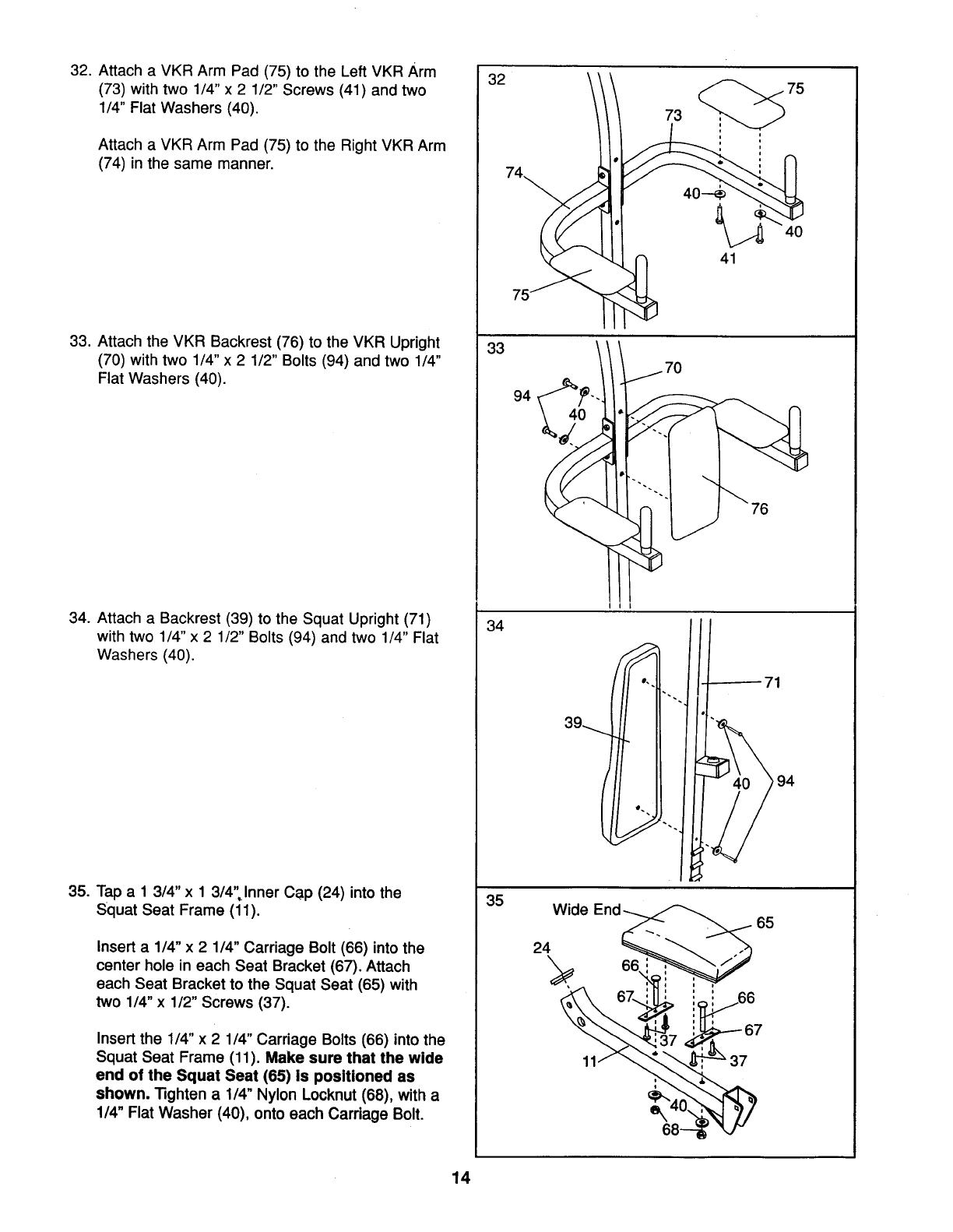
32. Attach a VKR Arm Pad (75) to the Left VKR Arm
(73) with two 1/4" x 2 1/2" Screws (41) and two
1/4" Flat Washers (40).
Attach a VKR Arm Pad (75) to the Right VKR Arm
(74) in the same manner.
33. Attach the VKR Backrest (76) to the VKR Upright
(70) with two 1/4" x 2 1/2" Bolts (94) and two 1/4"
Flat Washers (40).
34. Attach a Backrest (39) to the Squat Upright (71)
with two 1/4" x 2 1/2" Bolts (94) and two 1/4" Flat
Washers (40).
35. Tap a 1 3/4" x 1 3/4"Jnner Cap (24) into the
Squat Seat Frame (11).
Insert a 1/4" x 2 1/4" Carriage Bolt (66) into the
center hole in each Seat Bracket (67). Attach
each Seat Bracket to the Squat Seat (65) with
two 1/4" x 1/2" Screws (37).
Insert the 1/4" x 21/4" Carriage Bolts (66) into the
Squat Seat Frame (11). Make sure that the wide
end of the Squat Seat (65) is positioned as
shown. _ghten a 1/4" Nylon Locknut (68), with a
1/4" Flat Washer (40), onto each Carriage Bolt.
32
75
33
94
34
35
41
76
24Wide End_ 65
67._! I: i_i /66
14
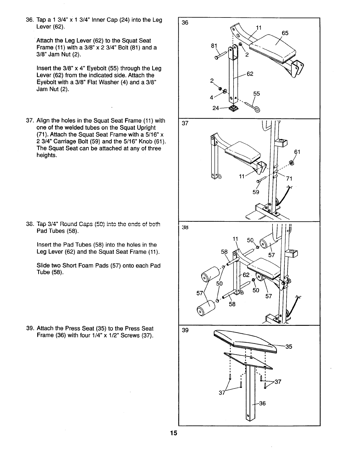
36. Tap a 1 3/4" x t 3/4" Inner Cap (24) into the Leg
Lever (62).
Attach the Leg Lever (62) to the Squat Seat
Frame (11) with a 3/8" x 2 3/4" Bolt (81) and a
3/8" Jam Nut (2).
Insert the 3/8" x 4" Eyebolt (55) through the Leg
Lever (62) from the indicated side. Attach the
Eyebolt with a 3/8" Flat Washer (4) and a 3/8"
Jam Nut (2).
37. Align the holes in the Squat Seat Frame (11) with
one of the welded tubes on the Squat Upright
(71). Attach the Squat Seat Frame with a 5/16" x
2 3/4" Carriage Bolt (59) and the 5/16" Knob (61).
The Squat Seat can be attached at any of three
heights.
38. Tap 3/4" Round Caps (50) intc the ends of both
Pad Tubes (58).
Insert the Pad Tubes (58) into the holes in the
Leg Lever (62) and the Squat Seat Frame (11).
Slide two Short Foam Pads (57) onto each Pad
Tube (58).
39. Attach the Press Seat (35) to the Press Seat
Frame (36) with four 1/4" x 1/2" Screws (37).
36
37
3_
57I
39
81
11 65
2
55
11
61
59
11
58
5O
58
35
3 37
15
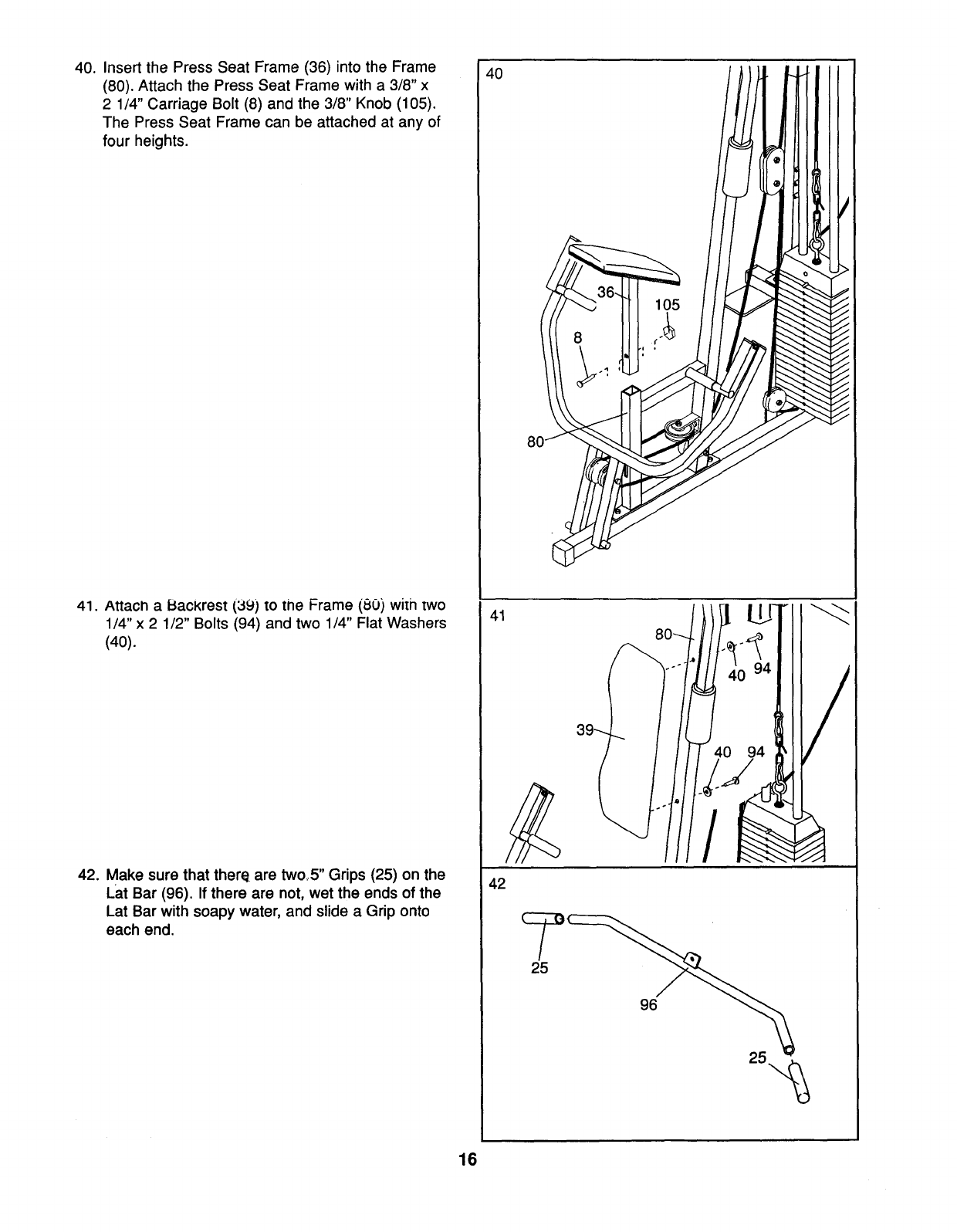
40. Insert the Press Seat Frame (36) into the Frame
(80). Attach the Press Seat Frame with a 3/8" x
2 1/4" Carriage Bolt (8) and the 3/8" Knob (105).
The Press Seat Frame can be attached at any of
four heights.
41. Attacrl a BacKrest (39) to ti_e Frame (80) with lwo
1/4" x 2 1/2" Bolts (94) and two 1/4" Flat Washers
(40).
42. Make sure that there, are two,.5" Grips (25) on the
Lat Bar (96). If there are not, wet the ends of the
Lat Bar with soapy water, and slide a Grip onto
each end.
4O
41
42
8
25
96
!
>
f
f
J
f
J
J
J
f
f
f
f
f
f
J
f
J
J
J
J
/
16
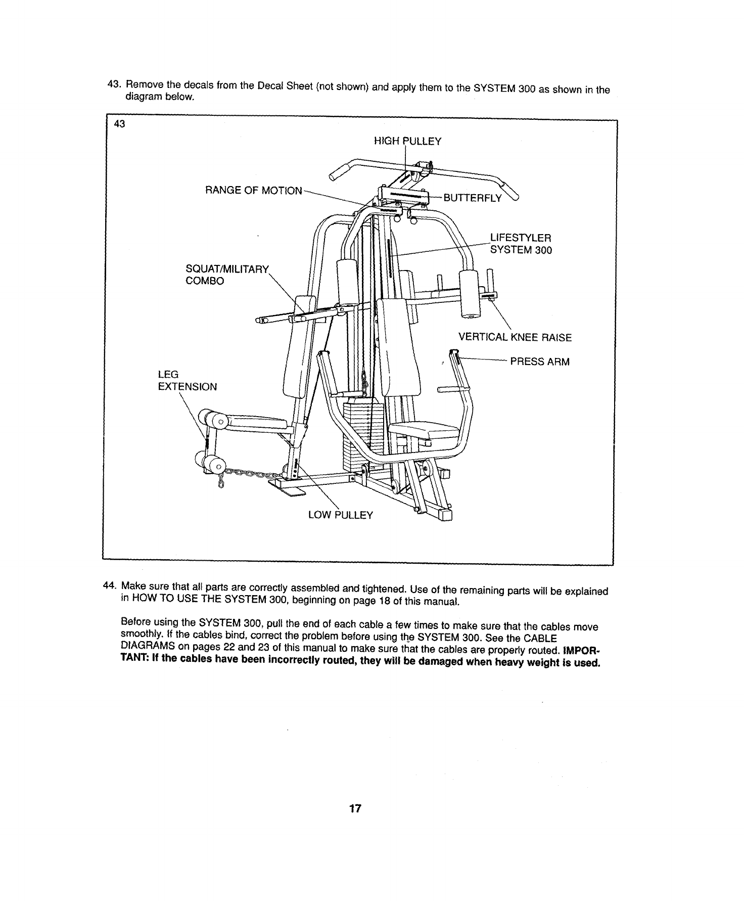
43. Remove the decals from the Decal Sheet (not shown) and apply them to the SYSTEM 300 as shown in the
diagram below.
43
HIGH PULLEY
RANGE OF
SQUAT/MILITARY
COMBO
LEG
EXTENSION
\
LIFESTYLER
300
VERTICAL KNEE RAISE
PRESS ARM
LOW PULLEY
44. Make sure that all parts are correctly assembled and tightened. Use of the remaining parts will be explained
in HOW TO USE THE SYSTEM 300, beginning on page 18 of this manual.
Before using the SYSTEM 300, pull the end of each cable a few times to make sure that the cables move
smoothly, if the cables bind, correct the problem before using the SYSTEM 300. See the CABLE
DIAGRAMS on pages 22 and 23 of this manual to make sure that the cables are properly routed. IMPOR-
TANT: If the cables have been incorrectly routed, they will be damaged when heavy weight is used.
17

HOW TO USE THE SYSTEM 300
The instructions below describe how each part of the SYSTEM 300 can be adjusted. Refer to the EXERCISE
GUIDE accompanying this manual for exercise guidelines, and to see how the SYSTEM 300 should be set up
for each exercise.
IMPORTANT: When attaching the lat bar or nylon strap, make sure that the attachments are in the cor-
rect starting position for the exercise to be performed. If there is any slack in the cable or chain as an
exercise is performed, the effectiveness of the exercise will be reduced.
SELECTING A WEIGHT SETTING
The weight stack includes twenty 10 pound weights.
To change the weight setting, insert the Weight Pin
(49) under the desired Weight (46). Make sure to
insert the Weight Pin until the bent end is touching
the Weights, and turn the bent end downward. The
weight setting can be increased from 10 pounds to
200 pounds in increments of 10 pounds. Note:
Because of the cables and pulleys, the actual
amount of resistance at each exercise station may
vary from the weight setting. See the WEIGHT
RESISTANCE CHART on page 20 of this manual.
US.ING THE BUTTERFLY ARMS
If desired, the starting position of the Butterfly Arms
(30) can be adjusted. Pull one of the Spring-Loaded
Knobs (31), so that the Butterfly Arm can pivot.
Release the Knob when the Butterfly Arm is in the
desired position. Pivot the Butterfly Arm back and
forth slightly to make sure that it is locked in place.
Adjust the other Butterfly Arm in the same manner.
WARNING: When using the Butterfly Arms (30),
always apply equal force to both Butterfly Arms.
Never use only one Butterfly Arm. Doing so could
cause permanent damage.
REMOVING AND ATTACHING THE SQUAT SEAT
For some exercises, the Squat Seat (65) must be
removed. Make sure that the long chain is not
attached to the Leg Lever (62). Remove the 5/16"
Knob (61) and the 5/16" x 2 3/4" Carriage Bolt (59).
Lift the Squat Seat Frame (11) off the Squat Upright
(71).
To attach the Squat Seat (65), align the holes in the
Squat Seat Frame (11) with one of the welded tubes
on the Squat Upright (71). Attach the Squat Seat
Frame with the 5/16" x 2 3/4" Carriage Bolt (59) and
the 5/16" Knob (61). The Squat Seat can be attached
at any of three heights.
18
49
46
65
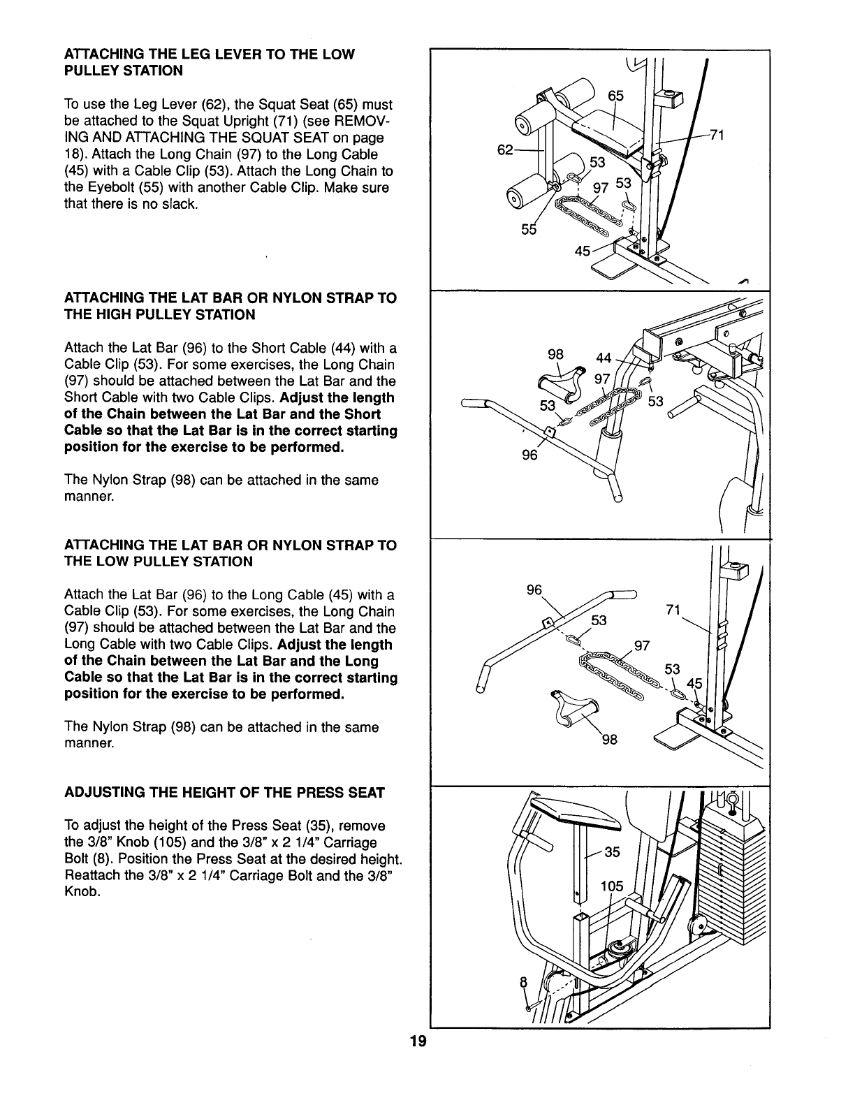
ATTACHING THE LEG LEVER TO THE LOW
PULLEY STATION
To use the Leg Lever (62), the Squat Seat (65) must
be attached to the Squat Upright (71) (see REMOV-
ING AND ATTACHING THE SQUAT SEAT on page
18). Attach the Long Chain (97) to the Long Cable
(45) with a Cable Clip (53). Attach the Long Chain to
the Eyebolt (55) with another Cable Clip. Make sure
that there is no slack.
ATTACHING THE LAT BAR OR NYLON STRAP TO
THE HIGH PULLEY STATION
Attach the Lat Bar (96) to the Short Cable (44) with a
Cable Clip (53). For some exercises, the Long Chain
(97) should be attached between the Lat Bar and the
Short Cable with two Cable Clips. Adjust the length
of the Chain between the Lat Bar and the Short
Cable so that the Lat Bar is in the correct starting
position for the exercise to be performed,
The Nylon Strap (98) can be attached in the same
manner.
ATTACHING THE LAT BAR OR NYLON STRAP TO
THE LOW PULLEY STATION
Attach the Lat Bar (96) to the Long Cable (45) with a
Cable Clip (53). For some exercises, the Long Chain
(97) should be attached between the Lat Bar and the
Long Cable with two Cable Clips. Adjust the length
of the Chain between the Lat Bar and the Long
Cable so that the Lat Bar is in the correct starting
position for the exercise to be performed.
The Nylon Strap (98) can be attached in the same
manner.
ADJUSTING THE HEIGHT OF THE PRESS SEAT
To adjust the height of the Press Seat (35), remove
the 3/8" Knob (105) and the 3/8" x 2 1/4" Carriage
Bolt (8). Position the Press Seat at the desired height.
Reattach the 3/8" x 2 1/4" Carriage Bolt and the 3/8"
Knob.
19
6 65_ 71
55 45_ ._
98 44
53
96
96
I.II 105JII I/
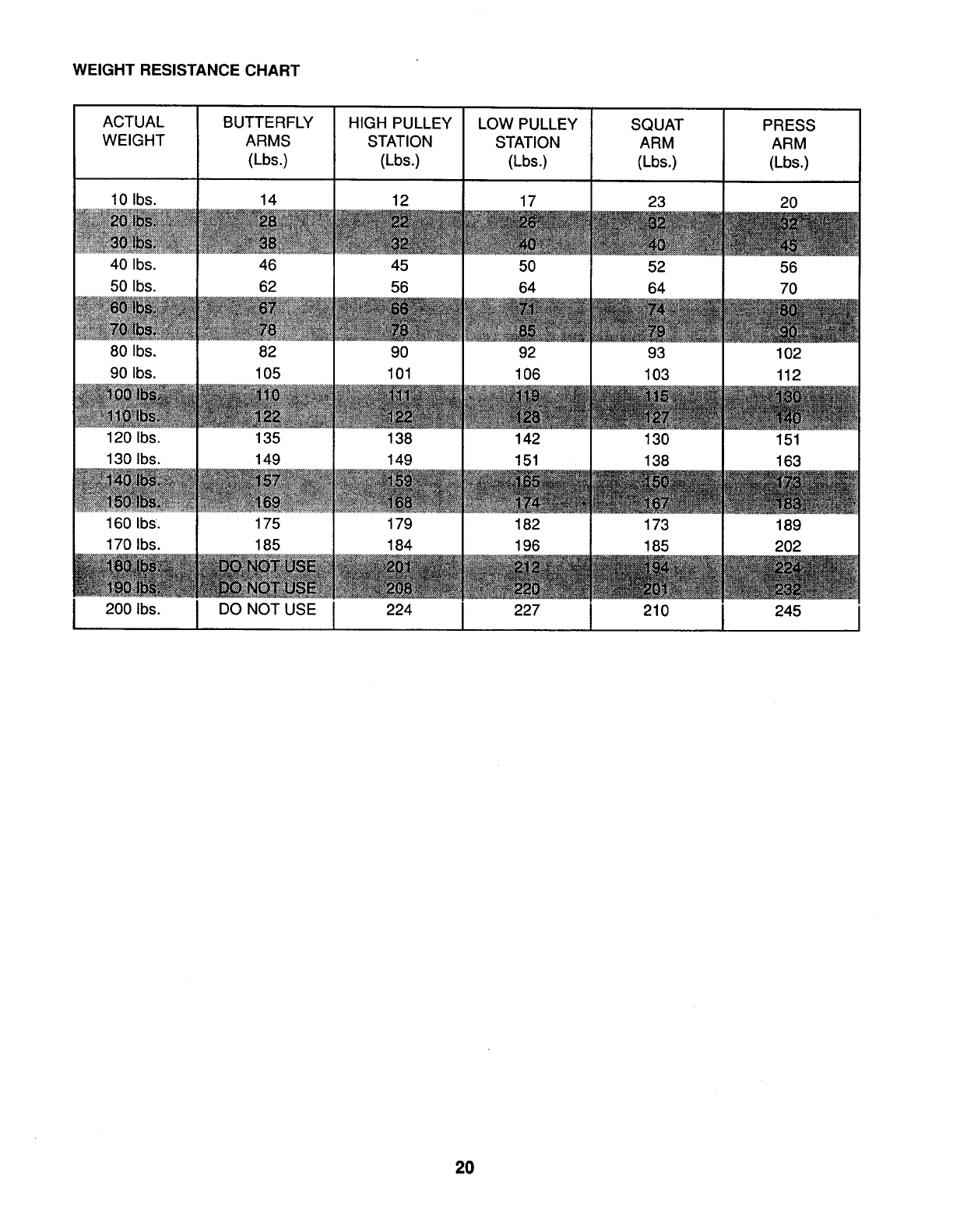
WEIGHT RESISTANCE CHART
ACTUAL
WEIGHT
10 Ibs.
40 Ibs.
50 Ibs.
80 Ibs.
90 Ibs.
120 Ibs.
130 Ibs.
200 Ibs.
BUTTERFLY
ARMS
(Lbs.)
14
46
62
82
105
135
149
DO NOT USE
HIGH PULLEY
STATION
(Lbs.)
12
45
56
9O
101
138
149
224
LOW PULLEY
STATION
(Lbs.)
17
5O
64
92
106
142
151
227
SQUAT
ARM
(Lbs.)
23
52
64
93
103
130
138
210
PRESS
ARM
(Lbs.)
20
56
70
102
112
151
163
245
20
TROUBLE-SHOOTING AND MAINTENANCE
Inspect and tighten all parts each time you use the SYSTEM 300. Replace all worn parts immediately (see
ORDERING REPLACEMENT PARTS on the back cover of this manual). The SYSTEM 300 can be cleaned
using a damp cloth and a mild detergent. Do not use solvents or abrasives.
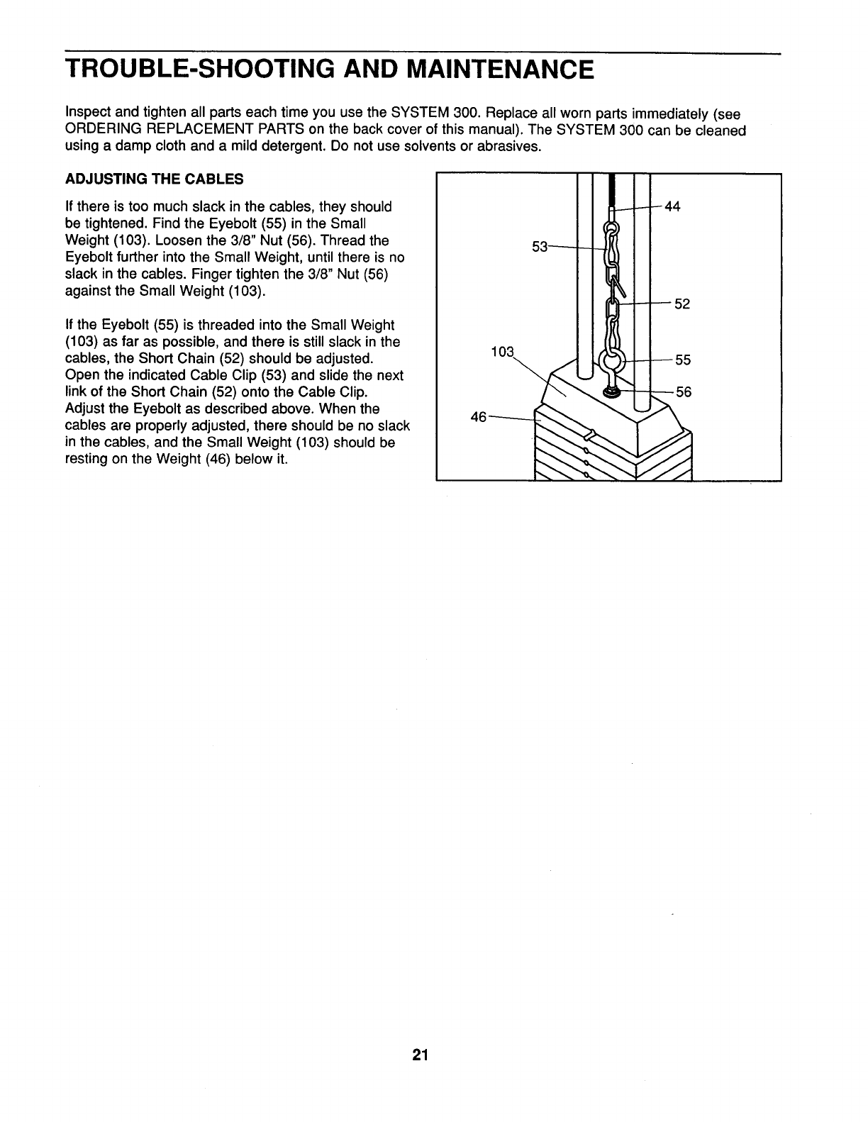
ADJUSTING THE CABLES
If there is too much slack in the cables, they should
be tightened. Find the Eyebolt (55) in the Small
Weight (103). Loosen the 3/8" Nut (56). Thread the
Eyebolt further into the Small Weight, until there is no
slack in the cables. Finger tighten the 3/8" Nut (56)
against the Small Weight (103).
If the Eyebolt (55) is threaded into the Small Weight
(103) as far as possible, and there is still slack in the
cables, the Short Chain (52) should be adjusted.
Open the indicated Cable Clip (53) and slide the next
link of the Short Chain (52) onto the Cable Clip.
Adjust the Eyebolt as described above. When the
cables are properly adjusted, there should be no slack
in the cables, and the Small Weight (103) should be
resting on the Weight (46) below it.
_----44
53_
103
-- 52
i---55
21
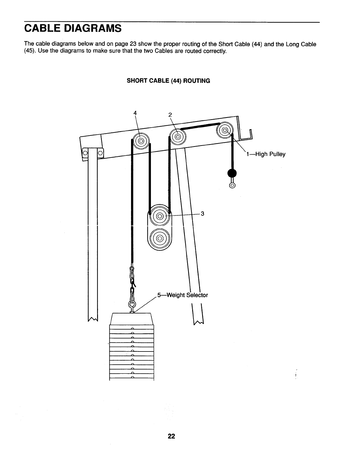
CABLE DIAGRAMS
The cable diagrams below and on page 23 show the proper routing of the Short Cable (44) and the Long Cable
(45). Use the diagrams to make sure that the two Cables are routed correctly.
SHORT CABLE (44) ROUTING
4 2
t-1
t_
j 5_Weight Selector
gh Pulley
22
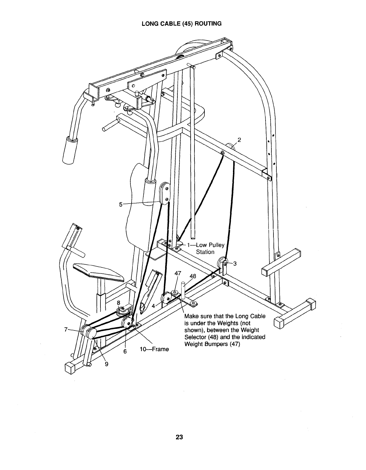
LONG CABLE (45) ROUTING
2
1--Low Pulley
Station
47
61O--Frame
Make sure that the Long Cable
is under the Weights (not
shown), between the Weight
Selector (48) and the indicated
Weight Bumpers (47)
23
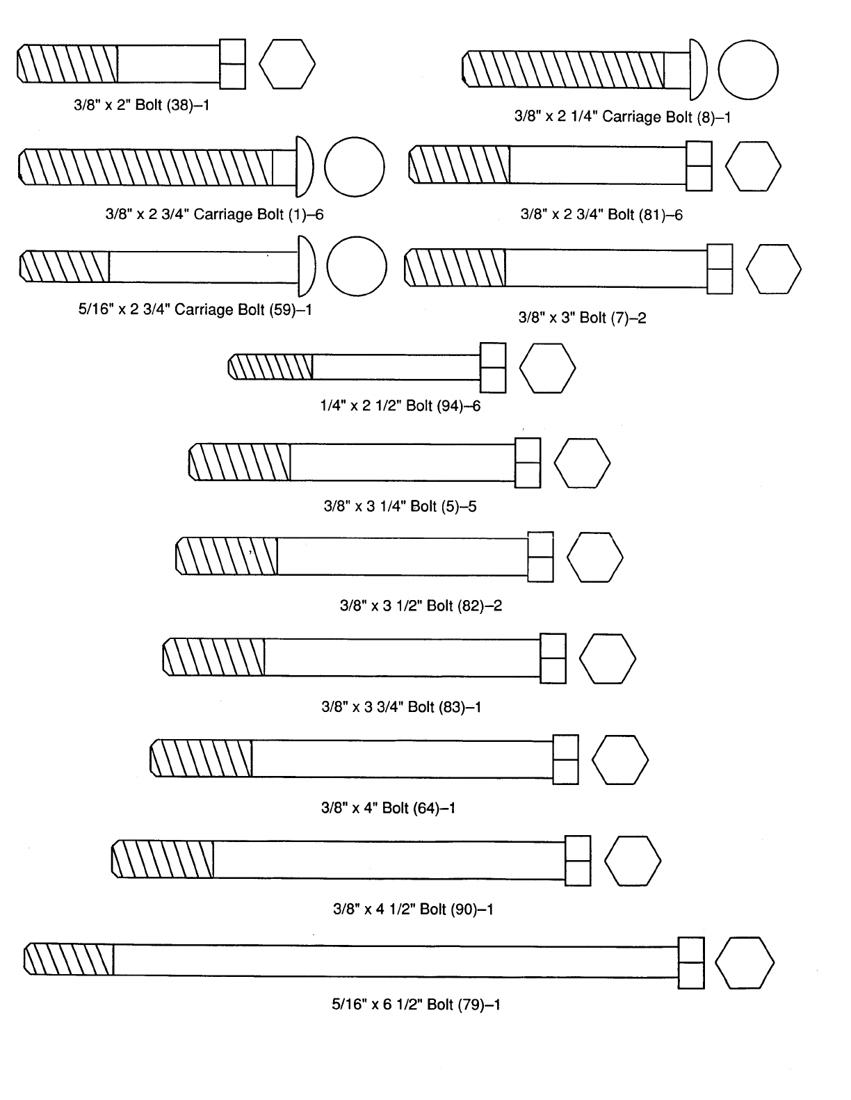
This chart is provided to help you identify the small parts used in assembly. Note: Some parts may have been pre-
assembled for shipping purposes; if you cannot find a part in the parts bags, check the frame to see if it has been pre-
assembled.
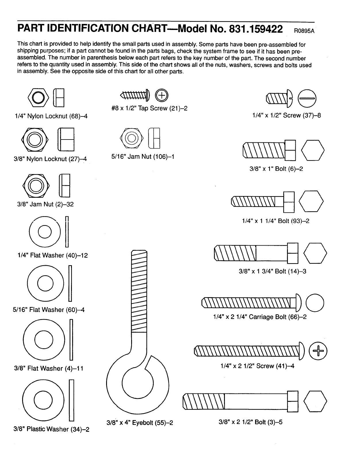
PART IDENTIFICATION CHART---Model No. 831.159422 F_o89sA
This chart is provided to help identify the small parts used in assembly. Some parts have been pre-assembled for
shipping purposes; if a part cannot be found in the parts bags, check the system frame to see if it has been pre-
assembled. The number in parenthesis below each part refers to the key number of the part. The second number
refers to the quantity used in assembly. This side of the chart shows all of the nuts, washers, screws and bolts used
in assembly. See the opposite side of this chart for all other parts.
1/4" Nylon Locknut (68)-4
3/8" Nylon Locknut (27)-4
3/8" Jam Nut (2)-32
1/4" Flat Washer (40)-12
5/16" Flat Washer (60)-4
3/8" Flat Washer (4)-11
w
3/8" Plastic Washer (34)-2
#8 x 1/2" Tap Screw (21)-2
5/16" Jam Nut (106)-1
1/4"x 1/2" Screw (37)-8
0
3/8" x 1" Bolt (6)-2
1/4"x 1 1/4" Bolt (93)-2
J
J
I
I
I
I
J
J
I
J
f
I
J
I
J
I
J
J
3/8" x 1 3/4" Bolt (14)-3
DQ
1/4" x 2 1/4" Carriage Bolt (66)-2
1/4"x 2 1/2" Screw (41)-4
3/8"x 4" Eyebolt (55)-2 3/8" x 2 1/2" Bolt (3)-5
O
!:t
3/8" x 2" Bolt (38)-1
(_\\\\\\\\\\\\\\\\\\\I
3/8" x 2 3/4" Carriage Bolt (1)-6
_\\\\\\\!
3/8" x 2 1/4" Carriage Bolt (8)-10
_\\\\\\1
5/16" x 2 3/4" Carriage Bolt (59)-1
_\\\\\\\1
1/4" x 2 1/2" Bolt (94)-6
_\\\\\\\1
3/8" x 3 1/4" Bolt (5)-5
_\\\\\\\1
3/8" x 3 1/2" Bolt (82)-2
_\\\\\\\!
3/8" x 3 3/4" Bolt (83)-1
3/8" x 4" Bolt (64)-1
3/8" x 4 1/2" Bolt (90)-1
B
3/8"x 2 3/4" Bolt (81)-6
3/8" x 3" Bolt (7)-2
0
&\\\\\\l
_\\\\\\\1
_\\\\\\\1
5/16" x 6 1/2" Bolt (79)-1
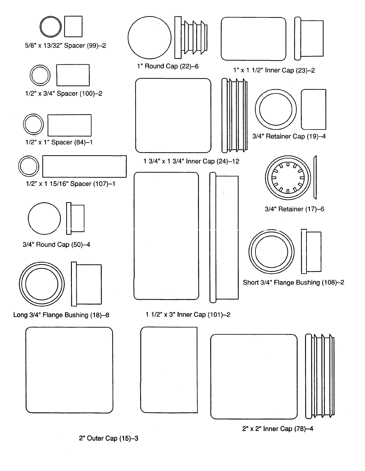
5/8"x 13/32"Spacer(99)-2
© I
1/2" x 3/4" Spacer (100)-2
©
1/2" x 1 15/16" Spacer (107)-1
3/4" Round Cap (50)-4
L..
Long 3/4" Flange Bushing (18)-8
1
1" Round Cap (22)-6
I
1" x 1 1/2" Inner Cap (23)-2
iII
3/4" Retainer Cap (19)-4
1 3/4" x I 3/4" Inner Cap (24)-12
3/4" Retainer (17)-6
Short 3/4" Flange Bushing (108)-2
1 1/2" x 3" Inner Cap (101)-2
k.
2" x 2" Inner Cap (78)-4
2" Outer Cap (15)-3
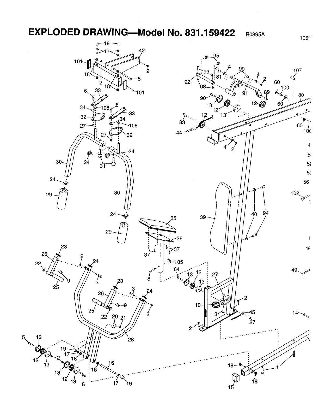
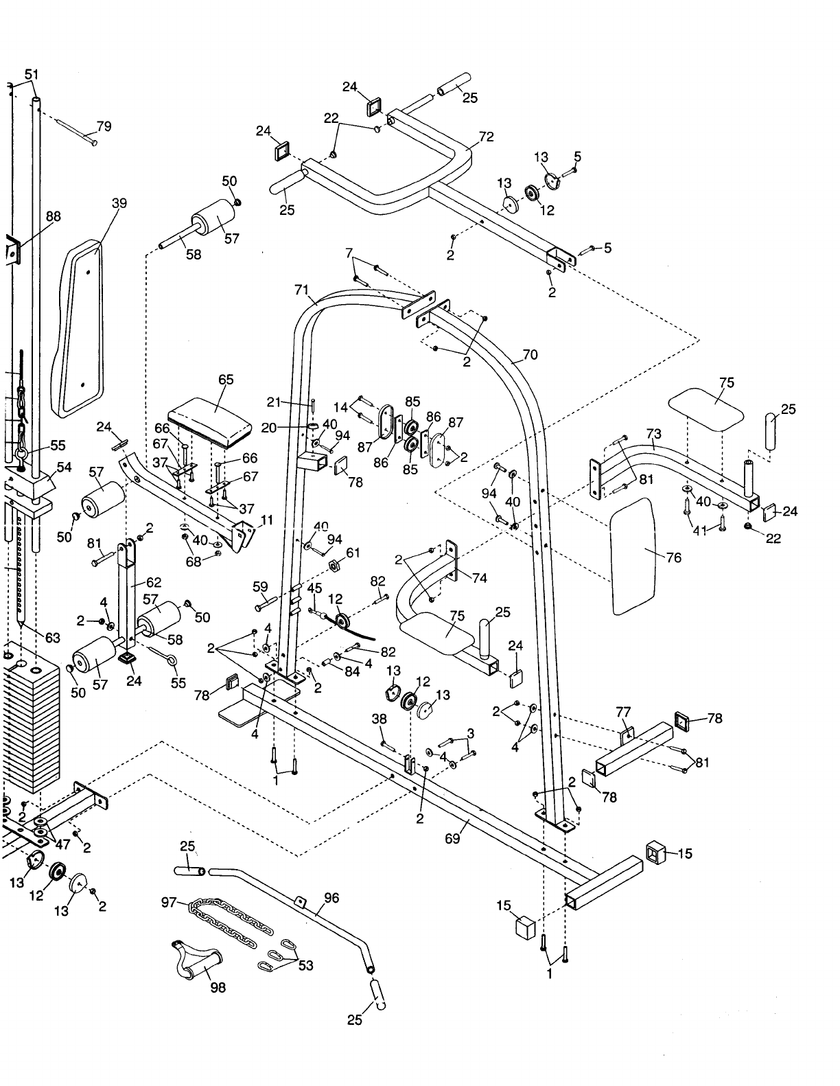
EXPLODED DRAWING....Mod,
7ol. _17_;_-'-_9-'_ el No. 831.159422
01
?
5_
56-
102
1
1
4_
51
25
72
2
13 5
12
70
3:
-24
22
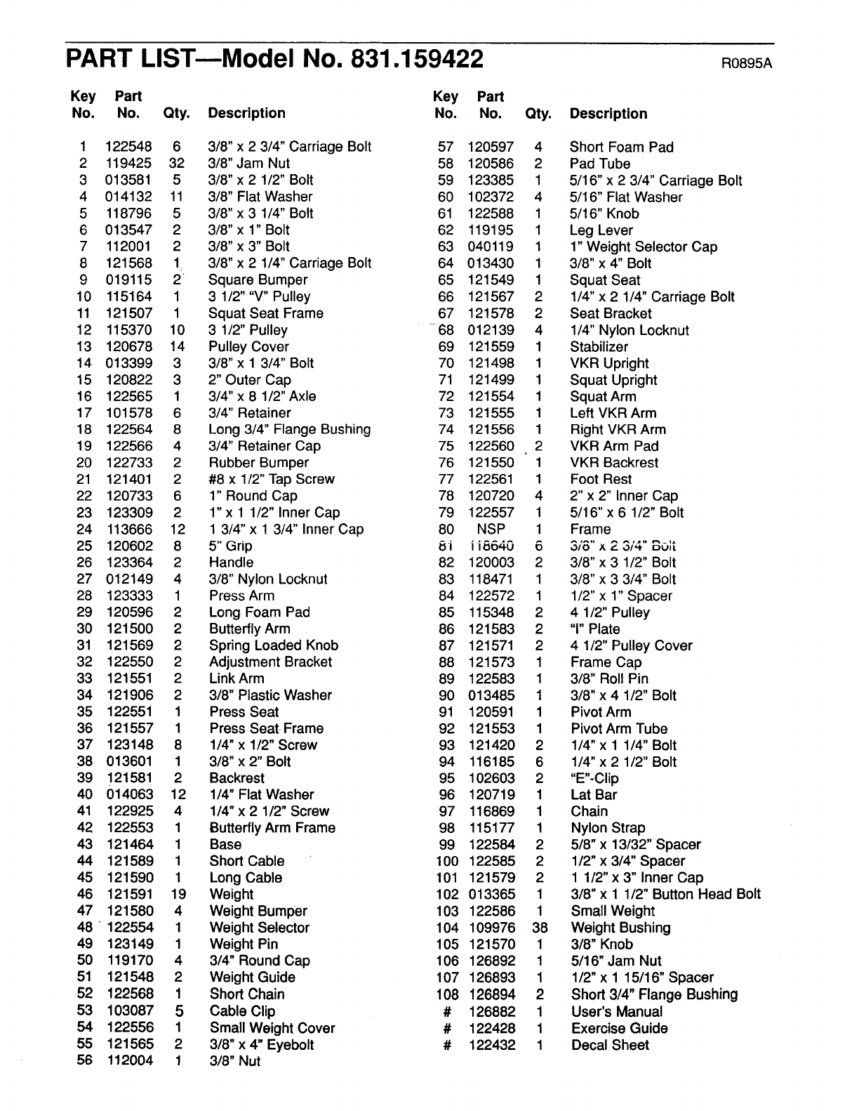
PART LISTmModel NO. 831.159422 Ro895A
Key Part
No. No, Qty. Description
Key Part
No. No. Qty. Description
1 122548 6 3/8" x 2 3/4" Carriage Bolt
2 119425 32 3/8" Jam Nut
3 013581 5 3/8" x 2 1/2" Bolt
4 014132 11 3/8" Flat Washer
5 118796 5 3/8" x 3 1/4, Bolt
6 013547 2 3/8" x 1" Bolt
7 112001 2 3/8" x 3" Bolt
8 121568 1 3/8" x 2 1/4" Carriage Bolt
9 019115 2 Square Bumper
10 115164 1 3 1/2""V" Pulley
11 121507 1 Squat Seat Frame
12 115370 10 3 1/2" Pulley
13 120678 14 Pulley Cover
14 013399 3 3/8" x 1 3/4" Bolt
15 120822 3 2" Outer Cap
16 122565 1 3/4" x 8 1/2"Axle
17 101578 6 3/4" Retainer
18 122564 8 Long 3/4" Flange Bushing
19 122566 4 3/4" Retainer Cap
20 122733 2 Rubber Bumper
21 121401 2 #8 x 1/2" Tap Screw
22 120733 6 1" Round Cap
23 123309 2 1" x 1 1/2" Inner Cap
24 113666 12 1 3/4" x 1 3/4" Inner Cap
25 120602 8 5" Grip
26 123364 2 Handle
27 012149 4 3/8" Nylon Locknut
28 123333 1 Press Arm
29 120596 2 Long Foam Pad
30 121500 2 Butterfly Arm
31 121569 2 Spring Loaded Knob
32 122550 2 Adjustment Bracket
33 121551 2 Link Arm
34 121906 2 3/8" Plastic Washer
35 122551 1 Press Seat
36 121557 1 Press Seat. Frame
37 123148 8 1/4" x 1/2" Screw
38 013601 1 3/8" x 2" Bolt
39 121581 2 Backrest
40 014063 12 1/4" Flat Washer
41 122925 4 1/4" x 2 1/2" Screw
42 122553 1 Butterfly Arm Frame
43 121464 1 Base
44 121589 1 Short Cable
45 121590 1 Long Cable
46 121591 19 Weight
47 121580 4 Weight Bumper
48 • 122554 1 Weight Selector
49 123149 1 Weight Pin
50 119170 4 3/4" Round Cap
51 121548 2 Weight Guide
52 122568 1 Short Chain
53 103087 5 Cable Clip
54 122556 1 Small Weight Cover
55 121565 2 3/8" x 4" Eyebolt
56 112004 1 3/8" Nut
57 120597 4 Short Foam Pad
58 120586 2 Pad Tube
59 123385 1 5/16" x 2 3/4" Carriage Bolt
60 102372 4 5/16" Flat Washer
61 122588 1 5/16" Knob
62 119195 1 Leg Lever
63 040119 1 1" Weight Selector Cap
64 013430 1 3/8" x 4" Bolt
65 121549 1 Squat Seat
66 121567 2 1/4" x 2 1/4" Carriage Bolt
67 121578 2 Seat Bracket
68 012139 4 1/4" Nylon Locknut
69 121559 1 Stabilizer
70 121498 1 VKR Upright
71 121499 1 Squat Upright
72 121554 1 Squat Arm
73 121555 1 Left VKR Arm
74 121556 1 Right VKR Arm
75 122560 2 VKR Arm Pad
76 121550 1 VKR Backrest
77 122561 1 Foot Rest
78 120720 4 2" x 2" Inner Cap
79 122557 1 5/16" x 6 1/2" Bolt
80 NSP 1 Frame
8i ii8640 6 3/8"x2 .........
OIH" DUIt
82 120003 2 3/8" x 3 1/2" Bolt
83 118471 1 3/8" x 3 3/4" Bolt
84 122572 1 1/2" x 1" Spacer
85 115348 2 4 1/2" Pulley
86 121583 2 "1" Plate
87 121571 2 4 1/2" Pulley Cover
88 121573 1 Frame Cap
89 122583 13/8" Roll Pin
90 013485 1 3/8" x 4 1/2" Bolt
91 120591 1 Pivot Arm
92 121553 1 Pivot Arm Tube
93 121420 2 1/4" x 1 1/4" Bolt
94 116185 6 1/4" x 2 1/2" Bolt
95 102603 2 "E"-Clip
96 120719 1 Lat Bar
97 116869 1 Chain
98 115177 1 Nylon Strap
99 122584 2 5/8" x 13/32" Spacer
100 122585 2 1/2" x 3/4" Spacer
101 121579 2 1 1/2" x 3" Inner Cap
102 013365 1 3/8" x 1 1/2" Button Head Bolt
103 122586 1 Small Weight
104 109976 38 Weight Bushing
105 121570 1 3/8" Knob
106 126892 1 5/16" Jam Nut
107 126893 1 1/2" x 1 15/16" Spacer
108 126894 2 Short 3/4" Flange Bushing
# 126882 1 User's Manual
# 122428 1 Exercise Guide
# 122432 1 Decal Sheet
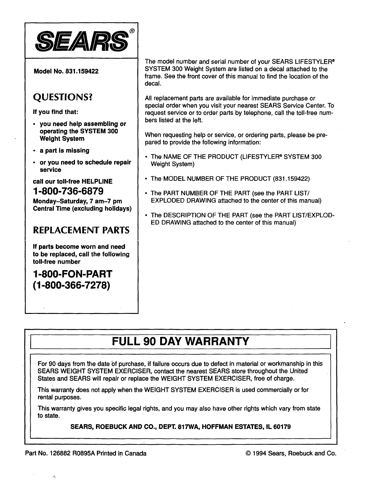
SE/A/ S'o
Model No. 831.159422
QUESTIONS?
If you find that:
you need help assembling or
operating the SYSTEM 300
Weight System
• a part is missing
•or you need to schedule repair
service
call our toll-free HELPLINE
1-800-736-6879
Monday-Saturday, 7 am-7 pm
Central Time (excluding holidays)
REPLACEMENT PARTS
If parts become worn and need
to be replaced, call the following
toll-free number
1-800-FON-PART
(1-800-366-7278)
The model number and serial number of your SEARS LIFESTYLER ®
SYSTEM 300 Weight System are listed on a decal attached to the
frame. See the front cover of this manual to find the location of the
decal.
All replacement parts are available for immediate purchase or
special order when you visit your nearest SEARS Service Center. To
request service or to order parts by telephone, call the toll-free num-
bers listed at the left.
When requesting help or service, or ordering parts, please be pre-
pared to provide the following information:
• The NAME OF THE PRODUCT (LIFESTYLER ® SYSTEM 300
Weight System)
•The MODEL NUMBER OF THE PRODUCT (831.159422)
• The PART NUMBER OF THE PART (see the PART LIST/
EXPLODED DRAWING attached to the center of this manual)
•The DESCRIPTION OF THE PART (see the PART LIST/EXPLOD-
ED DRAWING attached to the center of this manual)
I FULL 90 DAY WARRANTY I
For 90 days from the date bf purchase, if failure occurs due to defect in material or workmanship in this
SEARS WEIGHT SYSTEM EXERCISER, contact the nearest SEARS store throughout the United
States and SEARS will repair or replace the WEIGHT SYSTEM EXERCISER, free of charge.
This Warranty does not apply when the WEIGHT SYSTEM EXERCISER is used commercially or for
rental purposes.
This warranty gives you specific legal rights, and you may also have other rights which vary from state
to state.
SEARS, ROEBUCK AND CO., DEPT. 817WA, HOFFMAN ESTATES, IL 60179
Part No. 126882 R0895A Printed in Canada © 1994 Sears, Roebuck and Co.
