Liftmaster Mt5011 Owners Manual 01 10332M
2014-07-19
: Liftmaster Liftmaster-Mt5011-Owners-Manual liftmaster-mt5011-owners-manual liftmaster pdf
Open the PDF directly: View PDF ![]() .
.
Page Count: 24
- OWNER'S MANUAL
- TABLE OF CONTENTS
- OPERATOR SPECIFICATIONS
- OPERATOR DIMENSIONS
- PREPARATION
- INSTALLATION
- ADJUSTMENT
- POWER WIRING
- CONTROL STATION WIRING
- TESTING AND MAINTENANCE
- SCHEMATIC DIAGRAM FOR MT5011 - 1753
- WIRING DIAGRAM FOR MT5011 - 1753
- SCHEMATIC DIAGRAM FOR BMT5011 - 1754
- WIRING DIAGRAM FOR BMT5011 - 1754
- ELECTRICAL BOX
- REPAIR PARTS - ELECTRICAL BOX
- ILLUSTRATED PARTS
- REPAIR PARTS KITS
- CONTROL CONNECTION DIAGRAM

Serial #
(located on electrical box cover)
Installation Date
Wiring Type
C2 Wiring
FACTORY SET
See page 11 for
other wiring
configurations
2 YEAR WARRANTY
NOT FOR RESIDENTIAL USE
OO WW NN EE RR ’’ SS MM AA NN UU AA LL
MMOODDEELL MMTT
MMEEDDIIUUMM DDUUTTYY DDOOOORR OOPPEERRAATTOORR
Visit www.LiftMaster.com to locate a professional installing dealer in your area.
INTENDED FOR PROFESSIONAL INSTALLATION ONLY
A SAFETY DEVICE IS HIGHLY RECOMMENDED
2
TABLE OF CONTENTS
SPECIFICATIONS
Operator Dimensions . . . . . . . . . . . . . . . . . . . . . . . . . . . . . . . . . .3
Operator Specifications . . . . . . . . . . . . . . . . . . . . . . . . . . . . . . . .3
PREPARATION
Track Assembly . . . . . . . . . . . . . . . . . . . . . . . . . . . . . . . . . . . . . .4
Powerhead Attachment . . . . . . . . . . . . . . . . . . . . . . . . . . . . . . . . .4
Trolley Carriage/Chain Attachment . . . . . . . . . . . . . . . . . . . . . . . .4
INSTALLATION
Mount the Header Bracket . . . . . . . . . . . . . . . . . . . . . . . . . . . . . .5
Mount the Operator . . . . . . . . . . . . . . . . . . . . . . . . . . . . . . . . . . .5
Hang the Operator . . . . . . . . . . . . . . . . . . . . . . . . . . . . . . . . . . . .6
Straight Arm Attachment . . . . . . . . . . . . . . . . . . . . . . . . . . . . . . .6
Entrapment Protection Accessories . . . . . . . . . . . . . . . . . . . . . . .7
ADJUSTMENT
Limit Switch Adjustment . . . . . . . . . . . . . . . . . . . . . . . . . . . . . . .7
Emergency Disconnect System . . . . . . . . . . . . . . . . . . . . . . . . . .8
Brake Adjustment . . . . . . . . . . . . . . . . . . . . . . . . . . . . . . . . . . . . .9
Clutch Adjustment and Auxiliary Reversal System . . . . . . . . . . . .9
POWER WIRING
. . . . . . . . . . . . . . . . . . . . . . . . . . . . . . . . . .10
CONTROL STATION WIRING
Determine Wiring Type . . . . . . . . . . . . . . . . . . . . . . . . . . . . . . . .11
Special Control Wiring . . . . . . . . . . . . . . . . . . . . . . . . . . . . . . . .11
Mount Warning Notice . . . . . . . . . . . . . . . . . . . . . . . . . . . . . . . .11
Radio Controls . . . . . . . . . . . . . . . . . . . . . . . . . . . . . . . . . . . . . .12
Additional Access Control Equipment . . . . . . . . . . . . . . . . . . . . .12
External Interlock Switch . . . . . . . . . . . . . . . . . . . . . . . . . . . . . .12
TESTING AND MAINTENANCE
. . . . . . . . . . . . . . . . . . . . .13
DIAGRAMS
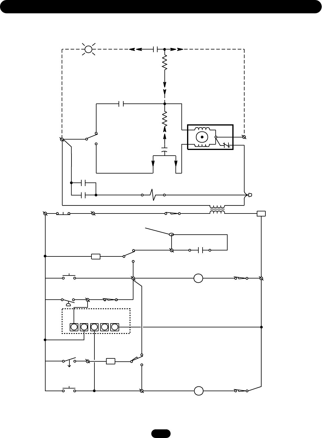
Schematic Diagram for MT5011 . . . . . . . . . . . . . . . . . . . . . . . . .14
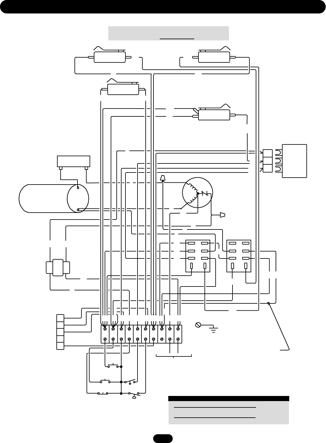
Wiring Diagram for MT5011 . . . . . . . . . . . . . . . . . . . . . . . . . . . .15
Schematic Diagram for BMT5011 . . . . . . . . . . . . . . . . . . . . . . .16
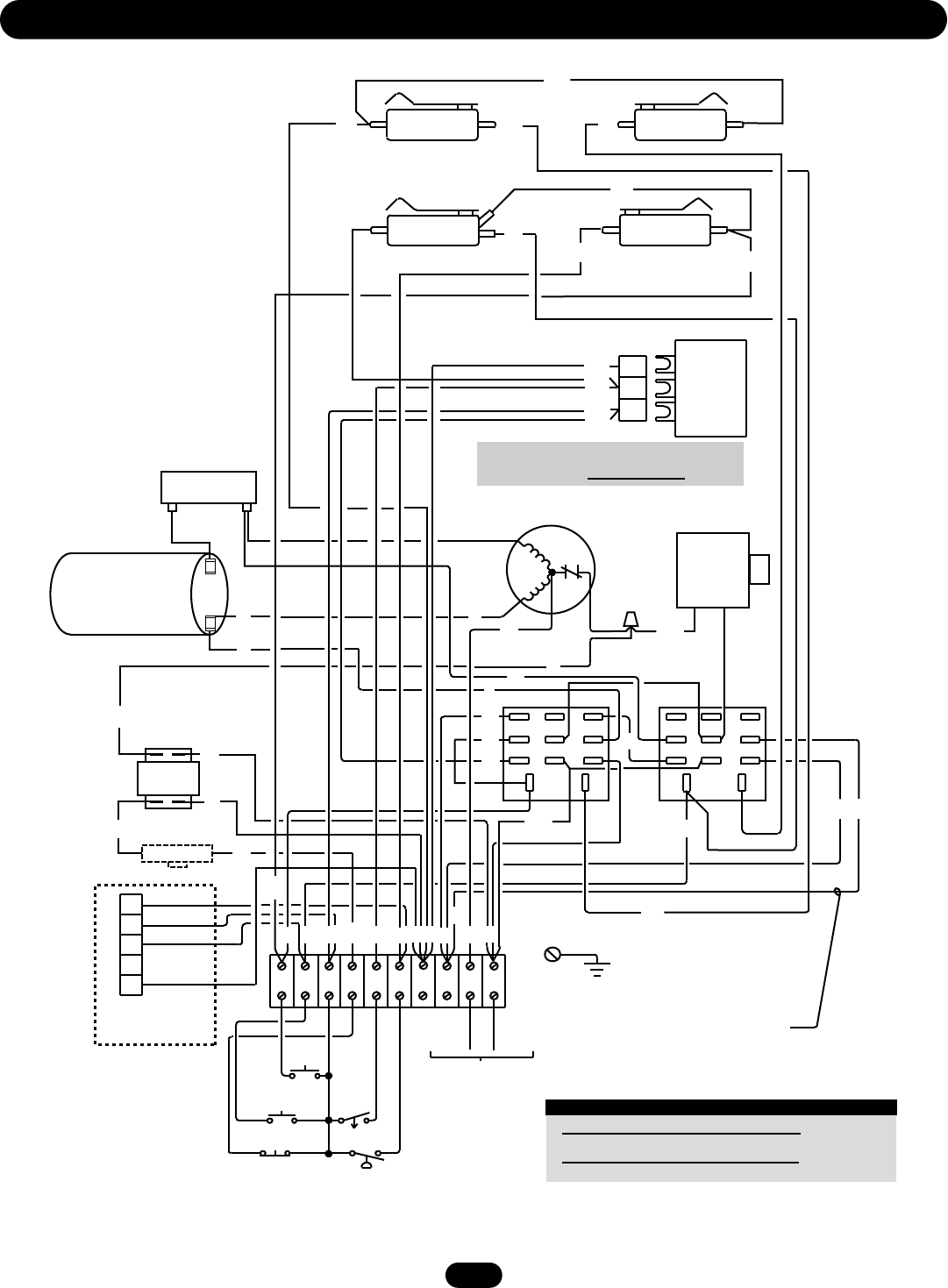
Wiring Diagram for BMT5011 . . . . . . . . . . . . . . . . . . . . . . . . . .17
REPAIR PARTS
Electrical Box . . . . . . . . . . . . . . . . . . . . . . . . . . . . . . . . . . . . .18-19
Repair Parts Kits . . . . . . . . . . . . . . . . . . . . . . . . . . . . . . . . . .20-21
OPERATOR NOTES
. . . . . . . . . . . . . . . . . . . . . . . . . . . . .22-23
CONTROL CONNECTION DIAGRAM
. . . . . . . . . . . . . . . .24
When you see these Safety Symbols and Signal Words on the
following pages, they will alert you to the possibility of serious
injury or death if you do not comply with the warnings that
accompany them. The hazard may come from something
mechanical or from electric shock. Read the warnings carefully.
When you see this Signal Word on the following pages, it will
alert you to the possibility of damage to your door and/or the
door operator if you do not comply with the cautionary
statements that accompany it. Read them carefully.
Mechanical
Electrical
ATTENTION
AVERTISSEMENT AVERTISSEMENT
AVERTISSEMENT
WARNINGWARNING
CAUTION
WARNING
WARNING
PRECAUCIÓN ADVERTENCIA
ADVERTENCIAADVERTENCIA
ATTENTION
AVERTISSEMENT AVERTISSEMENT
AVERTISSEMENT
WARNING
CAUTION
WARNINGWARNING
WARNING
PRECAUCIÓN ADVERTENCIA
ADVERTENCIAADVERTENCIA
ATTENTION
AVERTISSEMENT AVERTISSEMENT
AVERTISSEMENT
WARNING
CAUTIONCAUTION
WARNING
WARNING
PRECAUCIÓN ADVERTENCIA
ADVERTENCIAADVERTENCIA
IMPORTANT NOTES:
• BEFORE attempting to install, operate or maintain the operator,
you must read and fully understand this manual and follow all
safety instructions.
• DO NOT attempt installation, repair or service of your
commercial door and gate operator unless you are an
Authorized Service Technician.
3
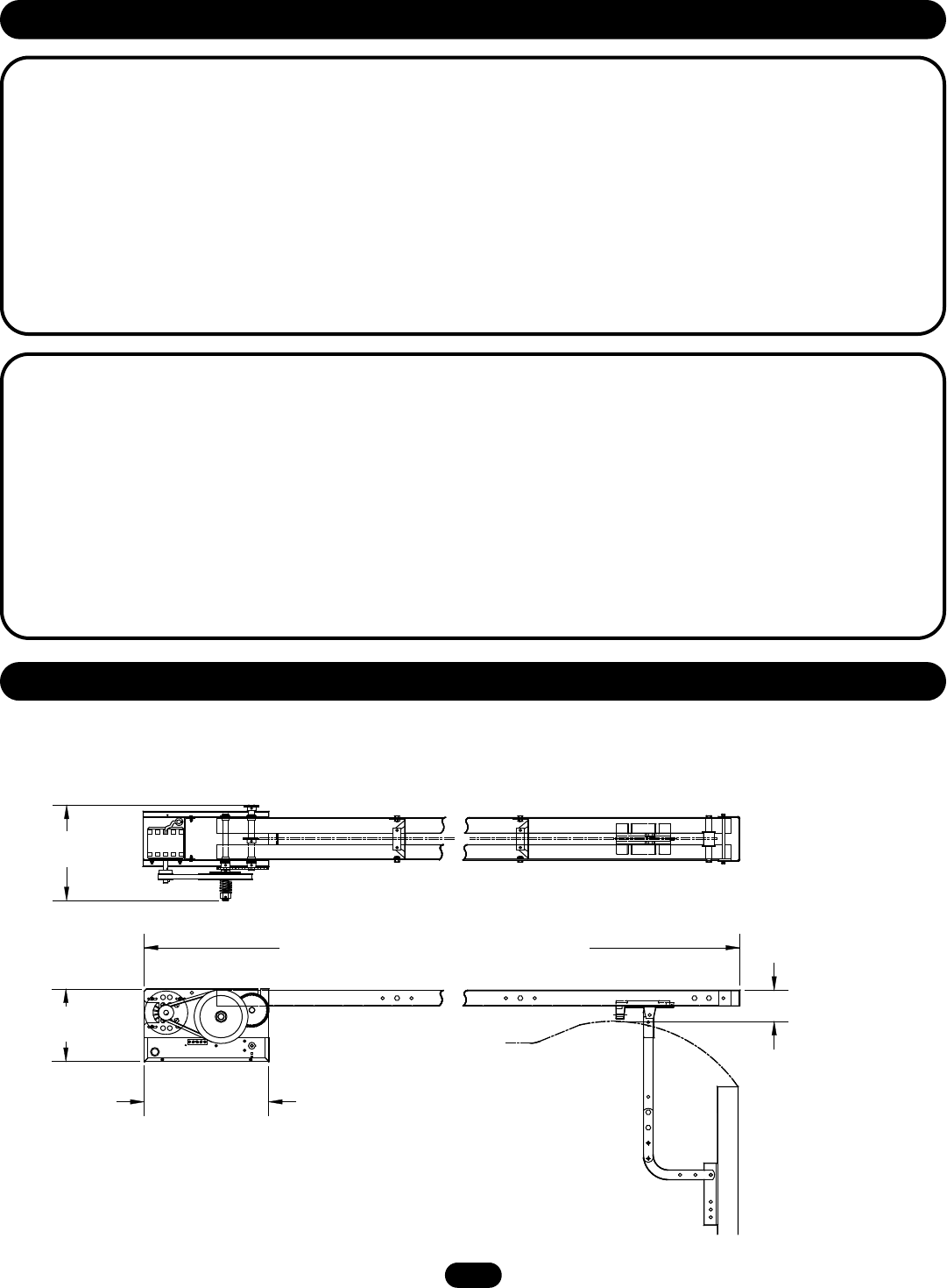
WEIGHTS AND DIMENSIONS
HANGING WEIGHT:80-110 LBS. (36.29-49.9 kg)
9-1/2"
(24.13 cm)
16-3/16"
(41.12 cm)
4"
(10.16 cm)
12-1/2"
(31.75 cm)
OPERATOR SPECIFICATIONS
SAFETY
DISCONNECT: .............................Quick disconnect door arm for
emergency manual door
operation.
SENSING DEVICE: ......................Accepts photo electric controls
such as CPS, or an electric / pneumatic sensing edge can be
attached to the bottom edge of door.
A sensing device is strongly recommended for all commercial
operator installations. Required when the 3-button control
station is out of sight of door or any other control (automatic or
manual) is used.
MOTOR
TYPE: . . . . . . . . . . . . . . . . . . . . . . . . . . . . . . . .Intermittent duty
HORSEPOWER: . . . . . . . . . . . . . . . . . . . . . . . . .1/2 Horsepower
SPEED: . . . . . . . . . . . . . . . . . . . . . . . . . . . . . . . . . . .1000 RPM
VOLTAGE: . . . . . . . . .115V, 1 Phase, 60Hz 230V, 1 Phase, 50Hz
CURRENT: . . . . . . . . . . . . . . . . . . . . . . . . .See motor nameplate
ELECTRICAL
TRANSFORMER: . . . . . . . . . . . . . . . . . . . . . . . . . . . . . . . .24Vac
CONTROL STATION: . . . . . . . . . . .NEMA 1 three button station.
OPEN/CLOSE/STOP
WIRING TYPE: . . . . . . . . . . . . . . . . . . . . .C2 (Factory Shipped)
Momentary contact to OPEN & STOP, constant pressure to
CLOSE, plus wiring for sensing device to reverse. See page 11
for control wiring options.
LIMIT ADJUST: . . . . . . . . . . . . . .Linear driven, fully adjustable
screw type cams.
MECHANICAL
DRIVE REDUCTION: . . . . . . . .Primary: Heavy duty (4L) V-Belt.
Secondary: #48 chain/sprocket. Output: #48 chain
OUTPUT SHAFT SPEED: . . . . . . . . . . . . . . . . . . . . . .108 R.P.M.
DOOR SPEED: . . . . . . . . .Approximately 9" (22.86 cm) per sec.
depending on door
BRAKE (Optional): . . . . . . . . . . . .Solenoid actuated disc brake
BEARINGS: . . . . . . . .IronCopper sintered and oil impregnated.
OPERATOR DIMENSIONS
Door Height Plus 4 feet (1.22 m) (minimum)
Highest Point of Door Travel
4
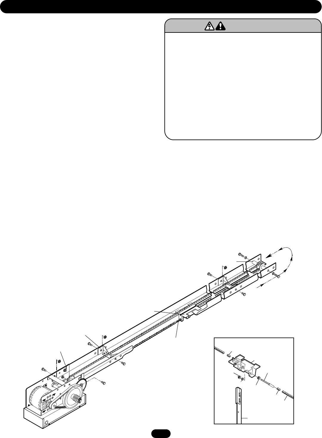
TROLLEY CARRIAGE / CHAIN ATTACHMENT
1. Attach the take-up bolt to the trolley carriage using
3/8-16" hex nuts and lock washer, as shown below.
2. Using one of the master links, attach the chain to the other
end of the trolley carriage. Reel the chain around the front idler
shaft, over the spacer brackets, back to the drive shaft
sprocket, and then to the take-up bolt on the carriage.
3. Using the other master link, attach the chain to the take-up
bolt and tighten to the desired chain tension.
Chain Tension: With trolley positioned at either end of the track, a
properly adjusted chain will sag about 3" (7.62 cm) at the
mid-point. If necessary, remove links from the chain to achieve
proper adjustment.
TRACK ASSEMBLY
1. Using the 3/8"-16 x 3/4" bolts and flange hex nuts provided,
assemble the operator track by installing and tightening the
track spacer brackets. Position the spacers evenly over the
length of the track. NOTE: The nylon pad on the spacer
bracket should face up.
2. Using (2) 3/8"-16 x 1" bolts and lock washers, install the front
idler assembly to the second set of holes of one end of the
track. Refer to the illustration below.
3. Slide the trolley carriage onto the track so that the take-up bolt
will be toward the operator.
POWERHEAD ATTACHMENT
1. Position the track assembly on the frame of the powerhead so
that the motor side of operator is in back (away from door).
2. Loosely install two 3/8"-16 x 3/4" bolts and nuts in third hole
from the end of the track.
3. Align the track so that the bolts inserted in step 2 line up with
the L-Slots in the frame.
4. Connect the track to the powerhead by fastening two
3/8"-16 x 3/4" bolts and nuts through the frame and the end
holes in track. Tighten all four bolts to secure the track to the
powerhead.
PREPARATION
To prevent possible SERIOUS INJURY or DEATH:
• DO NOT connect electric power until instructed to do so.
• If the door lock needs to remain functional, install an
interlock switch.
• ALWAYS call a trained professional door serviceman if door
binds, sticks or is out of balance. An unbalanced door may
not reverse when required.
• NEVER try to loosen, move or adjust doors, door springs,
cables, pulleys, brackets or their hardware, ALL of which are
under extreme tension and can cause SERIOUS personal
INJURY.
• Disable ALL locks and remove ALL ropes connected to door
BEFORE installing and operating door operator to avoid
entanglement.
ATTENTION
AVERTISSEMENT AVERTISSEMENT
AVERTISSEMENT
WARNING
CAUTION
WARNING
WARNINGWARNING
PRECAUCIÓN ADVERTENCIA
ADVERTENCIAADVERTENCIA
L-Slot
Spacer Bracket
(Mounted Nylon Pad Side Up)
Trolley Carriage
Take-Up Bolt
Front Idler Assembly
Master Link
Trolley Carriage
Take-Up Bolt
Hex Nut
Hex Nut
Master Link
Roller Chain
Straight Arm
Lockwasher
Trolley Assembly
Reel Chain
Around Idler and
Over Spacer Brackets
5
IMPORTANT NOTE: Before the operator is installed, be sure the door has been properly aligned and is working smoothly. Although
each installation will vary due to particular building characteristics, refer to the following general procedures to install the operator.
MOUNT HEADER BRACKET
The trolley operator is generally mounted over the center of the
door. However, off center mounting may be required due to
interfering structures or location of door stile / top section
support. In such cases, the operator may be mounted up to 24"
(60.96 cm) off center on torsion spring doors. Extension springs
require center mounting.
1. Locate the center of the door and mark a line on the wall
directly above the door. Extend this line up the wall.
2. Determine the highest point of door travel. Slowly raise the
door and observe the action of the top section. When the top
section reaches its highest point, use a level and project a line
from this point to the center line the of the door.
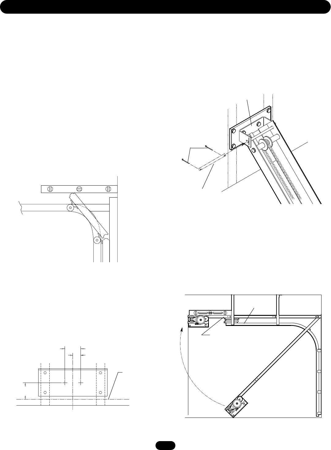
MOUNT OPERATOR
1. Allowing the motor to rest on the floor, raise the front end of
the track assembly to the front header bracket and fasten
using the 3/8" dia. x 6.40" long pivot shaft and cotterpins
provided.
3. Using the projected lines for location, mount a suitable wood
block or length of angle iron to the wall above the door
opening. Refer to the illustration below. This will provide a
mounting pad for the front header bracket of the operator. If
necessary reinforce the wall with suitable mounting brackets
to ensure adequate support of mounting pad. Using suitable
hardware, mount the (U-shaped) front header bracket to the
pad.
Header Bracket Drill Pattern
2. Swing the operator to a horizontal position above the guide
rails and temporarily secure with a suitable rope, chain, or
support from the floor. Now open garage door slowly, being
careful not to dislodge the temporary support. Using the door
as a support, place a level against the rail and shim the
operator until it is horizontal. Make sure that the operator is
aligned with the center line of the door.
Operator Alignment
Using the door as support, shim
operator to a horizontal position.
Guide
Rails
3.5"
(8.89 cm) 1.75"
(4.45 cm)
4" (10.16 cm)
Min.
INSTALLATION
High Rise Point
Projection Line
Vertical Center Line of Door
Header WallCarpenter’s
Level
Door Travel
Projection
High Point
of Travel
Header Bracket
Cotterpins
Pivot Shaft
6
INSTALLATION
To avoid possible SERIOUS INJURY from a falling operator,
fasten it SECURELY to structural supports of the garage.
Concrete anchors MUST be used if installing ANY brackets
into masonry.
ATTENTION
AVERTISSEMENT AVERTISSEMENT
AVERTISSEMENT
WARNINGWARNING
CAUTION
WARNING
WARNING
PRECAUCIÓN ADVERTENCIA
ADVERTENCIAADVERTENCIA
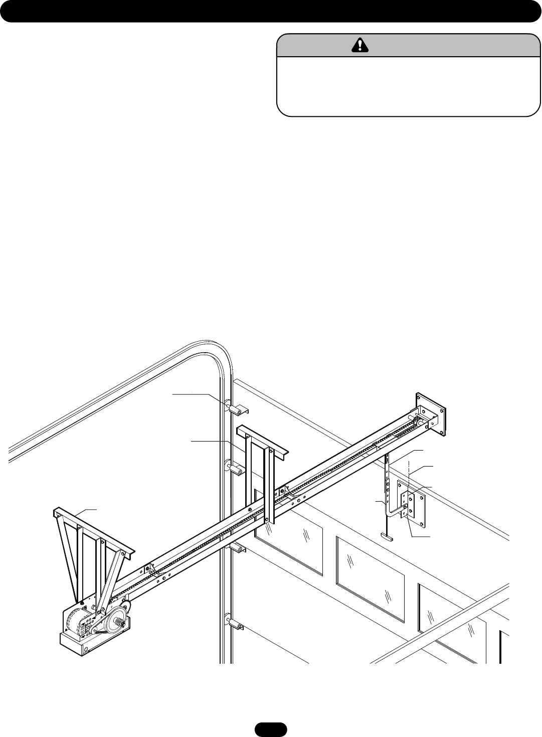
HANG THE OPERATOR
1. The illustration below shows a typical method of hanging the
operator from the ceiling. Each installation may vary, but in all
cases side braces should be used for additional strength.
2. For mounting of the support brace(s) to the powerhead. Four
holes (clearance up to 3/8" bolts) are located on each side of
frame.
3. Check to make sure the track is centered over the door (or in
line with the header bracket if the bracket is not centered above
the door).
NOTE: If the operator is longer than 15' (4.57 m) use of a
mid-span support is recommended.
STRAIGHT ARM ATTACHMENT
1. Fully close the door and move the trolley slider to within 2"
(5.08 cm) of the front idler.
2. Latch the straight door arm to the fixed roll pin in the trolley
carriage. Make sure the open side of notch on the arm faces
the doorway.
3. Attach the door bracket to the door arm using the 3/8"-16 x 1"
bolt and nylon locking nut provided. Leave the nut and bolt
loose enough to allow the two pieces to pivot freely.
4. Using 3/8" hardware provided, bolt the curved door arm to the
straight arm, aligning the mounting holes in such a way that
the door bracket pivot bolt will be in line with the top rollers on
the door.
5. Position the door bracket to the center line on the door. Using
suitable hardware, attach the door bracket to the door. Many
installations, except solid wood doors, will require additional
support for the door. Refer to the illustration below.
NOTE: At this time, ensure all bolts and lag screws are properly
secured.
Powerhead Support Brace
Mid-Span
Support Brace
Top
Roller
Curved
Door Arm
Straight Arm
Center Line of Door
Door Bracket
Pivot Bolt
7
ENTRAPMENT PROTECTION ACCESSORIES
(OPTIONAL)
SENSING EDGES
All types of sensing edges with an isolated normally open (N.O.)
output are compatible with your operator. This includes
pneumatic and electric edges. If your door does not have a
bottom sensing edge and you wish to purchase one, contact the
supplier of your operator.
If not pre-installed by the door manufacturer, mount the sensing
edge on the door according to the instructions provided with the
edge. The sensing edge may be electrically connected by either
coiled cord or take-up reel. Refer to the steps below.
Important Notes:
a) Proceed with Limit Switch Adjustments before making any
sensing edge wiring connections to operator as described
below.
b) Electrician must hardwire the junction box to the operator
electrical box in accordance with local codes.
TAKE-UP REEL: Take-up reel should be installed 12" (30.48 cm)
above the top of the door.
COIL CORD: Connect operator end of coil cord to junction box
(not provided) fastened to the wall approximately halfway up the
door opening.
INSTALLATION
To reduce the risk of SEVERE INJURY or DEATH, ALWAYS
install reversing sensors when the 3-button control station is
out of sight of door or ANY other control (automatic or manual)
is used. Reversing devices are recommended for ALL
installations.
ATTENTION
AVERTISSEMENT AVERTISSEMENT
AVERTISSEMENT
WARNINGWARNING
CAUTION
WARNING
WARNING
PRECAUCIÓN ADVERTENCIA
ADVERTENCIAADVERTENCIA
ADJUSTMENT
To avoid SERIOUS PERSONAL INJURY or DEATH from
electrocution, disconnect electric power BEFORE manually
moving limit nuts.
ATTENTION
AVERTISSEMENT AVERTISSEMENT
AVERTISSEMENT
WARNING
CAUTION
WARNING
WARNINGWARNING
PRECAUCIÓN ADVERTENCIA
ADVERTENCIAADVERTENCIA
Sensor for Auxiliary Reversing System
OPEN Limit Switch
Retaining Plate
CLOSE Limit Switch
AUX. OPEN
Limit Switch
SAFETY
(Aux. Close) Limit Switch
LIMIT SWITCH ADJUSTMENT
NOTE: Make sure the limit nuts are positioned between the limit
switches before proceeding with adjustments.
1. Depress retaining plate to allow nut to spin freely. After
adjustment, release plate and move nut back and forth to
ensure it is fully seated in slot.
2. To increase door travel, spin nut away from limit switch. To
decrease door travel, spin limit nut toward limit switch.
3. Adjust open limit nut so that door will stop in open position
with the bottom of the door even with top of door opening.
4. Repeat steps 1 and 2 for close cycle. Adjust close limit nut so
that the limit switch is engaged as door fully seats at the floor.
8
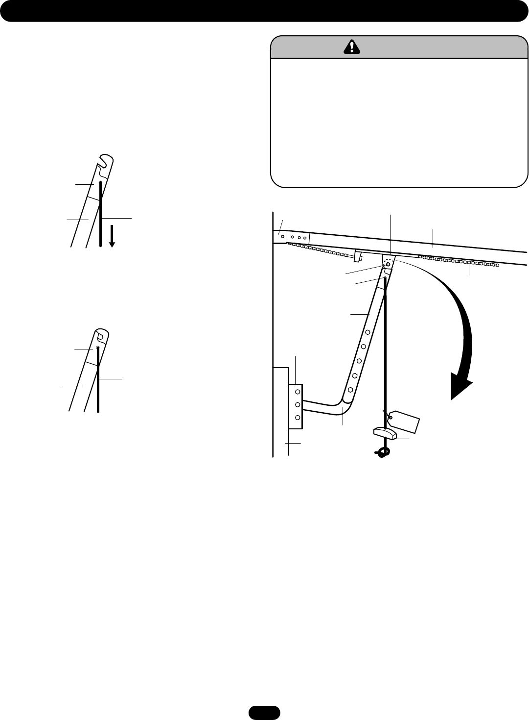
EMERGENCY DISCONNECT SYSTEM
ADJUSTMENT
NO EC
I
T
To prevent possible SERIOUS INJURY or DEATH from a falling
door or arm:
• DO NOT stand under the door arm when pulling the
emergency release.
• If possible, use emergency release handle to disengage trolley
ONLY when door is CLOSED. Weak or broken springs or
unbalanced door could result in an open door falling rapidly
and/or unexpectedly.
• NEVER use emergency release handle unless doorway is clear
of persons and obstructions.
ATTENTION
AVERTISSEMENT AVERTISSEMENT
AVERTISSEMENT
WARNINGWARNING
CAUTION
WARNING
WARNING
PRECAUCIÓN ADVERTENCIA
ADVERTENCIAADVERTENCIA
Header
Bracket Trolley
Track
Chain
Clevis Pin
Emergency
Disconnect
Straight
Door Arm
Assembly
Door
Bracket
Curved
Door Arm
Door Emergency
Release Handle
Emergency
Disconnect
Emergency
Disconnect
Door Arm
Door Arm
Pull emergency release
handle straight down.
Emergency disconnect
will open.
Lift free end of door arm
to trolley. Pull emergency
handle to allow arm to
engage roll pin. Release
handle. Emergency
disconnect will close.
TO DISCONNECT DOOR FROM OPERATOR
The door should be in the fully closed position if possible. Pull
down on the emergency release handle (so that the trololey
release arm snaps into a vertical position) and lift the door
manually. The lockout feature prevents tthe troley from
reconnecting automatically, andd the door can be raised and
loweredd manually as often as necessary.
TO RECONNECT DOOR ARM TO TROLLEY
Pull the emergency release handle toward the operator at an
angle so that the trolley release arm is horizontal. The trolley will
reconnect on the next UP or DOWN operation, either manually or
by using the door control or remote.
9
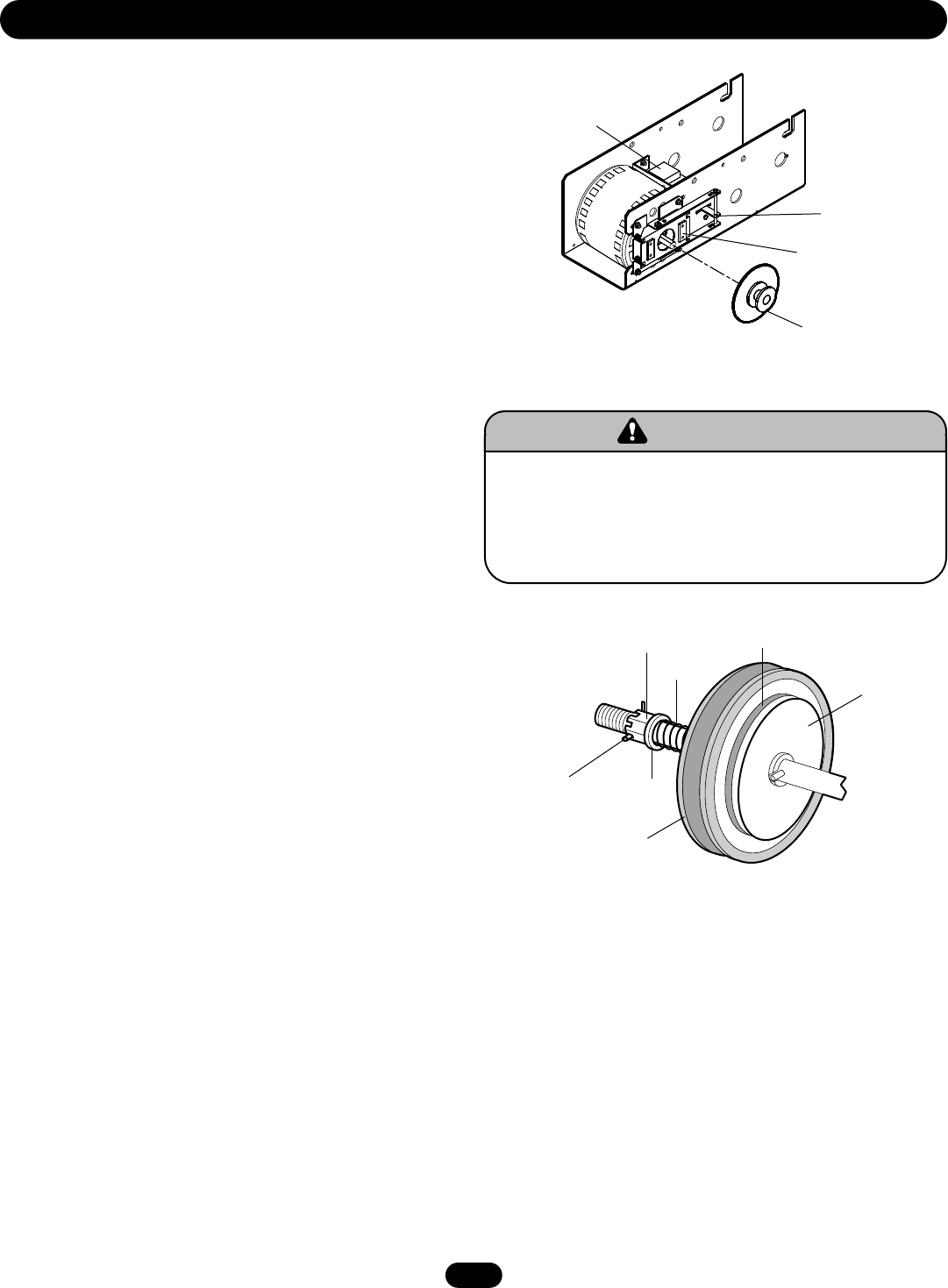
CLUTCH ADJUSTMENT AND
AUXILIARY REVERSAL SYSTEM
The Auxiliary Reversal System is designed to protect the door
and motorized operator. It is NOT a substitute for a safety sensing
device. The Auxiliary Reversal System works in tandem with the
adjustable clutch to detect if a closing door runs into or comes
across an obstruction. If an obstruction is met and causes the
clutch to slip, the Auxiliary Reversal System will return the door
to the full open position when closing or stops the door when
opening.
1. Remove cotterpin from nut on the clutch shaft.
2. Back off clutch nut until there is very little tension on the
clutch spring.
3. Tighten clutch nut gradually until there is just enough tension
to permit the operator to move the door smoothly but to allow
the clutch to slip if the door is obstructed. When the clutch is
properly adjusted, it should generally be possible to stop the
door by hand during travel.
4. Reinstall cotterpin.
ADJUSTMENT
To prevent possible SERIOUS INJURY or DEATH, install
reversing sensors when the 3-button control station is out of
sight of the door or ANY other control (automatic or manual) is
used. Reversing devices are recommended for ALL
installations.
ATTENTION
AVERTISSEMENT AVERTISSEMENT
AVERTISSEMENT
WARNINGWARNING
CAUTION
WARNING
WARNING
PRECAUCIÓN ADVERTENCIA
ADVERTENCIAADVERTENCIA
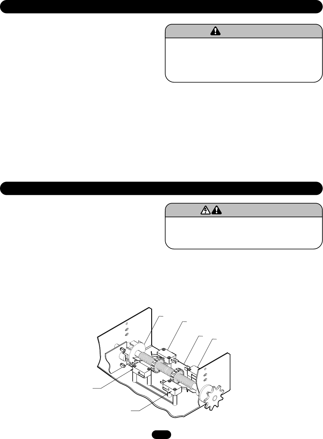
BRAKE ADJUSTMENT
A solenoid brake is an optional modification. If provided, the
brake is adjusted at the factory and should not need additional
adjustment for the the life of the friction pad.
Replace friction pads when necessary. Refer to the illustration for
identification of components for the solenoid type brake system.
Solenoid
Release Lever
Friction Pads
Pulley
Clutch Pulley
Cotterpin Washer
Adjusting Nut
Spring
Clutch Pad
Clutch Plate
10
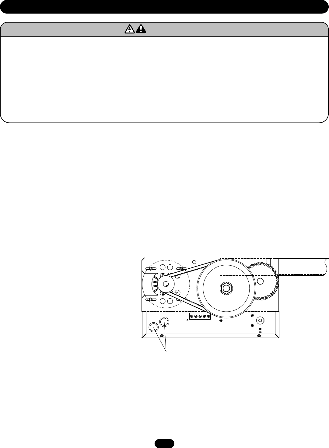
POWER WIRING CONNECTIONS
Remove the cover from the electrical enclosure. Inside this
enclosure you will find the wiring diagram(s) for your unit. Refer
to the diagram (glued on the inside of the cover) for all
connections described below. If this diagram is missing, call the
number on the back of this manual.
1. Be sure that the power supply is of the correct voltage, phase,
frequency, and amperage to supply the operator. Refer to the
operator nameplate on the cover.
2. Using the 1-1/16" dia conduit access hole as shown below,
bring supply lines to the operator and connect wires to the
terminals indicated on the WIRING CONNECTIONS DIAGRAM.
Do not turn power on until you have finished making all power
and control wiring connections and have completed the limit
switch adjustment procedure.
POWER WIRING
To reduce the risk of SEVERE INJURY or DEATH:
• ANY maintenance to the operator or in the area near the
operator MUST NOT be performed until disconnecting the
electrical power and locking-out the power via the operator
power switch. Upon completion of maintenance the area MUST
be cleared and secured, at that time the unit may be returned
to service.
• Disconnect power at the fuse box BEFORE proceeding.
Operator MUST be properly grounded and connected in
accordance with local electrical codes. The operator should be
on a separate fused line of adequate capacity.
• ALL electrical connections MUST be made by a qualified
individual.
• Do not install ANY wiring or attempt to run the operator
without consulting the wiring diagram. We recommend that
you install an optional reversing edge BEFORE proceeding with
the control station installation.
• ALL power wiring should be on a dedicated circuit and well
protected. The location of the power disconnect should be
visible and clearly labeled.
• ALL power and control wiring MUST be run in separate
conduit.
ATTENTION
AVERTISSEMENT AVERTISSEMENT
AVERTISSEMENT
WARNING
CAUTION
WARNING
WARNINGWARNING
PRECAUCIÓN ADVERTENCIA
ADVERTENCIAADVERTENCIA
Two 7/8" and 1-1/16" Knockouts
(1 each side) for Control and Power Wiring
11
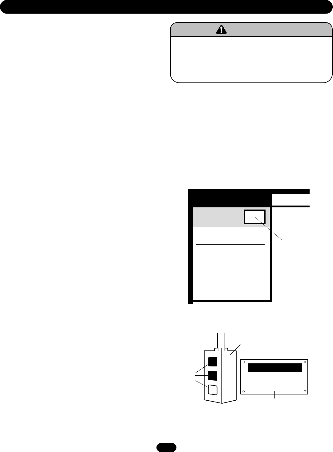
DETERMINE WIRING TYPE
Refer to the wiring diagram located on the inside cover the
electrical box to determine the type of control wiring.
Standard C2 or B2 Wiring
Standard operators are shipped from the factory with jumper set
for C2 wiring, which requires constant pressure on button to
close the door. If momentary contact on close direction is desired
(B2 wiring) you must include an entrapment protection device.
Constant pressure on close (C2 wiring)
In the electrical enclosure, a RED wire was placed on terminal
block #12. With this setting, the operator will require constant
pressure on close control in order to keep door moving in the
close direction.
Momentary contact on close (B2 wiring)
Move RED wire from terminal block #12 to terminal #2. The
operator will require only momentary contact to close the door.
WI
This Operator has
Control Wiring.
SPECIAL CONTROL
WIRING DIAGRAM
Note: Supplemental Wiring Diagrams are
to be used in addition to 1742-1.
Replacement Wiring Diagram is to be used
in place of 1742-1
REPLACEMENT WIRING DIAGRAM
SUPPLEMENTAL WIRING DIAGRAM(S)
MOUNT WARNING NOTICE
LOCATING THE CONTROL STATION
All operators are provided with some type of control station.
Generally a three button station (OPEN/CLOSE/STOP) is provided.
A two-position key switch or control station (OPEN/CLOSE) may
be added or substituted when requested at the time of order.
Mount the control station near the door.
IMPORTANT: Mount WARNING NOTICE beside or below the push
button station.Mount control station(s) within line of sight of
door(s).
WARNINGWARNING
TO PREVENT ENTRAPMENT
DO NOT START DOOR DOWNWARD
UNLESS DOORWAY IS CLEAR
OPENOPEN
CLOSECLOSE
STOP
WARNIN G
Wiring Diagram label on inside cover of electrical box
Wiring Type
CONTROL STATION WIRING
To prevent possible SERIOUS INJURY or DEATH, install
reversing sensors when the 3-button control station is out of
sight of the door or ANY other control (automatic or manual) is
used. Reversing devices are recommended for ALL
installations.
ATTENTION
AVERTISSEMENT AVERTISSEMENT
AVERTISSEMENT
WARNINGWARNING
CAUTION
WARNING
WARNING
PRECAUCIÓN ADVERTENCIA
ADVERTENCIAADVERTENCIA
SPECIAL CONTROL WIRING
If your operator was shipped from the factory with
non-standard control wiring or with optional accessories that
require addition instructions, refer to the wiring diagram(s)
indicated in the special control wiring data box. When a
replacement wiring diagram is present, wiring diagrams in this
manual will not apply. Refer only to the replacement wiring
diagram for all connections.
Standard
Control Station
WARNING Notice
Push
Buttons

12
CONTROL STATION WIRING
To prevent possible SERIOUS INJURY or DEATH, install
reversing sensors when the 3-button control station is out of
sight of the door or ANY other control (automatic or manual) is
used. Reversing devices are recommended for ALL
installations.
ATTENTION
AVERTISSEMENT AVERTISSEMENT
AVERTISSEMENT
WARNINGWARNING
CAUTION
WARNING
WARNING
PRECAUCIÓN ADVERTENCIA
ADVERTENCIAADVERTENCIA
RADIO CONTROLS
On all models with type B2 control wiring, a terminal bracket
marked R1 R2 R3 is located on the outside of the electrical
enclosure. All standard radio control receivers (single channel
residential type) may be mounted to this bracket. The operator
will then open a fully closed door, close a fully open door, and
reverse a closing door from the radio transmitter. However, for
complete door control from a transmitter, a commercial
three-channel radio set (with connections for OPEN/CLOSE/STOP)
is recommended.
ADDITIONAL ACCESS CONTROL EQUIPMENT
Locate any additional access control equipment as desired (but
so that the door will be in clear sight of the person operating the
equipment), and connect to the terminal block in the electrical
enclosure as shown on the FIELD WIRING CONNECTIONS
diagram. Any control with a normally (N.O.) isolated output
contact may be connected in parallel with the OPEN button. More
than one device may be connected in this manner. Use 16 gauge
wire or larger for all controls. Do not use the control circuit
transformer (24Vac) in the operator to power any access control
equipment other than a standard residential type radio receiver.
EXTERNAL INTERLOCK SWITCH
The operator has a terminal connection for an external interlock
switch. This switch must be a normally closed (N.C.) two-wire
device with a contact rating of at least 3 amps @ 24Vac. When
such a switch is connected as shown on the FIELD WIRING
CONNECTIONS diagram, the control circuit will be disabled when
the switch is actuated, thereby preventing electrical operation of
the door from the control devices.
13
Turn on power. Test all controls and safety devices to make sure
they are working properly. It will be necessary to refer back to
page 7 for fine adjustment of the limit switches.
IMPORTANT NOTES:
• Do not leave operator power on unless all safety and
entrapment protection devices have been tested and are
working properly.
• Be sure you have read and understand all Safety Instructions
included in this manual.
• Be sure the owner or person(s) responsible for operation of
the door have read and understand the Safety Instructions,
know how to electrically operate the door in a safe manner,
and know how to use the manual disconnect operation of the
door operating system.
TESTING AND MAINTENANCE
To avoid SERIOUS PERSONAL INJURY or DEATH from
electrocution, disconnect ALL electric power BEFORE
performing ANY maintenance.
ATTENTION
AVERTISSEMENT AVERTISSEMENT
AVERTISSEMENT
WARNING
CAUTION
WARNING
WARNINGWARNING
PRECAUCIÓN ADVERTENCIA
ADVERTENCIAADVERTENCIA
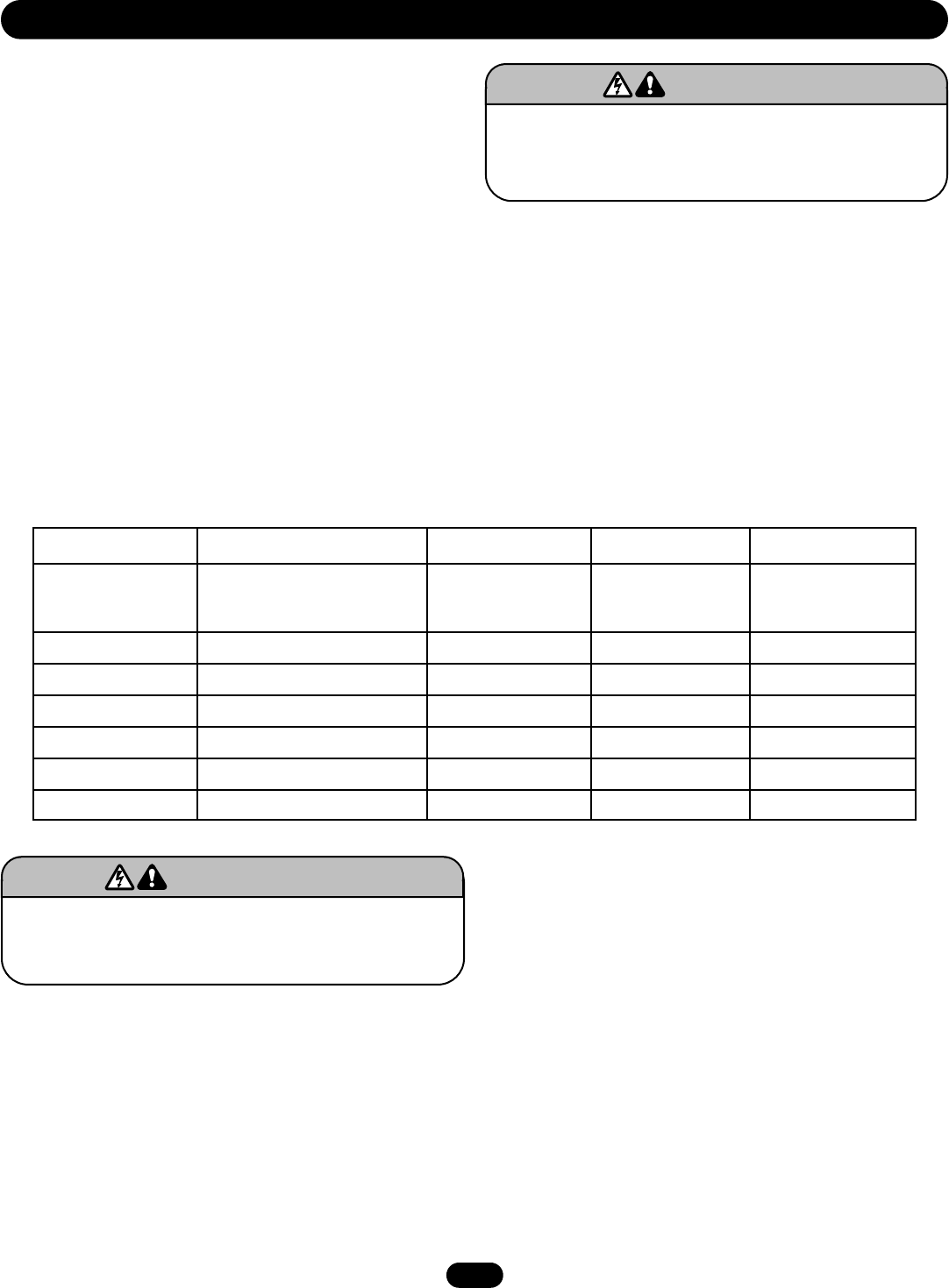
Check at the intervals listed in the following chart:
HOW TO ORDER REPAIR PARTS
OUR LARGE SERVICE ORGANIZATION SPANS AMERICA
Installation and service information are available.
Call our TOLL FREE number:
1-800-528-2806
www.liftmaster.com
Use SAE 30 Oil (Never use grease or silicone spray).
• Do not lubricate motor. Motor bearings are rated for
continuous operation.
• Do not lubricate clutch or V-belt.
Repeat ALL procedures.
Inspect and service whenever a malfunction is observed or
suspected.
To avoid SERIOUS PERSONAL INJURY or DEATH from
electrocution, disconnect ALL electric power BEFORE
performing ANY maintenance.
ATTENTION
AVERTISSEMENT AVERTISSEMENT
AVERTISSEMENT
WARNING
CAUTION
WARNING
WARNINGWARNING
PRECAUCIÓN ADVERTENCIA
ADVERTENCIAADVERTENCIA
ITEM
Drive Chain
Sprockets
Clutch
Belt
Fasteners
Manual Disconnect
Bearings and Shafts
PROCEDURE
Check for excessive slack.
Check and adjust as required.
Lubricate.
Check set screw tightness.
Check and adjust as required.
Check condition and tension.
Check and tighten as required.
Check and operate.
Check for wear and lubricate.
EVERY 3 MONTHS
EVERY 6 MONTHS
EVERY 12 MONTHS
MAINTENANCE SCHEDULE
14
(OPTIONAL)
BIMETAL
RELAY
CLOSE-A
* TO REVERSE MOTOR ROTATION, INTERCHANGE RED AND YELLOW MOTOR WIRES.
PULL SWITCH
TO
OPEN & CLOSE
CLOSE
SAFETY
EDGE
OPEN
BR
2
P
7 Y
10
GY
Y
AUX.
CLOSE L/S
R1 BR
1
OR
GY
AUX.
OPEN
L/S
OPEN-B
BL
OR
12
BL
C
(OPTIONAL)
LIGHT
BK
3 STOP
L2 BK
BK
4
R
OPEN-A
W
C
CAPACITOR
Y
N.O.
MAX.
100W
W
C
OPEN L.S.
CLOSE L/S
P P
CL
OR
R
N.O.
R
OR
OP N.C. C
W
W
W
11
BR
L1
MOTOR *
R
Y
10VA.
PR1.
24VAC.
SEC.
Y/BK
W
O/L
BK
A
B
W
WIRE NUT
R3
R2
3 4 2 1 5
GY
Y
R
W
RPM SENSOR BOARD
N.C. C
MOVE JUMPER WIRE TO TERMINAL #2
FOR MOMENTARY CONTACT
ON CLOSE
Y
WIRE NUT
CLOSE-B
RES.
BL
Y
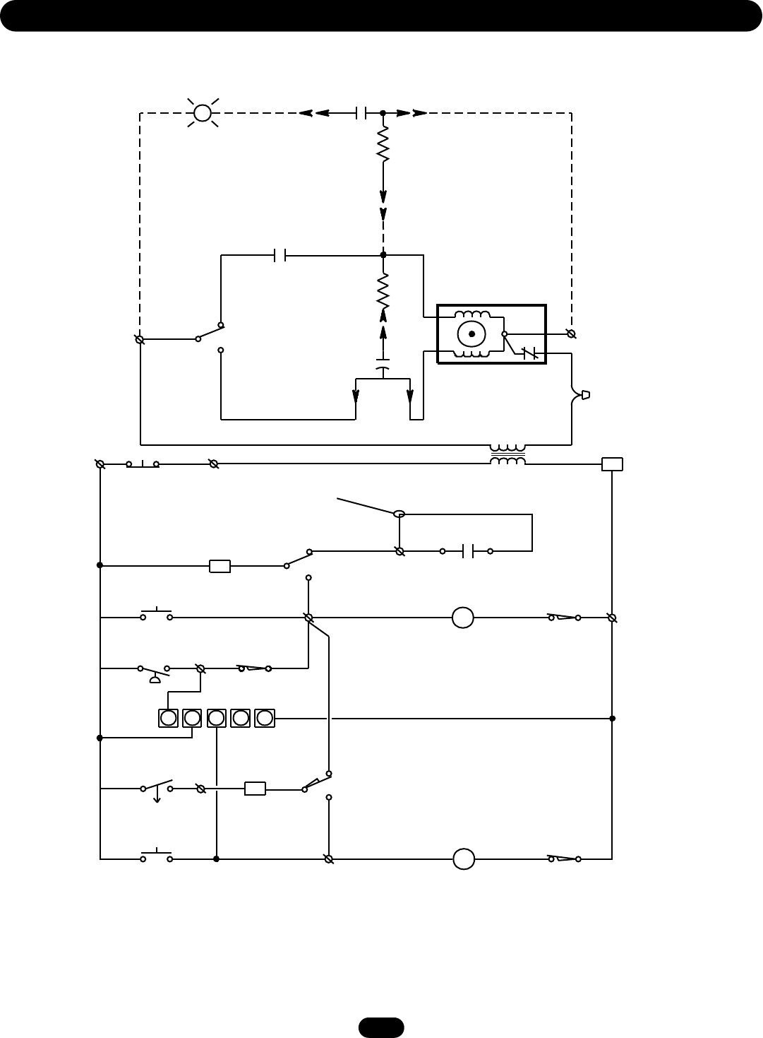
SCHEMATIC DIAGRAM FOR MT5011 • 1753
15
S
C.
E
P
I.
R
Y/BK W
CAPACITOR
OPEN
STOP
CLOSE
1234
PULL SWITCH TO
SAFETY EDGE
OPEN & CLOSE
1210711
120VAC
L2L1
OR P Y
BR
BK
Y
BL
GYY WBKBK
GROUND
OR
OP
P
CL
BL R
W
Y
BR
OR
BL
R
B
BK
R
Y
Y
NO
C
W
A
NC
NO
C
NC
BA
WIRE NUT
Y
O/L
MOTOR
BR
Y
R1
R3
R2
N.C.
N.O.
N.C.
GY
C
W
GY
P
OR
N.C.
N.C.
C
CLOSE
POR
C
W
OPEN
C
3
4
5
2
1
RADIO
REC’R
RPM
SENSOR
XFMR
AUX.CLOSE
AUX.OPEN
R
BR
ORP
TO REVERSE MOTOR DIRECTION,
INTERCHANGE RED & YELLOW WIRES.
C2 WIRING - Constant Presssure to Close
RED WIRE ON TERMINAL #12 (Shipped from Factory)
B2 WIRING - Momentary Contact to Close
MOVE RED WIRE FROM TERMINAL #12 TO TERMINAL #2
*
CLOSE CONTROL WIRING OPTIONS
Shipped from Factory
*
See Close Control
Wiring Options Below
RESISTOR
WIRE NUT
Y
WIRING DIAGRAM FOR MT5011 • 1753
16
(OPTIONAL)
BIMETAL
RELAY
CLOSE-A
* TO REVERSE MOTOR ROTATION, INTERCHANGE
RED AND YELLOW MOTOR WIRES.
PULL SWITCH
TO
OPEN & CLOSE
CLOSE
SAFETY
EDGE
OPEN
BR
2
P
7Y
10
GY
Y
AUX.
CLOSE L/S
R1 BR
1
OR
GY
AUX.
OPEN
L/S
OPEN-B
BL
OR
12
BL
C
(OPTIONAL)
LIGHT
BK
3
STOP
L2 BK
BK
CLOSE-B
4
R
OPEN-A
W
C
CAPACITOR
Y
N.O.
BL
MAX.
100W
W
C
OPEN L.S.
CLOSE L/S
PP
CL
OR
R
N.O.
R
OR
OP N.C. C
W
W
W
11
BR
L1
MOTOR *
R
Y
10VA.
PR1.
24VAC.
SEC.
Y
W
O/L BK
A
B
W
WIRE NUT
R3
R2
34 25
GY
W
R
Y
A.R.S. BOARD
(When Present)
N.C. C
MOVE JUMPER WIRE TO
TERMINAL #2 FOR MOMENTARY
CONTACT ON CLOSE
Y
HAND CHAIN
INTERLOCK SW.
(WHEN PRESENT)
BRAKE SOLENOID
CLOSE-C
OPEN-C
BL/BK
RES.
1
SCHEMATIC DIAGRAM FOR BMT5011 • 1754
17
SECONDARY
PRIMARY
W
CAPACITOR
OPEN
STOP
CLOSE
1234
PULL SWITCH
TO OPEN &
CLOSE
SAFETY
EDGE
1210711
RATED LINE
VOLTAGE
L2L1
OR PYBR
BK
Y
BLGYY BKBK
GROUND
OR
OP
P
CL
BL R
W
BL
BR
OR
BL
R
BK
R
Y
Y
W
WIRE NUT
Y
O/L
MOTOR
BR R1
R3
R2
GY
W
CLOSE
P
OR
OPEN
3
4
5
2
1
RADIO
REC’R
XFMR
AUX.CLOSE
AUX.OPEN
R
BR
P
NO
C
NC
BA
NO
C
NC
C
NO
C
NC
BA
NO
C
NC
C
BRAKE
SOLENOID
N.O.
COM
INTLK.
Y
INTERLOCK SWITCH (WHEN SUPPLIED)
WIRED N.O. HELD CLOSED.
**
**
TO REVERSE MOTOR DIRECTION,
INTERCHANGE RED & YELLOW WIRES.
C2 WIRING - Constant Presssure to Close
RED WIRE ON TERMINAL #12 (Shipped from Factory)
B2 WIRING - Momentary Contact to Close
MOVE RED WIRE FROM TERMINAL #12 TO TERMINAL #2
*
CLOSE CONTROL WIRING OPTIONS
Shipped from Factory
*
See Close Control
Wiring Options Below
W
BL/BK
BL/BK
BL/BK
A.R.S. BOARD
(When Present)
Y
W
N.C.
COM
COM
N.C.
N.O. GY
N.C.
OR
W
COM
P
R
Y
R
RESISTOR
Y
GY
WIRING DIAGRAM FOR BMT5011 • 1754
18
6
1
9
3
L4
L2
S5 S1
S2
S4
S3
L3
S4
S3
L1
L3
L7
L5
L2
10
L7
7
4
5
8
2
L6
11
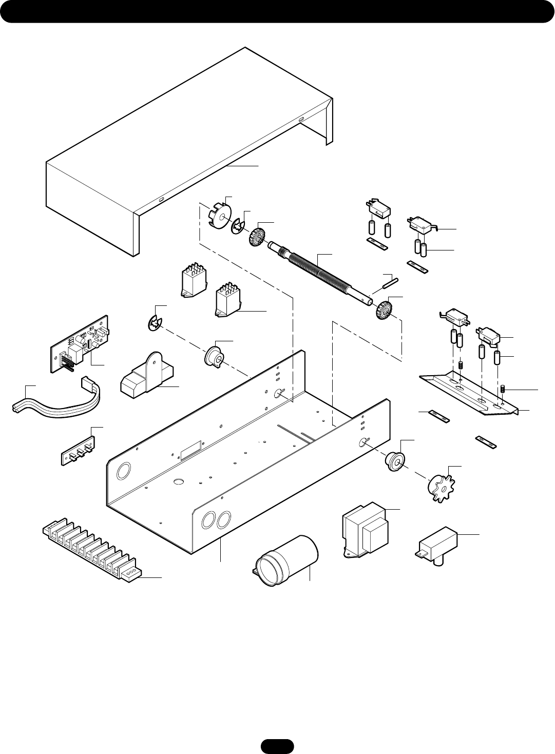
ELECTRICAL BOX

19
Below are replacement kits available for your operator. For replacement of electrical box, motor or brake components be sure to match
model number of your unit to kit number below to ensure proper voltage requirements. Optional modifications and/or accessories
included with your operator may add or remove certain components from these lists. Please consult a parts and service representative
regarding availability of individual components of kits specified below. Refer to page 13 for all repair part ordering information.
Complete Electrical Box
K-MT5011 Model MT5011, 115V Single Phase
K-MT5025 Model MT5025, 230V 50Hz
K-BMT5011 Model BMT5011, 115V Single Phase
K-BMT5025 Model BMT5025, 230V 50Hz
Electrical Box Sub-Assemblies
K72-12487 Limit Shaft Assembly
K75-12493 Limit Switch Assembly
K75-12489 Auto Reversal System(ARS) PCB
REPAIR PARTS - ELECTRICAL BOX
INDIVIDUAL PARTS
ITEM PART # DESCRIPTION QTY
1 10-10315 MT Electrical Box 1
2 10-10316 MT Electrical Box Cover 1
3 23-10916 SPDT Interlock Switch
(Not on MT) 1
4 29-2 Resistor, 2 Ohm 1
5 42-10040 Terminal Assembly 3 Lug 1
6 42-110 10 Position Terminal Block 1
7 71-10345 RPM Sensor Board (MT Only) 1
8 74-10352 RPM Sensor Board Harness 1
9 (See Var. Comp.) Transformer 1
10 (See Var. Comp.) Relay, 24V 2
11 (See Var. Comp.) Motor Capacitor 1
Not Shown
31-10350 Standoff
K75-12489 MT Auto Reversal System
(ARS) Logic
VARIABLE COMPONENT KITS
PART # DESCRIPTION
13-10024 Limit Nut • • • •
23-10041 Limit Switch • • • •
29-2 Resistor, 2 Ohm • • • •
21-10340 Transformer, 115V • •
21-5230 Transformer, 230V • •
29-10338 Capacitor, 70MFD • •
29-12110 Capacitor, 20MFD • •
24-24-1 Relay, DPDT • •
24-24-6 Relay, 3PDT • •
MT5011
MT5025
BMT5011
BMT5025
K75-12493 • LIMIT SWITCH ASSEMBLY KIT
ITEM PART # DESCRIPTION QTY
S1 Depress Plate 1
S2 Spring, Depress Plate 2
S3 23-10041 Limit Switch 4
S4 Standoff, Limit Switch 8
S5 Nut, Double Tinnerman 4
K72-12487 • LIMIT SHAFT ASSEMBLY KIT
ITEM PART # DESCRIPTION QTY
L1 11-10321 Limit Shaft 1
L2 Flange Bearing 3/8" I.D. 2
L3 13-10024 Limit Nut 2
L4 Sprocket 48B9 x 3/8"
Powder Metal 1
L5 RPM Sensor Interrupter Cup 1
L6 Rollpin 1/8 x 1" Long 1
L7 E Ring, 3/8" 2
Motor Kits
K20-5150LD Models MT5011, BMT5011
K20-5250LD Models MT5025, BMT5025
20
Brake Componets Model BMT Only
Brake Componets - Model BMT Only
B4
B7
O6
O4
O9
O5
O7
O2
O2
O3
O1
C3
O8
O8
O8
C13
C3
1
B10
B5
B9
B1
B3
B6
MTR
B8 C1
C8
C5
C6
C7
C9
C10
C4
C11
C12
C2
B11
B2
3
H5
H8
H6
H4
H3
4
H2
H1
H7
C14
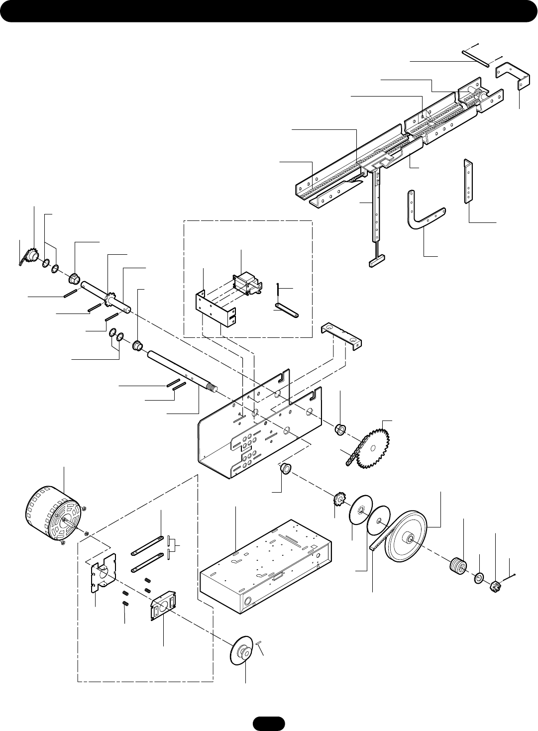
ILLUSTRATED PARTS

21
Refer to the parts lists below for replacement kits available for your operator. If optional modifications and/or accessories are included
with your operator, certain components may be added or remove from these lists. Individual components of each kit may not be
available. Please consult a parts and service representative regarding availability of individual components. Refer to page 13 for all
repair part ordering information.
REPAIR PARTS KITS
BRAKE ASSEMBLY KITS
ITEM PART # DESCRIPTION QTY
B1 10-10354 Brake Release Arm 2
B2 10-10355 Solenoid Link 1
B3 10-10356 Brake Mounting Plate 1
B4 10-10357 Solenoid Bracket 1
B5 17-10363 Pulley & Disc Assembly 1
B6 Compression Spring
.360 O.D. x .045WD 4
B7 22-120 115V Brake Solenoid 1
22-240 230V Brake Solenoid 1
B8 31-10364 Spacer .20 I.D. x .260 OD x 1 2
B9 75-10359 Brake Plate Pad Assembly 1
B10 82-NH25-03 1/4-20 x 3/16 S.S. Knurled Cup 1
B11 86-CP05-108 Cotterpin 5/32" x 1-1/2" Long 1
K75-12492 Model BMT5011
K75-12494 Model BMT5025
Brake kits for model BMT only
K72-12471 CLUTCH SHAFT ASSEMBLY KIT
ITEM PART # DESCRIPTION QTY
C1 10-10166 Clutch Plate 1
C2 11-10320 Clutch Shaft 1
C3 12-10029 Bearing 3/4" I.D. 2
C4 15-48B10GXX Sprocket, 48B10 x 3/4" 1
C5 16-4L290 Cogged Belt 1
C6 17-10336 4L Motor Pulley 7" O.D. 1
C7 18-10164 Spring, Clutch (1/3 & 1/2 HP) 1
C8 39-10167 Clutch Disc 1
C9 84-SH-76 Castle Nut 3/4-16 1
C10 86-CP04-112 Cotterpin 1/8" x 1-3/4" Long 1
C11 86-RP08-102 Roll Pin 1/4" x 1-1/8" Long 1
C12 86-RP08-200 Roll Pin 1/4" x 2" Long 1
C13 87-P-075 Turac 3/4" Push on Fastener 2
C14 85-FW-75 Flatwasher 3/4" 5
K72-12472 OUTPUT SHAFT KIT
ITEM PART # DESCRIPTION QTY
O1 11-10319 Output Shaft 1
O2 12-10029 Bearing 3/4" I.D. 2
O3 15-48B10GXX Sprocket, 48B10 x 3/4" 1
O4 15-48B10G1 Sprocket, 48B10 x 3/4"
Powder Metal 1
O5 15-48B24GXX Sprocket, 48B24 x 3/4" 1
O6 19-48027M Chain #48 x 27 Links
with master link 1
O7 19-48033M Chain #48 x 33 Links
with master link 1
O8 86-RP08-102 Roll Pin 1/4" x 1-1/8" Long 3
O9 87-P-075 Turac 3/4" Push on Fastener 2
DOOR TRACK & DRIVE CHAIN
ITEM PART # DESCRIPTION
3 19-5810 #48 Chain Doors 8' to 10'
19-5812 #48 Chain Doors to 12'
19-5814 #48 Chain Doors to 14'
4 Door Track*
*Call for pricing and availability.
K77-12486 HARDWARE KIT
ITEM PART # DESCRIPTION QTY
H1 10-10203 Curved Arm 1
H2 10-10204 Door Bracket 1
H3 10-10205 Header Bracket 1
H4 11-10130 Header Pivot Pin 1
H5 75-10170 Slider Assembly 1
H6 75-10174 Front Idler Assembly 1
H8 75-10259 Track Spacer Assembly 2
H1 10-10203 Curved Arm 1
H2 10-10204 Door Bracket 1
H7 75-10214 Straight Arm Assembly 1
K75-12870 STRAIGHT & CURVED ARM ASSEMBLY
Heavy Duty Straight Arm
PART # DESCRIPTION
K75-17034 Upgrade Kit
MOTOR
See page 19 for more information.
ELECTRICAL BOX REPLACEMENT KITS
ITEM DESCRIPTION KIT #
EB Electrical Box Replacement Kits See page 19

22
OPERATOR NOTES

23
OPERATOR NOTES
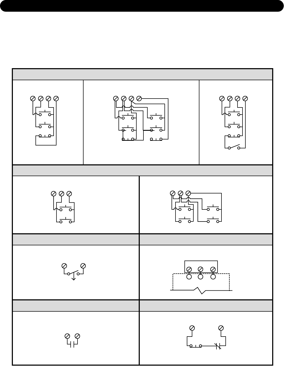
OPEN TIMER TO CLOSE
3 BUTTON STATION OR 3 POSITION KEYSWITCH WITH SPRING RETURN TO CENTER AND STOP BUTTON
R1 R2 R3
2 BUTTON STATION OR 3 POSITION KEYSWITCH WITH SPRING RETURN TO CENTER
STANDARD
1 2 4
Close
Open
2 OR MORE
1 2 4
Close
Open
Close
Open
STOP
34
RADIO CONTROL
RESIDENTIAL RADIO CONTROLS1 BUTTON STATION OR ANY AUXILIARY DEVICE
EXTERNAL INTERLOCK
310
EXT.
INTERLOCK
STANDARD
1 2 3 4
Stop
Close
Open
IMPORTANT NOTES:
1) The 3-Button Control Station provided must be connected for operation.
2) If a STOP button is not used, a jumper must be placed between terminals 3 and 4.
3) Auxiliary control equipment may be any normally open two wire device such as pullswitch, single button,
loop detector, card key or such device.
4)
When adding accessories, install them one at a time and test each one after it is added to ensure proper installation and
operation with the Commercial Door Operator.
5) Attention Electrician: Use 16 gauge or heavier wire for all control circuit wiring.
Sensing Device
EXTERNAL
TERMINAL BLOCK
SENSING DEVICE TO REVERSE OR STOP
KEY LOCKOUT
1 2 3 4
Stop
Close
Open
Keyswitch
SEE NOTE #2
SEE NOTE #2
37
To Open, Close and Reverse while closing
2 OR MORE
1 2 3 4
Stop
Close
Open
Stop
Close
Open
CONTROL CONNECTION DIAGRAM
©2008, The Chamberlain Group, Inc.
01-10332N All Rights Reserved
