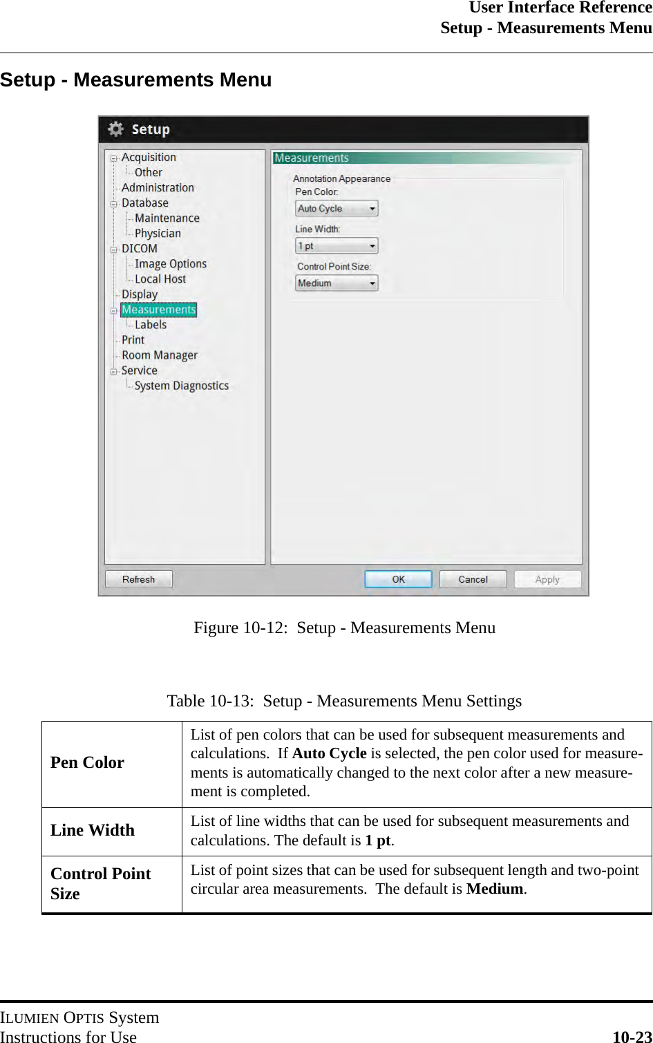
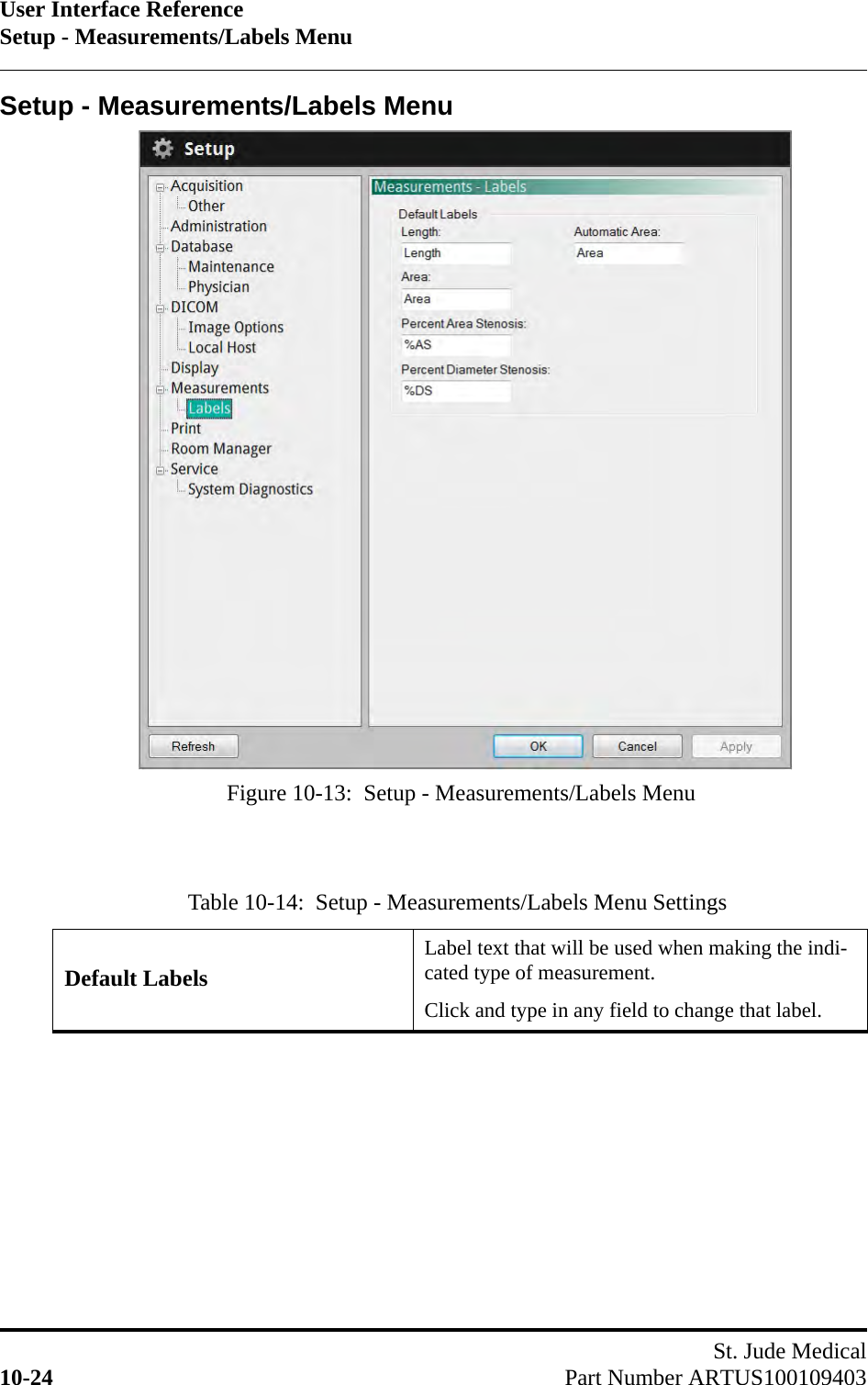
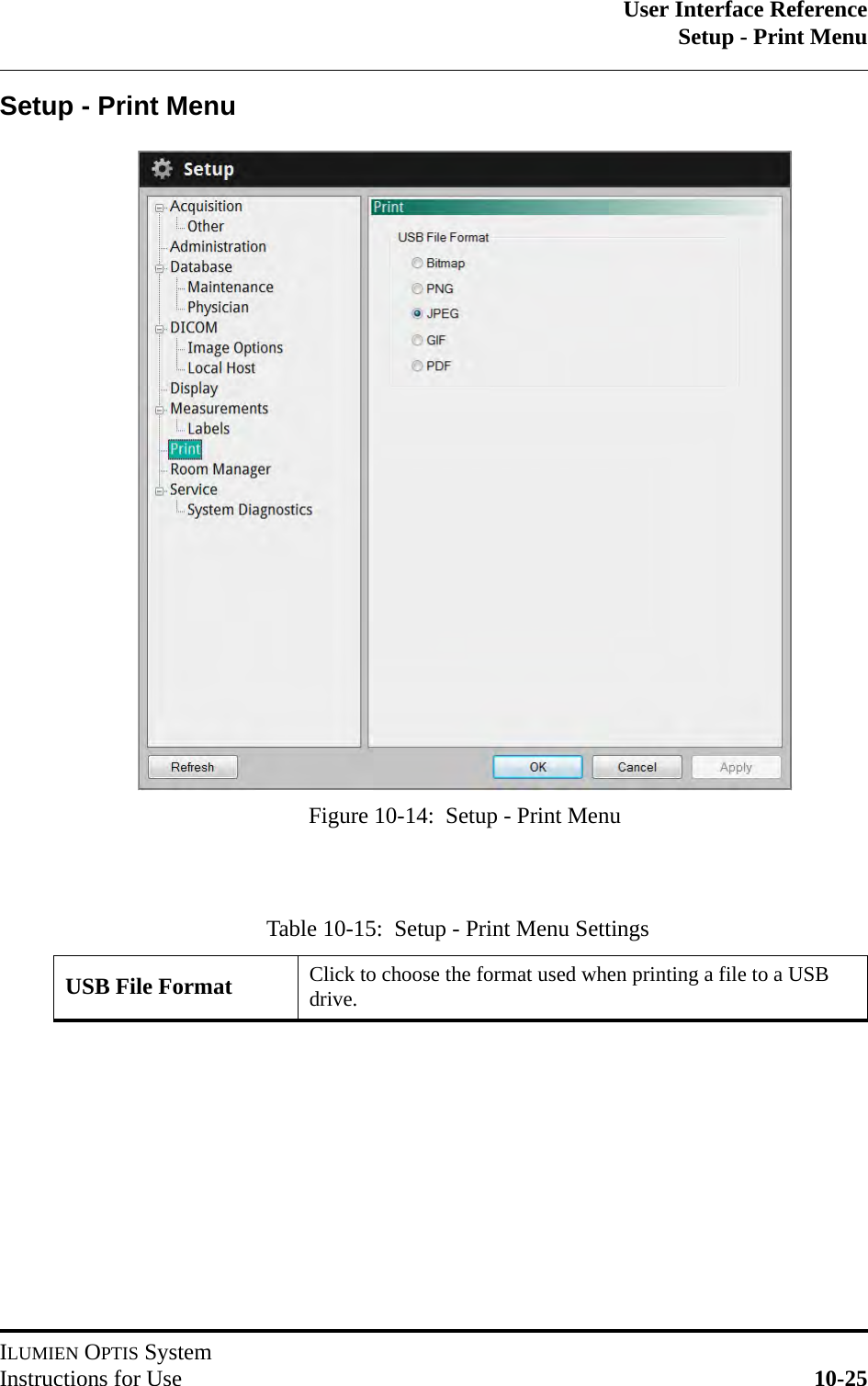
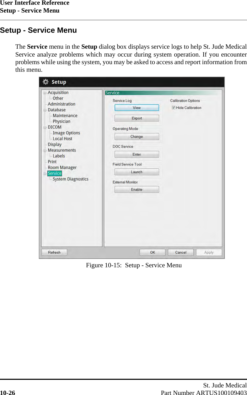
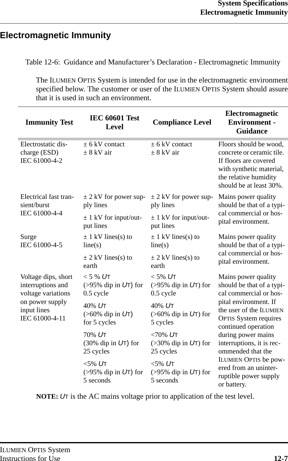
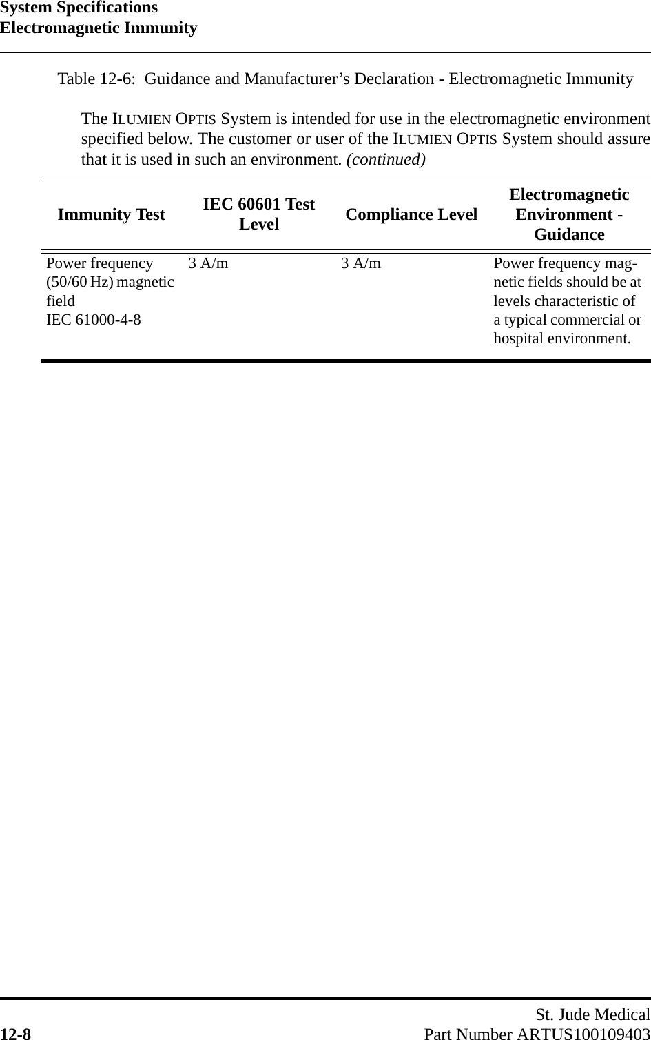
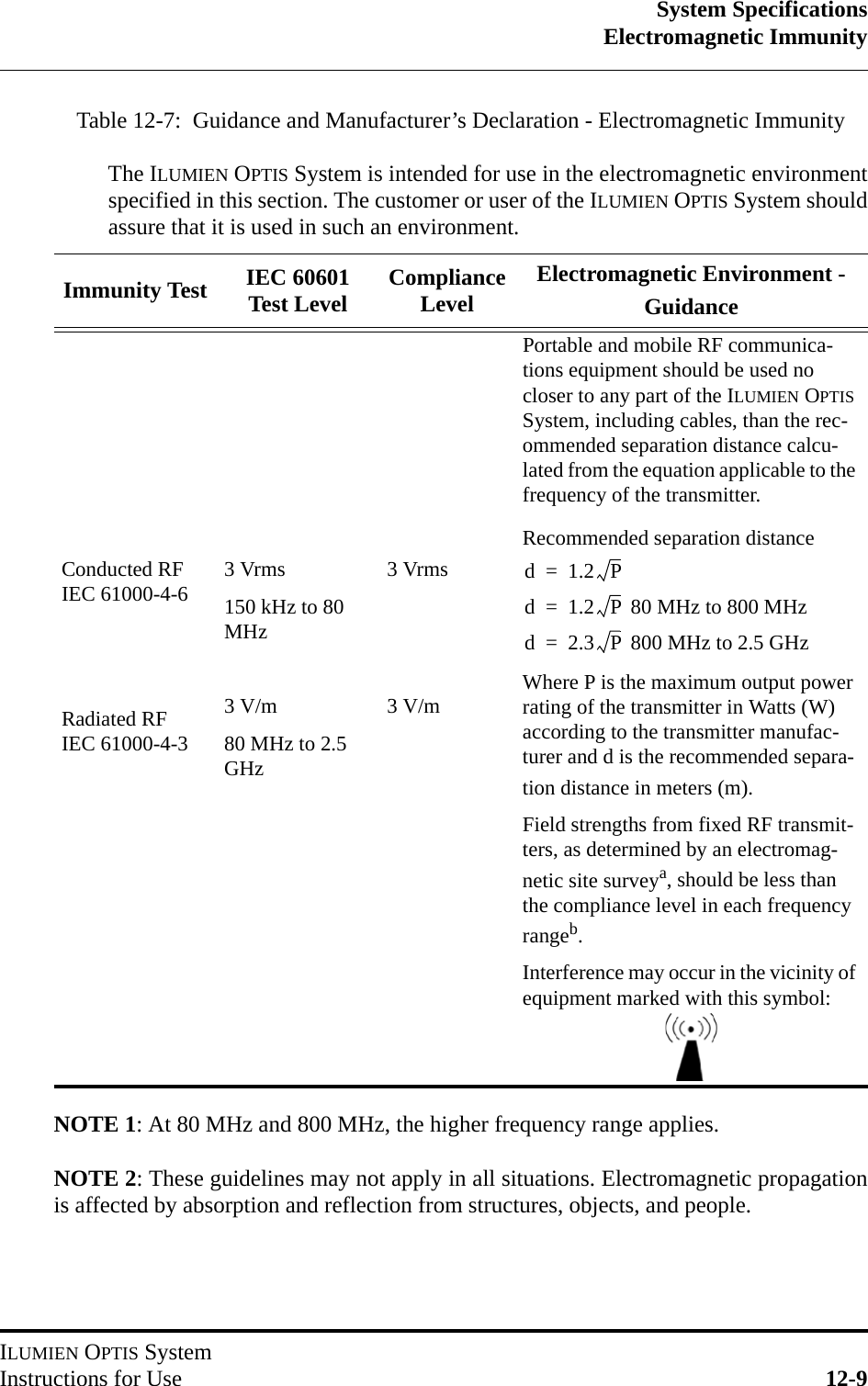
LightLab Imaging C408652 C8i User Manual Optis Integrated IFU US E1 Draft
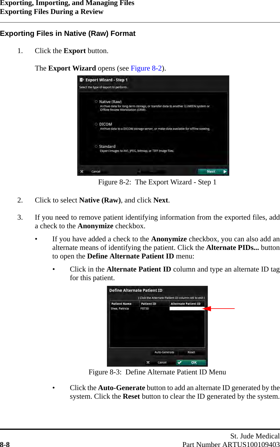
LightLab Imaging Inc C8i Optis Integrated IFU US E1 Draft
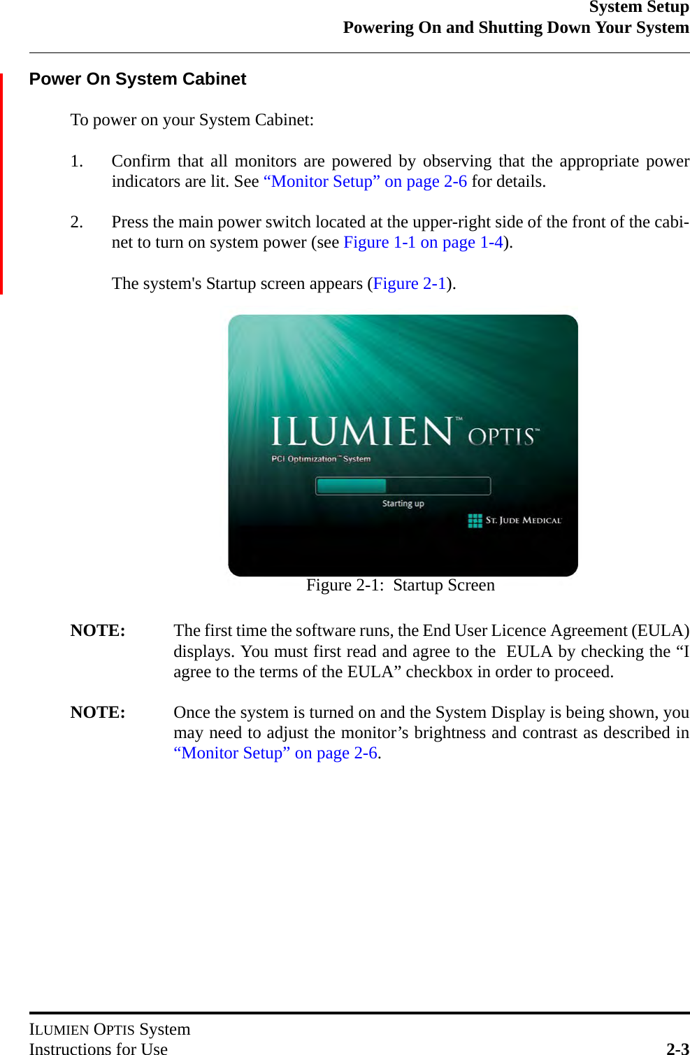
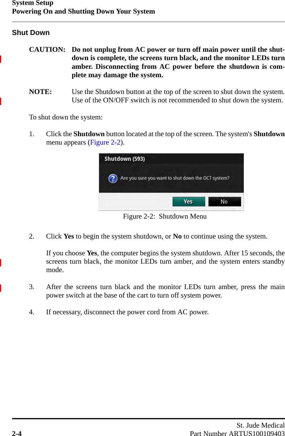
UserManual.wiki
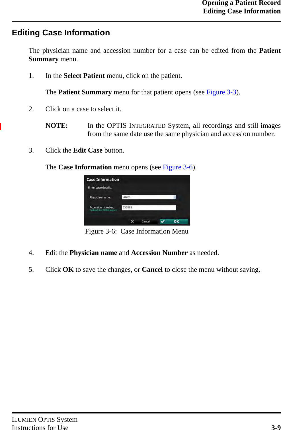
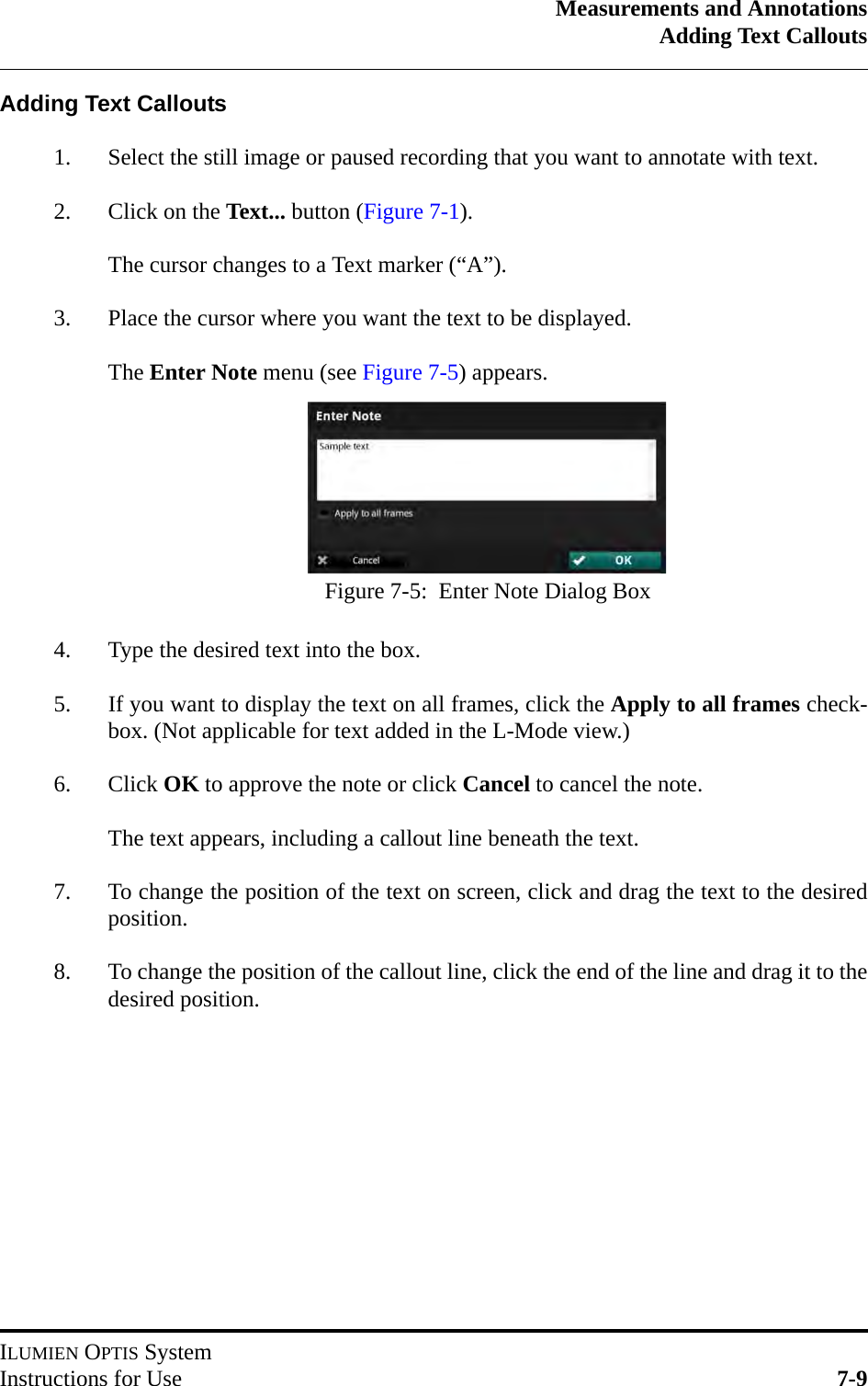
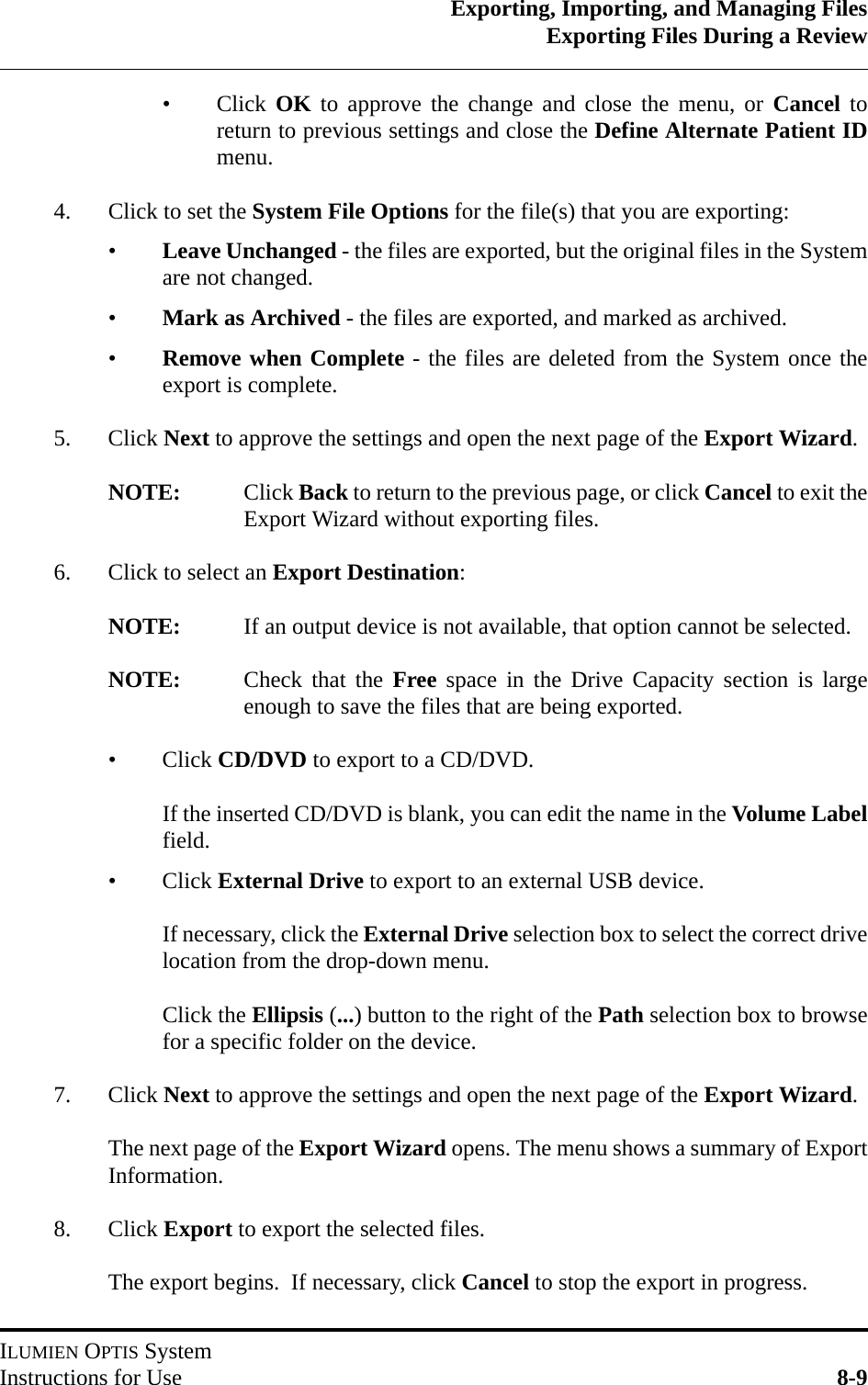
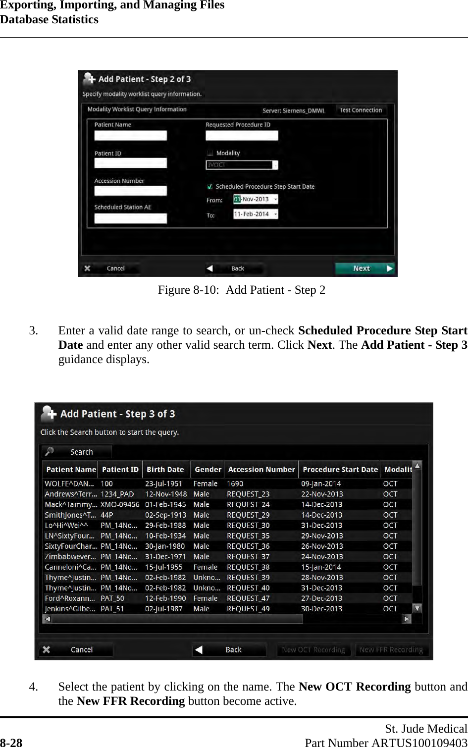
>
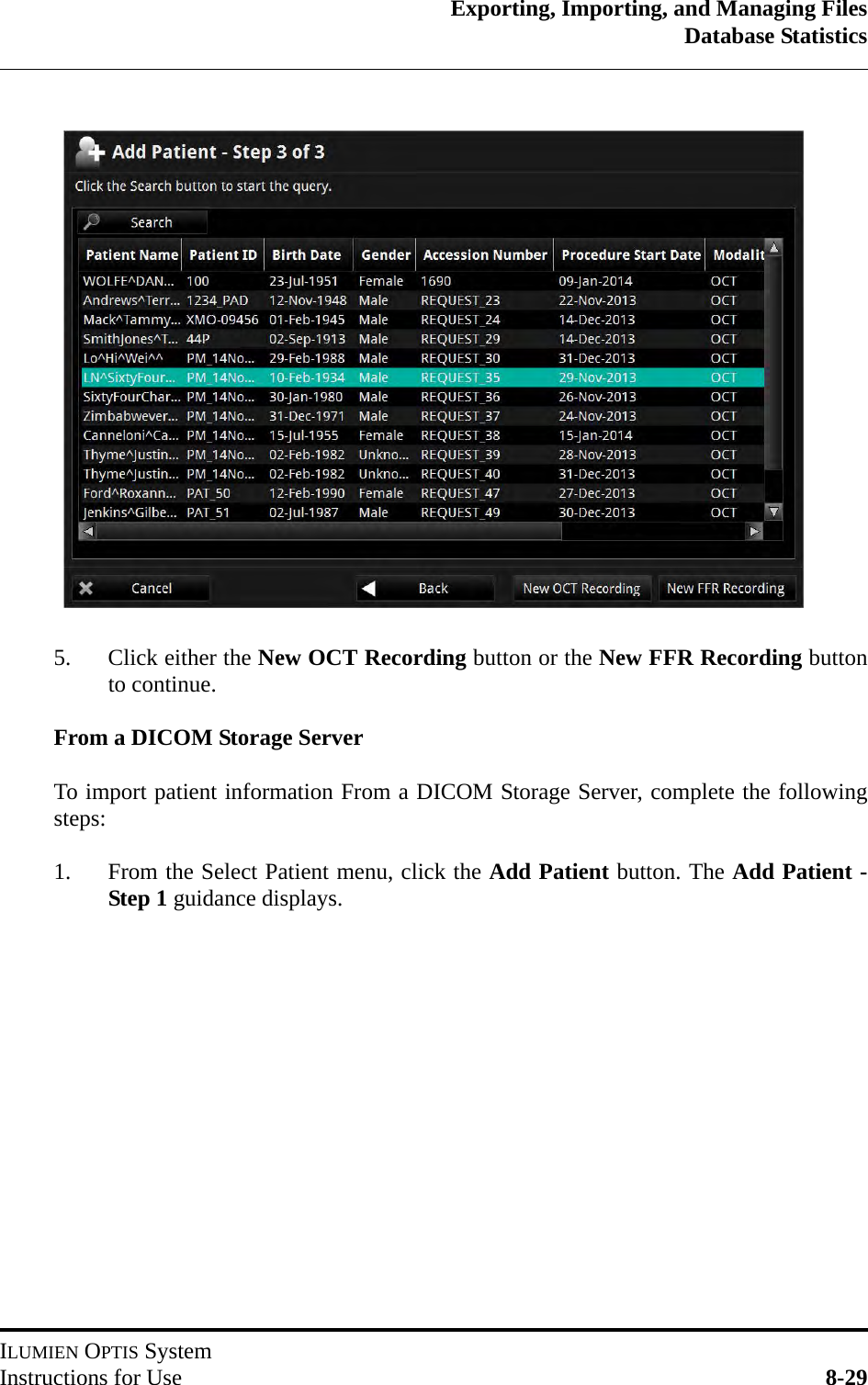
LightLab Imaging
>
C408652 User Manual
User Manual.pdf
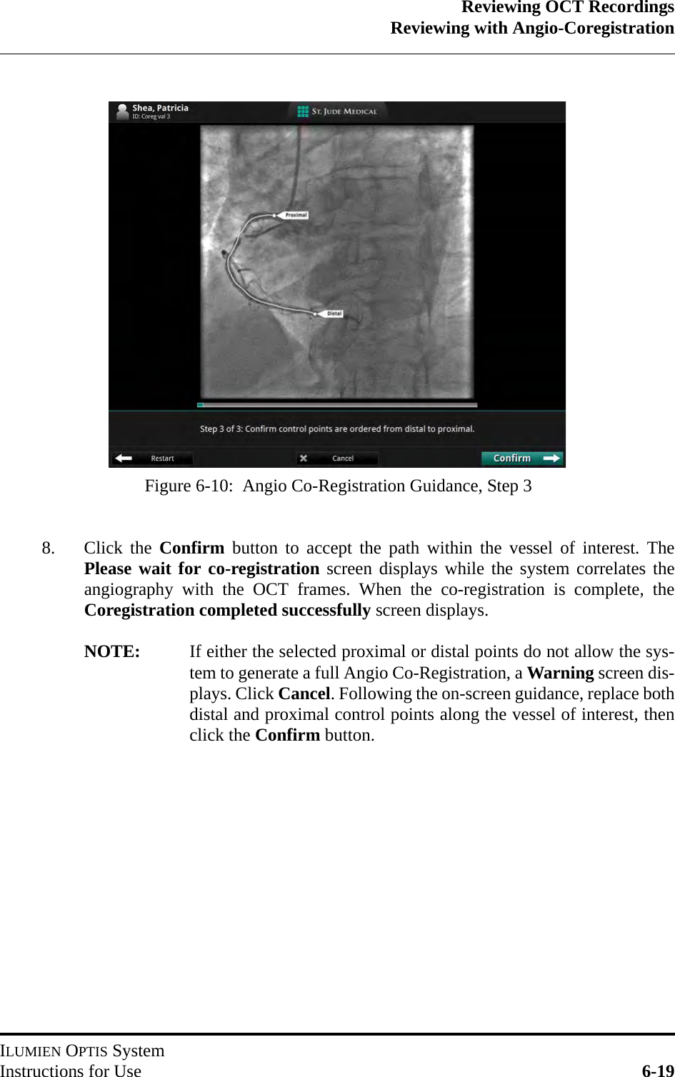
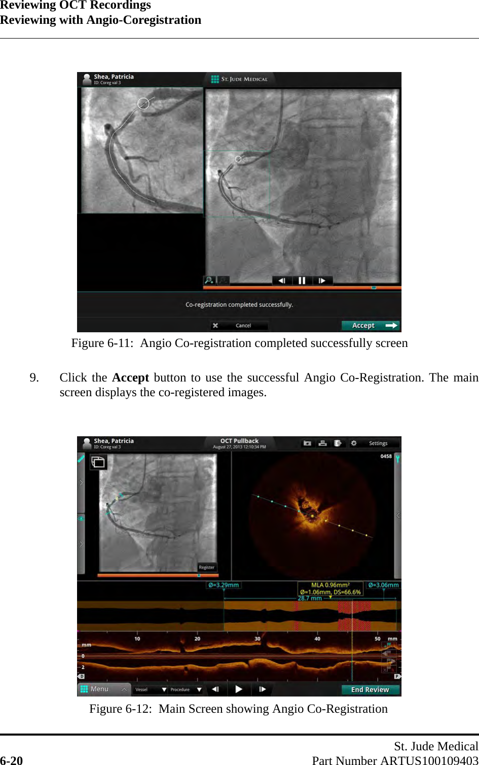
Navigation menu
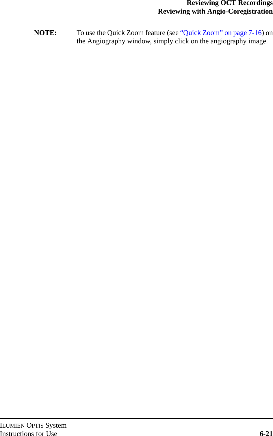
Upload a User Manual
Namespaces
Wiki Guide
HTML
PDF
Info
Views
User Manual
Discussion / Help
Navigation