LightLab Imaging C408652 C8i User Manual Optis Integrated IFU US E1 Draft
LightLab Imaging Inc C8i Optis Integrated IFU US E1 Draft
User Manual.pdf
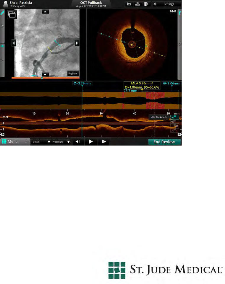
OPTIS™ Integrated System
Instructions for Use
Information provided within this Document is subject to change without notice and although believed to
be accurate, St. Jude Medical, Inc. and its affiliated companies including without limitation, St. Jude
Medical System AB (Sweden), assume no responsibility for any errors, omissions or inaccuracies.
©2014 St. Jude Medical, Inc. and its related companies. All rights reserved. Reproduction, adaptation,
or translation without prior permission is prohibited, except as allowed under copyright laws.
OPTIS Integrated systems are subject to US Patents 8,412,312, 8,325,419, 6,565,514; GB, FR
0883793, DE 69738291. ILUMIEN, OPTIS, ST. JUDE MEDICAL, LIGHTLAB IMAGING, GOLDEN
IMAGE and the color gold are registered or unregistered trademarks of St. Jude Medical, Inc. and its
related companies.
The OPTIS INTEGRATED system software incorporates third party licensed software as described at the
following URL: www.sjmprofessional.com/ilumien-legal-notices
St. Jude Medical Coordination Center BVBA Australian Sponsor:
The Corporate Village St. Jude Medical Australia Pty Limited
Da Vincilaan 11 Box F1 17 Orion Rd.,
1935 Zaventem Belgium Lane Cove NSW 2066 Australia
+32 2 774 68 11 +61 2 9936 1200
LightLab Imaging, Inc. Phone: +1 855 478 5833 US Toll-free
4 Robbins Road +1 651 756 5833 International
Westford, MA 01886
USA
www.sjm.com
Service E-mail: OCTservice@sjm.com
Part Number ARTUS100109403
ENGLISH
Printed in the U.S.A. 4 / 2014
CAUTION: Federal law restricts this device to sale by or on the order of a Physician licensed by
law of the state in which he practices to use or order the use of the device.

ILUMIEN OPTIS System
Instructions for Use iii
SAFETY INFORMATION
Please review this manual carefully before using your OPTIS Integrated System, especially the safety
information in Chapter 11 “Safety Information”. Also, especially note Warnings and Cautions shown
throughout the manual.
WARNINGS
Electrical Shock Hazard
Do not remove OPTIS INTEGRATED System covers. To avoid electrical shock, use only the power cord
supplied with the system and connect only to properly grounded wall outlets. See Chapter 2 “System
Setup” and Chapter 11 “Safety Information” for electrical safety information.
Explosion Hazard
Do not operate the OPTIS INTEGRATED System in the presence of flammable anesthetics. Doing so
could lead to an explosion.
Visible and Invisible Laser Radiation
Do not stare into the beam or view the beam directly with optical instruments. Doing so may cause seri-
ous eye damage and hazardous radiation exposure.
Using These Instructions for Use
This manual describes the St. Jude Medical OPTIS Integrated System. In it you will find:
• Descriptions of system components and user interface.
• Procedures for using the system for both Optical Coherence Tomography (OCT) and Frac-
tional Flow Reserve Rate (FFR) procedures.
• System safety and cleaning information.
• System specifications.

iv
Conventions Used in These Instructions for Use
• These abbreviations and shortened expressions are used throughout this manual.
• Software text, and physical button labels are shown in bold type. Examples: the Patient
Summary menu, Settings button.
• Keyboard keys are shown enclosed in carets. Examples: <Enter>, <Ctrl>, <Tab>.
• Warnings, Cautions, and Notes are set apart from other text and appear as shown below.
WARNING: Warnings alert the user to the possibility of injury, death, or
other serious adverse reactions associated with product use or
misuse.
CAUTION: Cautions alert the user to the possibility of a problem with the
product associated with its use or misuse. Problems can include
product malfunctions, product failure, and/or damage to the
product or damage to other property, or loss of data.
NOTE: Notes provide additional information.
Other Instructions for Use
Details of the imaging catheter are covered in the Dragonfly Imaging Catheter Instructions for Use pro-
vided with the catheters and are not covered in this manual.
Details of the PressureWire are covered in the PressureWire Instructions for Use and are not covered in
this manual.
NOTE: Additionally, this manual does not provide detailed discussion of the sys-
tem components, except as they are used with the OPTIS Integrated Sys-
tem.
Table Front-1: Instructions for Use Conventions
Dialog Box or Menu A window that solicits a user response.
Click or Left-click Click the left mouse button or the Select button on the Table Side
Controller.
Double-click Click the left mouse button or the Select button on the Table Side
Controller twice in quick succession.
Select Highlight a menu item with the mouse or the tab or arrow keys or
the Navigation Controller on the Table Side Controller.

ILUMIEN OPTIS System
Instructions for Use i
Contents
Figures
Tables
System Overview
Optis Integrated System Features . . . . . . . . . . . . . . . . . . . . . . . . . . . . . . . . . . . . . .1-1
OPTIS Integrated System Components. . . . . . . . . . . . . . . . . . . . . . . . . . . . . . . . . .1-2
OPTIS Integrated System Accessories. . . . . . . . . . . . . . . . . . . . . . . . . . . . . .1-3
Optis Integrated System Cabinet and Control Room Components . . . . . . . .1-4
Optis Integrated System - Mobile Workstation . . . . . . . . . . . . . . . . . . . . . . .1-5
OPTIS Integrated System Table Side Controller . . . . . . . . . . . . . . . . . . . . . .1-6
OPTIS Integrated System DOC Holster. . . . . . . . . . . . . . . . . . . . . . . . . . . . .1-7
OPTIS Integrated Symbols. . . . . . . . . . . . . . . . . . . . . . . . . . . . . . . . . . . . . . .1-8
The Drive-motor and Optical Controller (DOC). . . . . . . . . . . . . . . . . . . . . . . . . . .1-10
The Wi-Box . . . . . . . . . . . . . . . . . . . . . . . . . . . . . . . . . . . . . . . . . . . . . . . . . . . . . . .1-11
Indications for Use and Intended Use . . . . . . . . . . . . . . . . . . . . . . . . . . . . . . . . . . .1-12
Contraindications. . . . . . . . . . . . . . . . . . . . . . . . . . . . . . . . . . . . . . . . . . . . . . . . . . .1-13
Warnings (OCT) . . . . . . . . . . . . . . . . . . . . . . . . . . . . . . . . . . . . . . . . . . . . . . . . . . .1-14
Precautions (OCT). . . . . . . . . . . . . . . . . . . . . . . . . . . . . . . . . . . . . . . . . . . . . . . . . .1-15
Complications (OCT) . . . . . . . . . . . . . . . . . . . . . . . . . . . . . . . . . . . . . . . . . . . . . . .1-16
Warnings and Precautions (FFR). . . . . . . . . . . . . . . . . . . . . . . . . . . . . . . . . . . . . . .1-17
Connecting to External Equipment/Accessories . . . . . . . . . . . . . . . . . . . . . .1-17
Mechanical Enclosure . . . . . . . . . . . . . . . . . . . . . . . . . . . . . . . . . . . . . . . . . .1-17
Electrical. . . . . . . . . . . . . . . . . . . . . . . . . . . . . . . . . . . . . . . . . . . . . . . . . . . . .1-17
Electronic Interference . . . . . . . . . . . . . . . . . . . . . . . . . . . . . . . . . . . . . . . . . .1-17

Contents
ii
Aortic Reference Pressure . . . . . . . . . . . . . . . . . . . . . . . . . . . . . . . . . . . . . . .1-18
Pressure Averaging (Mean Setting) . . . . . . . . . . . . . . . . . . . . . . . . . . . . . . . .1-18
Defibrillation . . . . . . . . . . . . . . . . . . . . . . . . . . . . . . . . . . . . . . . . . . . . . . . . .1-18
Recording . . . . . . . . . . . . . . . . . . . . . . . . . . . . . . . . . . . . . . . . . . . . . . . . . . . .1-18
System Setup
Positioning the System. . . . . . . . . . . . . . . . . . . . . . . . . . . . . . . . . . . . . . . . . . . . . . .2-1
Connecting Your System. . . . . . . . . . . . . . . . . . . . . . . . . . . . . . . . . . . . . . . . . . . . .2-2
System Connections . . . . . . . . . . . . . . . . . . . . . . . . . . . . . . . . . . . . . . . . . . . .2-2
Powering On and Shutting Down Your System . . . . . . . . . . . . . . . . . . . . . . . . . . .2-2
Power On System Cabinet . . . . . . . . . . . . . . . . . . . . . . . . . . . . . . . . . . . . . . .2-3
Shut Down . . . . . . . . . . . . . . . . . . . . . . . . . . . . . . . . . . . . . . . . . . . . . . . . . . .2-4
FFR Settings . . . . . . . . . . . . . . . . . . . . . . . . . . . . . . . . . . . . . . . . . . . . . . . . . . . . . .2-5
Monitor Setup . . . . . . . . . . . . . . . . . . . . . . . . . . . . . . . . . . . . . . . . . . . . . . . . . . . . .2-6
Setting Monitor Functions . . . . . . . . . . . . . . . . . . . . . . . . . . . . . . . . . . . . . . .2-6
Setting Monitor Position . . . . . . . . . . . . . . . . . . . . . . . . . . . . . . . . . . . . . . . .2-6
Opening a Patient Record
Select Patient Menu (Home Menu) . . . . . . . . . . . . . . . . . . . . . . . . . . . . . . . . . . . . .3-2
Patient Summary Menu . . . . . . . . . . . . . . . . . . . . . . . . . . . . . . . . . . . . . . . . . . . . . .3-4
Entering New Patient Information. . . . . . . . . . . . . . . . . . . . . . . . . . . . . . . . . . . . . .3-6
Editing Patient Information . . . . . . . . . . . . . . . . . . . . . . . . . . . . . . . . . . . . . . . . . . .3-8
Editing Case Information. . . . . . . . . . . . . . . . . . . . . . . . . . . . . . . . . . . . . . . . . . . . .3-9
Importing a Patient Database. . . . . . . . . . . . . . . . . . . . . . . . . . . . . . . . . . . . . . . . . .3-10
Opening a Saved Recording or Still Image . . . . . . . . . . . . . . . . . . . . . . . . . . . . . . .3-11
Performing an FFR Procedure
Overview . . . . . . . . . . . . . . . . . . . . . . . . . . . . . . . . . . . . . . . . . . . . . . . . . . . . . . . . .4-1
Required Material and Equipment . . . . . . . . . . . . . . . . . . . . . . . . . . . . . . . . .4-1
Setting up the OPTIS Integrated System. . . . . . . . . . . . . . . . . . . . . . . . . . . . . . . . .4-2
Setting up the Wi-Box with the OPTIS Integrated System . . . . . . . . . . . . . . . . . . .4-3
Setting up the PressureWire. . . . . . . . . . . . . . . . . . . . . . . . . . . . . . . . . . . . . . . . . . .4-4

Contents
ILUMIEN OPTIS System
Instructions for Use iii
Preparing to Record FFR. . . . . . . . . . . . . . . . . . . . . . . . . . . . . . . . . . . . . . . . . . . . .4-5
Recording FFR. . . . . . . . . . . . . . . . . . . . . . . . . . . . . . . . . . . . . . . . . . . . . . . . . . . . .4-11
Reviewing an FFR Recording . . . . . . . . . . . . . . . . . . . . . . . . . . . . . . . . . . . . . . . . .4-13
PressureWire Troubleshooting . . . . . . . . . . . . . . . . . . . . . . . . . . . . . . . . . . . . . . . .4-15
Performing an OCT Procedure
Overview . . . . . . . . . . . . . . . . . . . . . . . . . . . . . . . . . . . . . . . . . . . . . . . . . . . . . . . . .5-1
Required Material and Equipment . . . . . . . . . . . . . . . . . . . . . . . . . . . . . . . . .5-1
OCT Imaging Overview. . . . . . . . . . . . . . . . . . . . . . . . . . . . . . . . . . . . . . . . .5-2
OCT Operating Modes. . . . . . . . . . . . . . . . . . . . . . . . . . . . . . . . . . . . . . . . . . . . . . .5-3
OCT Recording Types. . . . . . . . . . . . . . . . . . . . . . . . . . . . . . . . . . . . . . . . . . . . . . .5-3
OCT Trigger Types . . . . . . . . . . . . . . . . . . . . . . . . . . . . . . . . . . . . . . . . . . . . . . . . .5-4
Angio-Coregistration . . . . . . . . . . . . . . . . . . . . . . . . . . . . . . . . . . . . . . . . . . . . . . . .5-5
Setting up the OPTIS Integrated System. . . . . . . . . . . . . . . . . . . . . . . . . . . . . . . . .5-5
Setting up the DOC . . . . . . . . . . . . . . . . . . . . . . . . . . . . . . . . . . . . . . . . . . . . . . . . .5-6
Setting up the Dragonfly Imaging Catheter. . . . . . . . . . . . . . . . . . . . . . . . . . . . . . .5-7
Preparing to Acquire OCT Recordings . . . . . . . . . . . . . . . . . . . . . . . . . . . . . . . . . .5-8
Confirm Recording Settings . . . . . . . . . . . . . . . . . . . . . . . . . . . . . . . . . . . . . . . . . .5-12
Dragonfly Imaging Catheter Insertion and Positioning. . . . . . . . . . . . . . . . . . . . . .5-13
Acquiring Patient Images. . . . . . . . . . . . . . . . . . . . . . . . . . . . . . . . . . . . . . . . . . . . .5-16
Removing the Dragonfly Imaging Catheter. . . . . . . . . . . . . . . . . . . . . . . . . . . . . . .5-18
Troubleshooting OCT Acquisition . . . . . . . . . . . . . . . . . . . . . . . . . . . . . . . . . . . . .5-19
Immediately Stopping DOC Operation . . . . . . . . . . . . . . . . . . . . . . . . . . . . .5-19
Catheter Failure . . . . . . . . . . . . . . . . . . . . . . . . . . . . . . . . . . . . . . . . . . . . . . .5-20
Reviewing OCT Recordings
Image Window. . . . . . . . . . . . . . . . . . . . . . . . . . . . . . . . . . . . . . . . . . . . . . . . . . . . .6-2
L-Mode View. . . . . . . . . . . . . . . . . . . . . . . . . . . . . . . . . . . . . . . . . . . . . . . . . . . . . .6-4
Limitations of L-Mode Data. . . . . . . . . . . . . . . . . . . . . . . . . . . . . . . . . . . . . .6-5
Playback Controls . . . . . . . . . . . . . . . . . . . . . . . . . . . . . . . . . . . . . . . . . . . . . . . . . .6-6
Calibration Adjustment . . . . . . . . . . . . . . . . . . . . . . . . . . . . . . . . . . . . . . . . . . . . . .6-7

Contents
iv
Adjust Playback Settings . . . . . . . . . . . . . . . . . . . . . . . . . . . . . . . . . . . . . . . . . . . . .6-9
Bookmark Controls . . . . . . . . . . . . . . . . . . . . . . . . . . . . . . . . . . . . . . . . . . . . . . . . .6-10
Setting Playback Range . . . . . . . . . . . . . . . . . . . . . . . . . . . . . . . . . . . . . . . . . . . . . .6-11
Exporting a Recording or Still Frame . . . . . . . . . . . . . . . . . . . . . . . . . . . . . . . . . . .6-12
Capturing Still Images . . . . . . . . . . . . . . . . . . . . . . . . . . . . . . . . . . . . . . . . . . . . . . .6-12
Saving a Still Image . . . . . . . . . . . . . . . . . . . . . . . . . . . . . . . . . . . . . . . . . . . .6-12
Printing Still Images . . . . . . . . . . . . . . . . . . . . . . . . . . . . . . . . . . . . . . . . . . . . . . . .6-13
Printing a Still Image . . . . . . . . . . . . . . . . . . . . . . . . . . . . . . . . . . . . . . . . . . .6-13
Reviewing with Angio-Coregistration. . . . . . . . . . . . . . . . . . . . . . . . . . . . . . . . . . .6-14
Measurements and Annotations
Measurements and Text Callouts in the Image Files. . . . . . . . . . . . . . . . . . . . . . . .7-1
Measurement and Annotation Tools . . . . . . . . . . . . . . . . . . . . . . . . . . . . . . . . . . . .7-2
Verifying Calibration. . . . . . . . . . . . . . . . . . . . . . . . . . . . . . . . . . . . . . . . . . . . . . . .7-3
Techniques to Improve Measurement Accuracy . . . . . . . . . . . . . . . . . . . . . . . . . . .7-3
Measurements and Annotations in the L-Mode View . . . . . . . . . . . . . . . . . .7-3
Length Measurements . . . . . . . . . . . . . . . . . . . . . . . . . . . . . . . . . . . . . . . . . . . . . . .7-4
Making a Length (Distance) Measurement . . . . . . . . . . . . . . . . . . . . . . . . . .7-5
Area Measurements . . . . . . . . . . . . . . . . . . . . . . . . . . . . . . . . . . . . . . . . . . . . . . . . .7-6
Making a Manual Area Measurement . . . . . . . . . . . . . . . . . . . . . . . . . . . . . .7-6
Adding Text Callouts. . . . . . . . . . . . . . . . . . . . . . . . . . . . . . . . . . . . . . . . . . . . . . . .7-8
Adding Text Callouts . . . . . . . . . . . . . . . . . . . . . . . . . . . . . . . . . . . . . . . . . . .7-9
The %AS Calculation . . . . . . . . . . . . . . . . . . . . . . . . . . . . . . . . . . . . . . . . . . . . . . .7-10
Formula for %AS Calculation . . . . . . . . . . . . . . . . . . . . . . . . . . . . . . . . . . . .7-10
Make a %AS Calculation . . . . . . . . . . . . . . . . . . . . . . . . . . . . . . . . . . . . . . . .7-10
The %DS Calculation . . . . . . . . . . . . . . . . . . . . . . . . . . . . . . . . . . . . . . . . . . . . . . .7-12
Formula for %DS Calculation . . . . . . . . . . . . . . . . . . . . . . . . . . . . . . . . . . . .7-12
Make a %DS Calculation . . . . . . . . . . . . . . . . . . . . . . . . . . . . . . . . . . . . . . . .7-12
Field of View . . . . . . . . . . . . . . . . . . . . . . . . . . . . . . . . . . . . . . . . . . . . . . . . . . . . . .7-14
Increase/Decrease Field of View . . . . . . . . . . . . . . . . . . . . . . . . . . . . . . . . . .7-14
Zooming In Manually. . . . . . . . . . . . . . . . . . . . . . . . . . . . . . . . . . . . . . . . . . .7-15
Quick Zoom . . . . . . . . . . . . . . . . . . . . . . . . . . . . . . . . . . . . . . . . . . . . . . . . . .7-16
Editing Measurements and Annotations . . . . . . . . . . . . . . . . . . . . . . . . . . . . . . . . .7-17
Moving Individual Points. . . . . . . . . . . . . . . . . . . . . . . . . . . . . . . . . . . . . . . .7-18
Adding Points to a Multiple Point Area. . . . . . . . . . . . . . . . . . . . . . . . . . . . .7-18

Contents
ILUMIEN OPTIS System
Instructions for Use v
Deleting Points from a Multiple Point Area. . . . . . . . . . . . . . . . . . . . . . . . . .7-18
Deleting Individual Measurements or Text Callouts . . . . . . . . . . . . . . . . . . .7-19
Deleting All Measurements and Text Callouts . . . . . . . . . . . . . . . . . . . . . . .7-19
Lumen Profile Display Option. . . . . . . . . . . . . . . . . . . . . . . . . . . . . . . . . . . . . . . . .7-20
Lumen Profile Display With MLA Controls Overview. . . . . . . . . . . . . . . . .7-21
3D Display Option. . . . . . . . . . . . . . . . . . . . . . . . . . . . . . . . . . . . . . . . . . . . . . . . . .7-23
3D Tissue Controls. . . . . . . . . . . . . . . . . . . . . . . . . . . . . . . . . . . . . . . . . . . . .7-24
3D Display with Lumen . . . . . . . . . . . . . . . . . . . . . . . . . . . . . . . . . . . . . . . . .7-25
Limitations of 3D Display . . . . . . . . . . . . . . . . . . . . . . . . . . . . . . . . . . . . . . .7-26
Exporting, Importing, and Managing Files
Compatible Transfer Media and USB Devices . . . . . . . . . . . . . . . . . . . . . . . . . . . .8-2
Optical Media. . . . . . . . . . . . . . . . . . . . . . . . . . . . . . . . . . . . . . . . . . . . . . . . .8-2
USB Connected Media. . . . . . . . . . . . . . . . . . . . . . . . . . . . . . . . . . . . . . . . . .8-2
File Formats. . . . . . . . . . . . . . . . . . . . . . . . . . . . . . . . . . . . . . . . . . . . . . . . . . . . . . .8-4
About Native (Raw OCT) Format . . . . . . . . . . . . . . . . . . . . . . . . . . . . . . . . .8-4
About DICOM Format. . . . . . . . . . . . . . . . . . . . . . . . . . . . . . . . . . . . . . . . . .8-4
About Standard Format . . . . . . . . . . . . . . . . . . . . . . . . . . . . . . . . . . . . . . . . .8-5
Image Format and Size in Standard Formats. . . . . . . . . . . . . . . . . . . . . . . . . . . . . .8-6
File Size . . . . . . . . . . . . . . . . . . . . . . . . . . . . . . . . . . . . . . . . . . . . . . . . . . . . .8-6
Standard File Format . . . . . . . . . . . . . . . . . . . . . . . . . . . . . . . . . . . . . . . . . . .8-6
Exporting Files During a Review . . . . . . . . . . . . . . . . . . . . . . . . . . . . . . . . . . . . . .8-7
Exporting Files in Native (Raw) Format . . . . . . . . . . . . . . . . . . . . . . . . . . . .8-8
Exporting Files in DICOM Format . . . . . . . . . . . . . . . . . . . . . . . . . . . . . . . .8-10
Exporting Files in Standard Formats . . . . . . . . . . . . . . . . . . . . . . . . . . . . . . .8-12
Exporting Files from the Patient Summary Menu. . . . . . . . . . . . . . . . . . . . . . . . . .8-14
Using Exported Standard Format Recordings . . . . . . . . . . . . . . . . . . . . . . . . . . . . .8-16
St. Jude Medical DICOM Viewer . . . . . . . . . . . . . . . . . . . . . . . . . . . . . . . . .8-16
Importing Files from a CD/DVD or USB . . . . . . . . . . . . . . . . . . . . . . . . . . . . . . . .8-20
Deleting Files. . . . . . . . . . . . . . . . . . . . . . . . . . . . . . . . . . . . . . . . . . . . . . . . . . . . . .8-22
Deleting Files from the Patient Summary Menu . . . . . . . . . . . . . . . . . . . . . .8-22
Deleting Files from the Database Menu. . . . . . . . . . . . . . . . . . . . . . . . . . . . .8-23
Transfer and Import Messages. . . . . . . . . . . . . . . . . . . . . . . . . . . . . . . . . . . . . . . . .8-24
Duplicate File Name Messages . . . . . . . . . . . . . . . . . . . . . . . . . . . . . . . . . . . . . . . .8-26
Database Statistics . . . . . . . . . . . . . . . . . . . . . . . . . . . . . . . . . . . . . . . . . . . . . . . . . .8-26
Importing Patient Information From a DICOM Worklist or Storage Server.8-27

Contents
vi
Cleaning & Maintenance
Contacting St. Jude Medical Service. . . . . . . . . . . . . . . . . . . . . . . . . . . . . . . . . . . .9-2
Cleaning. . . . . . . . . . . . . . . . . . . . . . . . . . . . . . . . . . . . . . . . . . . . . . . . . . . . . . . . . .9-2
Routine Cleaning Procedure. . . . . . . . . . . . . . . . . . . . . . . . . . . . . . . . . . . . . .9-3
Maintenance. . . . . . . . . . . . . . . . . . . . . . . . . . . . . . . . . . . . . . . . . . . . . . . . . . . . . . .9-4
Optical Connection Cleaning Procedure . . . . . . . . . . . . . . . . . . . . . . . . . . . .9-5
Optical Adapter Replacement Procedure . . . . . . . . . . . . . . . . . . . . . . . . . . . .9-8
Cable Connection Inspection Procedure . . . . . . . . . . . . . . . . . . . . . . . . . . . .9-10
Transferring Log Files . . . . . . . . . . . . . . . . . . . . . . . . . . . . . . . . . . . . . . . . . .9-11
Identifying the Software Version . . . . . . . . . . . . . . . . . . . . . . . . . . . . . . . . . .9-13
Infection Control . . . . . . . . . . . . . . . . . . . . . . . . . . . . . . . . . . . . . . . . . . . . . . . . . . .9-13
User Troubleshooting . . . . . . . . . . . . . . . . . . . . . . . . . . . . . . . . . . . . . . . . . . . . . . .9-14
System Disposal. . . . . . . . . . . . . . . . . . . . . . . . . . . . . . . . . . . . . . . . . . . . . . . . . . . .9-17
User Interface Reference
Setup Dialog Box and Submenus . . . . . . . . . . . . . . . . . . . . . . . . . . . . . . . . . . . . .10-1
Setup - Acquisition Menu . . . . . . . . . . . . . . . . . . . . . . . . . . . . . . . . . . . . . . . . . . .10-2
Setup - Acquisition/Other Menu . . . . . . . . . . . . . . . . . . . . . . . . . . . . . . . . . . . . . .10-4
Setup - Administration Menu . . . . . . . . . . . . . . . . . . . . . . . . . . . . . . . . . . . . . . . .10-5
Setup - Database Menu . . . . . . . . . . . . . . . . . . . . . . . . . . . . . . . . . . . . . . . . . . . . .10-7
Setup - Database/Maintenance Menu . . . . . . . . . . . . . . . . . . . . . . . . . . . . . . . . . .10-9
Setup - Database/Physician Menu . . . . . . . . . . . . . . . . . . . . . . . . . . . . . . . . . . . . .10-11
Setup - DICOM Menu . . . . . . . . . . . . . . . . . . . . . . . . . . . . . . . . . . . . . . . . . . . . . .10-12
Setup - DICOM/Image Options Menu. . . . . . . . . . . . . . . . . . . . . . . . . . . . . . . . . .10-17
Setup - DICOM/Local Host Menu. . . . . . . . . . . . . . . . . . . . . . . . . . . . . . . . . . . . .10-19
Setup - Display Menu . . . . . . . . . . . . . . . . . . . . . . . . . . . . . . . . . . . . . . . . . . . . . .10-21
Setup - Measurements Menu . . . . . . . . . . . . . . . . . . . . . . . . . . . . . . . . . . . . . . . . .10-23
Setup - Measurements/Labels Menu . . . . . . . . . . . . . . . . . . . . . . . . . . . . . . . . . . .10-24
Setup - Print Menu. . . . . . . . . . . . . . . . . . . . . . . . . . . . . . . . . . . . . . . . . . . . . . . . .10-25
Setup - Service Menu. . . . . . . . . . . . . . . . . . . . . . . . . . . . . . . . . . . . . . . . . . . . . . .10-26
Setup - Service/System Diagnostics Menu . . . . . . . . . . . . . . . . . . . . . . . . . . . . . .10-29

Contents
ILUMIEN OPTIS System
Instructions for Use vii
Safety Information
Patient Safety. . . . . . . . . . . . . . . . . . . . . . . . . . . . . . . . . . . . . . . . . . . . . . . . . . . . .11-2
General . . . . . . . . . . . . . . . . . . . . . . . . . . . . . . . . . . . . . . . . . . . . . . . . . . . . .11-2
Techniques to Minimize Patient Exposure. . . . . . . . . . . . . . . . . . . . . . . . . .11-2
Operator Safety . . . . . . . . . . . . . . . . . . . . . . . . . . . . . . . . . . . . . . . . . . . . . . . . . . .11-3
Avoiding Operator Light Emission Hazards . . . . . . . . . . . . . . . . . . . . . . . .11-3
Repetitive Strain Injury (RSI) . . . . . . . . . . . . . . . . . . . . . . . . . . . . . . . . . . .11-3
Moving the System . . . . . . . . . . . . . . . . . . . . . . . . . . . . . . . . . . . . . . . . . . . . . . . .11-4
Avoiding Electrical Hazards . . . . . . . . . . . . . . . . . . . . . . . . . . . . . . . . . . . . . . . . .11-5
Making Proper Electrical Connections . . . . . . . . . . . . . . . . . . . . . . . . . . . . . . . . .11-6
Explosion Hazard. . . . . . . . . . . . . . . . . . . . . . . . . . . . . . . . . . . . . . . . . . . . . . . . . .11-7
System Imaging Limitations . . . . . . . . . . . . . . . . . . . . . . . . . . . . . . . . . . . . . . . . .11-7
Considerations for Optimal Vessel Imaging . . . . . . . . . . . . . . . . . . . . . . . .11-7
Considerations for Optimal Tissue Imaging . . . . . . . . . . . . . . . . . . . . . . . .11-7
Electromagnetic Compatibility . . . . . . . . . . . . . . . . . . . . . . . . . . . . . . . . . . . . . . .11-8
Electromagnetic Interference. . . . . . . . . . . . . . . . . . . . . . . . . . . . . . . . . . . . . . . . .11-8
Safety Functions Built Into the Ilumien Optis System . . . . . . . . . . . . . . . . . . . . .11-9
System Specifications
System - Safety & Regulatory . . . . . . . . . . . . . . . . . . . . . . . . . . . . . . . . . . . . . . . .12-1
System - Electrical and Physical . . . . . . . . . . . . . . . . . . . . . . . . . . . . . . . . . . . . . .12-3
Imaging Specifications . . . . . . . . . . . . . . . . . . . . . . . . . . . . . . . . . . . . . . . . . . . . .12-4
FFR Specifications. . . . . . . . . . . . . . . . . . . . . . . . . . . . . . . . . . . . . . . . . . . . . . . . .12-5
Electromagnetic Emissions . . . . . . . . . . . . . . . . . . . . . . . . . . . . . . . . . . . . . . . . . .12-6
Electromagnetic Immunity . . . . . . . . . . . . . . . . . . . . . . . . . . . . . . . . . . . . . . . . . .12-7
Recommended Separation Distances. . . . . . . . . . . . . . . . . . . . . . . . . . . . . . . . . . .12-11
FCC Statement. . . . . . . . . . . . . . . . . . . . . . . . . . . . . . . . . . . . . . . . . . . . . . . . . . . .12-12
Essential Performance Defined by Operating Mode . . . . . . . . . . . . . . . . . .12-12
Index

Contents
viii

ILUMIEN OPTIS System
Instructions for Use i
Figures
1-1 Optis Integrated System Cabinet and Control Room Components . . . . . . . .1-4
1-1 Optis Integrated System Mobile Workstation . . . . . . . . . . . . . . . . . . . . . . . .1-5
1-2 Wi-Box in cathlab configuration . . . . . . . . . . . . . . . . . . . . . . . . . . . . . . . . . .1-11
2-1 Startup Screen. . . . . . . . . . . . . . . . . . . . . . . . . . . . . . . . . . . . . . . . . . . . . . . . .2-3
2-2 Shutdown Menu . . . . . . . . . . . . . . . . . . . . . . . . . . . . . . . . . . . . . . . . . . . . . . .2-4
3-1 Select Patient Menu . . . . . . . . . . . . . . . . . . . . . . . . . . . . . . . . . . . . . . . . . . . .3-2
3-2 Default Patient Alert. . . . . . . . . . . . . . . . . . . . . . . . . . . . . . . . . . . . . . . . . . . .3-3
3-3 Patient Summary Menu . . . . . . . . . . . . . . . . . . . . . . . . . . . . . . . . . . . . . . . . .3-4
3-4 Add New Patient Menu . . . . . . . . . . . . . . . . . . . . . . . . . . . . . . . . . . . . . . . . .3-6
3-5 Edit Patient Menu. . . . . . . . . . . . . . . . . . . . . . . . . . . . . . . . . . . . . . . . . . . . . .3-8
3-6 Case Information Menu . . . . . . . . . . . . . . . . . . . . . . . . . . . . . . . . . . . . . . . . .3-9
3-7 Recording as shown in the Patient Summary Menu. . . . . . . . . . . . . . . . . . . .3-11
3-8 OCT Review Screen. . . . . . . . . . . . . . . . . . . . . . . . . . . . . . . . . . . . . . . . . . . .3-12
4-1 Cathlab with FFR . . . . . . . . . . . . . . . . . . . . . . . . . . . . . . . . . . . . . . . . . . . . . .4-1
4-2 Room Manager: Enter Room Information . . . . . . . . . . . . . . . . . . . . . . . . . . .4-3
4-3 Set AO transducer height and open AO transducer guidance message . . . . .4-6
4-4 Flush PressureWire guidance message. . . . . . . . . . . . . . . . . . . . . . . . . . . . . .4-7
4-5 Turn on PressureWire guidance message. . . . . . . . . . . . . . . . . . . . . . . . . . . .4-8
4-6 Advance PressureWire and Equalize guidance message . . . . . . . . . . . . . . . .4-9
4-7 Pd/Pa waveforms equalizing . . . . . . . . . . . . . . . . . . . . . . . . . . . . . . . . . . . . .4-11
4-8 Recording . . . . . . . . . . . . . . . . . . . . . . . . . . . . . . . . . . . . . . . . . . . . . . . . . . . .4-12
5-1 DOC Connections. . . . . . . . . . . . . . . . . . . . . . . . . . . . . . . . . . . . . . . . . . . . . .5-6
5-2 Purge Catheter guidance message . . . . . . . . . . . . . . . . . . . . . . . . . . . . . . . . .5-9
5-3 Plug Catheter into DOC Guidance Message . . . . . . . . . . . . . . . . . . . . . . . . .5-10
5-4 Dragonfly Catheter Connected to the DOC . . . . . . . . . . . . . . . . . . . . . . . . . .5-10
5-5 Catheter Connected, Initial Calibration done. . . . . . . . . . . . . . . . . . . . . . . . .5-11
5-6 OCT Settings Menu (during Recording) . . . . . . . . . . . . . . . . . . . . . . . . . . . .5-12
5-7 Incorrect and Correct Calibration (Dragonfly Duo shown
in fingertips)5-14
5-8 Incorrect and Correct Calibration (Dragonfly OPTIS shown in fingertips). .5-14
5-9 System Display - Acquisition. . . . . . . . . . . . . . . . . . . . . . . . . . . . . . . . . . . . .5-16
5-10 Catheter Failure message . . . . . . . . . . . . . . . . . . . . . . . . . . . . . . . . . . . . . . . .5-20
5-11 Safe Unload Guidance, Screen 1 . . . . . . . . . . . . . . . . . . . . . . . . . . . . . . . . . .5-21
5-12 Safe Unload Guidance, Screen 2 . . . . . . . . . . . . . . . . . . . . . . . . . . . . . . . . . .5-21

Figures
ii
5-13 Safe Unload Guidance, Screen 3 . . . . . . . . . . . . . . . . . . . . . . . . . . . . . . . . . .5-22
6-1 Playback Calibration (DragonFly Duo shown, in progress) . . . . . . . . . . . . .6-7
6-2 Field of View Settings . . . . . . . . . . . . . . . . . . . . . . . . . . . . . . . . . . . . . . . . . .6-9
6-3 Adjusted Playback Range. . . . . . . . . . . . . . . . . . . . . . . . . . . . . . . . . . . . . . . .6-11
6-4 Angio-Coregistration Thumbnail Image . . . . . . . . . . . . . . . . . . . . . . . . . . . .6-14
6-5 View Menu, Angio Co-Registration Button. . . . . . . . . . . . . . . . . . . . . . . . . .6-15
6-6 Angio Co-Registration: Register . . . . . . . . . . . . . . . . . . . . . . . . . . . . . . . . . .6-16
6-7 Angio Co-Registration Guidance, Step 1. . . . . . . . . . . . . . . . . . . . . . . . . . . .6-16
6-8 Angio Co-Registration Guidance, Step 2. . . . . . . . . . . . . . . . . . . . . . . . . . . .6-17
6-9 Angio Co-Registration Guidance, Step 2 with Trace. . . . . . . . . . . . . . . . . . .6-18
6-10 Angio Co-Registration Guidance, Step 3. . . . . . . . . . . . . . . . . . . . . . . . . . . .6-19
6-11 Angio Co-registration completed successfully screen . . . . . . . . . . . . . . . . . .6-20
6-12 Main Screen showing Angio Co-Registration . . . . . . . . . . . . . . . . . . . . . . . .6-20
7-1 Tools. . . . . . . . . . . . . . . . . . . . . . . . . . . . . . . . . . . . . . . . . . . . . . . . . . . . . . . .7-2
7-2 Length Measurement . . . . . . . . . . . . . . . . . . . . . . . . . . . . . . . . . . . . . . . . . . .7-4
7-3 Manual Area Measurement (in progress). . . . . . . . . . . . . . . . . . . . . . . . . . . .7-6
7-4 Text Callouts . . . . . . . . . . . . . . . . . . . . . . . . . . . . . . . . . . . . . . . . . . . . . . . . .7-8
7-5 Enter Note Dialog Box. . . . . . . . . . . . . . . . . . . . . . . . . . . . . . . . . . . . . . . . . .7-9
7-6 Select Area Measurement Dialog Box. . . . . . . . . . . . . . . . . . . . . . . . . . . . . .7-10
7-7 %AS Calculation . . . . . . . . . . . . . . . . . . . . . . . . . . . . . . . . . . . . . . . . . . . . . .7-11
7-8 %AS Error Message. . . . . . . . . . . . . . . . . . . . . . . . . . . . . . . . . . . . . . . . . . . .7-11
7-9 Select Length Measurement Dialog Box . . . . . . . . . . . . . . . . . . . . . . . . . . . .7-12
7-10 %DS Calculation . . . . . . . . . . . . . . . . . . . . . . . . . . . . . . . . . . . . . . . . . . . . . .7-13
7-11 Zooming an Image . . . . . . . . . . . . . . . . . . . . . . . . . . . . . . . . . . . . . . . . . . . . .7-15
7-12 Setup Menu, Display Option . . . . . . . . . . . . . . . . . . . . . . . . . . . . . . . . . . . . .7-16
7-13 3D Display with Lumen . . . . . . . . . . . . . . . . . . . . . . . . . . . . . . . . . . . . . . . . .7-25
7-14 MLA Frames in 3D . . . . . . . . . . . . . . . . . . . . . . . . . . . . . . . . . . . . . . . . . . . .7-25
8-1 Export Button (OCT) . . . . . . . . . . . . . . . . . . . . . . . . . . . . . . . . . . . . . . . . . . .8-7
8-2 The Export Wizard - Step 1 . . . . . . . . . . . . . . . . . . . . . . . . . . . . . . . . . . . . . .8-8
8-3 Define Alternate Patient ID Menu . . . . . . . . . . . . . . . . . . . . . . . . . . . . . . . . .8-8
8-4 Highlighted Records. . . . . . . . . . . . . . . . . . . . . . . . . . . . . . . . . . . . . . . . . . . .8-14
8-5 St. Jude Medical DICOM Viewer - Image View. . . . . . . . . . . . . . . . . . . . . .8-16
8-6 St. Jude Medical DICOM Viewer - Attributes View. . . . . . . . . . . . . . . . . . .8-17
8-7 Import Database Menu. . . . . . . . . . . . . . . . . . . . . . . . . . . . . . . . . . . . . . . . . .8-20
8-8 Deletion Warning Alert . . . . . . . . . . . . . . . . . . . . . . . . . . . . . . . . . . . . . . . . .8-23
8-9 Add Patient - Step 1 (Worklist) . . . . . . . . . . . . . . . . . . . . . . . . . . . . . . . . . . .8-27
8-10 Add Patient - Step 2 . . . . . . . . . . . . . . . . . . . . . . . . . . . . . . . . . . . . . . . . . . . .8-28
8-11 Add Patient - Step 1 (Storage Server) . . . . . . . . . . . . . . . . . . . . . . . . . . . . . .8-30
9-1 Inserting Cleaner Into Optical Adapter . . . . . . . . . . . . . . . . . . . . . . . . . . . . .9-6
9-2 Inserting Cleaner Into Catheter . . . . . . . . . . . . . . . . . . . . . . . . . . . . . . . . . . .9-7
9-3 Proper Gripping of Adapter for Removal. . . . . . . . . . . . . . . . . . . . . . . . . . . .9-8
9-4 Alignment of Optical Adapter with Optical Carriage . . . . . . . . . . . . . . . . . .9-9
9-5 Transfer Event Log Files Menu . . . . . . . . . . . . . . . . . . . . . . . . . . . . . . . . . . .9-11

Figures
ILUMIEN OPTIS System
Instructions for Use iii
9-6 System Startup Window. . . . . . . . . . . . . . . . . . . . . . . . . . . . . . . . . . . . . . . . .9-13
10-1 Setup - Acquisition Menu. . . . . . . . . . . . . . . . . . . . . . . . . . . . . . . . . . . . . . .10-2
10-2 Setup - Acquisition/Other Menu . . . . . . . . . . . . . . . . . . . . . . . . . . . . . . . . .10-4
10-3 Setup - Administration Menu. . . . . . . . . . . . . . . . . . . . . . . . . . . . . . . . . . . .10-5
10-4 Setup - Database Menu. . . . . . . . . . . . . . . . . . . . . . . . . . . . . . . . . . . . . . . . .10-7
10-5 Setup - Database/Maintenance Menu. . . . . . . . . . . . . . . . . . . . . . . . . . . . . .10-9
10-6 Setup - Database/Physician Menu . . . . . . . . . . . . . . . . . . . . . . . . . . . . . . . .10-11
10-7 Setup - DICOM Menu . . . . . . . . . . . . . . . . . . . . . . . . . . . . . . . . . . . . . . . . .10-13
10-8 Configure DICOM Menu. . . . . . . . . . . . . . . . . . . . . . . . . . . . . . . . . . . . . . .10-14
10-9 Setup - DICOM/Image Options Menu. . . . . . . . . . . . . . . . . . . . . . . . . . . . .10-17
10-10 Setup - DICOM/Local Host Menu. . . . . . . . . . . . . . . . . . . . . . . . . . . . . . . .10-19
10-11 Setup - Display Menu. . . . . . . . . . . . . . . . . . . . . . . . . . . . . . . . . . . . . . . . . .10-21
10-12 Setup - Measurements Menu . . . . . . . . . . . . . . . . . . . . . . . . . . . . . . . . . . . .10-23
10-13 Setup - Measurements/Labels Menu . . . . . . . . . . . . . . . . . . . . . . . . . . . . . .10-24
10-14 Setup - Print Menu . . . . . . . . . . . . . . . . . . . . . . . . . . . . . . . . . . . . . . . . . . . .10-25
10-15 Setup - Service Menu . . . . . . . . . . . . . . . . . . . . . . . . . . . . . . . . . . . . . . . . . .10-26
10-16 Setup - Service/System Diagnostics Menu . . . . . . . . . . . . . . . . . . . . . . . . .10-29
11-1 Connector Panel Laser Safety Labels. . . . . . . . . . . . . . . . . . . . . . . . . . . . . .11-3
11-2 Electrical Label. . . . . . . . . . . . . . . . . . . . . . . . . . . . . . . . . . . . . . . . . . . . . . .11-6

Figures
iv

ILUMIEN OPTIS System
Instructions for Use i
Tables
Front-1 Instructions for Use Conventions. . . . . . . . . . . . . . . . . . . . . . . . . . . . . . Front-iv
1-1 Symbols Description . . . . . . . . . . . . . . . . . . . . . . . . . . . . . . . . . . . . . . . . . . .1-8
1-2 DOC Controls. . . . . . . . . . . . . . . . . . . . . . . . . . . . . . . . . . . . . . . . . . . . . . . . .1-10
3-1 Select Patient Menu functions . . . . . . . . . . . . . . . . . . . . . . . . . . . . . . . . . . . .3-2
3-2 Patient Summary Menu functions . . . . . . . . . . . . . . . . . . . . . . . . . . . . . . . . .3-4
4-1 FFR Review Screen . . . . . . . . . . . . . . . . . . . . . . . . . . . . . . . . . . . . . . . . . . . .4-13
5-1 System Display Description - Acquisition. . . . . . . . . . . . . . . . . . . . . . . . . . .5-16
6-1 OCT Display Overview . . . . . . . . . . . . . . . . . . . . . . . . . . . . . . . . . . . . . . . . .6-2
6-2 L-Mode view . . . . . . . . . . . . . . . . . . . . . . . . . . . . . . . . . . . . . . . . . . . . . . . . .6-4
6-3 Playback Controls. . . . . . . . . . . . . . . . . . . . . . . . . . . . . . . . . . . . . . . . . . . . . .6-6
6-4 Bookmark Controls . . . . . . . . . . . . . . . . . . . . . . . . . . . . . . . . . . . . . . . . . . . .6-10
7-1 Measurement and Annotation Tool Functions. . . . . . . . . . . . . . . . . . . . . . . .7-2
7-2 MLA Controls . . . . . . . . . . . . . . . . . . . . . . . . . . . . . . . . . . . . . . . . . . . . . . . .7-21
7-3 Lumen Profile %AS and %DS Calculations . . . . . . . . . . . . . . . . . . . . . . . . .7-22
7-4 3D Tissue Controls. . . . . . . . . . . . . . . . . . . . . . . . . . . . . . . . . . . . . . . . . . . . .7-24
8-1 Optical Media Characteristics . . . . . . . . . . . . . . . . . . . . . . . . . . . . . . . . . . . .8-2
8-2 DICOM File Attributes . . . . . . . . . . . . . . . . . . . . . . . . . . . . . . . . . . . . . . . . .8-18
8-3 Import Database Menu Options . . . . . . . . . . . . . . . . . . . . . . . . . . . . . . . . . . .8-21
8-4 Transfer Messages . . . . . . . . . . . . . . . . . . . . . . . . . . . . . . . . . . . . . . . . . . . . .8-24
8-5 Duplicate File Name Messages . . . . . . . . . . . . . . . . . . . . . . . . . . . . . . . . . . .8-26
9-1 User Troubleshooting Tips. . . . . . . . . . . . . . . . . . . . . . . . . . . . . . . . . . . . . . .9-14
10-1 Setup Dialog Box Common Options . . . . . . . . . . . . . . . . . . . . . . . . . . . . . .10-1
10-2 Setup - Acquisition Menu Settings. . . . . . . . . . . . . . . . . . . . . . . . . . . . . . . .10-2
10-3 Setup - Acquisition/Other Menu Settings . . . . . . . . . . . . . . . . . . . . . . . . . .10-4
10-4 Setup - Administration Menu Settings. . . . . . . . . . . . . . . . . . . . . . . . . . . . .10-5
10-5 Setup - Database Menu Settings. . . . . . . . . . . . . . . . . . . . . . . . . . . . . . . . . .10-7
10-6 Setup - Database/Maintenance Menu Settings. . . . . . . . . . . . . . . . . . . . . . .10-9
10-7 Setup - Database/Physician Settings . . . . . . . . . . . . . . . . . . . . . . . . . . . . . .10-11
10-8 Setup - DICOM Menu Settings . . . . . . . . . . . . . . . . . . . . . . . . . . . . . . . . . .10-13
10-9 Setup - Configure DICOM Menu Settings. . . . . . . . . . . . . . . . . . . . . . . . . .10-15

Tables
ii
10-10 Setup - DICOM/Image Options Menu Settings . . . . . . . . . . . . . . . . . . . . . .10-17
10-11 Setup - DICOM/Local Host Menu Settings . . . . . . . . . . . . . . . . . . . . . . . . .10-19
10-12 Setup - Display Menu Settings. . . . . . . . . . . . . . . . . . . . . . . . . . . . . . . . . . .10-21
10-13 Setup - Measurements Menu Settings . . . . . . . . . . . . . . . . . . . . . . . . . . . . .10-23
10-14 Setup - Measurements/Labels Menu Settings . . . . . . . . . . . . . . . . . . . . . . .10-24
10-15 Setup - Print Menu Settings . . . . . . . . . . . . . . . . . . . . . . . . . . . . . . . . . . . . .10-25
10-16 Setup - Service Menu Settings . . . . . . . . . . . . . . . . . . . . . . . . . . . . . . . . . . .10-27
10-17 Setup - Service/System Diagnostics Menu Settings. . . . . . . . . . . . . . . . . . .10-29
12-1 System Safety & Regulatory Specifications . . . . . . . . . . . . . . . . . . . . . . . .12-1
12-2 System Electrical and Physical Specifications. . . . . . . . . . . . . . . . . . . . . . .12-3
12-3 Imaging Specifications. . . . . . . . . . . . . . . . . . . . . . . . . . . . . . . . . . . . . . . . .12-4
12-4 FFR Specifications . . . . . . . . . . . . . . . . . . . . . . . . . . . . . . . . . . . . . . . . . . . .12-5
12-5 Guidance and Manufacturer’s Declaration - Electromagnetic Emissions . .12-6
12-6 Guidance and Manufacturer’s Declaration - Electromagnetic Immunity . .12-7
12-7 Guidance and Manufacturer’s Declaration - Electromagnetic Immunity . .12-9
12-8 Recommended separation distances between portable and mobile RF communica-
tions equipment and the Ilumien Optis System12-11

ILUMIEN OPTIS System
Instructions for Use 1-1
System Overview 1
OPTIS Integrated System Features
Optical Coherence Tomography (OCT) is an imaging modality that uses fiber-optic tech-
nology. The OPTIS INTEGRATED System uses optical imaging catheters that emit
near-infrared light to produce high-resolution real-time images. The frequency and band-
width characteristics of the near-infrared light used in these systems result in image reso-
lution that is superior to typical medical ultrasound images.
Fractional Flow Reserve (FFR) is the ratio of distal coronary arterial pressure to aortic
pressure, measured during hyperemia. It provides the maximal blood flow in the presence
of a stenosis as a fraction of the achievable blood flow that would exist in the hypothetical
situation that the stenosis was not present. The physician may use the FFR parameter,
along with knowledge of patient history, medical expertise and clinical judgment to deter-
mine if therapeutic intervention is indicated. This functionality is achieved when the
OPTIS INTEGRATED System is used in conjunction with the manufacturer's wireless distal
intracoronary pressure transducer and a proximal aortic pressure transducer.
The OPTIS Integrated System is built into the catheter lab so that OCT and FFR are
immediately available without the need to find, connect, position, and power-on a mobile
console. The system allows either the sterile operator or non sterile operator to control
system functions during image and FFR acquisition and review, and to view the OCT and
FFR images on the main catheter lab monitor boom or on the Mobile Workstation moni-
tor. In addition, the system incorporates angio co-registration, which allows the user to
visualize the position of OCT image data on angiography images, tightening the linkage
between anatomical assessment with OCT and subsequent therapeutic actions.
CAUTION: Medical personnel who use the OPTIS INTEGRATED System must be
aware of the system’s limitations. Only trained operators can deter-
mine if use of the OPTIS INTEGRATED System is appropriate. Be sure
to read Chapter 11 “Safety Information”, before operating the OPTIS
INTEGRATED System for the first time.

System Overview
OPTIS Integrated System Components
St. Jude Medical
1-2 Part Number ARTUS100109403
OPTIS INTEGRATED System Components
The OPTIS INTEGRATED System includes the following components, integrated into a
catheter lab:
• A system Cabinet which includes an isolation transformer, a laser imaging engine,
and a computer.
• A keyboard, and a mouse.1
• A Drive-motor and Optical Controller (DOC).
• A Table Side DOC Holster
• A Table Side Controller
• Aortic pressure and PressureWire receivers.
• A Mobile Workstation which includes a monitor, keyboard, and mouse.
NOTE: Use only the power cable and accessories provided with the system. Use of
other cables or accessories may negatively affect EMC performance.
NOTE: FFR procedures require you to have a Wi-Box installed in your cathlab.
See your St. Jude Medical service representative for more information.
CAUTION: The above components are integral parts of the OPTIS INTEGRATED Sys-
tem. The hardware and software must not be modified in any way by the
customer. Making such modifications may interfere with correct operation
and will void system warranties. See your St. Jude Medical service represen-
tative for more information.
NOTE: Contact your St. Jude Medical service representative whenever there is
new construction in catheter lab.
See Chapter 12 “System Specifications” for more information on system components.
1. Brands and models of components may vary from those shown in this manual.

System Overview
OPTIS Integrated System Components
ILUMIEN OPTIS System
Instructions for Use 1-3
OPTIS INTEGRATED System Accessories
• PressureWire
•Wi-Box
• C7 Dragonfly™ imaging catheter, Dragonfly™ Duo imaging catheter, or Dragon-
fly™ OPTIS™ imaging catheter.
• Sterile DOC Cover
• 3 ml Syringe
NOTE: See your sales representative for order numbers of accessories in your
market.
System Overview
OPTIS Integrated System Components
St. Jude Medical
1-4 Part Number ARTUS100109403
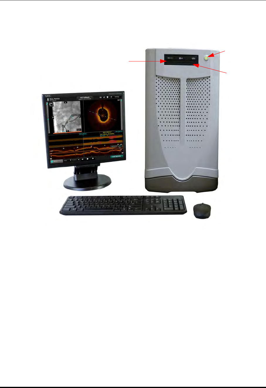
OPTIS Integrated System Cabinet and Control Room Components
Figure 1-1: OPTIS Integrated System Cabinet and Control Room Components
Control Room Monitor
ON/OFF
CD/DVD Tray
CD Eject
Power Switch/
Indicator
Button
Keyboard Mouse
System Overview
OPTIS Integrated System Components
ILUMIEN OPTIS System
Instructions for Use 1-5
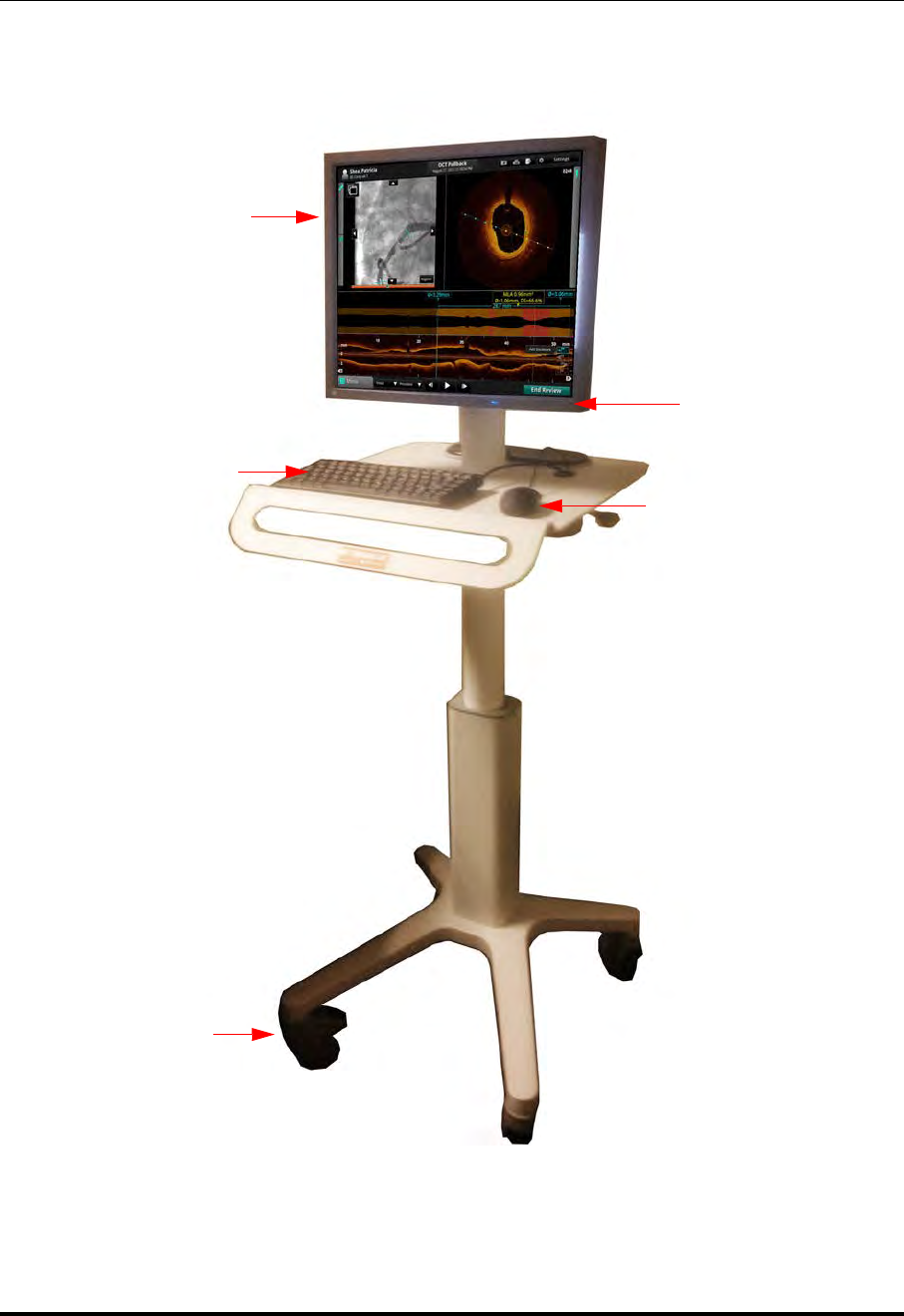
OPTIS INTEGRATED System - Mobile Workstation
Locking
Keyboard
Monitor
Mouse
Casters (4)
ON/OFF
Figure 1-1: OPTIS Integrated System Mobile Workstation
System Overview
OPTIS Integrated System Components
St. Jude Medical
1-6 Part Number ARTUS100109403
OPTIS Integrated System Table Side Controller
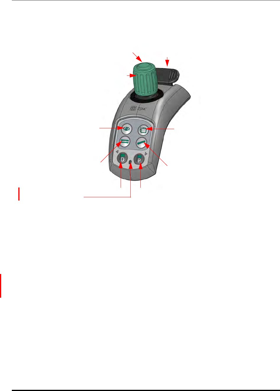
Table Side Controller: The TSC may be used to position the mouse cursor by moving the
Navigation Controller to left, right, up, or down. The Select button (on the top of the
Navigation Controller) functions as the left mouse button, and a twist of the Navigation
Controller functions as the mouse scroll wheel (twist left is scroll up and twist right is
scroll down).
Wireless Connectivity Indicator:
Blue = Connected
Yellow = No Connection
Navigation
Rail Clamp
Zoom
Features
Measurement
Auto Lumen
Profile
Distal Marker Proximal Marker
Table Side Controller
Select Button
Controller
Wireless
Connectivity
Indicator
System Overview
OPTIS Integrated System Components
ILUMIEN OPTIS System
Instructions for Use 1-7
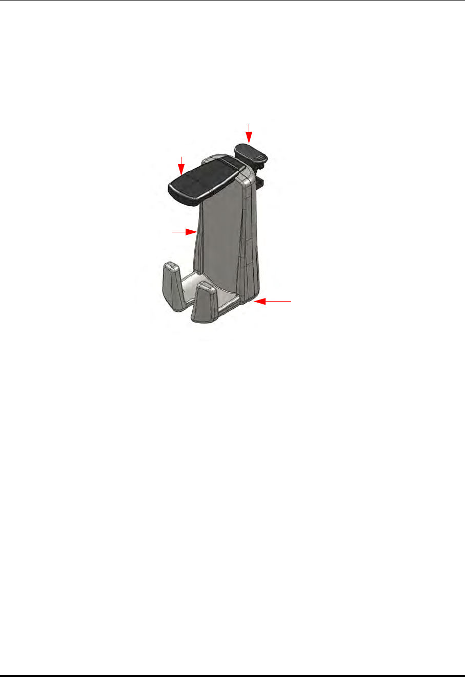
OPTIS Integrated System DOC Holster
DOC Holster
Dust Cover
Rail Clamp
Cable
Connections
System Overview
OPTIS Integrated System Components
St. Jude Medical
1-8 Part Number ARTUS100109403
OPTIS INTEGRATED Symbols
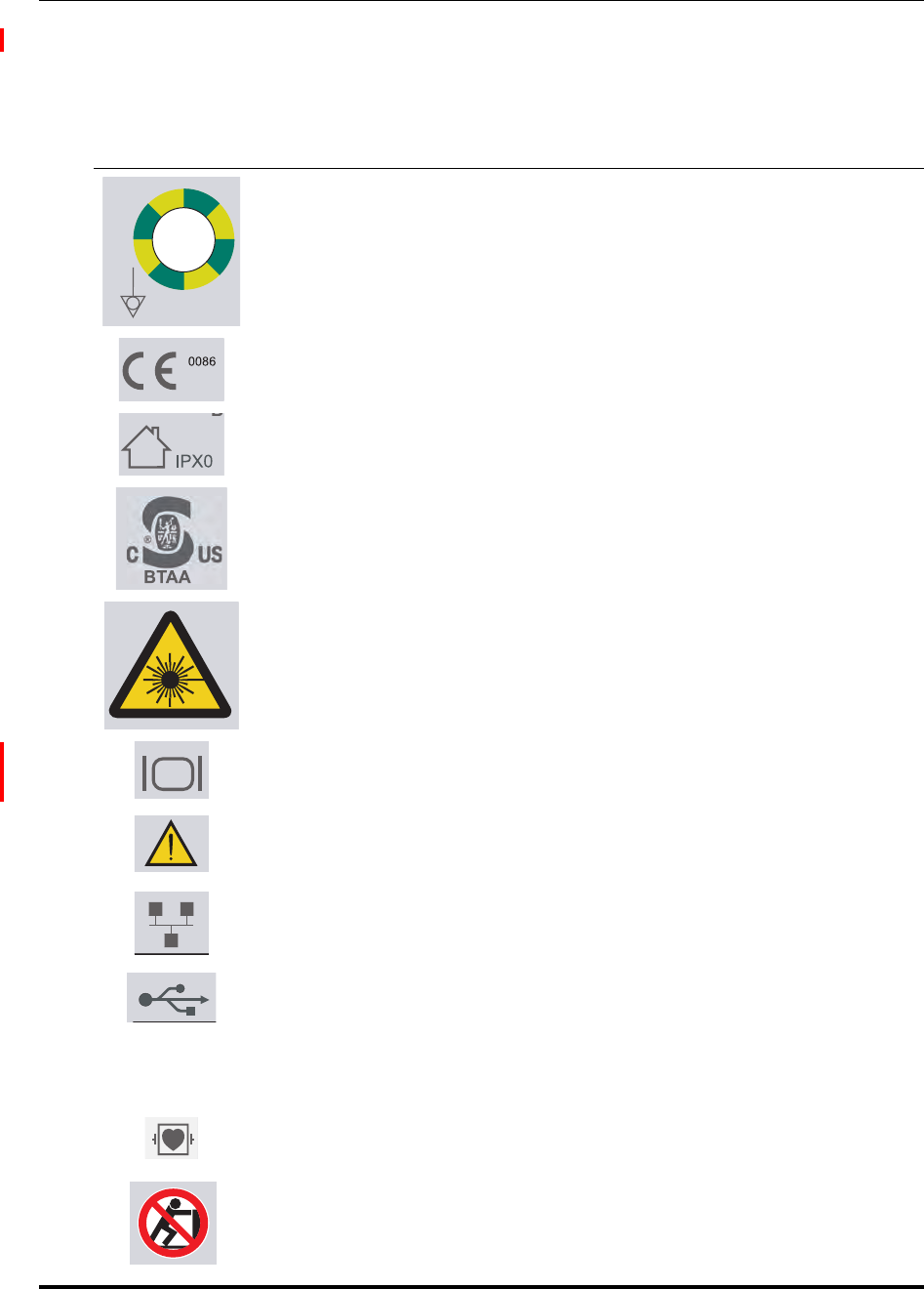
Before using the system, read these Instructions for Use carefully, including the identifi-
cation of symbols used on the equipment.
Table 1-1: Symbols Description
Equipotential Grounding Post - For a secondary ground connection between
equipment.
European Conformance, BSI Notified Body (British Standards Institution)
Indoor use only. No protection against ingress of water.
Curtis Straus NRTL
Laser hazard symbol - marks a device which produces visible and invisible
laser radiation.
VIDEO: For connection to an external boom monitor.
ATTENTION!: consult accompanying documents.
NETWORK: For connecting to a Remote DICOM Server through a network
(see the DICOM Setup menus in Chapter 10 “User Interface Reference”).
USB: For connection of external storage devices (see “USB Connected
Media” on page 8-2).
WARNING:If the USB device is being used in the patient vicinity it must
be port powered or it may compromise electrical isolation
and cause patient injury.
Type CF, defibrillator-proof. Suitable for all patient applications including
direct cardiac applications.
Do not push the system from the monitors or monitor support mount. See
“Moving the System” on page 11-4 for all safety instructions on moving the
system.

System Overview
OPTIS Integrated System Components
ILUMIEN OPTIS System
Instructions for Use 1-9
WARNING: All connections to the OPTIS INTEGRATED System must be made
through the System Connector Panel. Making connections directly to
internal components of the system may bypass isolation features and
compromise patient safety.
Date of Manufacture
FCC Identification Number
Industry Canada certification
Australian Communications and Media Authority supplier code number
Consult instructions for use
Interference may occur in the vicinity of this equipment
Disposal of the equipment must be in accordance with local laws.
Temperature Range (Shipping label)
Atmospheric Range (Shipping label)
Humidity Range (Shipping label)
Table 1-1: Symbols Description (continued)
500hPa
1060hPa
System Overview
The Drive-motor and Optical Controller (DOC)
St. Jude Medical
1-10 Part Number ARTUS100109403
The Drive-motor and Optical Controller (DOC)
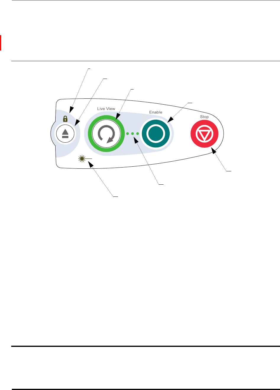
The Drive-motor and Optical Controller (DOC) provides bed-side control of the most
important OCT imaging functions. Refer to “Preparing to Acquire OCT Recordings” on
page 5-8 for Dragonfly Imaging Catheter connection details.
Table 1-2: DOC Controls
Lock LED • Off when the imaging catheter is not loaded.
•Blinking when loading or unloading the imaging catheter.
•On when the imaging catheter is loaded.
Unload Press to unload the imaging catheter.
Live View Press to switch between Standby View and Live View.
When the button is lit in green, the system is in Live View.
When the button is blinking, the system is enabled to begin a pullback recording.
NOTE: If the Recording Type is set to Stationary, this button does not blink.
Enable Press to Auto Calibrate or to Enable recording (if calibration is complete).
Stop Press to stop imaging catheter motion and turn off laser output.
Pullback
Motion LEDs •Off when the imaging catheter is stationary.
•Blinks during pullback.
Laser Emis-
sion Symbol Illuminated when laser output is on (whenever the system is in Live scanning mode).
Live View button
Lock LED
Unload button
Pullback Motion LEDs
Stop button
Enable button
Laser Emission Symbol
System Overview
The Wi-Box
ILUMIEN OPTIS System
Instructions for Use 1-11
The Wi-Box
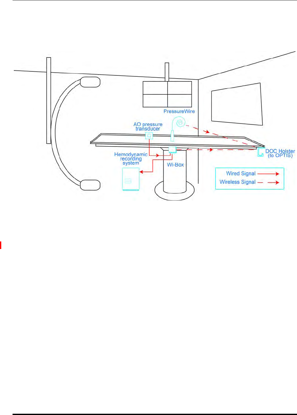
The Wi-Box is installed in your cathlab between your Hemodynamic Recording System
and the AO Transducer. The position of the Wi-Box in a cathlab is shown in Figure 1-2.
The wireless connection to your Wi-Box is made during setup for your procedure. See
“Setting up the Wi-Box with the OPTIS Integrated System” on page 4-3 for more infor-
mation.
Figure 1-2: Wi-Box in cathlab configuration

System Overview
Indications for Use and Intended Use
St. Jude Medical
1-12 Part Number ARTUS100109403
Indications for Use and Intended Use
The OPTIS INTEGRATED Imaging System with Dragonfly Imaging Catheter is intended
for the imaging of coronary arteries and is indicated in patients who are candidates for
transluminal interventional procedures. The Dragonfly Imaging Catheter is intended for
use in vessels 2.0 to 3.5 mm in diameter. The Dragonfly Imaging Catheter is not intended
for use in the left main coronary artery or in a target vessel which has undergone a
previous bypass procedure.
The OPTIS INTEGRATED Imaging System will further acquire radio frequency signal
outputs from both a distal intracoronary pressure transducer and a proximal aortic
pressure transducer to determine the physiological parameter, Fractional Flow Reserve
(FFR). The physician may use the FFR parameter, along with knowledge of patient
history, medical expertise and clinical judgment to determine if therapeutic intervention
is indicated.
CAUTION: The OPTIS INTEGRATED System is intended for use by appropriate
medical personnel who have received OPTIS INTEGRATED training.
St. Jude Medical and its employees cannot give instructions in the
interpretation or diagnosis of recordings and makes no attempt to do
so.
WARNING: Prior to use, please review the Instructions for Use supplied with the
Dragonfly Imaging Catheter and with the PressureWire for more
information.

System Overview
Contraindications
ILUMIEN OPTIS System
Instructions for Use 1-13
Contraindications
Use of the St. Jude Medical OPTIS INTEGRATED System is contraindicated where intro-
duction of any catheter would constitute a threat to patient safety.
Contraindications (listed alphabetically) include:
• Bacteremia or sepsis
• Major coagulation system abnormalities
• Patients diagnosed with coronary artery spasm
• Patients disqualified for CABG surgery
• Patients disqualified for PTCA
• Severe hemodynamic instability or shock
• Total occlusion
• Large thrombus
• Acute renal failure
NOTE: The system has no patient alarm functions. Do not use for cardiac monitor-
ing.

System Overview
Warnings (OCT)
St. Jude Medical
1-14 Part Number ARTUS100109403
Warnings (OCT)
• Appropriate anticoagulant and vasodilator therapy must be used during the proce-
dure as needed.
• Observe all advancement and movement of the Dragonfly Imaging Catheter under
fluoroscopy. Always advance and withdraw the catheter slowly. Failure to observe
device movement fluoroscopically may result in vessel injury or device damage.
• Leave the guidewire engaged with the catheter at all times during use. Do not with-
draw or advance the guidewire prior to withdrawing the catheter.
• If resistance is encountered during advancement or withdrawal of the Dragonfly
Imaging Catheter, stop manipulation and evaluate under fluoroscopy. If the cause of
resistance cannot be determined or mitigated, carefully remove the catheter and
guidewire together.
• The catheter should never be forced into lumens that are narrower than the catheter
body or forced through a tight or heavily calcified lesion.
• The catheter should not be advanced through abnormally tortuous anatomy.
• When advancing or retracting a catheter with a minirail tip through a stented vessel,
the catheter may engage the stent between the junction of the catheter and guide-
wire, resulting in entrapment of catheter/guidewire, catheter tip separation, and/or
stent dislocation.
• Refer to the contrast media’s instructions-for-use for general warnings and precau-
tions relating to use of the contrast media.
CAUTION: Before creating an OCT recording, review Chapter 5 “Performing an
OCT Procedure” for additional warnings and cautions.

System Overview
Precautions (OCT)
ILUMIEN OPTIS System
Instructions for Use 1-15
Precautions (OCT)
• Safety and effectiveness have been established for the following patient population:
adult patients undergoing non-emergent percutaneous coronary interventions in
lesions with reference vessel diameters between 2.0 to 3.5 mm, which were not
located in the left main coronary artery or in a target vessel which has undergone
previous bypass procedures.
• All operators must be trained prior to using the OPTIS INTEGRATED System and the
Dragonfly Imaging Catheter.
• Only 100% contrast media is approved for human use.
• Store the catheter at ambient temperature in a dry location out of direct sunlight.
• Never attempt to attach or detach a catheter to the DOC while the “lock” LED is lit.
• Do not kink, sharply bend, pinch, or crush the catheter at any time.
• The catheter is for single use only. Do not reuse, re-sterilize, or reprocess.
• The catheter is sterilized by ethylene oxide and is intended for one time use only.
Non-pyrogenic. Do not use if the package is opened or damaged.
• After use, the catheter may be a potential biohazard. Handle and dispose of in
accordance with accepted medical practice and applicable laws and regulations.
• The catheter has no user serviceable parts. Do not attempt to repair or alter any part
of the catheter assembly as provided.

System Overview
Complications (OCT)
St. Jude Medical
1-16 Part Number ARTUS100109403
Complications (OCT)
The risks involved in vascular imaging include those associated with all catheterization
procedures. The following complications (listed alphabetically) may occur as a conse-
quence of intravascular imaging and may necessitate additional medical treatment includ-
ing surgical intervention.
• Acute myocardial infarction or unstable angina
• Allergic reaction to the contrast media
• Arterial dissection, injury, or perforation
• Cardiac arrhythmias
• Coronary artery spasm
• Death
• Embolism
• Thrombus formation

System Overview
Warnings and Precautions (FFR)
ILUMIEN OPTIS System
Instructions for Use 1-17
Warnings and Precautions (FFR)
CAUTION: Before beginning an FFR procedure, review the PressureWire Instruc-
tions for Use. Details of the PressureWire are covered in the Pres-
sureWire Instructions for Use and are not covered in this manual.
CAUTION: Patients with potential microvascular dysfunction and borderline
FFR values should be interpreted with caution, and management
strategies should be guided not only by pressure measurement, but
also by possibly supplementary clinical risk stratification and other
tests.
Connecting to External Equipment/Accessories
WARNING: When used in the patient environment, all equipment connected to the OPTIS INTEGRATED
System must meet the requirements for medical isolation according to the IEC 60601 safety standards.
Connection of equipment that does not follow relevant IEC standards (e.g. IEC 60601 series for medical
electrical equipment) may lead to patient injury or death.
CAUTION: No connections to other systems or components are to be made to the OPTIS INTEGRATED
System except through the Connector Panel. No connections are to be made through the Connector Panel
except as described in this manual.
In addition, all such combinations of systems shall comply with the standard IEC 60601-1-1, Safety
requirements for medical electrical systems. Any person who connects external equipment to the OPTIS
INTEGRATED system has formed a medical system and is therefore responsible for compliance of the system
with the requirements of IEC 60601-1-1. If in doubt contact a qualified technician. Only PressureWire and
Wi-Box are intended to be used with the OPTIS INTEGRATED System wireless receivers.
Mechanical Enclosure
WARNING: Do not use the OPTIS INTEGRATED System if it has been dropped or in another way exposed
to mechanical or electrical damage or if liquids have penetrated the housing, or the user or patient may be
exposed to electrical shock or faulty readings may appear. Contact your supplier for further action.
CAUTION: Ensure that all ventilation holes are unblocked or else system overheating and false readings
may occur.
Electrical
WARNING: The mains power remains switched on when the system is in STANDBY mode.
Avoid direct or indirect (e.g. via the operator) conductive connection between other electrical equipment
and the OPTIS INTEGRATED System. Conductive connection may cause leakage currents to induce ventric-
ular fibrillation. High frequency surgical equipment must not be used on a patient at the same time as Pres-
sureWire and the OPTIS INTEGRATED System.
Electronic Interference
CAUTION: Radio transmitting equipment, cellular phones and strong emission sources such as high fre-
quency surgical equipment shall not be used in the close proximity of the OPTIS INTEGRATED System since
this could influence the performance of the device.

System Overview
Warnings and Precautions (FFR)
St. Jude Medical
1-18 Part Number ARTUS100109403
Aortic Reference Pressure
CAUTION: Check that the monitor cables and AO adapter delivered with the OPTIS INTEGRATED System
interface are compatible with the cathlab system to be used. The Aortic Pressure Transducer (AO) should
be in accordance with ANSI/AAMI BP22-1994.
Once the lab monitor system has been zeroed, use only the OPTIS INTEGRATED System to calibrate the aor-
tic pressure transducer and PressureWire.
Pressure Averaging (Mean Setting)
CAUTION: Choice of excessively high number of heartbeats may result in insensitive pressure averaging
(noticeable when there is a short hyperemic plateau). Choice of excessively low number of heartbeats may
result in pressure averaging, which are overly sensitive to arrhythmia and pressure disturbances. An insen-
sitive or overly sensitive mean average of pressure may result in an incorrect FFR value.
Defibrillation
CAUTION: The OPTIS INTEGRATED System is a CF Class I equipment and protected against the effects of
a discharge of a defibrillator. PressureWire readings may be affected by defibrillation. Recalibrate Pres-
sureWire after defibrillation use.
Recording
CAUTION: The system may place the point of FFR at the wrong location due to abnormal heart beat or
artefact in Pa from flushing the guiding catheter. The responsible physician should confirm that the point
selected by the system is a valid point of FFR.
CAUTION: If the cursor position has been saved, the FFR value is changed accordingly.
CAUTION: Before creating an FFR recording, review Chapter 4 “Performing an
FFR Procedure” for additional warnings and cautions.
CAUTION: After use, the catheter may be a potential biohazard. Handle and dis-
pose of in accordance with accepted medical practice and applicable
laws and regulations.

ILUMIEN OPTIS System
Instructions for Use 2-1
System Setup 2
Positioning the System
WARNING: Failure to position the system components as described may lead to a
system tipping hazard or a pinching hazard, causing possible patient
or operator injury and damage to the system.
• Confirm that the OPTIS Integrated System Cabinet is on a level surface inside the
Control Room or X-Ray Room. Confirm that the Control Room Monitor, keyboard,
and mouse are located on the Control Room Table.
NOTE: The USB ports are located on the keyboard.
• Mount the Table Side Controller onto the operating table rail in a location that is
comfortable for the physician during the procedure.
• Position the optional OPTIS Integrated Mobile Workstation (if used) at the foot of
the patient table with the monitor facing the attending physician.
Care must be taken to ensure the Mobile Workstation is clear of any moving equip-
ment, including the angiography system. It is the responsibility of the attending
physician to ensure that collisions do not occur.
NOTE: Whenever the Mobile Workstation is used near moving equipment,
it is recommended that the wheels remain unlocked to allow the sys-
tem to roll if it is bumped.
• Ensure the power cord and any other connections to the Mobile Workstation are
routed to prevent a tripping hazard. Ensure that the main power switch and power
plug can be accessed at any time during the procedure.

System Setup
Connecting Your System
St. Jude Medical
2-2 Part Number ARTUS100109403
Connecting Your System
System Connections
To connect the Mobile Workstation to power, plug the power cord into a grounded elec-
trical outlet. There is no Main Power Switch on the Mobile Workstation. The System
Cabinet and Monitors are normally always connected to power.
Powering On and Shutting Down Your System
Make sure the power cords are connected to the System Cabinet, optional Mobile Work-
station (if used), and control room monitor and they are plugged into grounded electrical
outlets. For detailed information on electrical requirements, see “Making Proper Electri-
cal Connections” on page 11-6.
WARNING: Never use a converter adapter to plug the three-pronged AC plug into
a two-pronged, ungrounded wall outlet. Doing so may result in electric
shock to the patient or operator and damage to equipment.
System Setup
Powering On and Shutting Down Your System
ILUMIEN OPTIS System
Instructions for Use 2-3
Power On System Cabinet
To power on your System Cabinet:
1. Confirm that all monitors are powered by observing that the appropriate power
indicators are lit. See “Monitor Setup” on page 2-6 for details.
2. Press the main power switch located at the upper-right side of the front of the cabi-
net to turn on system power (see Figure 1-1 on page 1-4).
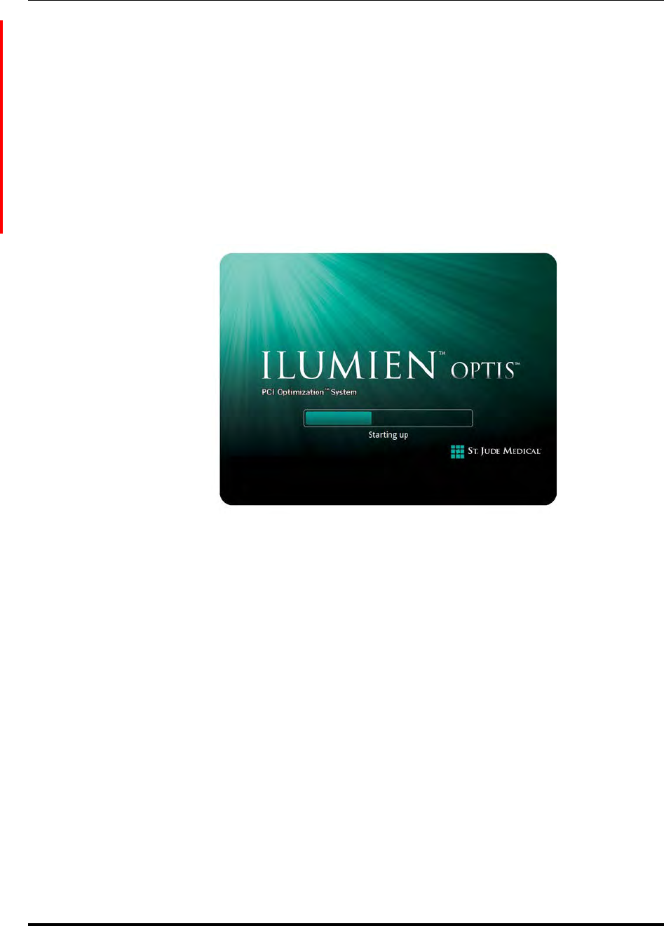
The system's Startup screen appears (Figure 2-1).
NOTE: The first time the software runs, the End User Licence Agreement (EULA)
displays. You must first read and agree to the EULA by checking the “I
agree to the terms of the EULA” checkbox in order to proceed.
NOTE: Once the system is turned on and the System Display is being shown, you
may need to adjust the monitor’s brightness and contrast as described in
“Monitor Setup” on page 2-6.
Figure 2-1: Startup Screen
System Setup
Powering On and Shutting Down Your System
St. Jude Medical
2-4 Part Number ARTUS100109403
Shut Down
CAUTION: Do not unplug from AC power or turn off main power until the shut-
down is complete, the screens turn black, and the monitor LEDs turn
amber. Disconnecting from AC power before the shutdown is com-
plete may damage the system.
NOTE: Use the Shutdown button at the top of the screen to shut down the system.
Use of the ON/OFF switch is not recommended to shut down the system.
To shut down the system:
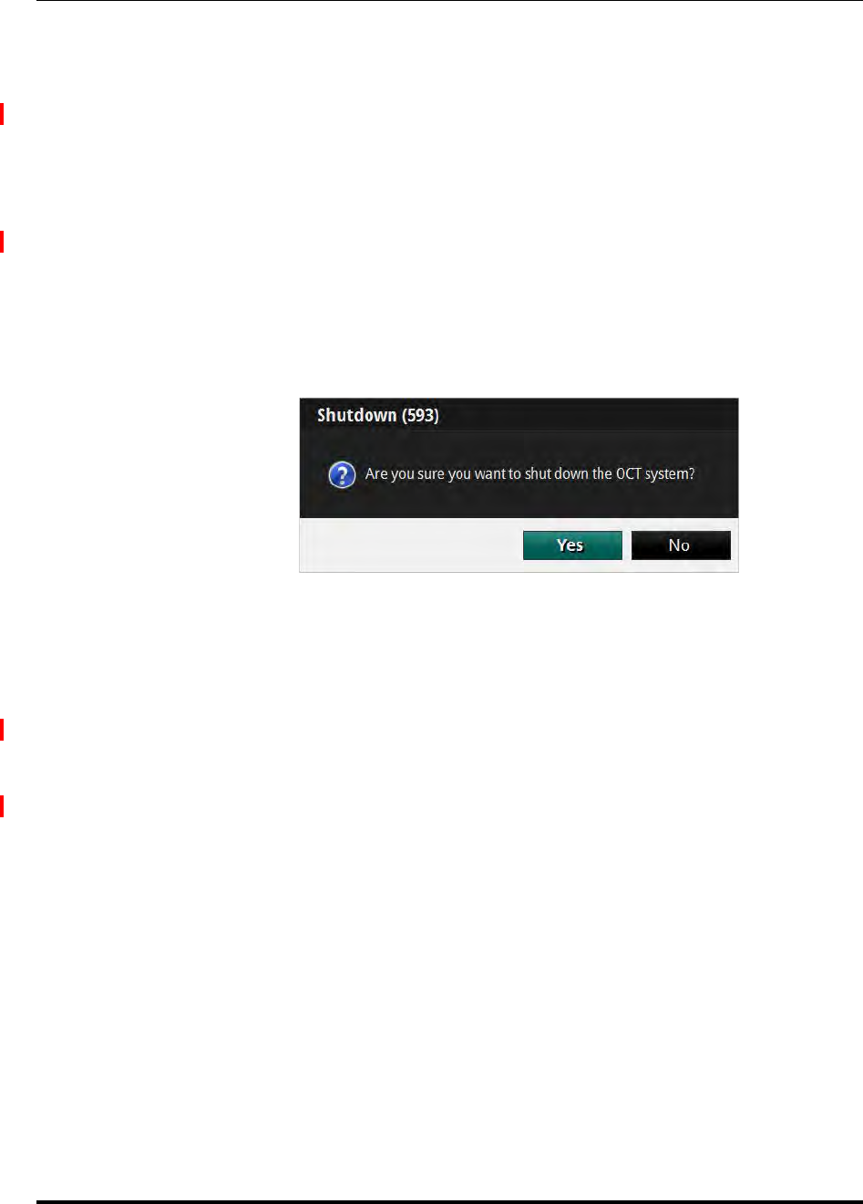
1. Click the Shutdown button located at the top of the screen. The system's Shutdown
menu appears (Figure 2-2).
2. Click Yes to begin the system shutdown, or No to continue using the system.
If you choose Yes, the computer begins the system shutdown. After 15 seconds, the
screens turn black, the monitor LEDs turn amber, and the system enters standby
mode.
3. After the screens turn black and the monitor LEDs turn amber, press the main
power switch at the base of the cart to turn off system power.
4. If necessary, disconnect the power cord from AC power.
Figure 2-2: Shutdown Menu

System Setup
FFR Settings
ILUMIEN OPTIS System
Instructions for Use 2-5
FFR Settings
NOTE: To access the full FFR Settings menu, you must be in the process of mak-
ing an FFR recording, and have selected a room for the FFR procedure.
1. Click the Settings button at the top of the screen.
The FFR Settings menu opens.
2. Confirm that the FFR settings are correct for this patient.
•Pressure Scale: Changes the vertical scale of the pressure waveform display.
The default setting is 0-200 mmHg.
•Sweep Speed: Changes how fast the screen is updated and the level of detail
visible to the user. A high number is suitable when a detailed picture of the
tracings is required. A low number is suitable when displaying slow changes,
for instance during intravenous infusing and pullback. The default setting is
Normal.
•Mean Filter Length (Beats): Changes the time over which the mean pres-
sure value is calculated. The adjustments are made by selecting the mean cal-
culation filter length, measured in number of heartbeats. The default setting is
3 heartbeats.
CAUTION: Choosing a high number of heartbeats makes the pressure
averaging slower and less sensitive to artifacts, but may
also result in overly insensitive averaging which is notice-
able when there is a short hyperemic plateau. Choosing a
low number of heartbeats makes the pressure averaging
faster and more sensitive to pressure changes, desirable
using a short hyperemic plateau, but it may also result in
an averaging overly sensitive to arrhythmia and pressure
disturbances.
NOTE: An insensitive or overly sensitive averaging of pressure may
result in an incorrect FFR value.
Changes in the Mean Filter Length setting are not applied to
previous FFR recordings.
When a new patient is selected, the Mean Filter Length set-
ting is reset to 3 heartbeats.

System Setup
Monitor Setup
St. Jude Medical
2-6 Part Number ARTUS100109403
Monitor Setup
The flat panel display monitors provided with the System have controls for brightness,
contrast, and other monitor functions. Each monitor’s display angle is adjustable.
Setting Monitor Functions
Refer to the Instructions for Use that accompanied your monitor.
Setting Monitor Position
The angle of the flat panel monitor should be set to eliminate or minimize glare from sur-
rounding lighting. To optimize viewing:
1. Grasp the monitor firmly with one hand on each side of the screen.
2. Adjust the viewing angle by tilting the monitor.

ILUMIEN OPTIS System
Instructions for Use 3-1
Opening a Patient Record 3
CAUTION: Please note St. Jude Medical makes no representation or warranty
that use of the OPTIS INTEGRATED System complies with applicable
privacy, security and confidentiality laws, but encourages you to
assess your own risk as you use, disclose, control, process or transfer
patient health information with the OPTIS INTEGRATED System.
Opening a Patient Record
Select Patient Menu (Home Menu)
St. Jude Medical
3-2 Part Number ARTUS100109403
Select Patient Menu (Home Menu)
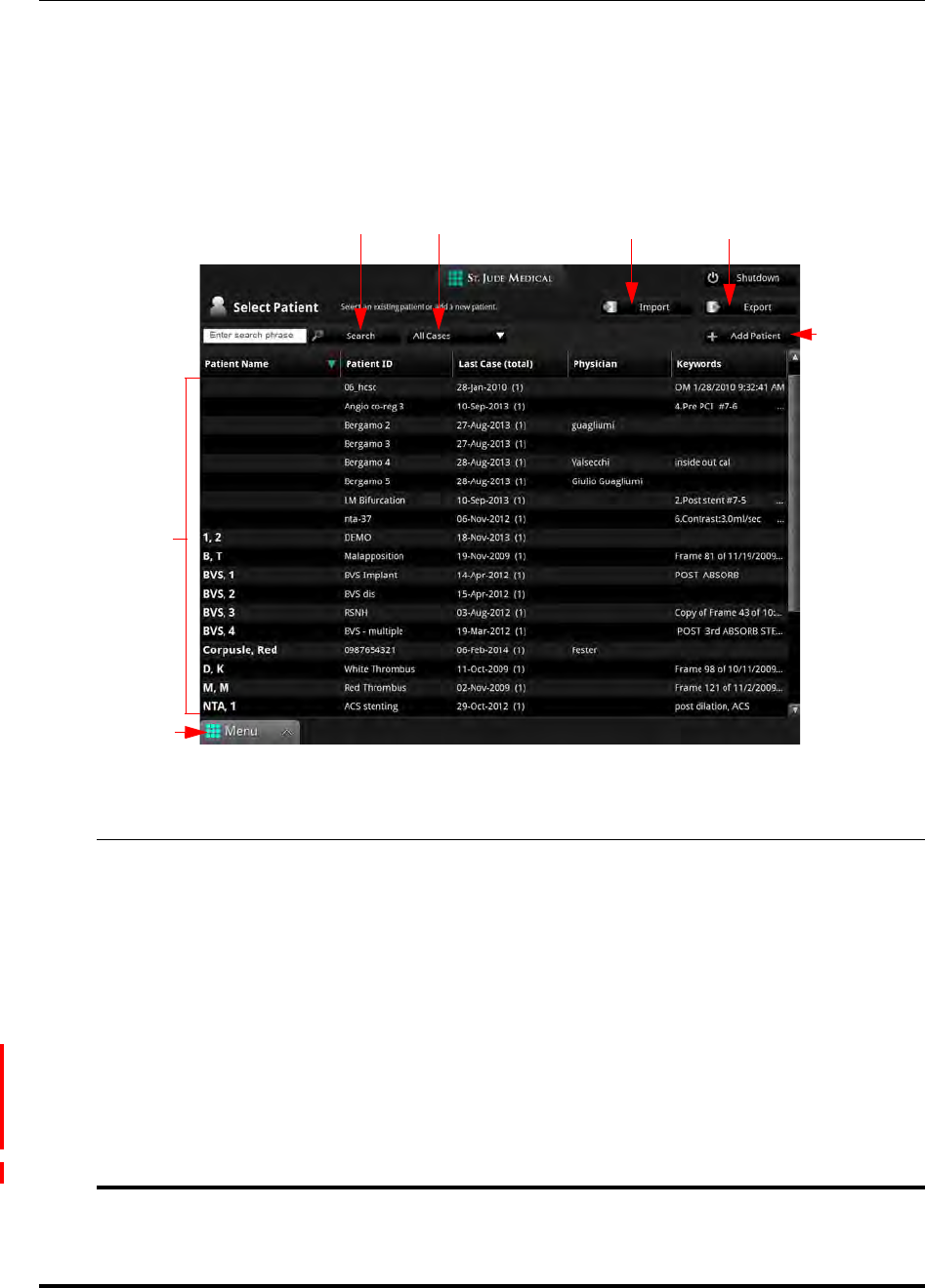
When the system is first started, the Select Patient menu is displayed (Figure 3-1). From
this menu, you can enter a new patient in the database, open an existing patient, or import
a previous patient record.
Table 3-1: Select Patient Menu functions
ASearch button: Enter a term and click this button to search the patient database.
BCase Filter drop-down list box: Select ALL cases, OCT only, or FFR only.
CImport button: Click this button to open the Import menu.
DExport button: Click this button to open the Export Wizard.
EAdd New Patient button: Click this button to enter a new patient into the System data-
base.
FList of all existing patients in the system database. Click on a column header to
sort the patients according to data in that column. Scroll names with mouse
wheel (or twist Navagation Controller) as desired; single-click name to select
patient.
GMenu: Displays the context-sensitive menu.
Figure 3-1: Select Patient Menu
AD
B
F
C
E
G
Opening a Patient Record
Select Patient Menu (Home Menu)
ILUMIEN OPTIS System
Instructions for Use 3-3
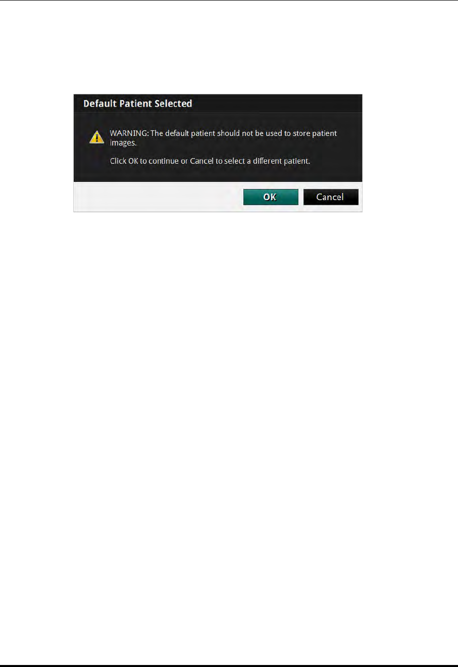
WARNING: If you select the default patient (“Patient, Default” in the patient list),
the system displays an alert (Figure 3-2). Do not use the default patient
to store patient images. Click OK to continue to use the default
patient, or Cancel to return to the Select Patient menu to select
another patient.
Figure 3-2: Default Patient Alert
Opening a Patient Record
Patient Summary Menu
St. Jude Medical
3-4 Part Number ARTUS100109403
Patient Summary Menu
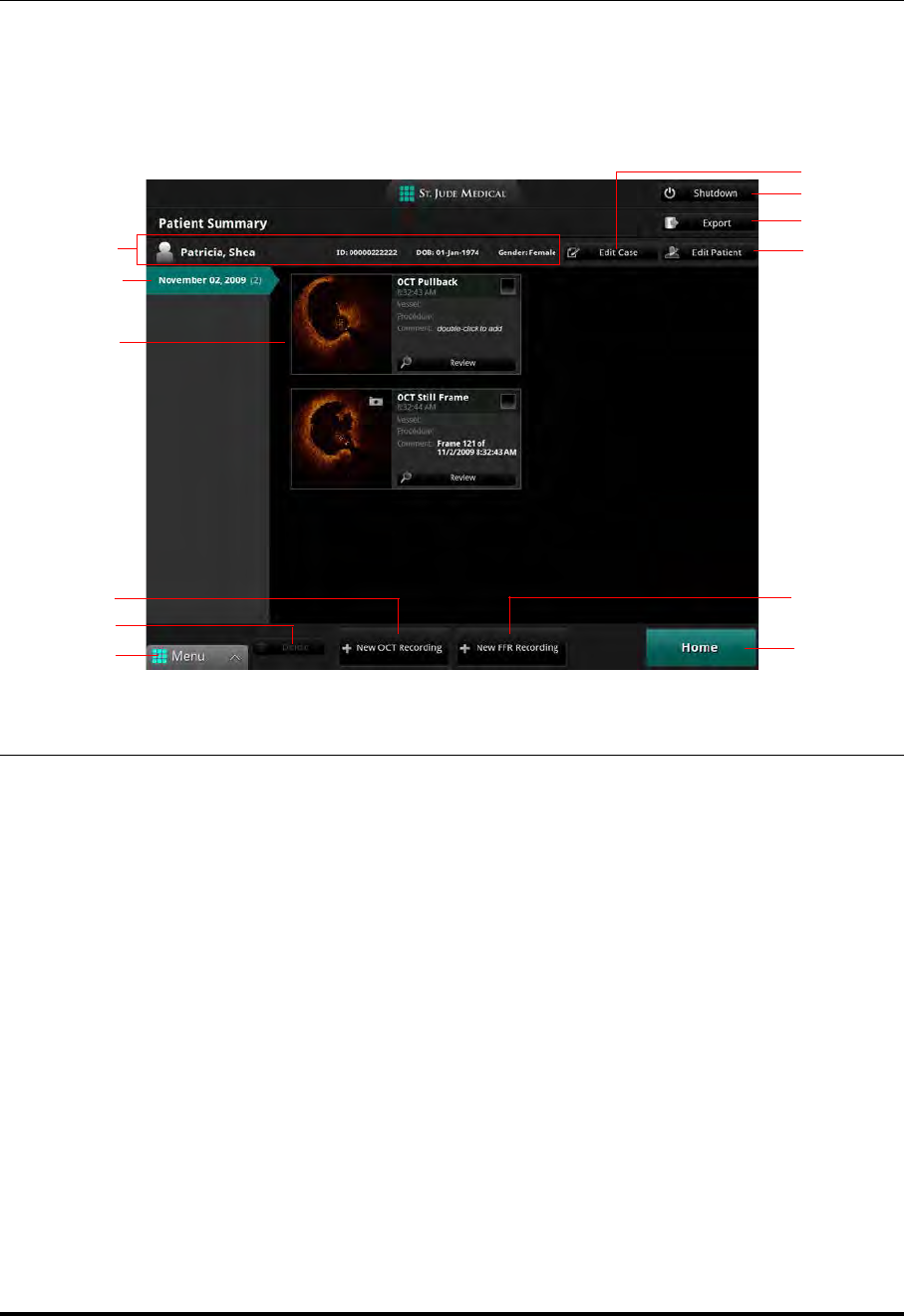
When you click on a patient name, the Patient Summary menu for that patient opens
(see Figure 3-3). If there are previous recordings for this patient, they are shown here,
sorted by date, with the most recent recordings at the top.
Table 3-2: Patient Summary Menu functions
APatient information, including name, ID, date of birth, and gender.
BEdit Case : Click this button to edit case information.
CShutdown : Click this button to begin the shutdown sequence for the system.
DExport : Click the Checkbox in one or more recordings to select them, then click the Export
button to open the Export Wizard.
EEdit Patient : Click this button to edit patient information.
FNew FFR Recording : Use this button to begin a new FFR recording for this patient.
GHome : Use this button to return to the Select Patient menu.
HMenu: Displays the context-sensitive menu. Provides access to the Setup menu.
IDelete : Check one or more recordings to select them, and click the Delete button to delete
them.
JNew OCT Recording : Use this button to begin a new OCT recording for this patient.
KGallery of existing recordings for this patient on the date highlighted at left. Double-click in
the Comment field to add a comment for that recording. Click the Review button under a
recording to open it.
Figure 3-3: Patient Summary Menu
A
C
D
I
H
E
F
G
J
L
K
B

Opening a Patient Record
Patient Summary Menu
ILUMIEN OPTIS System
Instructions for Use 3-5
LCase List (dates of recordings) for this patient. The list is sorted by date, with the most recent
recordings at the top.
Table 3-2: Patient Summary Menu functions
Opening a Patient Record
Entering New Patient Information
St. Jude Medical
3-6 Part Number ARTUS100109403
Entering New Patient Information
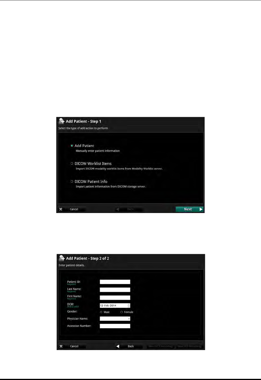
You can enter a new patient from the Select Patient menu.
1. In the Select Patient menu, select the Add Patient button. Click Next.
The Add Patient Wizard displays.
NOTE: You can also import patient information from a DICOM storage
server or worklist. See “Importing Patient Information From a
DICOM Worklist or Storage Server” on page 8-27.
2. Select Add Patient, then click Next.
The Add new patient menu opens (see Figure 3-4).
Figure 3-4: Add New Patient Menu

Opening a Patient Record
Entering New Patient Information
ILUMIEN OPTIS System
Instructions for Use 3-7
3. Enter the patient information as needed.
NOTE: You must enter Patient ID, First name, and Last name before you
can save the patient information.
4. Click New OCT Recording to save and begin a new OCT recording for this
patient, click New FFR Recording to save and begin a new FFR recording for this
patient, or Cancel to close the menu without saving and return to the Select Patient
menu. Click Back to return to the Add Patient Wizard.
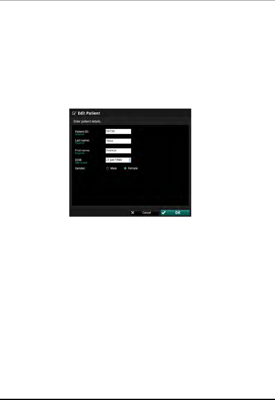
Opening a Patient Record
Editing Patient Information
St. Jude Medical
3-8 Part Number ARTUS100109403
Editing Patient Information
The patient information can be edited from the Patient Summary menu.
1. In the Select Patient menu, click on the patient.
The Patient Summary menu for that patient opens (see Figure 3-3).
2. Click the Edit Patient button.
The Edit Patient menu opens (see Figure 3-5).
3. Edit the patient information as needed.
NOTE: You must enter Patient ID, First name, and Last name before you
can save the patient information.
4. Click OK to save the changes, or Cancel to close the menu without saving.
Figure 3-5: Edit Patient Menu
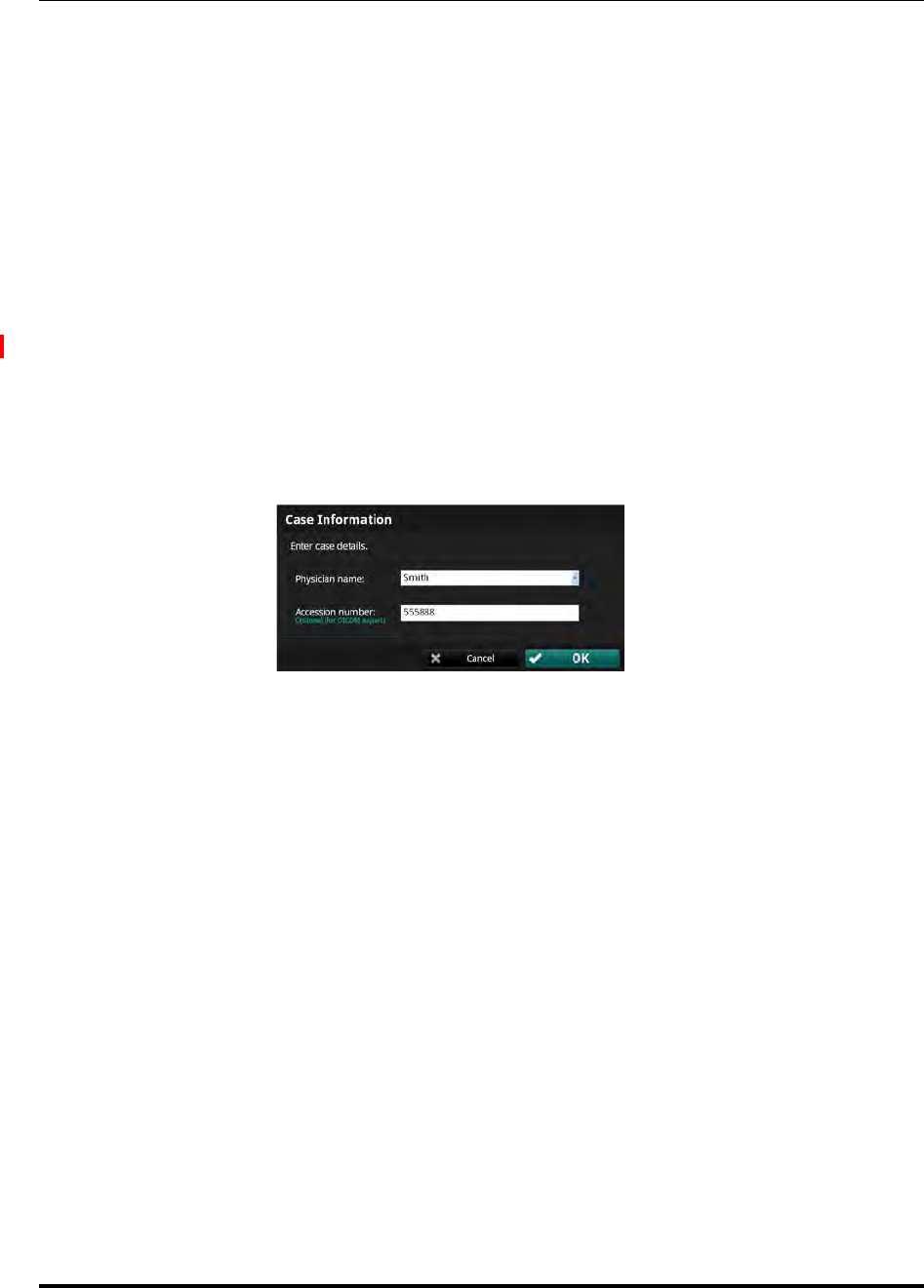
Opening a Patient Record
Editing Case Information
ILUMIEN OPTIS System
Instructions for Use 3-9
Editing Case Information
The physician name and accession number for a case can be edited from the Patient
Summary menu.
1. In the Select Patient menu, click on the patient.
The Patient Summary menu for that patient opens (see Figure 3-3).
2. Click on a case to select it.
NOTE: In the OPTIS INTEGRATED System, all recordings and still images
from the same date use the same physician and accession number.
3. Click the Edit Case button.
The Case Information menu opens (see Figure 3-6).
4. Edit the Physician name and Accession Number as needed.
5. Click OK to save the changes, or Cancel to close the menu without saving.
Figure 3-6: Case Information Menu

Opening a Patient Record
Importing a Patient Database
St. Jude Medical
3-10 Part Number ARTUS100109403
Importing a Patient Database
Previous C7 XR, ILUMIEN, and OPTIS INTEGRATED OCT and FFR recordings can be
imported into the system using the Import button on the Select Patient menu. For more
information on importing patient files or information, see “Importing Files from a
CD/DVD or USB” on page 8-20.
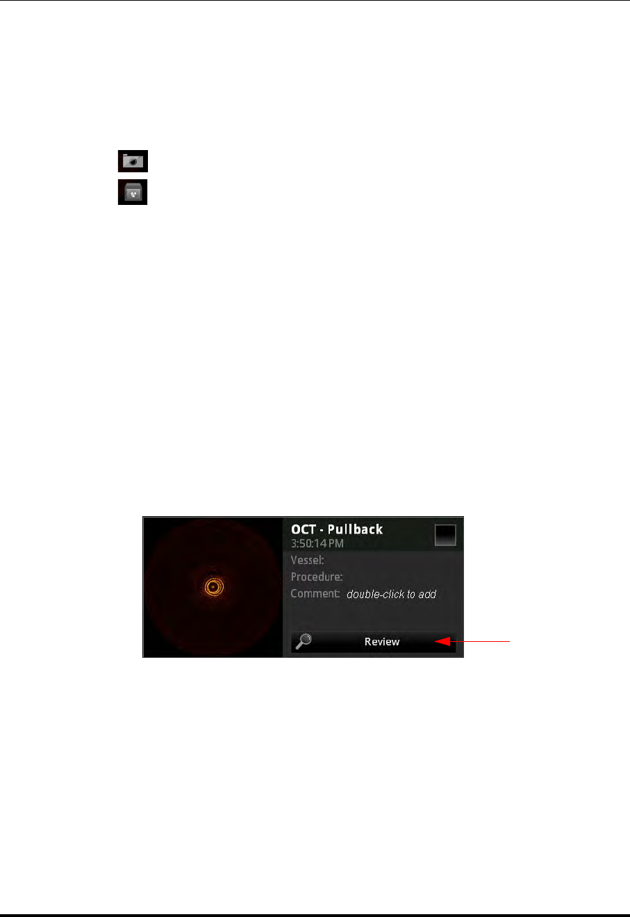
Opening a Patient Record
Opening a Saved Recording or Still Image
ILUMIEN OPTIS System
Instructions for Use 3-11
Opening a Saved Recording or Still Image
Each recording or still image has an entry in the Patient Summary menu. The entry
includes a timestamp and a thumbnail, and can display the Vessel, Procedure, and a
Comment, if added. The thumbnail adds icons to represent the status and content of the
file:
• A “camera” icon indicates a still frame from an OCT recording.
• A “safe” icon indicates that the file has been archived.
To review a saved recording or still image:
1. Open the Patient Summary menu:
•From the Select Patient menu, click on a patient’s name to select.
• From an OCT or FFR recording, click on the End Review button at the bot-
tom of the screen.
The Patient Summary menu for that patient opens (Figure 3-3 on page 3-4).
2. Click the date of the recording from the dates at the left of the menu.
All recordings and still images for that patient on that date are displayed.
3. Click on the Review button beneath the recording you want to open.
The recording or still image opens. Recordings play automatically.
Figure 3-7: Recording as shown in the Patient Summary Menu
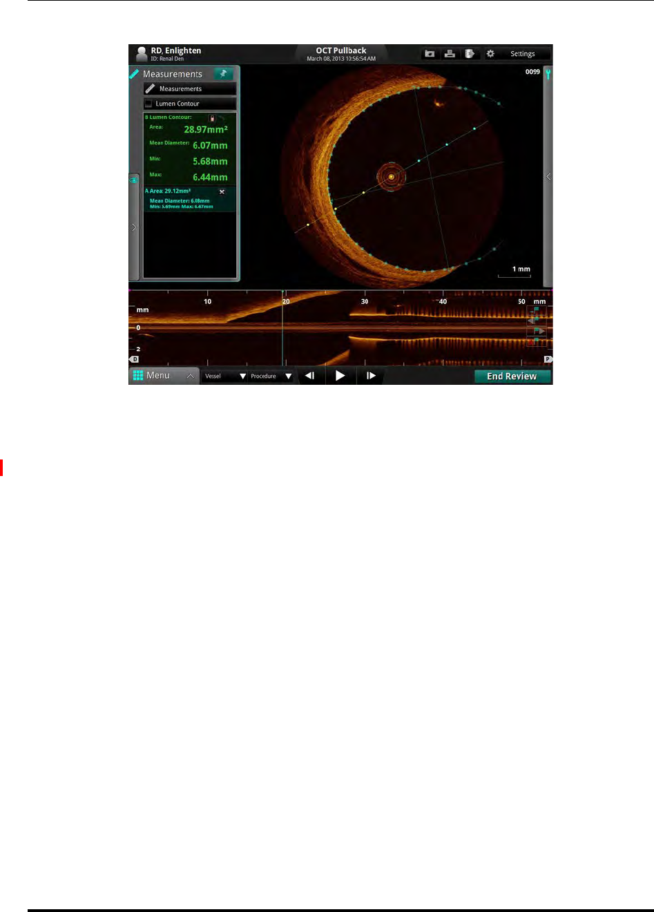
Opening a Patient Record
Opening a Saved Recording or Still Image
St. Jude Medical
3-12 Part Number ARTUS100109403
• To navigate an OCT recording, see “Playback Controls” on page 6-6; to nav-
igate an FFR recording, see “Reviewing an FFR Recording” on page 4-13.
• To add measurements and annotations to the OCT recording or still frame, see
Chapter 7 “Measurements and Annotations”.
• To export the entire OCT recording or individual frames, see Chapter 8
“Exporting, Importing, and Managing Files”.
4. To end the review and return to the Patient Summary menu, click the End Review
button.
Figure 3-8: OCT Review Screen
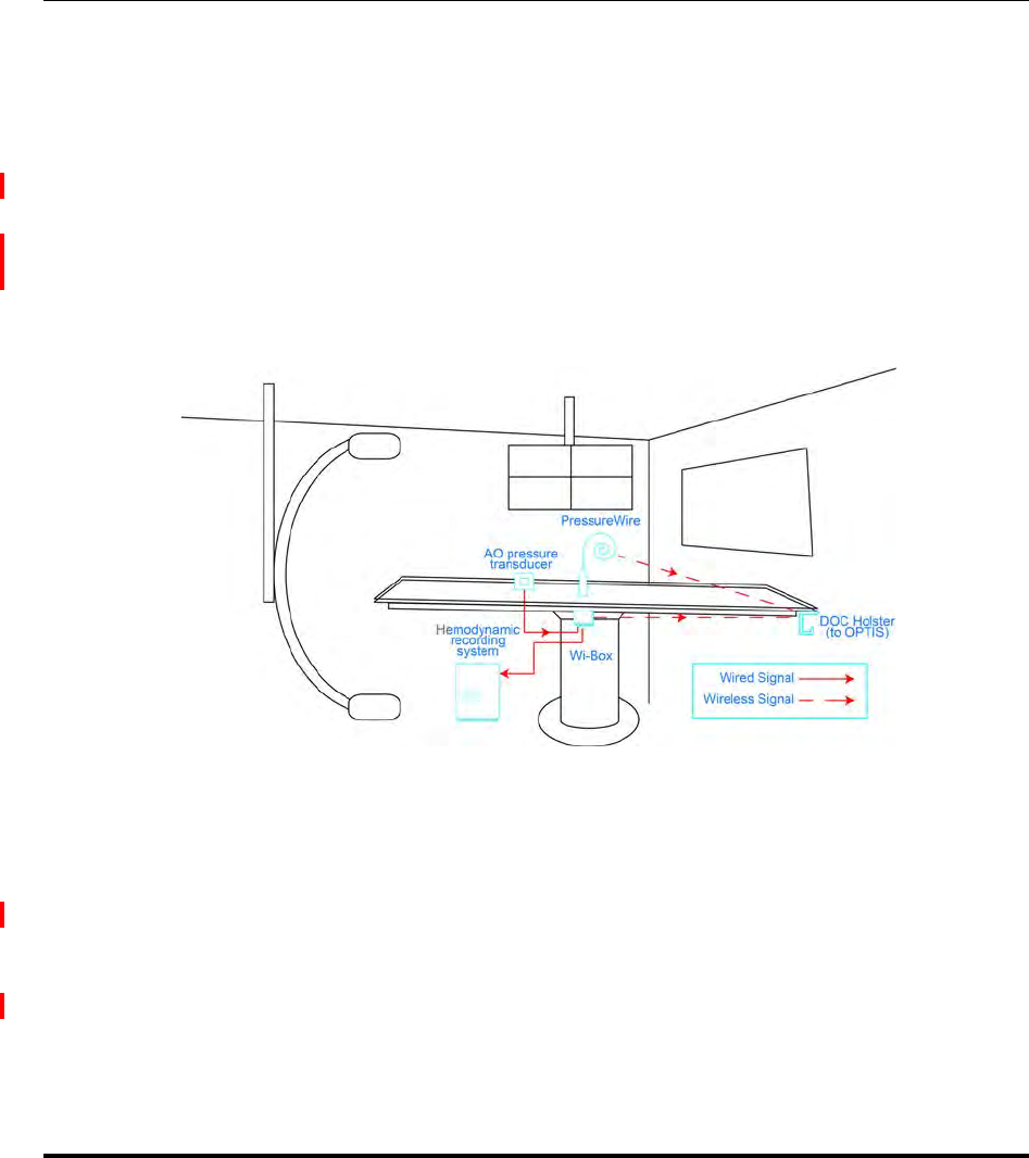
ILUMIEN OPTIS System
Instructions for Use 4-1
Performing an FFR Procedure 4
Overview
The FFR procedure requires up to two operators; a sterile operator and optionally, a
non-sterile operator. All steps requiring contact with the PressureWire must be performed
by the sterile operator. Any steps performed in direct contact with a keyboard or mouse
must be performed by the non-sterile operator.
A typical cathlab configured for FFR is shown below.
Required Material and Equipment
•OPTIS INTEGRATED System
• PressureWire
• Wi-Box, installed in each room where the OPTIS INTEGRATED System is to be used
to measure FFR
• Heparinized, physiologic saline solution, for hydrophilic catheter preparation
Figure 4-1: Cathlab with FFR
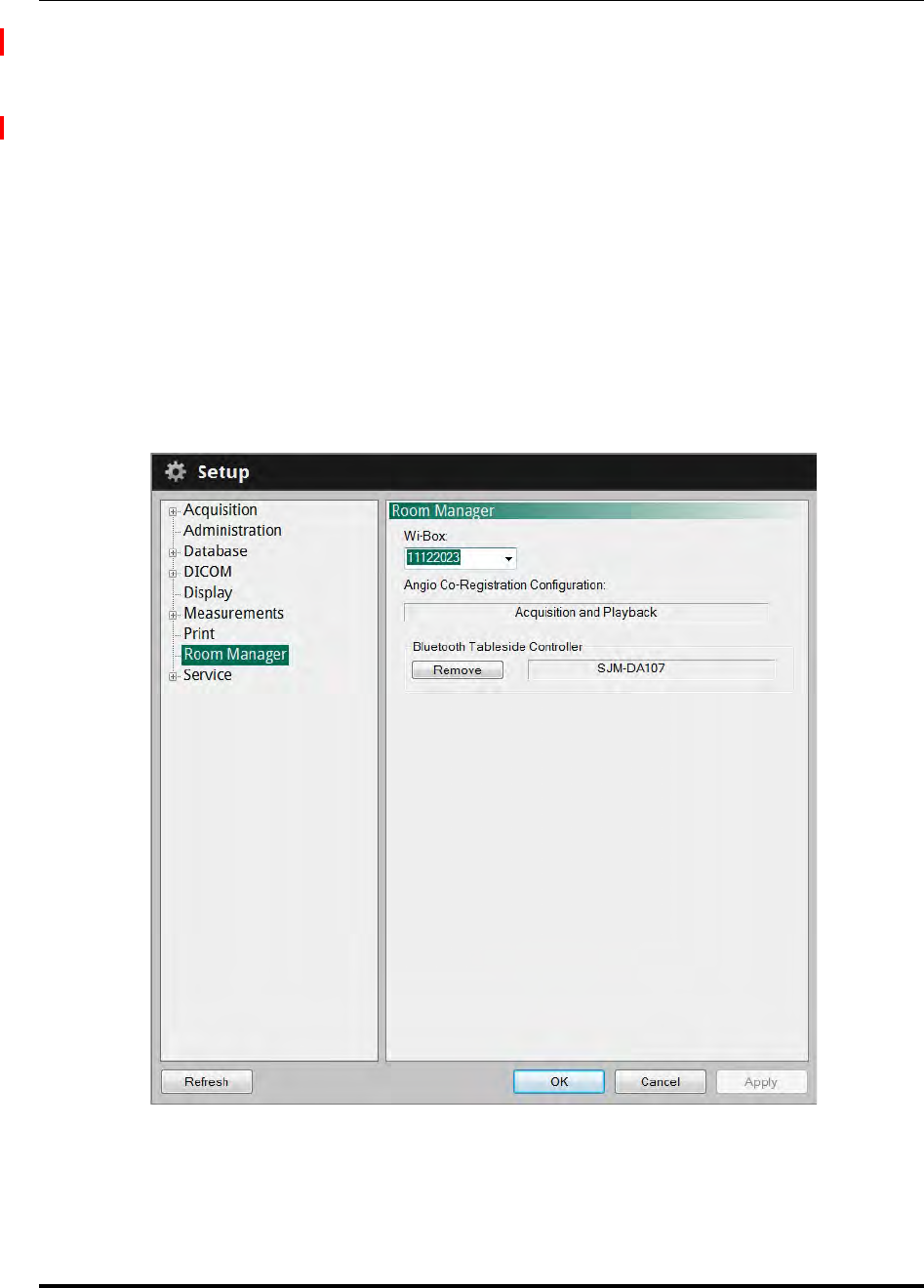
Performing an FFR Procedure
Setting up the Wi-Box with the OPTIS Integrated System
ILUMIEN OPTIS System
Instructions for Use 4-3
Setting up the Wi-Box with the OPTIS INTEGRATED System
The Wi-Box should be connected to your facility’s Hemodynamic Recording System at
installation. Complete the following steps to connect the OPTIS INTEGRATED System to
a Wi-Box for the first time .
1. Verify that the Wi-Box is powered-up by checking the power indicator light. Refer
to the installation instructions that came with your Wi-Box for further information.
2. From the Patient Summary screen or from the Select Patient menu, click on the
Menu button.
3. Click the Setup menu option.
4. Click on Room Manager. The Room Manager displays.
5. Verify that the Wi-Box Serial Number that appears in this dialog box matches the
Serial Number of the Wi-Box in your catheter lab.
Figure 4-2: Room Manager: Enter Room Information

Performing an FFR Procedure
Setting up the PressureWire
St. Jude Medical
4-4 Part Number ARTUS100109403
NOTE: Be sure to check the Wi-Box serial number. The Devices box will
auto-detect any active Wi-Box that is in-range. Ensure that the
Wi-Box serial number selected matches the Wi-Box device present
in the current room. (The serial number is visible on the front panel
of the Wi-Box.)
NOTE: The Wi-Box serial numbers can also be entered directly into the
Devices box.
NOTE: To change the Wi-Box selection, select the Wi-Box Serial Number in
the Room Manager dialog box, which enables the Remove button.
Then, click the Remove button to delete the current selection. Then,
follow the steps listed in “Setting up the Wi-Box with the OPTIS
Integrated System” on page 4-3 above.
Setting up the PressureWire
WARNING: Please review the Instructions for Use supplied with the PressureWire
for a complete list of warnings, cautions, and setup instructions.

Performing an FFR Procedure
Preparing to Record FFR
ILUMIEN OPTIS System
Instructions for Use 4-5
Preparing to Record FFR
WARNING: The heart rate and mean pressure values shown on the OPTIS INTE-
GRATED System are for reference only and are not intended to be used
as the primary display.
Start FFR recordings from the Patient Summary menu.
1. If necessary, enter the patient’s information. See “Entering New Patient Informa-
tion” on page 3-6.
NOTE: Patient information should be entered into the system and selected
for use before beginning a recording.
If you are entering a patient through the Add New Patient menu,
click the New FFR Recording button at the bottom of the menu, and
continue with Step 4 in this section.
2. In the Select Patient menu, click on a patient name.
The Patient Summary menu for that patient opens (Figure 3-3 on page 3-4).
3. In the Patient Summary menu, click the New FFR Recording button.
CAUTION: In order to connect to the correct AO source (Wi-Box) you must
select the room where the system is being used.
The first time you connect to a room, you must enter the room’s
information into the system. See “Setting up the Wi-Box with the
OPTIS Integrated System” on page 4-3 for more information.
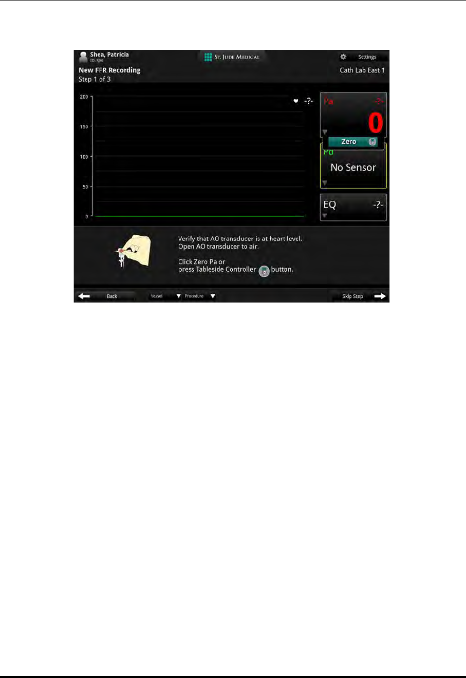
Performing an FFR Procedure
Preparing to Record FFR
St. Jude Medical
4-6 Part Number ARTUS100109403
The screen displays the main screen with the guidance message “Set AO transducer
height to heart level, then open AO transducer to air. Click Zero Pa.”
4. Position the AO transducer so that it is level with the patient’s heart.
NOTE: The AO transducer should remain level with the patient’s heart throughout
the procedure.
5. Open the AO transducer to air.
Figure 4-3: Set AO transducer height and open AO transducer guidance message
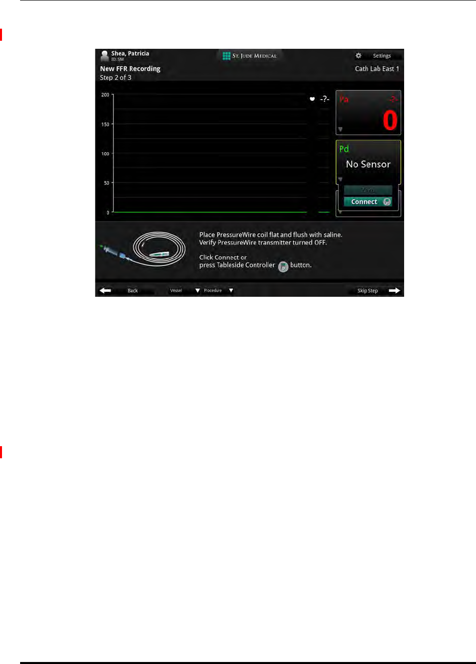
Performing an FFR Procedure
Preparing to Record FFR
ILUMIEN OPTIS System
Instructions for Use 4-7
6. In the Pa measurement box, click the Zero button, or on the Table Side Controller
press the Proximal Marker button.
7. Close the AO transducer.
8. Prepare the PressureWire in accordance with the PressureWire Instructions for Use
and the on screen prompts.
CAUTION: Do not use the PressureWire if there are any signs of damage.
9. In the Pd measurement box, click the Connect button, or on the Table Side Control-
ler press the Proximal Marker button.
NOTE: You have 60 seconds to make the connection between the Pres-
sureWire transmitter and the system. If necessary, click the Connect
button again after the 60 second time-out.
Figure 4-4: Flush PressureWire guidance message
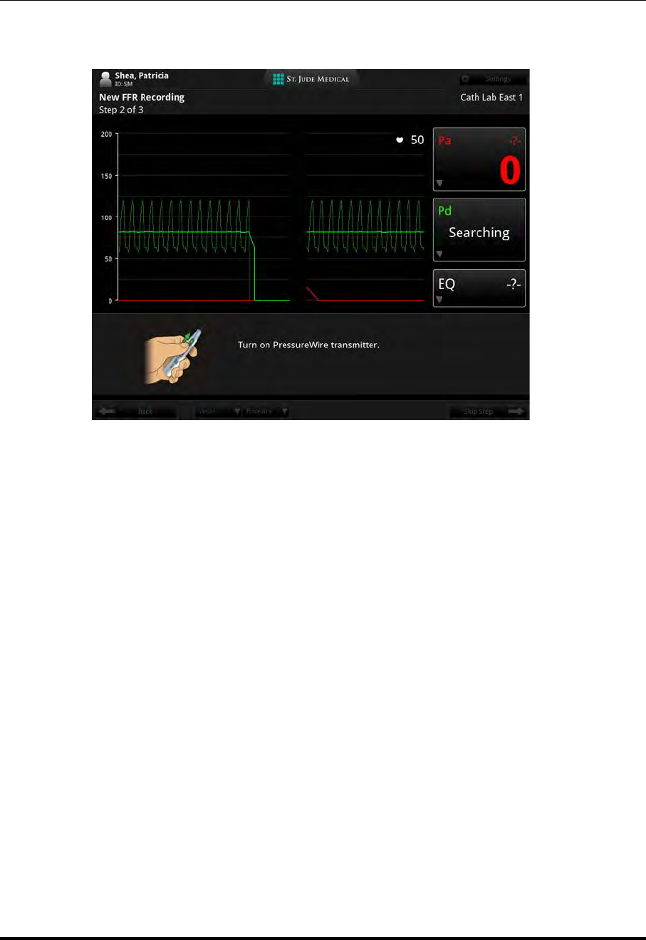
Performing an FFR Procedure
Preparing to Record FFR
St. Jude Medical
4-8 Part Number ARTUS100109403
The system is now looking for a PressureWire. The Pd measurement box shows the
message “Searching.”
CAUTION: Do not turn on more than one PressureWire while the system is
Searching/Connecting.
10. Turn on the PressureWire transmitter.
The Pd measurement box shows the message “Connecting” as the PressureWire
transmitter and the system make the wireless connection. Once the connection is
established, the Pd waveform appears (in green) in the graphical area of the display.
NOTE: If the system does not find the PressureWire after one minute, the
message in the Pd measurement box changes back to “No Sensor.”
Turn off the PressureWire and return to Step 9.
11. Remove the PressureWire from the plastic hoop.
12. Insert the PressureWire into the patient in accordance with the PressureWire
Instructions for Use.
Figure 4-5: Turn on PressureWire guidance message
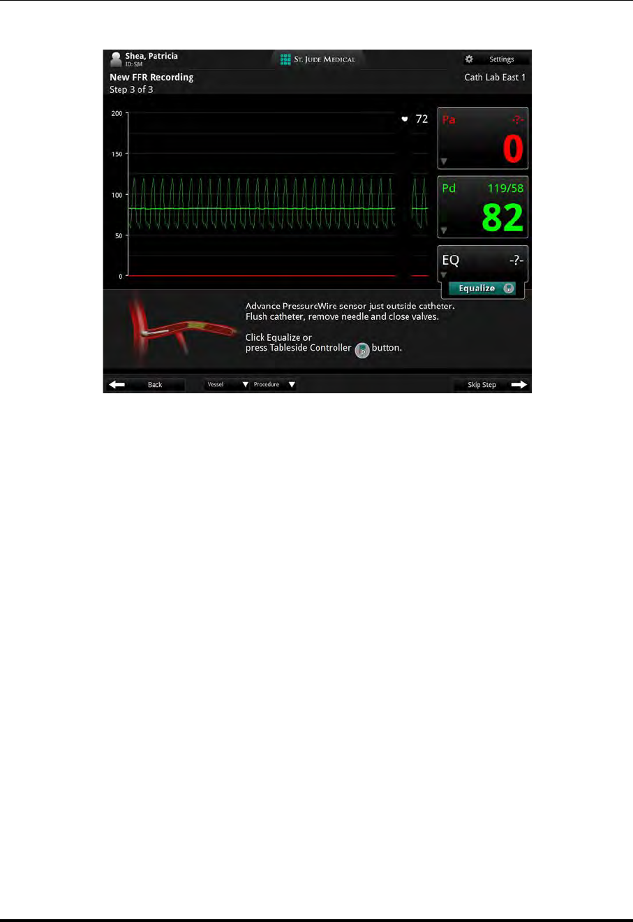
Performing an FFR Procedure
Preparing to Record FFR
ILUMIEN OPTIS System
Instructions for Use 4-9
The pressure from the AO transducer and PressureWire must now be equalized.
CAUTION: If the PressureWire is turned off or loses power at any point
after equalization, you must remove it from the patient and
re-zero it in its plastic hoop in heparinized saline before continu-
ing. See the PressureWire Instructions for Use for more informa-
tion on troubleshooting the PressureWire.
Figure 4-6: Advance PressureWire and Equalize guidance message

Performing an FFR Procedure
Preparing to Record FFR
St. Jude Medical
4-10 Part Number ARTUS100109403
13. Check the pressures displayed in the Pa and Pd measurement boxes (See Figure 4-6
on page 4-9). If the pressures are not equal, click the Equalize button (or on the
Table Side Controller press the Proximal Marker button) to equalize the pressure
reading between the AO transducer and the PressureWire.
The equalization offset value appears in the Equalization measurement box. The
offset is applied to the Pd pressure, to match the value of the Pa pressure.
CAUTION: If the equalization offset value is greater than or
equal to 30, or equal to or lower than -30, the sys-
tem displays an alert icon in the Equalization
measurement box. If the system displays this alert
icon, try the following to reduce the EQ value:
• Confirm the AO transducer is positioned at the same height
as the patient's heart and re-equalize.
• If the alert remains, remove the PressureWire from the
patient and re-zero it in its plastic hoop in heparinized saline.
CAUTION: To prevent incorrect measurement of the aortic pressure by the
guiding catheter, causing an incorrect FFR (Pd/Pa) calculation:
• Flush any contrast remnants from the guide catheter with
heparinized saline.
• The insertion tool must be pulled back out of the hemostatic
valve.
• The hemostatic valve must be closed during pressure mea-
surement.
NOTE: The equalization value (EQ) is reset when Pa or Pd is zeroed, or
when the PressureWire is restarted (turned on/off).
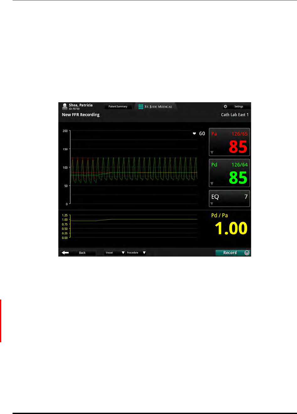
Performing an FFR Procedure
Recording FFR
ILUMIEN OPTIS System
Instructions for Use 4-11
Recording FFR
1. Confirm that the FFR settings are correct for the current procedure. See “FFR Set-
tings” on page 2-5 for more information.
2. With the PressureWire in position and equalized, advance it across the area to be
examined.
The bottom of the graphical area shows the Pd/Pa waveform, along with the Pd/Pa
ratio.
3. Induce hyperemia according to standard cathlab procedures.
4. Click the Record button (or on the Table Side Controller press the Proximal
Marker button).
A recording timer is displayed at the bottom of the screen. Click the Mark button
(or on the Table Side Controller press the Distal Marker button) to mark an instant
Figure 4-7: Pd/Pa waveforms equalizing
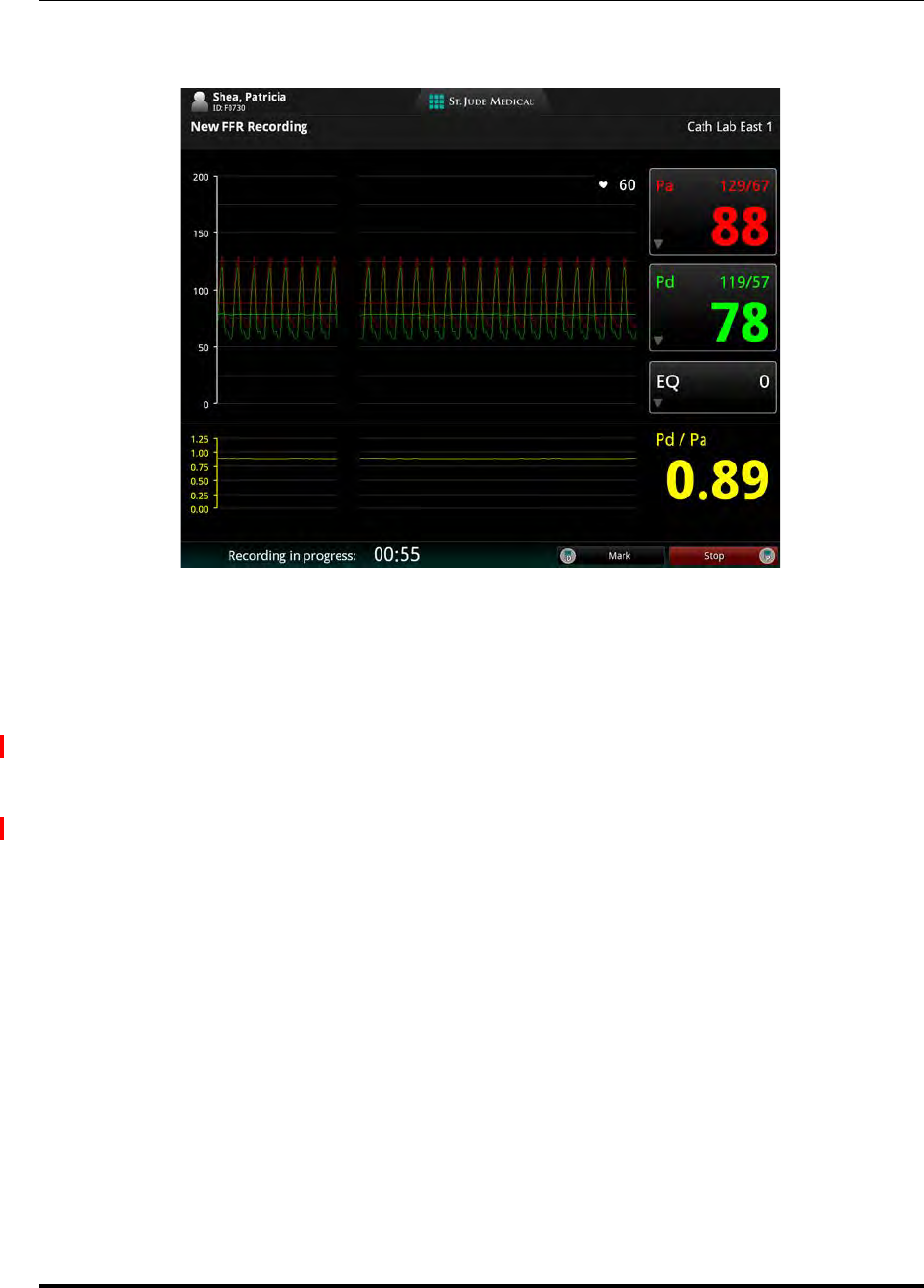
Performing an FFR Procedure
Recording FFR
St. Jude Medical
4-12 Part Number ARTUS100109403
on the recording for later review. A mark appears as a vertical white line on the
recording.
5. Record pressure until steady state maximum hyperemic condition is reached, until
the hyperemic effect begins to decrease, or until the physician decides to end the
recording. When finished, click the Stop button (or on the Table Side Controller
press the Proximal Marker button) to end the recording.
NOTE: During the recording, you can mark by clicking on the Mark button, or on
the Table Side Controller by pressing the Distal Marker button
NOTE: Turn off the PressureWire transmitter when it is no longer needed and
before disposal.
CAUTION: When the procedure is complete, handle the PressureWire and all
other disposables used during the procedure as potential biohazards.
Dispose of in accordance with accepted medical practice and all appli-
cable laws and regulations.
Figure 4-8: Recording
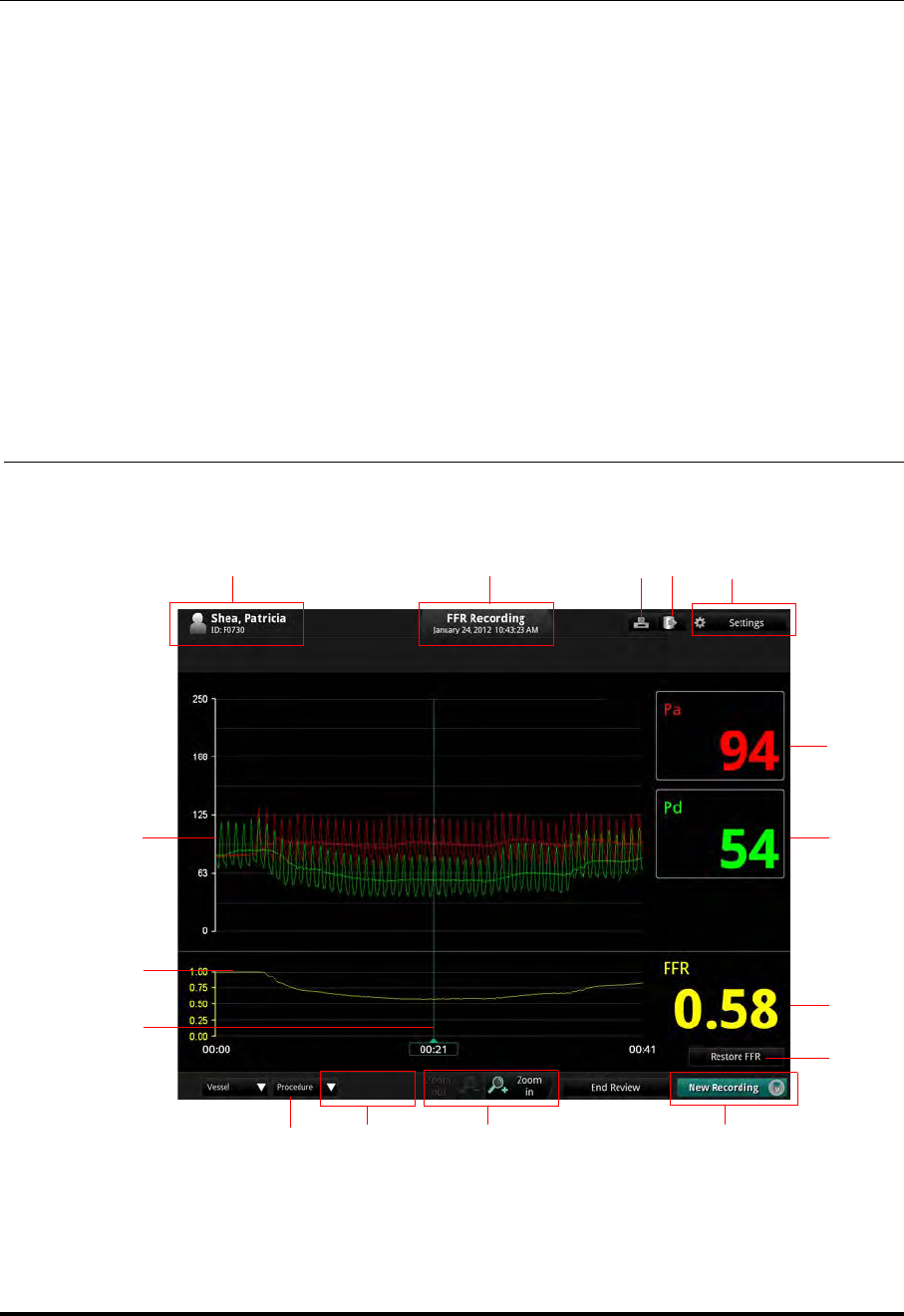
Performing an FFR Procedure
Reviewing an FFR Recording
ILUMIEN OPTIS System
Instructions for Use 4-13
Reviewing an FFR Recording
When the FFR recording opens, the entire recording is shown. By default, when the recording is
opened, the cursor is positioned at the point of the lowest Pd/Pa ratio.
WARNING: The system may place the point of FFR at the wrong location due to
abnormal heartbeats, for example artifacts in AO (Pa) caused by
flushing of guiding catheter or valve opening/closing. The physician
should always confirm that the point selected by the system is a valid
point for the calculation of FFR.
CAUTION: If you have zoomed in on a section of the recording, portions of the
waveform are not displayed (the recording extends off screen). The
physician should always review the entire unzoomed recording before
selecting the point for the calculation of FFR.
PG
F
H
O
KJ
N
ACE
B
L
M
D
Table 4-1: FFR Review Screen
I

Performing an FFR Procedure
Reviewing an FFR Recording
St. Jude Medical
4-14 Part Number ARTUS100109403
APatient name and ID.
See “Entering New Patient Information” on page 3-6 for more information.
BRecording date and time.
CPrint file to USB button: Available when a USB drive is connected. Click to print the FFR
recording file to a USB drive.
DExport button: Click to open the Export Wizard.
See Chapter 8 “Exporting, Importing, and Managing Files” for more information.
ESettings button: Click to open the FFR Settings menu.
See “FFR Settings” on page 2-5 for more information.
FPa measurement box. Mean Pa value at the cursor is displayed.
GPd measurement box. Mean Pd value at the cursor is displayed.
HThe FFR value at the cursor.
IRestore FFR button: After you have moved the FFR cursor during review; click on Restore
FFR to reset it to the location it was at when you opened the recording.
NOTE: Upon ending the FFR review, the marker will stay saved to the last point it was on.
If it is opened again, the reset button will be grayed out, until the FFR marker is
then again moved.
JEnd Review / New Recording : Click the End Review button to close this window and
return to the Patient Summary menu.
NOTE: While the system is connected to a PressureWire, the button Record appears here.
Click the New Recording button to close this review and begin a new FFR record-
ing.
CAUTION: When closing the recording, the current cursor position and correspond-
ing FFR value is saved. When the recording is re-opened, the cursor
appears at the saved position. The cursor may then be moved, and the dis-
played Pa and Pd pressures and FFR value change to reflect the new cur-
sor position.
KZoom in/Zoom out of the recording, centered on the cursor.
LProcedure list: Click to open a drop-down list of procedures to describe this recording.
MVessel list: Click to open a drop-down list of vessels to describe this recording.
NMove the cursor to read the Pa, Pd, and FFR value at any point in the recording.
OFFR waveform
PPa and Pd pressure waveforms

Performing an FFR Procedure
PressureWire Troubleshooting
ILUMIEN OPTIS System
Instructions for Use 4-15
PressureWire Troubleshooting
In case of low power in the PressureWire, the light on the PressureWire
unit flashes yellow, and a low battery indicator appears in the Pd mea-
surement box.
If there is a problem with your PressureWire, refer to the PressureWire
Instructions for Use for details.

Performing an FFR Procedure
PressureWire Troubleshooting
St. Jude Medical
4-16 Part Number ARTUS100109403

ILUMIEN OPTIS System
Instructions for Use 5-1
Performing an OCT Procedure 5
Overview
The OCT procedure requires two operators; a sterile operator and a non-sterile operator.
All steps requiring contact with the Dragonfly Imaging Catheter or the outside of the ster-
ile DOC cover must be performed by the sterile operator. All steps performed within the
sterile DOC cover or in direct contact with a keyboard or mouse must be performed by
the non-sterile operator.
Required Material and Equipment
•OPTIS INTEGRATED System
• C7 Dragonfly Imaging Catheter, Dragonfly Duo Imaging Catheter, or Dragonfly
OPTIS Imaging Catheter
• Sterile DOC Cover
• 3 mL purge syringe
• Contrast media indicated for coronary use, for purging and flush (allow 15 mL for
each run planned)
• 0.014 inch guidewire (with torque device if desired)
• Guide catheter (6 French, 0.068 inch ID or larger, with no side holes)
• Sheath introducer (to match guide catheter)
• Hemostatic Y-Adapter/Connector
• Heparinized, physiologic saline solution, for hydrophilic catheter preparation
• Power injector pump for coronary angiography or manual syringe (capable of
injecting 4.0 mL /sec for a total of 14 mL in 3.5 seconds)

Performing an OCT Procedure
Overview
St. Jude Medical
5-2 Part Number ARTUS100109403
OCT Imaging Overview
1. Position - Locate the Dragonfly imaging catheter relative to the target lesion/stent.
2. Purge - Clear blood from the catheter lumen, if present, using the attached 3 mL
syringe.
3. Puff - Inject a small amount (~ 4 mL) of contrast through the guide catheter to eval-
uate clearance.
If clarity is marginal, check the orientation of the guide catheter and target vessel.
4. Pullback - From Live View, select Enable to start the imaging process.
NOTE: In the left coronary system, guide catheter placement and orientation is
key to achieving good contrast flow. This is particularly true in the LCX.

Performing an OCT Procedure
OCT Operating Modes
ILUMIEN OPTIS System
Instructions for Use 5-3
OCT Operating Modes
During acquisition, the system is divided into Standby View and Live View.
•Standby View - The DOC is not rotating the imaging catheter. The last image
viewed through the catheter lens is shown on the display.
•Live View - The DOC is rotating the imaging catheter at low-speed, and is trans-
mitting images from the catheter lens to the display.
After the image has been recorded, see Chapter 6 “Reviewing OCT Recordings” for more
information on reviewing OCT recordings.
OCT Recording Types
The system can make two types of recordings: Pullback (Hi-Res or Survey) and Station-
ary. See “Setup - Acquisition Menu” on page 10-2 for more information.
NOTE: Hi-Res is a 54 mm pullback recording with double the frame density as
compared with Survey. Survey is a 75 mm pullback recording with stan-
dard frame density.
NOTE: The instructions in this manual are for Pullback recordings. Differences
for Stationary recordings are noted where applicable.

Performing an OCT Procedure
OCT Trigger Types
St. Jude Medical
5-4 Part Number ARTUS100109403
OCT Trigger Types
Automatic - The default setting in which the system triggers a pullback automatically
when a brief sequence of clear image frames are detected as a result of contrast injection.
If the flush injection is not detected within 15 seconds after being enabled, the system
returns to Live View.
Manual - The system does not perform a pullback until the operator clicks the Start Pull-
back button on the screen, or presses the Enable button on the DOC. If the flush injection
is not detected within 15 seconds after being enabled, the system returns to Live View.

Performing an OCT Procedure
Angio-Coregistration
ILUMIEN OPTIS System
Instructions for Use 5-5
Angio-Coregistration
Angio Co-Registration allows the user to align the angiography and OCT recording so
that OCT frames correlate with the corresponding angiography position. This functional-
ity allows the user to more easily determine their position in the OCT relative to the lesion
and assists in stent location and placement.
Setting up the OPTIS INTEGRATED System
1. Position the system for use. See “Positioning the System” on page 2-1.
2. Turn on the system. See “Power On System Cabinet” on page 2-3.
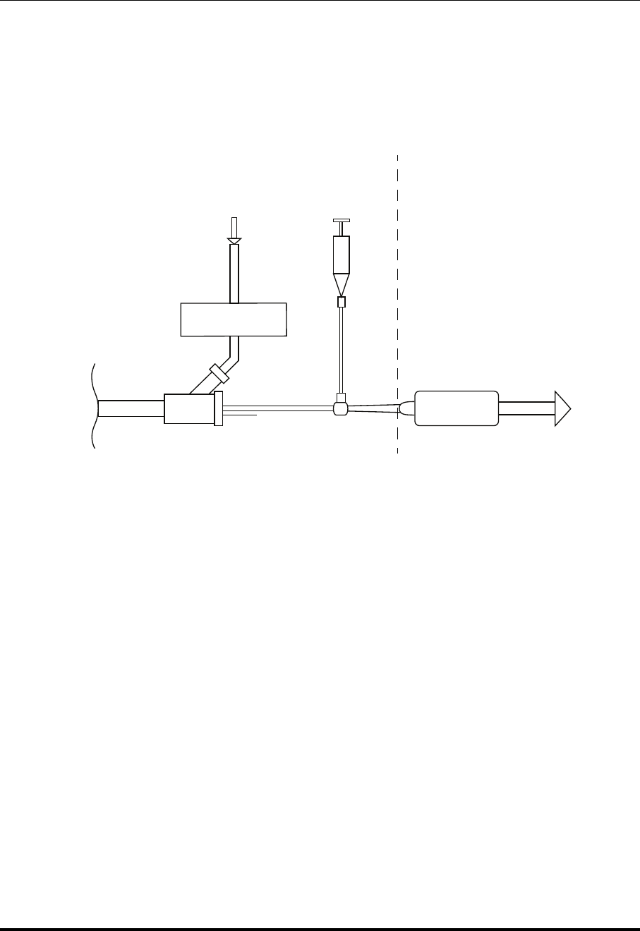
Performing an OCT Procedure
Setting up the DOC
St. Jude Medical
5-6 Part Number ARTUS100109403
Setting up the DOC
The DOC must be readied for use in the sterile environment.
CAUTION: Protect the exposed connector inside the DOC from fluids at all times.
Fluid contact can disable the DOC and require service.
Non-sterile Operator
1. With assistance from the sterile operator, place the DOC inside a sterile DOC cover.
2. Ensure the cover is extended over the DOC cable to its full length.
Sterile Operator
3. Connect the flush media (syringe or automated injector) to one port of the guide
catheter manifold (see Figure 5-1).
4. Use the following settings to prepare for flush delivery: (This step can also be per-
formed by Non-Sterile Operator)
• 4 ml/sec or less flush rate.
• 14 ml or less total flush volume.
• If using an automated injector, pressure limit 300 psi, or the nearest available
setting.
5. Purge all air from the tubing and manifold following standard practice.
Figure 5-1: DOC Connections
DOC
Patient
Manifold
Dragonfly
DOC
From
Contrast Injection Line
Guide
3 mL Syringe
Catheter To
OPTIS
Integrated
Cable
Imaging Catheter
Contrast Source Contrast Purge
Guidewire
Sterile Field Non-sterile Field
System

Performing an OCT Procedure
Setting up the Dragonfly Imaging Catheter
ILUMIEN OPTIS System
Instructions for Use 5-7
Setting up the Dragonfly Imaging Catheter
WARNING: Prior to use, please review the Instructions for Use supplied with the
Dragonfly Imaging Catheter for more information.
1. Inspect the packaging of the catheter for damage. Ensure that the catheter has not
passed its expiration date.
CAUTION: Do not use the catheter if the sterile packaging is compromised.
2. Using sterile technique, carefully remove the Dragonfly catheter from its sterile
package.
3. Carefully remove the catheter from the plastic hoop and examine it for visible dam-
age or defects.
CAUTION: Do not use the catheter if there are any signs of damage.
4. Moisten the distal segment of the catheter from the tip to approximately 100 cm
proximally using heparinized saline to ensure optimal performance of the hydro-
philic coating.
CAUTION: Use heparinized saline only.
5. Remove the cap from the sidearm luer and attach a 3 ml syringe filled with 100%
contrast.
CAUTION: Take care in handling the Dragonfly to prevent breaking the
fiber-optics within the catheter. Kinking and bending of the
catheter can cause damage. While connecting, ensure the proxi-
mal catheter segment is straight and aligned with the DOC.
Never attempt to connect and operate the catheter while the
catheter remains coiled within the hoop.

Performing an OCT Procedure
Preparing to Acquire OCT Recordings
St. Jude Medical
5-8 Part Number ARTUS100109403
Preparing to Acquire OCT Recordings
New OCT recordings are started from the Patient Summary menu.
1. If necessary, enter the patient’s information. See “Entering New Patient Informa-
tion” on page 3-6.
NOTE: Patient information should be entered into the system and selected
for use before beginning a recording.
If you are entering a patient through the Add New Patient menu,
click the New OCT Recording button (located at the bottom of Step
2 of the Add New Patient wizard), and continue with Step 4 below.
2. In the Select Patient menu, click on the patient.
The Patient Summary menu for that patient opens (Figure 3-3 on page 3-4).
3. In the Patient Summary menu, click the New OCT Recording button.
NOTE: If necessary, enter Physician name and Accession number for this
case, and click OK.
4. If Flush Medium was set to anything other than Contrast for the previous patient,
the setting is changed back to Contrast and an alert appears.
The system will ask you to confirm or choose another flush medium, then click OK
to close the alert. If you need to change the Flush Medium setting, see “Confirm
Recording Settings” on page 5-12.
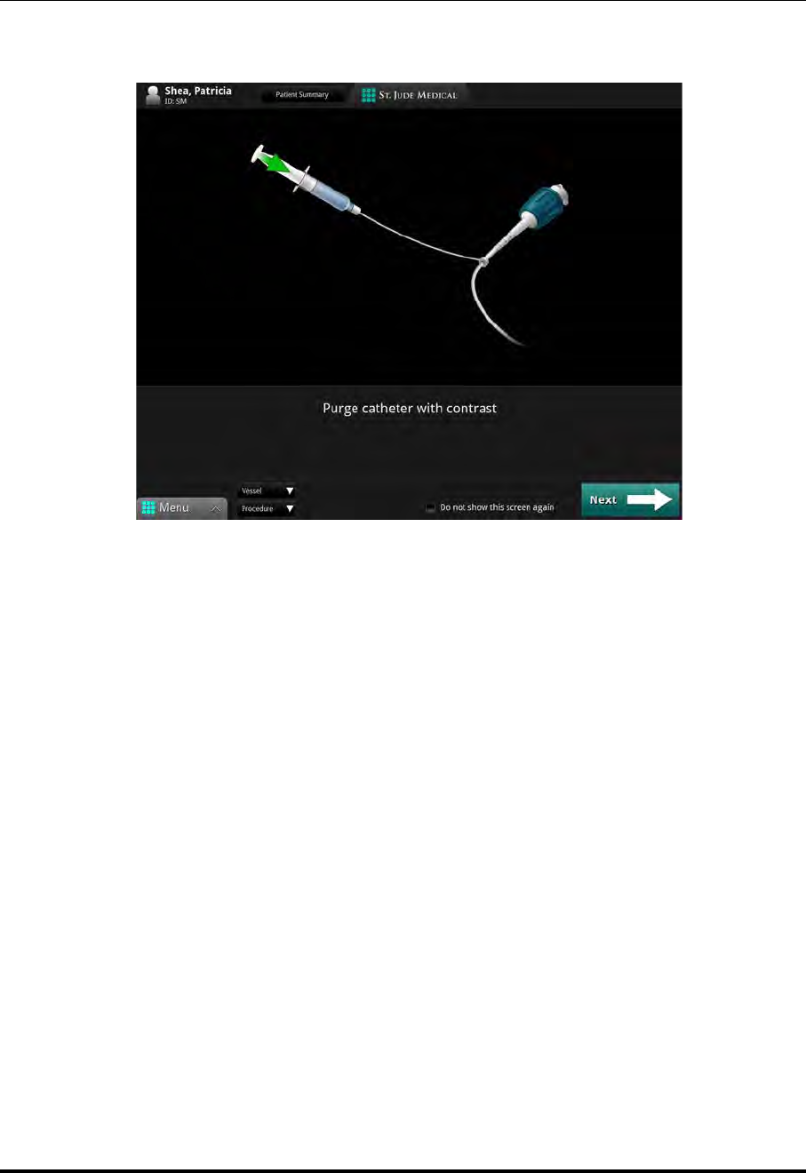
Performing an OCT Procedure
Preparing to Acquire OCT Recordings
ILUMIEN OPTIS System
Instructions for Use 5-9
5. The screen displays the guidance message “Purge catheter with contrast” (Figure
5-2).
NOTE: To prevent this guidance message from appearing, check the box next to
the message “Do not show this screen again.”
6. Purge the Dragonfly Imaging Catheter's lumen with 100% contrast media from the
3 ml syringe to remove all air from the catheter. Flush until 3-5 drops exit from the
catheter's distal tip. Do not remove the syringe from the catheter purge port after
flushing.
CAUTION: The catheter must be purged prior to connection to the DOC.
Figure 5-2: Purge Catheter guidance message
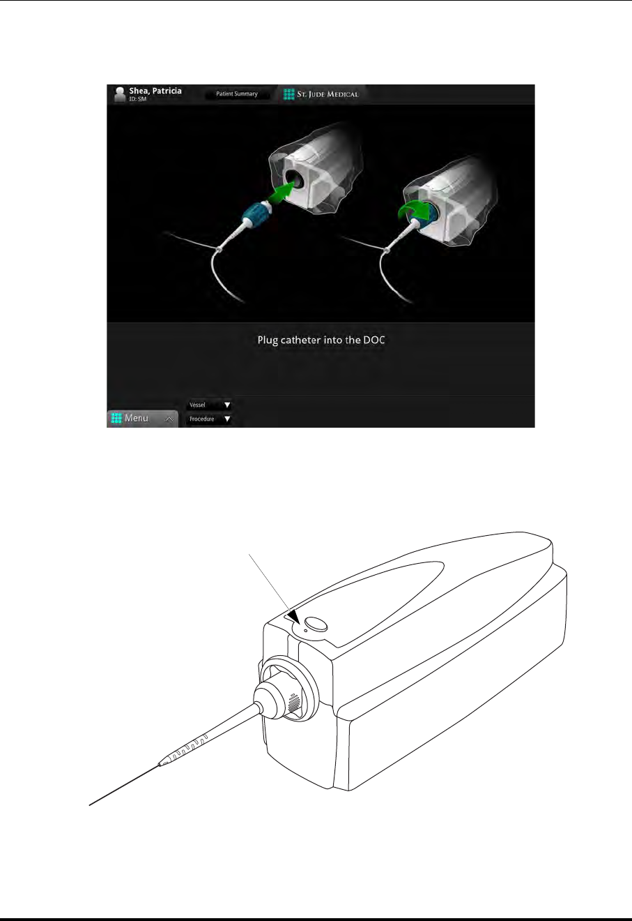
Performing an OCT Procedure
Preparing to Acquire OCT Recordings
St. Jude Medical
5-10 Part Number ARTUS100109403
7. Once the 100% contrast media has been injected, click the Next button.
The screen displays the guidance message “Plug catheter into DOC” (Figure 5-3).
8. Insert the hub of the catheter into the port of the DOC, and twist the hub clockwise
until secure (1/8 turn).
Figure 5-3: Plug Catheter into DOC Guidance Message
Figure 5-4: Dragonfly Catheter Connected to the DOC
Lock LED
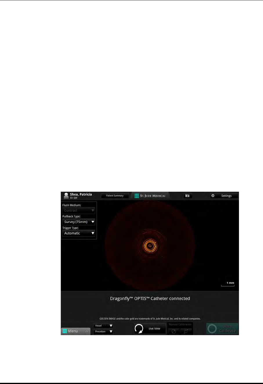
Performing an OCT Procedure
Preparing to Acquire OCT Recordings
ILUMIEN OPTIS System
Instructions for Use 5-11
CAUTION: Do not insert or remove the catheter while the DOC is scanning.
Do not attempt to disconnect the catheter from the DOC while the
“lock” LED is blinking as it could damage the catheter or the DOC.
The DOC's “lock” LED flashes and lights as the DOC automatically makes the
internal optical fiber connection, and the green Connecting imaging catheter
progress bar at the bottom of the screen completes.
NOTE: If the Connection Failure alert appears, unload the catheter (press
unload on the DOC) and try to load the catheter again. If this alert
appears again, replace the catheter.
NOTE: If the connection or initial calibration is stopped, the Connection
Cancelled alert is displayed. If this alert appears, unload the catheter
(press unload on the DOC), click OK, and try to load the catheter
again.
On screen, the size and position of the outer sheath of the catheter is adjusted with
respect to the calibration marks (see Figure 5-5).
When the connection and initial calibration are complete, the confirmation mes-
sage, Catheter connected, appears. The system goes into Standby View.
Figure 5-5: Catheter Connected, Initial Calibration done
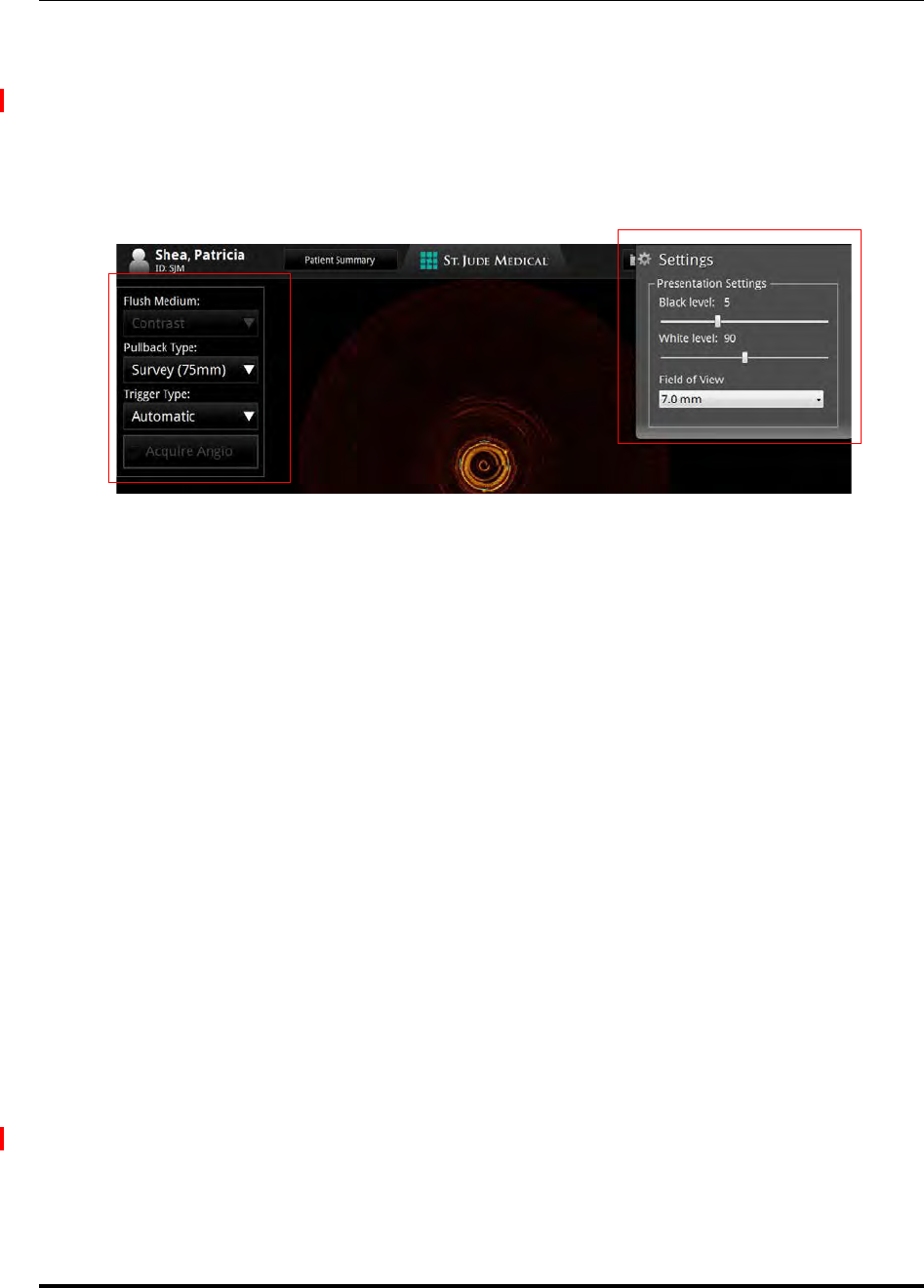
Performing an OCT Procedure
Confirm Recording Settings
St. Jude Medical
5-12 Part Number ARTUS100109403
Confirm Recording Settings
After the catheter has been connected to the DOC, confirm all settings for this recording.
1. Click the Settings button at the top of the screen.
A context-sensitive Settings menu opens on the right.
Additional pullback settings are displayed in the menu on the left. For Angio
Co-Registration, click on the Acquire Angio button. Angiography video input
must be present for the Acquire Angio button to become live.
2. Confirm all settings are correct for this recording.
NOTE: If Flush Medium has been restricted to Contrast Only, you cannot
change the Flush Medium setting. See “Setup - Acquisition/Other
Menu” on page 10-4 for more information.
If Recording Type has been set to Stationary, you cannot change the
Pullback Length setting. See “Setup - Acquisition Menu” on page
10-2 for more information.
CAUTION: To obtain accurate measurements, be sure the selection for the
Flush Medium is the same as the medium in which you are imag-
ing.
NOTE: Only 100% contrast media is approved for human OCT Imaging.
NOTE: Click the Menu button at the bottom of the screen to open the
OPTIS INTEGRATED System Setup dialog box. See Chapter 10
“User Interface Reference” for more information.
Figure 5-6: OCT Settings Menu (during Recording)

Performing an OCT Procedure
Dragonfly Imaging Catheter Insertion and Positioning
ILUMIEN OPTIS System
Instructions for Use 5-13
Dragonfly Imaging Catheter Insertion and Positioning
The guide catheter and guidewire must be inserted into the patient per normal clinical
procedures prior to insertion of the Dragonfly Imaging Catheter. The Dragonfly catheter
must be properly inserted into the guide catheter to ensure patient safety and proper oper-
ation.
Once the Dragonfly catheter has been inserted, its location, and the position of the guide
catheter, may be fine-tuned to ensure optimal imaging.
CAUTION: Ensure that no air is introduced into the system during the imaging
catheter insertion.
1. Ensure that the Dragonfly catheter is not rotating (press Standby View if necessary)
before the sterile operator begins loading and inserting. If desired, select a Vessel
and Procedure from the fields at the bottom of the screen.
2. Back-load the Dragonfly catheter's rapid-exchange lumen onto the indwelling
0.014 inch guidewire.
3. POSITION the catheter according to your catheter’s Instructions for Use.
CAUTION: Observe all advancement and movement of the Dragonfly Imag-
ing Catheter under fluoroscopy. Always advance and withdraw
the catheter slowly. Failure to observe device movement fluoro-
scopically may result in vessel injury or device damage. To
ensure proper placement, do not move the guidewire after the
Dragonfly catheter is in place.
If resistance is encountered during advancement of the Dragon-
fly Imaging Catheter, stop manipulation and evaluate under flu-
oroscopy. If the cause of resistance cannot be determined or
mitigated, carefully remove the catheter and guidewire as a unit
from the patient.
Leave the guidewire engaged with the catheter at all times dur-
ing use. Do not withdraw or advance the guidewire prior to with-
drawing the catheter.
4. Press the Live View button to start live-scan imaging (low-speed rotation of the
imaging core).
The ring around the Live View button on the DOC lights in green.
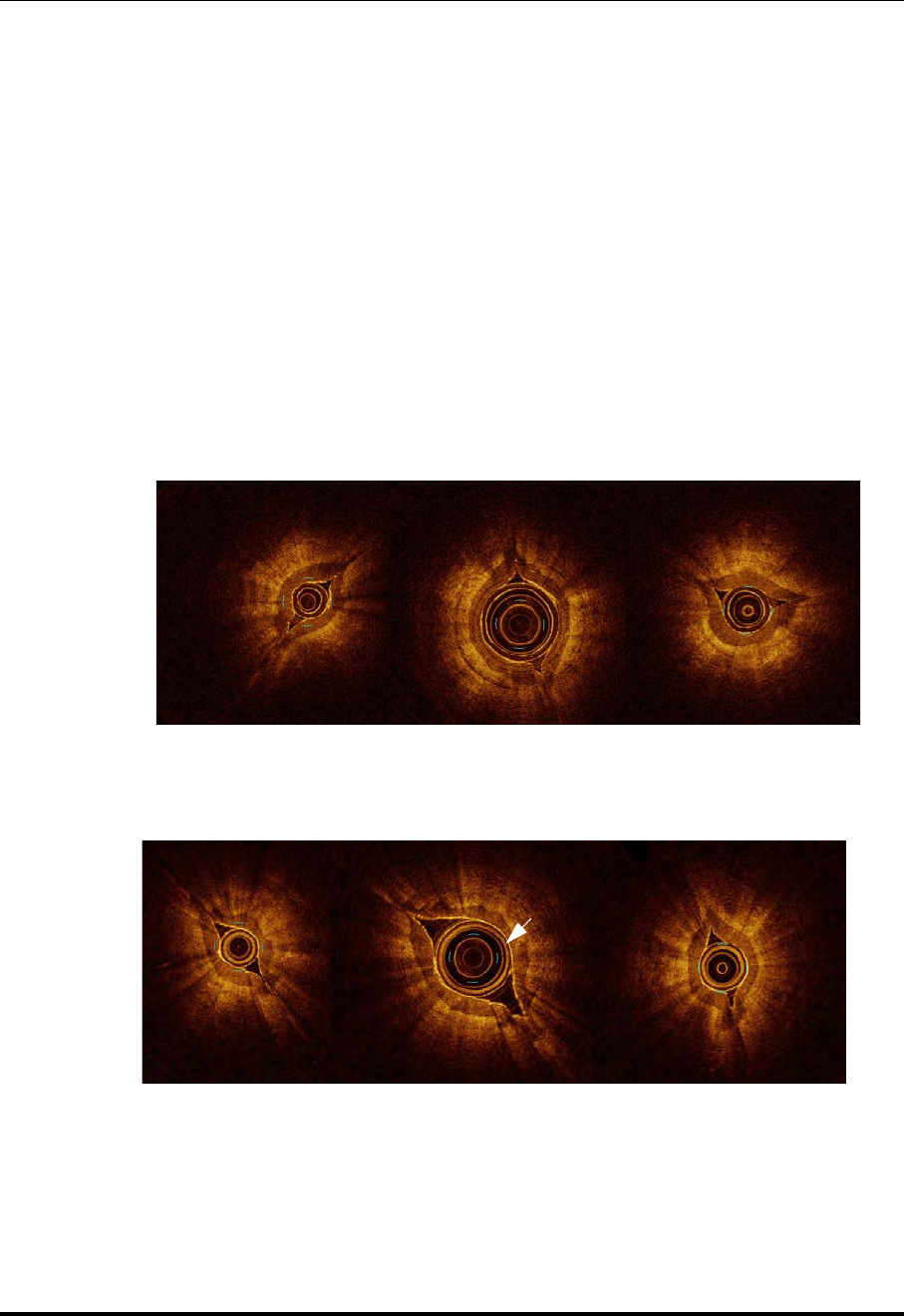
Performing an OCT Procedure
Dragonfly Imaging Catheter Insertion and Positioning
St. Jude Medical
5-14 Part Number ARTUS100109403
CAUTION: Monitor the OCT image for indications of catheter optical fail-
ure. If optical failure is suspected, return to Standby View (click
the Standby View button), remove the catheter, and replace it
with a new one.
NOTE: A pullback can not be started unless the optical fiber is fully
advanced.
5. Calibrate either by pressing the Auto Calibrate button or by using the Manual
Calibration buttons. You can also Auto Calibrate by pressing the Enable button
on the DOC.
6. Verify calibration as follows:
The image is correctly calibrated when the outermost “ring” of the catheter is cen-
tered between the 4 calibration marks.
NOTE: Ensure accurate calibration prior to a recording. Incorrect calibration
may cause early pullback initiation and incorrect measurements.
Figure 5-7: Incorrect and Correct Calibration (Dragonfly Duo shown
in fingertips)
Incorrect Incorrect Correct
Incorrect Incorrect Correct
Figure 5-8: Incorrect and Correct Calibration (Dragonfly OPTIS shown
in fingertips)
Metallic
Coating
Layer

Performing an OCT Procedure
Dragonfly Imaging Catheter Insertion and Positioning
ILUMIEN OPTIS System
Instructions for Use 5-15
You should adjust the calibration to the best approximate size
between the outer diameter of the catheter and the 4 calibration
marks.
• To calibrate automatically, press the Auto-calibrate button. In the Image
Window, the position of the catheter outer sheath is adjusted close to its final
correct position with respect to the four calibration marks.
• If necessary, click the Increase/Decrease buttons to calibrate
manually.
7. PURGE the Dragonfly Imaging Catheter by injecting ~0.1 ml contrast using the
3 ml syringe to ensure no blood has diffused into the catheter lumen.
NOTE: Application of negative pressure to draw blood into the catheter is
not recommended. Blood in the catheter lumen will obscure the
image and can be difficult to completely purge.
8. Ensure the guide catheter is oriented to preferentially direct contrast flow to the tar-
get artery, and verify angiographically that adequate flow of contrast is delivered to
the artery.
NOTE: PUFF-- Injecting a small “puff” of contrast while reviewing the
image on screen to verify that adequate flow of contrast is delivered
to the artery.
9. The operator can inject the media either by manual flush or automated injector. If
using an automated injector, verify the following for flush delivery:
• 4 ml/sec or less flush rate.
• 14 ml total flush volume.
• If using an automated injector, pressure limit 300 psi, or the nearest available
setting.
10. Verify the stopcock position on the manifold is set to allow flow from the injection
pump into the guide catheter.
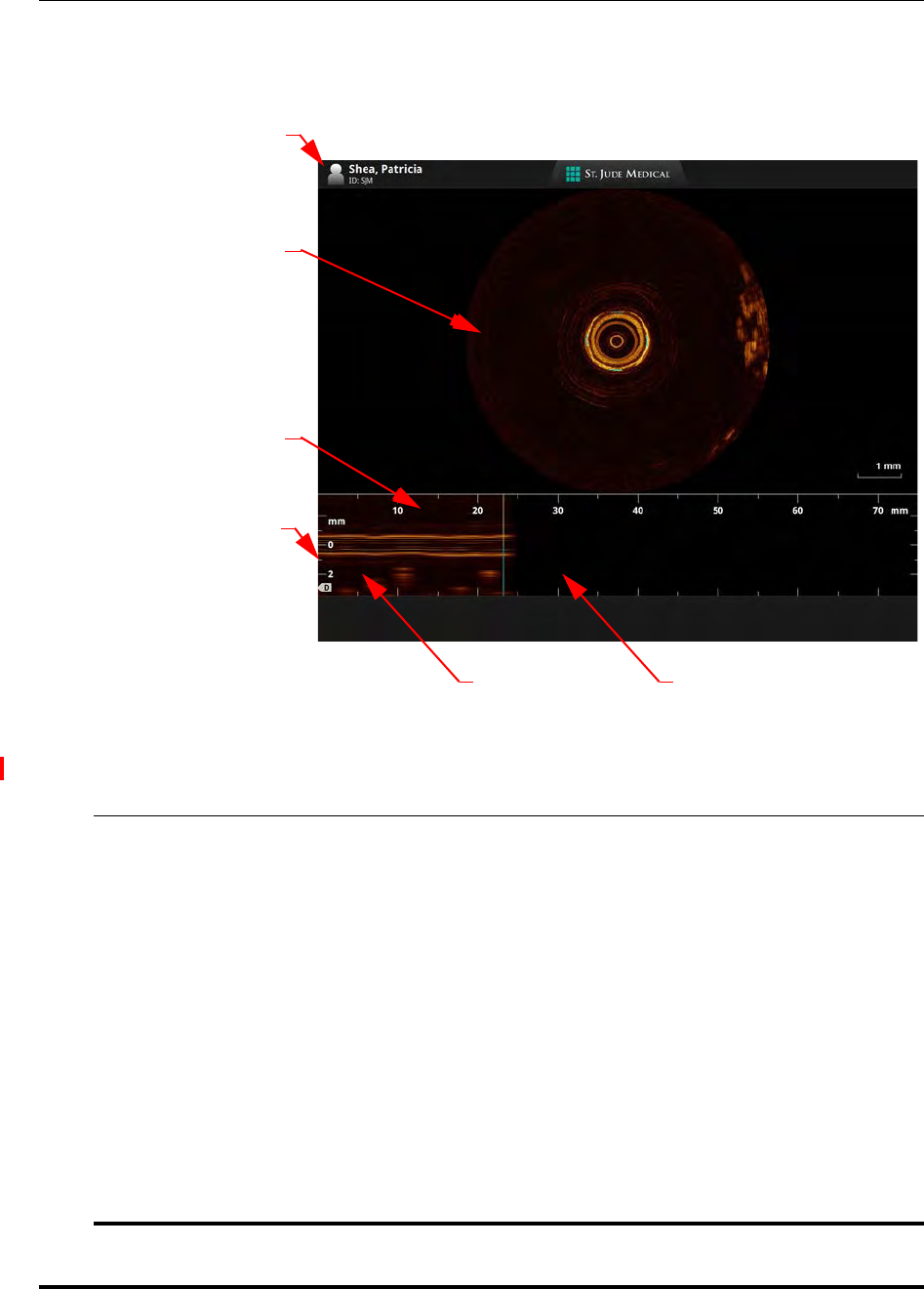
Performing an OCT Procedure
Acquiring Patient Images
St. Jude Medical
5-16 Part Number ARTUS100109403
Acquiring Patient Images
The System Display during image acquisition is shown in Figure 5-9.
Table 5-1: System Display Description - Acquisition
Patient Information Displays the Patient name and ID.
Image Window This display shows the current view by the imaging catheter lens.
Recording Calibration
Marks Recording calibration marks, measured in mm.
Note: In a Stationary recording, this is a timeline, measured in sec-
onds. See “Setup - Acquisition Menu” on page 10-2 to set the
Recording Type to Stationary.
Depth Calibration
Marks Depth of the scan in mm.
L-Mode display This displays the approximate lateral appearance of the vessel being
scanned.
Note: In a Stationary recording, the “L-Mode” is renamed “Time-
line.”
Recording (in progress) Displays the recording as it is completed.
Recording (in progress)
Recording
Calibration
Marks
L-Mode Display
Figure 5-9: System Display - Acquisition
Image Window
Depth
Patient Information
Calibration
Marks

Performing an OCT Procedure
Acquiring Patient Images
ILUMIEN OPTIS System
Instructions for Use 5-17
NOTE: If you are performing a Stationary recording, the Enable Pullback and
Start Pullback buttons are replaced with a Start Recording button. Do
not click the Start Recording button until you have notified the person
injecting the contrast media that the system is ready. Click the Start
Recording button (or Sterile Operator press the Enable button on the
DOC) after the contrast is injected. The recording begins immediately.
1. With the system in Live View, calibrate either by pressing the Auto Calibrate but-
ton or by using the Manual Calibration buttons. Click the Enable Pullback but-
ton (or Sterile Operator press the Enable button on the DOC) to allow the system to
detect initiation of the imaging flush.
You have 15 seconds to initiate the flush for the pullback.
NOTE: When acquiring the angiographic images for co-registration with
corresponding OCT recording, the imaging equipment must be sta-
tionary throughout the cineangiography. For best results, choose the
view that reduces occurrences of vessel foreshortening and branch
overlapping. This should minimize co-registration inaccuracies.
2. Notify the person injecting the contrast media that the system is enabled.
3. Begin contrast media injection (by manual flush or automated power injection).
The system automatically begins a recording once a brief sequence of clear image
frames are detected indicating the area is flushed with contrast media.
NOTE: If Trigger Type is set to Manual, click the Start Pullback button or
press the Enable button on the DOC to initiate pullback.
NOTE: If the Recording Type is set to Pullback, the recording takes
approximately 3 seconds. If set to Stationary, the recording takes
approximately 6 seconds.
NOTE: To use Angio Co-Registration with this recording, first click on the
Acquire Angio button, then step and stay on the Cine Pedal while
simultaneously capturing the entire pullback recording. Step off the
Cine Pedal upon completion of the pullback.
If the Automatically review recordings option is enabled, the image file is dis-
played for review.
Review the recording and repeat pullback procedure if needed. If the catheter is still con-
nected to the DOC, the New Recording button will be available at the bottom of the
screen.

Performing an OCT Procedure
Removing the Dragonfly Imaging Catheter
St. Jude Medical
5-18 Part Number ARTUS100109403
Removing the Dragonfly Imaging Catheter
All information obtained during imaging is automatically saved with the recording. Once
imaging is completed, the data and images may be reviewed (see Chapter 6 “Reviewing
OCT Recordings”) or transferred to removable media for review on a St. Jude Medical
Offline Review Workstation (see Chapter 8 “Exporting, Importing, and Managing
Files”).
1. Ensure that the Dragonfly catheter is not rotating (click on the Standby View but-
ton if necessary) before the sterile operator begins withdrawal and unloading.
2. When all OCT imaging is complete, withdraw the Dragonfly catheter into the guide
catheter under fluoroscopic observation.
CAUTION: If resistance is encountered during withdrawal of the Dragonfly
Imaging Catheter, stop manipulation and evaluate under fluo-
roscopy. If the cause of resistance cannot be determined or miti-
gated, carefully remove the catheter and guidewire as a unit
from the patient.
3. Remove the Dragonfly catheter from the guide catheter and guidewire.
4. Disconnect the Dragonfly catheter from the DOC by pressing the Unload button.
When the “lock” LED stops flashing, the catheter is disconnected internally. Twist
the catheter hub counter-clockwise to disengage it from the DOC.
CAUTION: Handle the Dragonfly Imaging Catheter and all other dispos-
ables used during the procedure as potential biohazards. Dis-
pose of in accordance with accepted medical practice and all
applicable laws and regulations.

Performing an OCT Procedure
Troubleshooting OCT Acquisition
ILUMIEN OPTIS System
Instructions for Use 5-19
Troubleshooting OCT Acquisition
Immediately Stopping DOC Operation
1. Press the Stop button on the DOC at any time to immediately stop operation of the
DOC. Pressing this button:
• Turns off the DOC motors, thereby stopping all optical fiber movement, both
rotational and longitudinal.
• Turns off the Imaging Engine light source.
• Stops recording and freezes the image. If Automatically review recordings
is checked in the Configure tab of the Setup dialog box, it automatically
plays back the recording once it has been saved.
• Prevents the imaging catheter lens from automatically advancing to its origi-
nal distal position.
2. The system computer remains on and the system is available for new operations.
CAUTION: If the catheter was stopped before returning to its fully advanced posi-
tion, the system displays an alert: Catheter Must Be Advanced to Con-
tinue. Click the Advance Catheter button to advance the optical fiber
within the catheter. You must advance the catheter before making
another OCT recording.
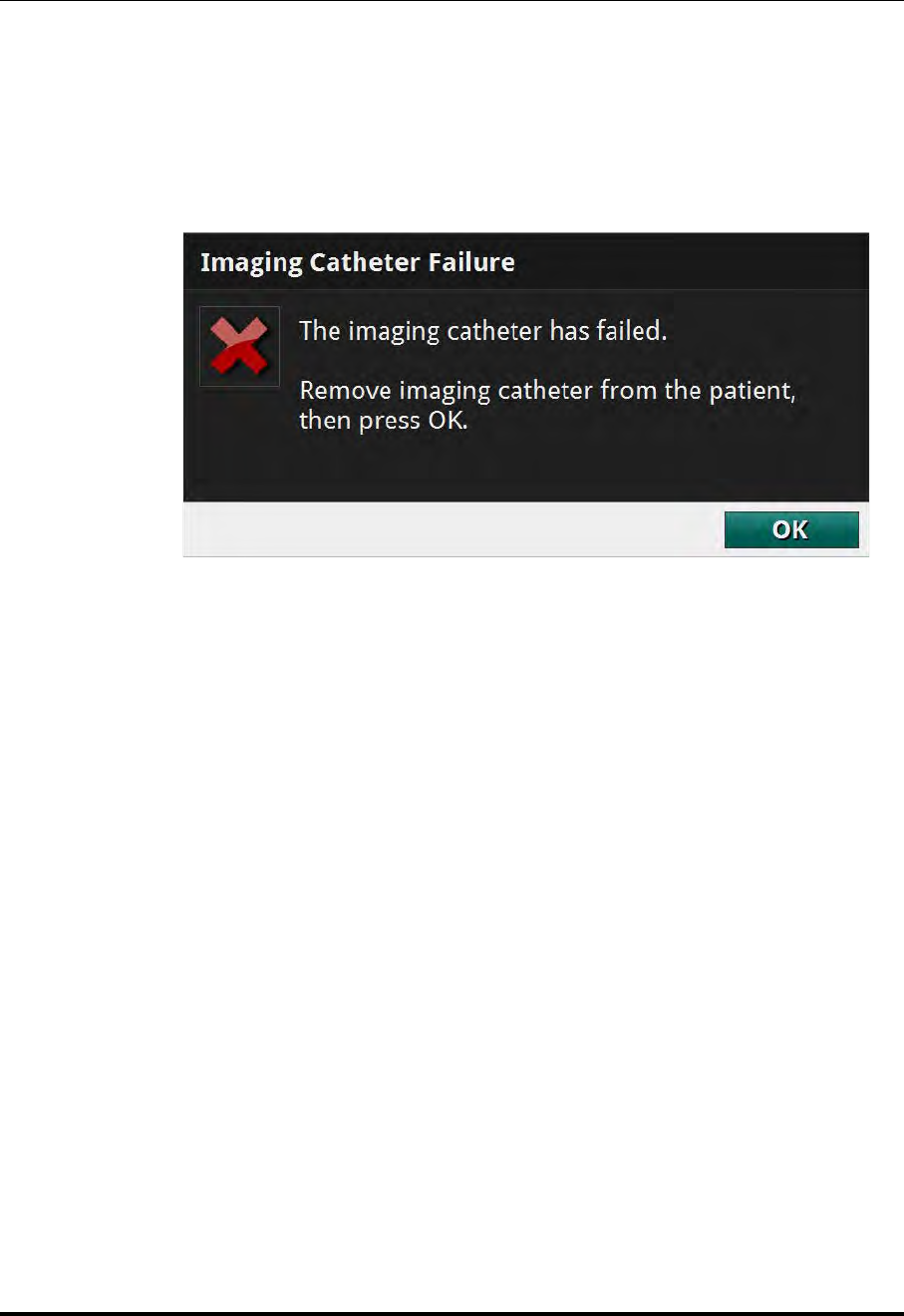
Performing an OCT Procedure
Troubleshooting OCT Acquisition
St. Jude Medical
5-20 Part Number ARTUS100109403
Catheter Failure
NOTE: These events can only occur if a catheter is connected to the DOC.
In the event of an imaging catheter failure (complete break of the optical fiber) during
either pullback or advance, the system stops automatically (and stops pullback/advance)
and displays the following message:
CAUTION: Do not click the OK button until after you have removed the
Dragonfly Imaging Catheter from the patient.
1. Withdraw the Dragonfly into the guide catheter under fluoroscopic observation.
CAUTION: If resistance is encountered during withdrawal of the Dragonfly cath-
eter, stop manipulation and evaluate under fluoroscopy. If the cause of
resistance cannot be determined or mitigated, carefully remove the
catheter and guidewire as a unit from the patient.
2. Remove the Dragonfly catheter from the guide catheter and guidewire.
3. Acknowledge the alert by clicking on OK.
Figure 5-10: Catheter Failure message
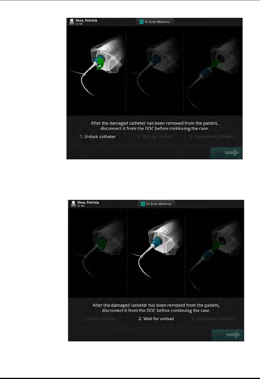
Performing an OCT Procedure
Troubleshooting OCT Acquisition
ILUMIEN OPTIS System
Instructions for Use 5-21
After acknowledging the alert, the Safe Unload Guidance displays as shown below.
4. Turn the catheter hub 1/4-turn counter-clockwise as directed. While the DOC is
unloading the catheter, the Guidance displays the screen below:
Figure 5-11: Safe Unload Guidance, Screen 1
Figure 5-12: Safe Unload Guidance, Screen 2
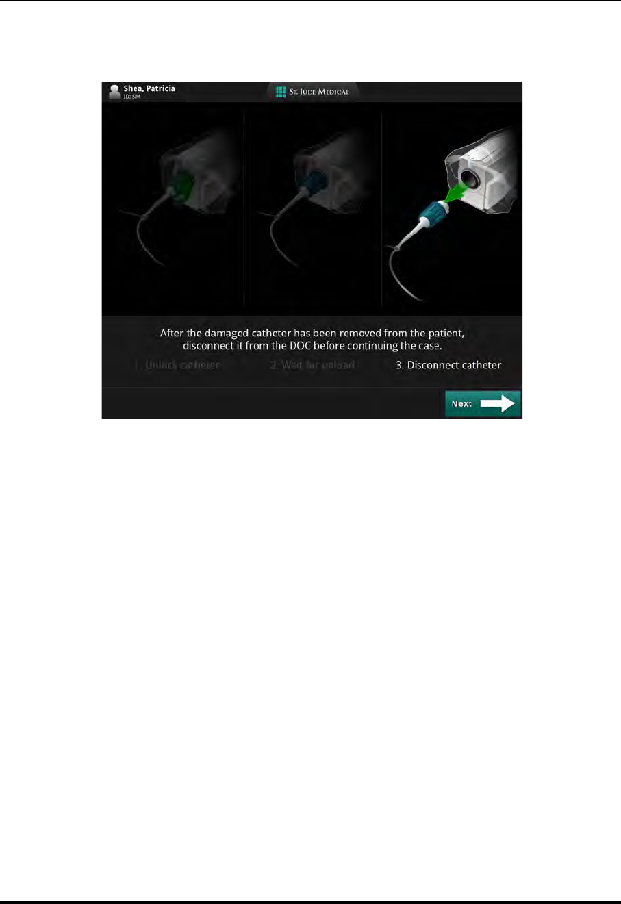
Performing an OCT Procedure
Troubleshooting OCT Acquisition
St. Jude Medical
5-22 Part Number ARTUS100109403
5. When the DOC is finished unloading the catheter, the Guidance displays the screen
below:
6. Remove the existing Dragonfly Imaging Catheter in the normal manner. Click
Next.
7. Load a new Dragonfly Imaging Catheter in the normal manner.
Figure 5-13: Safe Unload Guidance, Screen 3
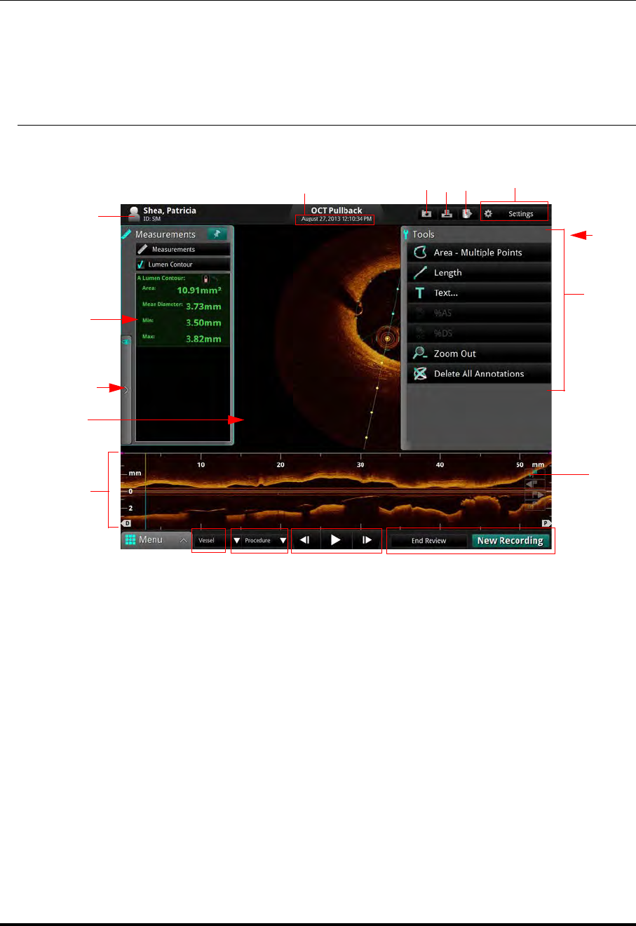
Reviewing OCT Recordings
Image Window
St. Jude Medical
6-2 Part Number ARTUS100109403
Image Window
When reviewing recordings, the Image Window shows a cross-section of the pullback or
still frame (Table 6-1).
Table 6-1: OCT Display Overview
APatient name and ID.
See “Entering New Patient Information” on page 3-6 for more information.
BRecording date and time.
CCapture button: Available on a still frame or paused recording. Click to save the current
frame.
DPrint button: Available when a USB drive is connected and the system is displaying a still
frame or paused recording. Click to print the current frame to file.
See “Printing Still Images” on page 6-13 for more information.
EExport button: Click to open the Export Wizard.
See Chapter 8 “Exporting, Importing, and Managing Files” for more information.
FSettings button: Click to open the (Playback) Settings menu.
See “Adjust Playback Settings” on page 6-9 for more information.
GFrame number: Only visible on a paused recording when Tool Panel is closed.
A
DF
G
H
J
L
P
S
BC
MNO K
Q
E
R

Reviewing OCT Recordings
Image Window
ILUMIEN OPTIS System
Instructions for Use 6-3
HTool Panel containing Measurement and Annotation tools: Use these to add measurements,
calculations, and add text to recordings and still images.
See Chapter 7 “Measurements and Annotations” for more information.
JBookmark controls: Add bookmarks to the L-Mode view.
See “Bookmark Controls” on page 6-10 for more information.
KEnd Review / New Recording : Click the End Review button to close this window and
return to the Patient Summary menu. See “Patient Summary Menu” on page 3-4 for more
information.
NOTE: While the OPTIS INTEGRATED System is connected to a Dragonfly imaging cathe-
ter, the button New Recording appears here. Click the New Recording button to
close this review and begin a new OCT recording.
LPlayback controls: Control the playback of the OCT recording. Not available with still
images.
See “Playback Controls” on page 6-6 for more information.
MProcedure list: Click to open a drop-down list of procedures to describe this recording.
NVessel list: Click to open a drop-down list of vessels to describe this recording.
OMenu: Displays the context-sensitive menu. Click to access the Setup and playback Cali-
bration controls. See Chapter 10 “User Interface Reference” for more information on the
Setup Menu; see “Calibration Adjustment” on page 6-7 for more information on the Cali-
bration Menu.
PL-Mode view: An approximate lateral representation of the vessel for this recording. Not
available with still images.
See “L-Mode View” on page 6-4 for more information.
QImage Window: A cross-section view of the vessel.
RView Panel: Control display features including L-Mode and optional features such as 3D
and Lumen Profile.
SMeasurements Panel: This section lists measurements from the current image; click on a
measurement to highlight it in the Image Window.
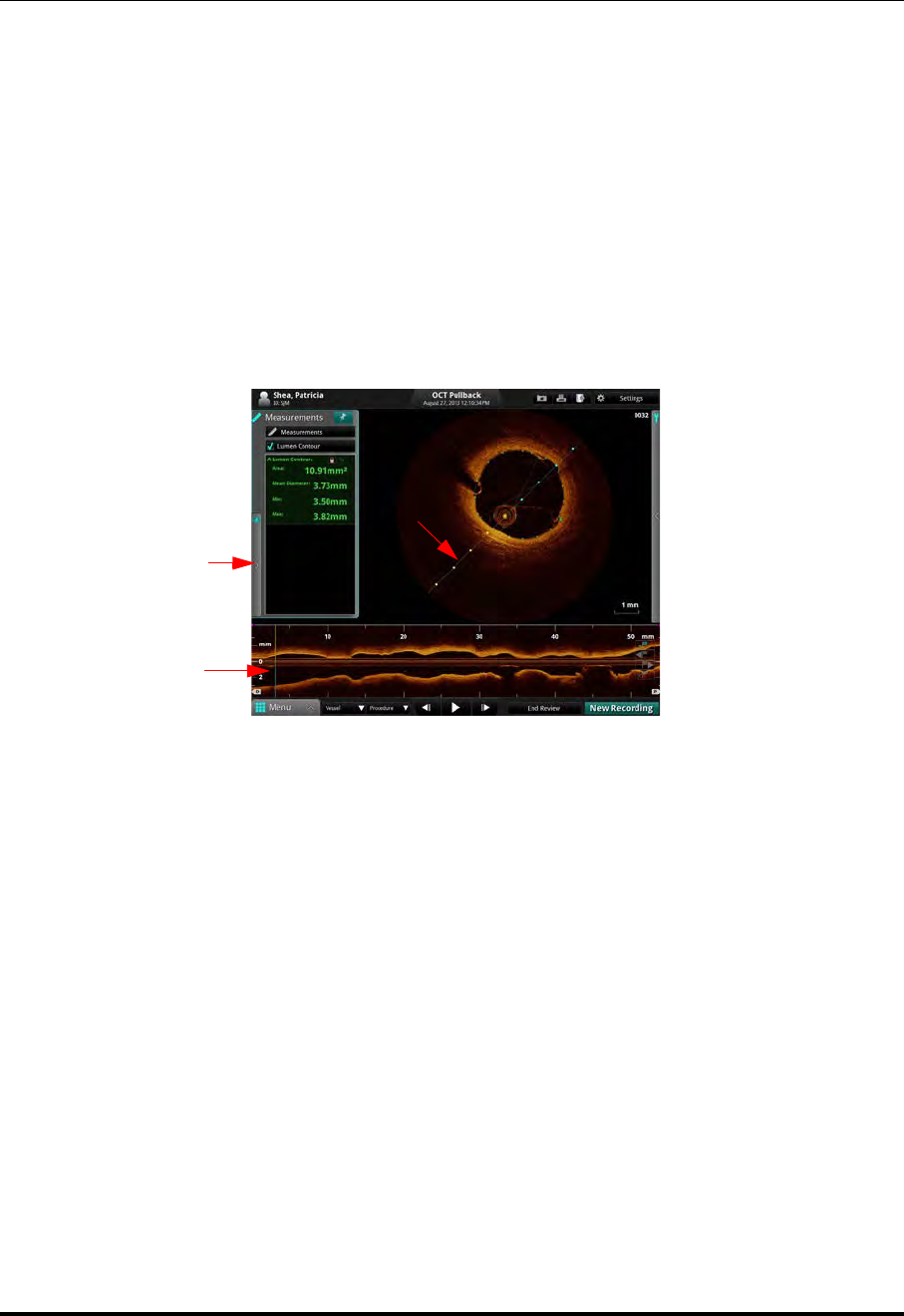
Reviewing OCT Recordings
L-Mode View
St. Jude Medical
6-4 Part Number ARTUS100109403
L-Mode View
NOTE: If reviewing a Stationary recording, the L-Mode display is renamed Time-
line. The Timeline represents the stationary view of the catheter during the
six seconds of recording.
During the OCT pullback recording, the system captures evenly spaced cross-section
images and uses them to construct a lateral view of the vessel anatomy. The lateral view
is shown in the L-Mode display in the lower portion of the screen; the distal portion of the
recording is to the left.
NOTE: The width of the L-Mode window represents the entire range of the record-
ing.
Table 6-2: L-Mode view
ACut-Plane Indicator.
BL-Mode display.
CCurrent Frame Indicator. Click and drag this to change the lateral view shown in the
L-Mode display.
B
A
L-Mode
View Tab
C

Reviewing OCT Recordings
L-Mode View
ILUMIEN OPTIS System
Instructions for Use 6-5
Limitations of L-Mode Data
Please be aware of the following limitations of L-Mode data:
• Due to the catheter’s arbitrary position within the vessel, L-Mode data may not be
representative of the actual vessel lumen.
• The vessel diameter shown in the L-Mode reconstruction may appear significantly
smaller than the actual diameter when the catheter position is off center and close to
the vessel wall. To avoid misinterpreting the image when this occurs, rotate the cut-
plane to examine all views of the L-Mode.
• Although a vessel may curve, the L-Mode view always appears straight because of
the limitations of reconstruction.
• Artifacts caused by the relative motion of the catheter and the vessel often result in
a saw-toothed appearance of the reconstruction and can lead to misinterpretation by
inexperienced users.
• Shortening or lengthening artifacts in the L-Mode reconstruction may occur due to
the relative motion of the Dragonfly catheter with respect to the coronary artery
caused by the patient’s heart motion.

Reviewing OCT Recordings
Playback Controls
St. Jude Medical
6-6 Part Number ARTUS100109403
Playback Controls
Table 6-3: Playback Controls
AMenu: Displays the context-sensitive menu. Click to access the Setup and playback
Calibration controls. Only available with a still image or paused recording.
BVessel list: Click to open a drop-down list of vessels to describe this recording.
CProcedure list: Click to open a drop-down list of procedures to describe this recording.
DStep Backward : Click to move the recording back one frame at a time. Click and hold
this button to move back rapidly. Not available with still images.
EPlay/Pause : Plays or Pauses the recording. If you pause a recording, the frame number
is displayed in the upper right corner of the image area. Not available with still images.
FStep Forward : Click to move the recording forward one frame at a time. Click and
hold this button to move forward rapidly. Not available with still images.
GEnd Review / New Recording : Click the End Review button to close this window
and return to the Patient Summary menu.
NOTE: While the system is connected to a Dragonfly Imaging Catheter, the button
New Recording appears here. Click the New Recording button to close
this review and begin a new OCT recording.
A E F G
B C D
XX
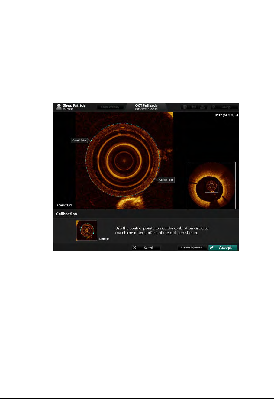
Reviewing OCT Recordings
Calibration Adjustment
ILUMIEN OPTIS System
Instructions for Use 6-7
Calibration Adjustment
Use the Adjust Calibration tool to adjust the calibration of the recording.
1. Use the Playback Controls at the bottom of the screen to pause the playback.
2. Hover or click on the Menu button at the bottom of the screen and select the Cali-
bration option.
The Calibration tool opens. The image is zoomed and the calibration circle with
two control points is sized approximate to the outside diameter of the catheter.
3. Click and drag on the control points until the calibration circle traces the outside
diameter of the catheter as shown in the sample picture at the bottom of the screen.
NOTE: Adjustments made here are for size, not alignment. The catheter may
not appear centered in all frames during playback. This is normal.
4. Click the Accept button save the calibration, or click Cancel to close the calibration
tool without saving the adjustment.
Figure 6-1: Playback Calibration (DragonFly Duo shown, in progress)

Reviewing OCT Recordings
Calibration Adjustment
St. Jude Medical
6-8 Part Number ARTUS100109403
NOTE: If necessary, you can return the recording to its default calibration by
clicking the Remove Adjustment button.
If you remove or change the calibration, any changes that you have
made to the automatically-generated Lumen Profile contours are
reset. See “Lumen Profile Display Option” on page 7-20 for more
information.
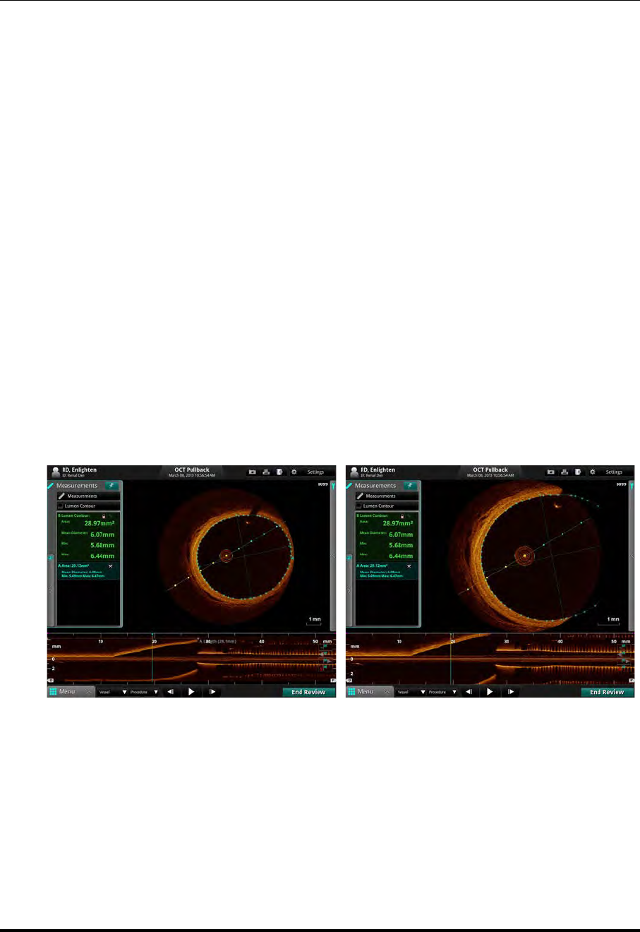
Reviewing OCT Recordings
Adjust Playback Settings
ILUMIEN OPTIS System
Instructions for Use 6-9
Adjust Playback Settings
1. Click the Settings button at the top of the screen.
A context-sensitive menu opens.
2. Click and drag the Playback Speed slider bar to set the playback speed.
3. Click and drag the Rotation slider bar to rotate the image shown in the cross-sec-
tion view.
NOTE: When an image is rotated, the L-Mode cut-plane marker (if visible)
and any displayed measurements and annotations are also rotated.
4. Click and drag the Black level and White level slider bars to set the black and white
balance in the image.
5. Click the arrow on the Field of View drop-down menu to display the list of diame-
ter sizes.The default setting is 7.0 mm.
The Field of View setting controls the size of the image displayed on screen. A
smaller Field of View setting equals a larger magnification. Click a size to select it.
NOTE: Clicking on the image will also change the zoom level. See “Quick Zoom”
on page 7-16.
Figure 6-2: Field of View Settings
Field of View 10.0 mm Field of View 5.0 mm
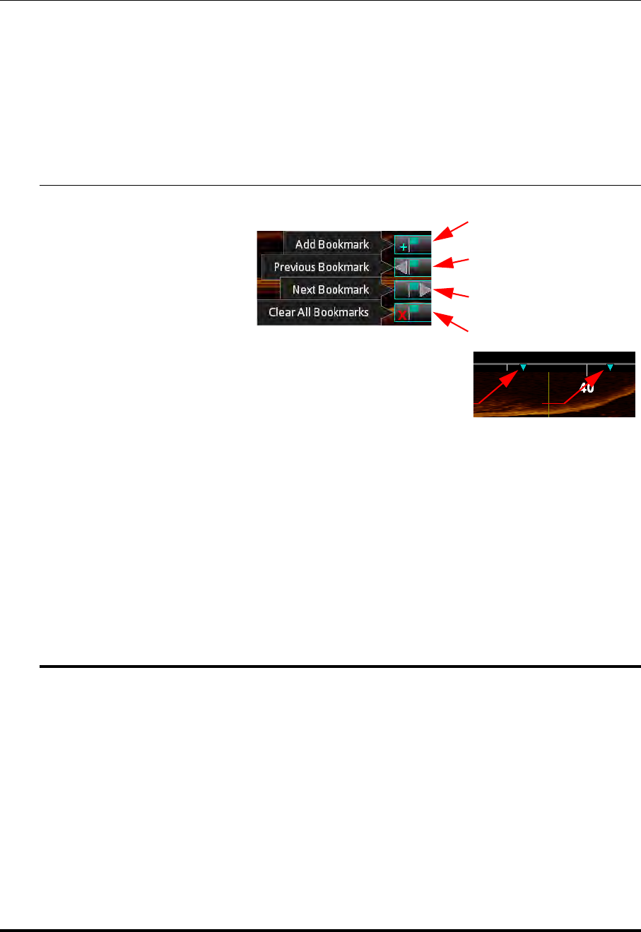
Reviewing OCT Recordings
Bookmark Controls
St. Jude Medical
6-10 Part Number ARTUS100109403
Bookmark Controls
The System allows you to add bookmarks to mark frames for further review.
NOTE: Bookmark controls are only available when an L-Mode view is displayed
in a recording.
Table 6-4: Bookmark Controls
AAdd/Remove Bookmark : Applies or removes a bookmark
from the current frame. After a bookmark has been applied
to a frame, the position of the bookmark is indicated in the
L-Mode view with a green triangle.
Click on a bookmark indicator to jump to the bookmarked frame.
NOTE: Frames with measurements and annotations are bookmarked automatically.
See Chapter 7 “Measurements and Annotations” for more information.
BPrevious Bookmark : Seeks backward to the previous bookmarked frame. If there are
no previous bookmarks, it continues seeking from the end of the recording. Unavailable
if there are no bookmarks.
CNext Bookmark : Seeks forward to the next bookmarked frame. If there are no subse-
quent bookmarks, it continues seeking from the beginning of the recording. Unavailable
if there are no bookmarks.
DClear All Bookmarks : Clears all bookmarks from the current recording. Unavailable
if there are no bookmarks.
A
B
C
D
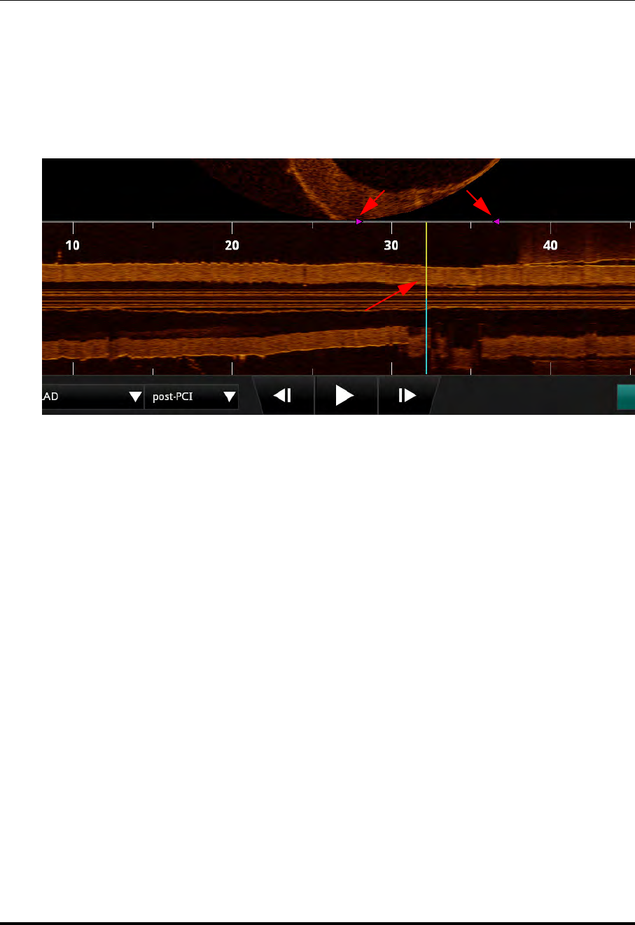
Reviewing OCT Recordings
Setting Playback Range
ILUMIEN OPTIS System
Instructions for Use 6-11
Setting Playback Range
By default, the system plays the entire length of a pullback during the review. You can
shorten the length of the playback by moving the ends of the playback range.
NOTE: Playback range markers are only available on recordings in the L-Mode
view. By default, they are at the distal and proximal ends of the recording.
To change the playback range:
1. Use the Playback Controls at the bottom of the screen to pause the playback.
2. Click on the range markers (purple triangles) and position them before and after the
area to be played during review.
NOTE: If the recording is exported as an AVI file, this range determines the length
of the exported recording.
NOTE: If the L-Mode view is changed (for example, turned Off), the playback
range is restored to the full length of the recording.
Playback Range markers
Current Frame Indicator
Figure 6-3: Adjusted Playback Range

Reviewing OCT Recordings
Exporting a Recording or Still Frame
St. Jude Medical
6-12 Part Number ARTUS100109403
Exporting a Recording or Still Frame
Refer to Chapter 8 “Exporting, Importing, and Managing Files” for more informa-
tion on exporting a recording or still frame.
Capturing Still Images
You can use the Capture button to save a still image from a recording, or to save
a copy of an existing still frame. All measurements and annotations on that screen
are saved with the captured image.
NOTE: The Capture button is unavailable while a recording is playing. Pause the
playback at the frame that you want to capture.
Saving a Still Image
1. Display the frame that you want to capture.
2. Click the Capture button.
A confirmation message appears, and the captured image appears in the Patient
Summary menu.
NOTE: The still image is saved with the same date as the source file. It is
grouped in the Patient Summary menu with other recordings and
images of the same date.
In the Patient Summary menu, the system adds the frame number to the title of the
captured image (for example, “OCT Frame 145”).

Reviewing OCT Recordings
Printing Still Images
ILUMIEN OPTIS System
Instructions for Use 6-13
Printing Still Images
You can use the Print button to print the current screen (including still frame,
L-Mode, and any visible annotations) to an attached USB drive. All measurements
and annotations on that screen are saved with the captured image.
NOTE: The Print button is unavailable while a recording is playing. Pause the
playback at the frame that you want to print.
NOTE: If you are printing the file to a USB drive, you can set the file format. See
“Setup - Print Menu” on page 10-25 for more information.
Printing a Still Image
1. Display the frame that you want to print.
2. Click the Print button.
A confirmation message appears, and the file is saved on the attached USB drive.
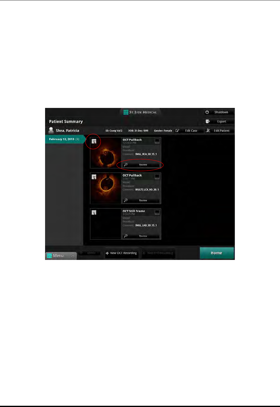
Reviewing OCT Recordings
Reviewing with Angio-Coregistration
St. Jude Medical
6-14 Part Number ARTUS100109403
Reviewing with Angio-Coregistration
Only pullback images that contain angio-coregistration data can be used for this type of
review. Identify the presence of angio-coregistration data by locating a black and white
angiographic thumbnail image in the upper-left corner of the pullback on the Patient
Summary screen.
1. From the Patient Summary screen, identify a pullback that contains a black and
white angiographic thumbnail image in the upper-left corner.
2. Click the review button. The OCT review begins to playback.
Figure 6-4: Angio-Coregistration Thumbnail Image
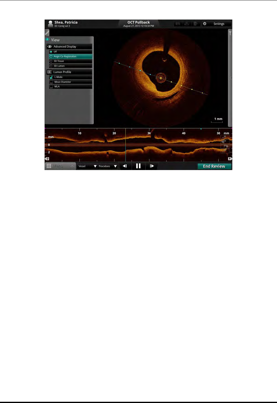
Reviewing OCT Recordings
Reviewing with Angio-Coregistration
ILUMIEN OPTIS System
Instructions for Use 6-15
3. Pause the recording and click the Angio Co-Registration button under the View
menu to initiate the Angio Co-Registration process. The angiography displays in
the left window.
NOTE: To view the angiography along with the MLA data, click the MLA
box in the View menu. Mean Diameter or Area is automatically
selected when MLA is clicked.
Figure 6-5: View Menu, Angio Co-Registration Button
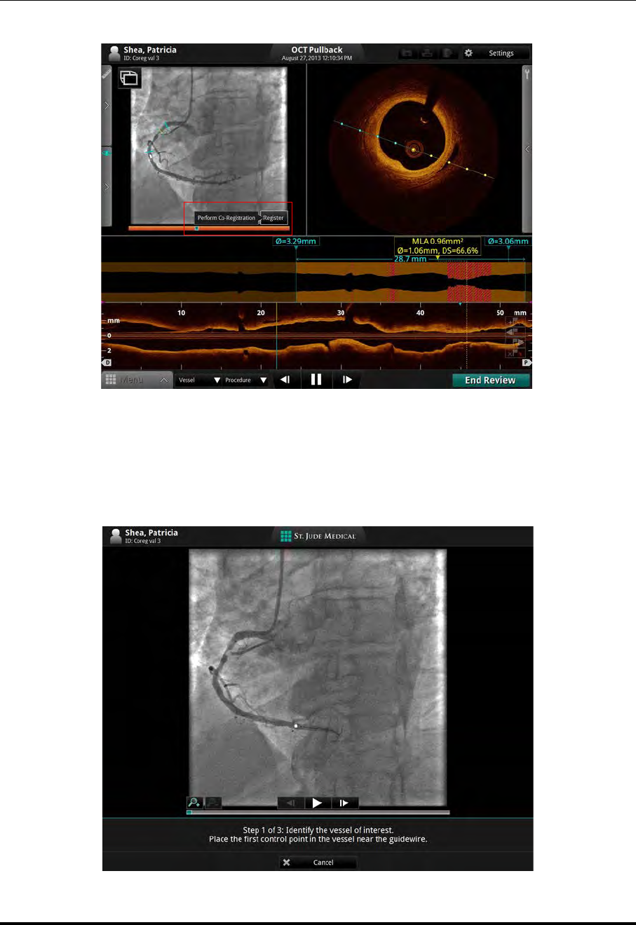
Reviewing OCT Recordings
Reviewing with Angio-Coregistration
St. Jude Medical
6-16 Part Number ARTUS100109403
4. Click on the Register button to initiate the co-registration. Step 1 of the Angio
Co-Registration Guidance displays.
Figure 6-6: Angio Co-Registration: Register
Figure 6-7: Angio Co-Registration Guidance, Step 1
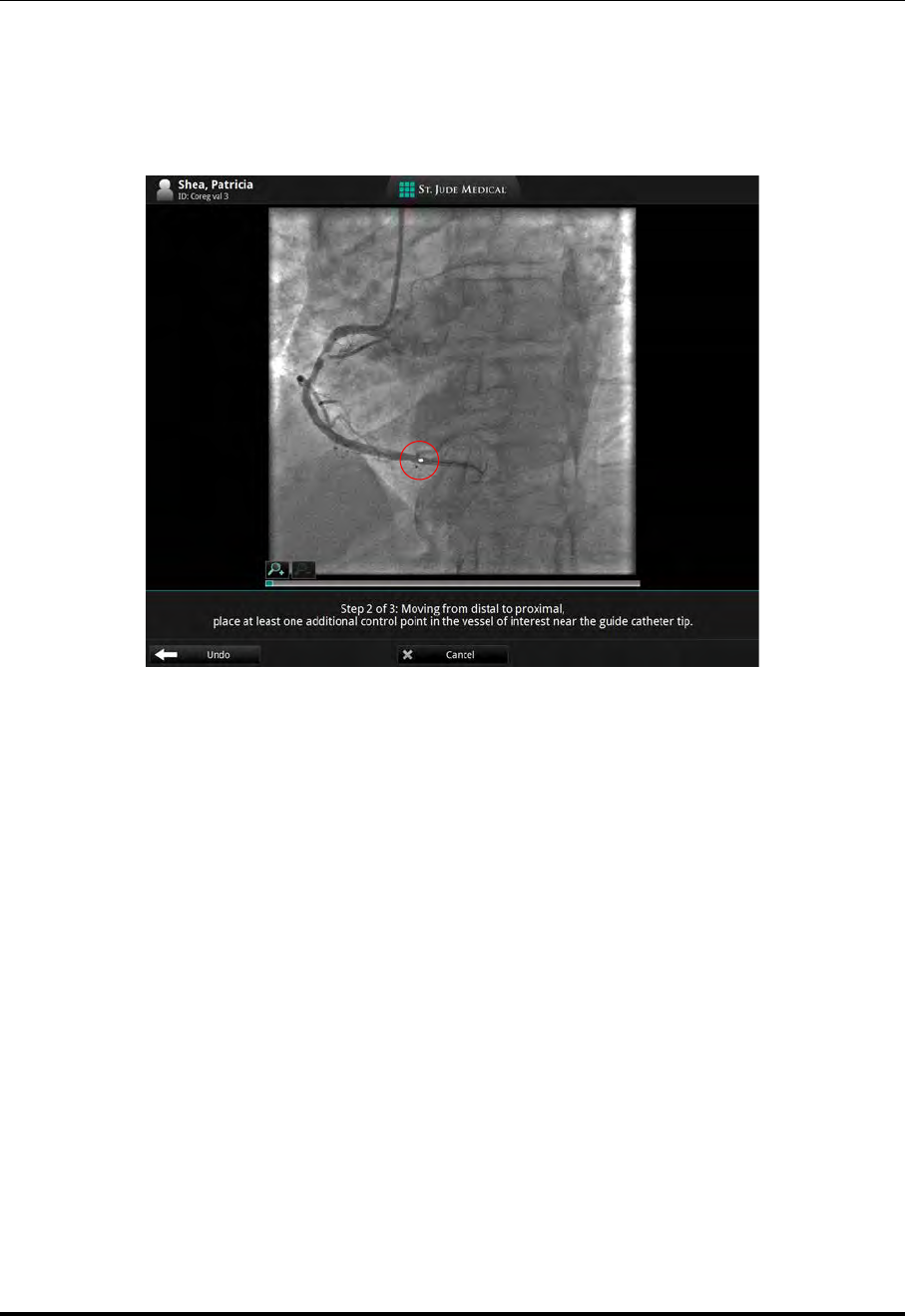
Reviewing OCT Recordings
Reviewing with Angio-Coregistration
ILUMIEN OPTIS System
Instructions for Use 6-17
5. Set the first (distal) control point by placing the cursor in the vessel of interest, on
the guidewire (or just proximal of the guidewire), and clicking. A white control
point and Step 2 of the Angio Co-Registration Guidance displays.
6. Moving distal to proximal, set at least one additional control point by placing the
cursor in the vessel of interest, distally near the guide catheter tip and clicking.
Additional white control point(s) display. The system draws a line which traces the
vessel of interest and connects the control points. The Continue button displays.
Figure 6-8: Angio Co-Registration Guidance, Step 2
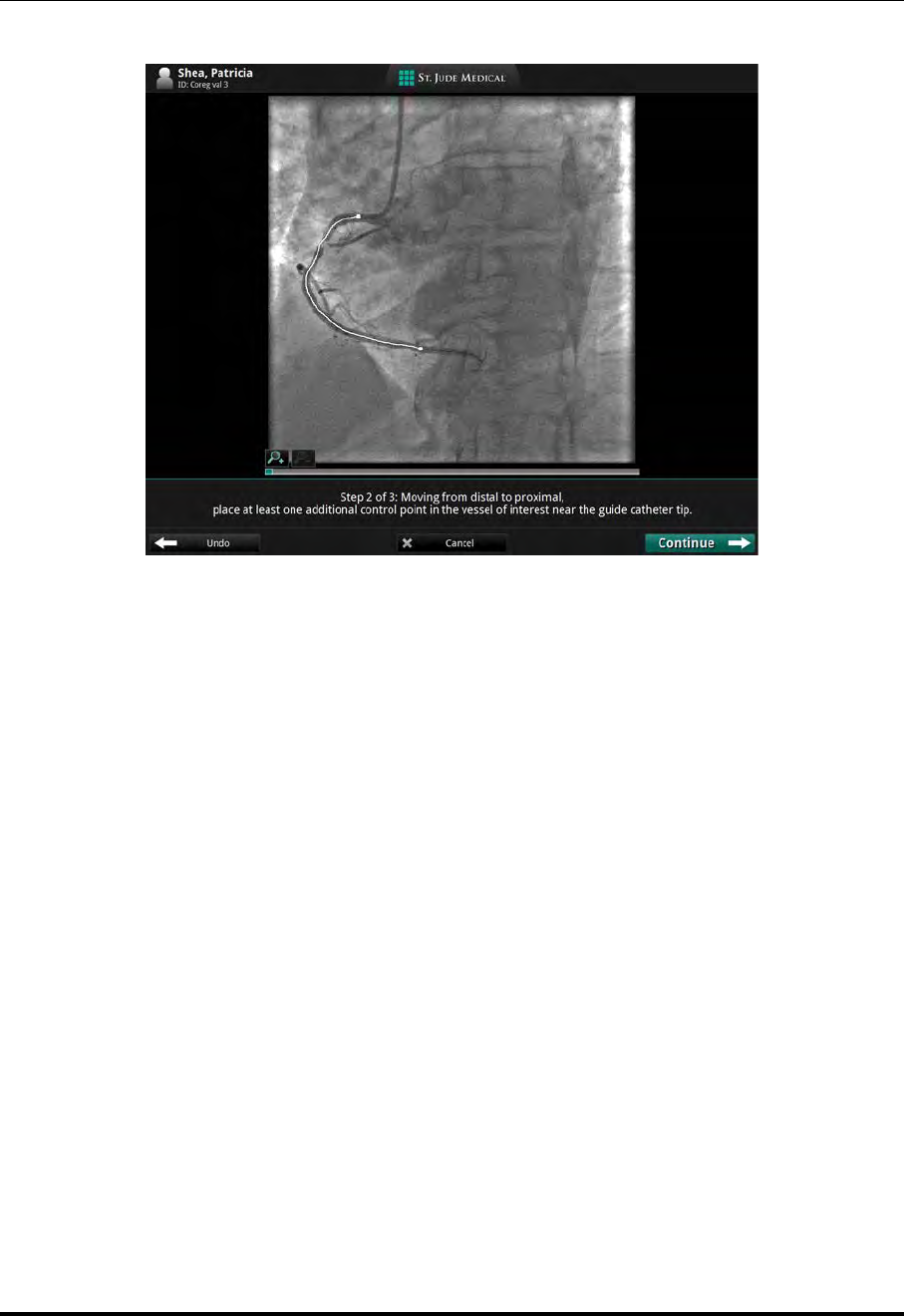
Reviewing OCT Recordings
Reviewing with Angio-Coregistration
St. Jude Medical
6-18 Part Number ARTUS100109403
NOTE: If after placing the proximal point, an incorrect vessel path is traced,
click the Undo button, then replace the proximal control point. Fol-
low the on-screen guidance.
7. Verify that the trace is in the vessel of interest. Click the Continue button. Angio
Co-Registration Guidance, Step 3 displays.
Figure 6-9: Angio Co-Registration Guidance, Step 2 with Trace
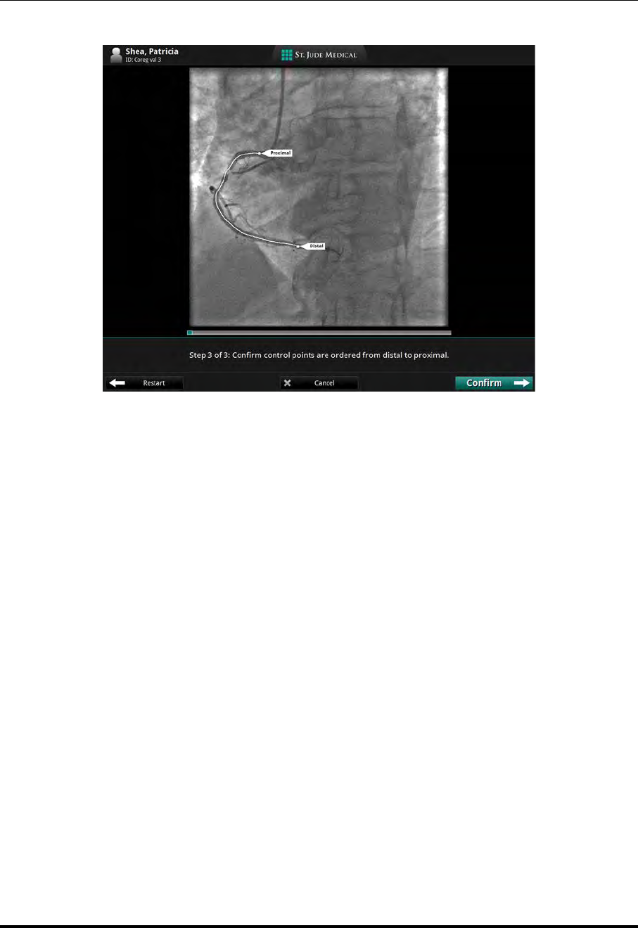
Reviewing OCT Recordings
Reviewing with Angio-Coregistration
ILUMIEN OPTIS System
Instructions for Use 6-19
8. Click the Confirm button to accept the path within the vessel of interest. The
Please wait for co-registration screen displays while the system correlates the
angiography with the OCT frames. When the co-registration is complete, the
Coregistration completed successfully screen displays.
NOTE: If either the selected proximal or distal points do not allow the sys-
tem to generate a full Angio Co-Registration, a Warning screen dis-
plays. Click Cancel. Following the on-screen guidance, replace both
distal and proximal control points along the vessel of interest, then
click the Confirm button.
Figure 6-10: Angio Co-Registration Guidance, Step 3
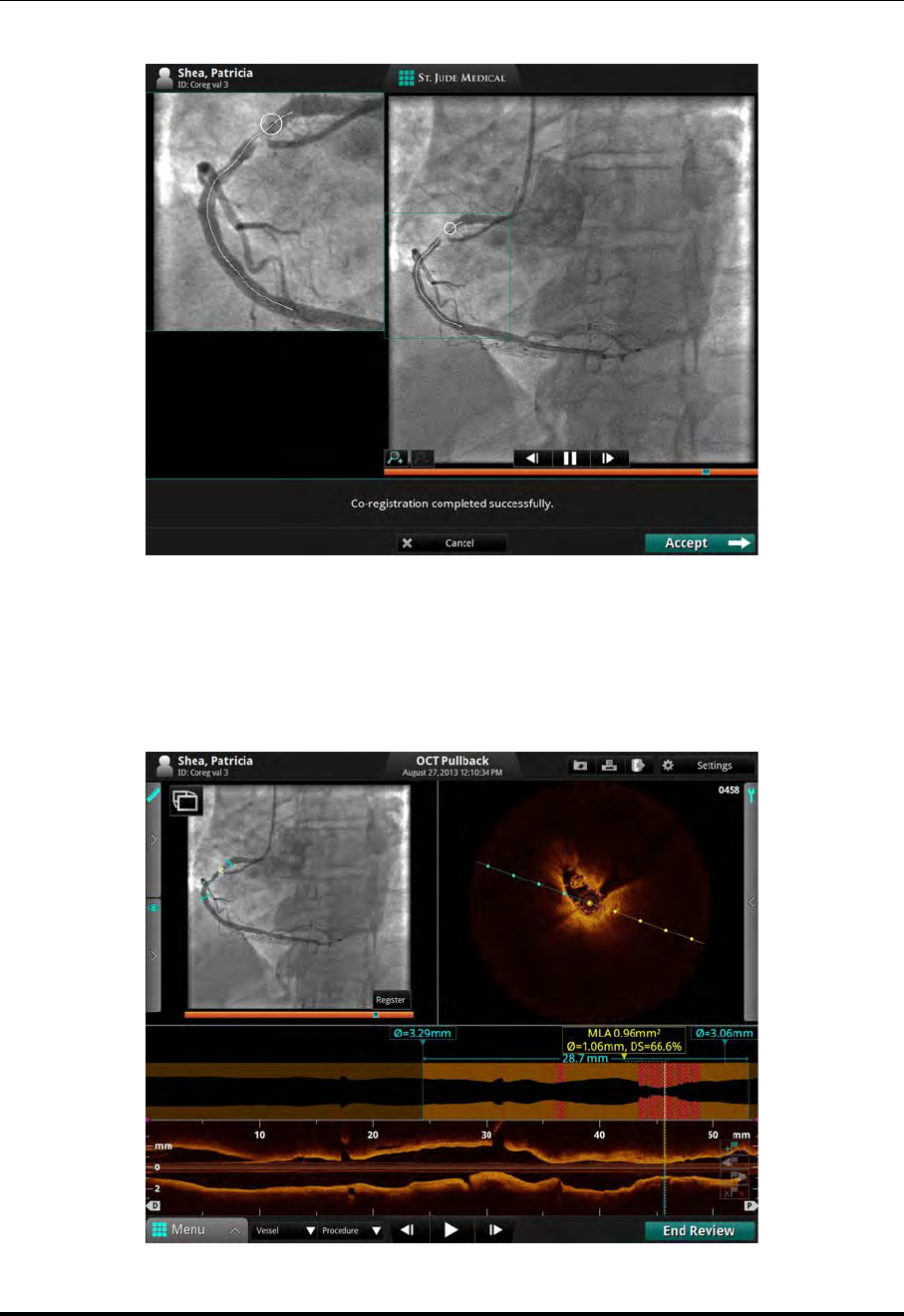
Reviewing OCT Recordings
Reviewing with Angio-Coregistration
St. Jude Medical
6-20 Part Number ARTUS100109403
9. Click the Accept button to use the successful Angio Co-Registration. The main
screen displays the co-registered images.
Figure 6-11: Angio Co-registration completed successfully screen
Figure 6-12: Main Screen showing Angio Co-Registration

Reviewing OCT Recordings
Reviewing with Angio-Coregistration
St. Jude Medical
6-22 Part Number ARTUS100109403

ILUMIEN OPTIS System
Instructions for Use 7-1
Measurements and Annotations 7
Measurements and Text Callouts in the Image Files
Measurements and text callouts that are added to images do not change the underlying
image data. The unannotated image is always preserved and can be reviewed without the
measurements and callouts. All measurements and annotations added during the proce-
dure are preserved in the file.
Measurements and text callouts can be modified or deleted, and pen color, line width and
point size can be set. In addition, pen color can be set to automatically cycle so that sub-
sequent measurements are displayed in different colors. For information on setting pen
color, line width, and point size, see “Setup - Measurements/Labels Menu” on page
10-24.
CAUTION: If you want to make measurements on files which will be exported to
standard formats, you must make the measurements BEFORE
exporting the images. Using non-OCT software to measure standard
format images will not produce accurate measurements.
CAUTION: Do not use images that have been exported to JPEG or Compressed
AVI formats for clinical decision making. These formats use compres-
sion methods that may degrade the image quality.
NOTE: All measurements and calculations can be made in the cross-section view
of the OCT image, but only horizontal length measurements and text anno-
tations can be made in the L-Mode view.
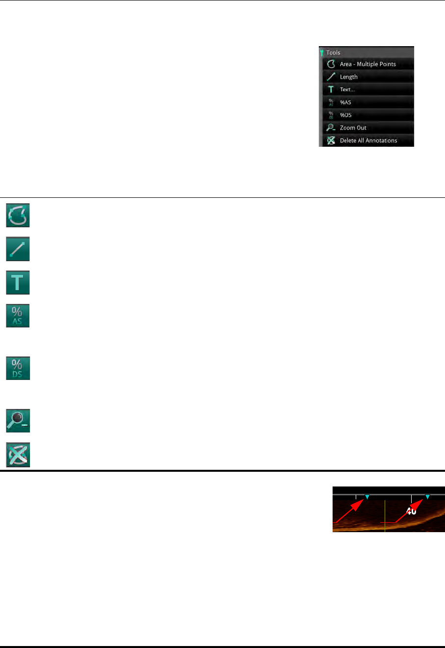
Measurements and Annotations
Measurement and Annotation Tools
St. Jude Medical
7-2 Part Number ARTUS100109403
Measurement and Annotation Tools
When the OCT playback is paused, or displaying a still
image, the measurement and annotation tools can be
accessed on screen by hovering over the Tools Panel
(wrench symbol). As measurements are added to the
image, they are labeled with successive control letters
(A, B, C, etc., up to 26 measurements per frame).
NOTE: Tools appear black when they are
unavailable.
NOTE: After a measurement or text annotation has been
applied to a frame, the position of the bookmark
is indicated in the L-Mode view with a green tri-
angle.
Click on a bookmark to jump to it.
Table 7-1: Measurement and Annotation Tool Functions
Area - Multiple Points : Manually place points to trace and measure an area on a frame. This
also generates the min., max., and mean diameter measurements for the given area.
Length : Make a distance measurement on a frame.
Text... : Opens the Enter Note menu to enter text at the cursor position.
%AS (Percent Area Stenosis) : Calculates the relative size of two areas drawn in the current
frame.
NOTE: If there are fewer than two areas on the current frame, this button is not available.
%DS (Percent Diameter Stenosis) : Calculates the relative size of two lengths (or diameters)
drawn in the current frame.
NOTE: If there are fewer than two lengths on the current frame, this button is not available.
Zoom - / Zoom + : Switches between zoom levels. See “Adjust Playback Settings” on page
6-9 for more information.
Delete All Annotations : Click to delete all annotations and measurements.
Figure 7-1: Tools

Measurements and Annotations
Verifying Calibration
ILUMIEN OPTIS System
Instructions for Use 7-3
Verifying Calibration
Before making measurements, you must verify the calibration. If the calibration for this
recording or still image has not been adjusted, or if it has been reset, the calibration tool
appears when you begin to take a measurement. See “Calibration Adjustment” on page
6-7 for more information.
Once the calibration is accepted, you can begin taking measurements.
NOTE: Calibration before making measurements should not be necessary when
using the Dragonfly OPTIS catheter. The OPTIS Integrated software in
conjunction with the Dragonfly OPTIS catheter uses Continuous Calibra-
tion technology to eliminate the need for this step in the workflow.
Techniques to Improve Measurement Accuracy
Follow these guidelines to improve measurement accuracy:
• Before making measurements, use the Zoom function to zoom into the region of
interest until you can clearly see borders and other features you want to measure
(see “Field of View” on page 7-14).
• Place the measurement cursor correctly on the image, using the same measurement
technique each time you perform the same type of measurement.
• Avoid making measurements in areas that have artifacts that disguise tissue.
Measurements and Annotations in the L-Mode View
All annotations and measurements are typically made in the cross-section view area of the
Image Window. Only horizontal measurements, useful for determining pullback distance,
are permitted in the L-Mode view.
CAUTION: Artifacts may result in misrepresentation of L-Mode data, so L-Mode
is not recommended for quantization of clinical information.
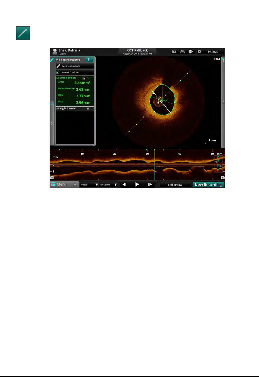
Measurements and Annotations
Length Measurements
St. Jude Medical
7-4 Part Number ARTUS100109403
Length Measurements
The system calculates and displays length as the distance in millimeters (mm)
between 2 points placed on an image in either the cross-section or L-Mode views.
Figure 7-2: Length Measurement

Measurements and Annotations
Length Measurements
ILUMIEN OPTIS System
Instructions for Use 7-5
Making a Length (Distance) Measurement
1. Select the still image or paused recording that you want to measure.
2. Click on the Length button (Figure 7-2). The cursor changes to a pen.
3. Click anywhere in the Image Window (cross-section view or L-Mode view) to
place the starting point for the length measurement.
NOTE: Both start and end points must be in the same view. For
example, if the starting point is placed in the cross-section
view, the end point must also be in the cross-section view.
To cancel the measurement, press the <Esc> key or click
the Cancel button.
4. Use the mouse to position the pen cursor at the end point and click to set the point.
The completed, labeled distance measurement result appears in the Annotations
Panel. If you position the cursor over the line, the length is shown over the center of
the line.
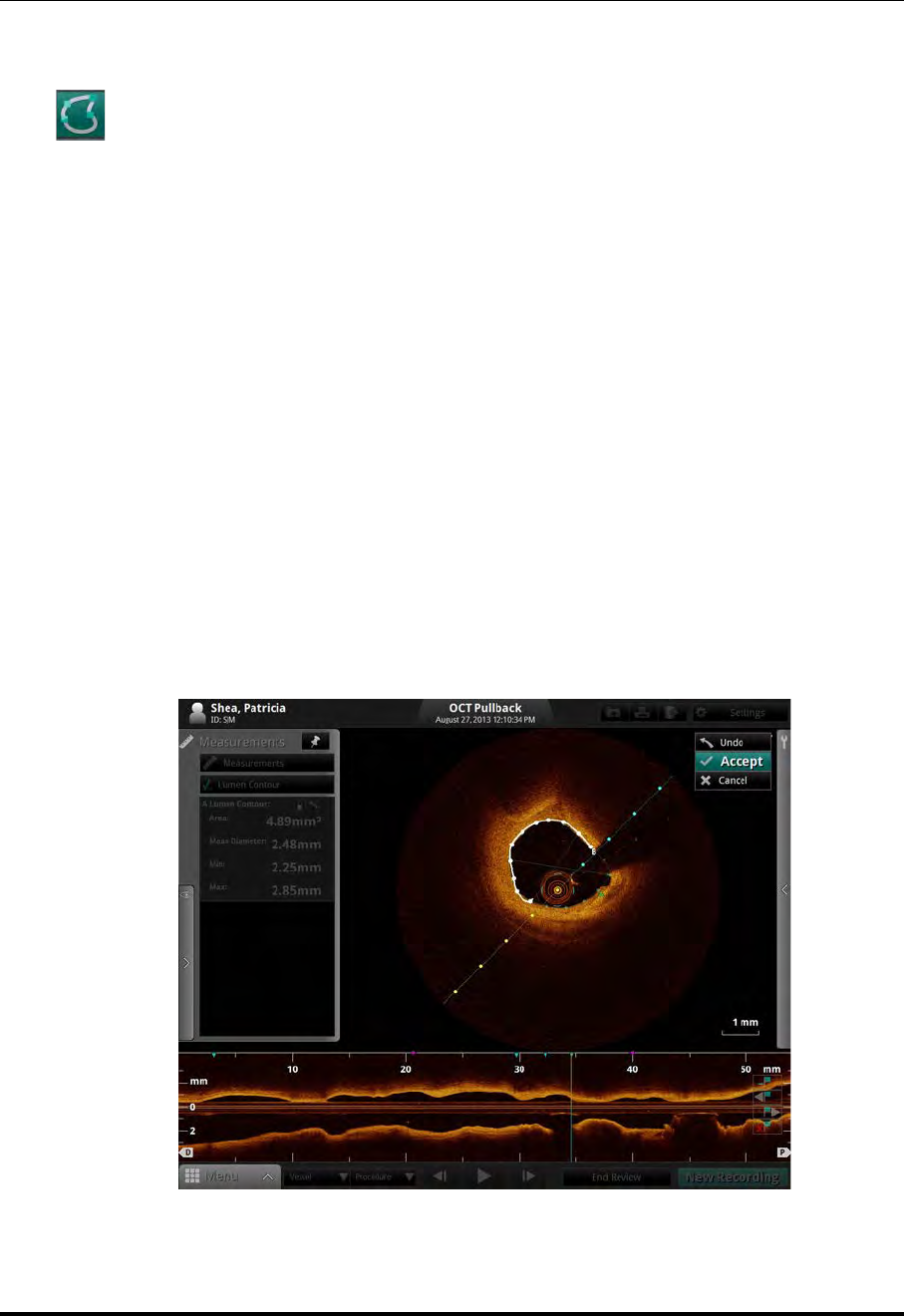
Measurements and Annotations
Area Measurements
St. Jude Medical
7-6 Part Number ARTUS100109403
Area Measurements
You can manually create a closed area trace of the lumen contour in the cross-sec-
tion view. The area is calculated using Green’s Theorem, and is displayed in the
frame in mm2 with the minimum and maximum diameter chords.
NOTE: If the Automatic MLA and %DS option is enabled and you are reviewing
a pullback recording, your system automatically adds a “Lumen Profile”
measurement on each frame.
NOTE: The minimum diameter chord has arrowheads that point inward (toward
the diameter chord). The maximum diameter chord has arrowheads that
point outward.
Making a Manual Area Measurement
1. Select the still image or paused recording that you want to measure.
2. Click on the Area - Multiple Points button (Figure 7-1). The cursor changes to a
pen.
3. Use the mouse to position the pen cursor at the desired starting point for the area in
the cross-section view and click to set the point.
Figure 7-3: Manual Area Measurement (in progress)

Measurements and Annotations
Area Measurements
ILUMIEN OPTIS System
Instructions for Use 7-7
NOTE: Click the Undo button to the left of the toolbar to delete the
most recent point added to the image.
4. Continue to add points with the pen cursor until you have accurately traced the area
to be measured. You can place as many points as you like around the border of the
desired area. At least three points are required.
NOTE: The first two points are connected by a straight line. When you place
subsequent points, the straight line becomes a smooth curve con-
necting all points but not closing the area until you click the Accept
button, or the last point is sufficiently close to the initial point for the
system to automatically complete the area. Placing more points
increases measurement accuracy.
NOTE: You must click either Accept or Cancel to complete the
measurement. Click Cancel to completely erase the mea-
surement.
5. Click the Accept button to the left of the toolbar to save the measurement, or click
the Cancel button to cancel it.
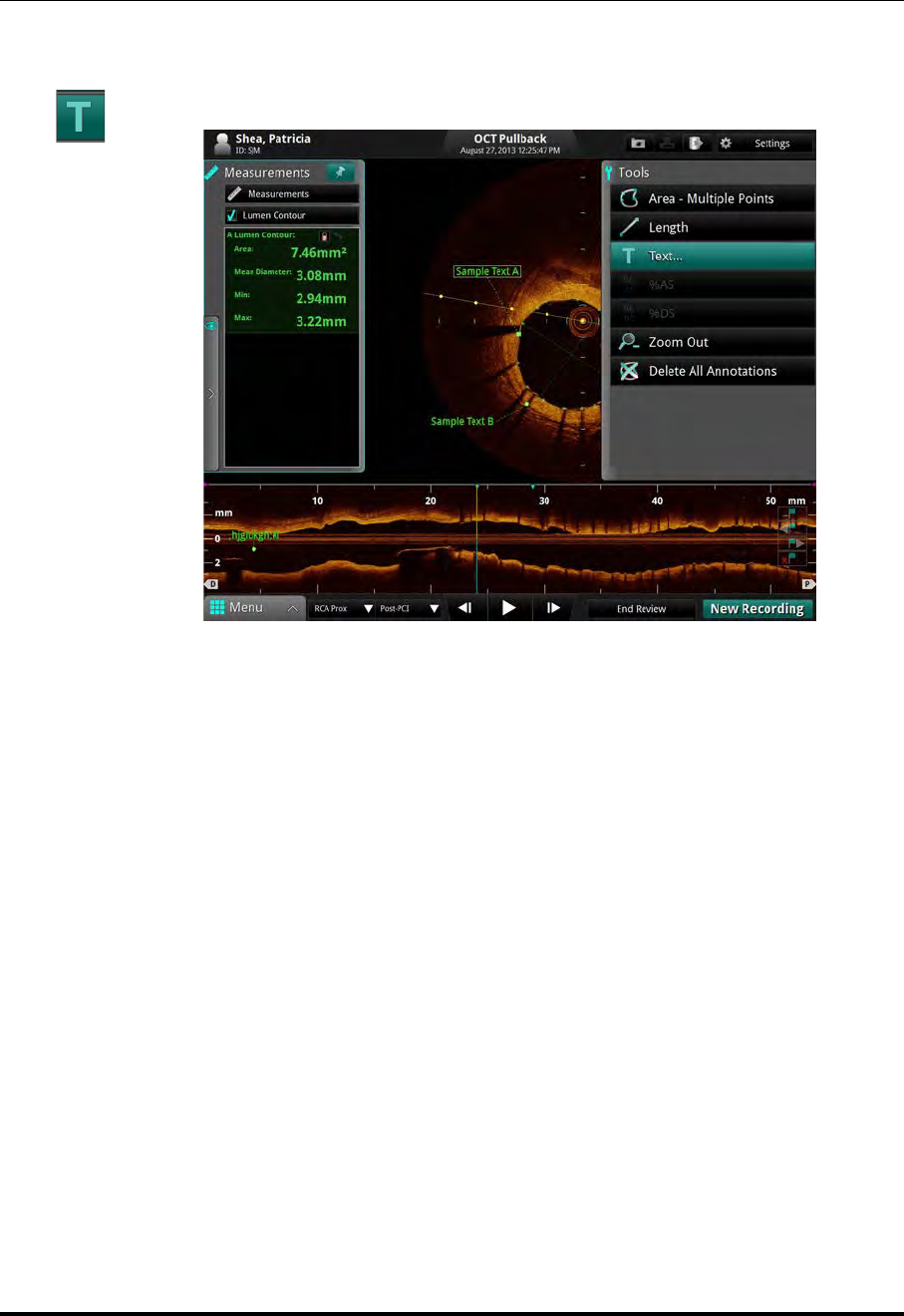
Measurements and Annotations
Adding Text Callouts
St. Jude Medical
7-8 Part Number ARTUS100109403
Adding Text Callouts
You can add text callouts to a single frame or to the entire recording.
Figure 7-4: Text Callouts
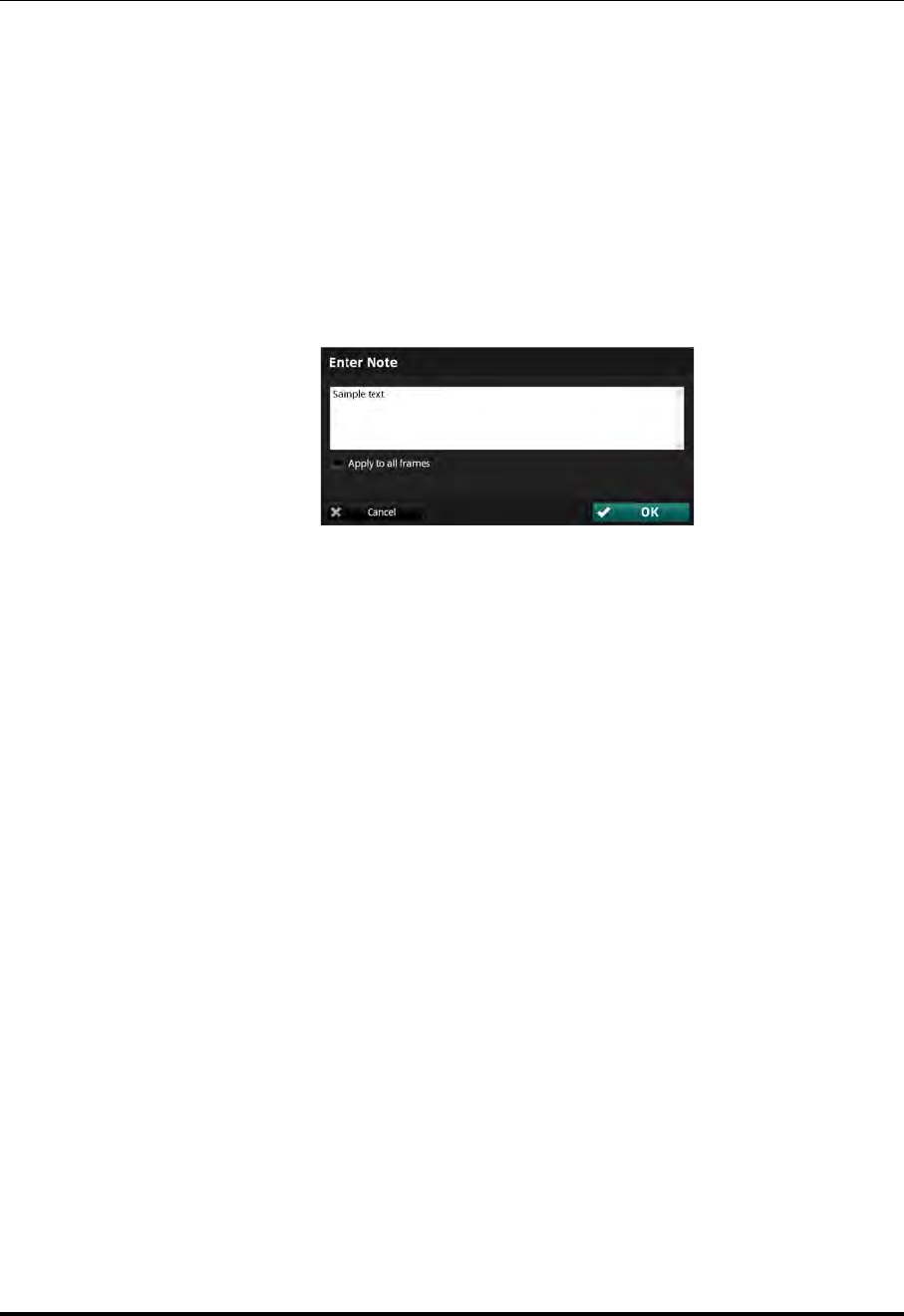
Measurements and Annotations
Adding Text Callouts
ILUMIEN OPTIS System
Instructions for Use 7-9
Adding Text Callouts
1. Select the still image or paused recording that you want to annotate with text.
2. Click on the Text... button (Figure 7-1).
The cursor changes to a Text marker (“A”).
3. Place the cursor where you want the text to be displayed.
The Enter Note menu (see Figure 7-5) appears.
4. Type the desired text into the box.
5. If you want to display the text on all frames, click the Apply to all frames check-
box. (Not applicable for text added in the L-Mode view.)
6. Click OK to approve the note or click Cancel to cancel the note.
The text appears, including a callout line beneath the text.
7. To change the position of the text on screen, click and drag the text to the desired
position.
8. To change the position of the callout line, click the end of the line and drag it to the
desired position.
Figure 7-5: Enter Note Dialog Box
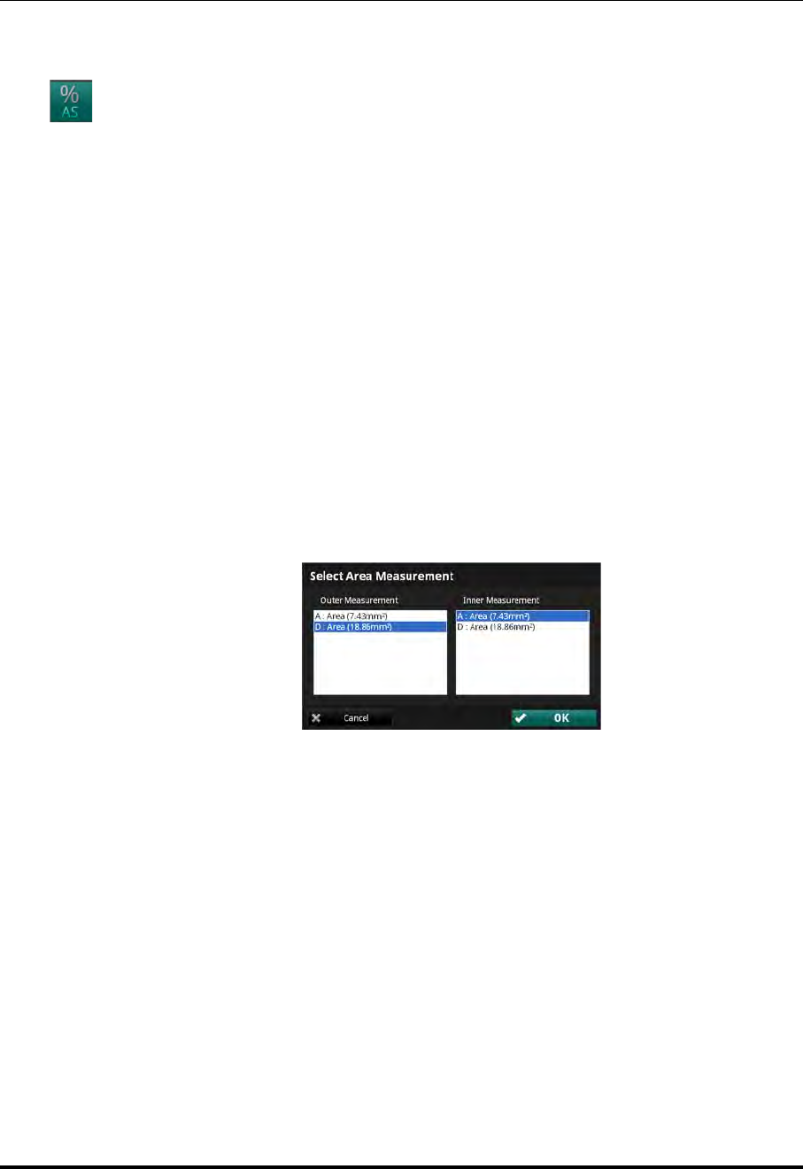
Measurements and Annotations
The %AS Calculation
St. Jude Medical
7-10 Part Number ARTUS100109403
The %AS Calculation
The %AS (Percent Area Stenosis) calculation calculates the percentage size of a
smaller area with relationship to a larger area, typically the area of the inner border
of a vessel compared to the area of the outer border.
Formula for %AS Calculation
%AS = (First Area-Second Area)/First Area * 100
To make this calculation, you must have two areas drawn on the current frame.
Make a %AS Calculation
1. Make an area measurement.
2. If necessary, make a second area measurement in the frame.
3. Click on the %AS button (Figure 7-1) to display the Select Area Measurement
dialog box.
4. In the Outer Measurement list, click the larger area measurement.
5. In the Inner Measurement list, click the smaller area measurement.
6. Click OK.
Figure 7-6: Select Area Measurement Dialog Box
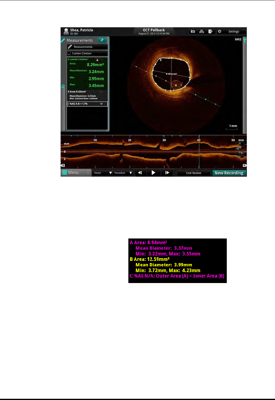
Measurements and Annotations
The %AS Calculation
ILUMIEN OPTIS System
Instructions for Use 7-11
The % Area Stenosis calculation is displayed immediately below the previous cal-
culations in the Annotation Panel as shown in Figure 7-7.
NOTE: If the second measurement you select is larger than the first measure-
ment, a %AS value will not be displayed. Instead, the Annotation
Panel displays an error message, similar to the one shown in Figure
7-8.
Figure 7-7: %AS Calculation
Figure 7-8: %AS Error Message
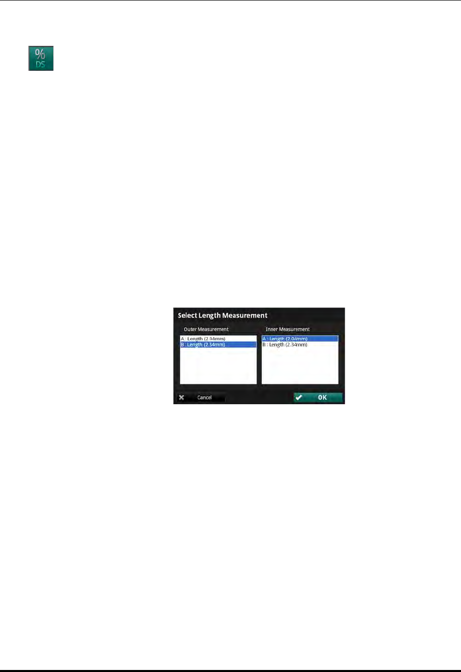
Measurements and Annotations
The %DS Calculation
St. Jude Medical
7-12 Part Number ARTUS100109403
The %DS Calculation
The %DS (Percent Diameter Stenosis) calculation calculates the percentage size of
a smaller length with relationship to a larger one, typically the diameter of the inner
border of a vessel compared to the diameter of the outer border.
Formula for %DS Calculation
%DS = (First Length-Second Length)/First Length * 100
To make this calculation you must first draw and specify two lengths, one for the smaller
diameter and one for the larger diameter.
Make a %DS Calculation
1. Make two length measurements in the current frame.
2. Click on the %DS button (Figure 7-1) to display the Select Length Measurement
dialog box.
3. In the Outer Measurement list, click the longer length.
4. In the Inner Measurement list, click the shorter length.
5. Click OK.
Figure 7-9: Select Length Measurement Dialog Box
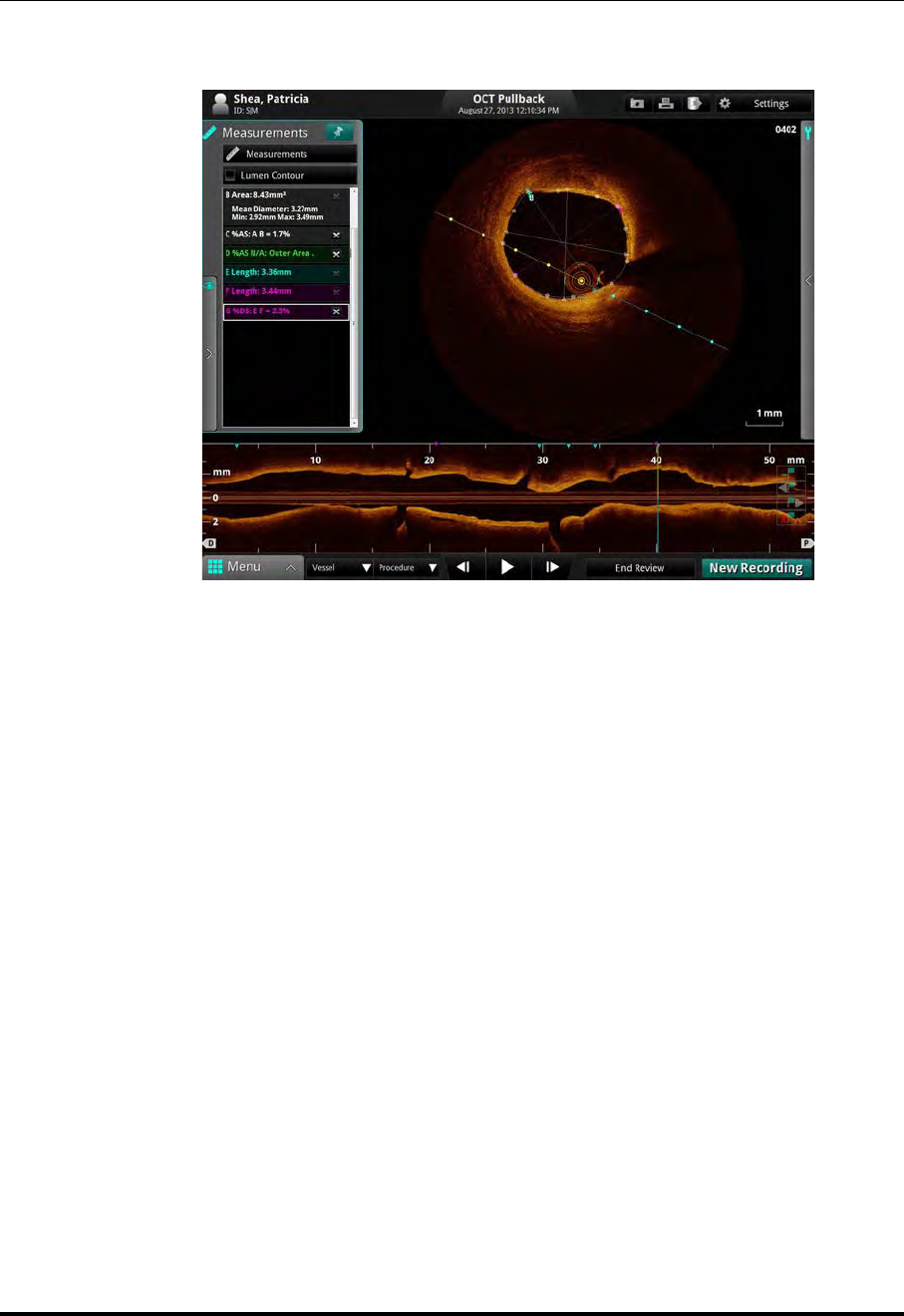
Measurements and Annotations
The %DS Calculation
ILUMIEN OPTIS System
Instructions for Use 7-13
The % Diameter Stenosis calculation is displayed immediately below the previous
calculations in the Annotations Panel, as shown in Figure 7-10.
NOTE: If the second measurement is larger than the first measurement you select,
a %DS value will not be displayed. Instead, the Annotation Panel displays
an error message, similar to the one shown in Figure 7-8 for %AS.
Figure 7-10: %DS Calculation

Measurements and Annotations
Field of View
St. Jude Medical
7-14 Part Number ARTUS100109403
Field of View
You can zoom out on a recording or still image in order to see the full lumen on a large
vessel, centered on the catheter.
NOTE: Using either Zoom function does not change the image data that is saved;
it merely changes the portion of the data that is displayed.
Increase/Decrease Field of View
Click to increase the field of view on the recording or still image. Click again to
return to normal image size.
NOTE: Depending on the current Flush Medium, the image may not occupy the
entire 10.5 mm diameter.
You can change the magnification of the zoomed field. See “Adjust Playback Settings”
on page 6-9 for more information.
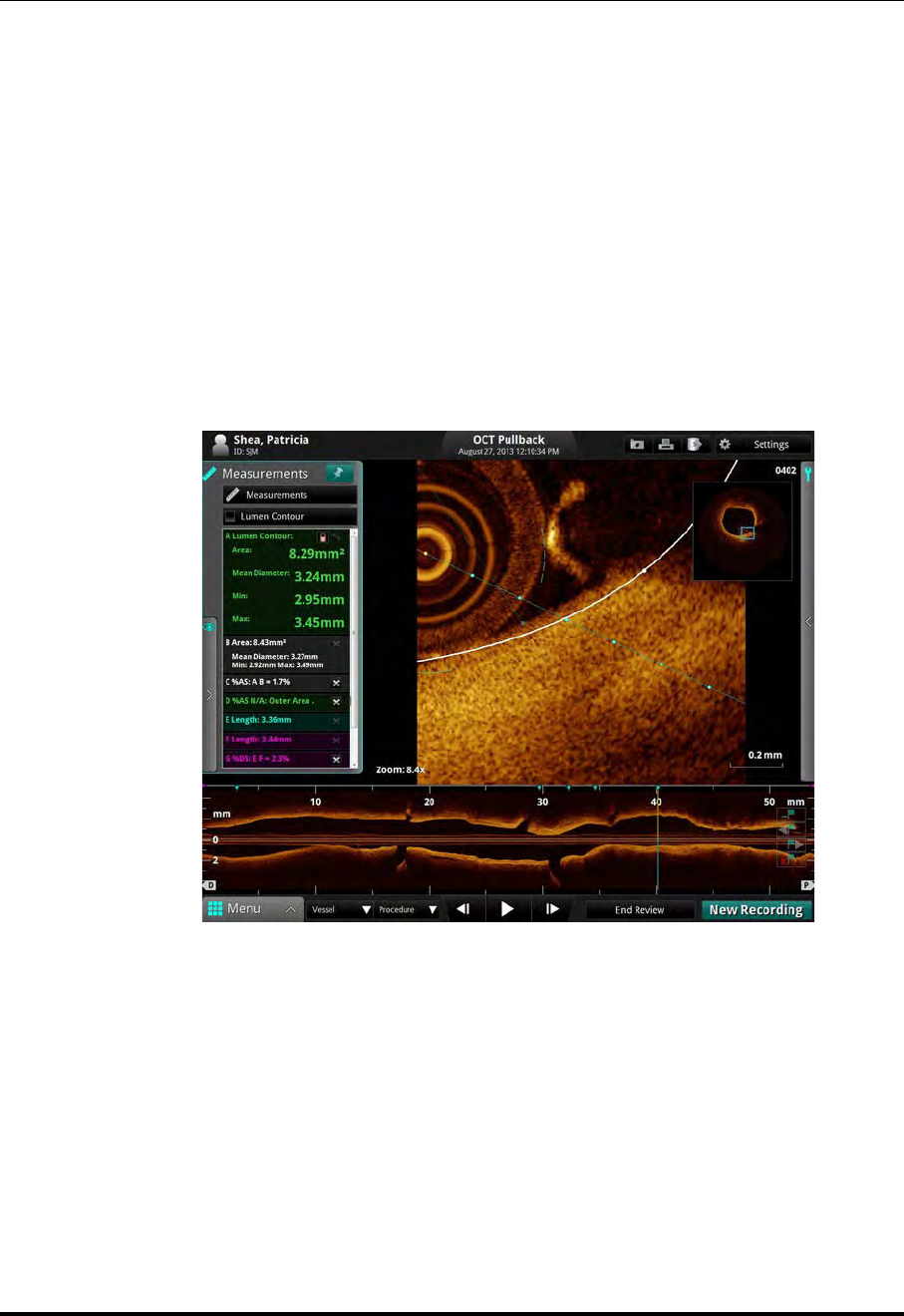
Measurements and Annotations
Field of View
ILUMIEN OPTIS System
Instructions for Use 7-15
Zooming In Manually
You can enlarge any section of the image manually.
NOTE: This magnification function cannot be used in the L-Mode display.
1. Place the cursor over the image area you want to enlarge.
2. Click and drag the mouse across an area to magnify it.
When you release the mouse, the system zooms in to the selected rectangle, dis-
playing the magnification factor used (ex. Zoom: 2.5x, see Figure 7-11).
The system adds an overall view of the image to the right.
3. To return to normal imaging, click anywhere in the zoomed image.
Figure 7-11: Zooming an Image
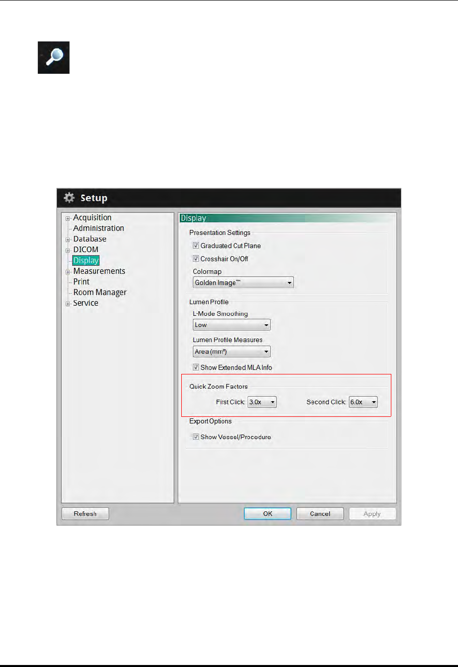
Measurements and Annotations
Field of View
St. Jude Medical
7-16 Part Number ARTUS100109403
Quick Zoom
The Quick Zoom feature provides two pre-set levels of magnification by
simply clicking on the image with the left mouse button. Hover over the
cross-sectional view so your cursor changes into a magnifying glass icon.
Click once to zoom in to the first level; click a second time to zoom in to the second level;
and then click again to return to normal magnification (1.0X).
The pre-set Quick Zoom Factors can be customized in the Settings menu Display
option. By default the First Click is set to 3.0X. The Second Click is set to 6.0X.
Figure 7-12: Setup Menu, Display Option

Measurements and Annotations
Editing Measurements and Annotations
ILUMIEN OPTIS System
Instructions for Use 7-17
Editing Measurements and Annotations
All measurements and annotations can be moved, deleted, or edited.
• Area and length measurements can be adjusted by moving or deleting control
points.
• Text annotations can be moved or deleted.
NOTE: When a measurement is changed, calculations that depend on that mea-
surement are updated automatically.

Measurements and Annotations
Editing Measurements and Annotations
St. Jude Medical
7-18 Part Number ARTUS100109403
Moving Individual Points
To move an individual point, click on the point and drag it to a new location.
NOTE: When you select a point, the point changes from a circle to a square, indi-
cating that it may now be moved.
NOTE: If you move a point on an automatically-generated Lumen Profile
contour, an arrow icon appears in the corner of the measurement
listed in the Annotations Panel. Click the arrow to reset the contour
on that frame back to the automatically-generated Lumen Profile contour.
See “Lumen Profile Display Option” on page 7-20 for more information.
Adding Points to a Multiple Point Area
To add additional points to a multiple point area, click on the curve between two points.
A new point will be added where you click.
NOTE: When you position the mouse over a location where a point can be added,
the cursor changes from an arrow to a hand.
Deleting Points from a Multiple Point Area
To delete selected points in a multiple point area, click on the desired point and press the
<Del> key on the keyboard.
NOTE: When you select a point, it changes from a circle to a square, indicating
that it may now be deleted.

Measurements and Annotations
Editing Measurements and Annotations
ILUMIEN OPTIS System
Instructions for Use 7-19
Deleting Individual Measurements or Text Callouts
NOTE: If a measurement is in use with a calculation (for example, an area
used by %AS), the individual measurement cannot be deleted until
the calculation is deleted.
To delete a measurement:
• Click on the “x” next to it in the Annotations Panel. The measurement is deleted.
To delete a distance measurement in the L-Mode:
1. Click on a distance measurement in the L-Mode to select it. A white box appears
around the label.
2. Press the <Del> key on the keyboard.
The distance measurement is deleted.
To delete a text callout:
1. Click on a text callout to select it. A white box appears around the text callout.
2. Press the <Del> key on the keyboard.
The text callout is deleted.
Deleting All Measurements and Text Callouts
Click to delete all measurements, calculations, and text callouts from this recording
or still image.
NOTE: Automatically generated Lumen Contours area measurements are not
deleted. If you have used the Lumen Profile function to calculate the min-
imum lumen area, that measurement is not deleted.

Measurements and Annotations
Lumen Profile Display Option
St. Jude Medical
7-20 Part Number ARTUS100109403
Lumen Profile Display Option
The system automatically creates a trace of the lumen contour on
each frame.
NOTE: Lumen Profile is not available with still images or station-
ary recordings.
L-Mode view must be turned on in order to use the Lumen Profile
display option.
Remove the check from the Measurements checkbox to hide the
lumen contour trace and corresponding measurements.
The Lumen Profile display opens with Minimum Lumen Area (MLA) and a percent ste-
nosis graph (%AS or %DS) turned on:
•MLA displays the Minimum Lumen Area controls and values for this record-
ing.
•%DS shows how the mean diameter changes along the L-Mode. It can also
display the %DS at MLA and proximal and distal reference points.
•%AS shows how the lumen area changes along the L-Mode. It can also dis-
play the %AS at MLA and proximal and distal reference points.
NOTE: For information on displaying extended MLA info, see Table 10-12 on
page 10-21.
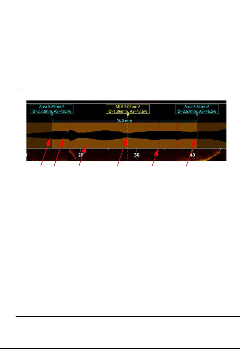
Measurements and Annotations
Lumen Profile Display Option
ILUMIEN OPTIS System
Instructions for Use 7-21
Lumen Profile Display With MLA Controls Overview
CAUTION: It is the user’s responsibility to confirm the lumen contour on each
frame, and to make adjustments if necessary.
Red frames indicate low confidence in the detected contour. If the
MLA frame is in the vicinity of a low confidence region, the system
displays “?.??” for the MLA values. If the MLA values are “?.??,” the
contour on the MLA frame must be reviewed, edited if necessary, and
accepted before it can be displayed.
Table 7-2: MLA Controls
ADistal and Proximal Reference Frames : Move these to set the range for MLA calcula-
tion. The system’s search for a minimum lumen area occurs on frames between the distal
and proximal reference frames.
See Table 7-3 on page 7-22 for more information on calculations. See Table 10-12 on
page 10-21 for showing extended MLA info.
• If %DS is selected in the Lumen Profile, the reference frames and the MLA frame dis-
play the percent diameter stenosis at each end of the range.
• If %AS is selected, the reference frames and the MLA frame display the percent area
stenosis at each end of the range.
BThe lumen area is colored black.
CWhere the system has high confidence in the contour of the lumen area, or where the con-
tour has been accepted by the user, the section is colored brown.
DCalculated MLA : The dashed line indicates the position of the minimum lumen area
between the distal and proximal reference frames (A).
EWhere the system has low confidence in the contour of the lumen area, the section is col-
ored red. These frames are not considered in the MLA search. If these frames are within
the range where MLA is calculated, you must go to the MLA frame and confirm the con-
tour.
BCEA D A

Measurements and Annotations
Lumen Profile Display Option
St. Jude Medical
7-22 Part Number ARTUS100109403
Table 7-3: Lumen Profile %AS and %DS Calculations
When Lumen Profile set to %DS... When Lumen Profile set to %AS...
Stenosis calculations
of the MLA frame
compared to average
of distal and proximal
references (value
listed above the MLA
frame):
%DS = 100 * (DREF - DMLA) / DREF
where DREF is the average of the
Distal Reference’s mean diameter
and the Proximal Reference’s mean
diameter. DMLA is the MLA’s mean
diameter.
%AS = 100 * (AREF - AMLA) / AREF
where AREF is the average of the
Distal Reference’s area and the
Proximal Reference’s area. AMLA is
the Minimum Lumen Area.
Stenosis calculations
of the MLA frame
compared to individ-
ual distal and proxi-
mal references (values
listed above the D or P
reference frames):
%DS = 100 * (DD or P - DMLA) / DD or P
where DD or P is the Distal
Reference’s mean diameter or the
Proximal Reference’s mean
diameter. DMLA is the MLA’s mean
diameter.
%AS = 100 * (AD or P - AMLA) / AD or P
where AD or P is the Distal
Reference’s area or the Proximal
Reference’s area. AMLA is the
Minimum Lumen Area.

Measurements and Annotations
3D Display Option
ILUMIEN OPTIS System
Instructions for Use 7-23
3D Display Option
Click the Advanced Display button to create a 3D representation of the recording.
Clicking the Advanced Display button toggles-through the options: Off, 3D Tissue, and
3D Lumen. You can also select the desired option by clicking the button next to it.
NOTE: You cannot add or change measurements or annotations in the
cross-section view or 3D Display while 3D Display is on. You can add
annotations and distance measurements to the L-Mode view only.
3D Display is not available with still images or stationary recordings.
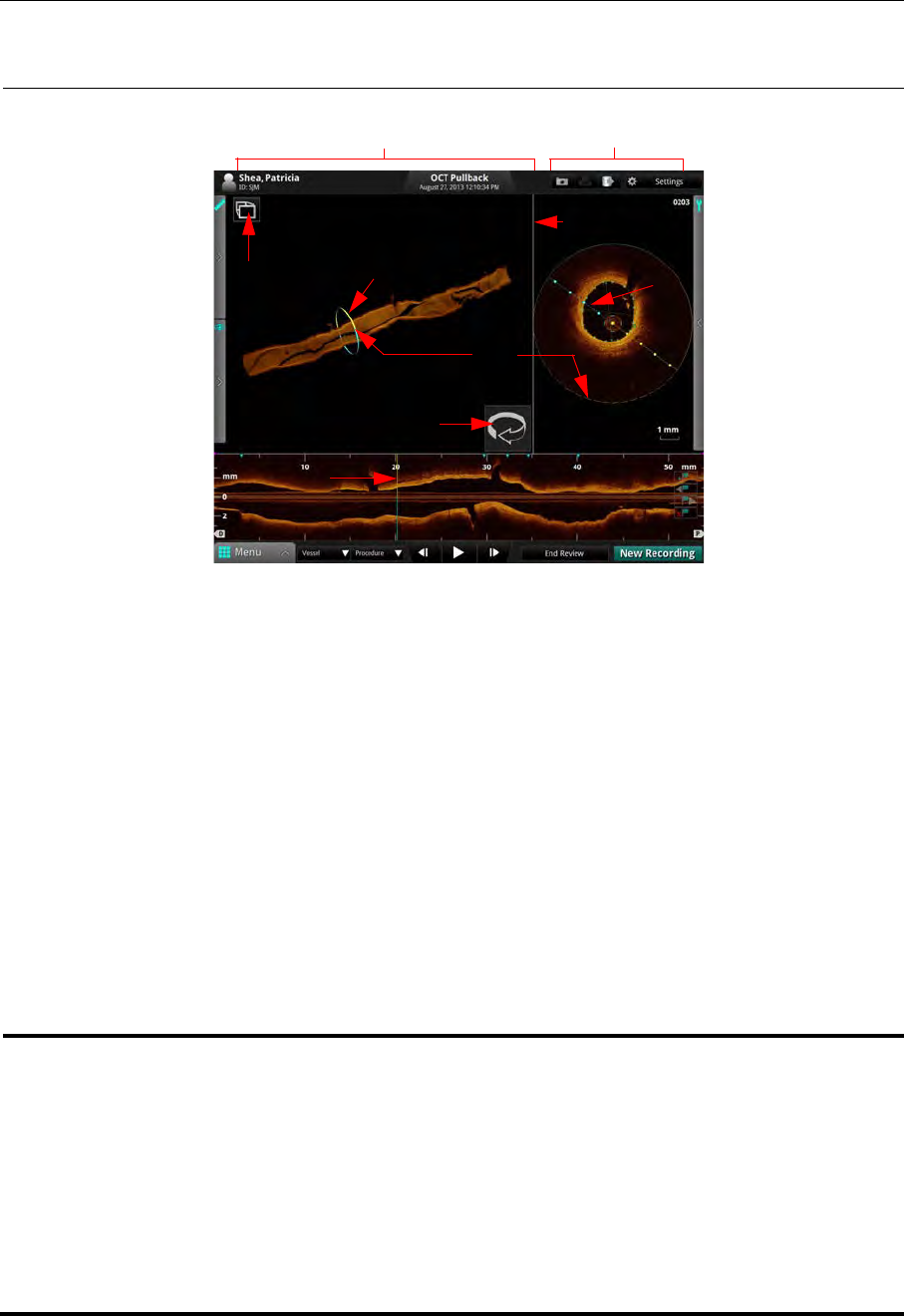
Measurements and Annotations
3D Display Option
St. Jude Medical
7-24 Part Number ARTUS100109403
3D Tissue Controls Table 7-4: 3D Tissue Controls
AView Mode : Click to toggle between Window mode (shown above) and Full Screen Mode.
BCurrent Frame Indicator (3D View) : Scroll the mouse wheel (or twist the Navagation Con-
troller) to change the cut plane as shown in the L-Mode.
CCut Plane Rotation Hotspot : Place the cursor over the Hotspot and rotate the mouse wheel to
change the cut plane as shown in the L-Mode.
DCurrent Frame Indicator (L-Mode View) : Click and drag to change the frame shown.
EThe solid lines in the cross-sectional view represent the rendered half of the vessel image. The
dashed lines in the cross-sectional view represent the open, or un-rendered, half of the vessel
image. The blue and yellow colors are for location referencing among the views.
FClick and drag the divider bar side to side to change the size of 3D Display versus cross-section
view.
GCut Plane Indicator : The cut-plane is shown as a solid line in the cross-sectional view Click
and drag this to change the lateral view shown in the L-Mode display.
NOTE: To zoom you can either left click in the 3D Display window for Quick Zoom factors or
right-click and drag up or down, left or right to adjust zoom.
A
C
B
3D Display Cross-Section View
(Tissue
Option
Shown)
D
F
E
G
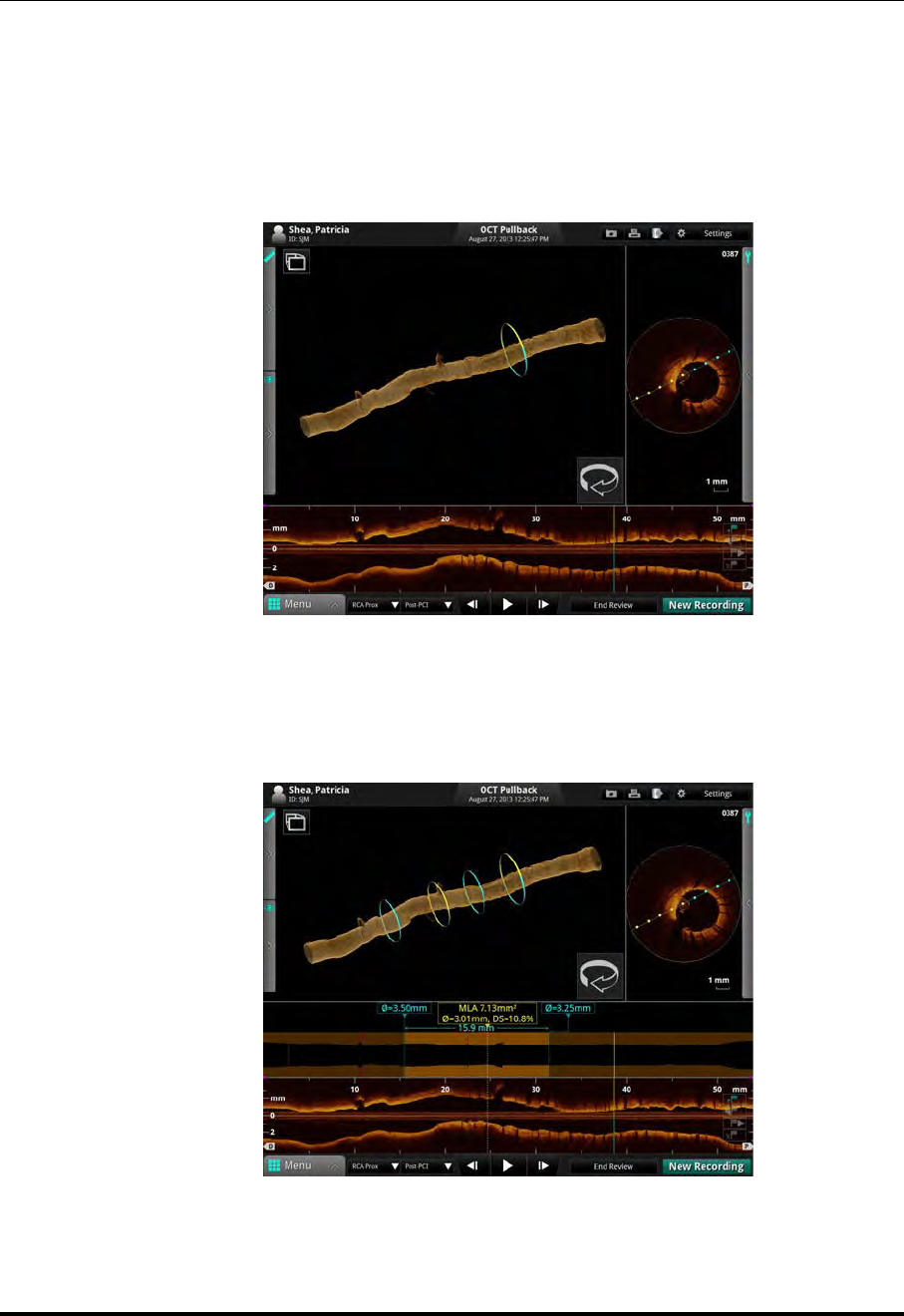
Measurements and Annotations
3D Display Option
ILUMIEN OPTIS System
Instructions for Use 7-25
3D Display with Lumen
NOTE: If the 3D Lumen setting is turned on, the 3D Tissue setting is turned off,
and vice-versa. Selecting one deselects the other.
The 3D Lumen setting adds a 3D representation of the lumen contours drawn on each
frame.
NOTE: If you have the MLA setting turned on under the Lumen Profile display
and you have selected 3D Lumen (shown) or 3D Tissue, the distal, prox-
imal, and MLA frames are displayed.
Figure 7-13: 3D Display with Lumen
Figure 7-14: MLA Frames in 3D
Distal
Proximal
MLA

Measurements and Annotations
3D Display Option
St. Jude Medical
7-26 Part Number ARTUS100109403
Limitations of 3D Display
Please be aware of the following limitations of the 3D Display Option:
• Although a vessel may curve, the 3D Display view always appears straight because
of the limitations of reconstruction.
• Artifacts caused by the relative motion of the catheter and the vessel often result in
a saw-toothed appearance of the reconstruction and can lead to misinterpretation by
inexperienced users.
• Shortening or lengthening artifacts in the 3D Display reconstruction may occur due
to the relative motion of the imaging catheter with respect to the coronary artery
caused by the patient’s heart motion.

ILUMIEN OPTIS System
Instructions for Use 8-1
Exporting, Importing, and Managing Files 8
CAUTION: Please note St. Jude Medical makes no representation or warranty
that use of the OPTIS INTEGRATED System complies with applicable
privacy, security and confidentiality laws, but encourages you to
assess your own risk as you use, disclose, control, process or transfer
patient health information with the OPTIS INTEGRATED System.

Exporting, Importing, and Managing Files
Compatible Transfer Media and USB Devices
St. Jude Medical
8-2 Part Number ARTUS100109403
Compatible Transfer Media and USB Devices
The following sections list the supported media formats.
If you experience problems with a specific type of CD/DVD or USB device, contact St.
Jude Medical for recommendations.
Optical Media
The system can export files through the CD/DVD drive. Table 8-1 lists the supported disc
formats and describes whether they can be erased and/or appended.
If you try to export files to a CD-RW that already has data on it, an alert message appears.
Click Yes to export your files to this disc, or click No to cancel the export.
If you try to export files to a DVD+RW, DVD-RW, or DVD-RAM that already has data
on it, an alert message appears. Click OK to erase the disc and export your files, or click
Cancel to cancel the export.
If you try to export files to a disc that cannot be formatted or appended (such as DVD+R
DL and DVD-R DL), an alert message appears. Insert a new disc to continue, or click
Cancel to cancel the export.
USB Connected Media
The system can export files through the USB port. Any USB hard drive or Flash Drive
that meets the USB 2.0 Specification and is supported by Windows 7 SP1 may be used.
WARNING: Inside the catheterization lab only port-powered USB drives may be
connected to the USB port. Connecting externally powered devices to
Table 8-1: Optical Media Characteristics
Media Capacity Can Erase Can Append
CD-R 737 MB X
CD-RW 737 MB X X
DVD+R 4.7 GB X
DVD+RW 4.7 GB X
DVD+R Dual Layered 8.5 GB X
DVD-R 4.7 GB X
DVD-RW 4.7 GB X
DVD-R Dual Layered 8.5 GB
DVD-RAM 4.7 GB X

Exporting, Importing, and Managing Files
Compatible Transfer Media and USB Devices
ILUMIEN OPTIS System
Instructions for Use 8-3
the USB port in the patient vicinity may compromise electrical isola-
tion and cause patient injury.
NOTE: Outside the catheterization lab, IEC 60950-compliant, externally powered
USB hard drives may be connected to the USB port.

Exporting, Importing, and Managing Files
File Formats
St. Jude Medical
8-4 Part Number ARTUS100109403
File Formats
Files can be exported in native file format (raw OCT format), a standard graphic file for-
mat (standard format), or DICOM format. Exported files can be saved on a CD/ DVD or
external USB device, or exported to a DICOM storage server. You can choose whether to
delete files after transfer or keep them on the system.
About Native (Raw OCT) Format
If you export in native (raw OCT) file format, every feature of the OCT file will be
exported, and the files can be imported into another ILUMIEN or OPTIS INTEGRATED Sys-
tem or an Offline Review Workstation (ORW) and reviewed and manipulated there. An
exported OCT file contains exactly the same data as the original file, including any mea-
surements and annotation additions, all patient information associated with each file, and
system diagnostic information to help diagnose possible image quality problems.
Note the following:
• Native (raw OCT) files can be reviewed and manipulated only with an ILUMIEN
System, an OPTIS INTEGRATED System, or an ORW. They cannot be accessed with
any other systems or software.
• Native (raw OCT) files are large; exporting to CD/DVD may require many discs.
About DICOM Format
For a multiple-frame recording using DICOM format stored on a network server, the
maximum resolution is 800 x 800.

Exporting, Importing, and Managing Files
File Formats
ILUMIEN OPTIS System
Instructions for Use 8-5
About Standard Format
If you export in standard file formats (AVI, compressed AVI, or Multi-page TIFF for
recordings; JPEG, TIFF, or BMP for images), the images can be used in computer appli-
cations outside the system, but cannot be imported into an ILUMIEN System, an OPTIS
INTEGRATED System, OPTIS MOBILE System, or an ORW.
NOTE: For standard format multiple-file exports, the same limitations apply as
described in “Image Format and Size in Standard Formats”. Just as when
exporting a single file, you can choose the size and format.

Exporting, Importing, and Managing Files
Image Format and Size in Standard Formats
St. Jude Medical
8-6 Part Number ARTUS100109403
Image Format and Size in Standard Formats
When exporting files in standard formats, the system gives you several choices of format
and file resolution (size). When making these choices, keep in mind the following:
File Size
• File size is dependent on resolution; the lower the resolution, the smaller the file.
• Decreasing resolution makes the resulting image grainier, but no quantitative
data, annotations or measurements are lost.
• Increasing resolution results in higher image quality in the exported file. For
a file that is a single frame (from a captured image, a paused image, or from
a recording that has been edited down to only one frame), the maximum res-
olution for export is 2048 x 2048.
• For a multiple-frame recording, the maximum resolution is 1024 x 1024.
• It is best to select the resolution that will actually be used in the intended applica-
tion. When images are enlarged or reduced by the system, the maximum useful
information is preserved. External applications may not apply the same diligence
when enlarging or reducing an image.
Standard File Format
• The system can export recordings as either AVI, compressed AVI, or Multi-page
TIFF format.
• Most computers include standard players that will play AVI format files.
• The Compressed AVI and Multi-page TIFF formats require that special play-
ers for these formats be installed on the computer you will use to review the
files.
• The system can export still images as either JPEG, TIFF, or BMP.
• TIFF and BMP files are high resolution bit-map files with large file size.
• JPEG files are compressed image files designed especially for viewing in a
computer application. They are significantly smaller than TIFF or BMP files,
and are typically the best choice for slide shows or other applications where
the files will be viewed on a computer monitor.

Exporting, Importing, and Managing Files
Exporting Files During a Review
ILUMIEN OPTIS System
Instructions for Use 8-7
Exporting Files During a Review
During review, you can use the Export button to export the current recording or still
image to Native (Raw) format, DICOM format, or standard file formats.
NOTE: The Export button is unavailable while a recording is playing. To export
from a recording, pause the recording before clicking the Export button.
All edits, including measurements, calculations, annotations and zoom, are included with
the recording or still image when it is exported (see Chapter 7 “Measurements and Anno-
tations”).
CAUTION: If you are exporting to standard formats, make all measurements
BEFORE exporting. Using non-OCT software to measure standard
format images will not produce accurate measurements.
CAUTION: Do not use images that have been exported to JPEG or Compressed
AVI formats for clinical decision making. These formats use compres-
sion methods that may degrade the image quality.
NOTE: Editing images stored on the system does not change the underlying image
data in any way. All unedited data taken during the procedure is always
preserved and can be reviewed without the changes.
NOTE: If the system displays an error message during export, a restart may be
required. If necessary, click OK to restart the system. If the error condition
persists, export the recording from the Patient Summary menu, or reduce
the resolution for the export of the recording. See “Exporting Files from
the Patient Summary Menu” on page 8-14 for more information.
Figure 8-1: Export Button (OCT)
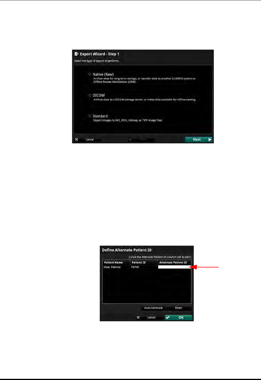
Exporting, Importing, and Managing Files
Exporting Files During a Review
St. Jude Medical
8-8 Part Number ARTUS100109403
Exporting Files in Native (Raw) Format
1. Click the Export button.
The Export Wizard opens (see Figure 8-2).
2. Click to select Native (Raw), and click Next.
3. If you need to remove patient identifying information from the exported files, add
a check to the Anonymize checkbox.
• If you have added a check to the Anonymize checkbox, you can also add an
alternate means of identifying the patient. Click the Alternate PIDs... button
to open the Define Alternate Patient ID menu:
• Click in the Alternate Patient ID column and type an alternate ID tag
for this patient.
• Click the Auto-Generate button to add an alternate ID generated by the
system. Click the Reset button to clear the ID generated by the system.
Figure 8-2: The Export Wizard - Step 1
Figure 8-3: Define Alternate Patient ID Menu

Exporting, Importing, and Managing Files
Exporting Files During a Review
ILUMIEN OPTIS System
Instructions for Use 8-9
•Click OK to approve the change and close the menu, or Cancel to
return to previous settings and close the Define Alternate Patient ID
menu.
4. Click to set the System File Options for the file(s) that you are exporting:
•Leave Unchanged - the files are exported, but the original files in the System
are not changed.
•Mark as Archived - the files are exported, and marked as archived.
•Remove when Complete - the files are deleted from the System once the
export is complete.
5. Click Next to approve the settings and open the next page of the Export Wizard.
NOTE: Click Back to return to the previous page, or click Cancel to exit the
Export Wizard without exporting files.
6. Click to select an Export Destination:
NOTE: If an output device is not available, that option cannot be selected.
NOTE: Check that the Free space in the Drive Capacity section is large
enough to save the files that are being exported.
•Click CD/DVD to export to a CD/DVD.
If the inserted CD/DVD is blank, you can edit the name in the Volume Label
field.
•Click External Drive to export to an external USB device.
If necessary, click the External Drive selection box to select the correct drive
location from the drop-down menu.
Click the Ellipsis (...) button to the right of the Path selection box to browse
for a specific folder on the device.
7. Click Next to approve the settings and open the next page of the Export Wizard.
The next page of the Export Wizard opens. The menu shows a summary of Export
Information.
8. Click Export to export the selected files.
The export begins. If necessary, click Cancel to stop the export in progress.

Exporting, Importing, and Managing Files
Exporting Files During a Review
St. Jude Medical
8-10 Part Number ARTUS100109403
9. When complete, click Done to close the Export Wizard.
Exporting Files in DICOM Format
1. Click the Export button.
The Export Wizard opens (see Figure 8-2).
2. Click to select DICOM, and click Next.
NOTE: If you are reviewing a single frame instead of a recording, skip to Step 5
3. Click to select the material to be exported:
•Pullback
• Current Frame
• Bookmarked Frames - This choice is unavailable if there are no book-
marked frames in the recording.
4. Click Next to approve the settings and open the next page of the Export Wizard.
NOTE: Click Back to return to the previous page, or click Cancel to exit the
Export Wizard without exporting files.
5. If you need to remove patient identifying information from the exported files, add
a check to the Anonymize checkbox.
6. Click to set the System File Options for the file(s) that you are exporting:
•Leave Unchanged - the files are exported, but the original files in the System
are not changed.
•Mark as Archived - the files are exported, and marked as archived.
7. Click Next to approve the settings and open the next page of the Export Wizard.
8. Click to select an Export Destination:
NOTE: If an output device is not available, that option cannot be selected.
NOTE: Check that the Free space in the Drive Capacity section is large
enough to save the files that are being exported.
•Click CD/DVD to export to a CD/DVD.

Exporting, Importing, and Managing Files
Exporting Files During a Review
ILUMIEN OPTIS System
Instructions for Use 8-11
If the inserted CD/DVD is blank, you can edit the name in the Volume Label
field.
•Click External Drive to export to an external USB device.
If necessary, click the External Drive selection box to select the correct drive
location from the drop-down menu.
Click the Ellipsis (...) button to the right of the Path selection box to browse
for a specific folder on the device.
•Click Remote Store to export to a network DICOM Server.
NOTE: The Remote Store option is enabled only if the DICOM net-
work connection has been configured on the DICOM tab of
the Setup dialog box (see Chapter 10 “User Interface Refer-
ence”for more information on DICOM settings).
9. Click Next to approve the settings and open the next page of the Export Wizard.
The next page of the Export Wizard opens, showing a summary of Export Infor-
mation.
10. Click Export to export the selected files.
The export begins. If necessary, click Cancel to stop the export in progress.
11. When complete, click Done to close the Export Wizard.

Exporting, Importing, and Managing Files
Exporting Files During a Review
St. Jude Medical
8-12 Part Number ARTUS100109403
Exporting Files in Standard Formats
NOTE: 3D reconstructions cannot be exported in Standard formats.
1. Click the Export button.
The Export Wizard opens (see Figure 8-2).
2. Click to select Standard, and click Next.
NOTE: If you are reviewing a single frame instead of a recording, skip to Step 5.
3. Click to select the material to be exported:
• Pullback
• Current Frame
• Bookmarked Frames - This choice is unavailable if there are no book-
marked frames in the recording.
4. Click Next to approve the settings and open the next page of the Export Wizard.
NOTE: Click Back to return to the previous page, or click Cancel to exit the
Export Wizard without exporting files.
5. Click to set the resolution and file format.
6. Click Next to approve the settings and open the next page of the Export Wizard.
7. Verify the names of the files that are being exported. If necessary, double-click a
filename and edit it using the keyboard.
8. Click Next to approve the settings and open the next page of the Export Wizard.
9. Click to select an Export Destination:
NOTE: If an output device is not available, that option cannot be selected.
NOTE: Check that the Free space in the Drive Capacity section is large
enough to save the files that are being exported.
•Click CD/DVD to export to a CD/DVD.
If the inserted CD/DVD is blank, you can edit the name in the Volume Label
field.

Exporting, Importing, and Managing Files
Exporting Files During a Review
ILUMIEN OPTIS System
Instructions for Use 8-13
•Click External Drive to export to an external USB device.
If necessary, click the External Drive selection box to select the correct drive
location from the drop-down menu.
Click the Ellipsis (...) button to the right of the Path selection box to browse
for a specific folder on the device.
10. Click Next to approve the settings and open the next page of the Export Wizard.
The next page of the Export Wizard opens. The menu shows a summary of Export
Information.
11. Click Export to export the selected files.
The export begins. If necessary, click Cancel to stop the export in progress.
12. When complete, click Done to close the Export Wizard.
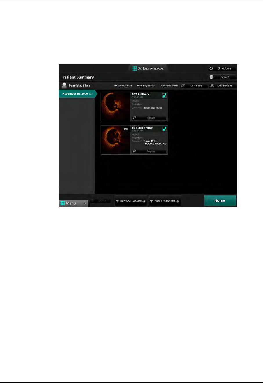
Exporting, Importing, and Managing Files
Exporting Files from the Patient Summary Menu
St. Jude Medical
8-14 Part Number ARTUS100109403
Exporting Files from the Patient Summary Menu
You can export files from the Patient Summary menu.
1. In the Patient Summary menu, add a check to the checkbox of each file that you
want to export.
A white border appears around each record that is selected.
NOTE: In the Patient Summary menu, you can select multiple files from
the same date, but not from different dates. Within the Export Wiz-
ard, you can select additional files from different dates and different
patients.
NOTE: To deselect a file, clear the check from the checkbox. The check and
white border disappear to indicate that the file is no longer selected.
2. Click the Export button at the top of the screen.
The Export Wizard opens (see Figure 8-2).
3. Click to select an export format, and click Next.
The next page of the Export Wizard opens.
Figure 8-4: Highlighted Records

Exporting, Importing, and Managing Files
Exporting Files from the Patient Summary Menu
ILUMIEN OPTIS System
Instructions for Use 8-15
4. To filter the list, click the All, Unarchived, or New since last archive button.
5. If necessary, add a check to the checkbox of any other recording to be exported.
• Add a check to the checkbox of patient to select all recordings for that
patient.
• Add a check to the checkbox of the first entry in the list to select all
recordings.
6. Click Next to approve the list of files for export and open the next page of the
Export Wizard.
• If you are exporting in Native (Raw) format, refer to Step 3 in “Exporting
Files in Native (Raw) Format” on page 8-8 to continue the export.
• If you are exporting in DICOM format, refer to Step 5 in “Exporting Files in
DICOM Format” on page 8-10 to continue the export.
• If you are exporting in standard formats, refer to Step 5 in “Exporting Files in
Standard Formats” on page 8-12 to continue the export.
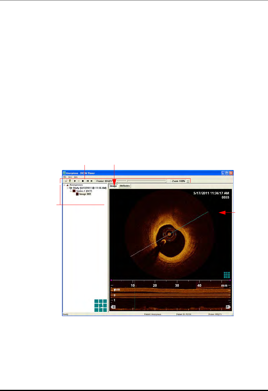
Exporting, Importing, and Managing Files
Using Exported Standard Format Recordings
St. Jude Medical
8-16 Part Number ARTUS100109403
Using Exported Standard Format Recordings
The system can export recordings as either AVI, compressed AVI, or Multi-page TIFF
format. Most computers include standard players that will play AVI format files. How-
ever, the Compressed AVI format and the Multi-page TIFF formats require that you have
special players installed on your computer to review the files.
St. Jude Medical DICOM Viewer
When an image file is exported to a CD/DVD in the DICOM format, the St. Jude Medical
DICOM Viewer (shown in Figure 8-5) is also included on the CD/DVD. This DICOM
CD/DVD can then be freely distributed and used with any Microsoft Windows computer
(the CD/ DVD is configured to automatically launch the viewer when it is inserted into
the drive). The St. Jude Medical DICOM Viewer may only be used to view St. Jude Med-
ical generated DICOM images on a St. Jude Medical DICOM CD/DVD. If this CD/DVD
is to be used in a public forum, the Anonymous option should be used when exporting the
image using the system.
Figure 8-5: St. Jude Medical DICOM Viewer - Image View
Viewer Controls
File Viewer
Directory Tree
Image View Selected
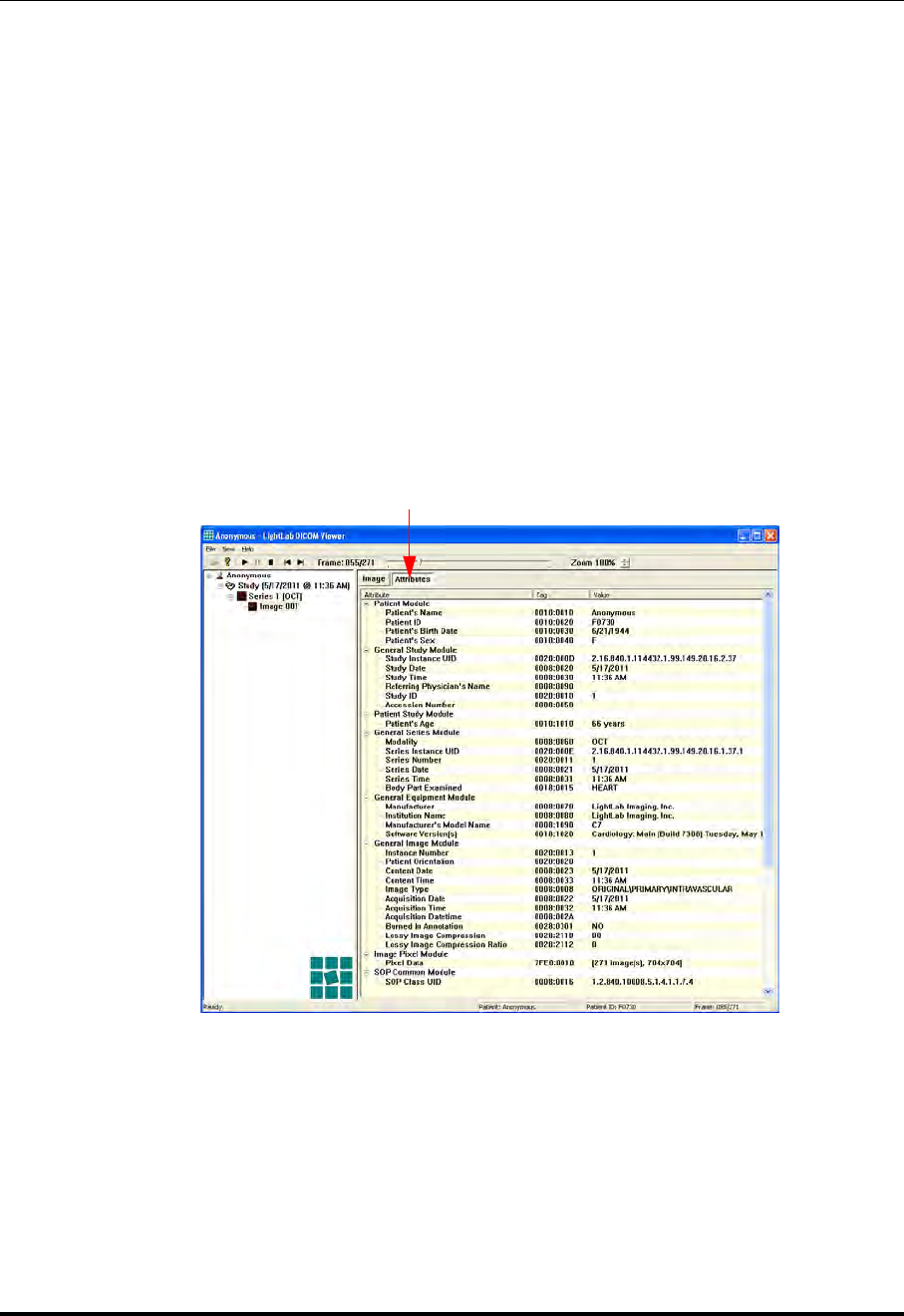
Exporting, Importing, and Managing Files
Using Exported Standard Format Recordings
ILUMIEN OPTIS System
Instructions for Use 8-17
The St. Jude Medical DICOM Viewer window contains three different sections:
•Viewer Controls - Provides control over the viewer and the active image.
•Directory Tree - This tree lists the patient, study, series, and image hierarchy con-
tained in the DICOMDIR file on the CD/DVD. Individual images may be loaded by
clicking on the image item in the tree.
•File Viewer - Provides two tabs:
•Image tab - Displays the image currently selected in the DICOM Directory
Tree (see Figure 8-5). If the image is a recording, playback may be controlled
using the playback buttons in the Viewer Controls at the top of the viewer.
The image may also be zoomed in or out using the Zoom feature in the tool-
bar.
•Attributes tab - Displays a list of all DICOM modules and attributes con-
tained in the currently selected image (see Figure 8-6).
Figure 8-6: St. Jude Medical DICOM Viewer - Attributes View
Attributes View Selected

Exporting, Importing, and Managing Files
Using Exported Standard Format Recordings
St. Jude Medical
8-18 Part Number ARTUS100109403
The St. Jude Medical DICOM files are compliant with the DICOM Standard (PS 3-2008)
and use the Secondary Capture Multi-Frame Image Storage IOD (Information Object
Definition). The actual attributes contained in the file are listed in Table 8-2.
Table 8-2: DICOM File Attributes
Module Attribute
Patient Patient’s Name
Patient ID
Patient’s Birth Date
Patient’s Gender
General Study Study Instance UID
Study Date
Study Time
Referring Physician’s Name
Study ID
Accession Number
Patient Study Patient’s Age
General Series Modality
Series Instance UID
Series Number
Series Date
Series Time
Body Part Examined
General Equipment Manufacturer
Institution Name
Manufacturer Model Name
Software Version(s)
General Image Instance Number
Patient Orientation
Content Date
Content Time
Image Type
Acquisition Date
Acquisition Time
Acquisition DateTime
Burned In Annotation
Image Comments

Exporting, Importing, and Managing Files
Using Exported Standard Format Recordings
ILUMIEN OPTIS System
Instructions for Use 8-19
Lossy Image Compression
Lossy Image Compression Ratio
Image Pixel Pixel Data
SOP Common SOP Class UID
SOP Instance UID
Instance Creation Date
Instance Creation Time
Timezone Offset from UTC
Instance Number
Multi-frame1Frame Increment Pointer
Region Calibration Sequence of Regions
Cine1Frame Time
SC Equipment Conversion Type
Modality
SC Device Manufacturer
SC Device Model Name
SC Device Software Version
SC Multi-frame Image1Burned In Annotation
Frame Increment Pointer
1. Multi-frame files only.
Table 8-2: DICOM File Attributes (continued)
Module Attribute
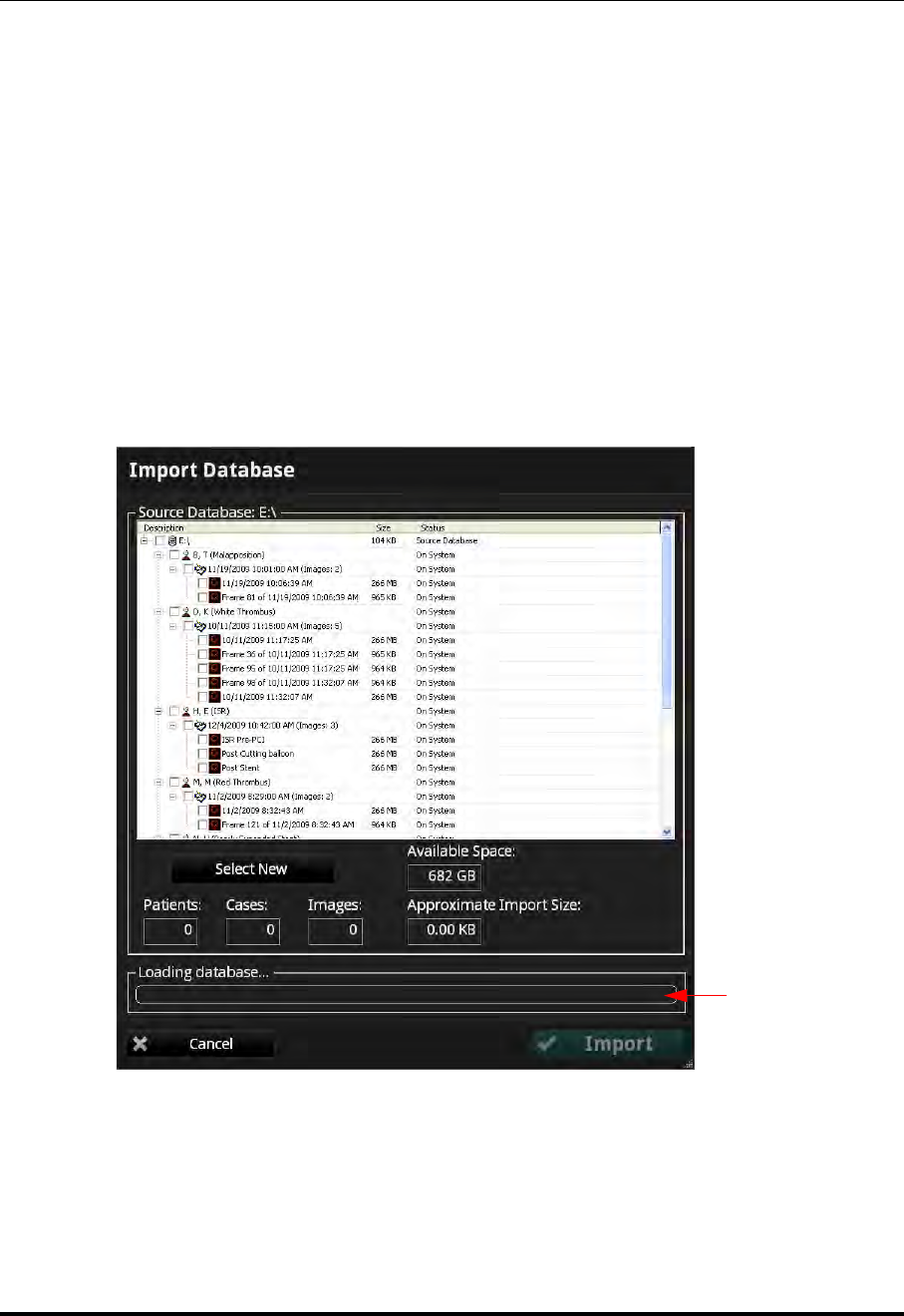
Exporting, Importing, and Managing Files
Importing Files from a CD/DVD or USB
St. Jude Medical
8-20 Part Number ARTUS100109403
Importing Files from a CD/DVD or USB
1. Connect an external database to the ILUMIEN OPTIS System:
• Insert a CD/DVD containing a database into the system.
• Connect an external hard drive to the system.
2. In the Select Patient menu, click the Import button.
The Select Database menu opens.
3. Select the database to import, and click OK.
4. The Import Database menu opens (Figure 8-7).
Figure 8-7: Import Database Menu
Progress Bar and
Message Area

Exporting, Importing, and Managing Files
Importing Files from a CD/DVD or USB
ILUMIEN OPTIS System
Instructions for Use 8-21
An import may require installation of several CD/DVDs. When a new disc is required, the
system ejects the current disc and displays a New Disc Request alert.
Table 8-3: Import Database Menu Options
Source Database List of files which will be imported. Each file is displayed in
one row, and the patient name, patient ID, image creation date
& time, comment, and status are displayed in columns. The list
is initially sorted by ascending image creation date & time and
can be sorted by any of the columns in ascending or descend-
ing order by left-clicking once or twice on the desired column
header.
As each file is imported, its Status message is updated:
•Importing - file is currently being imported.
•On System - file has been copied to the system.
•On Archive Media - file is on the current archive media
and has not yet been imported.
•Absent - file is not located on the current archive media
•Failed - attempt to import the file failed.
Select New Click to select only recordings that are not present in the ILUM-
IEN OPTIS System.
Progress Bar and Message
Area The Progress Bar indicates the status of the file transfer. The
Message Area displays information about the file and the
transfer.
Import Import the selected files.
Cancel Cancel the import.

Exporting, Importing, and Managing Files
Deleting Files
St. Jude Medical
8-22 Part Number ARTUS100109403
Deleting Files
You can delete files by any of the following methods:
• Exporting images with the Remove When Complete function turned on (see
“Exporting Files in Native (Raw) Format” on page 8-8).
• Select and delete files from the Patient Summary menu.
• Select and delete files from the Database menu.
CAUTION: Once files are deleted, they cannot be restored. After files have been
deleted, they can only be imported back to your system from your
archived copies.
Deleting Files from the Patient Summary Menu
1. In the Patient Summary menu, add a check to the checkbox of each file that you
want to delete (see Figure 8-4 on page 8-14).
A white border appears around each record that is selected.
NOTE: In the Patient Summary menu, you can select multiple files from
the same date, but not from different dates.
NOTE: To deselect a file, clear the check from the checkbox. The check and
white border disappear to indicate that the file is no longer selected.
2. Click the Delete button at the bottom of the screen.
A prompt asks you to confirm that you want to delete the selected files.
3. Click Yes to delete the files, or click No to cancel the deletion and return to the
Patient Summary menu.
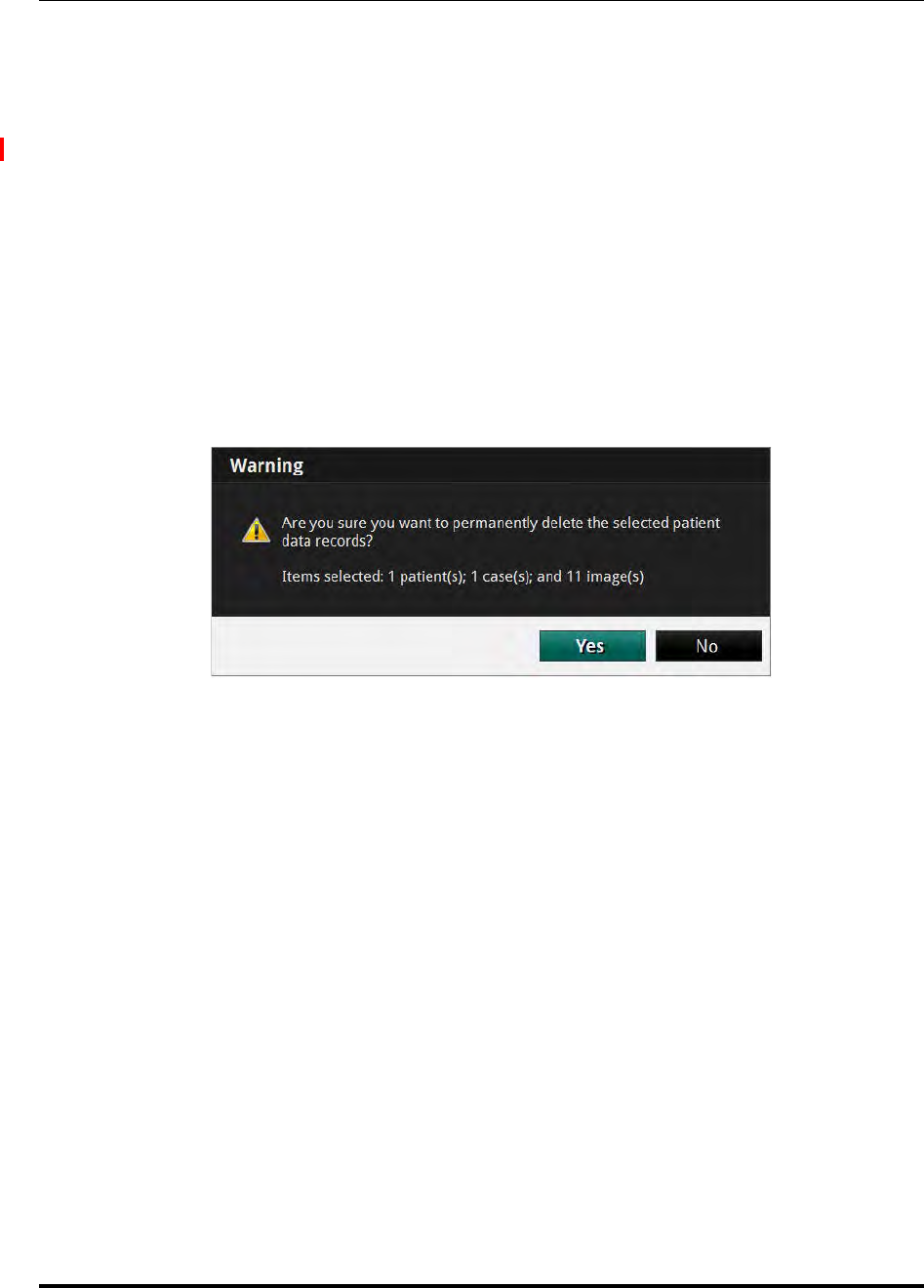
Exporting, Importing, and Managing Files
Deleting Files
ILUMIEN OPTIS System
Instructions for Use 8-23
Deleting Files from the Database Menu
1. Click the Menu button and select Setup. The Setup dialog box opens.
2. Click the Database button to open the Database menu (see Figure on page 10-7).
3. Add a check to the checkbox of any recording to be deleted.
• Add a check to the checkbox of patient to select all recordings for that patient.
• Add a check to the checkbox of the first entry in the list to select all record-
ings.
4. Click the Delete button.
A prompt asks you to confirm that you want to delete the selected files.
5. Click Yes to delete the files, or click No to cancel the deletion and return to the
Database menu.
Figure 8-8: Deletion Warning Alert

Exporting, Importing, and Managing Files
Transfer and Import Messages
St. Jude Medical
8-24 Part Number ARTUS100109403
Transfer and Import Messages
The system displays a number of different messages to inform you of problems that may
arise during transfer and import operations.
Table 8-4: Transfer Messages
Error Message Cause Action
The CD/DVD drive is empty.
Please insert a writable
CD/DVD, or click Cancel to
stop the transfer.
No CD/DVD is in the drive,
though you have attempted to
transfer files.
To continue with the export,
insert a blank CD/ DVD or a
previously used CD/DVD on
which there is sufficient space
for the transfer. To stop the
transfer, click Cancel.
None of the selected files will
fit on the disc. Please insert a
different CD/DVD, or click
Cancel to stop the transfer.
Insufficient space is available
on the destination CD/DVD
and NONE of the selected
files can be transferred to this
disc.
Insert a new writable
CD/DVD into the drive and
close the drive to transfer or
click Cancel to stop the trans-
fer and file deletion.
Some files did not fit on the
disc. Please insert another
writable CD/DVD to con-
tinue the transfer, or click
Cancel to stop the transfer.
Insufficient space is available
on the destination CD/ DVD
for all of the selected files, but
SOME of the files have been
transferred.
To continue the transfer on the
new disc, insert another writ-
able CD/DVD into the drive
and close the drive to continue
the transfer. To interrupt the
transfer, click Cancel. Some
files may be on the first disc,
some on the second. If you
select Cancel, the CD/ DVD
will contain the files previ-
ously transferred, but the
remainder will not be trans-
ferred and the uncopied files
will remain on the hard drive.
Cancelling the transfer may
damage the disc and render
previously written files
unreadable. Are you sure you
want to cancel the transfer?
You have attempted to inter-
rupt a transfer in process by
clicking Cancel.
Click No to continue the
transfer. Click Yes to stop the
transfer and risk losing the
files already transferred.
An invalid volume name was
specified. You have typed a character
that cannot be used in a vol-
ume name.
Retype the name with accept-
able characters.
Transfer failed, the destination
disk is full. The USB drive is full. Connect a different USB
drive.

Exporting, Importing, and Managing Files
Transfer and Import Messages
ILUMIEN OPTIS System
Instructions for Use 8-25
Transfer failed, the destination
disc is not blank. The CD/DVD already con-
tains files and cannot be
appended.
Insert a new writable
CD/DVD into the drive and
close the drive to transfer or
click Cancel to stop the trans-
fer.
Transfer failed, the source or
destination disk was removed. The USB drive is discon-
nected. Reconnect the USB drive.
Please insert the next CD to
continue importing the data-
base, or click Cancel to stop
importing.
The current disk is full and
has been ejected. Insert another CD/DVD in the
series or click Cancel to stop
the import.
Duplicate CD. Please insert
the next CD to continue
importing the database, or
click Cancel to stop import-
ing.
You have inserted a CD/DVD
containing files that have
already been imported.
Insert another CD/DVD in the
series. or click Cancel to stop
the import.
Database not found. Please
insert the next CD to continue
importing the database, or
click Cancel to stop import-
ing.
The currently inserted
CD/DVD does not include a
valid OCT database file.
Insert a CD/DVD which con-
tains a valid OCT database
file (OCT.mdb or OCT.dbf) or
click Cancel to stop the
import.
Incorrect database. Please
insert the next CD to continue
importing the database, or
click Cancel to stop import-
ing.
The currently inserted
CD/DVD includes a valid
OCT database file, but is not
in the same series as the previ-
ously inserted CD/DVD(s).
Insert a CD/DVD from the
same series as the last
CD/DVD or click Cancel to
stop the import.
Database import not com-
plete. You have clicked Cancel, so
the Import operation is not
complete.
Click OK to continue system
operations. Some of the files
may have been partially, but
not fully copied into the sys-
tem. If you try to open one of
these files, the system will
display an error message.
Please insert the next CD to
continue importing the data-
base, or click Cancel to stop
importing.
Additional files exists on
another disc. Insert the next disc. The mes-
sage is automatically closed
and import continues.
Table 8-4: Transfer Messages (continued)
Error Message Cause Action

Exporting, Importing, and Managing Files
Duplicate File Name Messages
St. Jude Medical
8-26 Part Number ARTUS100109403
Duplicate File Name Messages
Duplicate file name messages warn you when a file has been selected for export with the
same name as one already saved. The system does not allow any files to be overwritten.
NOTE: Do not save an image using the same name used for a previous file. St.
Jude Medical recommends that you label media containing exported files
with descriptive information, including the procedure or export date. To
resolve these errors when copying to CD/DVDs, insert another CD/DVD
into the drive and close the drive. File transfer resumes automatically. If
the transfer is cancelled, the uncopied files will remain on the hard drive.
Database Statistics
You can check the size and statistics of your system’s database using the Database Main-
tenance button in the Setup dialog box. See “Setup - Database/Maintenance Menu” on
page 10-9 for more information.
Table 8-5: Duplicate File Name Messages
Message Cause Action
Duplicate files could not be
written. Please insert a differ-
ent CD/DVD to continue the
transfer, or click Cancel to
stop the transfer
SOME of the file names in an
export set are already found
on the installed CD/DVD.
Files with non-identical
names will be written to the
current CD/DVD; files with
identical names will not be
written. To save the files with
the duplicate file names, insert
a new CD/DVD and continue
with the transfer. To stop the
transfer, click Cancel.
The disc already contains files
with the same names. Please
insert a different CD/DVD to
continue the transfer, or click
Cancel to stop the transfer.
ALL the file names in an
export set are already found
on the installed CD/DVD.
To save these files with these
file names, insert a new
CD/DVD and continue with
the transfer. To stop the trans-
fer, click Cancel. This mes-
sage may be displayed when
the Delete after transfer
checkbox in the Manage
Exported Files menu is
unchecked, leading to
re-exporting the same files.
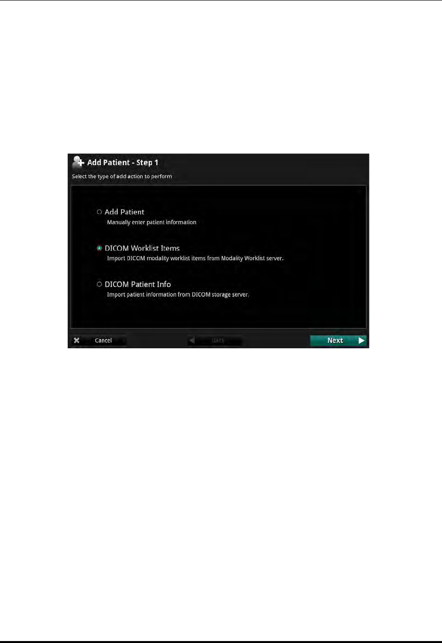
Exporting, Importing, and Managing Files
Database Statistics
ILUMIEN OPTIS System
Instructions for Use 8-27
Importing Patient Information From a DICOM Worklist or Storage Server
From DICOM Worklist
To import patient information From a DICOM Worklist, complete the following steps:
1. From the Select Patient menu, click the Add Patient button. The Add Patient -
Step 1 guidance displays.
2. Select DICOM Worklist Items. Click the Next button. The Add Patient - Step 2
guidance displays.
Figure 8-9: Add Patient - Step 1 (Worklist)
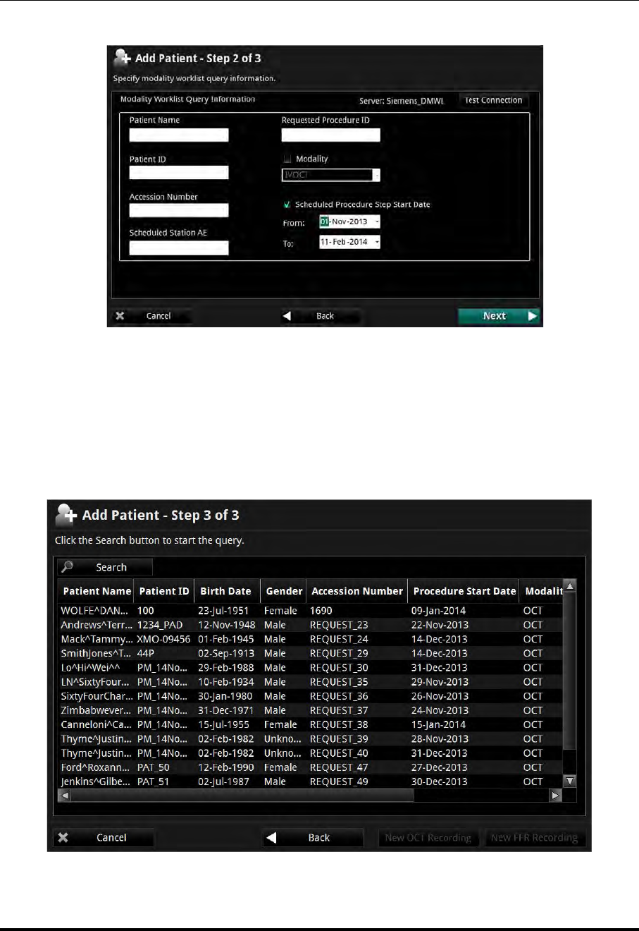
Exporting, Importing, and Managing Files
Database Statistics
St. Jude Medical
8-28 Part Number ARTUS100109403
3. Enter a valid date range to search, or un-check Scheduled Procedure Step Start
Date and enter any other valid search term. Click Next. The Add Patient - Step 3
guidance displays.
4. Select the patient by clicking on the name. The New OCT Recording button and
the New FFR Recording button become active.
Figure 8-10: Add Patient - Step 2
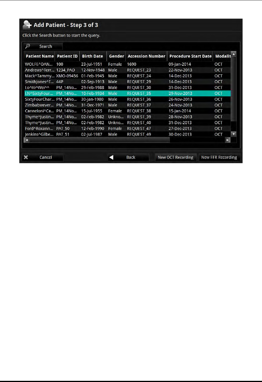
Exporting, Importing, and Managing Files
Database Statistics
ILUMIEN OPTIS System
Instructions for Use 8-29
5. Click either the New OCT Recording button or the New FFR Recording button
to continue.
From a DICOM Storage Server
To import patient information From a DICOM Storage Server, complete the following
steps:
1. From the Select Patient menu, click the Add Patient button. The Add Patient -
Step 1 guidance displays.
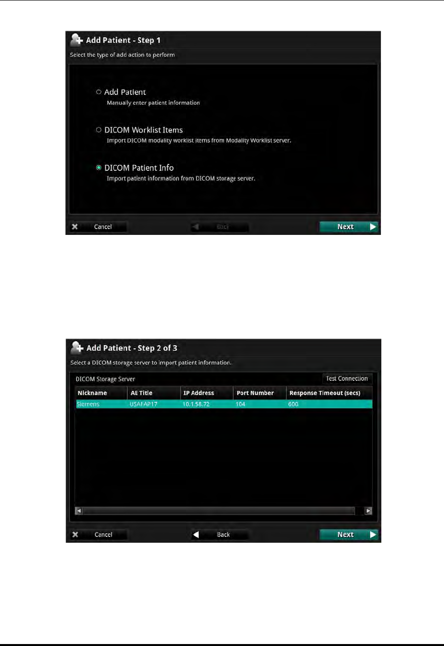
Exporting, Importing, and Managing Files
Database Statistics
St. Jude Medical
8-30 Part Number ARTUS100109403
2. Select DICOM Patient Info. Click the Next button. The Add Patient - Step 2
guidance displays.
3. If there is more than one DICOM Storage Server detected, select the desired server.
Click the Next button. The Add Patient - Step 3 guidance displays.
Figure 8-11: Add Patient - Step 1 (Storage Server)
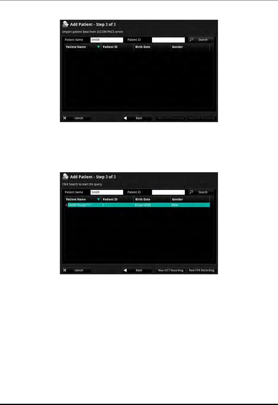
Exporting, Importing, and Managing Files
Database Statistics
ILUMIEN OPTIS System
Instructions for Use 8-31
4. Enter a search term such as the Patient Name (shown), Patient ID, or leave blank
to return the entire list of Patients. Click the Search button. The results display.
5. Click to highlight the patient, then click the New OCT Recording button or New
FFR Recording button. The patient data is entered.

Exporting, Importing, and Managing Files
Database Statistics
St. Jude Medical
8-32 Part Number ARTUS100109403

ILUMIEN OPTIS System
Instructions for Use 9-1
Cleaning & Maintenance 9
CAUTION: Only a qualified service representative can service components of the
system. Any attempt to open the system components by anyone other
than a qualified St. Jude Medical service representative will void the
warranty.
CAUTION: Do not perform cleaning or maintenance on the system in the patient
environment.

Cleaning & Maintenance
Contacting St. Jude Medical Service
St. Jude Medical
9-2 Part Number ARTUS100109403
Contacting St. Jude Medical Service
Service can be contacted at:
E-mail: OCTservice@sjm.com
Phone: +1 855 478 5833 US Toll-free
+1 651 756 5833 International
Cleaning
Cleaning of the ILUMIEN OPTIS System consists of:
• Cleaning system surfaces.
• Cleaning the DOC and its cable.

Cleaning & Maintenance
Cleaning
ILUMIEN OPTIS System
Instructions for Use 9-3
Routine Cleaning Procedure
The OPTIS Integrated DOC, DOC Holster, and Table Side Controller should be cleaned
following the facilities standard cleaning schedule, or at least every 30 days under normal
use.
1. Turn off all system components with accessible power controls and unplug the
power cables.
2. Clean system surfaces and the keyboard with a dry cloth, or a dry cloth slightly
dampened with water.
3. Clean the monitor’s LCD surface with a lint-free, non-abrasive cloth.
CAUTION: DO NOT clean the LCD surface with detergents or other clean-
ing solutions.
4. Clean exposed system cables with a soft cloth moistened with water or a mild deter-
gent.
5. Clean the DOC and the DOC optical cable with a disinfectant wipe or CidexTM1
(Glutaraldehyde 3.4%) and a soft cloth. Be particularly careful not to stress or
sharply bend the DOC optical cable.
NOTE: Though enclosed in a bag during use, the DOC is the system compo-
nent most exposed to dirt, fluids, and debris.
NOTE: The Table Side Controller is not water-proof. Be careful to not use
excessive moisture when cleaning this device.
6. Clean all other exposed system cables with a soft cloth moistened with water or
water and a mild detergent.
1. Cidex is a trademark of Johnson & Johnson Corporation.

Cleaning & Maintenance
Maintenance
St. Jude Medical
9-4 Part Number ARTUS100109403
Maintenance
Maintenance of the system consists of:
• Cleaning the optical connection in the DOC and the Dragonfly™ Imaging Catheter.
• Replacing the optical adapter in the DOC.
• Inspecting exposed cable connections.
• Transferring log files.
• Identifying the installed software version.

Cleaning & Maintenance
Maintenance
ILUMIEN OPTIS System
Instructions for Use 9-5
Optical Connection Cleaning Procedure
The optical connection between the DOC and the Dragonfly™ Imaging Catheter should
be cleaned whenever there is a loss of image quality. Image quality should also be
checked every 3 months, and the connection cleaned if there is a loss of quality.
CAUTION: This procedure should not be performed during a patient case on a
sterile catheter.
NOTE: Before beginning this procedure ensure that you have the St. Jude Medical
Optical Fiber Connector Cleaner available.
NOTE: Do not touch any of the optical connectors or the end of the Optical Fiber
Connector Cleaner as this may damage them.
1. If a catheter is connected to the DOC, press the Unload button on the DOC and wait
until the “lock” LED stops flashing. Once the “lock” LED is off, remove the cathe-
ter.
2. Click the Menu button and select the Setup option. The Setup dialog box displays.
3. Click the Service button. The Service menu displays.
4. In the DOC Service section of the Service menu, click the Enter button.
The DOC optical carriage moves all the way to the front and then locks into posi-
tion for 1 minute. Rotation of the DOC rotary motor is stopped and the laser source
is turned off.
5. Remove the sizing cap from the end of the Optical Fiber Connector Cleaner (see
Figure 9-1).
6. Insert the cleaner into the center of the Optical Adapter in the DOC, ensuring it
seats fully, and press until it clicks.
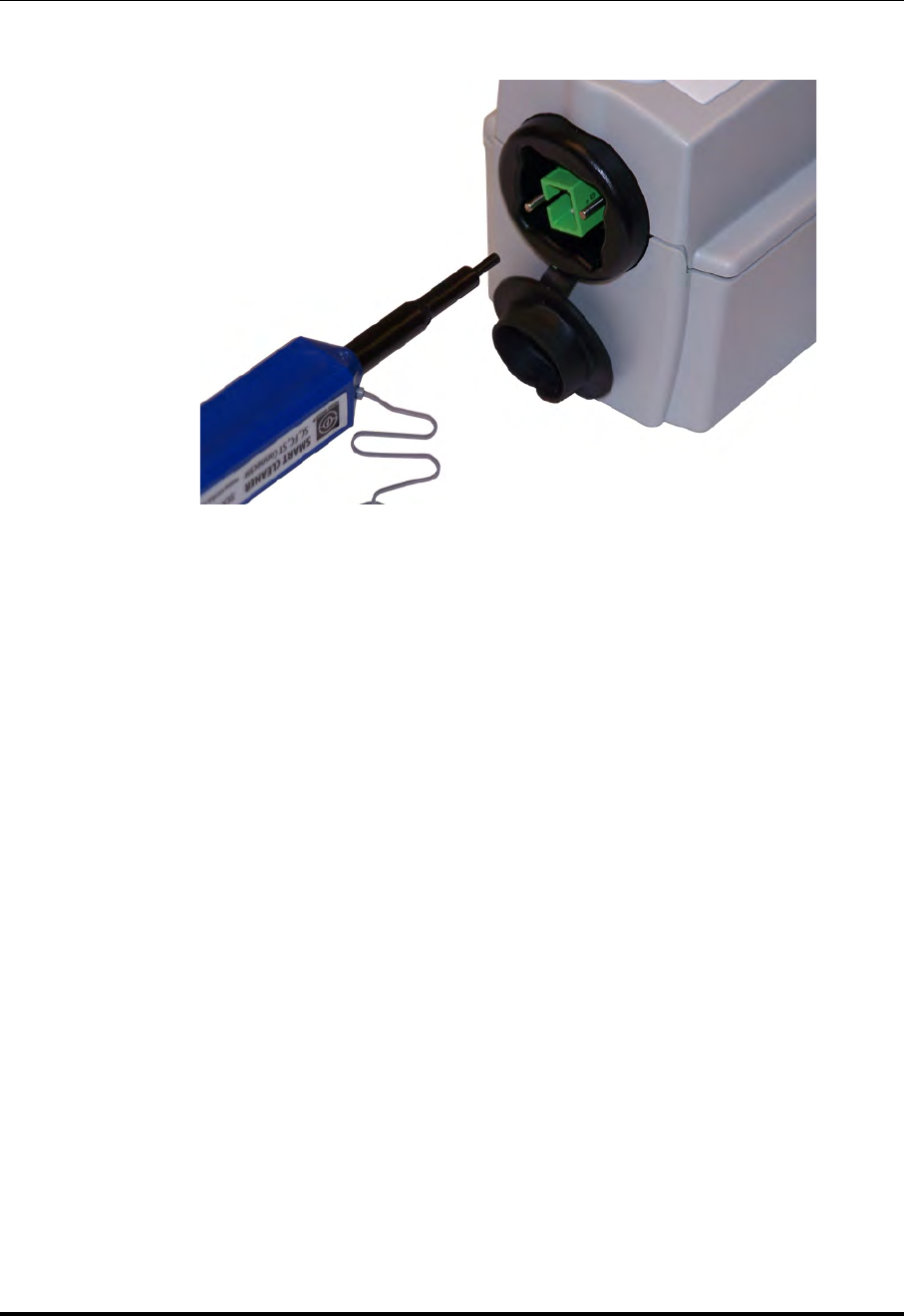
Cleaning & Maintenance
Maintenance
St. Jude Medical
9-6 Part Number ARTUS100109403
The cleaning material in the Optical Fiber Connector Cleaner is moved over the
optical connection cleaning it.
7. Remove the cleaner from the DOC.
8. In the DOC Service section of the Service menu, click the Exit button.
The DOC optical carriage moves all the way to the back and all DOC functions are
returned to their normal state.
9. Click on OK or Cancel to close the Setup dialog box.
10. Open the sizing cap and place it on the end of the Optical Fiber Connector Cleaner
(see Figure 9-2).
11. Insert the cleaner into the optical connection in the Dragonfly Imaging Catheter,
ensuring it seats fully, and press until it clicks.
The cleaning material in the Optical Fiber Connector Cleaner is moved over the
optical connection cleaning it.
Figure 9-1: Inserting Cleaner Into Optical Adapter
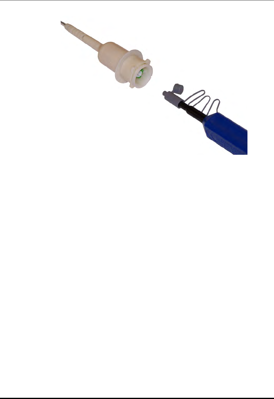
Cleaning & Maintenance
Maintenance
ILUMIEN OPTIS System
Instructions for Use 9-7
12. Remove the cleaner from the Dragonfly.
13. Reconnect the Dragonfly Imaging Catheter to the DOC.
14. Return the system to normal operation.
Figure 9-2: Inserting Cleaner Into Catheter
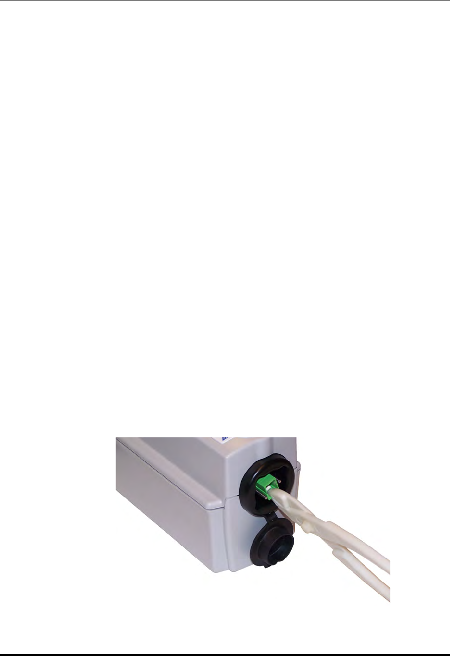
Cleaning & Maintenance
Maintenance
St. Jude Medical
9-8 Part Number ARTUS100109403
Optical Adapter Replacement Procedure
The Optical Adapter should be replaced every 200 cycles or 1 year (which ever comes
first), or if cleaning (see “Optical Connection Cleaning Procedure”) does not improve the
image quality.
CAUTION: This procedure should not be performed during a patient case.
NOTE: Before beginning this procedure ensure that you have a replacement St.
Jude Medical Optical Adapter and pliers supplied with it available.
NOTE: Do not touch any of the optical connectors as this may damage them.
1. If a catheter is connected to the DOC, press the Unload button on the DOC and wait
until the “lock” LED stops flashing. Once the “lock” LED is off, remove the cathe-
ter.
2. Click the Menu button and select the Setup option. The Setup dialog box displays.
3. Click the Service button. The Service menu displays.
4. In the DOC Service section of the Service menu, click the Enter button.
5. Click on the Enter DOC Service button.
The DOC optical carriage moves all the way to the front and then locks into posi-
tion for 1 minute. Rotation of the DOC rotary motor is stopped and the laser source
is turned off.
6. Use pliers to grip either short surface of the adapter as shown (see Figure 9-3).
Ensure the pliers seat over the lip on the end of the adapter.
Figure 9-3: Proper Gripping of Adapter for Removal
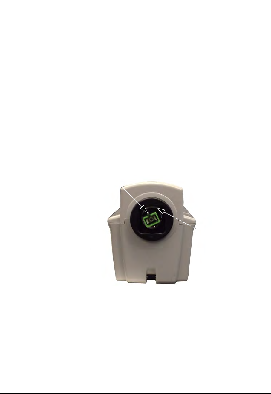
Cleaning & Maintenance
Maintenance
ILUMIEN OPTIS System
Instructions for Use 9-9
7. Pull the adapter straight out of the DOC.
NOTE: Ensure that the adapter does not rotate while it is being removed as
this could damage the DOC or break the adapter.
8. Remove the cap and plug from the replacement Optical Adapter.
NOTE: Do not touch any of the optical connectors as this may damage them.
9. Using your fingers, align the new adapter with the DOC, ensuring the key is aligned
with the slot in the optical carriage, and firmly press it into place.
There is a small click when the adapter seats.
NOTE: If the carriage moves when you press on the adapter, click the Exit
button in the DOC Service section of the Service menu. Once it
changes to Enter, click it again. Once the optical carriage is locked
into position at the front of the DOC firmly press the adapter into
place.
10. In the DOC Service section of the Service menu, click the Exit button.
The DOC optical carriage moves all the way to the back and restores all DOC func-
tions to their normal state.
11. Click on OK or Cancel to close the Setup dialog box.
12. Return the system to normal operation.
Figure 9-4: Alignment of Optical Adapter with Optical Carriage
Optical Carriage
Key Slot

Cleaning & Maintenance
Maintenance
St. Jude Medical
9-10 Part Number ARTUS100109403
Cable Connection Inspection Procedure
1. Make sure the power cords are in good condition and are properly plugged in.
2. If a secondary ground connection is being used, ensure that both ends of the cable
are secure.
3. Ensure all other connectors are fully seated and properly secured.
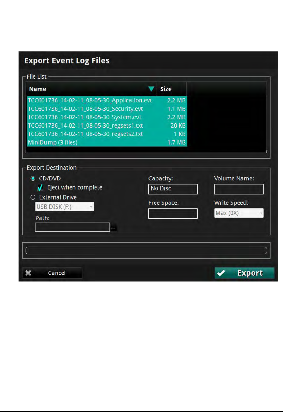
Cleaning & Maintenance
Maintenance
ILUMIEN OPTIS System
Instructions for Use 9-11
Transferring Log Files
Log files may be transferred to a CD or external USB device so that you can archive them
or E-mail them to St. Jude Medical Service.
NOTE: When there are multiple repeated events of the same type the event logs
are condensed into two messages. The first message logs the initial event,
and the second message logs the event along with a repeat count.
1. Click the Menu button and select the Setup option. The Setup dialog box displays.
2. Click the Service button. The Service menu displays.
3. In the Service Log area, click the Export button.
Figure 9-5: Transfer Event Log Files Menu

Cleaning & Maintenance
Maintenance
St. Jude Medical
9-12 Part Number ARTUS100109403
The Transfer Event Log Files menu opens (Figure 9-5), which lists all the files to
be exported.
4. Click to select a Transfer Destination:
NOTE: If an output device is not available, that option cannot be selected.
NOTE: Check that the Free space in the Drive Capacity section is large
enough to save the files that are being exported.
•Click CD/DVD to export to a CD/DVD.
If the inserted CD/DVD is blank, you can edit the name in the Volume Label
field.
•Click External Drive to export to an external USB device.
If necessary, click the External Drive selection box to select the correct drive
location from the drop-down menu.
Click the Ellipsis (...) button to the right of the Path selection box to browse
for a specific folder on the device.
5. Click the Transfer button to transfer the files or Cancel to cancel the operation.
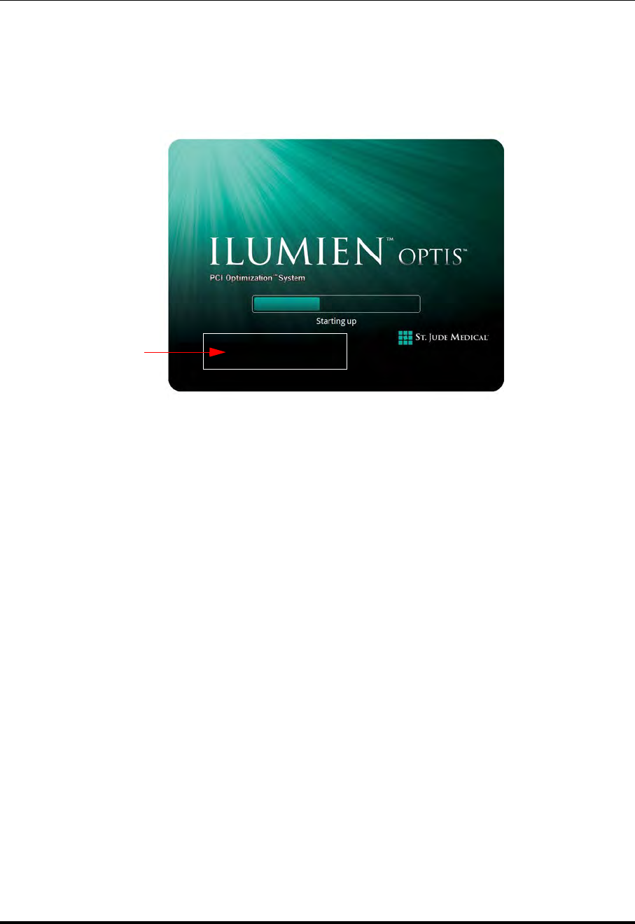
Cleaning & Maintenance
Infection Control
ILUMIEN OPTIS System
Instructions for Use 9-13
Identifying the Software Version
The Startup window (Figure 9-6) shows the version and copyright information for the
system. If the system is running, type <Ctrl-S> to open the Startup window. The software
version information might be required when contacting St. Jude Medical Service.
Infection Control
Follow the infection control procedures established in your institution for protection of
both staff and patient.
Blood on system components, panels, and cables should be removed by using a gauze pad
with soap and water, and drying with a soft cloth to prevent corrosion. The DOC cable can
be cleaned with a disinfectant wipe or Cidex and a soft cloth.
Figure 9-6: System Startup Window
Software
version and
copyright
information

Cleaning & Maintenance
User Troubleshooting
St. Jude Medical
9-14 Part Number ARTUS100109403
User Troubleshooting
Table 9-1 provides basic guidelines for troubleshooting the ILUMIEN OPTIS System.
“Troubleshooting OCT Acquisition” on page 5-19 explains what to do if a catheter fails
during pullback.
If your problem is not resolved after attempting the suggested remedies, contact your ser-
vice representative or E-mail OCTservice@sjm.com.
Table 9-1: User Troubleshooting Tips
Symptom Possible Causes Remedy
General
Screen blank, power
indicator on moni-
tor not lit.
Display not turned on. Press the power button on the monitor to
turn on monitor power.
Display power cord
unplugged. Plug the monitor power cord into the back
of monitor.
System power not
turned on. Turn on the system power with the main
power switch, located next to the power
cord connection.
System power cord not
plugged in or not tight
at either system end or
wall connection.
Check to make sure plug is tightly con-
nected to both the system and to the wall
outlet.
Main system power
fuse is blown. Refer to the Electrical label on the system
(located next to the power cord connection)
for fuse information. Contact your service
representative for instructions.
Outlet power disrupted. Check voltage at the wall outlet.
Screen blank, power
indicator on moni-
tor lit.
PC auto-boot failed. Turn off the main power switch and wait
fifteen seconds. Turn the main power
switch back on, and press the On/Standby
button on the right side of the keyboard to
start the system. If the system still does not
start, contact your St. Jude Medical service
representative for instructions.
Monitor not enabled. Click <Alt+C> on the keyboard to enable
the display. If the screen remains blank,
turn off the main power switch and wait fif-
teen seconds. Turn the main power switch
back on, and press the On/Standby button
on the right side of the keyboard to start the
system.

Cleaning & Maintenance
User Troubleshooting
ILUMIEN OPTIS System
Instructions for Use 9-15
Connections
During data export,
the system does not
list the USB drive
plugged into the
USB port.
The connected USB
drive is not compatible
with the system, or the
USB drive requires for-
matting.
Connect only a USB Drive supported by
Windows 7 SP1. Refer to the instructions
for use that came with your USB drive to
determine if formatting is required.
Screen message
“Imaging engine ini-
tialization failed” is
displayed at startup.
This message can be
caused by several prob-
lems, including loose or
damaged system con-
nections.
Shut down the system, turn off the main
system power, and wait 15 seconds. Then
turn the system back on. If the error is dis-
played again, note the error code displayed
(if any) then contact your St. Jude Medical
service representative for instructions.
DOC
Optical fiber does
not rotate when Live
View is pressed.
The Stop button on the
DOC was pressed. Check screen for message and follow
instructions.
Imaging catheter defec-
tive, optical fiber does
not rotate.
Replace imaging catheter.
DOC makes exces-
sive noise without
imaging catheter
connected.
DOC mechanism fail-
ure. Contact your service representative to
obtain a replacement DOC.
Imaging
OCT image dim,
with no background
noise visible.
Monitor contrast and
brightness set incor-
rectly.
Set monitor contrast and brightness using
monitor controls on the monitor.
Image contrast levels
set incorrectly. Check the Presentation Settings on the
Settings tab of the OCT Settings menu
(normal settings are: Black level = 5%,
White level = 90%. With the optical fiber
rotating (scanning mode), reduce the Black
level until background noise just becomes
visible. Lack of background noise during
optical fiber rotation indicates a defective
imaging engine. See other possible causes
and remedies below.
Defective imaging cath-
eter causing system sat-
uration.
Remove imaging catheter from DOC. If
background noise appears, the imaging
catheter is defective. Replace catheter.
Table 9-1: User Troubleshooting Tips (continued)
Symptom Possible Causes Remedy

Cleaning & Maintenance
User Troubleshooting
St. Jude Medical
9-16 Part Number ARTUS100109403
Dirty connection
between DOC and
imaging catheter.
Refer to “Optical Connection Cleaning
Procedure” on page 9-5 to clean the con-
nection.
Table 9-1: User Troubleshooting Tips (continued)
Symptom Possible Causes Remedy

Cleaning & Maintenance
System Disposal
ILUMIEN OPTIS System
Instructions for Use 9-17
System Disposal
Disposal of the equipment must be in accordance with local laws.

Cleaning & Maintenance
System Disposal
St. Jude Medical
9-18 Part Number ARTUS100109403

ILUMIEN OPTIS System
Instructions for Use 10-1
User Interface Reference 10
Setup Dialog Box and Submenus
The Setup dialog box provides access to all of the configuration and service functions for
the system. The Setup dialog box is accessed by selecting the Setup option from the
Menu button options on the Select Patient or Patient Summary screen.
NOTE: When creating or reviewing an OCT recording, the Settings button opens
a context-sensitive OCT Settings menu. When creating an FFR recording,
the Settings button opens the FFR Settings menu.
All menus within the Setup dialog box share the following common buttons located at the
bottom of the dialog box.
Table 10-1: Setup Dialog Box Common Options
Refresh Click to update the values displayed in the current tab.
OK Click to approve any changes and close the Setup dialog box.
Cancel Click to cancel any changes and close the Setup dialog box.
Apply Click to approve any changes and keep the Setup dialog box open.
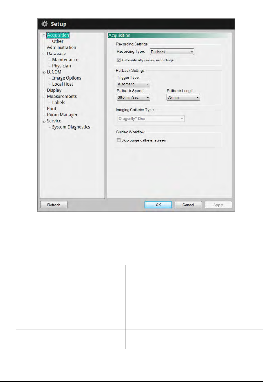
User Interface Reference
Setup - Acquisition Menu
St. Jude Medical
10-2 Part Number ARTUS100109403
Setup - Acquisition Menu
Table 10-2: Setup - Acquisition Menu Settings
Recording Type
Sets the recording type for image acquisition:
Pullback - Performs a recording while the imaging
core of the catheter is pulled back within the cathe-
ter sheath.
Stationary - The system records the live view
image for 6 seconds without pulling the imaging
core of the catheter back.
Automatically review recordings Turns on and off automatic review after recording
real-time images.
Figure 10-1: Setup - Acquisition Menu

User Interface Reference
Setup - Acquisition Menu
ILUMIEN OPTIS System
Instructions for Use 10-3
Trigger Type
Sets the Pullback trigger type to use for image
acquisition:
Automatic - The system automatically begins a
recording when it detects that the vessel has been
cleared by the flush injection.
Manual - The System does not perform a pullback
until you click the Start Pullback button on the
screen, or press the Enable button on the DOC.
Pullback Speed
Sets the pullback speed.
NOTE: When connected to an original C7 Drag-
onfly imaging catheter, the Pullback
Speed settings are limited to 10.0
mm/sec, 20.0 mm/sec, and 25.0 mm/sec.
For Dragonfly Duo or OPTIS, available
speeds are 18 and 36 mm/sec.
Pullback Length
Sets the length of the pullback.
NOTE: When connected to an original C7 Drag-
onfly imaging catheter, the Pullback
Length setting is limited to 54 mm. For
Dragonfly Duo or OPTIS Pullback
Length is 54 mm when speed is 18
mm/sec and 75 mm when speed is 36
mm/sec.
Imaging Catheter Type
NOTE: This displays the type of catheter when a
catheter has been connected.
NOTE: Only Dragonfly imaging catheters are
approved for use with the ILUMIEN OPTIS
System for cardiovascular imaging.
Guided Workflow Turns on and off the appearance of the purge cathe-
ter guidance message.
Table 10-2: Setup - Acquisition Menu Settings (continued)
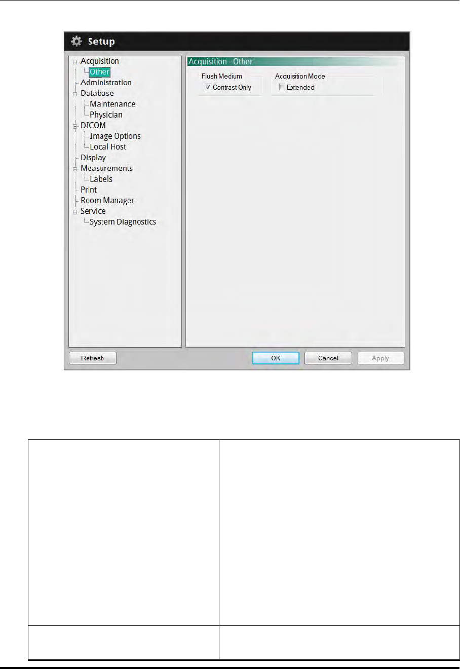
User Interface Reference
Setup - Acquisition/Other Menu
St. Jude Medical
10-4 Part Number ARTUS100109403
Setup - Acquisition/Other Menu
Table 10-3: Setup - Acquisition/Other Menu Settings
Flush Medium
Controls the contrast options available in the Flush
Medium drop-down box.
Checked - Only 100% contrast is available, and
the Flush Medium drop-down box under Settings
is unavailable.
Unchecked - All configured contrast options are
available for selection in the Flush Medium
drop-down box.
NOTE: To change the Flush Medium setting
before performing an OCT recording, see
“Confirm Recording Settings” on page
5-12.
Acquisition Mode This option should remain unchecked unless
instructed otherwise by SJM personnel.
Figure 10-2: Setup - Acquisition/Other Menu
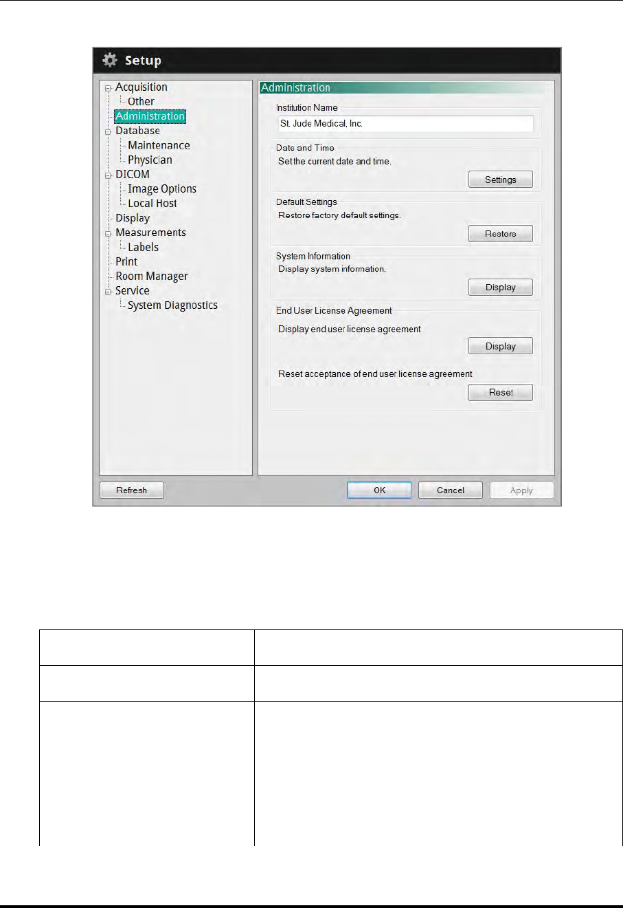
User Interface Reference
Setup - Administration Menu
ILUMIEN OPTIS System
Instructions for Use 10-5
Setup - Administration Menu
Table 10-4: Setup - Administration Menu Settings
Institution Name Click here and enter or clear the institution name.
Date and Time Opens the system Date and Time Properties menu.
Default Settings
Resets all user-entered configuration values except the
date and time to the original factory default values.
CAUTION: Restoring factory default settings resets
ALL user-entered configuration values
except the date and time. This button
should be used only by qualified service
personnel or under their direction.
Figure 10-3: Setup - Administration Menu

User Interface Reference
Setup - Administration Menu
St. Jude Medical
10-6 Part Number ARTUS100109403
System Information Displays current date, system name, institution name, and
software version
End User License
Agreement
Displays EULA.
Resets EULA. The EULA must be accepted upon first
operation after reset in order to access the system.
Table 10-4: Setup - Administration Menu Settings (continued)
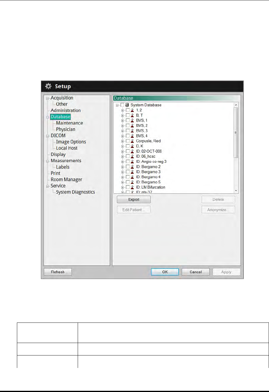
User Interface Reference
Setup - Database Menu
ILUMIEN OPTIS System
Instructions for Use 10-7
Setup - Database Menu
The Database menu in the Setup dialog box shows a list of all files in the database. From
this menu, you can select patients or individual recordings for export, delete recordings,
or select a patient for editing.
Click on individual recordings to select them, or click on a patient’s name to select all recordings
for that patient, or click on the database to select all recordings.
Table 10-5: Setup - Database Menu Settings
Database display The database display shows all recordings, grouped by patient name,
and then by the date of the recordings.
Export Exports the selected recordings.
Delete Deletes the selected recordings.
Figure 10-4: Setup - Database Menu

User Interface Reference
Setup - Database Menu
St. Jude Medical
10-8 Part Number ARTUS100109403
Edit Patient... Click on a patient’s name to edit the patient’s information. See “Edit-
ing Patient Information” on page 3-8 for more information.
Anonymize... Click on a patient’s name to remove the patient’s identifying informa-
tion from the record. See “Exporting Files in Native (Raw) Format”,
Step 3, on page 8-8, for an explanation of the anonymization function.
Table 10-5: Setup - Database Menu Settings (continued)
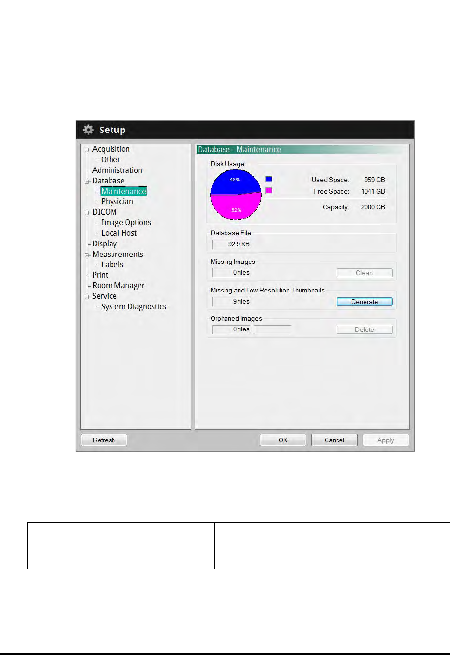
User Interface Reference
Setup - Database/Maintenance Menu
ILUMIEN OPTIS System
Instructions for Use 10-9
Setup - Database/Maintenance Menu
You can check the status of the system’s OCT database using the Database Maintenance
menu in the Setup dialog box. From this menu, you can check the size of the database
file, as well as the number of files referenced by the database and the combined size of
these files. This menu also warns you of possible issues found with files in the system’s
database.
Table 10-6: Setup - Database/Maintenance Menu Settings
Disk Usage Provides both a graphic and text showing the
amount of free and used space on the system’s hard
disk.
Figure 10-5: Setup - Database/Maintenance Menu

User Interface Reference
Setup - Database/Maintenance Menu
St. Jude Medical
10-10 Part Number ARTUS100109403
Database File Indicates the size of the database file.
Missing Images
OCT image files that are referenced by the data-
base but could not be found. Click the Clean but-
ton to remove references to files that cannot be
found.
Missing and Low Resolution
Thumbnails
Thumbnail image files that are missing or are low
resolution. Click the Generate button to generate
new thumbnail image files.
Orphaned Images
OCT image files that were found on the system but
are not referenced by the database. Click the Delete
button to delete these orphaned files to free up
additional hard disk space.
Table 10-6: Setup - Database/Maintenance Menu Settings (continued)
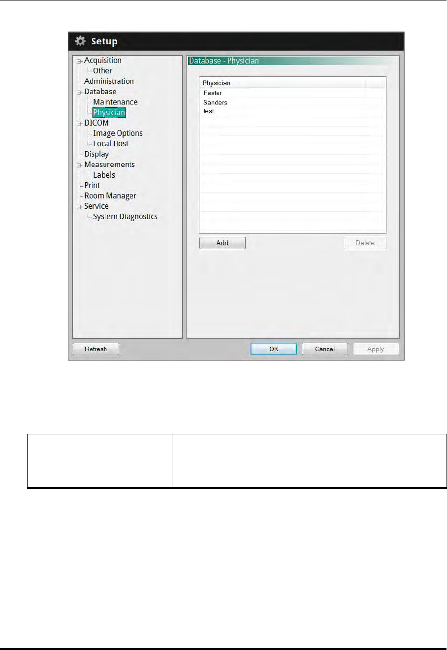
User Interface Reference
Setup - Database/Physician Menu
ILUMIEN OPTIS System
Instructions for Use 10-11
Setup - Database/Physician Menu
Table 10-7: Setup - Database/Physician Settings
Physician list Shows a list of all physician names entered in the system.
• Click Add to add a new physician name.
• Click a name and click Delete to remove the name.
Figure 10-6: Setup - Database/Physician Menu

User Interface Reference
Setup - DICOM Menu
St. Jude Medical
10-12 Part Number ARTUS100109403
Setup - DICOM Menu
The DICOM menus in the Setup dialog box are used to configure the network settings of
the system and the Remote DICOM Server so that the system can initiate a network con-
nection between the two systems. If multiple network adapters exist on the system (not a
St. Jude Medical standard configuration) only the primary network adapter can be used.
CAUTION: The ILUMIEN OPTIS System should only be connected to a secure
intranet. Direct connection to the Internet may interfere with correct
operation and/or result in inappropriate access to patient information,
and voids system warranties.
Please note St. Jude Medical makes no representation or warranty
that use of the ILUMIEN OPTIS System complies with applicable pri-
vacy, security and confidentiality laws, but encourages you to assess
your own risk as you use, disclose, control, process or transfer patient
health information with the system.
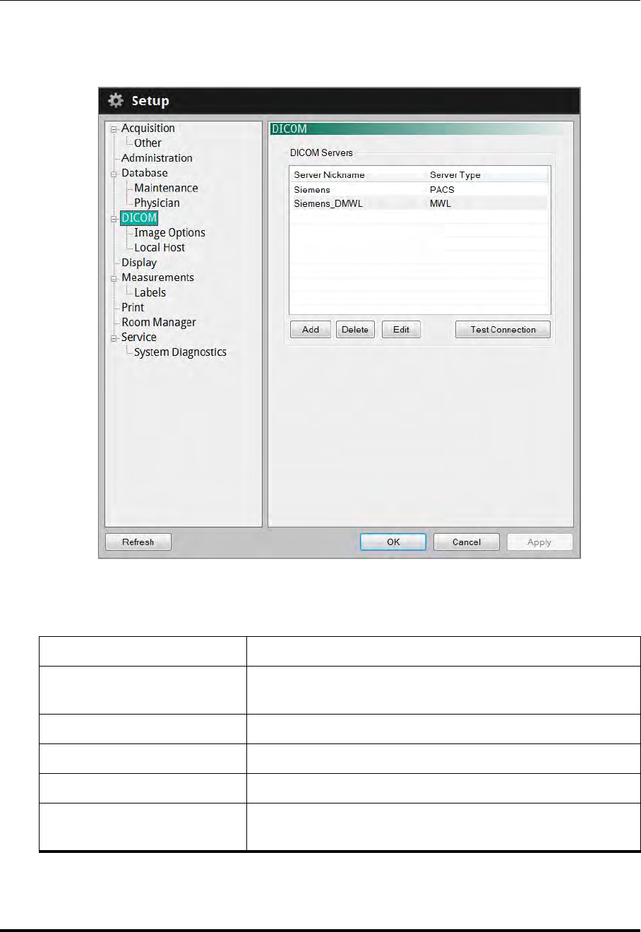
User Interface Reference
Setup - DICOM Menu
ILUMIEN OPTIS System
Instructions for Use 10-13
It is strongly recommended you contact your IT department to set up the system on the
DICOM server. Refer to the St. Jude Medical DICOM Conformance Statement for more
information on configuration.
Table 10-8: Setup - DICOM Menu Settings
Server Nickname Displays the Nickname for the server.
Server Type Displays the type of DICOM server; either PACS or Modal-
ity Worklist (MWL)
Add Click to Add a server.
Delete Click to Delete a server.
Edit Click Edit to display the Configure DICOM menu.
Test Connection Click to send a Test signal to the server and confirm that
you have successful communication.
Figure 10-7: Setup - DICOM Menu
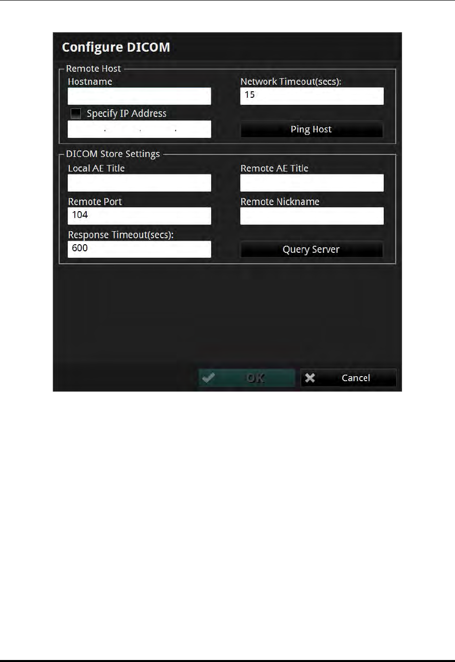
User Interface Reference
Setup - DICOM Menu
St. Jude Medical
10-14 Part Number ARTUS100109403
Figure 10-8: Configure DICOM Menu

User Interface Reference
Setup - DICOM Menu
ILUMIEN OPTIS System
Instructions for Use 10-15
Table 10-9: Setup - Configure DICOM Menu Settings
Hostname The host name of the network server that contains the
Remote DICOM Server. Use this option to identify the
server if the network supports the Domain Name System
(DNS) and the host name is known; otherwise, use Specify
IP Address (see below).
Network Timeout (secs) The maximum time to allow for a network ping response
from the network server that contains the Remote DICOM
Server. The minimum setting is 1 second while the maxi-
mum is 120 seconds. The default is 15 seconds.
Specify IP Address The IP address of the network server that contains the
Remote DICOM server. If the Remote Hostname is used to
identify the server, this field will be automatically filled in if
the Ping Host button (Figure 10-8) is successfully used to
verify the network connection. Check the Specify checkbox
to the right of this option to explicitly specify the remote IP
address.
Ping Host This button can be used to test the network connection
between the System and the Remote DICOM Server Host. If
Hostname or IP address is not correct, a Ping Failed error
message displays.
Local AE Title The AE (Application Entity) title used to identify the Local
DICOM Store SCU (Service Class User) used by the ILUM-
IEN OPTIS System.
Remote AE Title The AE title used to identify the Remote DICOM Server
SCP (Service Class Provider) to which the system connects.
Remote Port The port number on which the Remote DICOM Server Host
will be listening for connection requests. The default is 104.
Remote Nickname The nickname of the remove server defined by the user (16
characters maximum).
Query Server Click to send a request from the system to the remote server
to query the presentation context supported by the remote
server. A test connection request is also sent from the server
along with the query.

User Interface Reference
Setup - DICOM Menu
St. Jude Medical
10-16 Part Number ARTUS100109403
Response Timeout (secs) The maximum time to allow for a response from the Remote
DICOM Server after sending a DICOM request. The mini-
mum setting is 15 seconds while the maximum is 1800. The
default is 600 seconds.
Press the Test Connection button to test the connection
between the Local DICOM Store SCU and the Remote
DICOM Server SCP. For a successful test:
• A TCP/IP connection is successfully made from the sys-
tem to the remote server using the server IP address and
port.
• A DICOM Associate Connection between the Local SCU
and the Remote SCP is accepted by the SCP.
• A C-Echo request (Verification class) from the Local
SCU results in a successful response from the Remote
SCP.
NOTE: If the DICOM server does not support Multi-Frame
True Color Secondary Capture, a warning message
appears, telling you to use SC-Image-Storage SOP
class instead. If the DICOM server supports neither
the Multi-Frame True Color Secondary Capture nor
Secondary Capture, a warning message appears:
"The presentation syntax supported by the remote
server is not compatible. Images cannot be
exported to the remote DICOM server."
NOTE: The Test Connection button is unavailable if the
Obtain an IP Address Automatically checkbox is
checked. See “Setup - DICOM/Local Host Menu”
on page 10-19.
Table 10-9: Setup - Configure DICOM Menu Settings (continued)
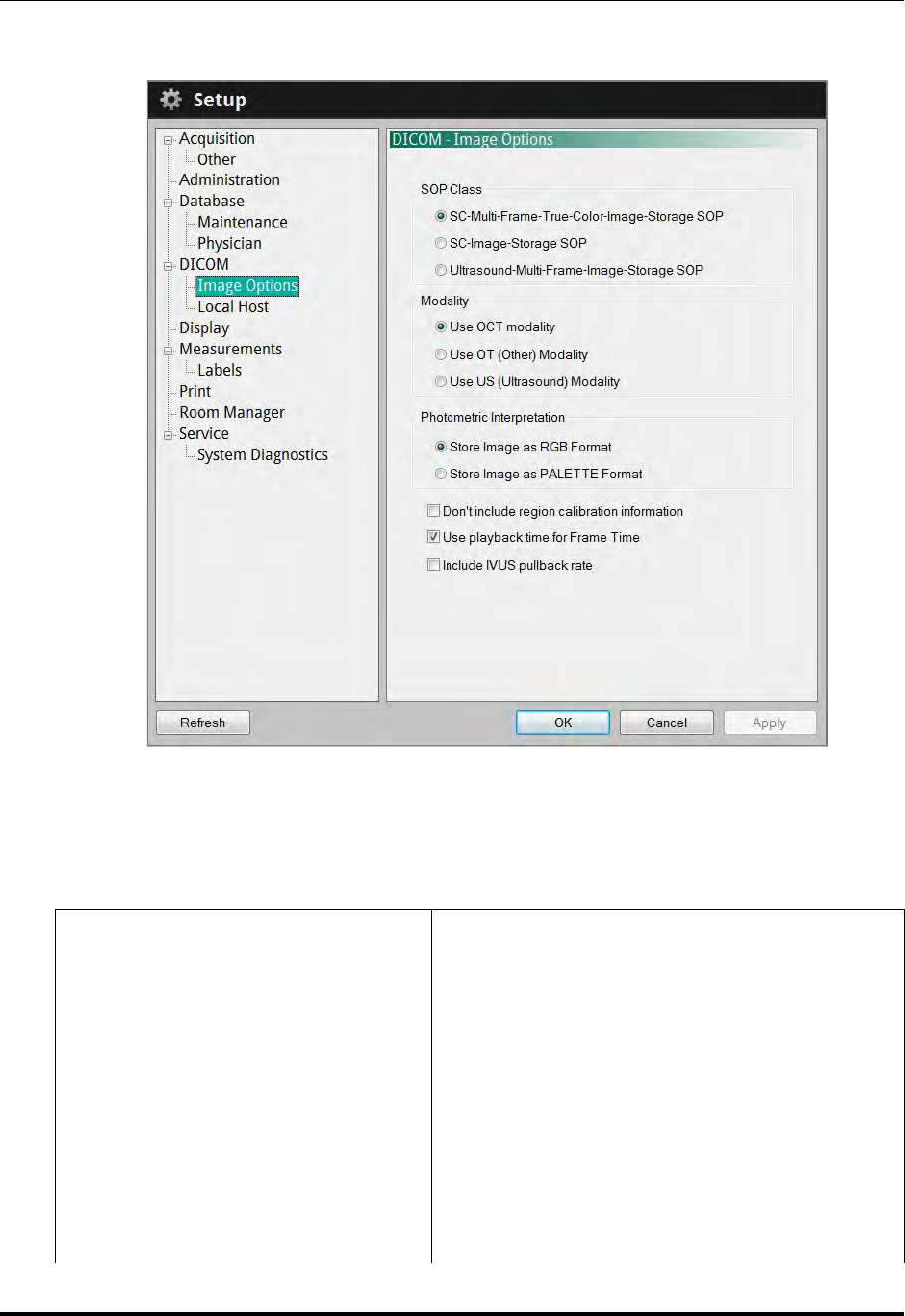
User Interface Reference
Setup - DICOM/Image Options Menu
ILUMIEN OPTIS System
Instructions for Use 10-17
Setup - DICOM/Image Options Menu
Table 10-10: Setup - DICOM/Image Options Menu Settings
SOP Class
SC-Multi-Frame-True- Color-Image-Storage
SOP: When this button is selected, DICOM
images are exported as Multi-Frame True Color
Secondary Capture. This selection is checked by
default.
SC-Image-Storage SOP: When this button is
selected, DICOM images are exported as Sin-
gle-Frame Secondary Capture.
Ultrasound-Multi-Frame-Image-Storage SOP:
When this button is selected, the images are
exported as Ultrasound Multi-Frame DICOM data
sets.
Figure 10-9: Setup - DICOM/Image Options Menu

User Interface Reference
Setup - DICOM/Image Options Menu
St. Jude Medical
10-18 Part Number ARTUS100109403
Modality Check to select the image modality: OCT, OT
(Other), or US (Ultrasound). The default DICOM
export modality is OCT.
Photometric Interpretation Check to select the export format for DICOM
images: RGB or PALETTE. The default format is
RGB. PALETTE yields smaller file sizes.
Don’t include region calibration
information
If this box is checked, region calibration informa-
tion is not included in the DICOM data.
Table 10-10: Setup - DICOM/Image Options Menu Settings (continued)
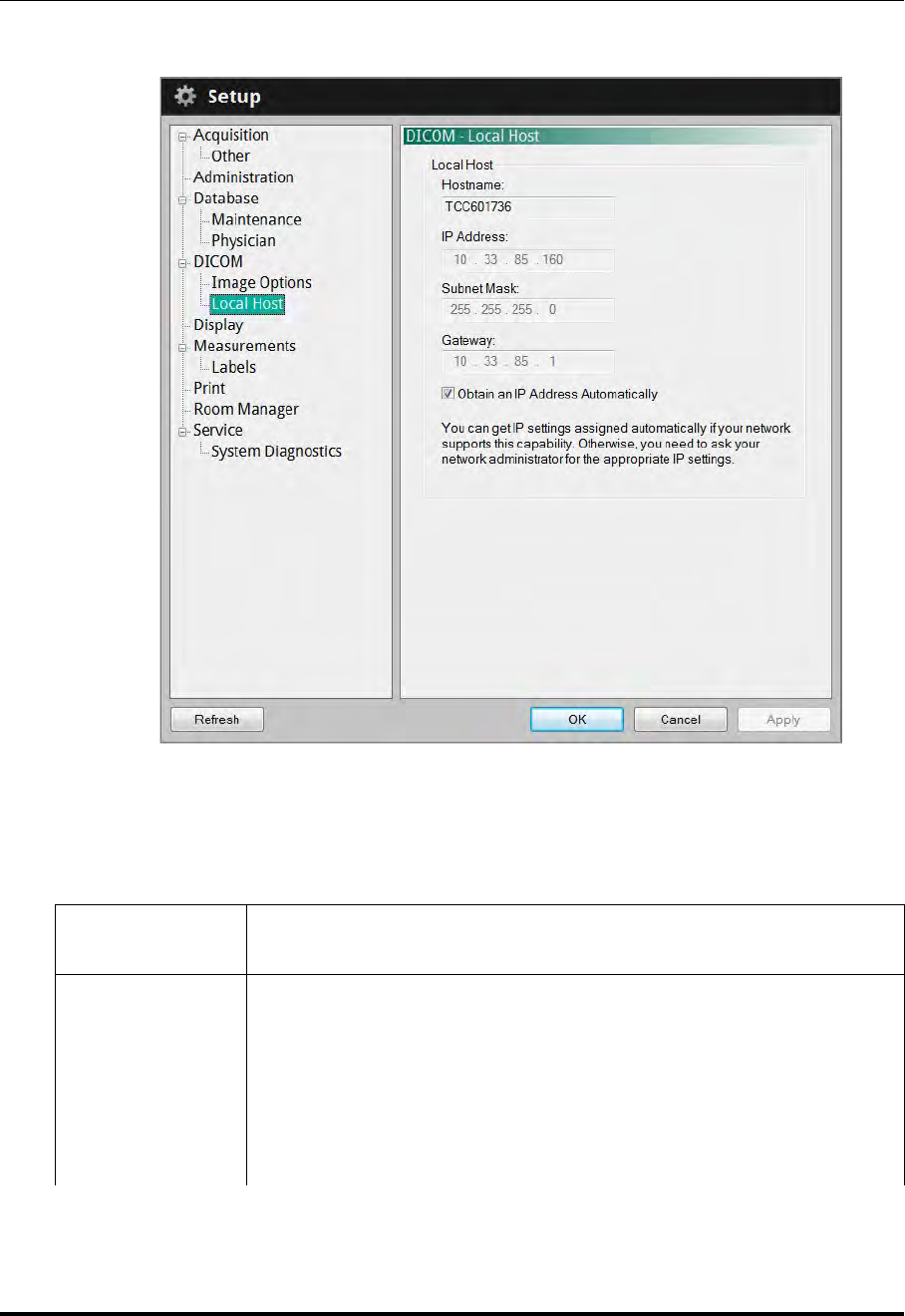
User Interface Reference
Setup - DICOM/Local Host Menu
ILUMIEN OPTIS System
Instructions for Use 10-19
Setup - DICOM/Local Host Menu
Table 10-11: Setup - DICOM/Local Host Menu Settings
Hostname The name used to identify the ILUMIEN OPTIS System on the network.
This name is shown for display purposes only and cannot be modified.
IP Address The IP address of this computer on the network. The default value is
determined using DHCP when the network adapter is initialized.
NOTE: If the Obtain an IP Address Automatically option is checked,
this is unavailable.
NOTE: Setting the IP address to an address used by another system on
the network may cause network instability.
Figure 10-10: Setup - DICOM/Local Host Menu

User Interface Reference
Setup - DICOM/Local Host Menu
St. Jude Medical
10-20 Part Number ARTUS100109403
Subnet Mask The subnet mask number which is combined with the Local IP Address
to identify which network segment this computer is on. The default
value is determined using DHCP when the network adapter is initialized.
NOTE: If the Obtain an IP Address Automatically option is checked,
this is unavailable.
Gateway The IP address of the default gateway, IP router, to be used to forward
network traffic beyond the local network. The default value is deter-
mined using DHCP when the network adapter is initialized.
NOTE: If the Obtain an IP Address Automatically option is checked,
this is unavailable.
Obtain an IP
Address
Automatically
When checked, the IP Address of the Local Host, Subnet Mask, and
Gateway are obtained by the system using DHCP, and cannot be edited
on the ILUMIEN OPTIS System.
Uncheck this option to modify the IP Address of the Local Host, Sub-
net Mask, and Gateway.
Table 10-11: Setup - DICOM/Local Host Menu Settings (continued)
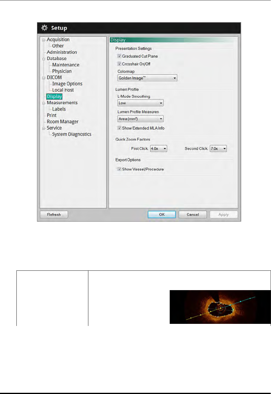
User Interface Reference
Setup - Display Menu
ILUMIEN OPTIS System
Instructions for Use 10-21
Setup - Display Menu
Table 10-12: Setup - Display Menu Settings
Graduated Cut
Plane
Check this checkbox to add graduated marks to the cut plane indi-
cator to use as scale marks.
Figure 10-11: Setup - Display Menu
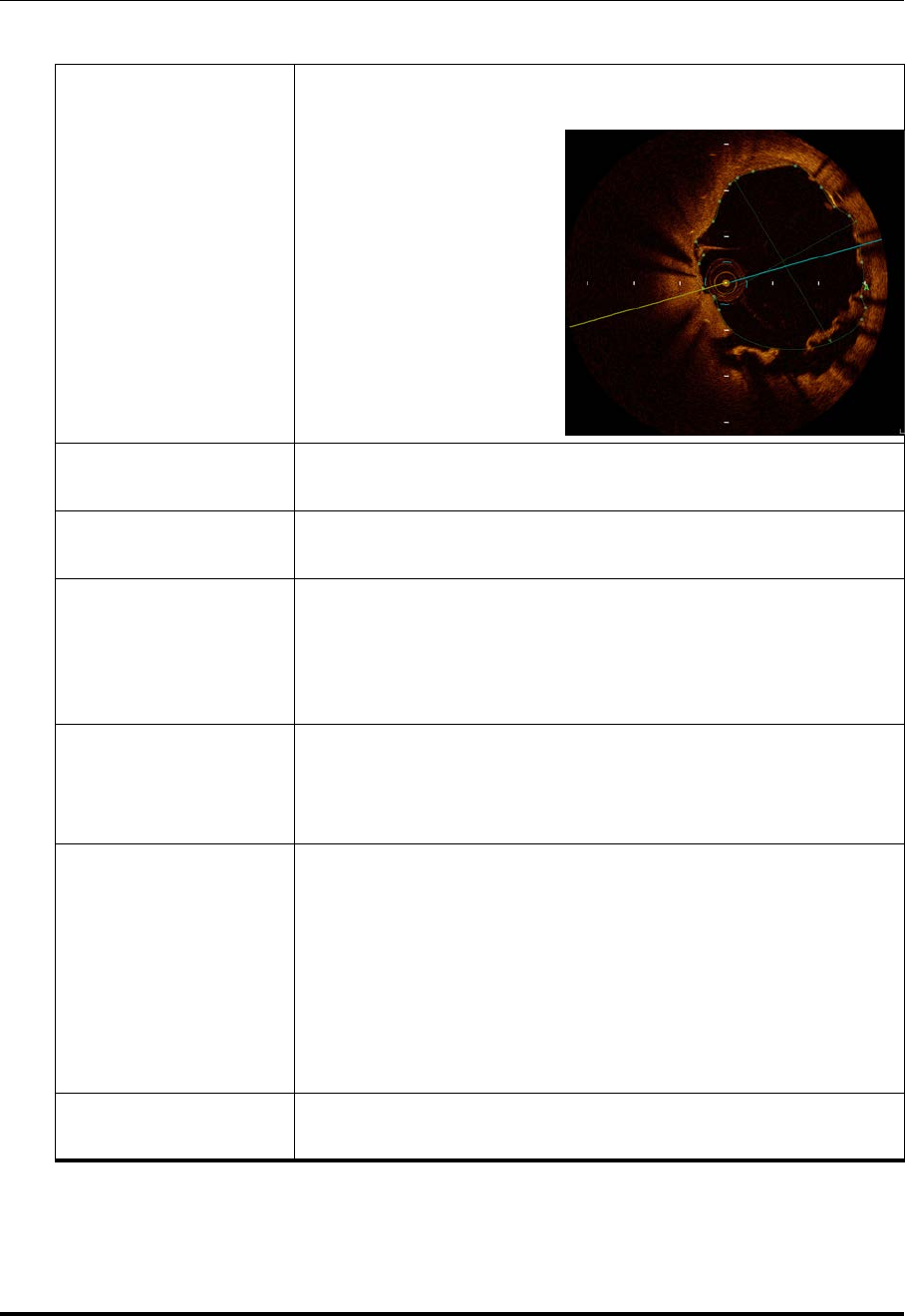
User Interface Reference
Setup - Display Menu
St. Jude Medical
10-22 Part Number ARTUS100109403
Crosshair On/Off
Check this checkbox to add scaled crosshairs to the cross section
view.
Colormap Click the arrow on the Colormap drop-down menu to display the
list of colors. Click a color to select it.
L-Mode (Smoothing) Click to select the amount of smoothing (averaging) for L-Mode
views. The default setting is Low.
Lumen Profile
Measures
Select the type of measurements to be represented in the Lumen
Profile view. The default value is Mean Diameter. When Mean
Diameter is selected, %DS values are displayed in the Lumen Pro-
file view. These values are changed to %AS when Area is
selected.
Show Extended MLA
Info
Check to include the %DS (or %AS) values of the MLA with
respect to both the Proximal and Distal Reference frames. This is
in addition to the %DS (or %AS) value of the MLA with respect to
the mean of the Proximal and Distal reference frames.
Quick Zoom Factors
Select the first click and second click zoom factor for the 2D, 3D,
and Angio displays. Available choices for the first click setting are:
2.0x; 3.0x; 4.0x; 5.0x; 6.0x; and 7.0x. The second click setting
can be set to a zoom factor greater than or equal to the first click
setting. If the first click and second click settings are set to the
same value then the first click will zoom in and the second click
will zoom out. If the two settings are different then the first and
second clicks will zoom in to their zoom factor, and the third click
will zoom out. The default values are 3.0x and 6.0x respectively.
Show Vessel/Procedure Check this box to present the Vessel and Procedure value on the
exported DICOM image. The default is unchecked.
Table 10-12: Setup - Display Menu Settings (continued)
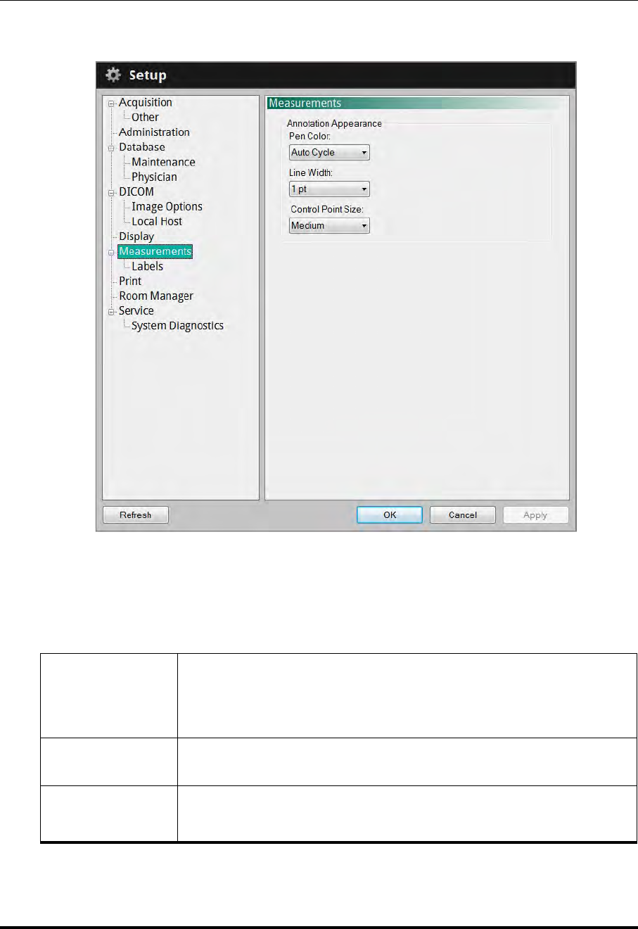
User Interface Reference
Setup - Measurements Menu
ILUMIEN OPTIS System
Instructions for Use 10-23
Setup - Measurements Menu
Table 10-13: Setup - Measurements Menu Settings
Pen Color
List of pen colors that can be used for subsequent measurements and
calculations. If Auto Cycle is selected, the pen color used for measure-
ments is automatically changed to the next color after a new measure-
ment is completed.
Line Width List of line widths that can be used for subsequent measurements and
calculations. The default is 1pt.
Control Point
Size
List of point sizes that can be used for subsequent length and two-point
circular area measurements. The default is Medium.
Figure 10-12: Setup - Measurements Menu
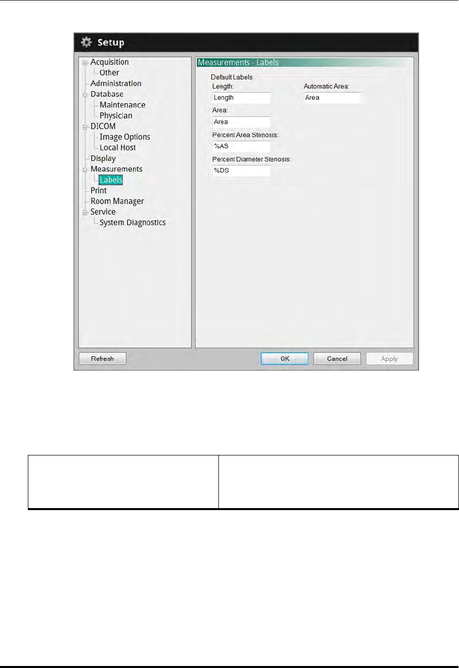
User Interface Reference
Setup - Measurements/Labels Menu
St. Jude Medical
10-24 Part Number ARTUS100109403
Setup - Measurements/Labels Menu
Table 10-14: Setup - Measurements/Labels Menu Settings
Default Labels
Label text that will be used when making the indi-
cated type of measurement.
Click and type in any field to change that label.
Figure 10-13: Setup - Measurements/Labels Menu
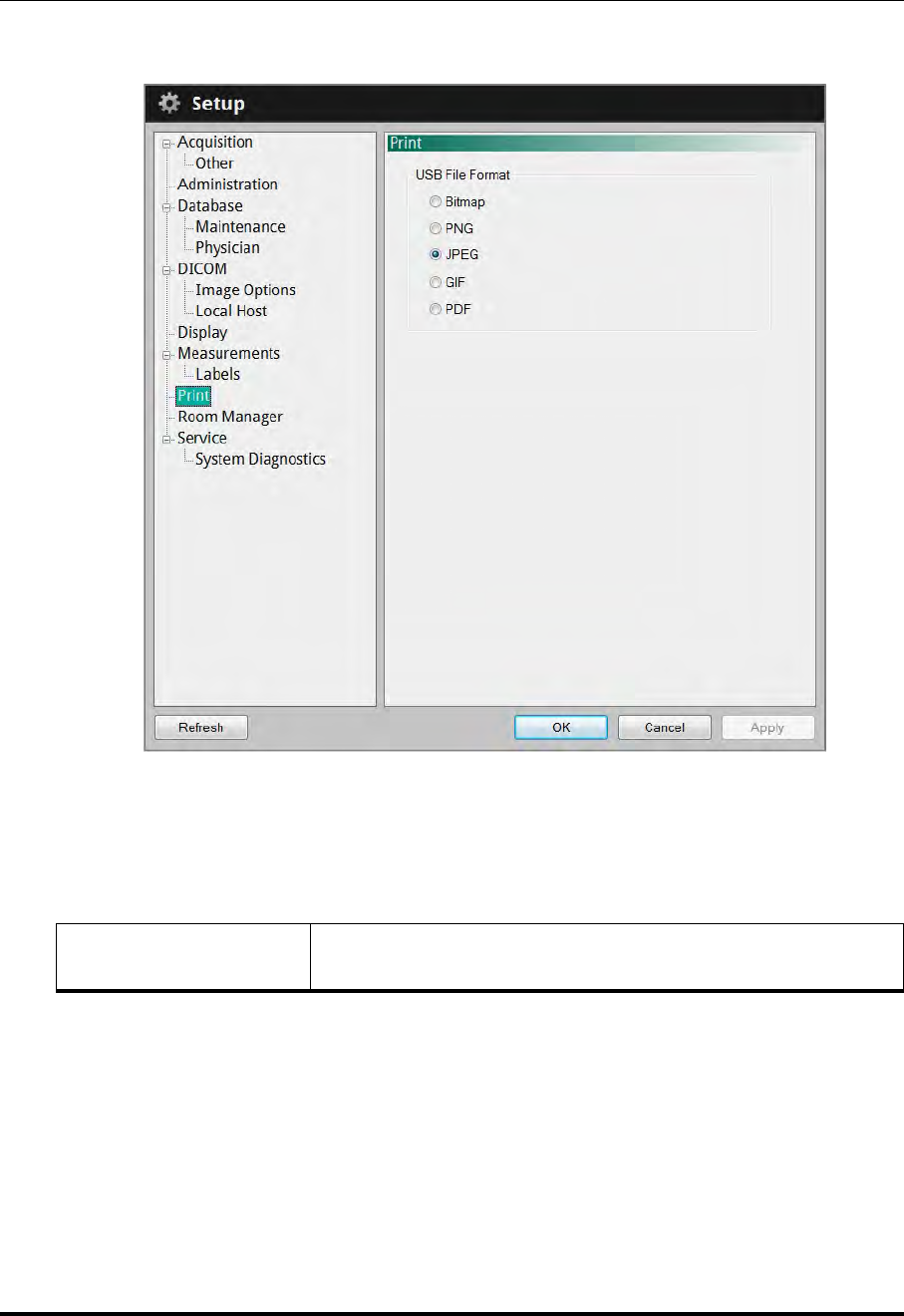
User Interface Reference
Setup - Print Menu
ILUMIEN OPTIS System
Instructions for Use 10-25
Setup - Print Menu
Table 10-15: Setup - Print Menu Settings
USB File Format Click to choose the format used when printing a file to a USB
drive.
Figure 10-14: Setup - Print Menu
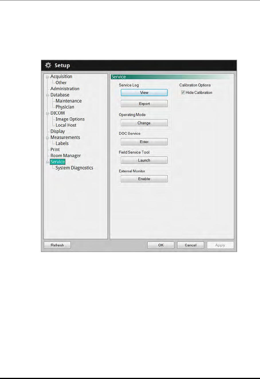
User Interface Reference
Setup - Service Menu
St. Jude Medical
10-26 Part Number ARTUS100109403
Setup - Service Menu
The Service menu in the Setup dialog box displays service logs to help St. Jude Medical
Service analyze problems which may occur during system operation. If you encounter
problems while using the system, you may be asked to access and report information from
this menu.
Figure 10-15: Setup - Service Menu
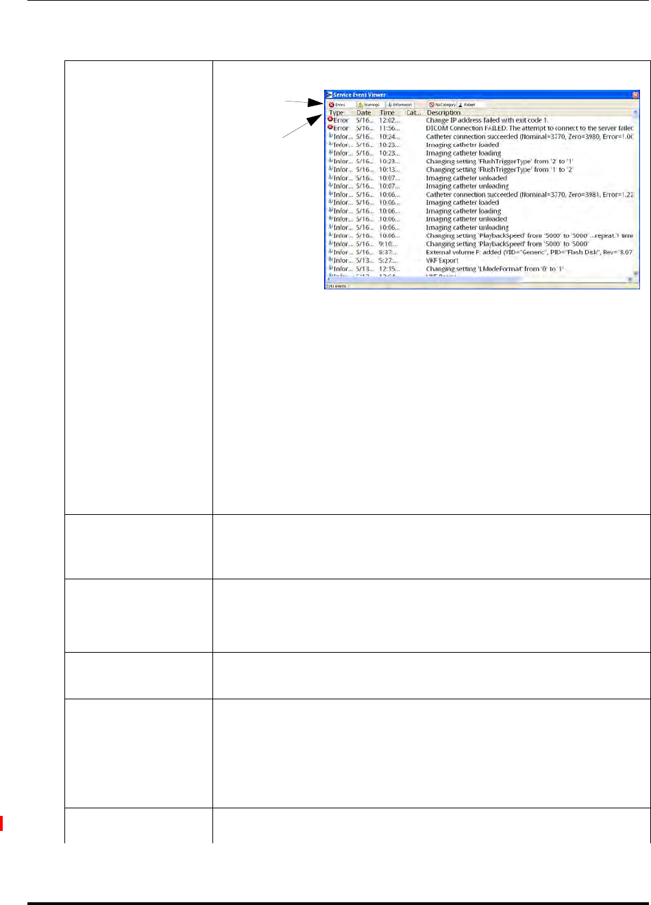
User Interface Reference
Setup - Service Menu
ILUMIEN OPTIS System
Instructions for Use 10-27
Table 10-16: Setup - Service Menu Settings
Service Log
(View)
Click the View button to open the Service Event Viewer.
Click on a column header to sort the patients according to data
in that column. Click the buttons at the top to show or hide cate-
gories of information:
•Errors - lists all the operating errors logged by the system.
•Warnings - lists all the Warning prompts displayed during opera-
tion.
•Information - lists selected system status events which may help
diagnose problems.
•No Category - Displays entries that do not have a Category listed.
•Patient - lists all changes and import/export of patient data.
Service Log
(Export)
Click the Export button to open the Transfer Event Log Files menu,
to export the Event Log files to a specified drive. See “Transfer Event
Log Files Menu” on page 9-11 for more information.
Operating Mode
Click the Change button to open the System Configuration Utility
window to change the application type and/or operating mode.
A password is required to open the configuration utility.
DOC Service Click Enter to perform DOC maintenance, including cleaning or
replacing the Optical Adapter.
Field Service Tool
Click Launch to start the Field Service Utility.
NOTE: The service utility is for use by trained Field Service Engi-
neers.
A password is required to open the service utility.
External Monitor This feature is not used on the OPTIS Integrated system.
Buttons
Headers

User Interface Reference
Setup - Service Menu
St. Jude Medical
10-28 Part Number ARTUS100109403
Calibration
Options
The Hide Calibration checkbox controls the display of the calibra-
tion sequence when a catheter is first connected to the DOC.
Checked - The calibration sequence is hidden.
Unchecked - The calibration sequence is displayed on screen.
Table 10-16: Setup - Service Menu Settings (continued)
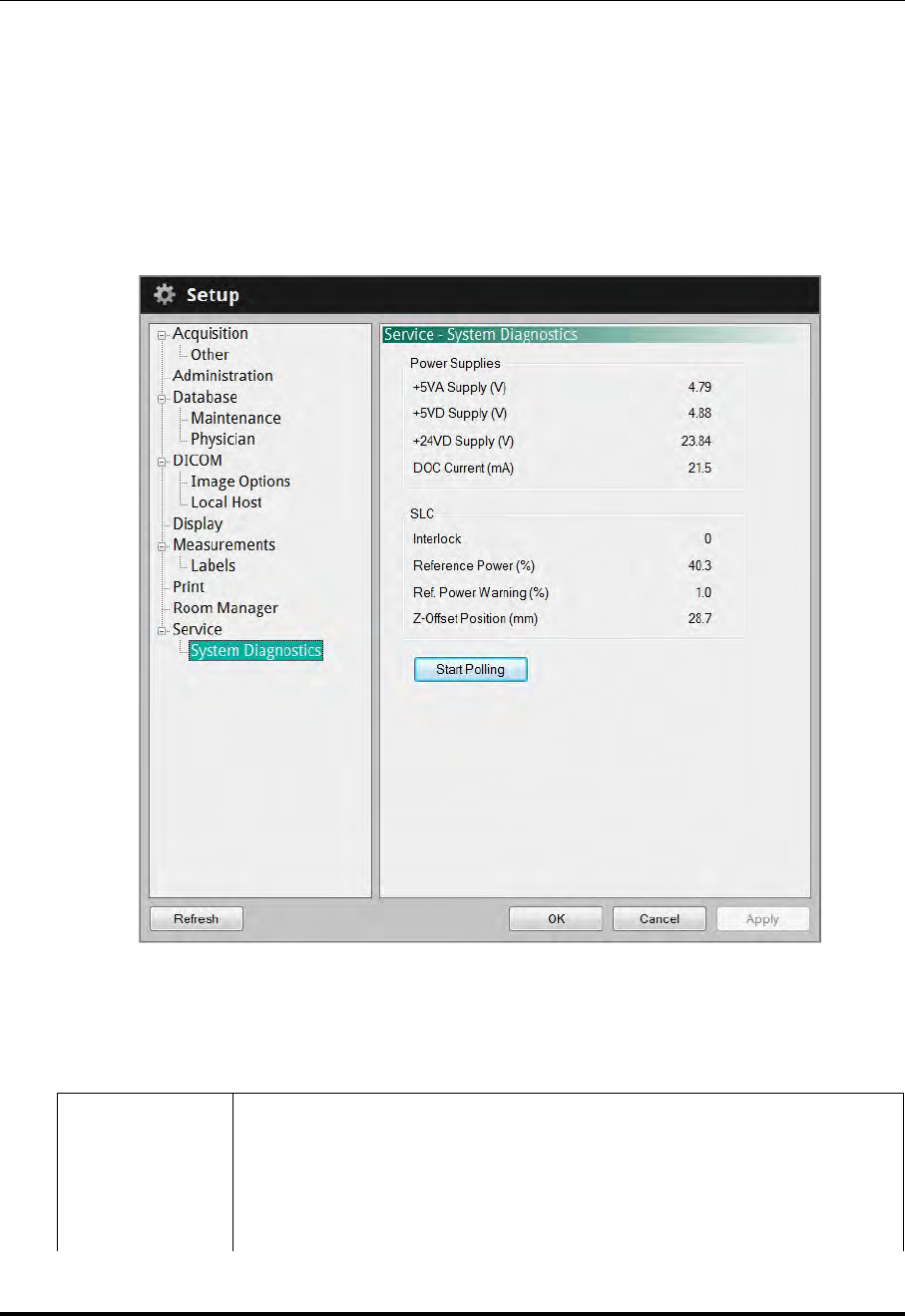
User Interface Reference
Setup - Service/System Diagnostics Menu
ILUMIEN OPTIS System
Instructions for Use 10-29
Setup - Service/System Diagnostics Menu
The System Diagnostics menu in the Setup dialog box is provided to help St. Jude Med-
ical Service monitor and analyze signal levels in the imaging engine either in real time or
at the time a recording was made. When the tab is selected the system immediately dis-
plays the detected signal levels while in Acquisition mode or the signal values when the
current image was captured when in Playback mode. If you encounter problems while
using the system, you may be asked to access and report information from this tab
Table 10-17: Setup - Service/System Diagnostics Menu Settings
Power Supplies +5VA Supply - The +5 volt AC power supply voltage.
+5VD Supply - The +5 volt DC power supply voltage.
+24VD Supply - The +24 volt DC power supply voltage.
DOC Current - The current being drawn by the DOC in mA.
Figure 10-16: Setup - Service/System Diagnostics Menu

User Interface Reference
Setup - Service/System Diagnostics Menu
St. Jude Medical
10-30 Part Number ARTUS100109403
SLC Interlock - Displays the SLC interlock state.
Reference Power - Displays the reference power value in %.
Ref. Power Warning - Reference Power Warning value in %.
Z-Offset Position - Z-Offset Position value in millimeters.
Start Polling /
Stop Polling Starts/stops automatic update of these values, in real time, every 50 milli-
seconds.
NOTE: During playback, the Polling button is disabled, and the values
represent the signal levels of the imaging engine at the image
recording time.
Table 10-17: Setup - Service/System Diagnostics Menu Settings (continued)

ILUMIEN OPTIS System
Instructions for Use 11-1
Safety Information 11
Although the ILUMIEN OPTIS System conforms to laser emission standards and both inter-
national and European safety and electromagnetic compatibility standards, the system is
intended for use only by medical personnel who have received ILUMIEN OPTIS System
training. Only a trained operator can determine if ILUMIEN OPTIS System use is appropri-
ate. An awareness of the system’s limitations is essential to making that determination
and assuring safe operation for both operator and patient.
This chapter includes:
• Precautions to assure patient and operator safety.
• How to avoid optical, electrical, explosion, and defibrillator hazards.
• How to make proper electrical connections.
• System imaging limitations.
• How to trace the source of electromagnetic interference.
CAUTION: Before using the ILUMIEN OPTIS System for the first time, be sure to
read and understand all of the information in this chapter.
NOTE: The ILUMIEN OPTIS System complies with FDA performance standards for
laser products except for deviations pursuant to laser Notice No. 50, dated
July 26, 2001.
NOTE: LightLab Imaging, Inc. hereby declares that OPTIS Integrated system is in
compliance with the essential requirements and other relevant provisions
of Directive 1999/5/EC. A copy of the Full Declaration of Conformity can
be obtained by contacting the EU Representative.

Safety Information
Patient Safety
St. Jude Medical
11-2 Part Number ARTUS100109403
Patient Safety
The ILUMIEN OPTIS System is intended for use only by medical personnel trained in its
operation and skilled in the clinical procedures to be used.
To avoid any potential hazard to patients, follow the precautions outlined in this section.
CAUTION: Use only the Dragonfly Imaging catheters with the ILUMIEN OPTIS
System. Use of other types of catheters may result in unsafe conditions
for the patient and damage the ILUMIEN OPTIS System.
General
WARNING: Failure to follow the guidelines described in these Instructions for Use
and in the Instructions for Use provided with the accessories may
result in injury to patients and damage to equipment.
• Only use Dragonfly™ Imaging Catheters. Always use under appropriate imaging
guidance (endoscopy, x-ray fluoroscopy, or other appropriate guidance method).
• Only use PressureWire pressure transducers to report aortic distal pressure. Always
use under appropriate imaging guidance (endoscopy, x-ray fluoroscopy, or other
appropriate guidance method).
• Always read and follow the Instructions for Use supplied with the Dragonfly Imag-
ing Catheter and with the PressureWire catheter.
• Always use controls, make adjustments and perform procedures as specified in
these Instructions for Use.
Techniques to Minimize Patient Exposure
The ILUMIEN OPTIS System meets the performance standards of laser-emitting products
as established by IEC 60825-1. Although no harmful effects have been demonstrated for
the near-infrared light wavelengths, intensities, and exposure times used during examina-
tions with the ILUMIEN OPTIS System, St. Jude Medical recommends that you carefully
read the warning labels on the system (see Figure 11-1) and follow these examination
guidelines:
• Use OCT only when there is a good reason to do so.
• Use techniques that enable quick collection of clinical data and shorten procedure
time.
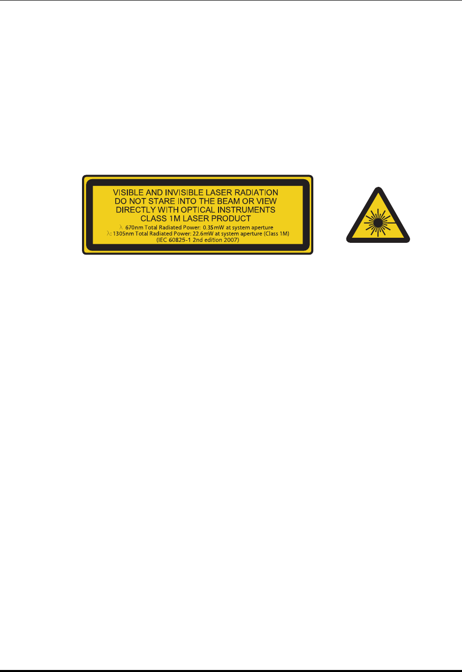
Safety Information
Operator Safety
ILUMIEN OPTIS System
Instructions for Use 11-3
Operator Safety
Avoiding Operator Light Emission Hazards
To avoid any potential light emission hazards to yourself or patients, adhere to the infor-
mation provided in the safety labels that are located on the system (see Figure 11-1), and
observe the precautions outlined in this section.
WARNING: Failure to follow any of these precautions may cause possible serious
damage to your eyes.
• Avoid eye exposure. Do not look at or stare directly into the beam. Doing so may
damage your eyes.
• Never view the laser output with optical instruments (for example, eye loupes, mag-
nifiers, and microscopes). Doing so may damage your eyes.
• Use controls, make adjustments, and perform procedures only as specified in these
Instructions for Use.
Repetitive Strain Injury (RSI)
Repetitive use of a mouse and keyboard has been associated with Carpal Tunnel Syn-
drome (CTS) and related musculoskeletal problems. Follow these suggestions to help
prevent these problems:
• Maintain your joints in optimum positions with a balanced posture, avoiding:
• Static postures.
• Exertion of force during repetitive motions.
• Wrist flexion or deviation.
• Position the keyboard and monitor to minimize reaching and stretching.
• Take frequent breaks to give tissues time to recuperate from awkward positions and
repetitive movements.
Figure 11-1: Connector Panel Laser Safety Labels

Safety Information
Moving the System
St. Jude Medical
11-4 Part Number ARTUS100109403
Moving the System
When moving the system, observe these precautions:
WARNING: Failure to follow any of these precautions may lead to a system tipping
hazard, causing possible injury to people and damage to the system.
• Be sure to turn off and disconnect the system cord from the wall outlet before begin-
ning a move.
• Position the DOC cable appropriately before moving the system.
• The system weighs up to 95 kg (209 lbs) with all accessories installed, two people
are required when moving it.
• Make sure that the system’s wheels roll freely before beginning the move. Resolve
any wheel problems before you move the system.
NOTE: Be sure the system brakes are in the up position (unlocked).
• To eliminate the potential danger of the system’s tipping over, avoid ramps that are
steeper than 5 degrees.
• Do not push the system by the monitors or monitor support mount.
• If you must move the system up or down ramps with an incline of more than 5
degrees, use two people.
• Do NOT lift a cart bearing the system to move it over uneven elevator entrances or
other steps and barriers. Instead, find a route that avoids such problems.
NOTE: Wheelchair ramps usually have an incline of less than 5 degrees.
• When using a transport vehicle, be sure that it can handle the weight of the system
components plus passengers.
• If a lift is used be sure the load capacity of the lift can accommodate the weight of
the system components plus passengers.

Safety Information
Avoiding Electrical Hazards
ILUMIEN OPTIS System
Instructions for Use 11-5
Avoiding Electrical Hazards
The isolation transformer in the ILUMIEN OPTIS System provides electrically isolated
power to components supplied with the system or specified as part of the system.
WARNING: All system components except the isolation transformer itself MUST
be powered by, and only by, the isolation transformer in the ILUMIEN
OPTIS System.
This electrical isolation separates the system components, and thus the patient, from dan-
gerous leakage currents. If any of the system’s components are directly connected to a
wall outlet or some power source other than the isolation transformer, the patient and the
operator are no longer safely isolated and may be exposed to dangerous electric currents.
WARNING: Failure to abide by the precautions detailed below causes the system
and its use to be out of compliance with regulations and places the
patient and the operator at risk of injury or death.
• Do NOT use additional cables, extension cords or outlets with the ILUMIEN OPTIS
System.
NOTE: The ILUMIEN OPTIS System’s isolation transformer creates an elec-
trically isolated Patient Interface for invasive imaging. This electri-
cally isolated condition must be maintained throughout the
procedure or during any contact with the patient.
• When transferring files inside the catheterization lab, use only port-powered USB
drives.
WARNING: Inside the catheterization lab only port-powered USB drives
may be connected to the USB port. Connecting externally pow-
ered devices to the USB port in the patient vicinity may compro-
mise electrical isolation and cause patient injury.
NOTE: Outside the catheterization lab, IEC 60950-compliant, externally
powered USB hard drives may be connected to the USB port.
• Do NOT remove system covers. Only qualified personnel should service the sys-
tem. Accidentally contacting the electrical circuits inside the housing could cause
serious injury.
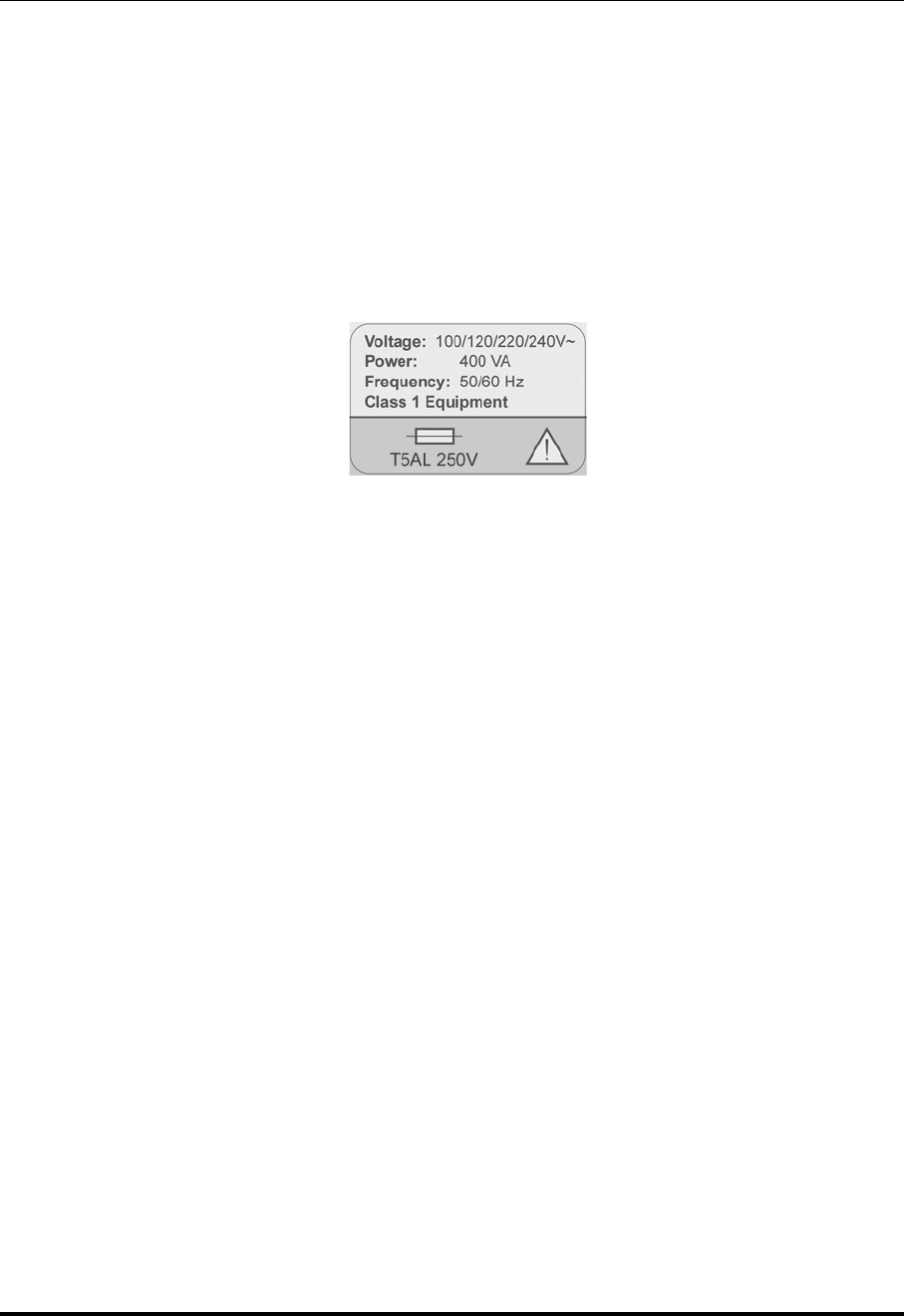
Safety Information
Making Proper Electrical Connections
St. Jude Medical
11-6 Part Number ARTUS100109403
Making Proper Electrical Connections
Ensure the electrical connection for the system is properly rated (see Figure 11-2). Care-
fully follow the safety guidelines described in this section when connecting your system’s
power cord to the hospital or lab’s AC outlet.
WARNING: Failure to follow the electrical connection precautions detailed in this
section causes the system and its use to be out of compliance with reg-
ulations and places the patient and the operator at risk of injury or
death and may damage the equipment.
• Connect the system only to properly grounded (three-hole) hospital-grade AC out-
lets:
• The circuit must accommodate an additional load of up to 400 VA.
• Replacement fuses are available through St. Jude Medical, part number: 11559-02
FUSE
• The power cord is to be used for disconnection from main power.
• Make sure that any devices that connect to the network interface of the ILUMIEN
OPTIS System comply with the appropriate IEC/national standard and are certified
to IEC 60950.
• Use no electrical peripherals within six feet of a patient unless the peripherals
receive power from an isolation transformer that meets medical safety standards.
NOTE: If the ILUMIEN OPTIS System is used with peripherals that are pow-
ered from a separate wall outlet, then the combination is considered
to be a Medical System. It is the user’s responsibility to comply with
IEC 60601-1-1 and test the Medical System according to the require-
ments.
Figure 11-2: Electrical Label

Safety Information
Explosion Hazard
ILUMIEN OPTIS System
Instructions for Use 11-7
Explosion Hazard
WARNING: Do NOT operate the ILUMIEN OPTIS System in the presence of flam-
mable anesthetics. Doing so could lead to an explosion.
System Imaging Limitations
The ILUMIEN OPTIS System is intended for use by medical personnel who have received
training in the use of the system. To determine if system use is appropriate, the trained
user must be aware of system imaging limitations.
CAUTION: Use only the Dragonfly™ Imaging catheters with the ILUMIEN OPTIS
System. Other types of catheters may break if used.
This section includes information about system capabilities and limitations for both ves-
sel and tissue imaging.
Considerations for Optimal Vessel Imaging
The ILUMIEN OPTIS System can be used to image through vessels or to image the inner
surface of certain vessels. Since the Dragonfly catheter is smaller than the diameter of the
vessel being imaged, the position of the catheter in the vessel has an effect on the portion
of the vessel that can be imaged.
• Imaging range is greatest when the imaging catheter is centered in the lumen.
• Imaging range is least when the imaging catheter is placed eccentrically (off-center)
in the lumen, against the wall of the vessel.
Considerations for Optimal Tissue Imaging
The maximum imaging depth within a vessel wall ranges from approximately 0.9 mm to
1.3 mm and is limited by optical attenuation caused by scattering of the optical beam by
microstructures in the vessel. For example, penetration of the OCT beam is deepest in cal-
cified tissue and shallowest in dense fibrotic tissue.

Safety Information
Electromagnetic Compatibility
St. Jude Medical
11-8 Part Number ARTUS100109403
Electromagnetic Compatibility
The ILUMIEN OPTIS System is designed to meet the following electromagnetic compati-
bility standards:
• IEC 60601-1-2 (US and International).
• EN 60601-1-2 (Europe).
Electromagnetic Interference
The system produce images by using digital signal processing techniques that operate in
the radio frequency (RF) energy range. The system is therefore susceptible to interference
generated by other RF energy sources such as medical devices, information technology
products, or radio/television transmission towers. Tracing the source of radiated interfer-
ence can be difficult.
In accordance with the standards identified in these Instructions for Use, no interference
was observed. However, the trained user must determine if an artifact caused by radiated
interference will negatively impact image quality and the subsequent study results.
To help identify the source of electromagnetic interference, ask the following questions:
• Is the interference intermittent or constant?
• Does the interference occur with one catheter only, or with other imaging catheters?
• Is the interference present if the system is moved to a different location in the facil-
ity? Examples: Placing the system close to an ECG cable can increase electromag-
netic interference. Moving the cable or other medical equipment away from the
system can reduce electromagnetic interference.
Please answer these questions before contacting your service representative. The answers
will help a service representative determine if the problem is in the system or in the imag-
ing environment.

Safety Information
Safety Functions Built Into the Ilumien Optis System
ILUMIEN OPTIS System
Instructions for Use 11-9
Safety Functions Built Into the ILUMIEN OPTIS System
The following safety functions have been built into the system:
• The system disables light output and disables all motors in these situations:
• The optical fiber stops rotating due to mechanical failure.
• Communication is lost between the imaging engine and the DOC.
• Communication is lost between the computer and the imaging engine.
• Pressing the Stop button on the DOC disables power to the DOC and laser output
(see “The Drive-motor and Optical Controller (DOC)” on page 1-10).

Safety Information
Safety Functions Built Into the Ilumien Optis System
St. Jude Medical
11-10 Part Number ARTUS100109403

ILUMIEN OPTIS System
Instructions for Use 12-1
System Specifications 12
System - Safety & Regulatory
Table 12-1: System Safety & Regulatory Specifications
Category Specifications
Regulatory Approvals US 510(k) clearance.
Safety standards system
meets: IEC 60601-1:2005 + CORR. 1 (2006) + CORR. 2 (2007)
EN60601-1: 2006, “Medical Electrical Equipment, Part 1:
General Requirements for Safety”
EN60601-1-2: 2007, Electromagnetic Radiated Emissions
Requirements for Medical Electrical Equipment - Group 1
Equipment, Class B for Non-Life Supporting Equipment
UL60601-1: 2003, “Medical Electrical Equipment, Part 1:
General Requirements for Safety”
CAN/CSA C22.2 No. 60601-1:2008, “Medical Electrical
Equipment, Part 1: General Requirements for Safety”
IEC 60825-1, 2nd Ed., 2007: Safety of Laser Products
Electromagnetic compatibil-
ity (EMC) Refer to Table 12-5, Table 12-6, Table 12-7, and Table 12-8
for detailed specifications.

System Specifications
System - Safety & Regulatory
St. Jude Medical
12-2 Part Number ARTUS100109403
Classifications
Type of protection, shock Class 1
Degree of protection,
shock Type CF
• DOC with catheter (CF label at DOC cable exit on Con-
nector Panel)
Degree of protection,
ingress Console - IPX0
DOC - IPX0, use with Sterile DOC cover for ingress protec-
tion
Method of Disinfection Console and DOC will withstand without damage or deterio-
ration disinfection by wiping with common hospital disinfec-
tants including Cidex (Glutaraldehyde 3.4%).
Flammable mixtures Not for use in presence of flammable anesthetic mixture with
air or with oxygen or nitrous oxide.
Mode of operation Continuous
Leakage & Auxiliary Current
Chassis leakage current < 100 µa rms normal condition
< 500 µa rms single-fault condition
Patient leakage current Measured at patient end of DOC:
< 10 µa rms normal condition
< 50 µa rms single-fault condition
Software Safety Features
The computer and software are designed with the following security features. These features
do not require any user configuration or action.
• Prevents unauthorized access to the operating system.
• Prevents installation or execution of unauthorized software
• Prevents infiltration via Ethernet connection.
• Performs data integrity check when archiving data to external media.
Table 12-1: System Safety & Regulatory Specifications (continued)
Category Specifications

System Specifications
System - Electrical and Physical
ILUMIEN OPTIS System
Instructions for Use 12-3
System - Electrical and Physical
Table 12-2: System Electrical and Physical Specifications
Parameter Specification
Power Input
Line voltage 100/120/220/240 VAC ±10%, user selectable
50/60 Hz ±1 Hz
Power consumption Active: < 400 VA
Standby: < 30 VA
Transport and Storage Conditions (Permissible ranges)
Ambient temp -25 to +50 degrees C
Relative humidity 10% - 95%, including condensing
Atmospheric pressure 500 to 1060 mBar
Operating Conditions
Ambient temperature +10 to +32 degrees C
Relative humidity 10% to 85%, non-condensing
Atmospheric pressure 700 to 1060 mBar
Mechanical Specifications
Weight 95 kg (209 lbs) max with all accessories
Overall Dimensions 145 cm H x 61 cm W x 71 cm D ±5 mm

System Specifications
Imaging Specifications
St. Jude Medical
12-4 Part Number ARTUS100109403
Imaging Specifications
Table 12-3: Imaging Specifications
Parameter Specification
Optical Parameters - Measured at System Aperture (DOC Optical Port)
Scanning Laser Source Optical
Power 22.6 mW maximum @ 1305 nm ±55 nm
(Class 1M Laser Output per IEC 60825-1)
Visible Laser Optical Power 1.45 mW maximum @ 670 nm (nominal)
(Class 1M Laser Output per IEC 60825-1)
Pullback Parameters
Pullback Range 75 mm
(If connected to a C7 Dragonfly catheter, the range is
54 mm.)
Pullback Speed Settings 18.0 mm/sec, 36.0 mm/sec
(If connected to a C7 Dragonfly catheter, the speed set-
tings are 10.0 mm/sec, 20.0 mm/sec, 25.0 mm/sec.)
General Scan Parameters
A-Scan Range in Air 7.0 mm
A-Scan Range in Contrast 4.83 mm
Diameter Measurement Accuracy 7% ±0.1 mm
Area Measurement Accuracy 10% ±0.1 mm2
Axial Resolution 20 µm in tissue
Optical Sensitivity 90 db minimum
A-Scans per second 90 kHz (nominal)
Frame Rate 180 frames/second (Hz)
(If connected to a C7 Dragonfly catheter, the Frame
Rate is 100 frames/second (Hz).)

System Specifications
FFR Specifications
ILUMIEN OPTIS System
Instructions for Use 12-5
FFR Specifications
Table 12-4: FFR Specifications
Parameter Specification
AO Pressure (Wi-Box to ILUMIEN OPTIS System)
Operating pressure -200 to +450 mm Hg
Accuracy +/- 1 mm Hg or +/- 1% of reading, whichever is greater
PW Pressure
Operating pressure -30 to +300 mm Hg
Accuracy ±1 mm Hg plus ±1% of reading (-30 to 50 mm Hg)
±3% of reading (50 to 300 mm Hg)
AO Pressure (Wi-Box to hemodynamic recording system)
Direct galvanic connection
Max pressure shift <2 mm Hg
Radio Specification
Frequency range 2.4000 - 2.4835 GHz
Type Frequency hopping spread spectrum (FHSS)
Range 0 - 4 m
Delay time <20 ms

System Specifications
Electromagnetic Emissions
St. Jude Medical
12-6 Part Number ARTUS100109403
Electromagnetic Emissions
Table 12-5: Guidance and Manufacturer’s Declaration - Electromagnetic Emissions
The ILUMIEN OPTIS System is intended for use in the electromagnetic environment
specified below. The customer or user of the ILUMIEN OPTIS System should assure
that it is used in such an environment.
Emissions Test Compliance Electromagnetic Environment - Guidance
RF emissions
CISPR 11 Group 1 The ILUMIEN OPTIS System uses RF energy only
for its internal function. Therefore, its RF emis-
sions are very low and not likely to cause any
interference with nearby electronic equipment.
RF emissions
CISPR 11 Class B The ILUMIEN OPTIS System is suitable for use in
all establishments, including domestic establish-
ments and those directly connected to the public
low-voltage power supply network that supplies
buildings used for domestic proposes.
Harmonic emissions
IEC 61000-3-2 Class A
Voltage fluctuations/
flicker emissions
IEC 61000-3-3
Complies

System Specifications
Electromagnetic Immunity
ILUMIEN OPTIS System
Instructions for Use 12-7
Electromagnetic Immunity
Table 12-6: Guidance and Manufacturer’s Declaration - Electromagnetic Immunity
The ILUMIEN OPTIS System is intended for use in the electromagnetic environment
specified below. The customer or user of the ILUMIEN OPTIS System should assure
that it is used in such an environment.
Immunity Test IEC 60601 Test
Level Compliance Level Electromagnetic
Environment -
Guidance
Electrostatic dis-
charge (ESD)
IEC 61000-4-2
± 6 kV contact
± 8 kV air ± 6 kV contact
± 8 kV air Floors should be wood,
concrete or ceramic tile.
If floors are covered
with synthetic material,
the relative humidity
should be at least 30%.
Electrical fast tran-
sient/burst
IEC 61000-4-4
± 2 kV for power sup-
ply lines
± 1 kV for input/out-
put lines
± 2 kV for power sup-
ply lines
± 1 kV for input/out-
put lines
Mains power quality
should be that of a typi-
cal commercial or hos-
pital environment.
Surge
IEC 61000-4-5 ± 1 kV lines(s) to
line(s)
± 2 kV lines(s) to
earth
± 1 kV lines(s) to
line(s)
± 2 kV lines(s) to
earth
Mains power quality
should be that of a typi-
cal commercial or hos-
pital environment.
Voltage dips, short
interruptions and
voltage variations
on power supply
input lines
IEC 61000-4-11
< 5 % UT
(>95% dip in UT) for
0.5 cycle
40% UT
(>60% dip in UT)
for 5 cycles
70% UT
(30% dip in UT) for
25 cycles
<5% UT
(>95% dip in UT) for
5 seconds
< 5% UT
(>95% dip in UT) for
0.5 cycle
40% UT
(>60% dip in UT) for
5 cycles
<70% UT
(>30% dip in UT) for
25 cycles
<5% UT
(>95% dip in UT) for
5 seconds
Mains power quality
should be that of a typi-
cal commercial or hos-
pital environment. If
the user of the ILUMIEN
OPTIS System requires
continued operation
during power mains
interruptions, it is rec-
ommended that the
ILUMIEN OPTIS be pow-
ered from an uninter-
ruptible power supply
or battery.
NOTE: UT is the AC mains voltage prior to application of the test level.

System Specifications
Electromagnetic Immunity
St. Jude Medical
12-8 Part Number ARTUS100109403
Power frequency
(50/60 Hz) magnetic
field
IEC 61000-4-8
3 A/m 3 A/m Power frequency mag-
netic fields should be at
levels characteristic of
a typical commercial or
hospital environment.
Table 12-6: Guidance and Manufacturer’s Declaration - Electromagnetic Immunity
The ILUMIEN OPTIS System is intended for use in the electromagnetic environment
specified below. The customer or user of the ILUMIEN OPTIS System should assure
that it is used in such an environment. (continued)
Immunity Test IEC 60601 Test
Level Compliance Level Electromagnetic
Environment -
Guidance
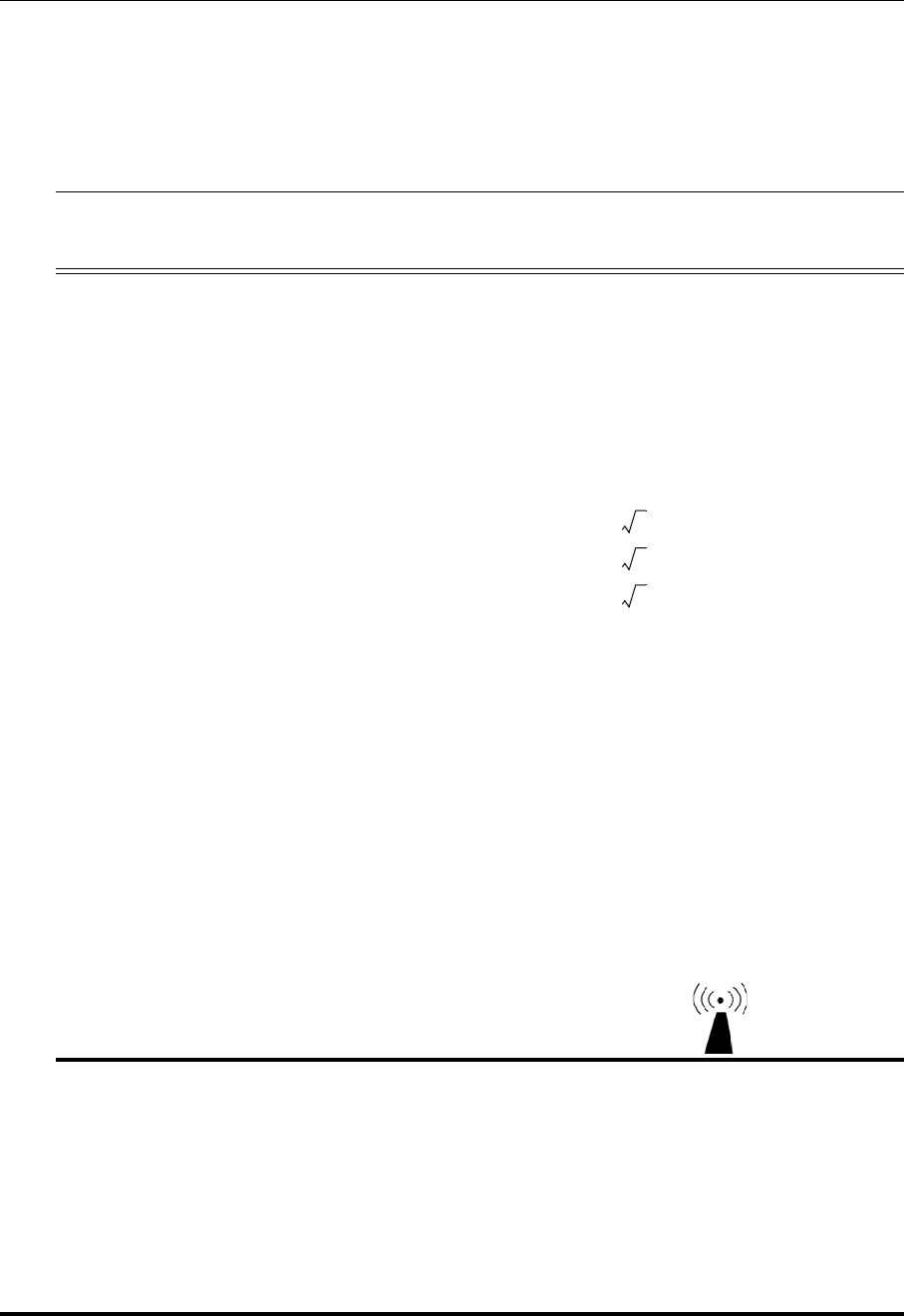
System Specifications
Electromagnetic Immunity
ILUMIEN OPTIS System
Instructions for Use 12-9
NOTE 1: At 80 MHz and 800 MHz, the higher frequency range applies.
NOTE 2: These guidelines may not apply in all situations. Electromagnetic propagation
is affected by absorption and reflection from structures, objects, and people.
Table 12-7: Guidance and Manufacturer’s Declaration - Electromagnetic Immunity
The ILUMIEN OPTIS System is intended for use in the electromagnetic environment
specified in this section. The customer or user of the ILUMIEN OPTIS System should
assure that it is used in such an environment.
Immunity Test IEC 60601
Test Level Compliance
Level Electromagnetic Environment -
Guidance
Conducted RF
IEC 61000-4-6
Radiated RF
IEC 61000-4-3
3 Vrms
150 kHz to 80
MHz
3 V/m
80 MHz to 2.5
GHz
3 Vrms
3 V/m
Portable and mobile RF communica-
tions equipment should be used no
closer to any part of the ILUMIEN OPTIS
System, including cables, than the rec-
ommended separation distance calcu-
lated from the equation applicable to the
frequency of the transmitter.
Recommended separation distance
80 MHz to 800 MHz
800 MHz to 2.5 GHz
Where P is the maximum output power
rating of the transmitter in Watts (W)
according to the transmitter manufac-
turer and d is the recommended separa-
tion distance in meters (m).
Field strengths from fixed RF transmit-
ters, as determined by an electromag-
netic site surveya, should be less than
the compliance level in each frequency
rangeb.
Interference may occur in the vicinity of
equipment marked with this symbol:
d1.2P=
d1.2P=
d2.3P=

System Specifications
Electromagnetic Immunity
St. Jude Medical
12-10 Part Number ARTUS100109403
a Field strengths from fixed transmitters, such as base stations for radio (cellu-
lar/cordless) telephones and land mobile radios, amateur radio, AM and FM radio broad-
cast and TV broadcast cannot be predicted theoretically with accuracy. To assess the
electromagnetic environment due to fixed RF transmitters, an electromagnetic site survey
should be considered. If the measured field strength in the location in which the ILUMIEN
OPTIS System is used exceeds the applicable RF compliance level above, the ILUMIEN
OPTIS System should be observed to verify normal operation. If abnormal performance is
observed, additional measures may be necessary, such as re-orienting or relocating the
ILUMIEN OPTIS System.
b Over the frequency range 150 kHz to 80 MHz, field strengths should be less than
3 V/m.

System Specifications
Recommended Separation Distances
ILUMIEN OPTIS System
Instructions for Use 12-11
Recommended Separation Distances
For transmitters rated at a maximum output power not listed above, the recommended
separation distance d in meters (m) can be estimated using the equation applicable to the
frequency of the transmitter, where P is the maximum output power rating of the transmit-
ter in watts (W) according to the transmitter manufacturer.
NOTE 1: At 80 MHz and 800 MHz, the separation distance for the higher frequency
range applies.
NOTE 2: These guidelines may not apply in all situations. Electromagnetic propagation
is affected by absorption and reflection from structures, objects, and people.
Table 12-8: Recommended separation distances between portable and mobile RF com-
munications equipment and the ILUMIEN OPTIS System
The ILUMIEN OPTIS System is intended for use in an electromagnetic environment
in which radiated RF disturbances are controlled. The customer or the user of the
ILUMIEN OPTIS System can help prevent electromagnetic interference by maintain-
ing a minimum distance between portable and mobile RF communications equip-
ment (transmitters) and the ILUMIEN OPTIS System as recommended below,
according to the maximum output power of the communications equipment.
Rated maximum
output power of
transmitter Separation distance according to frequency of transmitter m
W 150 kHz to 80 MHz 80 MHz to 800 MHz 800 MHz to 2.5 GHz
0.01 0.12 0.12 0.23
0.1 0.38 0.38 0.73
1 1.2 1.2 2.3
10 3.8 3.8 7.3
d1.2P=
d1.2P=
d2.3P=

System Specifications
FCC Statement
St. Jude Medical
12-12 Part Number ARTUS100109403
FCC Statement
This equipment has been tested and found to comply with the limits for a Class A digital
device, pursuant to Part 15 of the FCC Rules. These limits are designed to provide reason-
able protection against harmful interference when the equipment is operated in a commer-
cial environment. This equipment generates, uses and can radiate radio frequency energy
and, if not installed and used in accordance with the instruction manual, may cause harm-
ful interference to radio communications. Operation of this equipment in a residential
area is likely to cause harmful interference in which case the user will be required to cor-
rect the interference at his own expense.
Operation is subject to the following two conditions: (1) this device may not cause harm-
ful interference, and (2) this device must accept any interference received, including
interference that may cause undesired operation.
Changes or modifications not expressly approved by St. Jude Medical could void the
user’s authority to operate the equipment.
Essential Performance Defined by Operating Mode
During testing, the OCT Imaging System (MN: C8/OPTIS Integrated) was operating as
follows: SSOCT Data Viewer is displaying white noise. The CardioUI Development soft-
ware is running. The probe is active and displaying an image. Image on screen is stable
and without error. Also host PC is pinging the EUT.

ILUMIEN OPTIS System
Instructions for Use Index-1
Index
Symbols
%AS, 7-2, 7-10
%DS, 7-2, 7-12
Numerics
3D Display, 7-23
A
Acquisition mode, 10-29
Adding Points, 7-18
Annotation
adding text, 7-8
text, 7-9
Area Measurements
automatic, 7-6
Auto Cycle Drawing Color, 10-23
Automatic MLA and %DS option, 7-20
B
Black Level, 9-15
Bookmark
clear all bookmarks, 6-10
creating, 6-10
next bookmark, 6-10
previous bookmark, 6-10
C
Calculation
%AS, 7-10
%DS, 7-12
Callout
adding, 7-9
position, 7-9
Callouts
adding, 7-8
Catheter
connection to DOC, 4-5, 5-8
disconnecting from DOC, 5-18
insertion, 5-13
positioning, 5-13
preparation, 5-7
purge, 5-9
removal, 5-18
stop movement, 5-19
Caution, meaning and format, Front-iv
Cleaning, 9-2
Complications, 1-16
Complications from Use, 1-16
Connection
network, 1-8
power, 2-2
USB, 1-8
video, 1-8
Connector Panel
location, 1-4
Contact Information
company, Front-ii
service, 9-2
Contraindications for Use, 1-13
Control Point Size, 10-23
Conventions Used in Manual, Front-iv
Creating a New Patient, 3-6
Cross-section View
zoom, 7-15

Index
D
St. Jude Medical
Index-2 Part Number ARTUS100109403
D
Database
create a new patient, 3-6
import, 8-20
Setup dialog box, 10-7
statistics, 8-26, 10-9
Database Tab, 10-7
Delete
files, 8-23
measurements, 7-19
points, 7-18
Depth Calibration Marks, 5-16
Diagnostics Tab, 10-29
DICOM
viewer, 8-16
DICOM Tab, 10-12
DOC catheter connection, 4-5, 5-8
cleaning optical connection, 9-5
description, 1-10
preparation, 5-6
replacing optical adapter, 9-8
Drive-motor and Optical Controller, 1-10
E
Electrical Connections, 11-6
Electrical Hazards, 11-5
Enable button on DOC, 1-10
External Drive, 8-9, 8-10, 8-12
F
FFR Procedure
catheter connection, 4-5
materials and equipment, 4-1
File Size, 8-6
Files deleting, 8-23
Flush Medium
warning, 1-14
G
Green’s Theorem, 7-6
H
Hazards
electrical, 11-5
explosion, 11-7
light emission, 11-3
repetitive strain injury, 11-3
Home menu, 3-2
I
Image Compression
caution, 7-1, 8-7
Image Format
raw, 8-4
standard, 8-5
Imaging
limitations, 11-7
tissue, 11-7
vessel, 11-7
Imaging Specifications
optical parameters, 12-4
pullback parameters, 12-4
scan parameters, 12-4
Import OCT Files, 8-20
Indications for Use, 1-12
Infection Control, 9-13
Instructions for Use
other manuals, Front-iv
Intended Use, 1-12
L
Length Measurement, 7-5
Line Width, 10-23
Live Mode, 10-29
Live View, 5-3
Live View Button on DOC, 1-10

Index
M
ILUMIEN OPTIS System
Instructions for Use Index-3
L-Mode
caution, 7-3
cut-plane, 5-16
limitations, 6-5
measurements and annotations, 7-3
Lock LED on DOC, 1-10
Log Files, 9-11, 10-26
Lumen Profile, 7-20
M
Maintenance, 9-4
Manual
conventions, Front-iv
Measurement Accuracy, 7-3
Measurement and Annotation tools, 7-2
Measurements
adding points, 7-18
caution, 7-1, 8-7
deleting all measurements, 7-19
deleting individual measurements, 7-19
deleting measurements, 7-19
deleting points, 7-18
editing, 7-17
length, 7-5
moving individual points, 7-18
Minimum Lumen Area, 7-21
MLA, 7-21
Monitor Setup, 2-6
Moving Points, 7-18
Moving System, 11-4
N
Near-infrared Light, 1-1, 11-2
Network Connection, 1-8
Note, meaning and format, Front-iv
O
OCT Database, see Database
OCT Procedure
catheter connection, 5-8
catheter insertion, 5-13
catheter positioning, 5-13
catheter preparation, 5-7
completing procedure, 5-18
DOC preparation, 5-6
materials and equipment, 5-1
recording, 5-16
Operator Safety
light emission hazards, 11-3
moving the system, 11-4
repetitive strain injury, 11-3
Optical Coherence Tomography, 1-1
Optical Parameters, 12-4
Optimal Tissue Imaging, 11-7
Optimal Vessel Imaging, 11-7
P
Patient
acquiring image, 5-16
creating a record, 3-6
minimizing exposure, 11-2
safety, 11-2
Patient Entry
creating, 3-6
Patient Record
Open, Create, 3-1
Pen Color, 10-23
Percent Area Stenosis, 7-2, 7-10
Percent Diameter Stenosis, 7-2, 7-12
PIU. See DOC
Playback Calibration
setting, 6-7
Playback Mode, 10-29
playback range, 6-11
Positioning the System, 2-1
Power
off, 2-4
on, 2-3
Power In, 12-3
Precautions for Use, 1-15

Index
R
St. Jude Medical
Index-4 Part Number ARTUS100109403
Pullback
parameters, 12-4
stop, 5-19
trigger, 10-3
Pullback motion LEDs on DOC, 1-10
Purge Catheter, 5-9
R
Range
playback, 6-11
Raw Format
description, 8-4
Recording
status, 5-16
Recording calibration marks, 5-16
Remote DICOM Store, 8-11
Reviewing
saved images, 6-1
S
Safety
functions, 11-9
operator, 11-3
patient, 11-2
Segmented Lumen, 7-25
Select Measurement
percent area stenosis, 7-10
percent diameter stenosis, 7-12
Select Patient menu, 3-2
Service Tab, 10-26
Setup Dialog Box
Database tab, 10-7
Diagnostics tab, 10-29
DICOM tab, 10-12
Service tab, 10-26
Shutdown
procedure, 2-4
Specifications
electrical and physical, 12-3
electromagnetic, 12-6, 12-7, 12-9
imaging, 12-4
pressure and radio, 12-5
safety and regulatory, 12-1
Standard File Format, 8-6
Standard Format
description, 8-5
Standby View, 5-3
Stop Button on DOC, 1-10
System
components, 1-2
features, 1-1
imaging limitations, 11-7
moving, 11-4
power on, 2-3
setup, 2-1
shut down, 2-4
System Display
during image acquisition, 5-16
System Specifications
classifications, 12-2
leakage & auxiliary current, 12-2
mechanical specifications, 12-3
operating conditions, 12-3
power input, 12-3
software safety features, 12-2
transport and storage conditions, 12-3
T
Text adding, 7-8
display options, 7-9
entry, 7-9
position, 7-9
Tissue Imaging, 11-7
Transfer Messages, 8-24, 8-26
Trigger Type, 10-3
Troubleshooting
connections, 9-15
DOC, 9-15
general, 9-14
imaging, 9-15
PressureWire
power failure, 4-15
U
Unload button on DOC, 1-10

Index
Z
St. Jude Medical
Index-6 Part Number ARTUS100109403

ARTUS100088927
ARTUS100xxxxxx XX??


