Lightolier Lytecaster 1000Lv Users Manual Downlights Instruction Sheets
2015-02-09
: Lightolier Lightolier-Lytecaster-1000Lv-Users-Manual-573065 lightolier-lytecaster-1000lv-users-manual-573065 lightolier pdf
Open the PDF directly: View PDF ![]() .
.
Page Count: 2
INSTRUCTIONSHEETNO.
INSTALLATION PROCEDURE FOR LOW VOLTAGE
REFLECTOR TRIM IN THE 1000LV FRAME-IN KIT lS:1052LV
0s90 Page 1of 2
EAD AND UNDERSTAND THESE INSTRUCTIONS BEFORE INSTALLING FIXTURE.
his fixture is intsndsd for installation in accordance with the National Electrical Code or Iocsl regulations.
3assure full compliance with local codes and regulations, check with your local electrical inepector before
wtallation. To prevent electrical shock, turn off electricity at fuse box before proceeding.
ietain these Instruction for maintenance referenc~
?~%~
FIG. BFIG. CFIG. D
1. FRAME-IN 2. CLOSE4N 3, eNAP-ON 4. PuSH-UP
WARNING: BEFORE INSTALLING REFLEClOR TIRM TO FRAME4N KIT, READ MARKINGS IN REFLEClOR
TRIM AND fN SOCK~ CUP OF FRAME4N KIT TO DEf’ERMINE LAMP WAITAGE AND TYPE APPLICABLE FOR
YOUR lNSTALLATfON. IF IC. TYPE FRAME.fN KIT IS USED, IT MAY BE INSTALLED fN DIRECT CONTACT WITH
INSULATED CEILING. IF ANON IC. TYPE FRAME4N KIT IS USED, DO No INSTALL lNSULATfON WITHIN
3INCHSS OF FIXWRE SIDES OR WIRING .COMPARTMENT, NOR ABOVE FfXTURE IN SUCH AMANNER AS ~
ENTRAP HEAT.
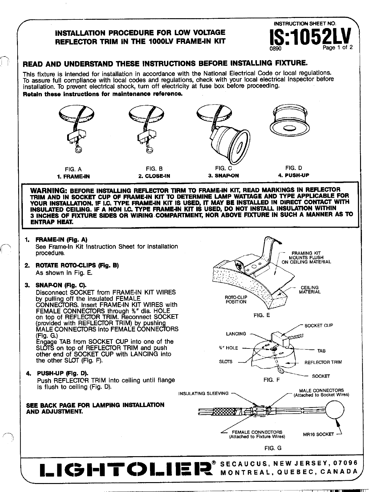
1. FRAME-IN (Fig. A)
4
r-.
See Frame-In Kit Instruction Sheet for installation
procedwe. ,– FRAMINGKIT
MOUNTSFLUSH
!.;
!. R~ATE RUIO-CLIPS (Fig. B) ,.,’ ON CEILINGMATERIAL
0“ \
As shown in Fig. E. ... $1...-
.. .. . . .
. . ..
: ,,..,.,,::.:,.;.
LSNARON (Fig. C).
Disconnect SOCKET from FRAME-IN KIT WIRES CEILING
-.:.“.~.-:. MATERIAL
by pulling off the insulated FEMALE R~-CLIP ““:-~~< ;
CONNECTORS. Insert FRAME-IN KIT WIRES with POSITION ,., ,.
FEMALE CONNECTORS through %“ dia HOLE
on top of REFLECTOR TRIM. Reconnect SOCKET FIG. E
(provided with REFLECTOR TRIM) by pushing
MALE CONNECTORS into FEMALE CONNECTORS –SOCKETGUp
(Fig. G.)
*
LANCING
Engage TAB from SOCKET CUP into one of the . . .
SLOTS on top of REFLECTOR TRIM and push i“ HOLE ,* .
other end of SOCKET CUP with LANCING into ,= TAe
the other SLOT (Fig. F). SLOTS ,} REFLECTORTRIM
4. PUSH-UP (Fig. D).
Push REFLECTCR TRIM into ceiling until flange FIG. FSOCKET
is flush to ceiling (Fig. D).
INSULATINGSLEEVING MALECONNECTORS
[Altachedto Sooketwires)
SEE BACK PAGE FOR LAMPING INSTALLATION
AND ADJUSTMENT.
FEMALEGONNECTORS
(Attachedto FixtureWires)
FIG. G
D-9 C31”ITC>I-I Is 1? :V:::::;,N:;::::,E:; :Y::
IS1052LV
0890
Page 2of 2
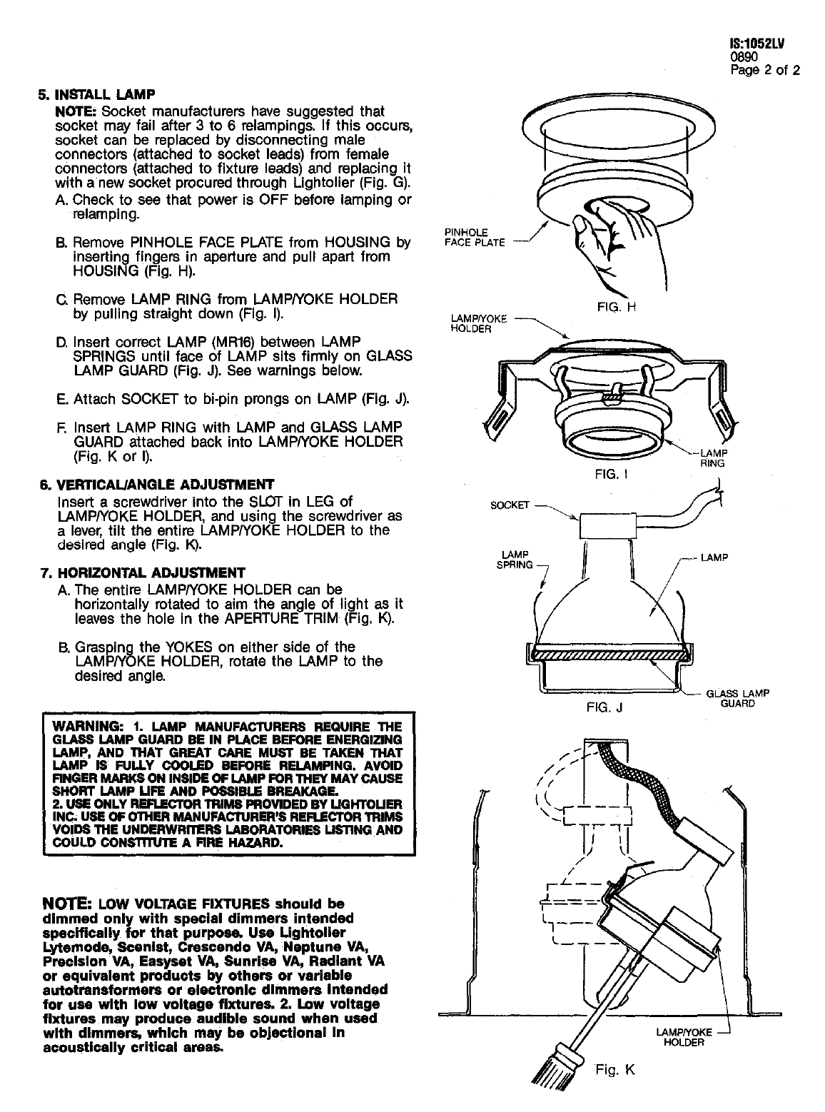
5. INSTALL LAMP
NOTE Socket manufacturers have auggeeted that
eocket may fail after 3to 6relampings. If this occurs,
socket can be replaced by disconnecting male
connectors (attached to socket leads) from female
connectors (attached to fixture leads) and replacing it
with anew eocket procured through Lightolier (Fig. G).
A, Check to see that power is OFF before Iamping or
relamping.
B. Remove PINHOLE FACE PLATE fmm HOUSING by
inserting fingera in aperture and pull apari from
HOUSING (Fig. H).
GRemove IAMP RING fmm LAMPIYOKE HOLDER
by pulling straight down (Fig. l).
D. Insert correct LAMP (MR16) between LAMP
SPRINGS until face of LAMP sits firmly on GLASS
IAMP GUARD (Fig. J). See warninge below.
E. Attach SOCKET to hi-pin pmnga on LAMP (Fig. J).
EInsert LAMP RING with LAMP and GIASS LAMP
GUARD attached back into LAMP/YOKE HOLDER
(Fig. Kor l).
6. VERTfCAL/ANGLE ADJUSTMENT
Insert ascrewdriver into the SLOT in LEG of
lAMPIYOKE HOLDER, and ueing the screwdriver as
alever, tilt the entire IAMPIYOKE HOLDER to the
desired angle (Fig. K).
7. HORIZONTAL ADJLKWMENT
A. The entire LAMP/YOKE HOLDER can be
horizontally rotated to aim the angle of light aa it
Ieavea the hole in the APERTURE TRIM (Fig. K).
B. Graspin the YOKES on either eide of the
8LAMP/Y KE HOLDER, rotate the LAMP to the
deeired angle.
NOIE LOW VOLTAGE FIXTURES should be
dimmed only with special dimmers intended
specifically for that purpoea Use Llghtolier
Lytemode, Scenist, Crescendo VA, Neptune VA
Praolslon VA, Easyaet VA, Sunrise VA, Redlent VA
or equivalent produots by others or verleble
autotraneformera or eleatronlo dlmmera intended
for uae with low voltege fixture% 2. fmw voltage
fixtures may produce audible sound whan ua6d
with dimme~ which may be ob}eotlonsl in
PINHOLE
FACE PLATE
LAMPNOKE
HOLDER
~\
FIG. H
FIG. I
FIG, J
1-
acoustically criticsl erea~
