LigoWave FWBD1401 Broadband Digital Transmission System User Manual
LigoWave LLC Broadband Digital Transmission System Users Manual
UserManual.wiki
>
LigoWave
>
FWBD1401 User Manual
Users Manual
Navigation menu
Upload a User Manual
Namespaces
Wiki Guide
HTML
PDF
Info
Views
User Manual
Discussion / Help
Navigation


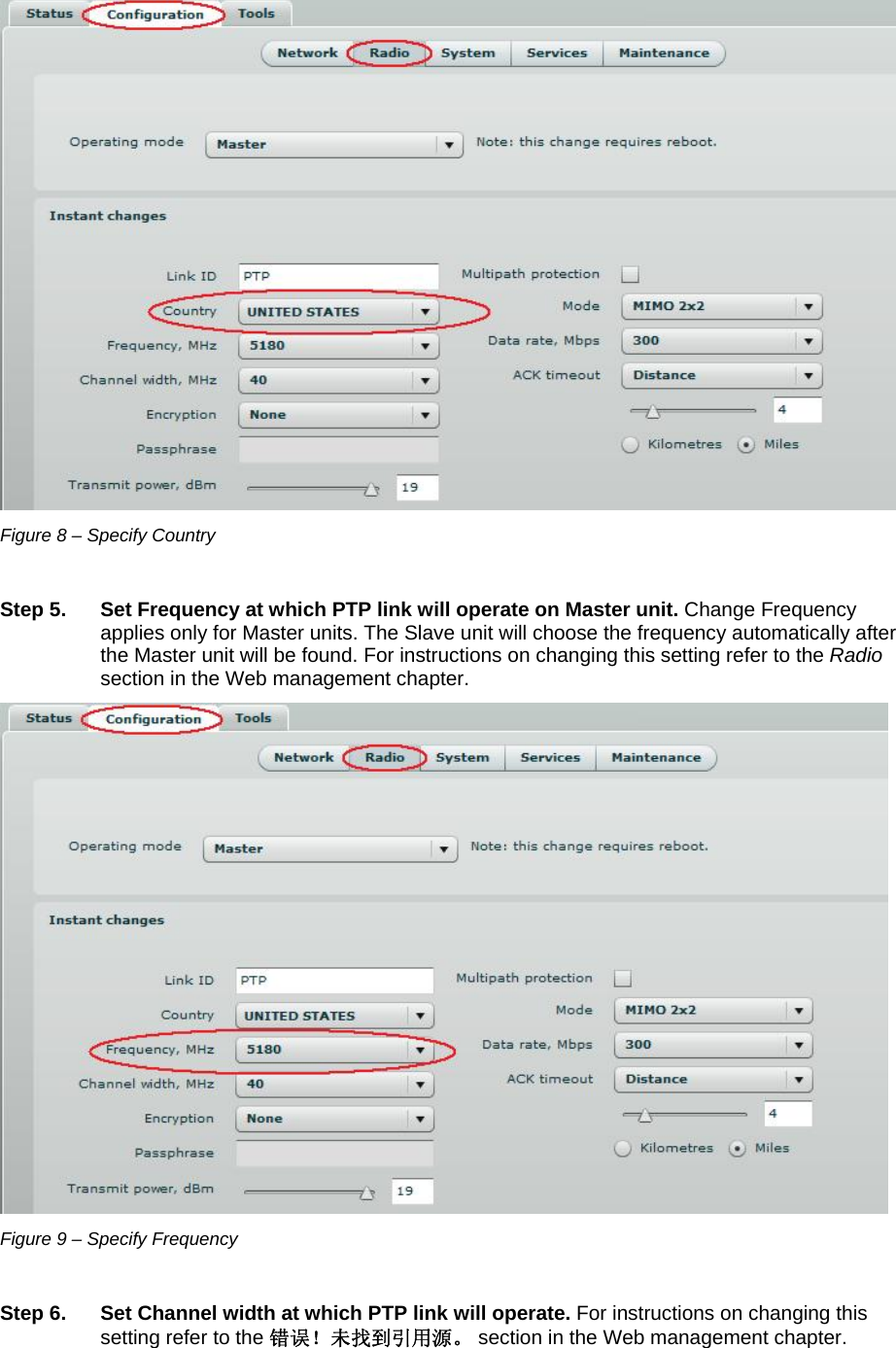

![LigoWave Page 30 Configuration The Configuration page is subdivided into following pages: Network – to set main network configuration for PTP device. Radio – to setup radio settings of the PTP link. System – to setup system date, administrator's access settings, configure system log feature. Services – to setup SNMP, RCMS settings and configure device alerts. Maintenance – for device firmware update, reboot, reset device to factory defaults, troubleshooting file download and to view system log messages. Network The network configuration as described below is required for PTP management purposes. Use the Network menu to setup the network settings of the PTP unit: Figure 35 – Network Settings Method – specify IP configuration mode: Static IP – choose to specify static IP of the device. Dynamic IP – choose to use dynamic IP given by the DHCP server (running DHCP server is required). IP address – specify the device IP address [digit and dots]. When shipped from the factory or reset to factory settings, device defaults to a static IP address of 192.168.2.66. Subnet mask – specify the device subnet mask [digit and dots]. When shipped from the factory or reset to factory settings, the device defaults to a subnet mask of 255.255.255.0. Default gateway – specify the IP address of the device gateway [digit and dots]. When shipped from the factory or reset to factory settings, the device defaults to a gateway IP address of 192.168.2.1. DNS server 1 – specify the IP address of the primary DNS server [digit and dots]. The DNS (Domain Name Service) service translates Internet host names into their IP addresses. DNS server 2 – specify the IP address of the secondary DNS server. Ethernet configuration - configures the Ethernet link speed and the duplex mode of the Ethernet port. Choose "auto" for automatic detection of link speed and duplex mode. Management VLAN ID – specify the management VLAN ID [2-4094].If a management VLAN is enabled, all traffic received by the device must by tagged with the management VLAN ID to access the network. All non-tagged traffic will be dropped, thus reducing the risk of unauthorized access.](https://usermanual.wiki/LigoWave/FWBD1401/User-Guide-1894674-Page-30.png)
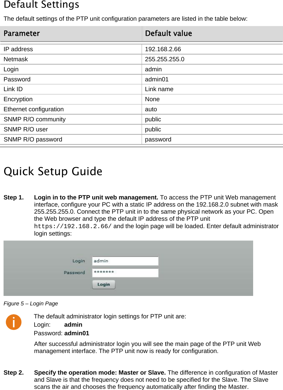
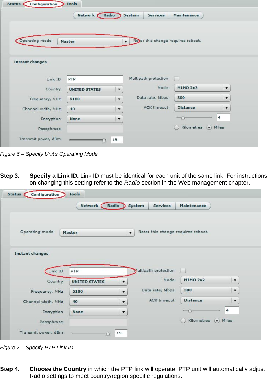
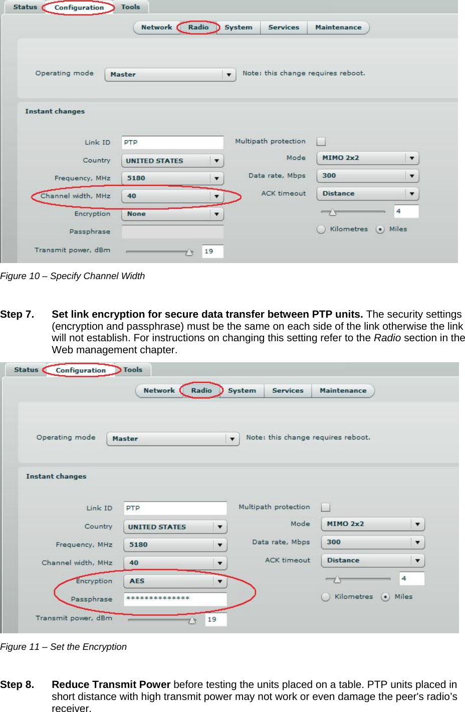
![LigoWave Page 31 Restrict management to – select interfaces on which management access will be restricted. Radio Use the Configuration | Radio menu to set up radio settings for the PTP link: Figure 36 – Radio Settings Operating mode – specify the operating mode of the local device to create PTP link [Master/Slave]. The device mode depends on the network topology. Master – in this mode local device is the controlling PTP link unit. Slave – in this mode local device connects to the Master unit. Instant Changes Applying parameters in the Instant changes section does not require device reboot, therefore making easy parameters adjustment for best performance. Link ID – specify known network name of the remote device to establish a PTP link. Both sides (Master and Slave units) of the link must have the same Link ID name. Country – from drop-down list choose country in which the devices will operate. According to the chosen country the regulatory domain settings may differ. You are not allowed to select radio channels and RF output power values other the permitted values for your country and regulatory domain. Frequency – specify frequency at which the PTP link will be operating. If the device is operating in Slave mode, it will not have the possibility to choose a frequency. The Slave scans the air and connects to the Master automatically.](https://usermanual.wiki/LigoWave/FWBD1401/User-Guide-1894674-Page-31.png)
![LigoWave Page 32 The available Frequencies list varies depending on the selected Country and Channel width. Channel width – choose the channel width in MHz [20/40]. Both sides (Master and Slave) of a link must have the same Link ID, Channel width and Encryption specified. Encryption – select the security level for the PTP link: None – means no security on link. AES – means encryption with passphrase. Passphrase – specify passphrase of the AES security [8-63 characters]. This parameter appears and is mandatory when AES security is chosen. Transmit power – set the radio transmit power at which the device will transmit data. The larger the distance, the higher transmit power is required. To set transmit power level use the slider or enter the value manually. The transmit power level that is actually used is limited to the maximum value allowed by your country's regulatory agency. Multipath protection – if checked the signal will became more robust to signal interference caused by signal echos or reflections. However as the drawback the enabled multipath protection will lead to reduced link capacity. Mode – choose the PTP antenna operating mode: SISO – single input single output. The device will use only one antenna for data transfer. The antenna will be chosen automatically. MIMO – multiple input multiple output. The device will use two antennas for data transfer (two simultaneous streams). In this mode the *link capacity doubles *if compared to SISO mode. Data rate – select the device data transmission rates in Mbps from the drop-down list. ACK Timeout – specify the Acknowledgement timeout either in distance, or in time expression: Distance – specify the distance between PTP units, and ACK timeout will be calculated automatically according the indicated distance in kilometers or myles. Time – specify the ACK timeout in time expression.](https://usermanual.wiki/LigoWave/FWBD1401/User-Guide-1894674-Page-32.png)
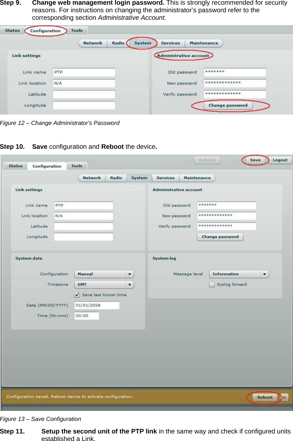
![LigoWave Page 33 System The System page is subdivided into 4 sections: Link settings – to specify PTP link settings. System date – to setup system date and time of the PTP unit. Administrative account – to change administrator's password. System log – to configure logging of the system messages. Link Settings Figure 37 – Link Settings Link name – specify name of the PTP link that is used to identify the unit on the network [maximum 255 ASCII characters]. Link location – describe the location of the PTP unit [maximum 255 ASCII characters]. Longitude – specify the longitude coordinates of the PTP unit [specific decimal format, e.q. 54.869446]. Latitude – specify the latitude coordinates of the PTP unit [specific decimal format, e.q. 23.891058]. Both coordinates helps indicate accurate location of the PTP unit's. System Date Use this section to manage the system time and date on the device automatically, using the Network Time Protocol (NTP), or manually, by setting the time and date on the PTP unit. The NTP (Network Time Protocol) client synchronizes the clock of the device with the defined time server. Choose NTP from the configuration menu, select your location timezone and enter NTP server in order to use the NTP service:](https://usermanual.wiki/LigoWave/FWBD1401/User-Guide-1894674-Page-33.png)
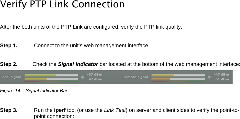
![LigoWave Page 34 Figure 38 – System Date: NTP Configuration Configuration – choose the system clock configuration mode [NTP/Manual]. Timezone – select the timezone. Time zone should be specified as a difference between local time and GMT time. Save last known time – select to recall the timestamp that was saved on last reboot. When NTP is enabled, this option will set system clock to last reboot time if no NTP servers are available. NTP server – specify the trusted NTP server IP or hostname for synchronizing time with [IP address]. To adjust the clock settings manually, choose the configuration mode as Manual and specify the following settings: Figure 39 – System date: Manual Clock Configuration Configuration – choose the system clock configuration mode [NTP/Manual]. Timezone – select the timezone. Time zone should be specified as a difference between local time and GMT time. Save last known time – select to recall the timestamp that was saved on last reboot. Date – specify the new date value in format MM/DD/YYYY. Time – specify the time in format hh:mm. If the device hardware has no internal clock, the configured manual time will be reset to the specified date and time after each device reboot.](https://usermanual.wiki/LigoWave/FWBD1401/User-Guide-1894674-Page-34.png)
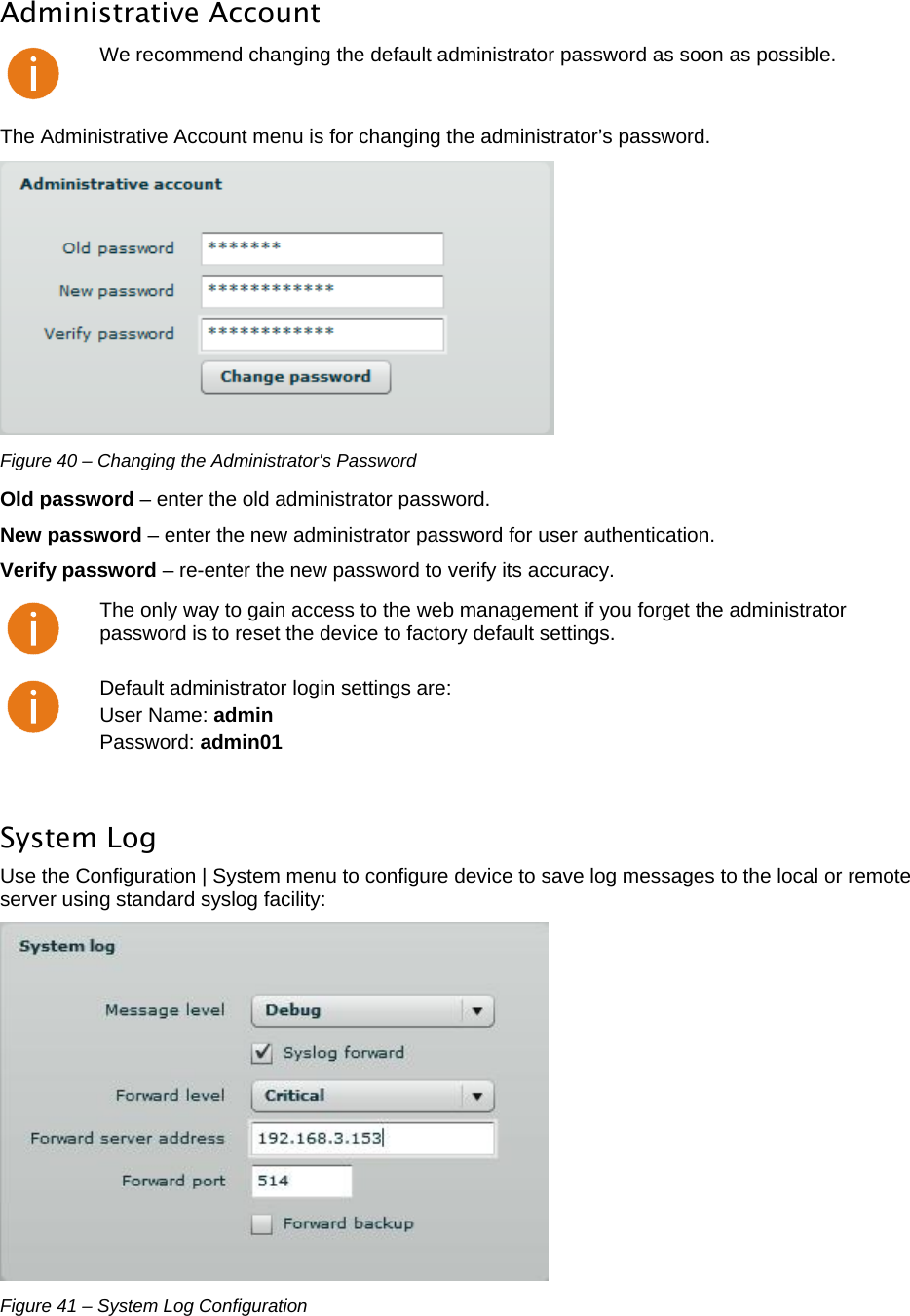
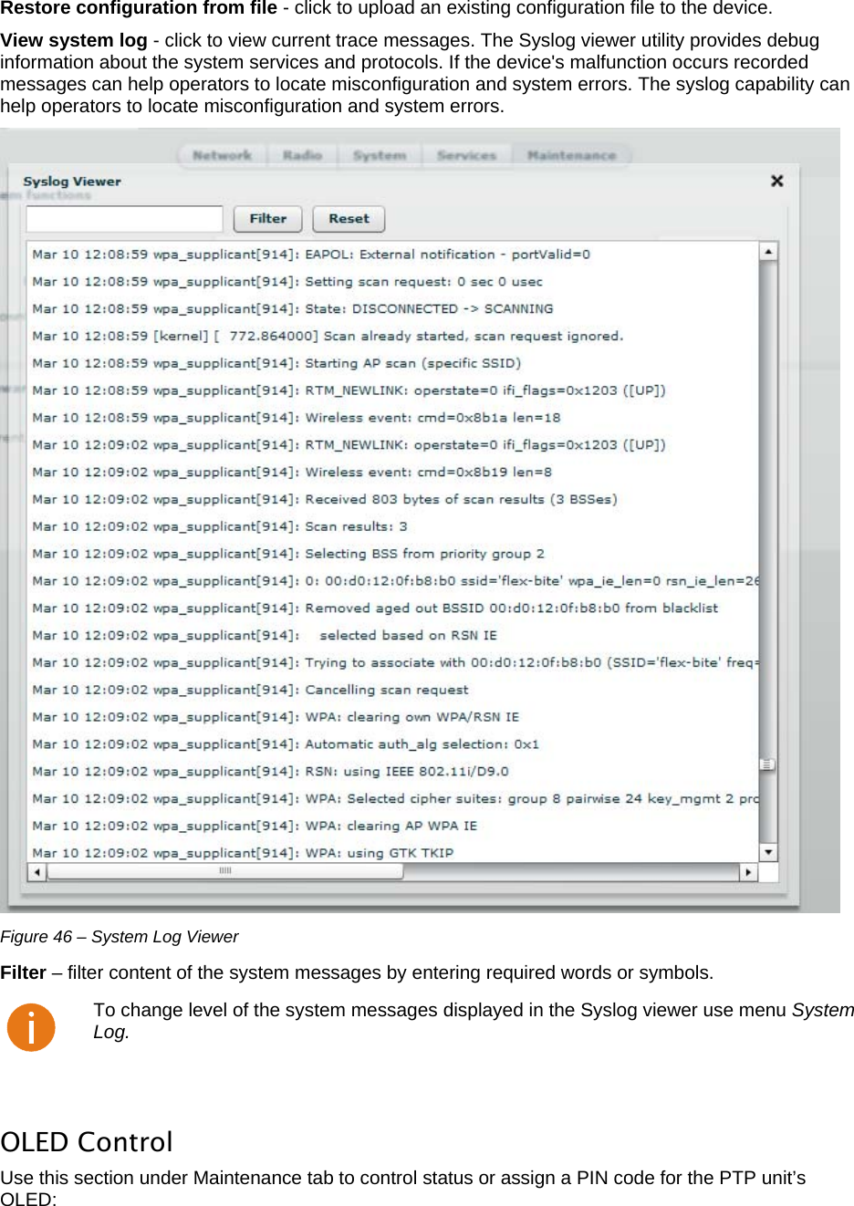
![LigoWave Page 36 Message level – specify system's message tracing level. The level determines the importance of the message and the volume of messages generated by the PTP unitThe levels are in increased importance order [emergency, alert, critical, error, warning, notice, information, debug]. Default: info. The PTP unit can be configured to send system log messages to a remote server: Syslog forward – select to enable remote system logging. Forward server – specify the remote host IP address or hostname where syslog messages will be sent. Forward port – specify the port to which syslog messages will be forwarded [0-65535]. Default: 514. Forward message level – specify the message level that will be send to the remote syslog server. The level determines the importance of the message and the volume of messages generated by the PTP unit. The levels are in order of increasing importance [emergency/alert/critical/error/warning/notice/information/debug]. Default: information. Forward backup – select to enable remote syslog logging backup. Backup server – specify the backup host IP address or hostname where syslog messages will be send to. Backup port – specify the port to which syslog messages will be forwarded [0-65535]. Default: 514. To view logged system messages locally, navigate to the menu Maintenance Services The Services page is divided into 3 sections: SNMP configuration – To enable SNMP and setup SNMP on the PTP unit. RCMS configuration – to enable and setup RCMS agent on the PTP unit. Alerts – to enable and setup system alerts. SNMP Configuration SNMP is the standard protocol that is widely used for remote network management over the Internet. With the SNMP service enabled, the PTP unit can act as SNMP agent. To communicate with SNMP manager you must configure SNMP communities and identifiers on both ends (manager and agent). Figure 42 – SNMP Settings Configuration Enable SNMP – specify the SNMP service status.](https://usermanual.wiki/LigoWave/FWBD1401/User-Guide-1894674-Page-36.png)
![LigoWave Page 37 Name – displays an administratively assigned name. System location – displays the physical location of the PTP unit [string]. R/O community – specify the read-only community name for SNMP version 1 and version 2c [string]. The read-only community allows a manager to read values, but denies any attempt to change values. R/O user – specify the user name for read-only SNMPv3 access [string]. The read-only community allows a manager to read values, but denies any attempt to change values. R/O user password– specify the password for read-only SNMPv3 access [string]. WNMS Configuration Wireless Network Management System (WNMS) is a centralized monitoring and management system for wireless network equipment. The communication between managed devices and the WNMS server is always initiated by an WNMS agent service running on every device. Figure 43 – WNMS Agent Configuration Enable WNMS – select to enable WNMS agent settings. Server/Collector URL – specify the URL of the WNMS server that heartbeat notifications will be sent to. System Alerts The PTP unit is able to send external alerts when there are system errors. The alerts can be sent via SNMP Traps or/and SMTP notifications.](https://usermanual.wiki/LigoWave/FWBD1401/User-Guide-1894674-Page-37.png)
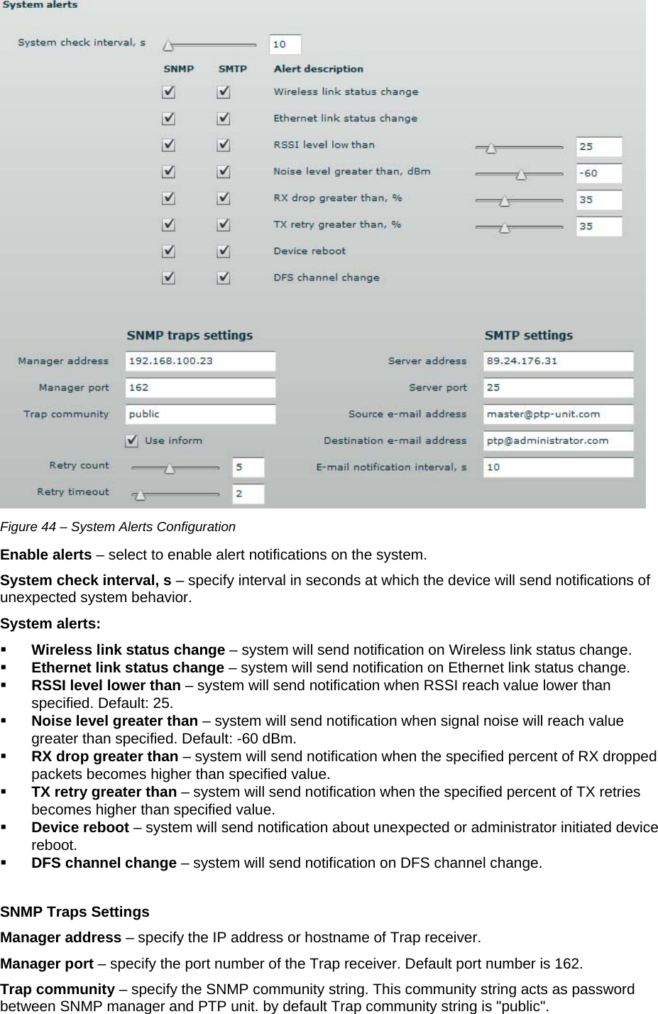
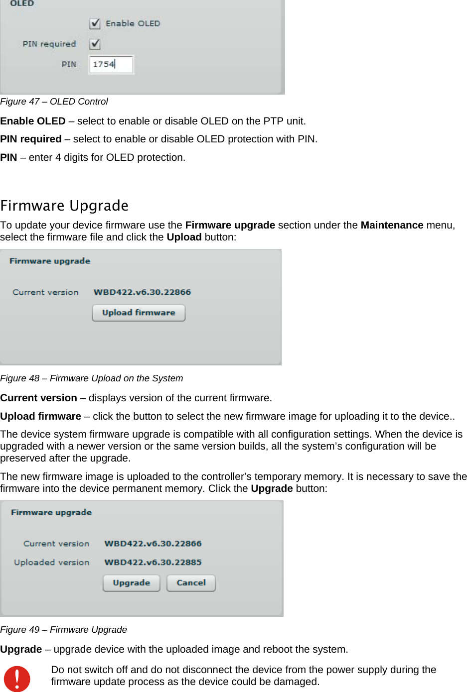
![LigoWave Page 39 Use inform – select to wait for an acknowledgment from SNMP manager that trap was received. Retry count – specifies maximum number of times to resend an inform request [1-10]. Default: 5. Retry timeout – specifies number in seconds to wait for an acknowledgment before resending request [1-10]. Default: 1. SMTP Settings Server address – specify the IP address or hostname of the networked SMTP server. Server port – specify the SMTP Port Number is the port number used by the networked SMTP server. By default the port number is 25. Source e-mail – specify the e-mail address that will be used by the PTP unit. Destination e-mail – specify the e-mail address where the PTP unit will send the alert messages. E-mail notification interval – specify interval in seconds at which the e-mail notification will be sent from the PTP unit [0-86400]. If 0 specified, then device will send an e-mail notification immediately after unexpected system behavior. Maintenance Use Maintenance menu for device firmware update, reboot, reset device to factory defaults, troubleshooting file download, view system log messages and control OLED. System Functions Figure 45 – Main System Functions Reboot device – reboot device with the last saved configuration. Reset device to factory defaults – click to restore unit's factory configuration values. Resetting the device is an irreversible process. Current configuration and the administrator password will be set back to the factory default. Download troubleshooting file – click to download the troubleshooting file. The troubleshooting file contains valuable information about device configuration, routes, log files, command outputs, etc. When using the troubleshooting file, the device quickly gathers troubleshooting information automatically, rather than requiring you to gather each piece of information manually.. This is helpful for submitting problems to the support team. Backup configuration file - click to save the current configuration file. The saved configuration file is useful to restore a configuration in case of a device misconfiguration or to upload a standard configuration to multiple devices without the need to manually configure each device through the web interface..](https://usermanual.wiki/LigoWave/FWBD1401/User-Guide-1894674-Page-39.png)