LigoWave PTP24 Low Power Point to Point Transmitter User Manual Title
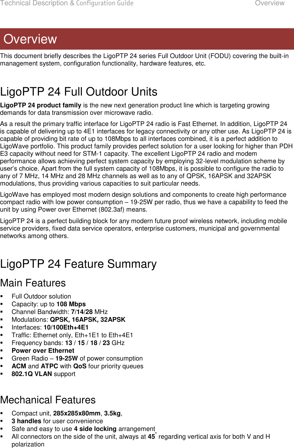
LigoWave LLC Low Power Point to Point Transmitter Title
UserManual.wiki
>
LigoWave
>
PTP24 User Manual
revised users manual
Navigation menu
Upload a User Manual
Namespaces
Wiki Guide
HTML
PDF
Info
Views
User Manual
Discussion / Help
Navigation
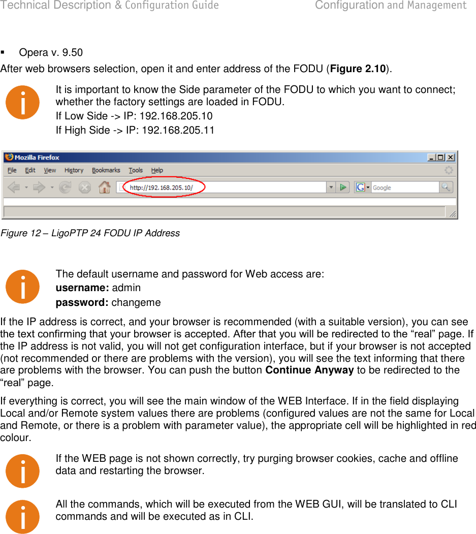
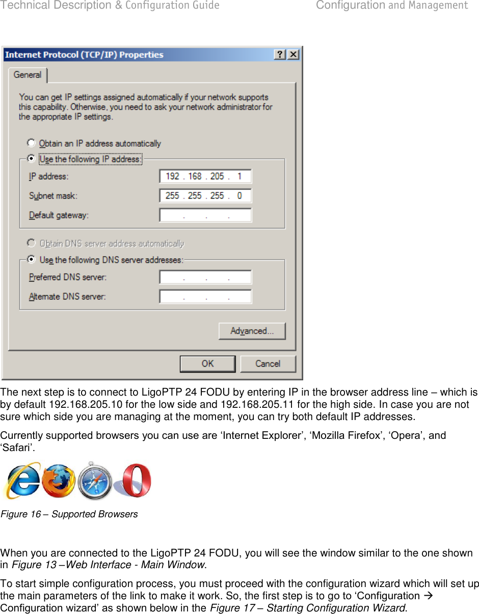
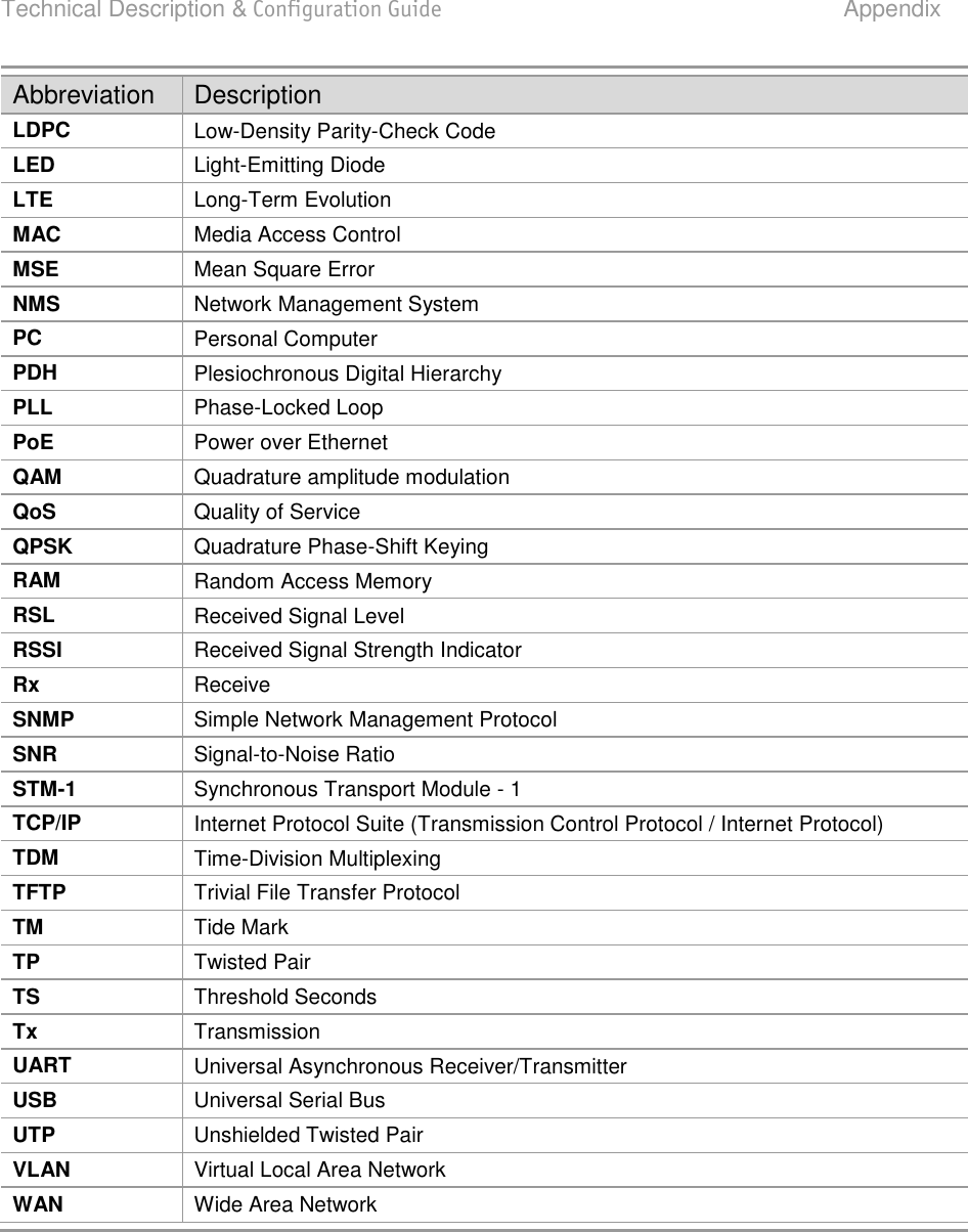
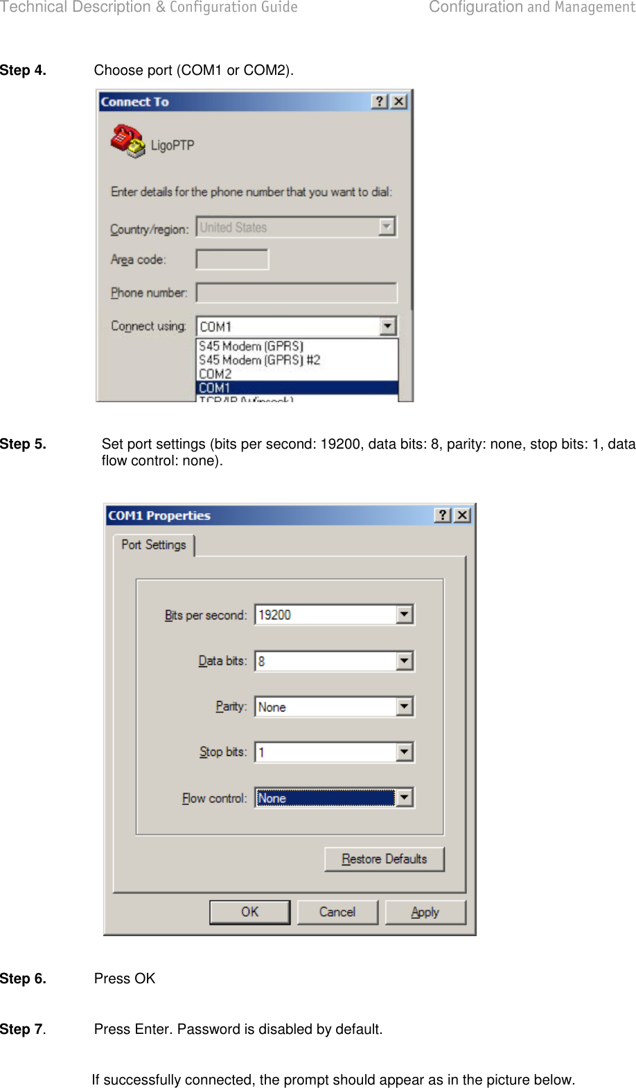
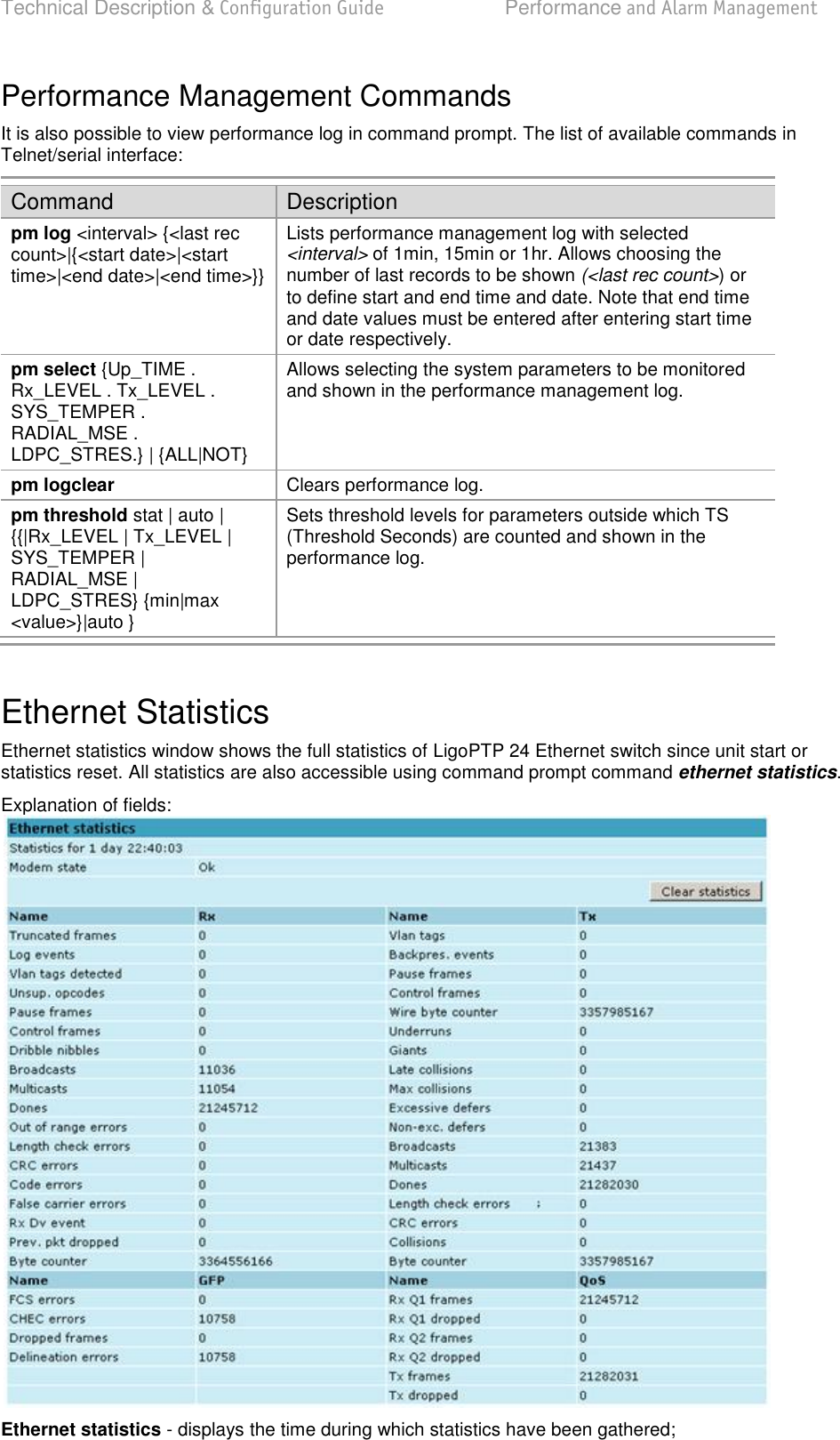
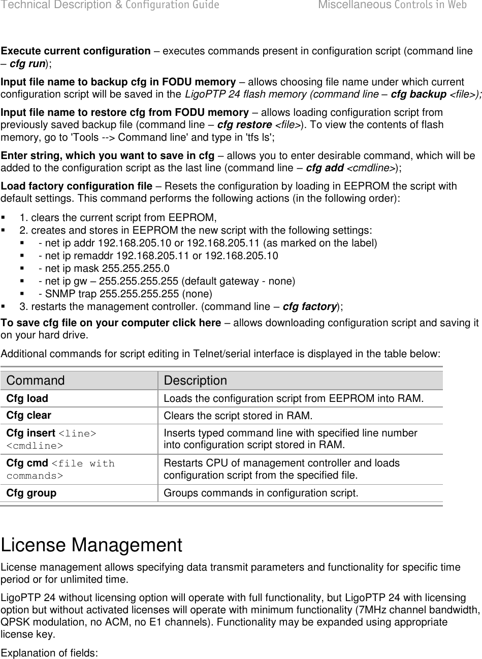
![Technical Description & Configuration Guide Configuration and Management LigoWave Page 27 Figure 22 – STEP 5. Checking settings and executing configuration To verify the settings, we can go to Status or the main screen, which is the first option in the navred fi, everything is set correctly and the link is up. Command Prompt Interface The LigoPTP 24 equipment can be monitored and configured by using command interface described in this chapter. This process is performed by connecting to the Telnet terminal via the Ethernet management port; the Telnet management supports only one client. The command line management interface offers the widest configuration and monitoring functionality. The available commands for Telnet management are found in detailed explanation of Web GUI windows, as well as in tables of additional commands. To end Telnet session press Ctrl+D. Opening the session again, the prompt will appear to enter username and password. For default (factory) usernames and passwords please refer to chapter Configuration File. Syntactic notes for command prompt commands Commands are in bold font. All arguments (variables) are in italic font. Subcommands and keywords are in regular font. Arguments in square brackets ([ ]) are optional but required arguments are in angle brackets (<>). Alternative keywords are grouped in braces ( {} ) and separated by vertical bars ( | ). The usage of each command is displayed if the command followed by tunrecognizable string) is entered, e.g., radio ? The management system is automatically restarted if it freezes. This is performed by the watchdog timer. Restarting of the management system does not affect (interrupt) the E1/Ethernet traffic.](https://usermanual.wiki/LigoWave/PTP24/User-Guide-1302070-Page-27.png)
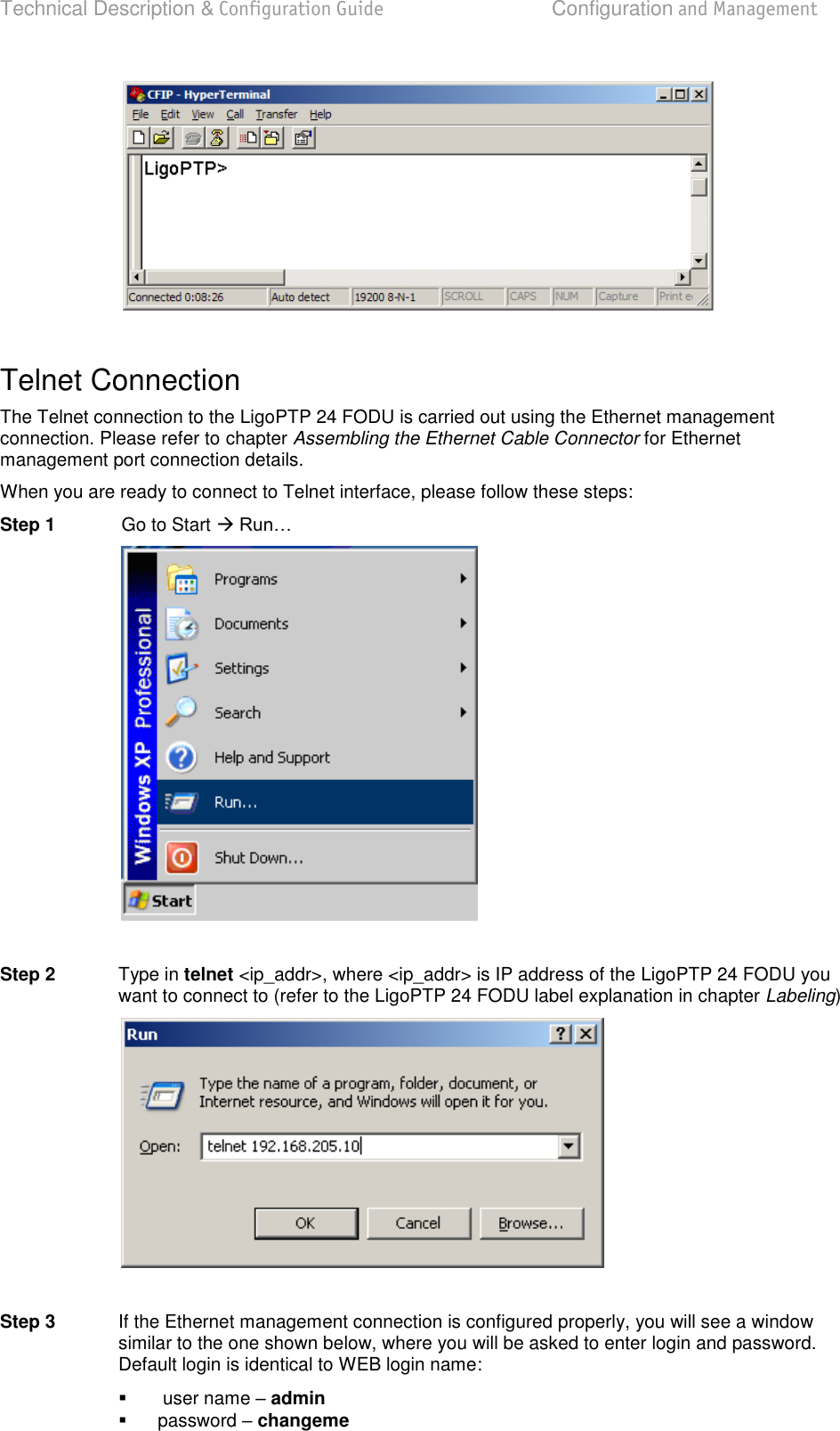
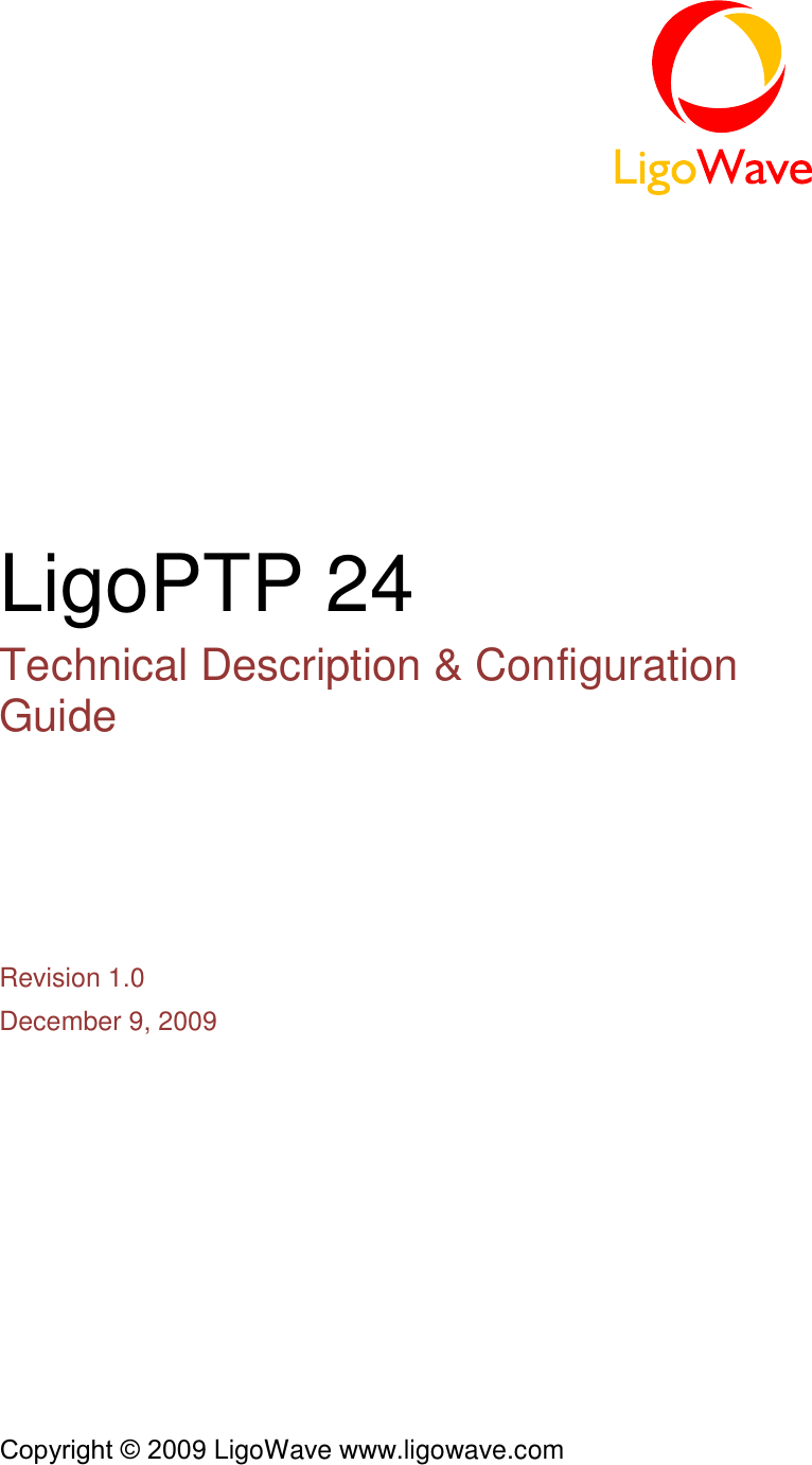
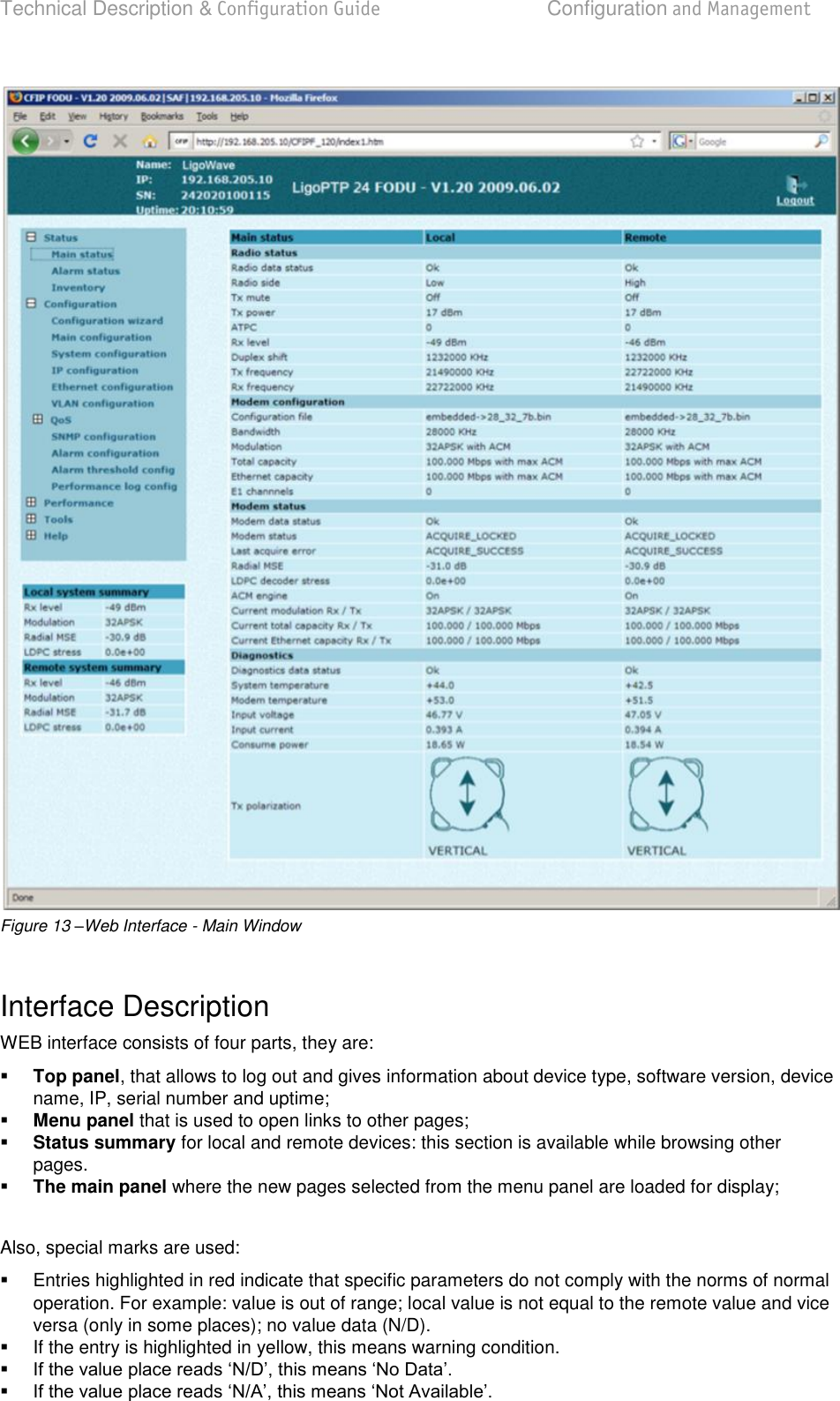
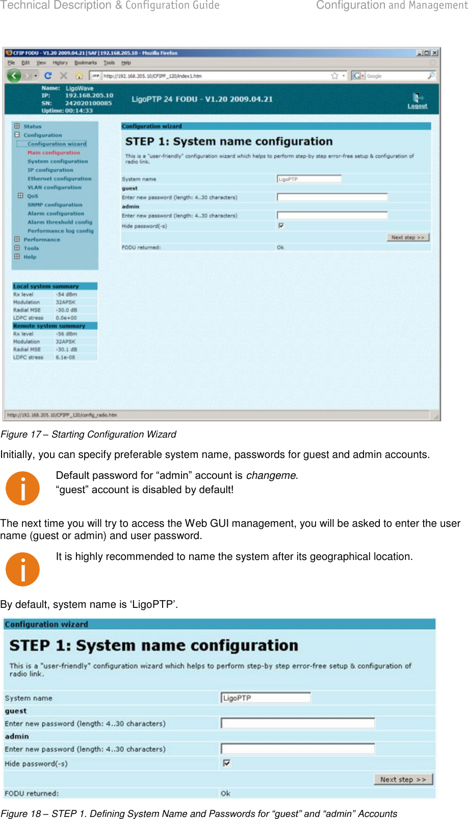
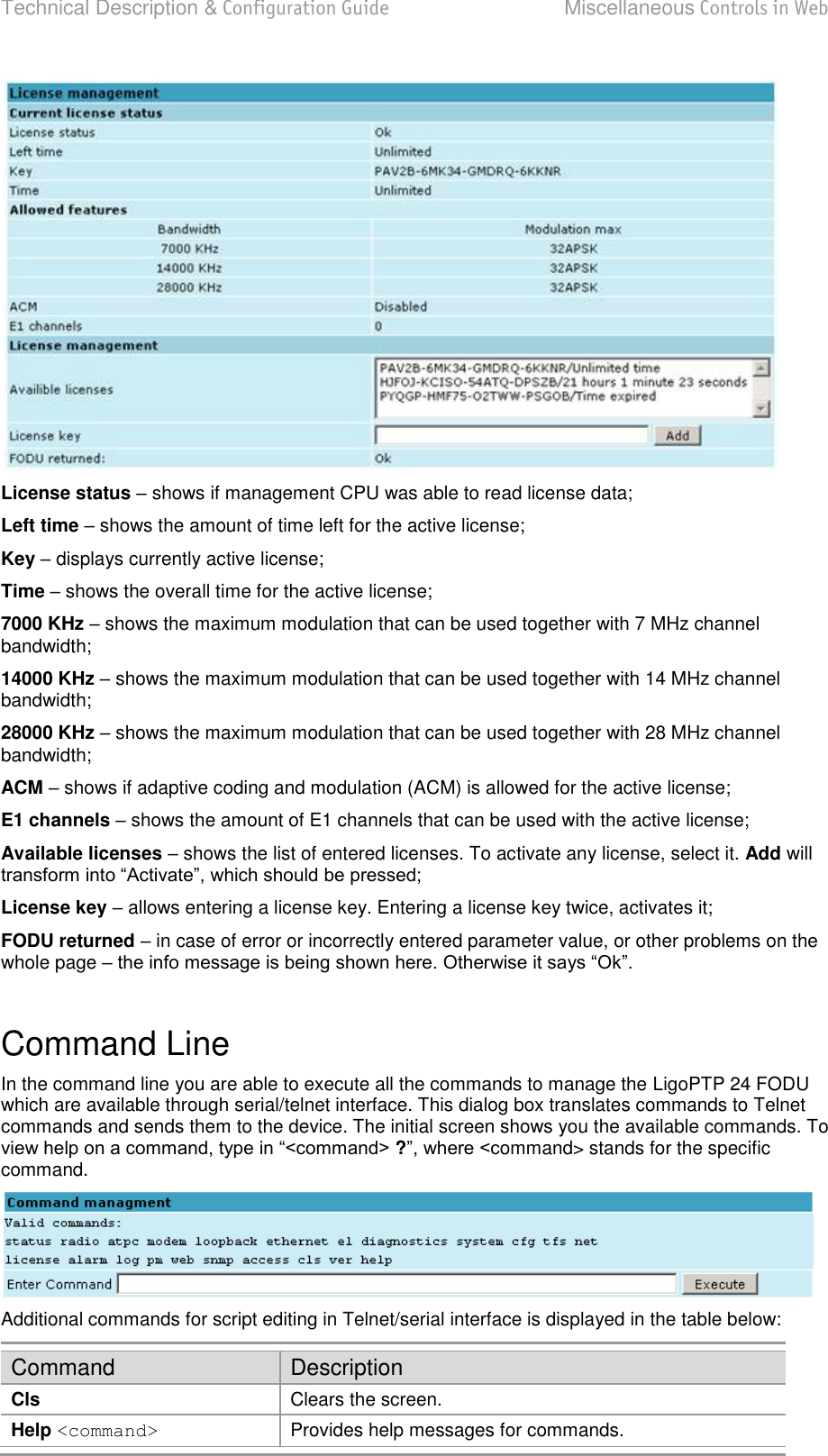
![Technical Description & Configuration Guide Configuration and Management LigoWave Page 31 After you have correctly entered the login and password, you are ready to work with all the available command prompt commands. Initial Configuration with Command Prompt Configuration steps using command prompt are as follows: Step 1. Check the system settings with command status Step 2. Configuration required parameters: Tx power with the command radio txpower [<power dBm>]; Tx frequency with the command radio freq [<freq KHz>]; modem bandwidth <among 7, 14 or 28 MHz values; Before you set above mentioned parameters, you must know what frequency and bandwidth you may use and at what power you may transmit. Modulation with the command modem modulation <QPSK|16APSK|32APSK> [wide] [ACM]; Number of E1 channels with the command e1 set <Number of E1 channels>; Name of LigoPTP 24 FODU with the command system name <name>. Default name is LigoPTP IP address with the command net ip addr <addr>, if it is necessary; IP mask with the command net ip mask <mask> , if it is necessary; IP default gateway with the command net ip gw <gw> , if it is necessary; Remote IP address with the command net ip remaddr <remaddr>, if it is necessary; Step 3. Save settings with the command cfg write; restarting with the command system reset; Step 4. Check the settings made, modem and radio status with the commands status, modem status and radio status respectively.](https://usermanual.wiki/LigoWave/PTP24/User-Guide-1302070-Page-31.png)
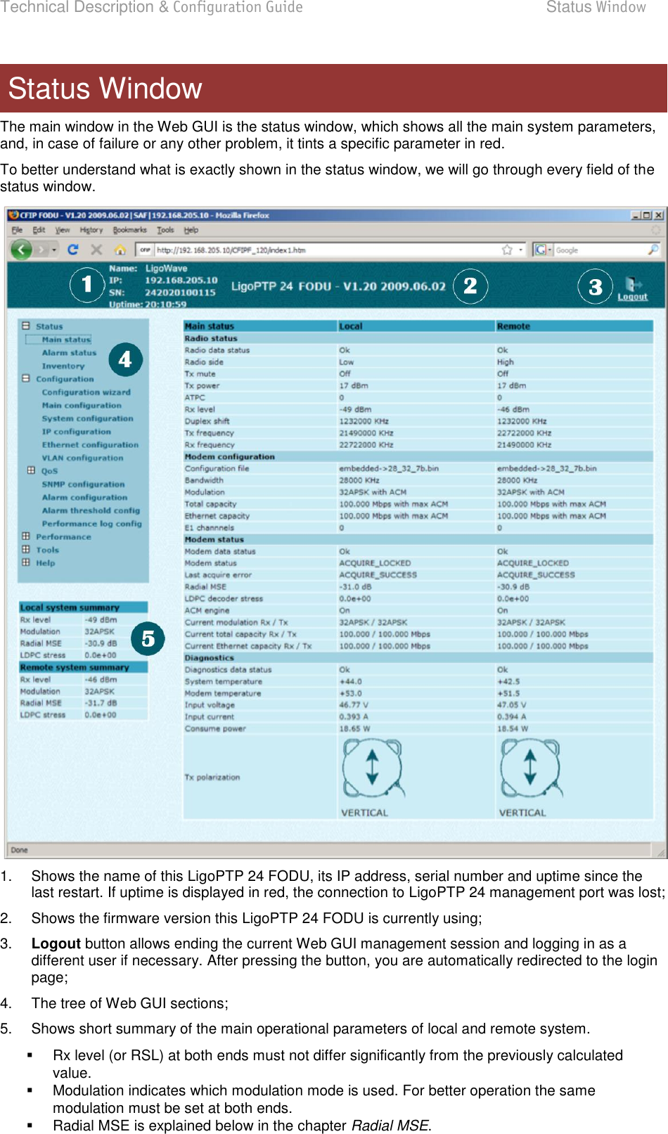
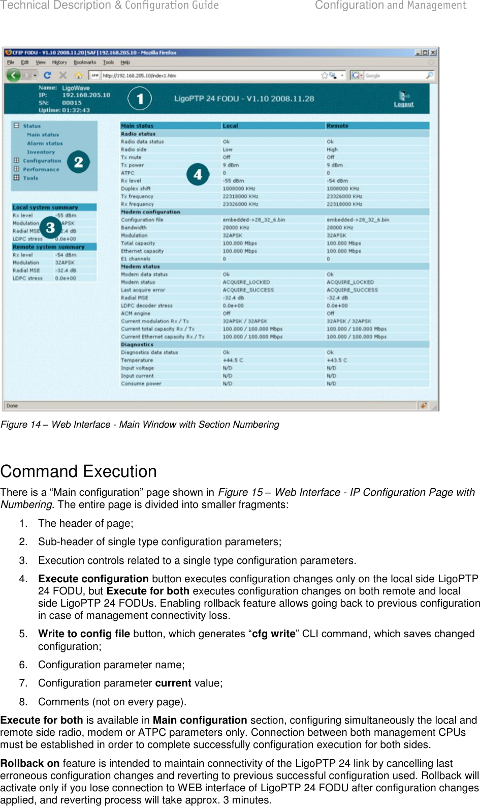
![Technical Description & Configuration Guide Detailed Configuration in Web LigoWave Page 35 Configuration section in Web interface allows customizing your system to suit your specific needs. Main Configuration The main configuration window provides the configuration of most vital system parameters, including the ones in configuration wizard as well as some other important parameters. Below is a short explanation of provided customization fields. Radio Configuration Radio data status shows if management CPU was able to read data from radio; Radio side shows if radio side you are currently viewing is low or high (command line radio side); Tx power allows you to define transmitter power. If the RSL is too high (much higher than normal -50dBm), you might want to lower transmitter power. Too high Rx level (>20 dBm) may even result in synchronization loss. The minimum and maximal values you can choose are dependent on modulation type and LigoPTP 24 model. Maximal and minimal Tx power values are shown in the brackets. (command line - radio txpower [<power dBm>]); Tx frequency (22014000..22582000 KHz) allows you to enter preferable transmitter frequency, hence defining utilized channel (command line - radio txfreq [<freq KHz>]); Rx frequency shows the current receiver utilized frequency (command line - radio freq); Duplex shift shows the duplex shift between the transmitter frequency and receiver frequency (command line - radio duplexshift); Tx mute allows turning transmitter power off. It may be effective when diagnosing on interference existence when transmitter power of one side is off, you should not experience significant RSL on the other side (command line - radio txmute [on|off]); Pressing Execute configuration applies changes made to the corresponding section only for the local side LigoPTP 24 Rollback on is selected, configuration will be reverted in case of erroneous configuration changes applied. Pressing Execute for both applies changes made to the corresponding section both for local and remote side LigoPTP 24 FODUs. Detailed Configuration in Web](https://usermanual.wiki/LigoWave/PTP24/User-Guide-1302070-Page-35.png)
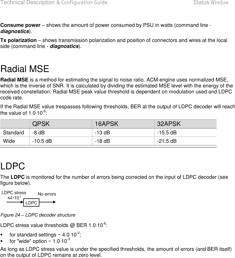
![Technical Description & Configuration Guide Detailed Configuration in Web LigoWave Page 36 ATPC Configuration To configure feature. ATPC update period and ATPC delta are recommended to be left unchanged. It is also possible to change the limit of Tx power correction. Note, that ATPC is mechaATPC, transmitter power (Tx power) must be set to the maximum value. ATPC function allows enabling or disabling ATPC (Automatic Transmit Power Control). By default this feature is disabled (command line atpc [enable|disable]); ATPC update period (1..5) allows defining the period in seconds in which ATPC parameters are being updated. By default the update period is 1 second (command line atpc delay <power change delay time 1..5 sec>); ATPC delta (1 .. 5 dB) allows defining ATPC delta - an increment or decrement in which Tx power is being changed. It is highly unadvisable to change this parameter (command line atpc delta <tx power correction step 1..5 dBm>); Tx power correction displays the amount of transmitter power in decibels ATPC has currently corrected (command line atpc status); Tx power correction limit (-19..-1 dB) allows defining the amount of dB ATPC will be able to correct regarding initial Tx power value (command line atpc limit <tx power correction limit -19..-1 dB>); Remote device status shows if management CPU was able to read data from remote management CPU; Rx (remote) level maximum (-60..-20 dBm) allows defining the maximum Rx level. ATPC Tx power correction will be performed only in case of exceeding this defined maximum Rx level (command line atpc rxmax <rx level max -60..-20 dBm>); Rx (remote) level minimum (-90..-50 dBm) allows defining the minimum Rx level. ATPC Tx power correction will be performed only in case of exceeding this defined maximum Rx level (command line atpc rxmin <rx level min -90..-50 dBm>); Pressing Execute configuration applies changes made to the corresponding section only for the local side LigoPTP 24 FODU. If Rollback on is selected, configuration will be reverted in case of erroneous configuration changes applied. Pressing Execute for both applies changes made to the corresponding section both for local and remote side LigoPTP 24 FODUs. ATPC Algorithm](https://usermanual.wiki/LigoWave/PTP24/User-Guide-1302070-Page-36.png)
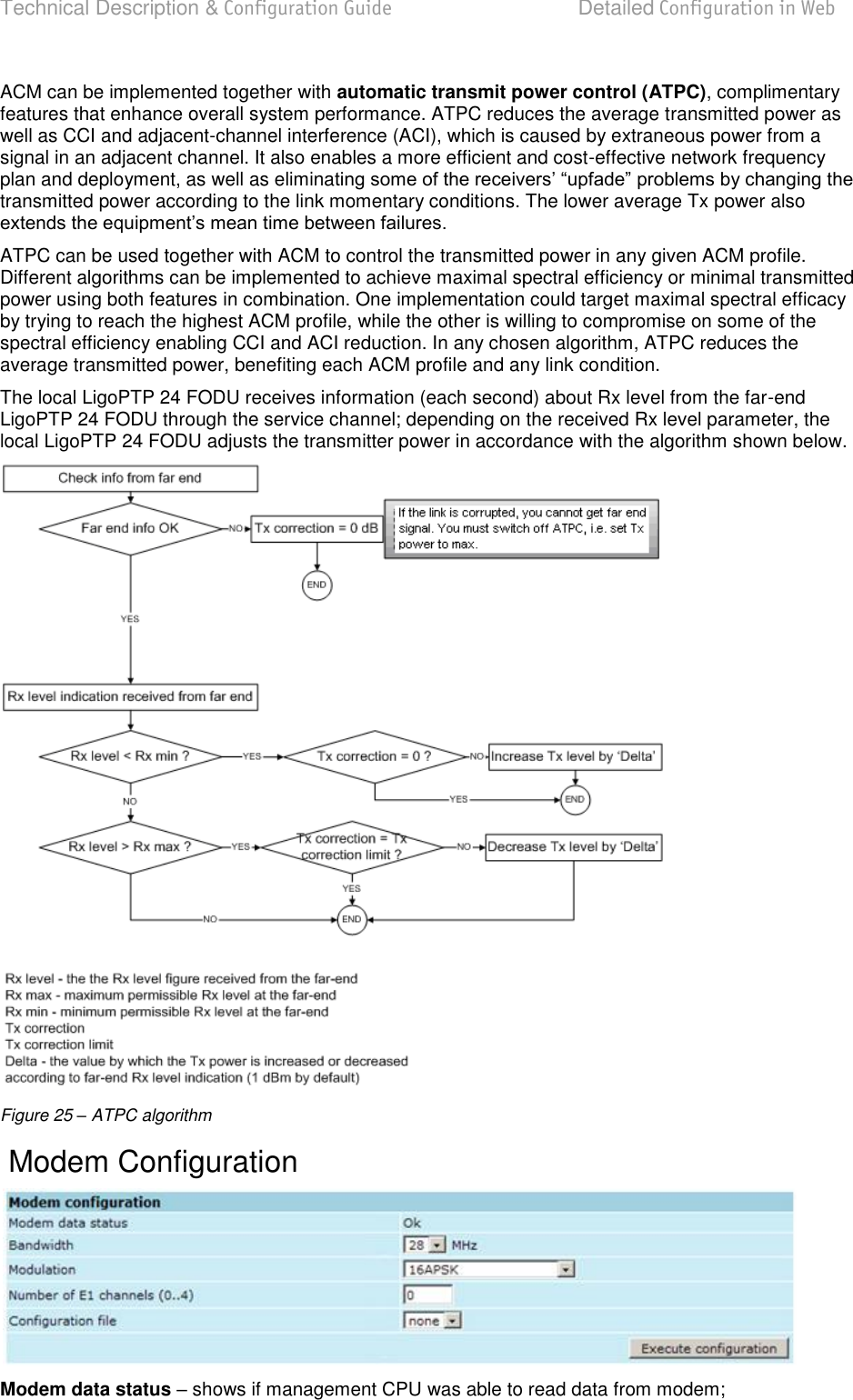
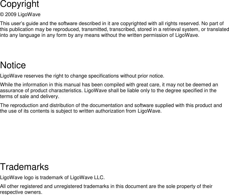
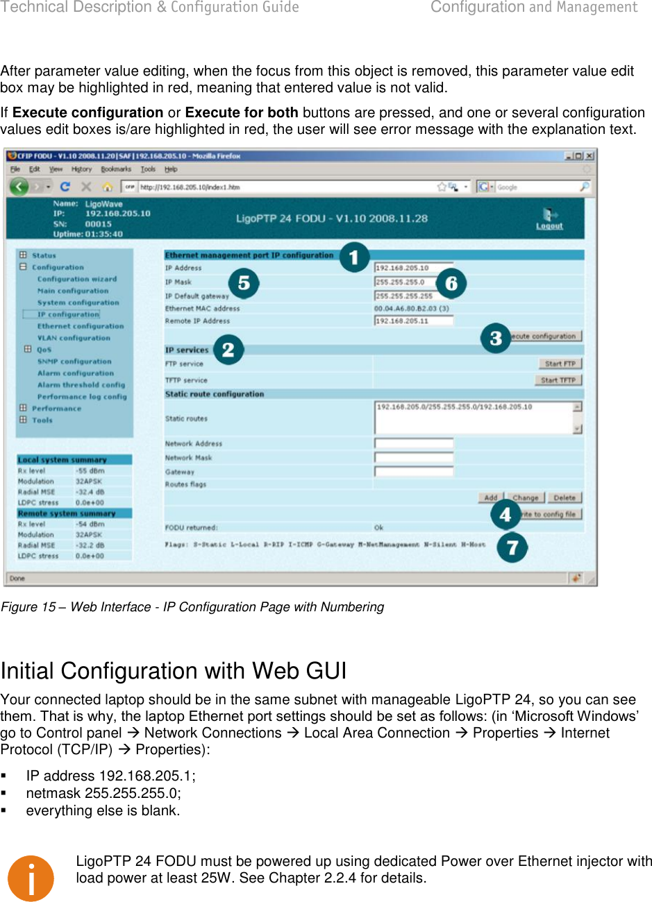
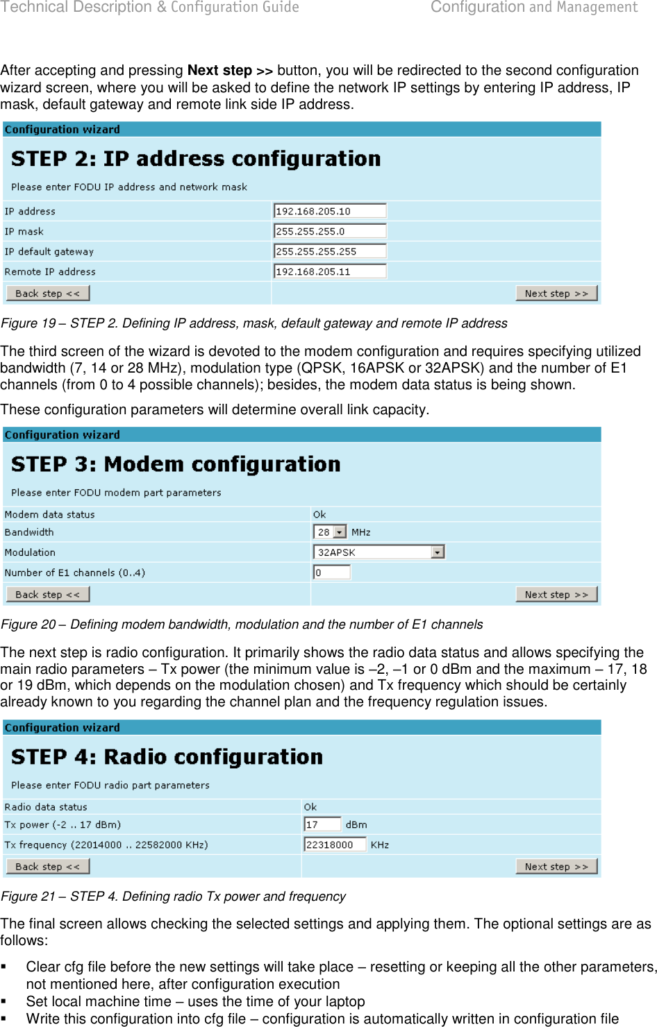
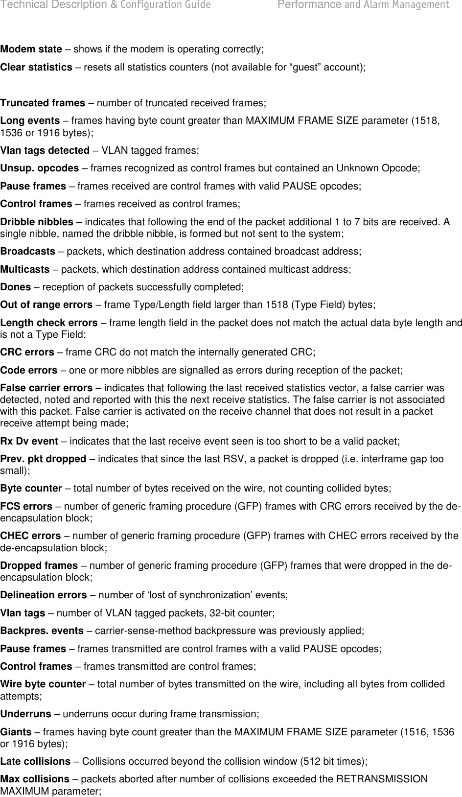
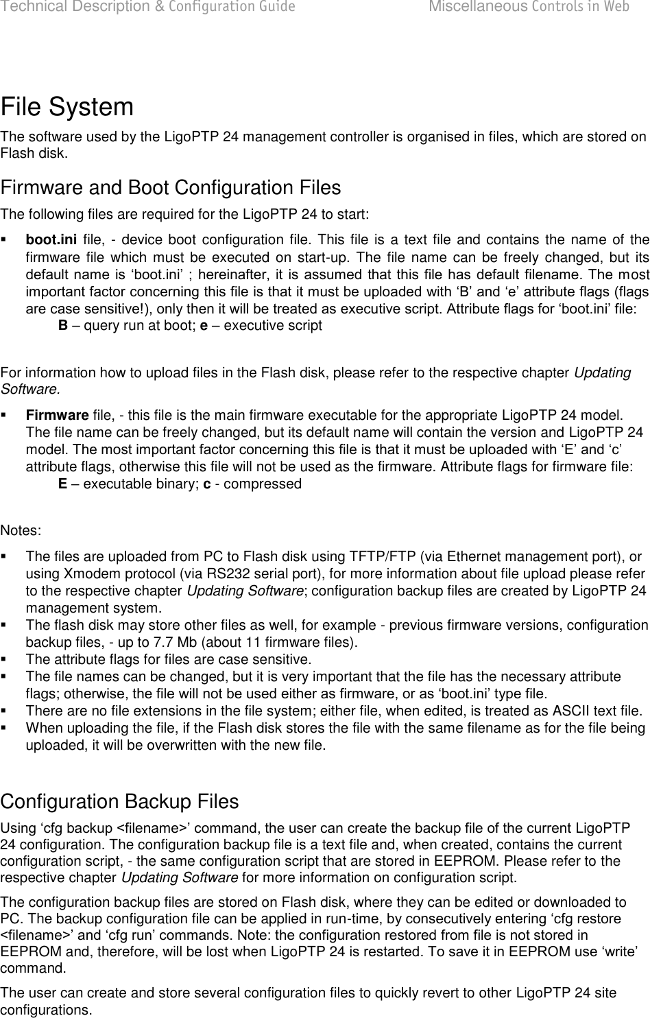
![Technical Description & Configuration Guide Detailed Configuration in Web LigoWave Page 38 Bandwidth allows choosing between 7, 14 and 28 MHz bandwidths available. The default value is 7 MHz. This option is dependent on what bandwidth you have purchased. The wider bandwidth you have, the higher will be the overall link bitrate. The maximum bitrate of 108 Mbps is possible when using 28 MHz bandwidth (command line modem bandwidth 7|14|28); Modulation allows choosing between QPSK, 16APSK and 32APSK modulation. The default value is QPSK. The higher modulation order is, the higher the overall link bitrate, but worse RSL. The maximum bitrate of 108 Mbps is possible when using 32APSK modulation (command line modem modulation QPSK|16APSK|32APSK [wide] [ACM]). See below the explanation for Adaptive Coding and Modulation and wide options; Number of E1 channels (0..4) allows choosing preferable number of E1 channels to be used. When the total capacity is over 100Mbps, number of E1 channels does not influence the total Ethernet capacity (100Mbps), otherwise Ethernet capacity is <total capacity> - <number of E1 channels>*2,048 [Mbps]. By default E1 channels are turned off (command line e1 set <Number of E1 channels>); Configuration file allows you to choose optional modem configuration file. This option is for specific requirements that are not included in default set of configuration options (command line modem configuration show|<file>|embedded); Pressing Execute configuration applies changes made to the corresponding section only for the local side LigoPTP 24 FODU. If Rollback on is selected, configuration will be reverted in case of erroneous configuration changes applied. Pressing Execute for both applies changes made to the corresponding section both for local and remote side LigoPTP 24 FODUs. Adaptive code and modulation (ACM) technology allows operators to achieve high-capacity data transmission over microwave links and improve the link utilization. This reduces both operational and capital expenditures for maintaining high-capacity links. ACM can maintain the highest link spectral efficiency possible at any given time in any link condition. In traditional voice-dominated wireless backhaul transmission networks, service availability levels of 99.995% are the norm. However, newer services such as Internet browsing, video streaming and video conferencing can operate at more relaxed availability levels. With use of QoS prioritizing ACM can allocate the required availability based on the priority. As a result, high-priority services such as voice enjoy 99.995% availability, while low-priority services like video streaming are allocated lower priorities. Use of QoS prioritizing defines which services should be transmitted under any link condition and which services should be adapted whenever the link condition is degraded and the link payload is decreased. For example, when bad weather has decreased the channel capacity of a link, ACM maintains high-priority services such as E1 channels with full bandwidth capacity while adapting the bandwidth capacity of low- and mid-priority services such as Internet browsing (see figure below). Figure 26 – ACM bandwidth capacity adaptation](https://usermanual.wiki/LigoWave/PTP24/User-Guide-1302070-Page-38.png)
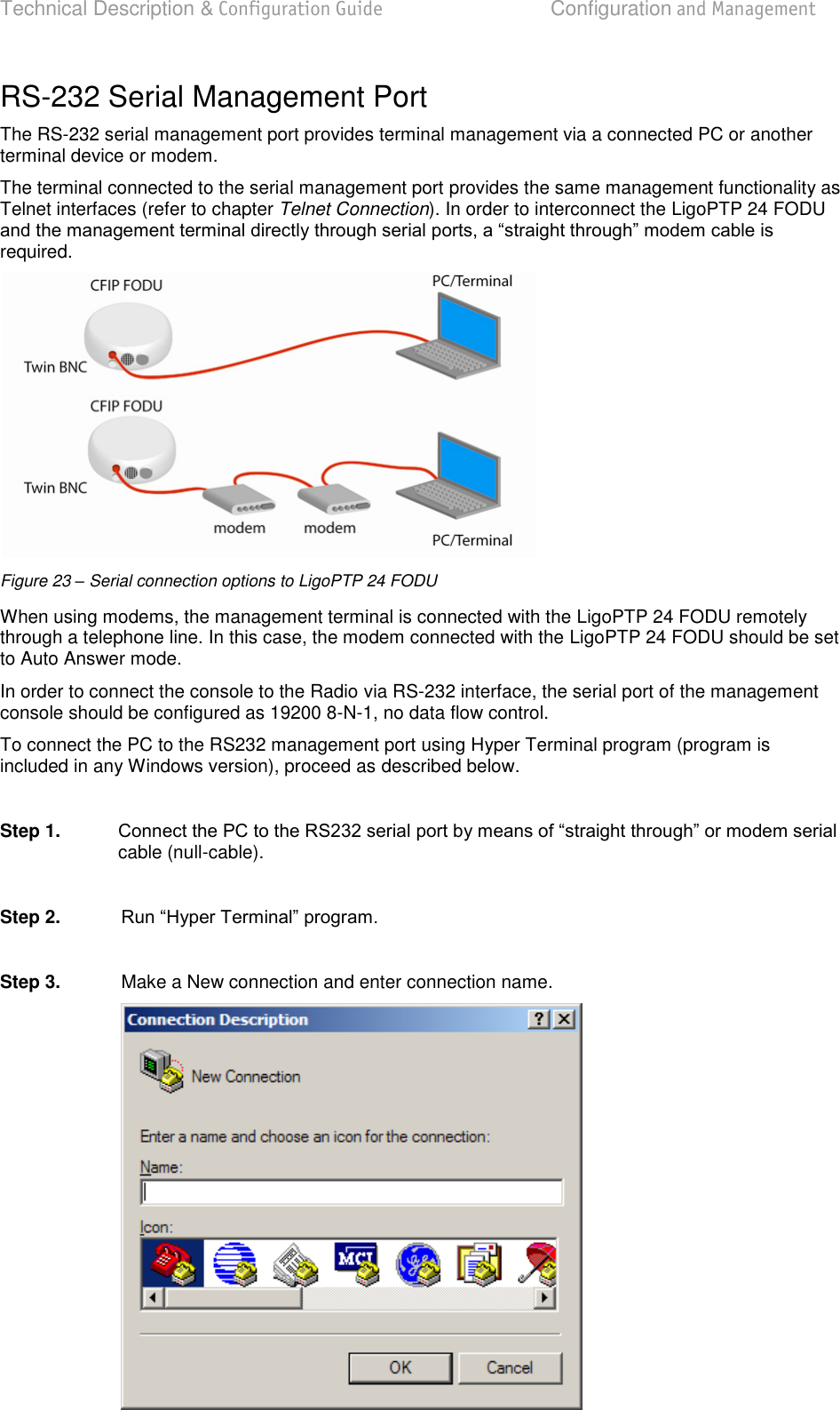
![Technical Description & Configuration Guide Detailed Configuration in Web LigoWave Page 40 In comparison similar system using 32QAM and providing similar capacity would provide only 99,981% of availability. Besides, lack of ACM would not provide higher availability. You would have to decrease the distance, decrease modulation or increase antenna sizes to achieve 99,995% availability for the given link. This example demonstrates how the new technology, based on an ACM mechanism, can play a key role in the development of cost-effective next-generation wireless access networks, by taking advantage of traffic evolution from synchronous TDM traffic to packet IP-based traffic. The wide option allows increasing overall capacity of the link in terms of deteriorating RSL sensitivity threshold. Note, that using 32APSK with total capacity of 100Mbps, LigoPTP 24 automatically uses "better sensitivity" mode, but incrementally enabling E1 channels, LigoPTP 24 adapts it's forward error correction, till the maximum 108Mbps capacity (100Mbps Ethernet + 4E1) is enabled and LigoPTP 24 operates in "wide" mode. For more details refer to table in chapter Cable Requirements. Loopback Configuration Loopback tests are accessible using local or remote management methods. For safety purposes all loopbacks (local and remote) can be set on a fixed time interval only. If no time interval is specified, the default value is 60 seconds (1 minute). Figure 28 – Loopback Modes E1 loopback mode loops signal back to local end in bounds of E1 interface. E1 loopback mode must be set on the particular channel you are wishing to test. If no E1 channels are selected, E1 loopback mode is not available; NEAR loopback mode loops signal back to local end after the modem; IF loopback mode loops signal back to local end by linking intermediate frequencies. Loopback allows choosing loopback mode and its activity time in seconds (command line loopback) {status | none | if | modem | e1{1|2|3|4}} [<time>]); Pressing Execute configuration applies changes made to the corresponding section only for the local side LigoPTP 24 FODU. If Rollback on is selected, configuration will be reverted in case of erroneous configuration changes applied. Write to config file writes to configuration file all the changes made on the whole page (command line cfg write); FODU returned - in case of error or incorrectly entered parameter value, or other problems on the whole page Additional radio and modem configuration commands in Telnet/serial interface is provided in the table below:](https://usermanual.wiki/LigoWave/PTP24/User-Guide-1302070-Page-40.png)
![Technical Description & Configuration Guide Detailed Configuration in Web LigoWave Page 41 Command Description modem status Shows all the modem parameters. modem configuration show Displays current configuration file. modem configuration <file> Uses separate configuration file. modem configuration embedded Switches back to the embedded configuration last used. modem configuration embedded Switches back to the embedded configuration last used. modem factory Resets modem settings to factory defaults. modem ipremote [on|off] Allows enabling manual remote IP specifying. By default remote IP is being obtained automatically. radio factory [max] Resets radio settings to factory defaults. By default Tx to the maximum value after restart. Additional loopback commands in Telnet/serial interface is provided in the table below: Command Description Loopback status Displays status of loopback mode. Loopback {status|none|if |modem|e1{1|2|3|4}}[<time>] Sets the specified loopback mode. System Configuration The system configuration window provides the configuration of web access, telnet and FTP interfaces; allows changing system name, web data refresh time and system time. Explanation of customization fields: User Configuration guest Enter new password (length: 4..30 characters) password and enabling the account. By default guest account is disabled. Maximal length of the password cannot exceed 30 symbols. Guest account has only monitoring privileges. The following Web GUI sections are available:](https://usermanual.wiki/LigoWave/PTP24/User-Guide-1302070-Page-41.png)
![Technical Description & Configuration Guide Detailed Configuration in Web LigoWave Page 42 admin Enter new password (length: 4..30 characters) account password. Maximal length of the user name cannot exceed 30 symbols. By default password LigoPTP 24 configuration process. Hide password(-s) Hides typed in password. Unchecking this option will display typed in password in plaintext. Pressing Execute configuration applies changes made to the corresponding section only for the local side LigoPTP 24 FODU. If Rollback on is selected, configuration will be reverted in case of erroneous configuration changes applied. More detailed status controls are available in command prompt, which include additional user management commands in Telnet/serial interface: Command Description access login <name> <password> Logs on as a user specified by <name> and <password>. access logout Logs current user out. access set <guest|admin> <password> [plaintext] Allows specifying a new password for a specific account save the password in plaintext in configuration script without encrypting it (by default saved passwords in configuration file are encrypted). access show Shows user name and password of a user currently logged on. access list Shows the list of usernames and passwords the current Names Configuration FODU name (Max length: 17 characters) allows entering preferable system name. It is recommended to name the system after its geographic location. Maximum length of the user name cannot exceed 17 symbols. Default name is LigoPTP (command line system name <name>);](https://usermanual.wiki/LigoWave/PTP24/User-Guide-1302070-Page-42.png)
![Technical Description & Configuration Guide Detailed Configuration in Web LigoWave Page 43 Pressing Execute configuration applies changes made to the corresponding section only for the local side LigoPTP 24 FODU. If Rollback on is selected, configuration will be reverted in case of erroneous configuration changes applied. Other Configuration Web refresh (2 .. 600 sec) allows specifying time interval of Web data refreshing. The default value is 5 seconds. You can choose between 2 and 600 seconds (10 minutes) (command line web refresh <web refresh time>); Time (Usage: YY-MM-DD HH:mm:ss) allows changing system date and time manually by entering date and time in specific syntax. Set local machine time button forces system to use the time set on your PC or laptop, from which you are connected to the Web interface (command line system time [yyyy-mm-dd hh:mm:ss]); Pressing Execute configuration applies changes made to the corresponding section only for the local side LigoPTP 24 FODU. If Rollback on” is selected, configuration will be reverted in case of erroneous configuration changes applied. Write to config file writes to configuration file all the changes made on the whole page (command line cfg write); Immediate CPU restart restarts LigoPTP 24 FODU you are connected to ((command line system reset); Note that after restarting the LigoPTP 24 will use only those settings, which are written to the configuration script. Other settings will be set to default values Additional system commands of the Telnet/serial interface is provided in the table below: Command Description System status Displays the name of the device and its uptime. System inventory [sho ] Displays the LigoPTP 24 FODU product code, serial number and additional information. System aliases [list|all|basic|off|add|remove|clear] list shows the alias list and whether the aliases are going to be used. The user can choose whether to see all -in aliases - all all the aliases will be used; basic only basic (built-in, hidden and user) aliases will be used; off no aliases will be used; add if two arguments are given, creates an alias of the second argument, named as the first argument. If one argument given, alias command tries and loads the aliases from a file specified by the argument; remove removes the alias specified by the argument; clear removes all the user aliases. System commands [show|help] show displays all available commands; help displays available help messages for all commands.](https://usermanual.wiki/LigoWave/PTP24/User-Guide-1302070-Page-43.png)
![Technical Description & Configuration Guide Detailed Configuration in Web LigoWave Page 44 Command Description System reset [cold] Restarts CPU of the management controller. Resets all management counters. cold Restarts modem as well. Ver Displays hardware and software version of FODU, as well as built date. Upgrade Software Choose file allows choosing location of software upgrade file stored on your hard disk. Software upgrade file must have *.elf.ezip extension; FODU returned in case of error or incorrectly entered parameter value, or other problems on the whole page IP Configuration Window The IP configuration window provides configuration of the Ethernet management port addressing, IP services and routes. Settings listed here are essential for building a network or other specific traffic purposes. Explanation of customization fields: Ethernet Management Port IP Configuration IP Address allows specifying IP address of LigoPTP 24 FODU you are currently logged in. Default IP address is 192.168.205.10 or 192.168.205.11 depending on which side the specific LigoPTP 24 FODU is low side has 192.168.205.10 IP address and high side 192.168.205.11 (command line net ip addr <addr>); Note that LigoPTP 24 IP addresses need to be in the same subnet. IP Mask allows specifying IP mask of LigoPTP 24 FODU you are currently logged in. Default IP mask is 255.255.255.0, and it should not be changed unless you are owning network with huge amount of hops (command line net ip mask <mask>); IP Default gateway allows specifying gateway of LigoPTP 24 FODU you are currently logged in. Default gateway is 255.255.255.255 which means that there is no gateway specified (command line net ip gw <gw>); Ethernet MAC address shows the MAC address of LigoPTP 24 FODU you are currently logged in (command line net mac); Remote IP Address shows IP address of remote (far-end) LigoPTP 24 FODU to ensure communication between link sides (command line net ip remaddr <remaddr>);](https://usermanual.wiki/LigoWave/PTP24/User-Guide-1302070-Page-44.png)
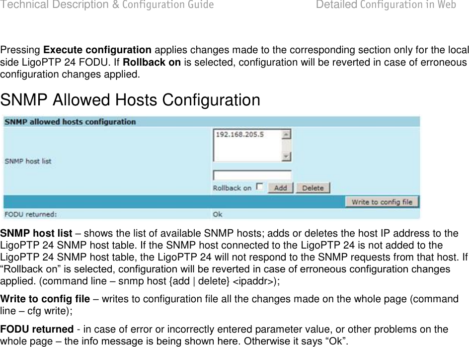
![Technical Description & Configuration Guide Detailed Configuration in Web LigoWave Page 45 Pressing Execute configuration applies changes made to the corresponding section only for the local side LigoPTP 24 FODU. If Rollback on is selected, configuration will be reverted in case of erroneous configuration changes applied. IP Services FTP service – starts FTP service for file access and software update of your LigoPTP 24 FODU. By default FTP service is not running (command line net start ftp); TFTP service – starts TFTP service for file transfer between both LigoPTP 24 FODU link sides. By default TFTP service is not running (command line net start tftp). Static Route Configuration Do not make any changes to default route; otherwise, management connection to LigoPTP 24 will be lost. Static routes shows the list of existing static routes, as well as allows you to choose specific route you are willing to change or delete. By default there is one route which depends on earlier entered IP settings (command line net route); Network address allows specifying network address for the route changing/adding (command line net route add|delete <dest addr> [MASK <mask>] <gateway>); Network mask - allows specifying network mask for changing/adding the route (command line net route add|delete <dest addr> [MASK <mask>] <gateway>); Gateway - allows specifying gateway for the route changing/adding (command line net route add|delete <dest addr> [MASK <mask>] <gateway>); After entering addresses or selecting a specific route, buttons Add, Change and Delete allow you to modify LigoPTP 24 FODU routes. If Rollback on is selected, configuration will be reverted in case of erroneous configuration changes applied. Write to config file writes to configuration file all the changes made on the whole page (command line cfg write); FODU returned - in case of error or incorrectly entered parameter value, or other problems on the whole page Additional network configuration commands in Telnet/serial interface: Command Description Net ping <ip> This command is for troubleshooting purposes to verify the service channel connectivity, - it sends a special packet to the specified address and then waits for a reply.](https://usermanual.wiki/LigoWave/PTP24/User-Guide-1302070-Page-45.png)
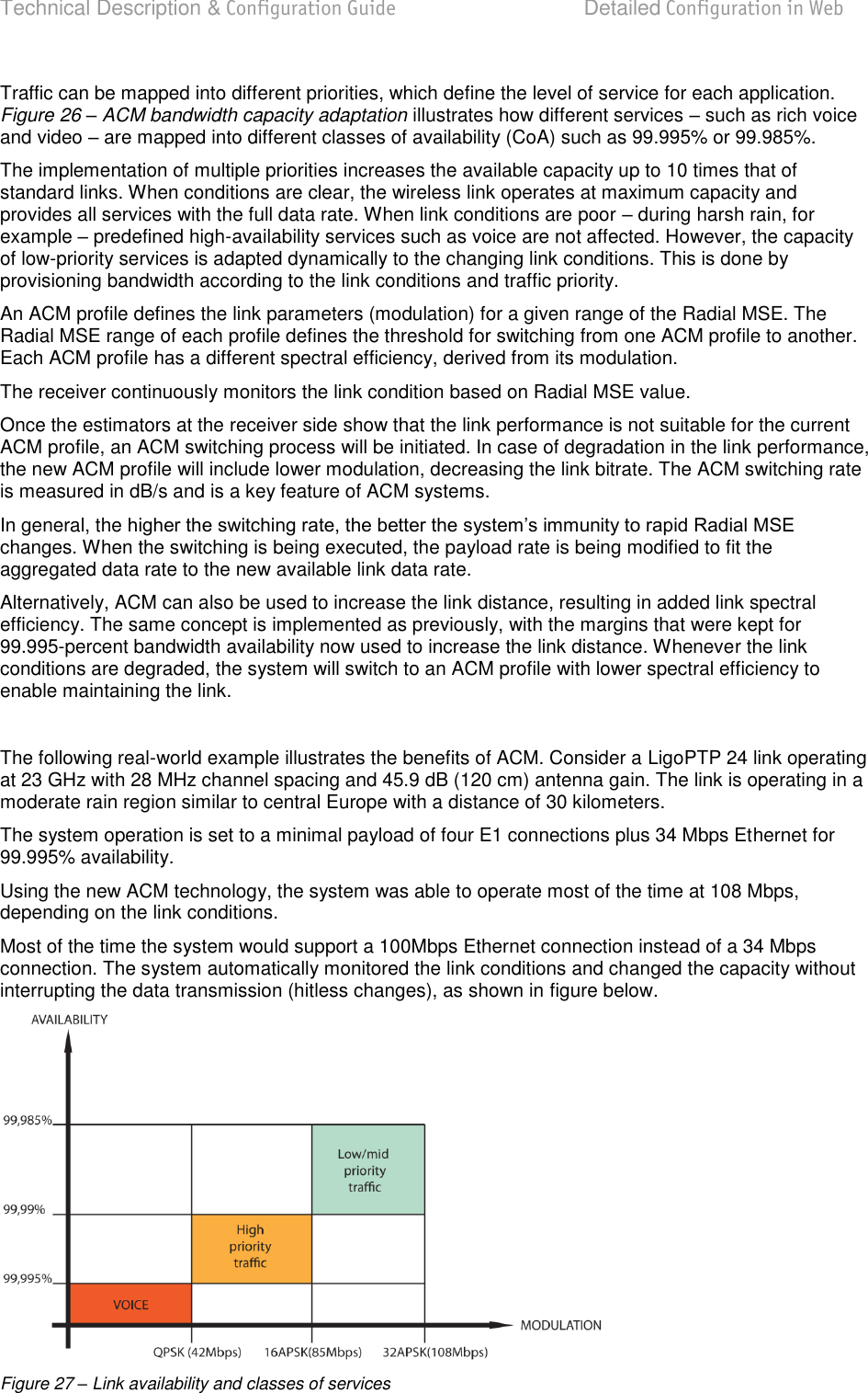
![Technical Description & Configuration Guide Detailed Configuration in Web LigoWave Page 46 Command Description Net telnet <host> [<port>] Opens Telnet session with the FODU, host IP address of the FODU management Ethernet port. Net tftp <host> {get|put} <source> [<destination>] Uploads or downloads (put/get) file (<source>) to or from the host FODU (<host>). Web trace {show|on|off} Web trace allows you to see commands being executed connection. Show – shows web trace status (on or off), on – turns web trace on, off – turns web trace off. Web timeout <time in minutes> Allows setting the time, after which the Web GUI presumes no connectivity state. By default the value is set to 15 minutes. Below is the explanation of the procedure of network IP configuration in case of network IP Class area change. For the purpose of illustration, we use B class IP network address 10.0.10.11 for the remote side LigoPTP 24 and 10.0.10.10 for the local side LigoPTP 24, while the IP address of our management PC LAN adapter will is 10.0.0.1. The steps of the configuration procedure are as follows: Step 1. Enter the remote side (far-end) Web GUI first (in the following case it is 192.168.205.10) and go to IP configuration. The configuration in this particular example will look in the following way: Rollback on should not be selected. Step 2. Enter the local side (close-end) Web GUI and go to IP configuration. The configuration will look in the following way: Rollback on should not be selected. Press Execute configuration. Step 3. Chapter Ethernet Management Connection Configuration. Configuration of LAN Ethernet port must be as follows:](https://usermanual.wiki/LigoWave/PTP24/User-Guide-1302070-Page-46.png)
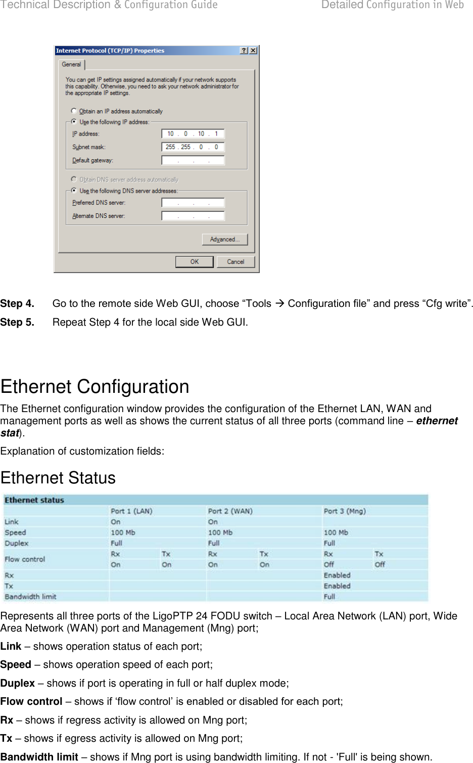
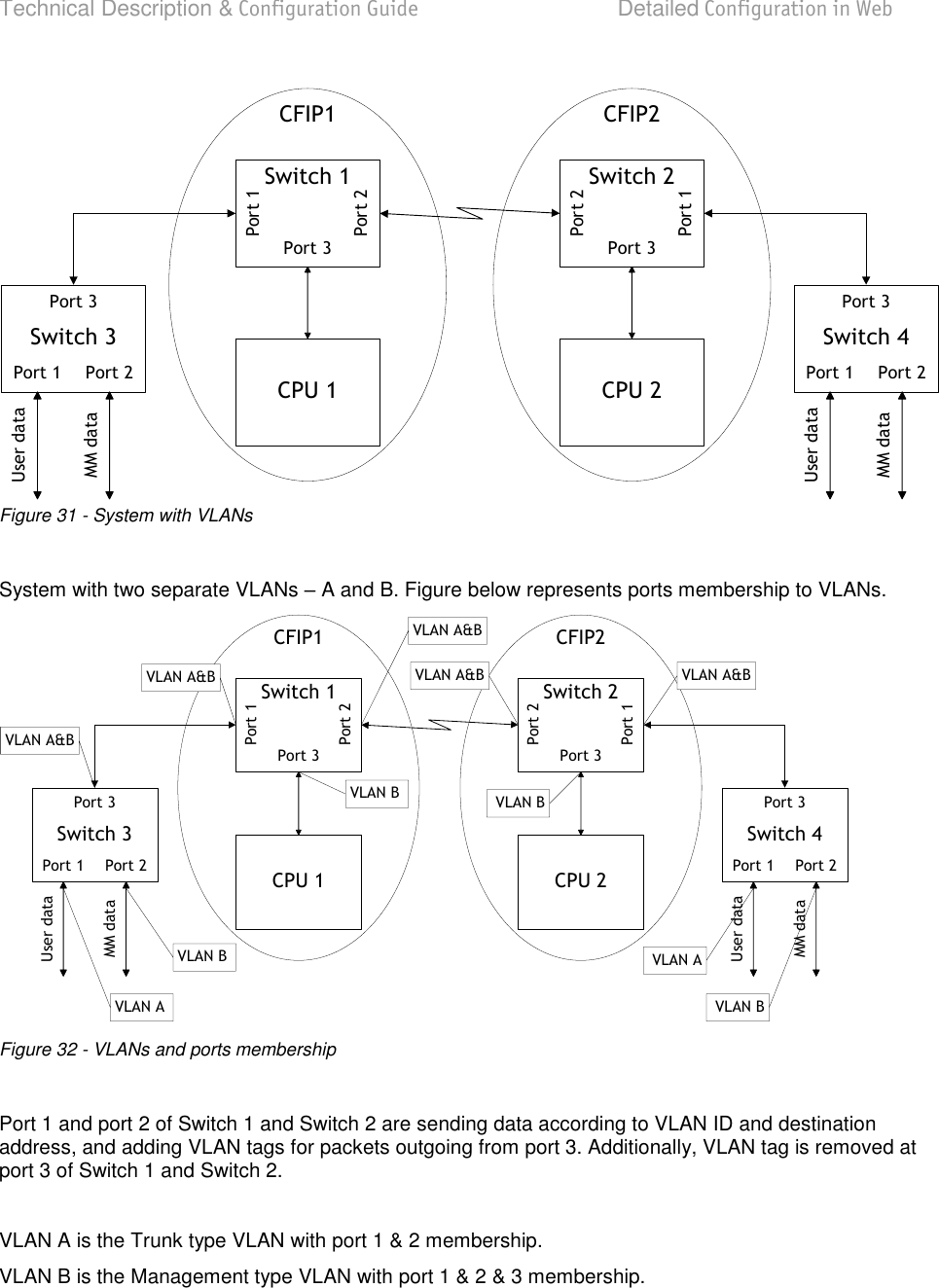
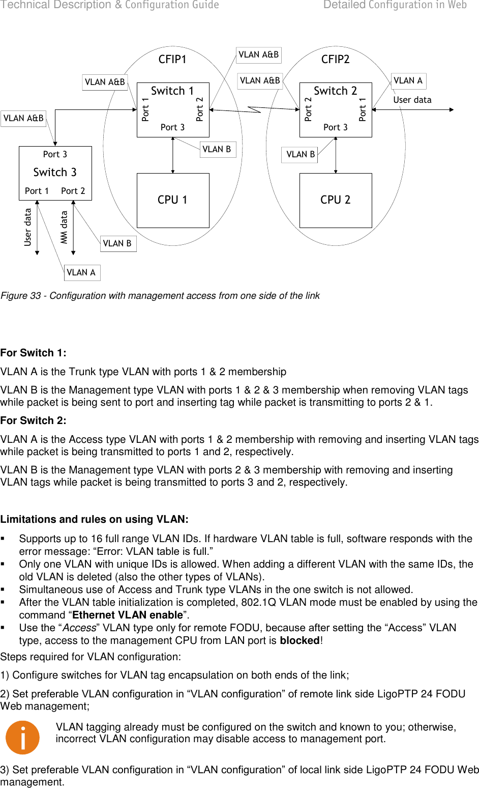
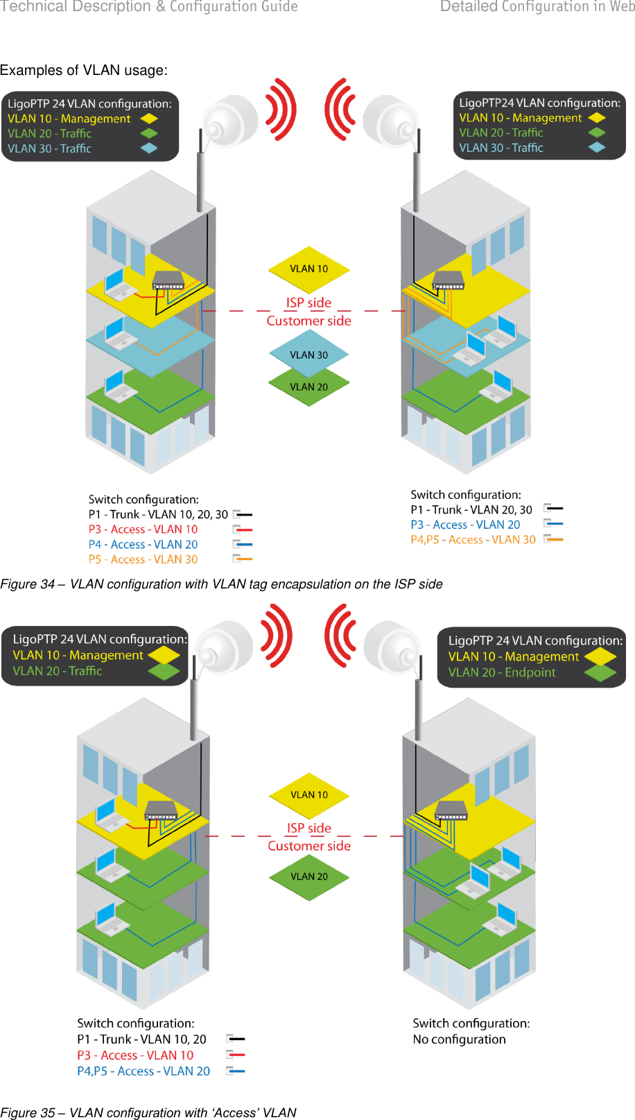
![Technical Description & Configuration Guide Detailed Configuration in Web LigoWave Page 48 Ethernet Configuration LAN connection allows choosing LAN speed and duplex. You are able to choose between 10 Mbps Half Duplex (10hdx), 10 Mbps Full Duplex (10fdx), 100 Mbps Half Duplex (100hdx), 100 Mbps Full ethernet set lan connection [auto|10hdx|10fdx|100hdx|100fdx]); LAN flow control allows enabling or disabling LAN flow control (command line ethernet set lan flowcntrl enable|disable); Mng bandwidth allows limiting bandwidth for the Management port. Possible choices are 128 Kbps, 256 Kbps, 512 Kbps, 1 Mbps, 2 Mbps, 4 Mbps and Full (command line ethernet set mng bandwidth [128 | 256 | 512Kbps | 1 | 2 | 4Mbps | Full]); Pressing Execute configuration applies changes made to the corresponding section only fr the local side LigoPTP 24 FODU. If Rollback on is selected, configuration will be reverted in case of erroneous configuration changes applied; Pressing Execute configuration applies changes made to the corresponding section; Write to config file writes to configuration file all the changes made on the whole page (command line cfg write); FODU returned - in case of error or incorrectly entered parameter value, or other problems on the whole page VLAN Configuration The VLAN configuration window provides configuration of port-based Ethernet Virtual Local Area Networks (VLANs), allowing using up to 16 different VLAN IDs. It is possible to assign 3 different modes to your VLANs Trunk (LAN port is interconnected with WAN port and Management port is not accessible useful for configuring customer VLANs), Management (all ports are interconnected) and Access (all VLAN tagged packets are being untagged at LAN egress port and tagged at LAN ingress port). Note, that Trunk and Access type VLANs cannot be configured together. 802.1Q VLAN enables support of 802.1Q VLAN (command line ethernet vlan [enable | disable]); Management VLAN ID allows specifying Management VLAN ID. When already configured, shows current Management VLAN ID (command line ethernet vlan <VLAN ID> management);](https://usermanual.wiki/LigoWave/PTP24/User-Guide-1302070-Page-48.png)
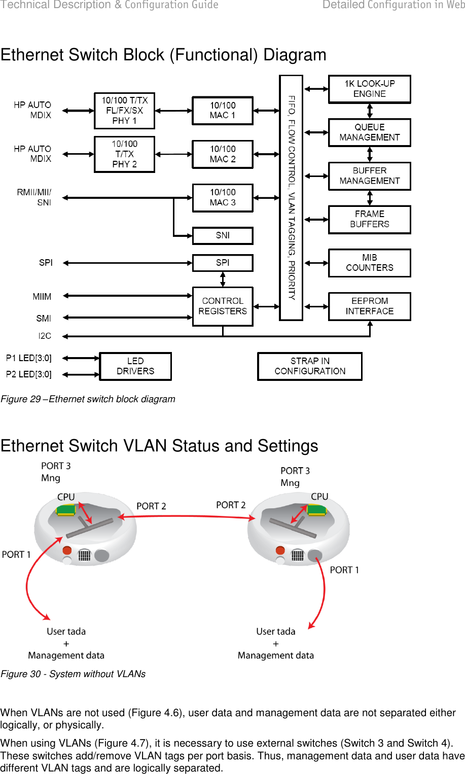
![Technical Description & Configuration Guide Detailed Configuration in Web LigoWave Page 49 LAN port mode specifies LAN port operation mode for user traffic VLANs with tagging/untagging packets (Access) or passing through already tagged packets (Trunk) (command line ethernet vlan <VLAN ID> [Trunk | Access]); Pressing Execute configuration applies changes made to the corresponding section only for the local side LigoPTP 24 configuration changes applied; Trunk VLAN number allows to specify and add Trunk VLAN ID. If Rollback on is selected, configuration will be reverted in case of erroneous configuration changes applied (command line ethernet vlan <VLAN ID> [Trunk | Access]); Reset VLAN resets the whole VLAN configuration (command line ethernet vlan reset); Write to config file writes to configuration file all the changes made on the whole page (command line cfg write); FODU returned in case of error or incorrectly entered parameter value, or other problems on the whole page the info To ensure correct operation of VLANs, both individual VLAN IDs and general 802.1Q VLAN should be enabled. Ethernet Switch Port Status and Settings Switch port 1 (LAN) is connected to LAN interface. Switch port 2 (WAN) is connected to WAN interface, modem and radio part. Switch port 3 (Mng) is connected to LAN Management CPU.](https://usermanual.wiki/LigoWave/PTP24/User-Guide-1302070-Page-49.png)
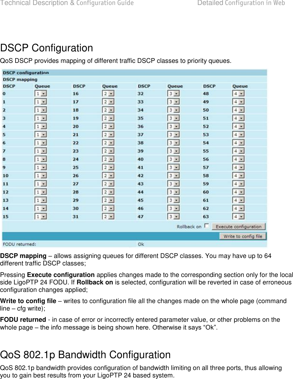
![Technical Description & Configuration Guide Detailed Configuration in Web LigoWave Page 54 QoS QoS Status QoS status provides control over main QoS parameters, accordingly allowing enabling or disabling QoS 802.1p, DiffServ or port based priorities and change priority queuing mode. QoS 802.1p enables or disables 802.1p priorities for all three ports LAN, WAN and Mng (command line ethernet QoS 802.1p {[enable | disable <Port>] | [map]}); DiffServ enables or disables DiffServ (DSCP) priorities for all three ports LAN, WAN and Mng (command line ethernet QoS DSCP [enable | disable <port>] | map); Port based priority allows passing packets from ports (LAN, WAN or Mng) directly to a specific priority queue. By default port based priority queuing passes packets from all ports to lowest (1) priority queue (command line ethernet QoS port <port> <priority>); Priority queuing mode allows choosing fixed priority queuing mode or weighted queue (command line ethernet QoS queuing {[Fixed | Weighted]}): Figure 36 - Weighted priority queuing mode Figure 37 - Fixed priority queuing mode](https://usermanual.wiki/LigoWave/PTP24/User-Guide-1302070-Page-54.png)
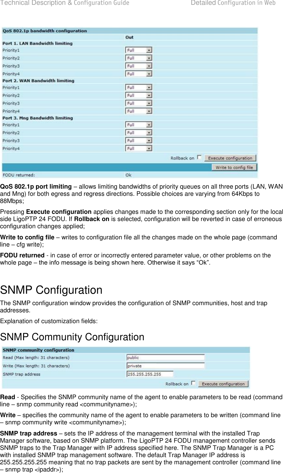
![Technical Description & Configuration Guide Detailed Configuration in Web LigoWave Page 55 In case of weighted priority queuing mode, highest (q3) priority buffer may pass up to 8 consecutive packets subsequently proceeding to lower priority buffer (q2), which may pass up to 4 consecutive packets. This means that highest priority after passing 8 consecutive packets will wait no longer than until 7 packets of lower priorities pass (4(q2)+2(q1)+1(q0)). If any queues are empty, the highest non-empty queue gets one more weighting. For example, if q2 is empty, q3:q2:q1:q0 becomes (8+1):0:2:1. In case of fixed queuing mode, highest priority buffer (q3) will pass packets as long as its buffer is full. By default weighted priority queuing mode is enabled. Priority Buffers shows the state of priority buffers (command line ethernet QoS); QoS 802.1p enables or disables 802.1p priorities for all three ports LAN, WAN and Mng (command line ethernet QoS 802.1p {[enable | disable <Port>] | [map]}); DiffServ enables or disables DiffServ (DSCP) priorities for all three ports LAN, WAN and Mng (command line ethernet QoS DSCP [enable | disable <port>] | map); Port based priority allows passing packets from ports (LAN, WAN or Mng) directly to a specific priority queue. By default port based priority queuing passes packets from all ports to lowest (1) priority queue (command line ethernet QoS port <port> <priority>); Multiple Tx priority queues enables or disables multiple Tx priority queues (command line ethernet QoS priorities {{enable | disable} <Port>}); QoS 802.1p Configuration QoS 802.1p provides configuration of QoS 802.1p priority mapping. You are able to map 8 different traffic 802.1p values (0 7) into 4 priority queues (1 4). QoS 802.1p priority mapping allows assigning queue values to specific 802.1p values. Pressing Execute configuration applies changes made to the corresponding section only for the local side LigoPTP 24 FODU. If Rollback on is selected, configuration will be reverted in case of erroneous configuration changes applied; Write to config file writes to configuration file all the changes made on the whole page (command line cfg write); FODU returned - in case of error or incorrectly entered parameter value, or other problems on the whole page ](https://usermanual.wiki/LigoWave/PTP24/User-Guide-1302070-Page-55.png)
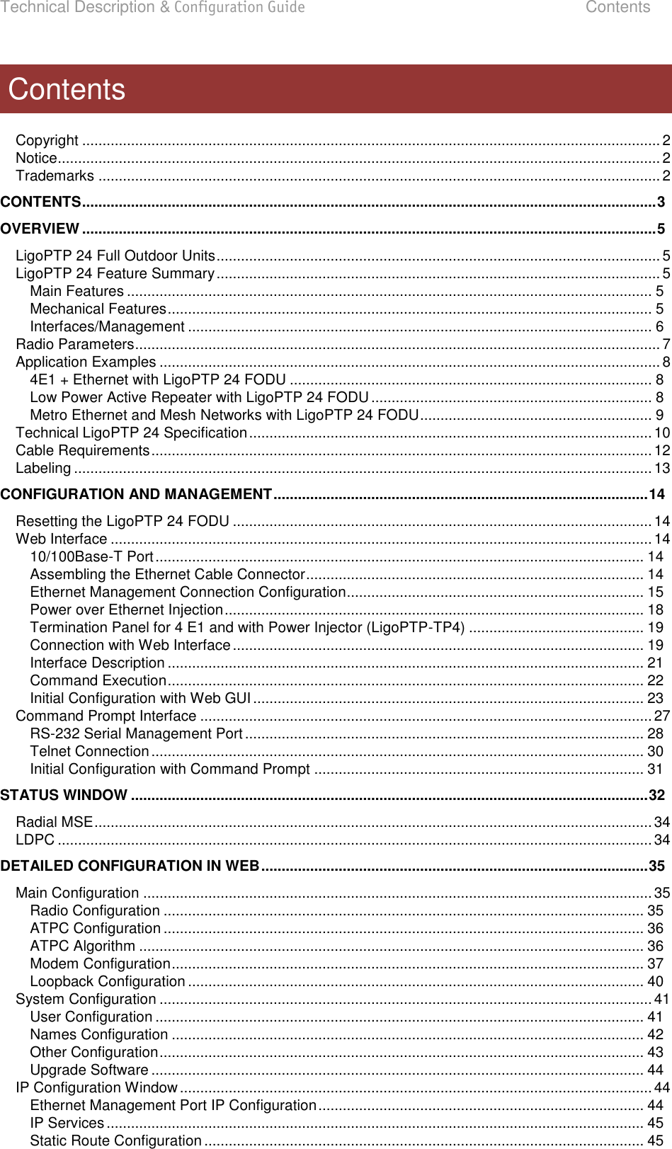
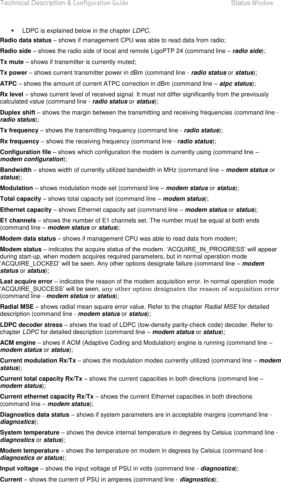
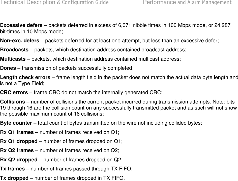
![Technical Description & Configuration Guide Performance and Alarm Management LigoWave Page 59 Alarm Management Alarms and Events Structure All alarms and events are placed in indexed table. Low level raw alarms and events are placed in the first table. Raw alarms and events are merged in groups, which are placed in the second indexed group table. Raw alarm table and group table are related one to many, or one to one if each alarm has a separate group (see Figure 5.1.). Group is in SET state if one or more group members are in SET state. If there is no info about any group member alarm or event state, then there is no info about group state too. Figure 38 – Alarm and group table relation Alarms-Events and Groups Tables Most groups write log when group state changes (Set/Reset), but some groups are only rising. Alarms events and event groups: Alarm ID Group ID Alarm-Event name Description 1 1 ==> System Start Software started [Only rising] 2 2 Invalid device license License is not valid 3 3 License expired License validity has expired 4 4 License will soon expire License validity will soon expire 5 5 Log was Cleared called [Only rising] 6 6 Log ERROR Log data structure missing 7 7 Log TEST Log test was made 8 8 Counters was Cleared System performance counters were cleared [Only rising] 9 9 Config was Written Configuration was written [Only rising] 10 10 System CPU restart ==> Entered when system restart was called [Only rising] 11 11 No data from system temperature sensor No data from temperature sensor connected via I2C interface 12 12 System temperature fault Temperature is out of defined range Performance and Alarm Management 1 alarm_list (indexed table) alarm_idx (index field) alarm_group (group id field) alarm_group_list (indexed table) alarm_goup (index field) ∞ Description fields ... Description fields ...](https://usermanual.wiki/LigoWave/PTP24/User-Guide-1302070-Page-59.png)
![Technical Description & Configuration Guide Performance and Alarm Management LigoWave Page 60 Alarm ID Group ID Alarm-Event name Description 13 13 No data from main PSU ADC No data from the main PSU ADC 14 14 Main supply voltage failure Main supply voltage is out of defined range 15 15 Main supply current failure Main supply current is out of defined range 16 16 Main supply power failure Main supply power is out of defined range 17 17 No data from power supply ADC No data from ADC connected via I2C interface 18 18 1,2V failure Power supply voltage out of defined range 19 18 1,5V failure Power supply voltage out of defined range 20 18 3,3V failure Power supply voltage out of defined range 21 18 5,0V failure Power supply voltage out of defined range 22 18 Permanent 7,5V failure Power supply voltage out of defined range 23 18 Switchable 7,5V failure Power supply voltage out of defined range 24 18 12,0V failure Power supply voltage out of defined range 25 18 -5,0V failure Power supply voltage out of defined range 26 19 No data from RADIO No data from radio (for future compatibility) 27 20 Rx level alarm Rx alarm level is out of defined range 28 21 Tx PLL error alarm Tx PLL failure 29 22 Rx PLL error alarm Rx PLL failure 30 23 No data from MODEM No data from MODEM connected via UART interface 31 24 Acquire status alarm Modem acquire failure status 32 25 Last acquire error status Modem last acquire failure status 33 26 Radial MSE Radial MSE is out of defined range 34 27 LDPC decoder stress LDPC decoder stress is out of defined range 35 28 ACM profile was changed ACM profile was changed 36 29 RX carrier offset Error in Rx carrier offset 37 30 No data from modem temperature sensor No data from modem temperature sensor 38 31 Modem temperature fault Modem temperature is out of defined range 39 32 ATPC Tx power correction was changed ATPC Tx power correction was changed 40 33 Rollback initiate system CPU restart ==> System restart was called by rollback [Only rising] 41 34 System CPU reset was WDT initiated ==> System restart was called by watchdog [Only rising]](https://usermanual.wiki/LigoWave/PTP24/User-Guide-1302070-Page-60.png)
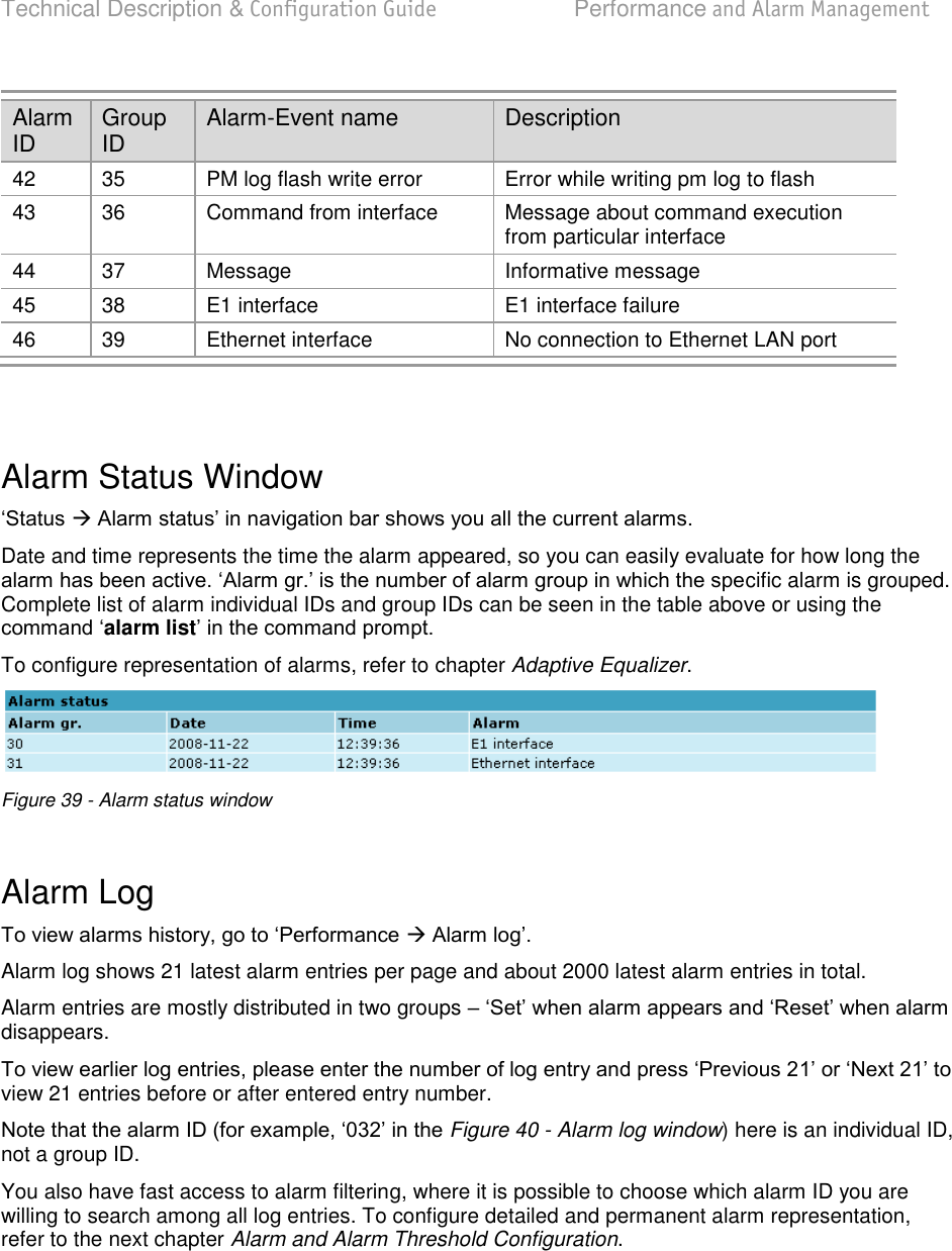
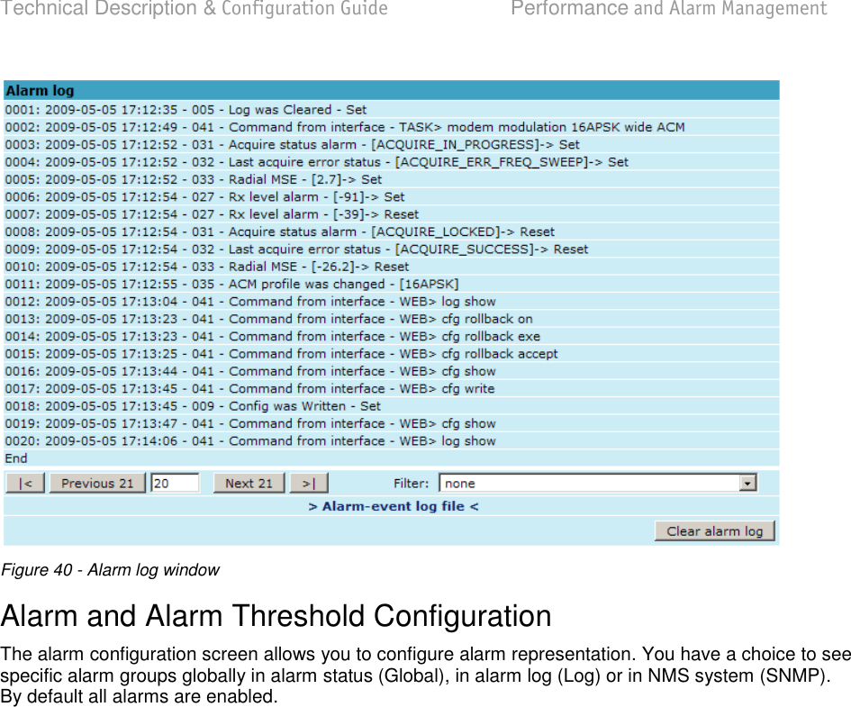
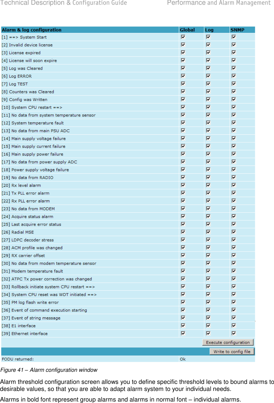
![Technical Description & Configuration Guide Performance and Alarm Management LigoWave Page 64 Figure 42 – Alarm threshold configuration window Alarm Management Commands To manage alarms in command prompt, the commands are as follows: Command Description Log show [<start line>] The management controller maintains event log, - events include configuration changes, management controller restarts, and local site alarm changes. log entries, the log entries are numbered, - entry with the command can be followed up with an entry number to display the latest 20 entries beginning from the entry isplay Log filter <alarm ID> [<num>] Filters event list by specific alarm ID. <start line> ; works Log file <file name> Makes event log file with specified filename. Alarm stat Lists alarm groups currently set. Alarm list Displays the list of all alarms, their group IDs and alarm IDs. Alarm groups Displays the list of all alarms and their group IDs.](https://usermanual.wiki/LigoWave/PTP24/User-Guide-1302070-Page-64.png)
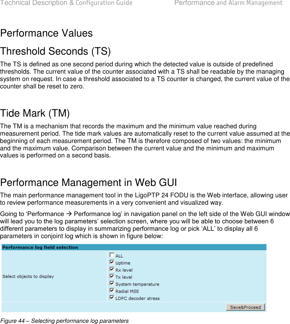
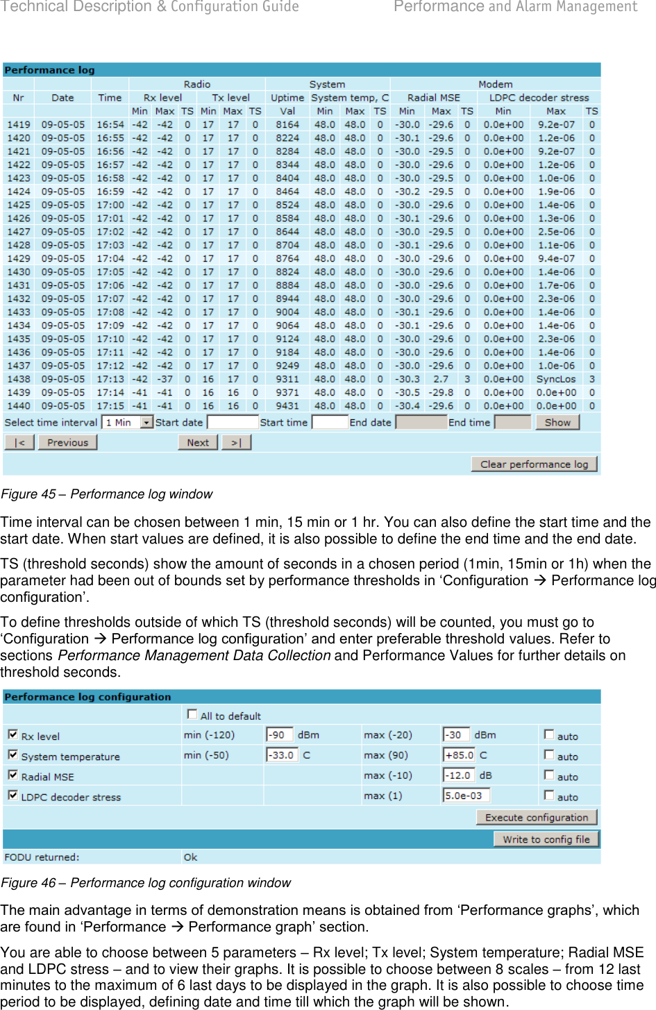
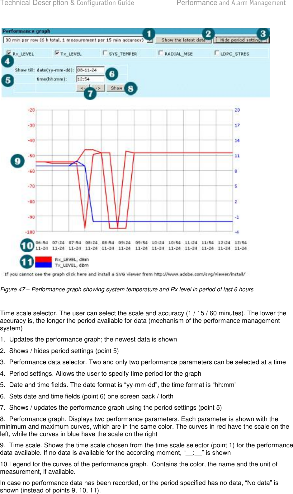
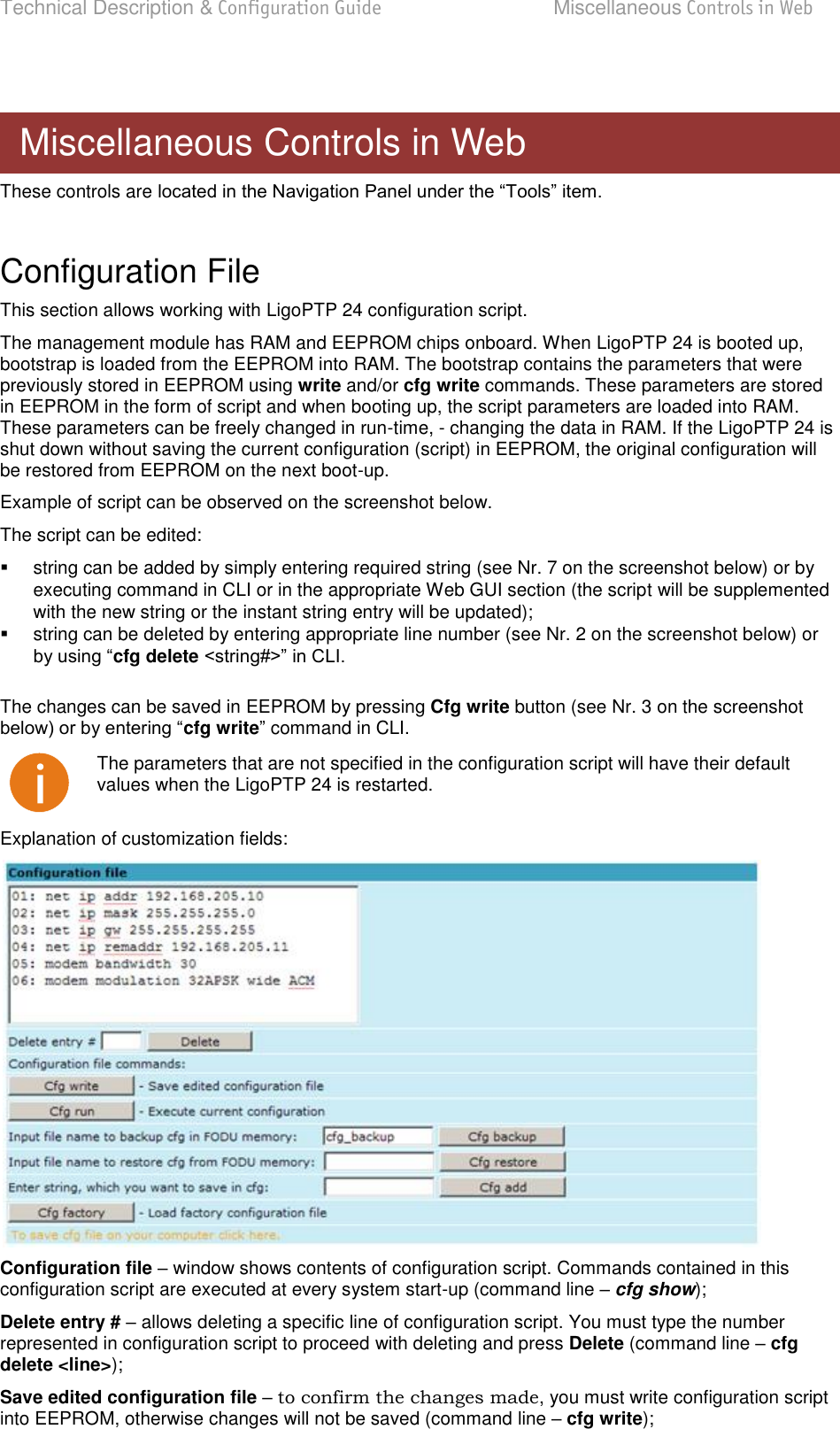
![Technical Description & Configuration Guide Performance and Alarm Management LigoWave Page 65 Command Description Alarm cfg <groupID>[<global><led><aux><log><snmp>] Allows defining detailed alarm representation settings. [<global> <led> <aux> <log> <snmp>] must be defined in Alarm threshold {stat}|{<Alarm ID>lo|hi|delta <value>} Sets threshold values outside which alarm status will be shown. Performance Management The main aim of the performance management is to register mostly critical device performance event values in predefined time intervals. Performance Management Data Collection The performance parameters are collected within time intervals of 1 min., 15 min. and 1 hour. List reserved space for every time interval is 1440 records (see Figure 43 – Functional architecture for data collection, history and thresholding treatment). Second-by-second the input performance event values are stored by updating previous second values. The register is called current register. The current register contains the performance values collected second-by-second from the reset instant to the present second. At the end of period the contents of current registers are transferred to the history registers (records), with a time-date stamp to identify the period, after which the current register must be reset. Some current register values are passed to the threshold crossing control unit for triggering threshold crossing notification. Optionally, the same values are output to the Message Communication Function (MCF) to be forwarded to the managing system. Figure 43 – Functional architecture for data collection, history and thresholding treatment](https://usermanual.wiki/LigoWave/PTP24/User-Guide-1302070-Page-65.png)
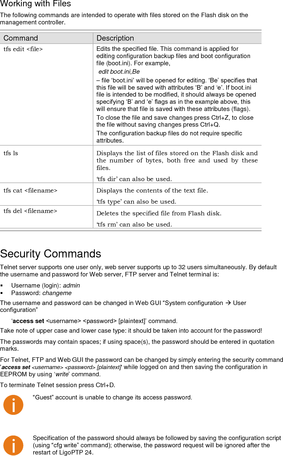
![Technical Description & Configuration Guide Miscellaneous Controls in Web LigoWave Page 79 Working with Files The following commands are intended to operate with files stored on the Flash disk on the management controller. Command Description tfs edit <file> Edits the specified file. This command is applied for editing configuration backup files and boot configuration file (boot.ini). For example, edit boot.ini,Be file is intended to be modified, it should always be opened will ensure that file is saved with these attributes (flags). To close the file and save changes press Ctrl+Z, to close the file without saving changes press Ctrl+Q. The configuration backup files do not require specific attributes. tfs ls Displays the list of files stored on the Flash disk and the number of bytes, both free and used by these files. ‘tfs dir’ can also be used. tfs cat <filename> Displays the contents of the text file. ‘tfs type’ can also be used. tfs del <filename> Deletes the specified file from Flash disk. ‘tfs rm’ can also be used. Security Commands Telnet server supports one user only, web server supports up to 32 users simultaneously. By default the username and password for Web server, FTP server and Telnet terminal is: Username (login): admin Password: changeme User access set Take note of upper case and lower case type: it should be taken into account for the password! The passwords may contain spaces; if using space(s), the password should be entered in quotation marks. For Telnet, FTP and Web GUI the password can be changed by simply entering the security command access set <username> <password> [plaintext]while logged on and then saving the configuration in write To terminate Telnet session press Ctrl+D. Specification of the password should always be followed by saving the configuration script restart of LigoPTP 24.](https://usermanual.wiki/LigoWave/PTP24/User-Guide-1302070-Page-79.png)
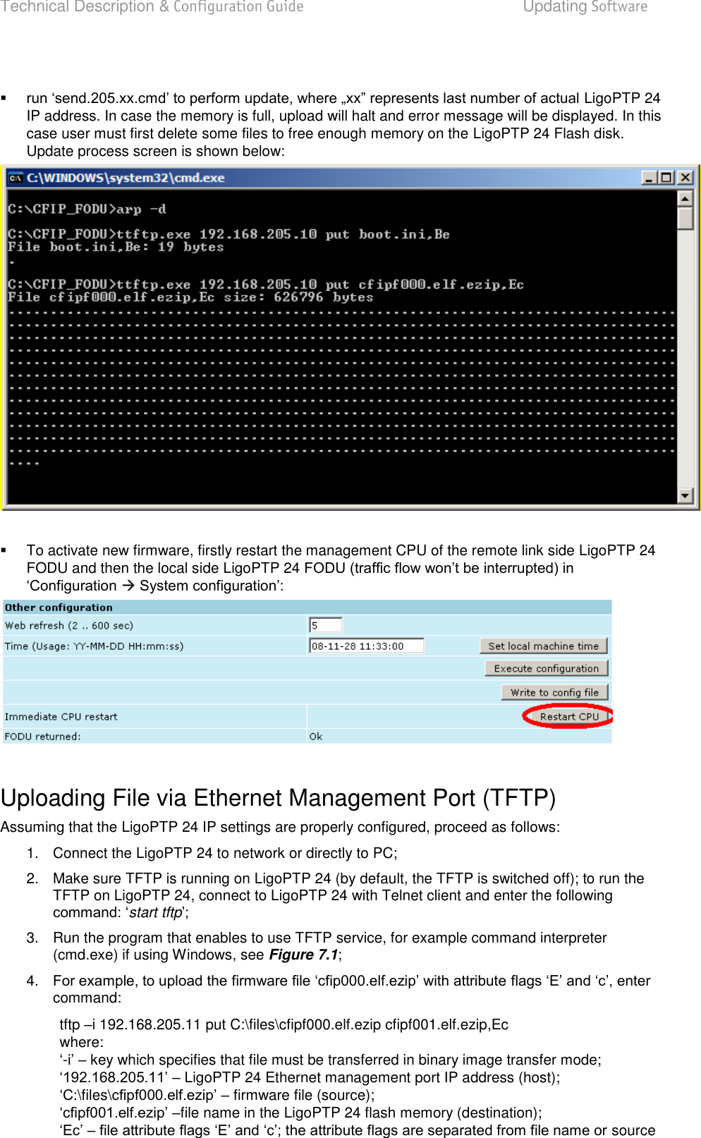
![Technical Description & Configuration Guide Updating Software LigoWave Page 81 To simplify the software update process, LigoWave provides special update package, as a new version is available. This update pack is available as archive (e.g. zip), which includes firmware file (with *.elf.ezip extension), boot configuration file (with *.ini extension) and other files needed for update process. To receive update pack, please contact your LigoWave distributor. The main method for software upgrade is Web GUI software upgrade, which automates the whole Browse… button and locate software upgrade file on your hard disc (see Chapter 4.2.4 for detailed explanation of Web GUI upgrade). Besides there are other various ways how the user can update the LigoPTP 24 management software by uploading the appropriate firmware file to the LigoPTP 24 FODU flash disk and further editing boot configuration file if necessary. The file upload can be performed: via Ethernet management port using update package, via Ethernet management port using FTP, via Ethernet management port using TFTP, or via RS232 serial port using Xmodem protocol. Following chapters describe other methods how to update the software without using update pack. Update Software with Update Pack To update LigoPTP 24 software by using the update pack, proceed as follows: uncompress the package; change the LigoPTP 24 IP address to 192.168.205.10, or LigoPTP 24 IP address; arp d ip_addr [if_addr] deletes the host specified by ip_addr. If another host with a duplicate IP address exists on the network, the ARP cache may have had the MAC address for the other computer placed in it. arp d is used to delete an entry that may be incorrect. By default no host is specified. rem ttftp.exe 192.168.205.10 put help.txt prefix ignores command execution LigoPTP 24 with IP address 192.168.205.10. Updating Software](https://usermanual.wiki/LigoWave/PTP24/User-Guide-1302070-Page-81.png)