Lincoln Electric Im278 D Users Manual
IM278-D to the manual 0bcb496e-e824-4c47-9a07-547d5c03f78d
2015-02-09
: Lincoln-Electric Lincoln-Electric-Im278-D-Users-Manual-574227 lincoln-electric-im278-d-users-manual-574227 lincoln-electric pdf
Open the PDF directly: View PDF ![]() .
.
Page Count: 112 [warning: Documents this large are best viewed by clicking the View PDF Link!]
• Sales and Service through Subsidiaries and Distributors Worldwide •
Cleveland, Ohio 44117-1199 U.S.A. TEL: 216.481.8100 FAX: 216.486.1751 WEB SITE: www.lincolnelectric.com
• World's Leader in Welding and Cutting Products •
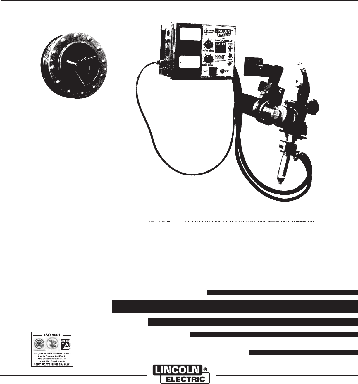
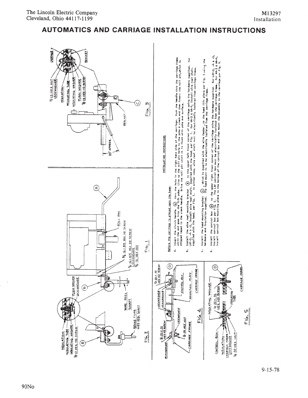
NA-3 AND NA-4
AUTOMATIC WELDING SYSTEMS
OPERATOR’S MANUAL
IM278-D
June, 2008
MODELS
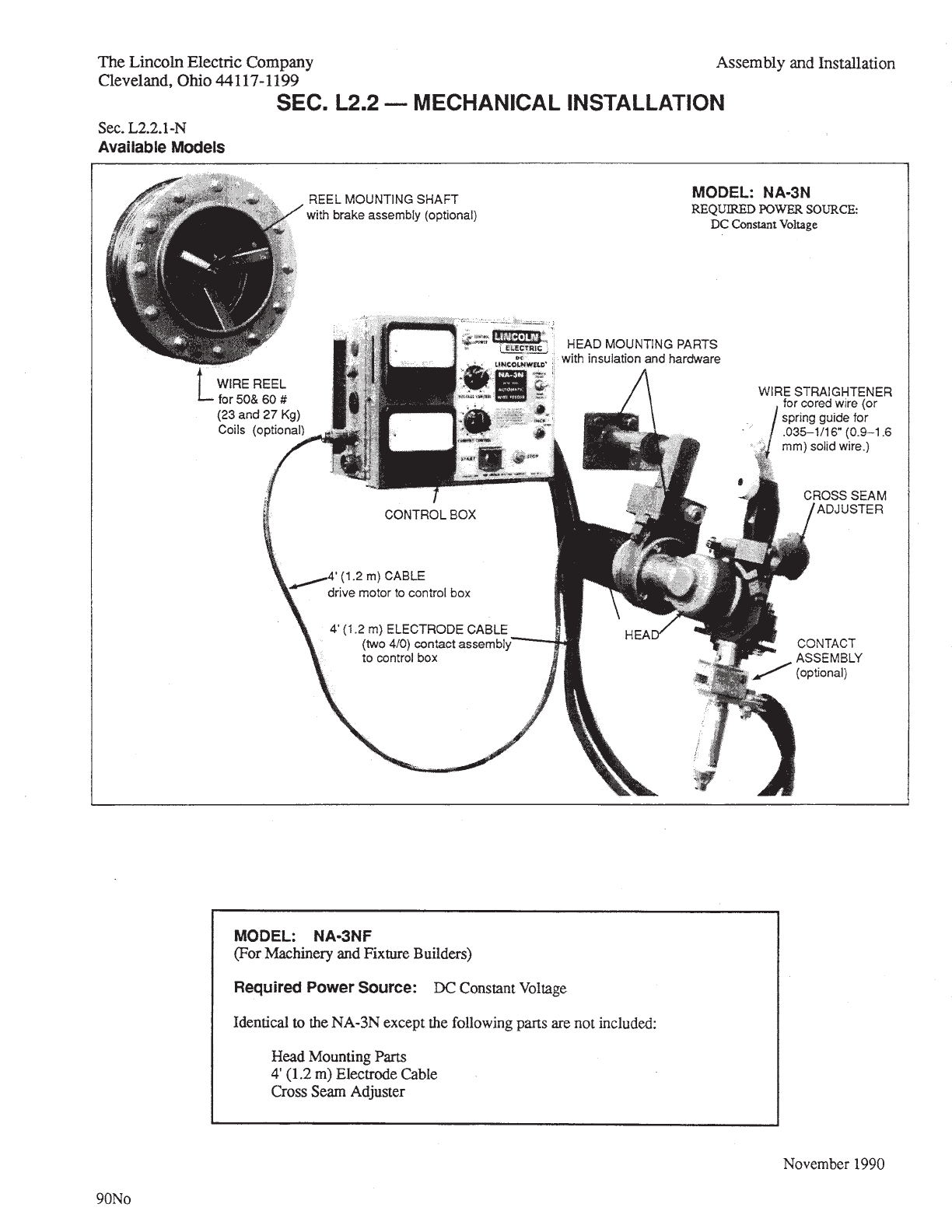
NA-3N
NA-3NF
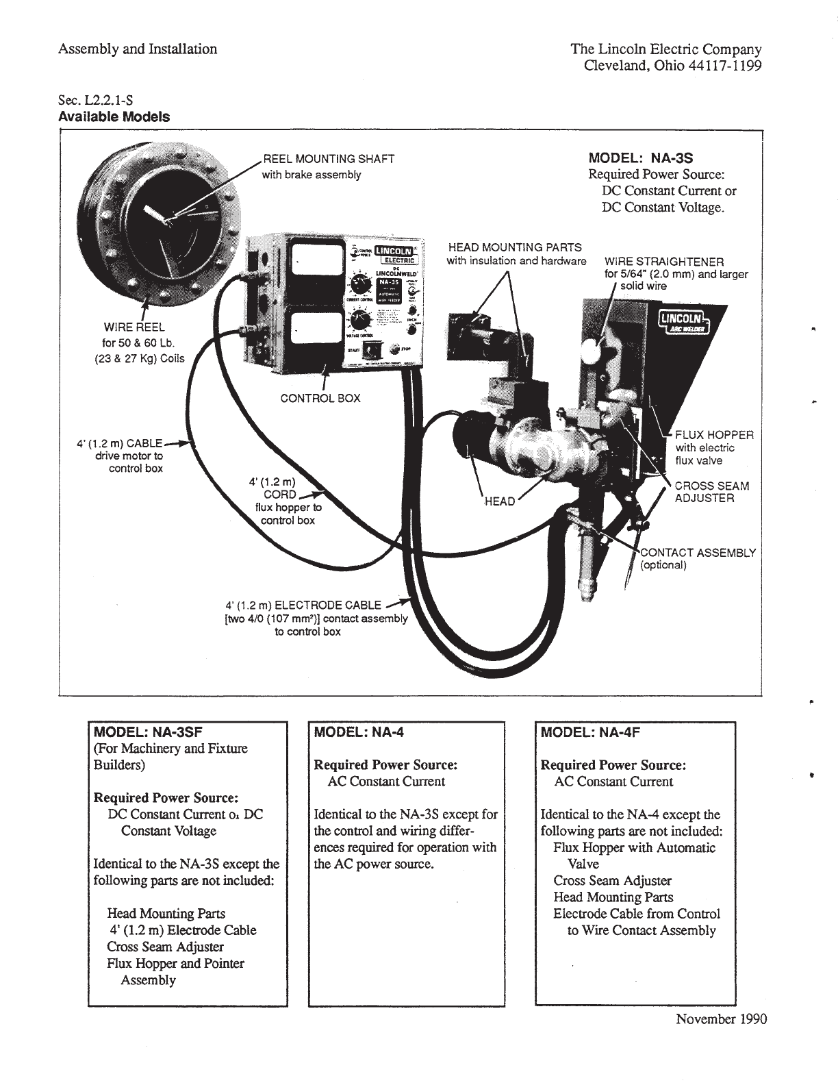
NA-3S
NA3SF
NA-4
SHIPPING DAMAGE CLAIMS:
When this equipment is shipped, title passes to pur-
chaser upon receipt by carrier. Consequently, claims
for material damage in shipment must be made by the
purchaser against the transportation company at the
time the shipment is received.
Copyright © Lincoln Global Inc.
Safety Depends on You
Lincoln arc welding and cutting
equipment is designed and built
with safety in mind. However, your
overall safety can be increased by
proper installation ... and thought-
ful operation on your part. DO
NOT INSTALL, OPERATE OR
REPAIR THIS EQUIPMENT
WITHOUT READING THIS
MANUAL AND THE SAFETY
PRECAUTIONS CONTAINED
THROUGHOUT. And, most
importantly, think before you act
and be careful.
RETURN TO MAIN MENU
FOR ENGINE
powered equipment.
1.a. Turn the engine off before troubleshooting and maintenance
work unless the maintenance work requires it to be running.
____________________________________________________
1.b. Operate engines in open, well-ventilated
areas or vent the engine exhaust fumes
outdoors.
____________________________________________________
1.c. Do not add the fuel near an open flame
welding arc or when the engine is running.
Stop the engine and allow it to cool before
refueling to prevent spilled fuel from vaporiz-
ing on contact with hot engine parts and
igniting. Do not spill fuel when filling tank. If
fuel is spilled, wipe it up and do not start
engine until fumes have been eliminated.
____________________________________________________
1.d. Keep all equipment safety guards, covers and devices in
position and in good repair.Keep hands, hair, clothing and
tools away from V-belts, gears, fans and all other moving
parts when starting, operating or repairing equipment.
____________________________________________________
1.e. In some cases it may be necessary to remove safety
guards to perform required maintenance. Remove
guards only when necessary and replace them when the
maintenance requiring their removal is complete.
Always use the greatest care when working near moving
parts.
___________________________________________________
1.f. Do not put your hands near the engine fan.
Do not attempt to override the governor or
idler by pushing on the throttle control rods
while the engine is running.
___________________________________________________
1.g. To prevent accidentally starting gasoline engines while
turning the engine or welding generator during maintenance
work, disconnect the spark plug wires, distributor cap or
magneto wire as appropriate.
i
SAFETY
i
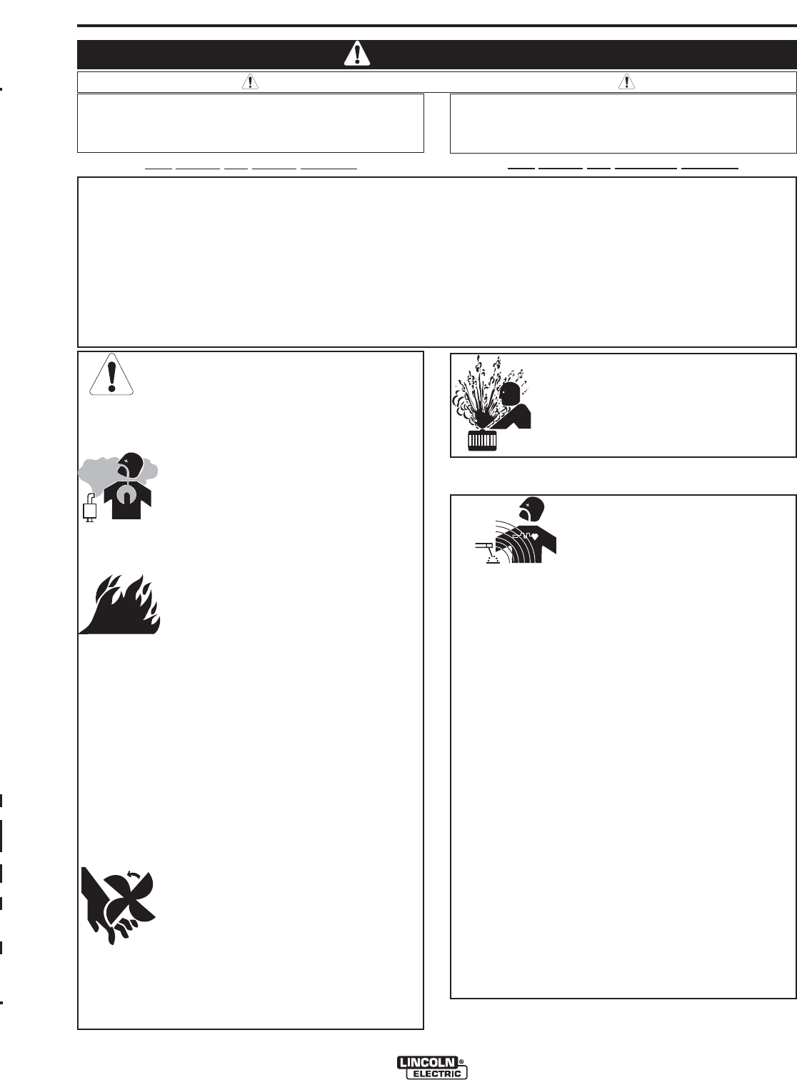
ARC WELDING CAN BE HAZARDOUS. PROTECT YOURSELF AND OTHERS FROM POSSIBLE SERIOUS INJURY OR DEATH.
KEEP CHILDREN AWAY. PACEMAKER WEARERS SHOULD CONSULT WITH THEIR DOCTOR BEFORE OPERATING.
Read and understand the following safety highlights. For additional safety information, it is strongly recommended that you
purchase a copy of “Safety in Welding & Cutting - ANSI Standard Z49.1” from the American Welding Society, P.O. Box
351040, Miami, Florida 33135 or CSA Standard W117.2-1974. A Free copy of “Arc Welding Safety” booklet E205 is available
from the Lincoln Electric Company, 22801 St. Clair Avenue, Cleveland, Ohio 44117-1199.
BE SURE THAT ALL INSTALLATION, OPERATION, MAINTENANCE AND REPAIR PROCEDURES ARE
PERFORMED ONLY BY QUALIFIED INDIVIDUALS.
WARNING
Mar ʻ95
ELECTRIC AND
MAGNETIC FIELDS
may be dangerous
2.a. Electric current flowing through any conductor causes
localized Electric and Magnetic Fields (EMF). Welding
current creates EMF fields around welding cables and
welding machines
2.b. EMF fields may interfere with some pacemakers, and
welders having a pacemaker should consult their physician
before welding.
2.c. Exposure to EMF fields in welding may have other health
effects which are now not known.
2.d. All welders should use the following procedures in order to
minimize exposure to EMF fields from the welding circuit:
2.d.1.
Route the electrode and work cables together - Secure
them with tape when possible.
2.d.2. Never coil the electrode lead around your body.
2.d.3. Do not place your body between the electrode and
work cables. If the electrode cable is on your right
side, the work cable should also be on your right side.
2.d.4. Connect the work cable to the workpiece as close as
possible to the area being welded.
2.d.5. Do not work next to welding power source.
1.h. To avoid scalding, do not remove the
radiator pressure cap when the engine is
hot.
CALIFORNIA PROPOSITION 65 WARNINGS
Diesel engine exhaust and some of its constituents
are known to the State of California to cause can-
cer, birth defects, and other reproductive harm.
The engine exhaust from this product contains
chemicals known to the State of California to cause
cancer, birth defects, or other reproductive harm.
The Above For Diesel Engines The Above For Gasoline Engines
ii
SAFETY
ii
ARC RAYS can burn.
4.a. Use a shield with the proper filter and cover
plates to protect your eyes from sparks and
the rays of the arc when welding or observing
open arc welding. Headshield and filter lens
should conform to ANSI Z87. I standards.
4.b. Use suitable clothing made from durable flame-resistant
material to protect your skin and that of your helpers from
the arc rays.
4.c. Protect other nearby personnel with suitable, non-flammable
screening and/or warn them not to watch the arc nor expose
themselves to the arc rays or to hot spatter or metal.
ELECTRIC SHOCK can
kill.
3.a. The electrode and work (or ground) circuits
are electrically “hot” when the welder is on.
Do not touch these “hot” parts with your bare
skin or wet clothing. Wear dry, hole-free
gloves to insulate hands.
3.b. Insulate yourself from work and ground using dry insulation.
Make certain the insulation is large enough to cover your full
area of physical contact with work and ground.
In addition to the normal safety precautions, if welding
must be performed under electrically hazardous
conditions (in damp locations or while wearing wet
clothing; on metal structures such as floors, gratings or
scaffolds; when in cramped positions such as sitting,
kneeling or lying, if there is a high risk of unavoidable or
accidental contact with the workpiece or ground) use
the following equipment:
• Semiautomatic DC Constant Voltage (Wire) Welder.
• DC Manual (Stick) Welder.
• AC Welder with Reduced Voltage Control.
3.c. In semiautomatic or automatic wire welding, the electrode,
electrode reel, welding head, nozzle or semiautomatic
welding gun are also electrically “hot”.
3.d. Always be sure the work cable makes a good electrical
connection with the metal being welded. The connection
should be as close as possible to the area being welded.
3.e. Ground the work or metal to be welded to a good electrical
(earth) ground.
3.f.
Maintain the electrode holder, work clamp, welding cable and
welding machine in good, safe operating condition. Replace
damaged insulation.
3.g. Never dip the electrode in water for cooling.
3.h. Never simultaneously touch electrically “hot” parts of
electrode holders connected to two welders because voltage
between the two can be the total of the open circuit voltage
of both welders.
3.i. When working above floor level, use a safety belt to protect
yourself from a fall should you get a shock.
3.j. Also see Items 6.c. and 8.
FUMES AND GASES
can be dangerous.
5.a. Welding may produce fumes and gases
hazardous to health. Avoid breathing these
fumes and gases. When welding, keep
your head out of the fume. Use enough
ventilation and/or exhaust at the arc to keep
fumes and gases away from the breathing zone. When
welding with electrodes which require special
ventilation such as stainless or hard facing (see
instructions on container or MSDS) or on lead or
cadmium plated steel and other metals or coatings
which produce highly toxic fumes, keep exposure as
low as possible and below Threshold Limit Values (TLV)
using local exhaust or mechanical ventilation. In
confined spaces or in some circumstances, outdoors, a
respirator may be required. Additional precautions are
also required when welding on galvanized steel.
5. b. The operation of welding fume control equipment is affected
by various factors including proper use and positioning of
the equipment, maintenance of the equipment and the spe-
cific welding procedure and application involved. Worker
exposure level should be checked upon installation and
periodically thereafter to be certain it is within applicable
OSHA PEL and ACGIH TLV limits.
5.c.
Do not weld in locations near chlorinated hydrocarbon
vapors
coming from degreasing, cleaning or spraying operations.
The heat and rays of the arc can react with solvent vapors
to
form phosgene, a highly toxic gas, and other irritating prod-
ucts.
5.d. Shielding gases used for arc welding can displace air and
cause injury or death. Always use enough ventilation,
especially in confined areas, to insure breathing air is safe.
5.e. Read and understand the manufacturerʼs instructions for this
equipment and the consumables to be used, including the
material safety data sheet (MSDS) and follow your
employerʼs safety practices. MSDS forms are available from
your welding distributor or from the manufacturer.
5.f. Also see item 1.b.
AUG 06
iii
SAFETY
iii
FOR ELECTRICALLY
powered equipment.
8.a. Turn off input power using the disconnect
switch at the fuse box before working on
the equipment.
8.b. Install equipment in accordance with the U.S. National
Electrical Code, all local codes and the manufacturerʼs
recommendations.
8.c. Ground the equipment in accordance with the U.S. National
Electrical Code and the manufacturerʼs recommendations.
CYLINDER may explode
if damaged.
7.a. Use only compressed gas cylinders
containing the correct shielding gas for the
process used and properly operating
regulators designed for the gas and
pressure used. All hoses, fittings, etc. should be suitable for
the application and maintained in good condition.
7.b. Always keep cylinders in an upright position securely
chained to an undercarriage or fixed support.
7.c. Cylinders should be located:
• Away from areas where they may be struck or subjected to
physical damage.
• A safe distance from arc welding or cutting operations and
any other source of heat, sparks, or flame.
7.d. Never allow the electrode, electrode holder or any other
electrically “hot” parts to touch a cylinder.
7.e. Keep your head and face away from the cylinder valve outlet
when opening the cylinder valve.
7.f. Valve protection caps should always be in place and hand
tight except when the cylinder is in use or connected for
use.
7.g. Read and follow the instructions on compressed gas
cylinders, associated equipment, and CGA publication P-l,
“Precautions for Safe Handling of Compressed Gases in
Cylinders,” available from the Compressed Gas Association
1235 Jefferson Davis Highway, Arlington, VA 22202.
Jan, 07
WELDING and CUTTING
SPARKS can
cause fire or explosion.
6.a.
Remove fire hazards from the welding area.
If this is not possible, cover them to prevent
the welding sparks from starting a fire.
Remember that welding sparks and hot
materials from welding can easily go through small cracks
and openings to adjacent areas. Avoid welding near
hydraulic lines. Have a fire extinguisher readily available.
6.b. Where compressed gases are to be used at the job site,
special precautions should be used to prevent hazardous
situations. Refer to “Safety in Welding and Cutting” (ANSI
Standard Z49.1) and the operating information for the
equipment being used.
6.c. When not welding, make certain no part of the electrode
circuit is touching the work or ground. Accidental contact
can cause overheating and create a fire hazard.
6.d. Do not heat, cut or weld tanks, drums or containers until the
proper steps have been taken to insure that such procedures
will not cause flammable or toxic vapors from substances
inside. They can cause an explosion even
though
they have
been “cleaned”. For information, purchase “Recommended
Safe Practices for the
Preparation
for Welding and Cutting of
Containers and Piping That Have Held Hazardous
Substances”, AWS F4.1 from the American Welding Society
(see address above).
6.e. Vent hollow castings or containers before heating, cutting or
welding. They may explode.
6.f.
Sparks and spatter are thrown from the welding arc. Wear oil
free protective garments such as leather gloves, heavy shirt,
cuffless trousers, high shoes and a cap over your hair. Wear
ear plugs when welding out of position or in confined places.
Always wear safety glasses with side shields when in a
welding area.
6.g. Connect the work cable to the work as close to the welding
area as practical. Work cables connected to the building
framework or other locations away from the welding area
increase the possibility of the welding current passing
through lifting chains, crane cables or other alternate cir-
cuits. This can create fire hazards or overheat lifting chains
or cables until they fail.
6.h. Also see item 1.c.
6.I. Read and follow NFPA 51B “ Standard for Fire Prevention
During Welding, Cutting and Other Hot Work”, available
from NFPA,1 Batterymarch Park,PO box 9101, Quincy, Ma
022690-9101.
6.j. Do not use a welding power source for pipe thawing.

iv
SAFETY
iv
PRÉCAUTIONS DE SÛRETÉ
Pour votre propre protection lire et observer toutes les instructions
et les précautions de sûreté specifiques qui parraissent dans ce
manuel aussi bien que les précautions de sûreté générales suiv-
antes:
Sûreté Pour Soudage A LʼArc
1. Protegez-vous contre la secousse électrique:
a. Les circuits à lʼélectrode et à la piéce sont sous tension
quand la machine à souder est en marche. Eviter toujours
tout contact entre les parties sous tension et la peau nue
ou les vétements mouillés. Porter des gants secs et sans
trous pour isoler les mains.
b. Faire trés attention de bien sʼisoler de la masse quand on
soude dans des endroits humides, ou sur un plancher
metallique ou des grilles metalliques, principalement dans
les positions assis ou couché pour lesquelles une grande
partie du corps peut être en contact avec la masse.
c. Maintenir le porte-électrode, la pince de masse, le câble
de soudage et la machine à souder en bon et sûr état
defonctionnement.
d.Ne jamais plonger le porte-électrode dans lʼeau pour le
refroidir.
e. Ne jamais toucher simultanément les parties sous tension
des porte-électrodes connectés à deux machines à souder
parce que la tension entre les deux pinces peut être le
total de la tension à vide des deux machines.
f. Si on utilise la machine à souder comme une source de
courant pour soudage semi-automatique, ces precautions
pour le porte-électrode sʼapplicuent aussi au pistolet de
soudage.
2. Dans le cas de travail au dessus du niveau du sol, se protéger
contre les chutes dans le cas ou on recoit un choc. Ne jamais
enrouler le câble-électrode autour de nʼimporte quelle partie
du corps.
3. Un coup dʼarc peut être plus sévère quʼun coup de soliel,
donc:
a. Utiliser un bon masque avec un verre filtrant approprié
ainsi quʼun verre blanc afin de se protéger les yeux du ray-
onnement de lʼarc et des projections quand on soude ou
quand on regarde lʼarc.
b. Porter des vêtements convenables afin de protéger la
peau de soudeur et des aides contre le rayonnement de
lʻarc.
c. Protéger lʼautre personnel travaillant à proximité au
soudage à lʼaide dʼécrans appropriés et non-inflammables.
4. Des gouttes de laitier en fusion sont émises de lʼarc de
soudage. Se protéger avec des vêtements de protection libres
de lʼhuile, tels que les gants en cuir, chemise épaisse, pan-
talons sans revers, et chaussures montantes.
5. Toujours porter des lunettes de sécurité dans la zone de
soudage. Utiliser des lunettes avec écrans lateraux dans les
zones où lʼon pique le laitier.
6. Eloigner les matériaux inflammables ou les recouvrir afin de
prévenir tout risque dʼincendie dû aux étincelles.
7. Quand on ne soude pas, poser la pince à une endroit isolé de
la masse. Un court-circuit accidental peut provoquer un
échauffement et un risque dʼincendie.
8. Sʼassurer que la masse est connectée le plus prés possible
de la zone de travail quʼil est pratique de le faire. Si on place
la masse sur la charpente de la construction ou dʼautres
endroits éloignés de la zone de travail, on augmente le risque
de voir passer le courant de soudage par les chaines de lev-
age, câbles de grue, ou autres circuits. Cela peut provoquer
des risques dʼincendie ou dʼechauffement des chaines et des
câbles jusquʼà ce quʼils se rompent.
9. Assurer une ventilation suffisante dans la zone de soudage.
Ceci est particuliérement important pour le soudage de tôles
galvanisées plombées, ou cadmiées ou tout autre métal qui
produit des fumeés toxiques.
10. Ne pas souder en présence de vapeurs de chlore provenant
dʼopérations de dégraissage, nettoyage ou pistolage. La
chaleur ou les rayons de lʼarc peuvent réagir avec les vapeurs
du solvant pour produire du phosgéne (gas fortement toxique)
ou autres produits irritants.
11. Pour obtenir de plus amples renseignements sur la sûreté,
voir le code “Code for safety in welding and cutting” CSA
Standard W 117.2-1974.
PRÉCAUTIONS DE SÛRETÉ POUR
LES MACHINES À SOUDER À
TRANSFORMATEUR ET À
REDRESSEUR
1. Relier à la terre le chassis du poste conformement au code de
lʼélectricité et aux recommendations du fabricant. Le dispositif
de montage ou la piece à souder doit être branché à une
bonne mise à la terre.
2. Autant que possible, Iʼinstallation et lʼentretien du poste seront
effectués par un électricien qualifié.
3. Avant de faires des travaux à lʼinterieur de poste, la debranch-
er à lʼinterrupteur à la boite de fusibles.
4. Garder tous les couvercles et dispositifs de sûreté à leur
place.
Mar. ʻ93

vv
Thank You
for selecting a QUALITY product by Lincoln Electric. We want you
to take pride in operating this Lincoln Electric Company product
••• as much pride as we have in bringing this product to you!
Read this Operators Manual completely before attempting to use this equipment. Save this manual and keep it
handy for quick reference. Pay particular attention to the safety instructions we have provided for your protection.
The level of seriousness to be applied to each is explained below:
WARNING
This statement appears where the information must be followed exactly to avoid serious personal injury or loss of life.
This statement appears where the information must be followed to avoid minor personal injury or damage to this equipment.
CAUTION
Please Examine Carton and Equipment For Damage Immediately
When this equipment is shipped, title passes to the purchaser upon receipt by the carrier. Consequently, Claims
for material damaged in shipment must be made by the purchaser against the transportation company at the
time the shipment is received.
Please record your equipment identification information below for future reference. This information can be
found on your machine nameplate.
Product _________________________________________________________________________________
Model Number ___________________________________________________________________________
Code Number or Date Code_________________________________________________________________
Serial Number____________________________________________________________________________
Date Purchased___________________________________________________________________________
Where Purchased_________________________________________________________________________
Whenever you request replacement parts or information on this equipment, always supply the information you
have recorded above. The code number is especially important when identifying the correct replacement parts.
On-Line Product Registration
- Register your machine with Lincoln Electric either via fax or over the Internet.
• For faxing: Complete the form on the back of the warranty statement included in the literature packet
accompanying this machine and fax the form per the instructions printed on it.
• For On-Line Registration: Go to our
WEB SITE at www.lincolnelectric.com. Choose “Quick Links” and then
“Product Registration”. Please complete the form and submit your registration.
CUSTOMER ASSISTANCE POLICY
The business of The Lincoln Electric Company is manufacturing and selling high quality welding equipment, consumables, and cutting equip-
ment. Our challenge is to meet the needs of our customers and to exceed their expectations. On occasion, purchasers may ask Lincoln
Electric for advice or information about their use of our products. We respond to our customers based on the best information in our posses-
sion at that time. Lincoln Electric is not in a position to warrant or guarantee such advice, and assumes no liability, with respect to such infor-
mation or advice. We expressly disclaim any warranty of any kind, including any warranty of fitness for any customerʼs particular purpose,
with respect to such information or advice. As a matter of practical consideration, we also cannot assume any responsibility for updating or
correcting any such information or advice once it has been given, nor does the provision of information or advice create, expand or alter any
warranty with respect to the sale of our products.
Lincoln Electric is a responsive manufacturer, but the selection and use of specific products sold by Lincoln Electric is solely within the control
of, and remains the sole responsibility of the customer. Many variables beyond the control of Lincoln Electric affect the results obtained in
applying these types of fabrication methods and service requirements.
Subject to Change – This information is accurate to the best of our knowledge at the time of printing. Please refer to www.lincolnelectric.com
for any updated information.


http://www.lincolnelectric.com/knowledge/articles/
content/steelhatconstruction.asp
FALLING
EQUIPMENT can
cause injury
s 5SE EQUIPMENT RATED TO LIFT WEIGHT OF THIS DRUM
s IF POSSIBLE LIFT FROM BOTTOM
s &OR TOP LIFTING
n ,IFT ONLY WHEN COVER LOCKED IN PLACE
n ,IFTING DEVICE CONTACT WITH UNDERSIDE OF CLOSING RING MUST BE
AT LEAST INCHES
s .EVER STAND UNDER A LIFTED LAOD
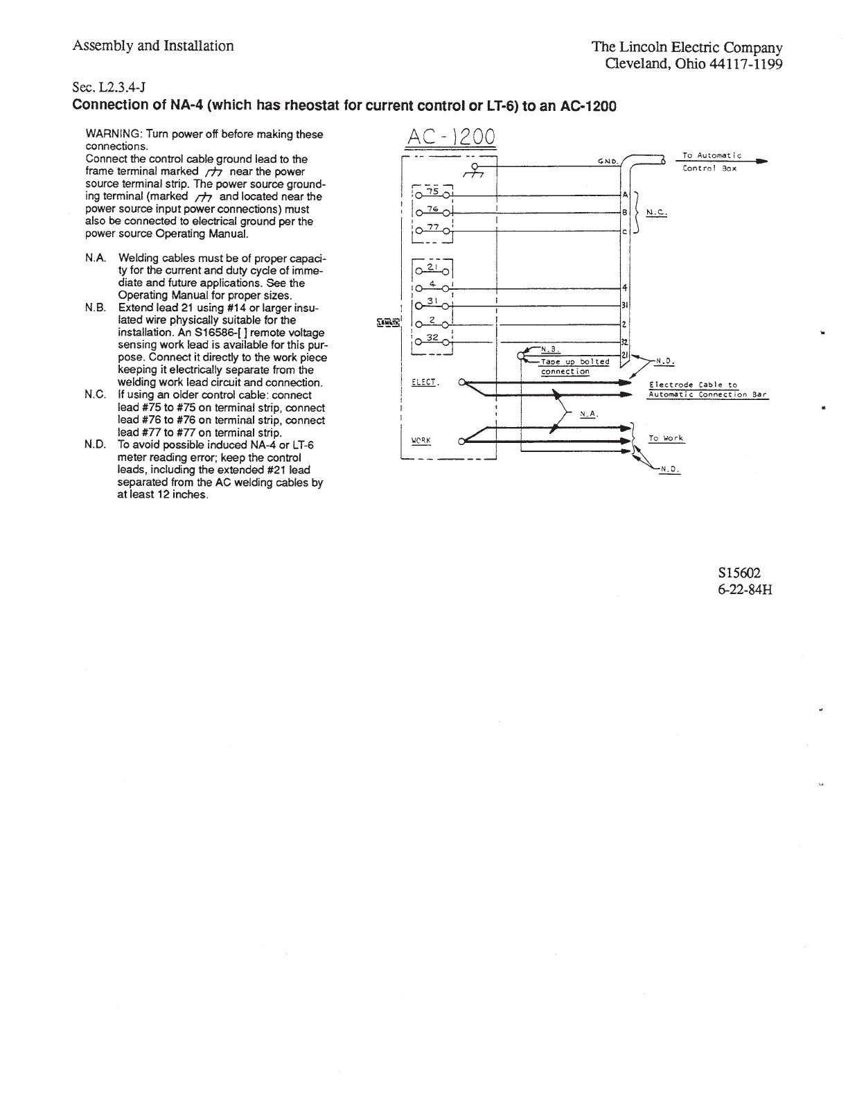
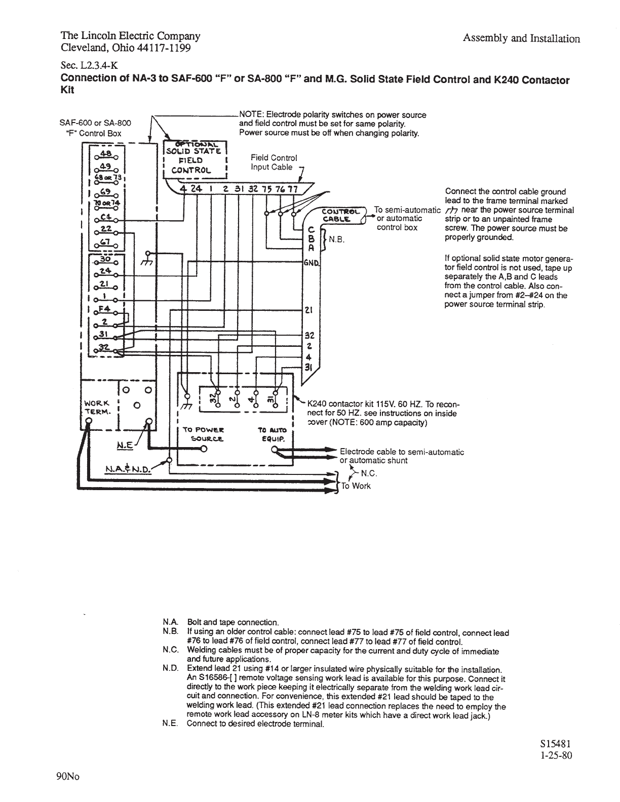
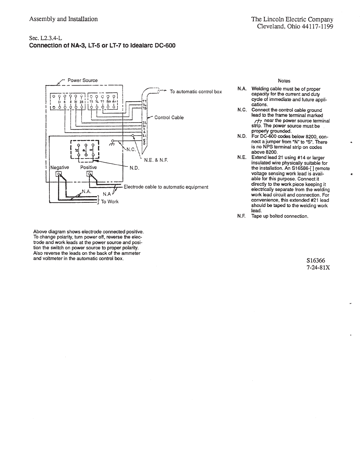
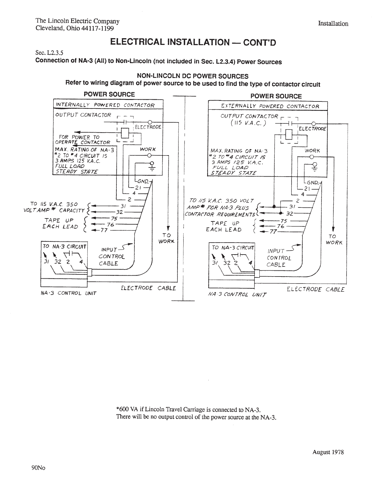
3EC ,!
4HE ,INCOLN %LECTRIC #OMPANY
#LEVELAND /HIO !SSEMBLY AND )NSTALLATION
30%%$&%%$ $25-3
7!2.).'
®
http://www.lincolnelectric.com/knowledge/articles/
content/speedfeeddrums.asp
http://www.lincolnelectric.com/knowledge/articles/
content/drumhandling.asp
Insulated
friction free
eyelet
Speed Feed Drum
Hat
Turntable
Sec. L2.5.10-A (Continued)

Sec. L2.5.10-B
The Lincoln Electric Company
Cleveland, Ohio 44117-1199
Assembly and Installation
SPEED-FEED REELS
®
Sec. L2.5.10-B
Assembly and Installation The Lincoln Electric Company
Cleveland, Ohio 44117-1199
(Continued)
INSTALLATION INSTRUCTIONS
SPEED-FEED REELS
®


G1385
G1387
G1458

L6488
L6489

WIRING DIAGRAMS
L6488-1
A
ELECTRODE TO POWER SOURCE
WORK
517 528 539S
4CR
D.C. METER SHUNT
REED SWITCH ACTUATED
BY WELDING CURRENT
67
593
592
592
539S
582 581
539S
641 642 634
5K
STOP
SWITCH
START
SWITCH
WIRE FEED
SPEED CONTROL
INCH UP
SWITCH
INCH DOWN
SWITCH
576 575
POWER SOURCE
OUTPUT CONTROL
10K
77
AM
517
67
-
+
VM
67
-
+
21
625
532
532
25
TRAVEL
SWITCH
HAND
OFF
AUTO
2532
531A
631
532
32
531
31
53187
FLUX OR
WATER
SOLENOID
WIRE FEED MOTOR
627
539
531
531A
626
541
ARM
531
87
FLUX CONNECTOR
C
B
A
531
87
532
25
531
GND.
GND.GND.
A
B
C
D
539
627
626
A
B
C
D
GND. E
541
539
627
626
GND.
541
A
B
C
D
E
GND.
F
G
H
I
2
4
31
32
75
21
76
77 77
76
75
21
32
31
4
2
MOTOR CONNECTOR
CONTROL CABLE TO
POWER SOURCE
585
510
589
510
532
625
CONTROL POWER
SWITCH
31
67
21
77
76
75
681
689
528
582
581
4
87
32
626
627
539
539S
510
2
541A
541
532
592
562
635
636
637
525
539
528
531A
67
21
TRAVEL
CONNECTOR
1
10
2
3
4
5
6
7
8
9
11
12
VARIABLE VOLTAGE P.C.BD. (NA-3S ONLY)
*
JUMPER CONNECTOR "C"
510A
2
1
10
7
9
12
6
8
11
510
610
631
532
539
541
627
626
*
539
525
539S
593
629
539
525
587
CONTROL P.C.BD.
*
586
1
2
3
4
5
6
7
8
9
250
610
510
525
629
539
636
635
641
642
75
77
1
2
3
4
6
7
8
9
11
12
76
*
75
76
*
1
2
3
4
6
7
9
10
11
12
77
635
584(S)
629
515
539
525
583(S)
75
76
*
1
2
3
4
6
7
9
10
11
12
77
635
584(C)
629
515
539
525
583(C)
5
588
1
4
6
3
2
9
8
575
576
681
634
592
682
510A
*
LOGIC
P.C.BD.
9
8
510A
510A
4
6
528
689
11 582
12 581
2585
3589
5562
1637
7587
10 586
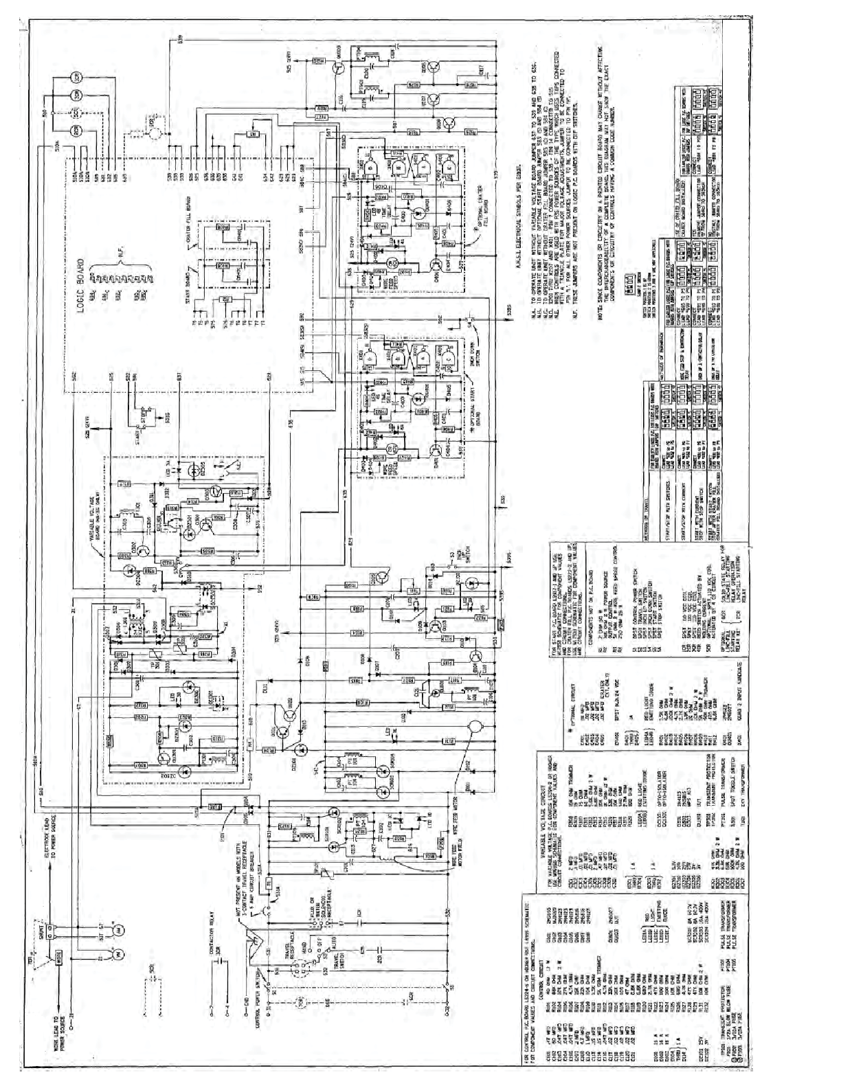
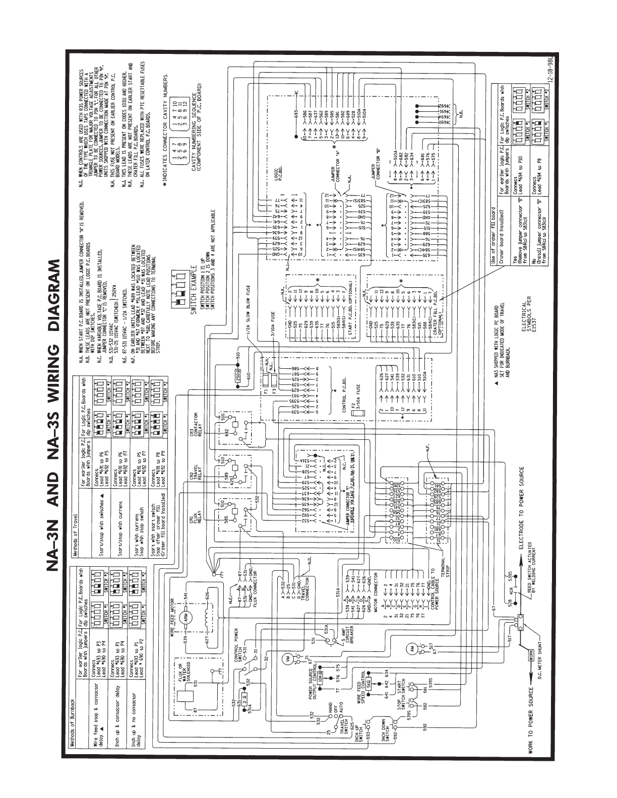
NA-3N AND NA-3S WIRING DIAGRAM
531A
N.E.
N.D.
TERMINAL
STRIP
N.F.
CR1
FLUX
RELAY
CR2
TRAVEL
RELAY
CR3
CONTACTOR
RELAY
N.C.
N.G.
F2
F1
F3
JUMPER
CONNECTOR "A"
JUMPER
CONNECTOR "B"
N.A.
690
694
691
692
693
*
N.B.
WORK TO POWER SOURCE
JUMPER CONNECTOR "C" IS REMOVED.
N.C. WHEN VARIABLE VOLTAGE P.C. BOARD IS INSTALLED,
N.E. 87-531 115VAC - 1/2A SWITCHED.
N.F. ON EARLIER UNITS, LEAD #689 WAS LOCATED BETWEEN
#31 AND #67 (FORMERLY #5), LEAD #510 WAS LOCATED
NEXT TO #681. CAREFULLY NOTE LEAD POSITIONS
BEFORE MAKING ANY CONNECTIONS TO TERMINAL
STRIP.
N.G. WHEN CONTROLS ARE USED WITH R3S POWER SOURCES
OF THE TYPE WHICH USES TAPS CONNECTED WITH A
TRIANGLE PLATE FOR MAJOR VOLTAGE ADJUSTMENTS
JUMPER TO BE CONNECTED TO PIN "L". FOR ALL OTHER
POWER SOURCES, JUMPER TO BE CONNECTED TO PIN "H".
UNITS SHIPPED WITH CONNECTION MADE AT PIN "H".
N.H. THIS FUSE NOT PRESENT ON EARLIER CONTROL P.C.
BOARD MODELS.
N.B. THESE LEADS ARE NOT PRESENT ON LOGIC P.C. BOARDS
WITH DIP SWITCHES.
Methods of Burnback Methods of Travel
Start/stop with switches Lead #691 to P6
Lead #692 to P5
Start/stop with current Lead #691 to P6
Lead #692 to P7
Start with current
Stop with stop switch Lead #691 to P5
Lead #692 to P7
Start with start switch
Stop after crater fill
(Crater fill board installed)
Lead #691 to P8
Lead #692 to P9
For earlier logic P.C.
Boards with jumpers
tcennoCseY
Lead #694 to P10
tcennoCoN
Lead #694 to P8
Wire feed stop & contactor
delay Lead #693 to P3
Lead #690 to P4
Inch up & contactor delay Lead #693 to P1
Lead #690 to P4
Inch up & no contactor
delay Lead #693 to P1
Lead # 690 to P2
Crater board installed?
SWITCH #1
123 4
SWITCH #2
1234
SWITCH #1
123 4
SWITCH #2
1234
For Logic P.C. Boards with
dip switches
(Remove jumper connector "B"
from 584(c) to 583(c))
(Install jumper connector "B"
from 584(c) to 583(c))
For earlier logic P.C.
Boards with jumpers
Connect
Connect
SWITCH #1
123 4
SWITCH #2
123 4
SWITCH #1
123 4
SWITCH #2
123 4
For Logic P.C. Boards with
dip switches
Connect
Connect
SWITCH #1
123 4
SWITCH #2
123 4
SWITCH #1
123 4
SWITCH #2
123 4
N.A. WHEN START P.C. BOARD IS INSTALLED, JUMPER CONNECTOR "A" IS REMOVED.
Use of crater fill board
For earlier logic P.C.
Boards with jumpers
Connect
Connect
SWITCH #1
1234
SWITCH #2
1234
SWITCH #1
1234
SWITCH #2
1234
For Logic P.C. Boards with
dip switches
Connect
SWITCH #1
1234
SWITCH #2
1234
N.D. 531-532 115VAC
531-25 115VAC (SWITCHED)
}
250VA
BETWEEN #87 AND #32 AND LEAD #31 WAS LOCATED
3/10A FUSE
3/10A FUSE
1/2A SLOW BLOW FUSE
N.H.
1234
1
2
3
4
5
6
7
8
9
1
2
3
4
5
6
7
8
9
10
11
12
INDICATES CONNECTOR CAVITY NUMBERS
*
CAVITY NUMBERING SEQUENCE
(COMPONENT SIDE OF P.C. BOARD)
SWITCH EXAMPLE
SWITCH POSITION 1 IS UP
SWITCH POSITION 2 IS DOWN
SWITCH POSITIONS 3 AND 4 ARE NOT APPLICABLE
5 AMP
CIRCUIT
BREAKER
ELECTRICAL
SYMBOLS PER
E1537
NA3 SHIPPED WITH LOGIC PC BOARD
AND BURNBACK.
SET FOR INDICATED MODE OF TRAVEL
588
515
635
539
629
525
584(C)
583(C)
76
77
75
515
635
539
629
525
584(S)
583(S)
76
77
75
11
12
9
8
10
5
6
4
3
7
START P.C.BD. (OPTIONAL)
CRATER FILL P.C.BD.
(OPTIONAL)
*
11
12
9
8
10
5
6
3
4
1
*
7
GND 8GND 8
GND10
N.J.
GND
N.K.
GND 2
N.K.
N.J. THIS LEAD IS PRESENT ON CODES 10311 AND HIGHER.
N.K. THESE LEADS ARE NOT PRESENT ON EARLIER START AND
CRATER FILL P.C. BOARDS.
N.L.
N.L. ALL FUSES WERE REPLACED WITH PTC RESETTABLE FUSES
ON LATER CONTROL P.C. BOARDS.
DOOR
SUBPANEL
682
510
24
1
2
3
4
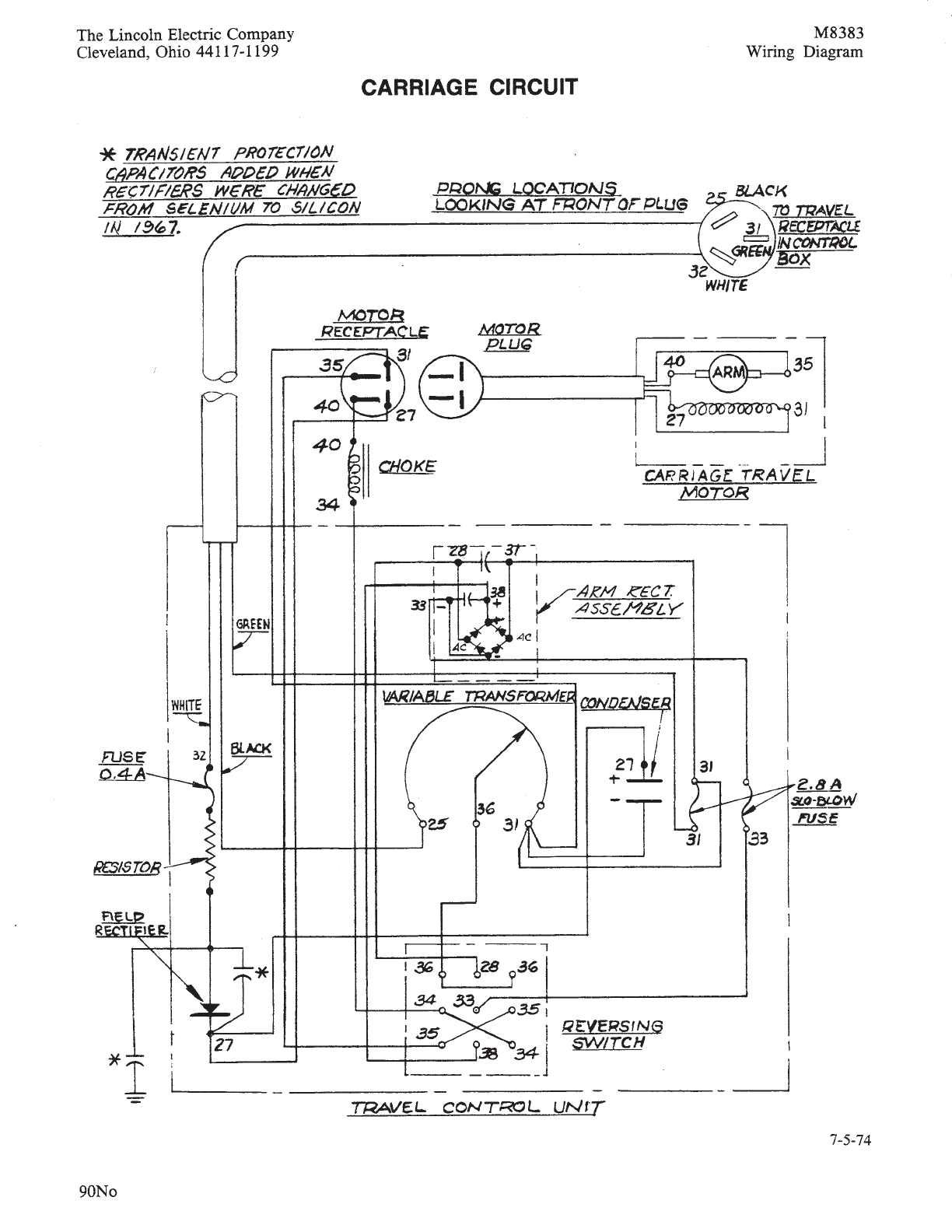
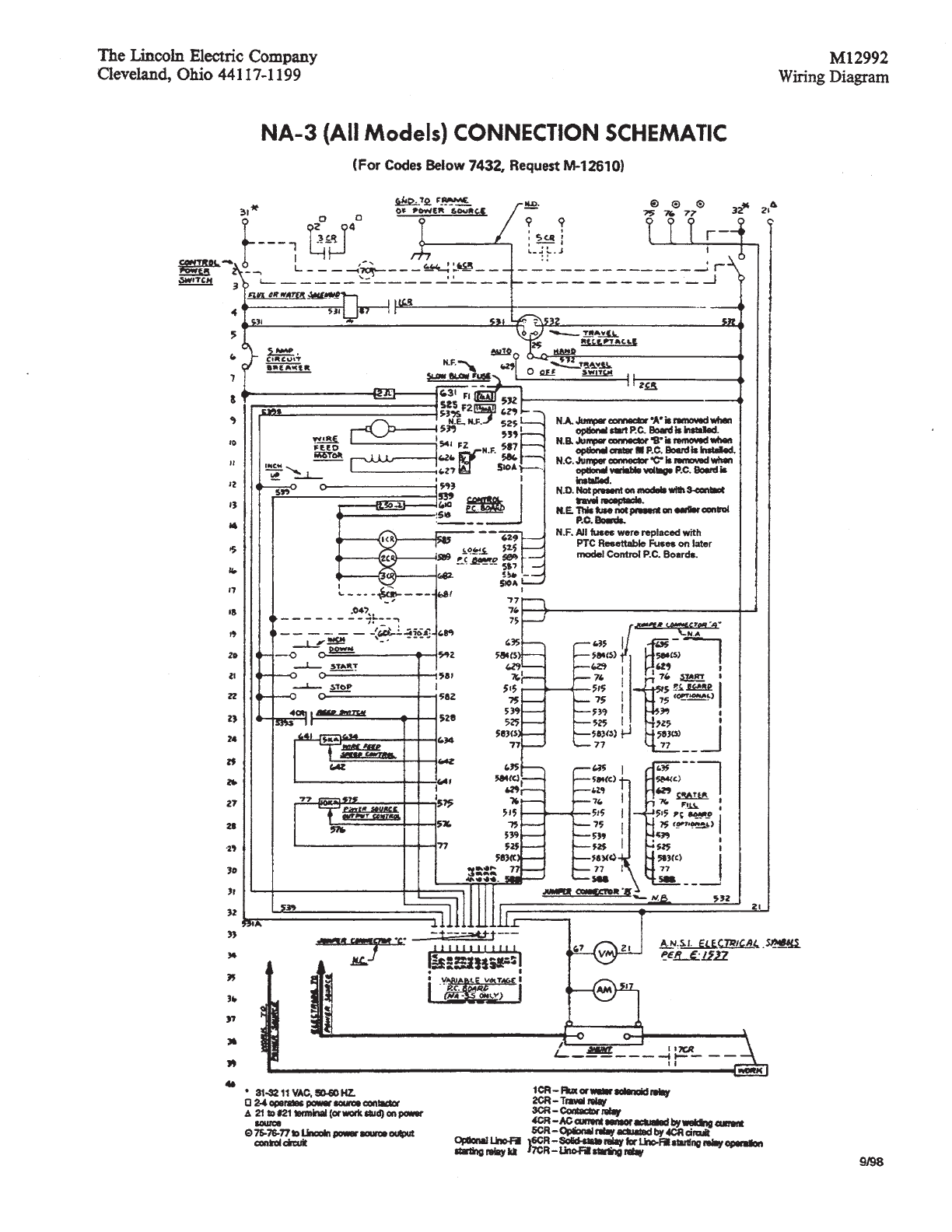
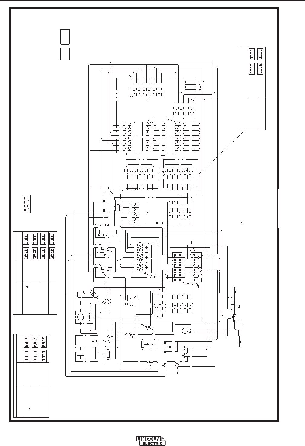
NOTE: This diagram is for reference only. It may not be accurate for all machines covered by this manual. The specific diagram for a particular code is pasted inside
the machine on one of the enclosure panels. If the diagram is illegible, write to the Service Department for a replacement. Give the equipment code number.
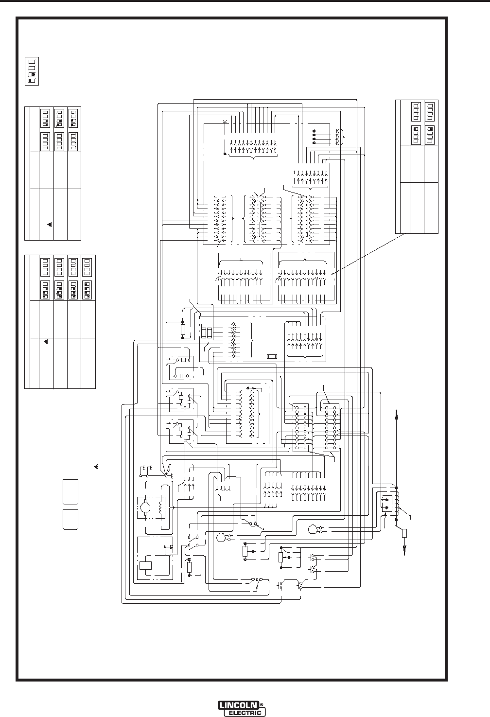
WIRING DIAGRAMS
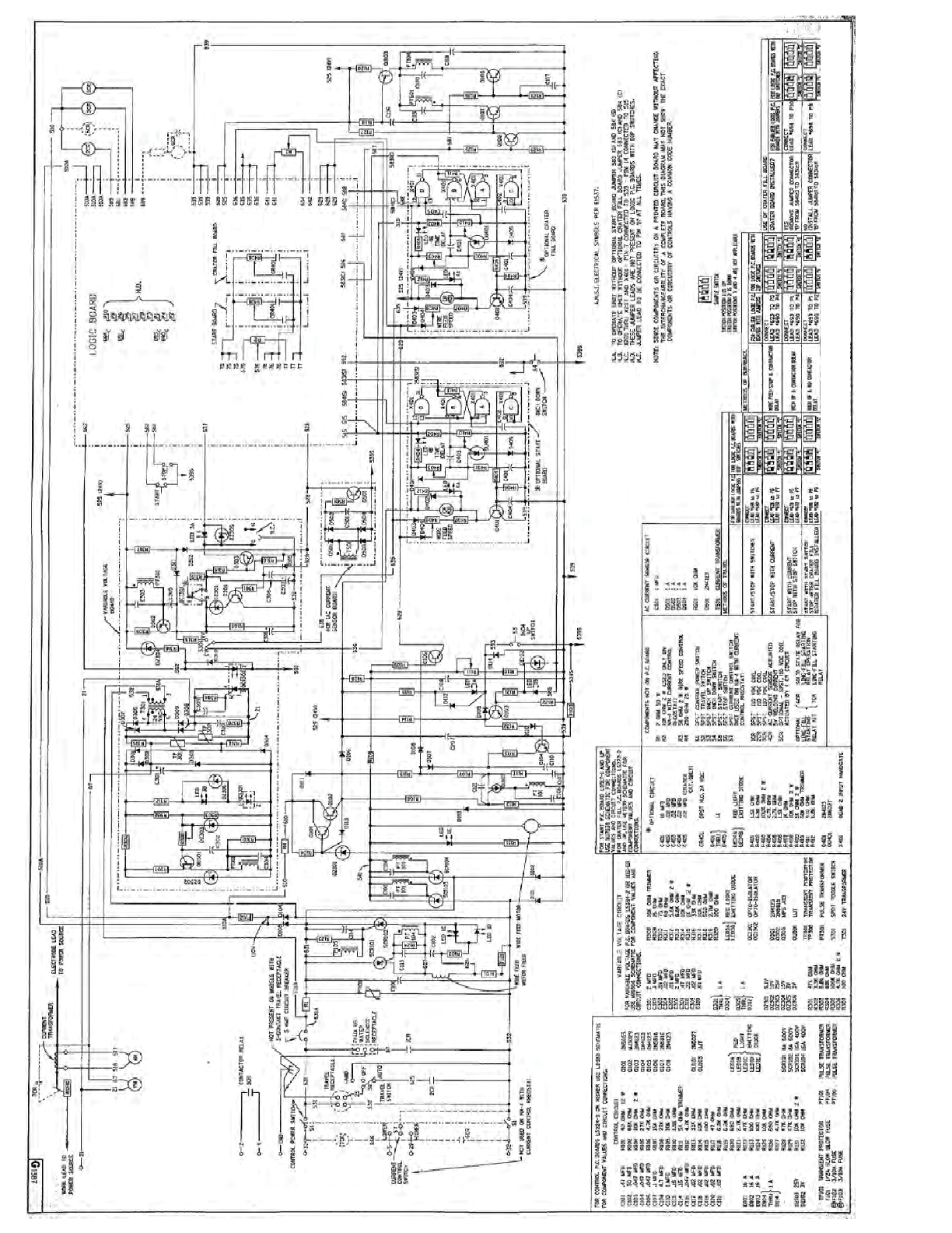
L6489-1
A
ELECTRODE TO POWER SOURCE
WORK
517 67
593
592
592
539S
582 581
539S
634 642 641
5K
STOP
SWITCH
START
SWITCH
WIRE FEED
SPEED CONTROL
INCH UP
SWITCH
INCH DOWN
SWITCH
576 575
POWER SOURCE
OUTPUT CONTROL
10K
77
AM
517
-
+
VM
67
-
+
21
625
532
532
25
TRAVEL
SWITCH
HAND
OFF
AUTO
2532
531A
631
532
32
531
31
53187
FLUX OR
WATER
SOLENOID
WIRE FEED MOTOR
627
539
531
531A
626
541
ARM
531
87
FLUX CONNECTOR
C
B
A
531
87
532
25
531
GND.
GND.GND.
A
B
C
D
539
627
626
A
B
C
D
GND. E
541
539
627
626
GND.
541
A
B
C
D
E
GND.
F
G
H
I
2
4
31
32
75
21
76
77 77
76
75
21
32
31
4
2
MOTOR CONNECTOR
CONTROL CABLE TO
POWER SOURCE
585
510
589
510
682
510
532
625
CONTROL POWER
SWITCH
31
67
21
77
76
75
681
689
528
582
581
4
87
32
626
627
539
539S
510
2
541A
541
532
592
562
635
636
637
525
539
528
531A
67
21
TRAVEL
CONNECTOR
24
1
10
2
3
4
5
6
7
8
9
11
12
*
510A
2
1
10
7
9
12
6
8
11
510
610
631
532
539
541
627
626
*
539
525
539S
593
629
539
525
587
CONTROL P.C.BD.
*
586
1
2
3
4
5
6
7
8
9
250
610
510
525
629
539
636
635
641
642
75
77
1
2
3
4
6
7
8
9
11
12
76
*
75
76
*
1
2
3
4
6
7
9
10
11
12
77
635
584(S)
629
515
539
525
583(S)
75
76
*
1
2
3
4
6
7
9
10
11
12
77
635
584(C)
629
515
539
525
583(C)
5
588
1
4
6
3
2
9
8
575
576
681
634
592
682
510A
*
LOGIC
P.C.BD.
9
8
510A
510A
4
6
528
689
11 582
12 581
2 585
3 589
5562
1637
7587
10 586
531A
N.D.
TERMINAL
STRIP
N.E.
CR1
FLUX
RELAY
CR2
TRAVEL
RELAY
CR3
CONTACTOR
RELAY
N.F.
F2
F1
F3
N.G.
JUMPER
CONNECTOR "A"
JUMPER
CONNECTOR "B"
N.A.
690
694
691
692
693
*
N.B.
WORK TO POWER SOURCE
N.D. 87-531 115VAC - 1/2A SWITCHED.
N.G. THIS FUSE NOT PRESENT ON EARLIER CONTROL P.C.
BOARD MODELS.
N.B. THESE LEADS ARE NOT PRESENT ON LOGIC P.C. BOARDS
WITH DIP SWITCHES.
Methods of BurnbackMethods of Travel
Start/stop with switches Lead #691 to P6
Lead #692 to P5
Start/stop with current Lead #691 to P6
Lead #692 to P7
Start with current
Stop with stop switch Lead #691 to P5
Lead #692 to P7
Start with start switch
Stop after crater fill
(Crater fill board installed)
Lead #691 to P8
Lead #692 to P9
For earlier logic P.C.
Boards with jumpers
tcennoCseY
Lead #694 to P10
tcennoCoN
Lead #694 to P8
Wire feed stop & contactor
delay Lead #693 to P3
Lead #690 to P4
Inch up & contactor delay Lead #693 to P1
Lead #690 to P4
Inch up & no contactor
delay Lead #693 to P1
Lead #690 to P2
Crater board installed?
SWITCH #1
1234
SWITCH #2
1234
SWITCH #1
1234
SWITCH #2
1234
For Logic P.C. Boards with
dip switches
(Remove jumper connector "B"
from 584(c) to 583(c))
(Install jumper connector "B"
from 584(c) to 583(c))
For earlier logic P.C.
Boards with jumpers
Connect
Connect
SWITCH #1
123 4
SWITCH #2
123 4
SWITCH #1
123 4
SWITCH #2
123 4
For Logic P.C. Boards with
dip switches
Connect
Connect
SWITCH #1
123 4
SWITCH #2
123 4
SWITCH #1
123 4
SWITCH #2
123 4
N.A. WHEN START P.C. BOARD IS INSTALLED, JUMPER CONNECTOR "A" IS REMOVED.
Use of crater fill board
For earlier logic P.C.
Boards with jumpers
Connect
Connect
SWITCH #1
123 4
SWITCH #2
1234
SWITCH #1
123 4
SWITCH #2
1234
For Logic P.C. Boards with
dip switches
Connect
SWITCH #1
123 4
SWITCH #2
1234
5641
N.F. JUMPER LEAD TO BE CONNECTED TO PIN "H" AT ALL TIMES.
UNIT SHIPPED WITH LEAD IN THIS POSITION.
1/2A SLOW BLOW FUSE
3/10A FUSE
3/10A FUSE
641
518
N.C.
11
22
33
44 1
2
3
4
CURRENT TRANSFORMER
518 539S528
CR4
1
2
3
4
5
6
7
8
9
1
2
3
4
5
6
7
8
9
10
11
12
INDICATES CONNECTOR CAVITY NUMBERS
*
CAVITY NUMBERING SEQUENCE
(COMPONENT SIDE OF P.C. BOARD)
NA-4 SHIPPED WITH LOGIC P.C. BOARD
SET FOR INDICATED MODE OF TRAVEL
AND BURNBACK.
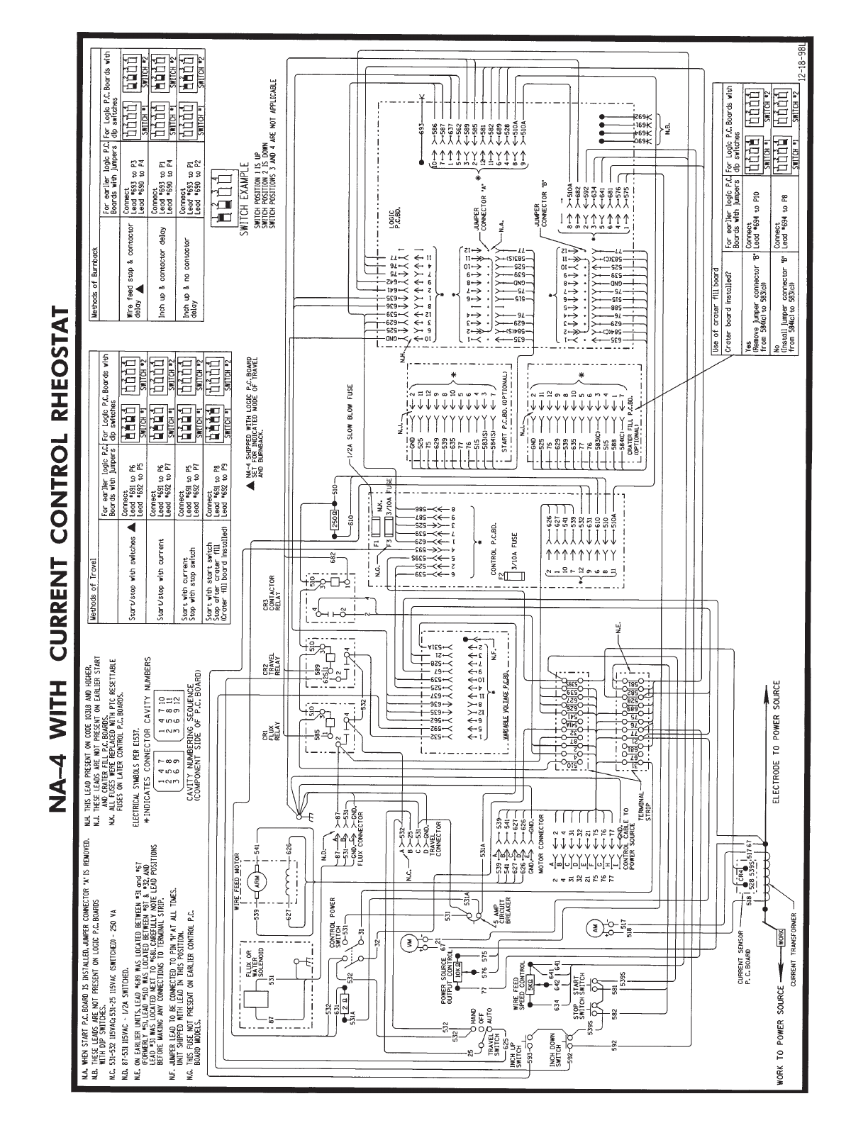
NA-4 WITH CURRENT CONTROL RHEOSTAT
ELECTRICAL SYMBOLS PER E1537.
VARIABLE VOLTAGE P.C.BD.
N.C. 531-532 115VAC; 531-25 115VAC (SWITCHED) - 250 VA
5 AMP
CIRCUIT
BREAKER
CURRENT SENSOR
P. C. BOARD
588
515
635
539
629
525
584(C)
583(C)
76
77
75
515
635
539
629
525
584(S)
583(S)
76
77
75
11
12
9
8
10
5
6
4
3
7
START P.C.BD. (OPTIONAL)
CRATER FILL P.C.BD.
(OPTIONAL)
*
11
12
9
8
10
5
6
3
4
1
*
7
N.E. ON EARLIER UNITS, LEAD #689 WAS LOCATED BETWEEN #31 and #67
(FORMERLY #5), LEAD #510 WAS LOCATED BETWEEN #87 & #32, AND
LEAD #31 WAS LOCATED NEXT TO #681. CAREFULLY NOTE LEAD POSITIONS
BEFORE MAKING ANY CONNECTIONS TO TERMINAL STRIP.
GND
539
8GND 8
GND10
GND 2
N.J.
GND 2
N.J. N.H.
N.H. THIS LEAD PRESENT ON CODE 10318 AND HIGHER.
N.K.
N.J. THESE LEADS ARE NOT PRESENT ON EARLIER START
AND CRATER FILL P.C. BOARDS.
N.K. ALL FUSES WERE REPLACED WITH PTC RESETTABLE
FUSES ON LATER CONTROL P.C. BOARDS.
DOOR
SUBPANEL
1234
SWITCH EXAMPLE
SWITCH POSITION 1 IS UP
SWITCH POSITION 2 IS DOWN
SWITCH POSITIONS 3 AND 4 ARE NOT APPLICABLE
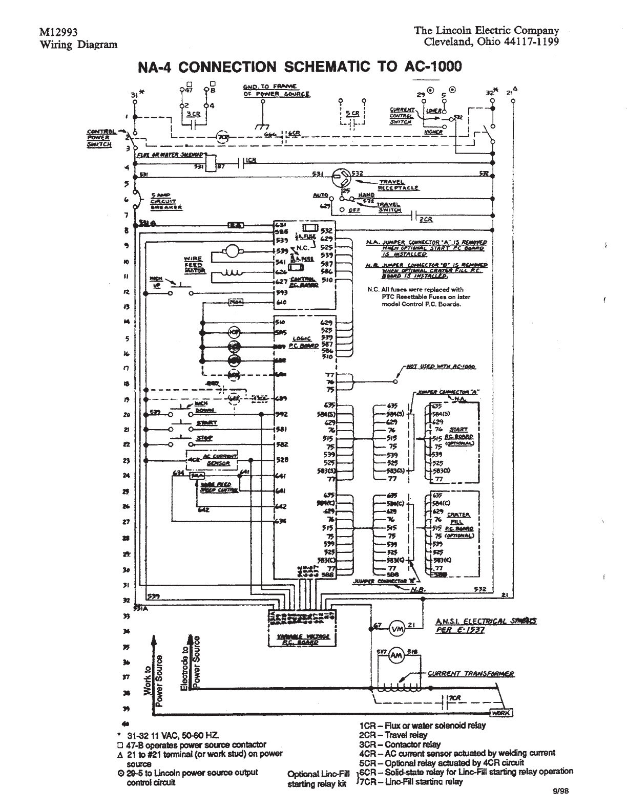
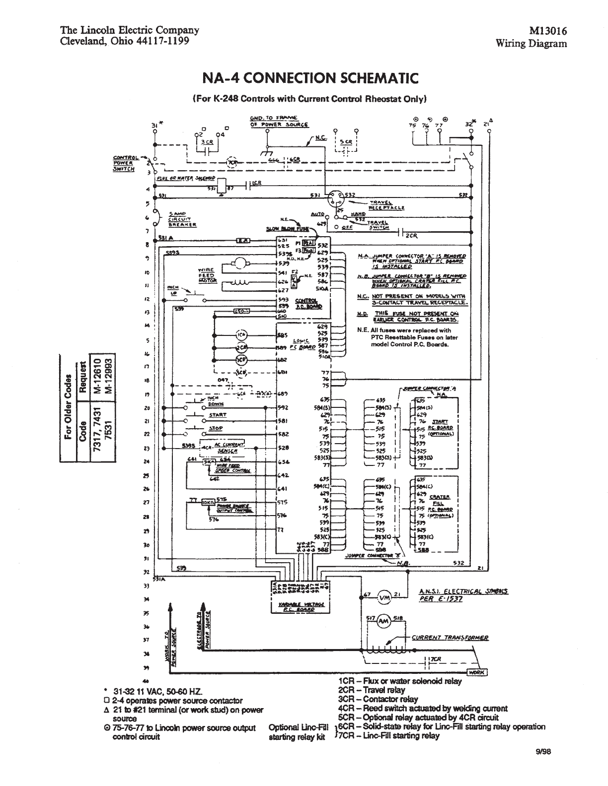
NOTE: This diagram is for reference only. It may not be accurate for all machines covered by this manual. The specific diagram for a particular code is pasted inside
the machine on one of the enclosure panels. If the diagram is illegible, write to the Service Department for a replacement. Give the equipment code number.