Linear Boiler Users Manual
Boiler to the manual 16112cc4-e00f-4031-b587-ddbe01c6b8c3
2015-02-02
: Linear Linear-Boiler-Users-Manual-435928 linear-boiler-users-manual-435928 linear pdf
Open the PDF directly: View PDF ![]() .
.
Page Count: 28

PAGE 1
BIASI B/40
LINEAR
6-12 SECTION
REV. H
Please Read Instructions Carefully
Save for Future Reference
Manufactured by:
Manufactured by:Manufactured by:
Manufactured by:
Biasi S.p.A.
Biasi S.p.A.Biasi S.p.A.
Biasi S.p.A.
Verona, Italy
Verona, ItalyVerona, Italy
Verona, Italy
Distributed By:
Distributed By:Distributed By:
Distributed By:
QHT
QHTQHT
QHT
QUINCY HYDRONIC TECH
QUINCY HYDRONIC TECHQUINCY HYDRONIC TECH
QUINCY HYDRONIC TECHNOLOGY
NOLOGYNOLOGY
NOLOGY, INC.
, INC., INC.
, INC.
3560 LAFAYETTE RD
3560 LAFAYETTE RD3560 LAFAYETTE RD
3560 LAFAYETTE RD
PORTSMOUTH, NH 0380
PORTSMOUTH, NH 0380PORTSMOUTH, NH 0380
PORTSMOUTH, NH 03801
11
1
PHONE: 603
PHONE: 603PHONE: 603
PHONE: 603-
--
-334
334334
334-
--
-6400
64006400
6400
FAX: 603
FAX: 603FAX: 603
FAX: 603-
--
-334
334334
334-
--
-6401
64016401
6401
Boiler Manual And Installation
Instructions for Atmospheric Venting
LINEAR
BOILER
If the information in this manual is not followed
exactly, a fire explosion may result causing property
damage, personal injury or loss of life.
WARNING
WHAT TO DO IF YOU SMELL GAS
• Do not try to light any appliance
• Do not touch any electric switch; do not use any
phone in your building
• Immediately call your gas supplier from another
location. Follow the gas supplier’s instructions.
• If you can not reach your gas supplier call the
fire department
DANGER

BIASI B/40
PAGE 2
Dear Customer:
Thank you for buying a Linear commercial boiler.
The Linear is a cast iron, oil or gas fired hot water boiler, using the famous 3-pass design. The
boiler is simple, rugged and engineered for maximum heating efficiency.
We realize that it is not possible to answer all questions about the Linear series boiler in this
manual. Reading this installation manual does not make the reader an expert in all aspects of
installation and operation, and does not replace the need for a qualified, licensed heating
contractor. We urge you to contact your installing contractor or distributor if you are in question
about any aspect of your boiler's performance. Our main concern is that you are satisfied with
your boiler and its performance. We require that your contractor complete efficiency tests
using instruments.
The controls and accessories listed in this manual are intended to serve as guidelines rather than
specific recommendations. We realize that other makes and models of such devices are
available and can be used as successfully as those we specify. The installing contractor is the
best judge of a system's specific requirements, as well as the local availability of certain makes
and models of controls and accessories. The preceding does not apply, however, to the
equipment that comes with every boiler, such as the overheat control (L4006E) and pressure
relief valve. The installation of the specific devices supplied with every boiler is absolutely
necessary to the safe operation of the boiler and protection of the heating system.
This Linear boiler has a limited warranty, a copy of which is provided with the boiler. Please
be sure to return the warranty registration card as the warranty will be void without your boiler's
serial numbers, date of installation and the name of your installer being on record in our files.
Thank you for purchasing our B-40 Linear series boiler. If you have questions or comments,
please don't hesitate to contact us immediately. Our goal is 100% customer satisfaction.

PAGE 3
BIASI B/40
BIASI B-40 Linear Series Section Page
Important Information 1 4
General Information 2 6
Codes and Regulations 3 6
Combustion Air Supply 4 7
Boiler Location 5 7
Boiler Block Assembly 6 8
Boiler Trim Kit Installation 7 8
Boiler Tapping Diagram - 9
Burner Set-up 8 10
Gas Piping 9 12
Breeching and Chimney 10 14
Piping 11 15
Boiler Jacket Assembly 12 17
Boiler Jacket Explosion Diagram - 18
Wiring 13 19
B-40 Control Panel Wiring 20-23
Commissioning 14 24
Maintenance 15 24
Installer Notes 16 25
TABLE OF CONTENTS

BIASI B/40
PAGE 4
IMPORTANT INFORMATION
Please read this page carefully.
ALL BOILERS MUST BE INSTALLED IN ACCORDANCE WITH NATIONAL, STATE AND
LOCAL PLUMBING, HEATING AND ELECTRICAL CODES AND ORDINANCES, AS WELL AS
THE REGULATIONS OF THE SERVING ELECTRICAL, WATER AND GAS UTILITIES.
All systems should be designed by competent contractors, and only persons knowledgeable in the
layout and installation of heating systems should attempt the installation of any boiler.
It is the responsibility of the installing contractor to see that all controls are correctly installed and
operating properly when the installation is completed.
Do not burn volatile garbage, gasoline, naphtha or other flammable liquids other than No. 2 fuel
oil. All flammable liquids (especially gasoline), chemicals, rags, paper, wood scraps, debris, etc.,
should be kept away from the boiler at all times. Keep the boiler area clean and free of all fire
hazards.
Please read the literature and warranties supplied by the manufacturers of the various accessory
equipment. This equipment is warranted by the respective manufacturers, not by Quincy Hydronic
Technologies, Inc. Each piece of equipment must be installed and used according to the
recommendations of the manufacturer.
This Linear boiler has a limited lifetime warranty, a copy of which is printed on the back page of this
manual.

PAGE 5
BIASI B/40
Any appliance that burns natural gas, propane gas, fuel oil, wood or coal is capable of producing
carbon monoxide (CO). Carbon Monoxide (CO) is a gas which is odorless, colorless and tasteless but
is very toxic.
If your BIASI B-40 boiler is not working properly, or is not vented properly, dangerous levels of CO
may accumulate. CO is lighter than air and thus may travel throughout the building. BRIEF
EXPOSURE TO HIGH CONCENTRATIONS OF CO, OR PROLONGED EXPOSURE TO
LESSER AMOUNTS OF CO MAY RESULT IN CARBON MONOXIDE POISONING.
EXPOSURE CAN BE FATAL AND EXPOSURE TO HIGH CONCENTRATIONS MAY
RESULT IN THE SUDDEN ONSET OF SYMPTOMS INCLUDING UNCONSCIOUSNESS.
Symptoms of CO poisoning include the following:
Dizziness Vision problems Shortness of breath
Headache Loss of muscle control Unclear thinking
Nausea Weakness Unconsciousness
The symptoms of CO poisoning are often confused with those of influenza, and the highest incidence
of poisoning occurs at the onset of cold weather or during flu season. A victim may not experience
any symptoms , only one symptom, or a few symptoms. Suspect the presence of carbon monoxide if
symptoms tend to disappear when you leave your home.
The following signs may indicate the presence of carbon monoxide:
* Hot gasses from appliance, venting system, pipes or chimney,
escaping into the living space.
* Flames coming out around the appliance.
* Yellow colored flames in the appliance.
* Stale or smelly air.
* The presence of soot or carbon in or around the appliance.
* Very high unexplained humidity inside the building.
If any of the symptoms of CO occur, or if any of the signs of carbon monoxide are present, VACATE
THE PREMISES IMMEDIATELY AND CONTACT A QUALIFIED HEATING SERVICE
COMPANY OR THE GAS COMPANY AND THE FIRE DEPARTMENT.
To reduce the risk of CO poisoning, have your heating system "tuned up" by a licensed heating
contractor or the gas company - preferably before each heating season. Also have the service
company check your chimney or vent pipes for blockage.
The building should be adequately ventilated, particularly if you have tightly insulated your home.
ONLY QUALIFIED, LICENSED SERVICE CONTRACTORS SHOULD PERFORM WORK
ON YOUR BIASI B-40 BOILER.
WARNING
BIASI B/40
PAGE 6
The Linear series are wet base design, sectional, cast-iron boilers for forced hot water heating
systems. The Linear boilers are designed for firing with oil and deliver high efficiencies through
unique design and construction.
The Linear series boilers are shipped from the factory in assembled blocks and each boiler can
range from 6 to 12 sections. The sections can then be disassembled before delivery to the jobsite by
QHT and then field assembled. The boiler jacket, burner and controls are packed separately for
shipping.
Note: All equipment should be inspected upon delivery, and any damage or shortage should
be reported immediately.
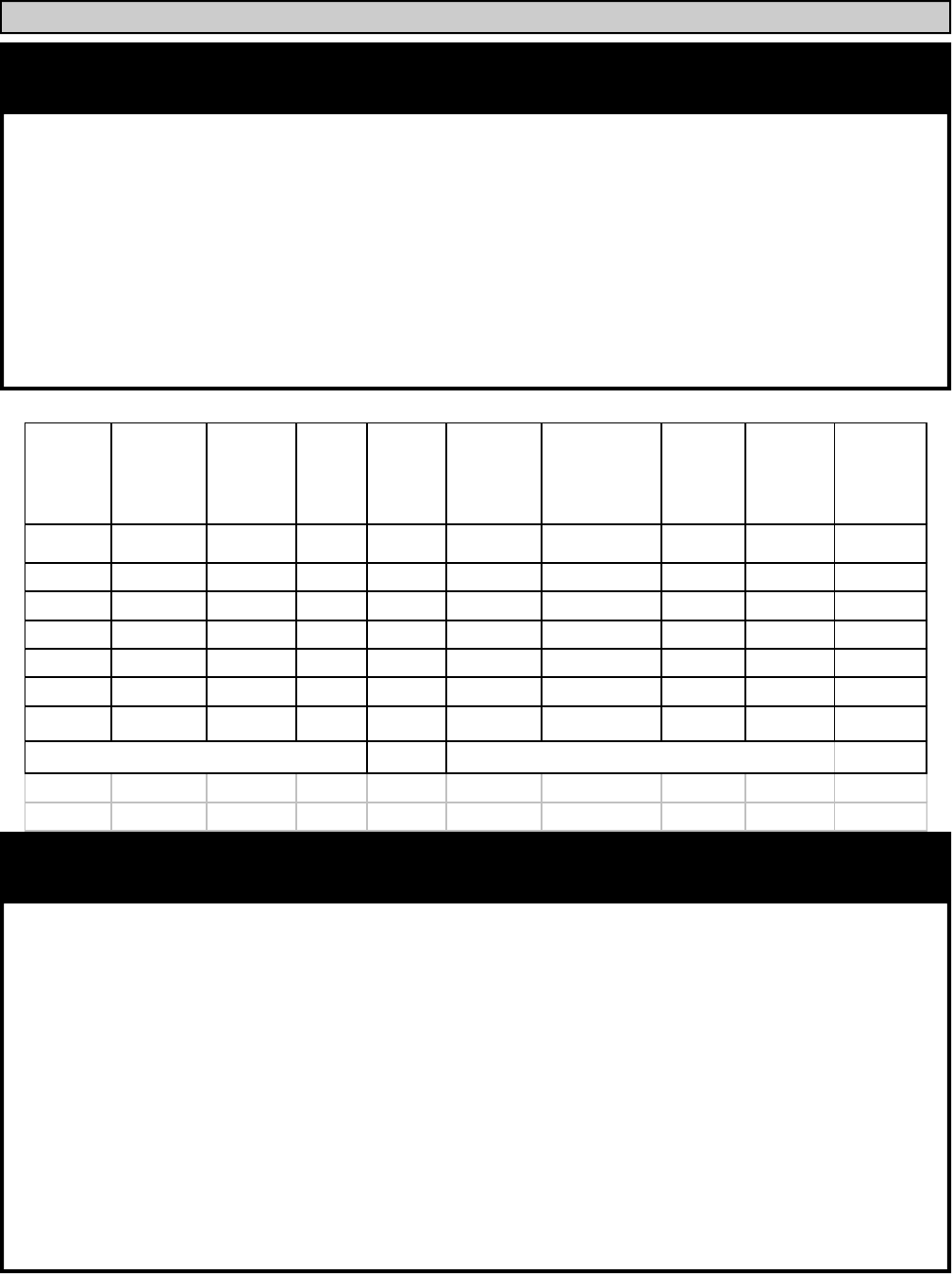
Boiler
Model
Number
Number of
Sections
Heating
Capacity
Input
Oil
G.P.H.
Input
Gas
MBH
Net Output
MBH Efficiency %
Water
Content
Gals.
Length
(L) inches
Weight
(LBS)
B40/6 6 265 2.20 308 230 86.0 17 34.8 902
B40/7 7 352 2.90 406 305 86.7 20 39.5 1023
B40/8 8 437 3.60 504 380 86.8 23 44.4 1144
B40/9 9 524 4.30 602 456 87.0 26 49.2 1265
B40/10 10 610 5.00 700 532 87.2 28 53.9 1386
B40/11 11 696 5.70 798 607 87.2 31 58.8 1507
B40/12 12 783 6.40 896 684 87.4 34 63.8 1628
Maximum Water Working Pressure 72 psi Maximum Relief Valve is 50 psi @ 900 MBH
2. General Information:
Installation of the boiler, burner, oil tank and related equipment must conform to national,
state and local regulating agencies and codes applicable to the installation of the equipment. In the
absence of local requirements, the following codes apply:
•
••
•
ANSI/NFPA - #31 Installation of Oil Burning Equipment
•
••
•
ANSI/NFPA - #70 National Electric Code
•
••
•
ANSI/NFPA - #211 Chimneys and Vents
The above codes are available from:
National Fire Protection Association (NFPA)
Battery March Park
Quincy, Massachusetts, 02269
3. Conforming to Codes and Regulations:
PAGE 7
BIASI B/40
Locate the boiler to provide sufficient clearance for inspection, servicing and maintenance.
Minimum clearance to construction or combustible materials shouldn't be less than six (6) inches from
the top, sides and rear of unit, and eighteen (18) inches from the flue pipe in any direction. Front
clearance should be at least twenty four (24) inches. When choosing a location for the boiler, take
into consideration the 12” supply manifold on the back of the boiler. Adequate space must be given to
pipe the manifold in and for the smoke pipe to clear the manifold. Greater distances for ease of access
should supersede fire protection clearances. The boiler must be located on a non-combustible floor. A
smooth, level concrete floor is recommended. Locate the boiler as close as possible to the chimney. If
boiler is installed on combustible flooring, consult local authorities for proper method of covering
floor. The boiler must not be installed on carpeting.
Caution: Do not store or use flammable materials, chemicals or flammable liquids,
especially gasoline, in the vicinity of this heating appliance.
The boiler location must provide air for proper combustion and ventilation of the surrounding
area. To burn efficiently, oil requires 30 CFM/GAL. In general, boiler rooms should incorporate two
(2) permanent air supply openings, one commencing within 12 inches of the ceiling, and one
commencing within 12 inches of the floor. These openings
should freely communicate with the
outdoors.
OUTSIDE AIR: When combustion air is supplied directly through an outside door or wall,
each opening shall have a free area of one square inch per 4,000 BTUH input for the total input of all
the appliances in the enclosure.
INSIDE AIR: When combustion air is supplied from inside the building, each opening shall
have a free area of one square inch per 1,000 BTUH input for the total of all appliances in the
enclosure. In no case shall the openings be less than 105 square inches each.
In both cases, check manufacturers ratings for louver net free area, and correct for screen
resistance to net free area.
If the boiler is to be installed where the operation of exhaust fans, attic fans, kitchen
ventilation systems, clothes dryers or fireplaces may create severe negative vent pressures causing
unsatisfactory combustion and venting, special provisions should be made for additional make-up air
to supply the other air requirements. If building is of tight construction, combustion air requirements
may not be met and combustion air ducts from outside may be necessary. Please refer to NFPA No.
31.
Do not install the boiler until the proper combustion air has been arranged
4. Combustion Air Supply:
5. Boiler Location:
BIASI B/40
PAGE 8
All Linear series boilers are shipped either as an assembled boiler block or a knock-down
boiler block. If the block came unassembled, or if the assembled block needs to be split for installa-
tion purposes, please read the following:
To assemble split blocks, move the sections into a line facing each other. Sections may be slid
along boards placed underneath the sections. Inspect nipple ports for damage or burrs. Remove any
burrs by brushing the port very lightly. Wipe the push nipples and nipple ports with a clean cloth.
Apply a film of nipple compound to both the nipple and port. Install the nipple in the port and then
seal it by hitting it with a rubber mallet. Apply section sealant to one section only and slide sections
together. If the boiler came in sections, you will want to draw the sections together 2 or three at a time
to insure that the blocks are coming together properly. Install the four draw rods and draw the sections
together evenly (measure with yardstick). The longer draw rods should be installed on the top of the
boiler. The shorter draw rods are installed on the bottom of the boiler. The bottom draw rods should
not extend past the front section. Draw the sections together until sections make iron-to-iron contact
at a point around the top and bottom ports of each section. Check to insure that the combustion cham-
ber is sealed using a flash light or other lighting device. Place the flashlight into the combustion
chamber and look for light on the floor or surrounding walls (this is best done in a dark room). If light
appears out of the boiler use a high temperature caulk to fill in the gaps between the block sections.
DO NOT OVER TIGHTEN DRAW RODS
6. Boiler Block Assembly:
The BIASI B-40 Boiler Trim Kit includes the following components.
The above mechanical components should be installed following the diagram of the boiler
tappings on the following page. The installation of the above wiring components (wiring harness) will
be described in the wiring portion of this installation manual.
7. Installation of Boiler Trim Components:
1— Honeywell L4006 E Aquastat
1— 3/4” X 3” Nipple
1— 3/4” Elbow
1— 50 PSI Pressure Relief Valve
1— Immersion Well
1— Four Wire Molex Wire Harness
1— Pressure/Temperature Gauge
1— 3/4” Boiler Drain
1— 1/4”X3/4” Bushing
1— 2 1/2” MPT Supply Manifold
1— 2 1/2” MPT Return Manifold
PAGE 9
BIASI B/40
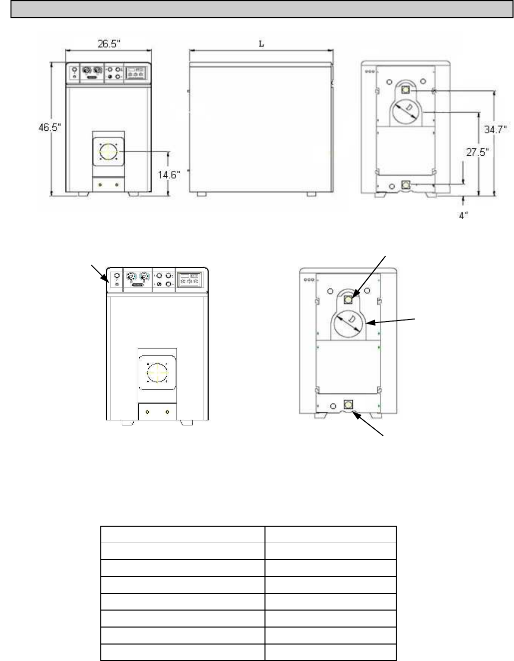
Figure 1:Diagram illustrating the location and function of the front and rear boiler tappings.
Boiler Model Length (L)
B-40/6 34.8”
B-40/7 39.5”
B-40/8 44.5"
B-40/9 49.2"
B-4/10 53.9"
B-4/11 58.8"
B-4/12 63.9"
2.5” MPT Return
2.5” MPT Supply
8” Breech
Control Panel with
operating aquastats
BIASI B/40
PAGE 10
Good, reliable operation with a minimum of service starts with attention to the small details:
1. Setting the nozzle position and electrodes "by the book" using the manufacturer's gauges.
2. Installing a quality micron filter at the burner.
3. Making careful/tight flare connections without couplings on oil suction line.
4. Checking fuel pump pressure.
5. Checking draft at the breeching to insure it is adequate to overcome flue gas resistance.
6. Setting the air band properly with well maintained instruments. A good target is 11% to 12.5% of (CO
2
) or 6.5%
to 3.8% of (O
2
).
Note: Oil and Gas burners on B40-series boilers cannot be properly commissioned
without instruments and gauges.
The following information applies only to the BIASI B-40 series boilers at a maximum output
for power venters or lined chimneys only.
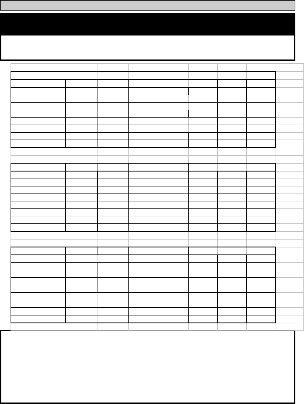
8. Burner Setup:
BURNER MANUFACTURER Heatwise
Boiler Model B-406 B-407 B-408 B-409 B-410 B-411 B-412
Burner Model P2-KA P2-K P2-K DE-10 DE-10 DE-10 DE-10
Firing Rate 2.2 GPH 2.8 GPH 3.5 GPH 4.25 GPH 5.0 GPH 5.7 GPH 6.4 GPH
Insertion Depth FULL FULL FULL FULL FULL FULL FULL
Nozzle 2.00 X 45 2.25 X 60 2.75 X 60 3.25 X 60 3.75 X 60 4.5 X 45 5.50 X 45
Spray Pattern solid solid solid solid solid solid solid
Pump Pressure 140 psi 170 psi 175 psi 175 psi 175 psi 160 psi 140 psi
Head Position 12 16 18 1 1.5 2 2.5
Air Setting 11.50 15.00 18.00 3.5 4.5 5.5 6.75
BURNER MANUFACTURER Riello
Boiler Model B-406 B-407 B-408 B-409 B-410 B-411 B-412
Burner Model F-10 F-10 F-15 F-15 F-15 F-20 F-20
Firing Rate 2.4 GPH 2.6 GPH 3.3 GPH 4.0 GPH 4.6 GPH 5.3 GPH 5.9 GPH
Insertion Depth 4.5" 4.5" 4.5" 4.5" 4.5" 4.5" 4.5"
Nozzle 2.00X60 2.00X60 2.50X60 3.00X60 3.50X60 4.0X60 4.5X60
Spray Pattern B B B B B B B
Pump Pressure 145 PSI 175 PSI 175 PSI 175 PSI 175 PSI 175 PSI 175 PSI
Turbulator 3.75 4.5 1.8 2.1 2.8 3.1 5
Air Gate 5 6 3 4 5.5 4 6
BURNER MANUFACTURER Beckett
Boiler Model B-407 B-407 B-408 B-409 B-410 B-411 B-412
Burner Model CF 375 CF 375 CF 500 CF 500 CF 800 CF 800 CF 800
Firing Rate 2.1 GPH 2.7 GPH 3.2 GPH 3.7 GPH 4.3 GPH 4.8 GPH 5.3 GPH
Insertion Depth 4.5" 4.5" 4.5" 4.5" 4.5" 4.5" 4.5"
Nozzle 1.75X60 2.00X45 2.75X45 2.75X45 3.25X45 4.0X30 4.0X30
Spray Pattern ES hollow solid solid solid solid solid
Pump Pressure 140 psi 180 psi 140 psi 180 psi 175 psi 145 psi 180 psi
Head Type
Head Position 0 2 3 4.5 3 3 4.5
Air Setting 9/0 3/1 7/0 10/0 7/0 8/0 10/2
PAGE 11
BIASI B/40
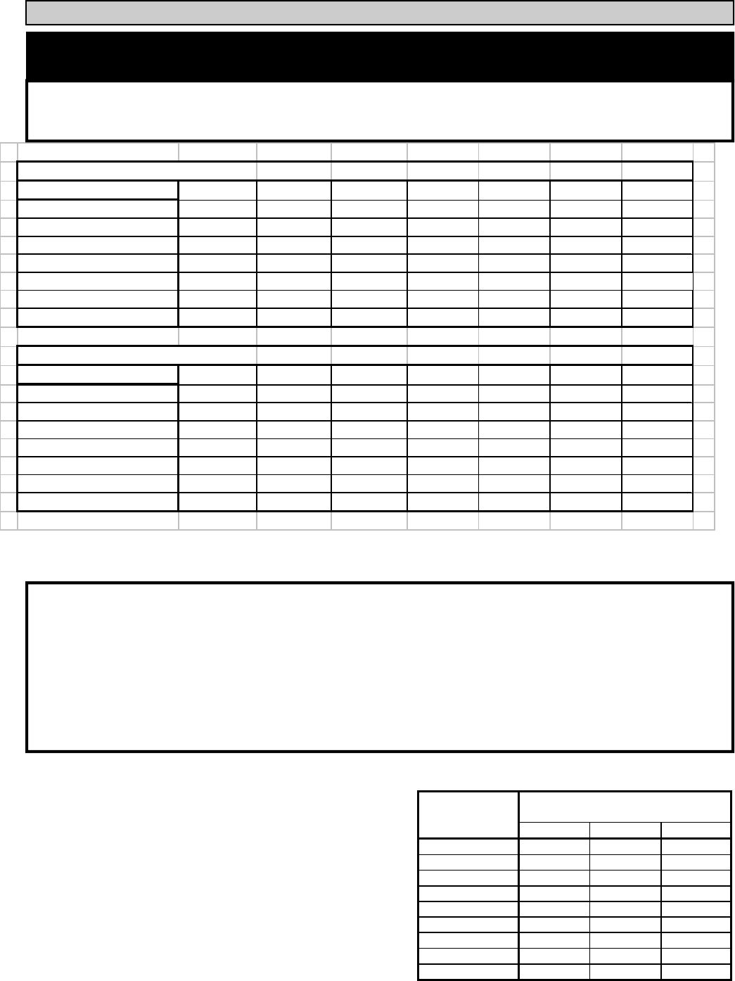
BURNER MANUFACTURER Heat Wise
Boiler Model B-406 B-407 B-408 B-409 B-410 B-411 B-412
Burner Model SU-3 SU-3 SU-4 SU-5 SU-5 SU-6 SU-6
Fuel Natural Natural Natural Natural Natural Natural Natural
Input 315 420 499 577 672 847 954
Min. Gas Inlet Size 1" 1" 1" 1" 1" 1" 1-1/4"
Manifold in w.c. 1.95" 3" 3.5" 2" 2.8" 1.16" 1.4"
Air 9.5 14 21 7.5 9 4.25 5
Head 6 11 20 2" 2" 2-5/8" 2-5/8"
BURNER MANUFACTURER Heat Wise
Boiler Model B-406 B-407 B-408 B-409 B-410 B-411 B-412
Burner Model SU-3 SU-3 SU-4 SU-5 SU-5 SU-6 SU-6
Fuel Propane Propane Propane Propane Propane Propane Propane
Input 315 420 527 634 740 847 954
Min. Gas Inlet Size 3/4" 3/4" 1" 1" 1" 1" 1"
Manifold in w.c. 1.65" 2.4" 2.75" 1" 1.27"
Air 7.25 15 21.5 5.2 5.8
Head 6 10 18 2" 2" 2-5/8" 2-5/8"
The following information applies only to the BIASI B-40 series boilers at a maximum output
for power venters or lined chimneys only.
8. Burner Setup:
Good, reliable operation with a minimum of service starts with attention to the small details:
1. Setting the electrode and flame rod settings against manufacturer's specs to insure proper operation.
2. Installing properly sized gas piping according to BTU input required and length of gas line run.
3. Making sure there is proper manifold pressure before and after the gas valve using a calibrated manometer.
4. Checking draft at the breeching to insure it is adequate to overcome flue gas resistance.
5. Setting the air band properly with well maintained instruments. A good target is 9.5% to 10.5% of (CO
2
) or 5%
to 2.5% of (O
2
) for natural gas, or 10% to 12% of (CO
2
) or 5% to 2.5% of (O
2
) for lp gas
Note: Oil and Gas burners on B40-series boilers cannot be properly commissioned
without instruments and gauges.
To determine how much gas is coming into the
burner, or to set the gas meter correctly, the follow-
ing formula can be used.
The chart to the right can be used to determine the
flow rate depending upon the time per revolution and
the size of the gas meter dial.
Ft
3
/hr = [3600/(sec. Per rev.)]*(Size of gas meter)
Size of Gas Meter Dial
(Cubic Foot)
0.5 1 2
20 90 180 360
25 72 144 288
30 60 120 240
35 51 103 206
40 45 90 180
45 40 80 160
50 36 72 144
55 33 65 131
60 30 60 120
Seconds per
Revolution
BIASI B/40
PAGE 12
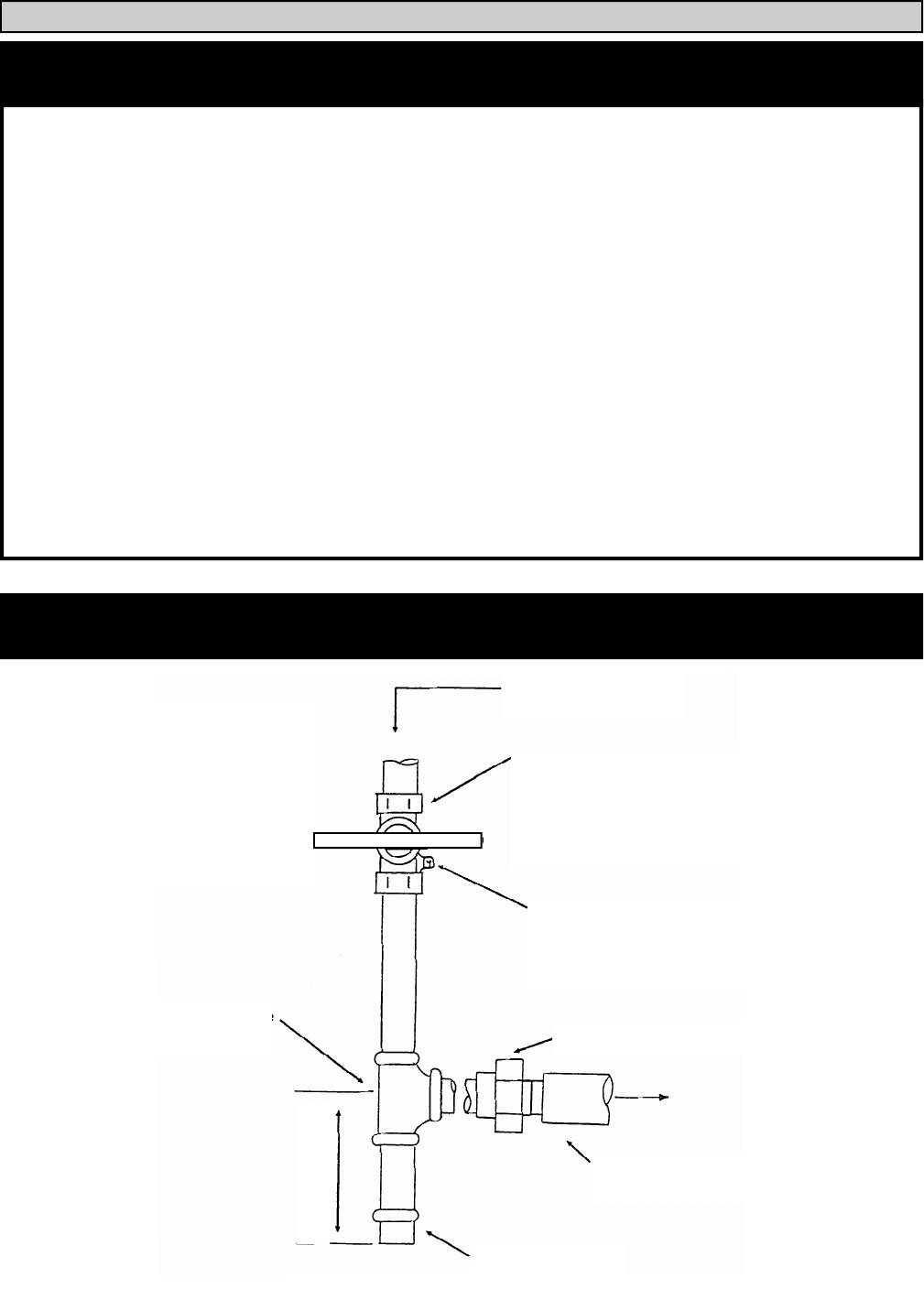
To check for
gas leaks, use
a gas detector
or apply a
soap solution
to the joints.
DO NOT USE AN
Direction of
flow
Manual Shutoff Valve
Height of shutoff valve
above ground level to
conform to local codes,
Pressure Gauge
Port
(1/8” NPT plugged)
Minimum
1” X 1” X 1” Tee Male Union 1” NPT
Burner Gas
Pipe Cap
3” MINIMUM
INSTALLATION OF SEDIMENT TRAP AND BURNER SUPPLY
Gas supply piping is to be sized and installed properly in order to provide a supply of gas sufficient
to meet the maximum demand without undue loss of pressure between the meter and the boiler. It is
advisable to run a separate gas line from the meter to the gas burner to avoid pressure drops. Consult
with the National Fuel Gas Code ANSI Z223.1 for proper sizing of gas piping for various lengths and
diameters.
Locate a drop pipe adjacent to, but not in front of the boiler. Locate a tee in the drop pipe at the
same elevation as the gas inlet connection to the boiler. Extend the drop line with a nipple towards the
floor and cap to form a sediment trap. Install a tee handle shut off valve before the tee with sediment
trap and a union after the tee before the combination gas valve.
When installing the boiler, Use black steel pipe and malleable fittings (do not use cast iron parts) with
a suitable pipe dope which is resistant to liquefied petroleum gases.
Check piping for leaks. Always check leaks with a water and soap solution. DO NOT USE A
FLAME FOR CHECKING GAS LEAKS
The boiler and its individual shut-off valve must be disconnected from the gas supply piping
during any pressure testing of that piping at test pressures in excess of 1/2 psi.
9. Gas Line Piping
PAGE 13
BIASI B/40
Piping should consist of:
1. A shut off valve approximately 6’ away from the unit.
2. A 1/8” plugged NPT tapping for gas pressure measurement preferably on the manual
shut-off valve (as shown or anywhere between the gas valve and the shut off value).
Note: The manual shut off valve and tapping are NOT part of the SU-4 Gas Burner.
Please make sure you conform to local and state codes.
3. A gas union.
4. A drip pipe.
Caution: The gas valve should not be subjected to more than ½” PSIG. Therefore, the
burner should be isolated during high-pressure gas leak tests. The appliance and its
individual shut off valve must be disconnected from the gas supply piping system
during any pressure testing of that system at test pressures in excess of ½ psig. The
appliance must be isolated from the gas supply piping by closing its individual man-
ual shut off valve during any pressure testing of the gas supply piping system at test
pressures equal to or less than ½ psig.
INSTALLATION OF SEDIMENT TRAP AND BURNER SUPPLY
BIASI B/40
PAGE 14
The B-40 Linear boiler is a high efficiency unit that requires proper venting. The boiler must
be vented to the outdoors by means of a tile lined masonry or an approved pre-fabricated chimney of
the size and height recommended by the manufacturer or by a listed "power venting" unit which
provides draft by mechanical venting .
The chimney discharge opening must be located at least 24 inches above any part of the
building structure within 10 feet of the chimney. Be sure the chimney and smoke pipe don't become
obstructed by squirrels, bird nests, soot buildup, chimney liner deterioration, etc. The "power ventor"
system should be installed on the leeward side of the building. Very specific requirements must be
met concerning clearances from combustibles and distances from doors and windows. Please consult
with manufacturer of "power ventor" for this information. In any case, the "ventor" must be installed
by a licensed burner mechanic and done in accordance with local codes. The B-40 boiler is a very low
stack temperature boiler (between 320 and 400F gross stack temp.) so caution should be used when
connecting to an outside built chimney. Should you have concern that the flue gases could condense,
then you should consider using a listed, "power venting" unit. If "power venting" is used to discharge
flue gases, then the power vent unit should be equipped with a postpurge control as well as delay-off,
timing control to prevent problems with fogging and nozzle post drip.
Note: 88% steady state efficiency is achieved when flue gas contains over 12.5% CO2 and the gross
stack temp. is below 350F.
The smoke-pipe connection from the boiler to the chimney should be as short as possible, with
a minimum number of elbows. The vent pipe must have a vertical rise of at least 1/4 inch per foot of
horizontal run. The vent pipe must be of the same diameter as the flue outlet on the boiler. The
chimney connector should have a minimum thickness of 24 gauge, corrosion resistant (galvanized)
steel, assembled with a minimum of three (3) sheet-metal screws, and sealed with high temperature
silicon at each joint. In most cases a barometric draft control isn't recommended as the B-40 is
designed to be pressure-fired. However, one may be needed if the boiler is being used in a high draft
situation.
10. Breeching and Venting:
PAGE 15
BIASI B/40
All piping must conform to state and local codes.
The supply and return manifolds for B-40 Linear boilers are 2 1/2” male NPT. Be sure to
provide unions and gate valves at the manifold inlet and outlet of the boiler, so the boiler may be
readily isolated for service.
Install the provided pressure relief valve so the discharge is piped directly to a drain, if
possible. If not, the discharge should be piped to the floor. In either case, the discharge pipe should be
of the same diameter as the outlet of the relief valve, with no valves or obstructions to impede
overflow from the boiler. The installation locations on the manifold for the Pressure Relief Valve, the
Temperature/Pressure Gauge as well the Honeywell L4006E Aquastat can be seen on the following
page.
Install manual and/or automatic air venting devices at the high points in the system to eliminate
trapped air.
The weight of all piping should be supported by suitable hangars and floor stands, not by the
boiler.
It is recommended that the make-up water line have a backflow preventer and a pressure-
reducing valve to reduce line pressure to 10 to 15 psi installed adjacent to the boiler.
NOTE: If the heating system is to be filled with antifreeze, use only formulations expressly made for
hydronic heating systems (such as propylene glycol). Do not use automotive types of antifreeze
(ethylene glycol). Use of antifreeze will alter system output and characteristics. Consult factory rep's
for details or assistance.
Clearance for hot water pipes are 1 inch to combustibles.
11. Piping:
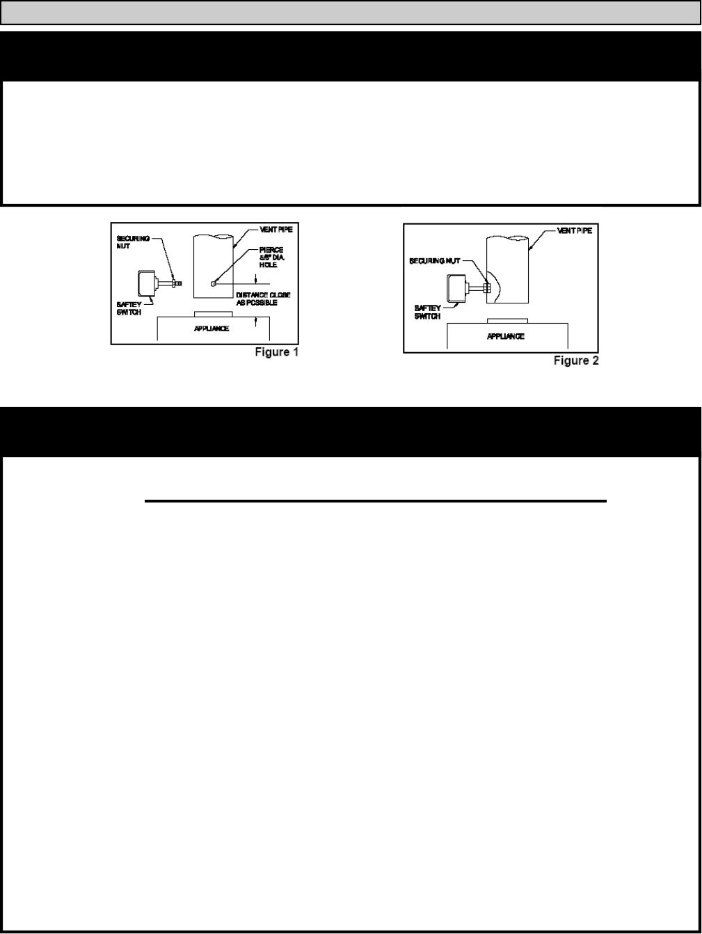
1. Pierce a 5/8” hole into the vent pipe near the appliance outlet. Remove one of the securing nuts
from the pipe of the safety switch. Tighten the other securing nut onto the pipe as far as possible.
2. Insert the threaded pipe end into the pierced hole, then install the securing nut, then install the se-
curing nut, which was removed in step 1, and tighten securely.
3. Please consult the wiring section of this manual for the wiring of the blocked flue switch.
10. Blocked Flue Switch:

BIASI B/40
PAGE 16
PAGE 17
BIASI B/40
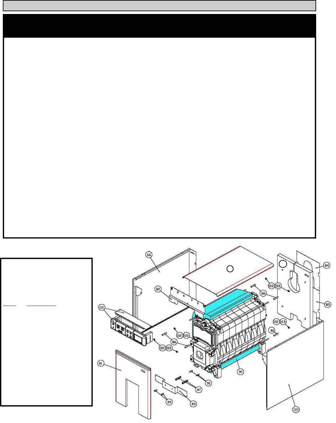
NOTE: All piping, boiler controls, gauges and valves must be installed before the jacket has been
assembled on the boiler. Refer to the following page to clarify these boiler jacket assembly
instructions.
Insert the separate piece of insulation (# 92) on top of boiler so the entire top and sides of boiler
are covered. Use plastic strapping to secure the insulation in place. Mount the panel installation
bracket (#82) onto the draw-rods on the upper front of the boiler. Install the six spacers (#86) onto the
draw-rods. Two on the upper draw rods in the front and the remaining spacers onto the draw-rods in
the back of the boiler. Install the rear insulation (#101) onto the boiler. Place the side panels (#66,52)
onto the boiler making sure the draw rod spacers are between the side panels and the boiler casting.
Tighten the sides of the casing to the panel installation bracket (#82) using sheet metal screws. Screw
two studs (#90) into the bottom front of the boiler and screw on the threaded hex spacers (#87) onto
the studs. Attach the lower mounting bracket (#83) to the boiler by using two bolts (#89) and screw-
ing them into the threaded hex spacers. Then using sheet metal screws, attach the lower mounting
bracket to the sides of the casing. Slide the control panel (#110) onto the casing from the top and se-
cure it to the control panel support (#82) using sheet metal screws. Attach the rear panels (#84,85)
using sheet metal screws. Place the top panel (#76) onto the sides of the casing and assure that the
pins on the sides are aligned with the retaining holes on the top casing panel. Finally attach the front
panel (#81) onto the casing by aligning the retaining pins with the retaining holes. Push to insure a
positive connection.
12. Boiler Jacket Assembly:
Boiler Components &
Parts Vega B40 - Series
Boiler Jacket Assembly:
Part# Description
84,85 — Rear Jacket Panels
*1
92,101— Insulation
52 — Right Jacket Panel
66 — Left Jacket Panel
83 — Front Jacket Supports
110 — Control Panel
82 — Control Panel Support
76 — Top Jacket Panel
81 — Front Jacket Panel
*2
*1
Rear insulation not attached, but
included with the casing
*2
Front insulation attached to the
casing
76
101
BIASI B/40
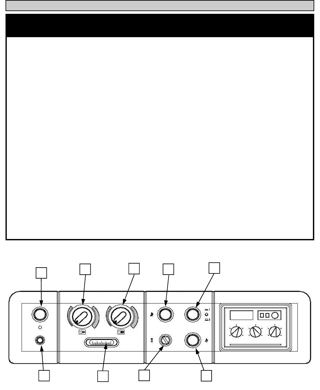
PAGE 18
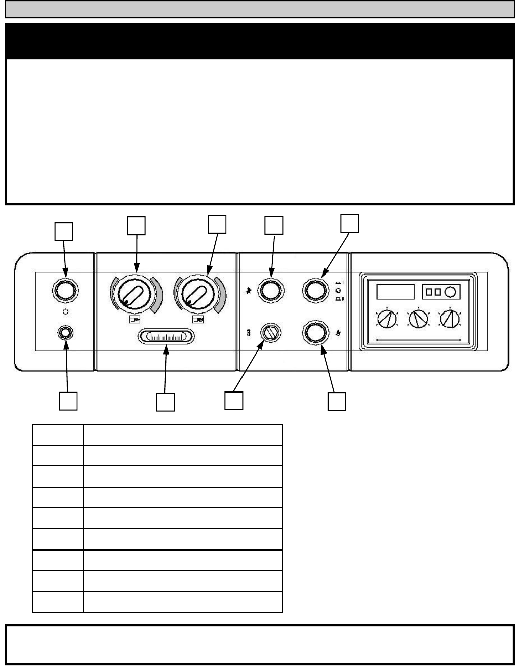
1 2 3 4 5
6 7 8 9
1 On/Off Switch
2 Min. Boiler Temp. Thermostat
3 Max Boiler Temp. Thermostat
4 Thermostat By-Pass Button
5 Circulator Switch
6 Boiler On/Off Signal Lamp
7 Temperature Gauge
8 Manual Reset High Limit
9 Burner Lock Out Signal Lamp
* NOTE: If the thermostat test button is closed, the thermostats will be bypassed and the burner
will not shutoff until the boiler reaches the manual high limit.
The electricity to the boiler shall come from a dedicated breaker in the electric service box. A
service switch should be mounted on the side of the boiler so the burner man can service the burner
and controls. The electrical wiring should be routed so as not to interfere with normal servicing of the
boiler. Wiring done in the field between devices not attached to boiler shall conform with the
temperature limitations for type T wire (63F/35C) or other specified wire as applicable when installed
in accordance to manufacturer's
instructions and wiring diagrams.
Please refer to the wiring section of this manual for instructions on wiring the supplied control
panel.
13. Wiring:
PAGE 19
BIASI B/40
1 2 3 4 5
6 7 8 9
1. On/Off Switch — Turns power to control panel on and off and will disable power to the burner
assuming the panel is wired correctly.
2. Minimum Boiler Temperature Thermostat — Maintains a minimum boiler temperature be-
tween 50 degrees F and 170 degrees F.
3. Maximum Boiler Temperature Thermostat — High limit temperature setting for boiler be-
tween 50 degrees F and 205 degrees F.
4. Thermostat Test Button — This button jumps out both thermostats allowing a technician to eas-
ily start the burner for testing if there is no call for heat. Warning, with both thermostats disabled
the only high limit left will be the manual high limit.
5. Circulator Switch - Supplies power to boiler circulator or relay panel. It is not suggested to use
this switch and it is not utilized in any of the suggested wiring diagrams in this manual.
6. Boiler On/Off Signal Lamp — Signal lamp to indicate whether main power switch is turned on
or off.
7. Temperature Gauge - Temperature gauge which takes temperature reading from top front of
boiler.
8. Manual Reset High Limit - Safety high limit that is set to 214 degrees F. If the manual high
limit is tripped, use a flat head screw driver to protective cap on reset button. Then depress reset
button making sure that it stays depressed once you have removed your finger. Once the switch is
reset replace the protective cover.
9. Burner Lock Out Signal Lamp - Lamp to indicate if the burner has gone out on lockout.
CONTROL PANEL DESCRIPTION
BIASI B/40
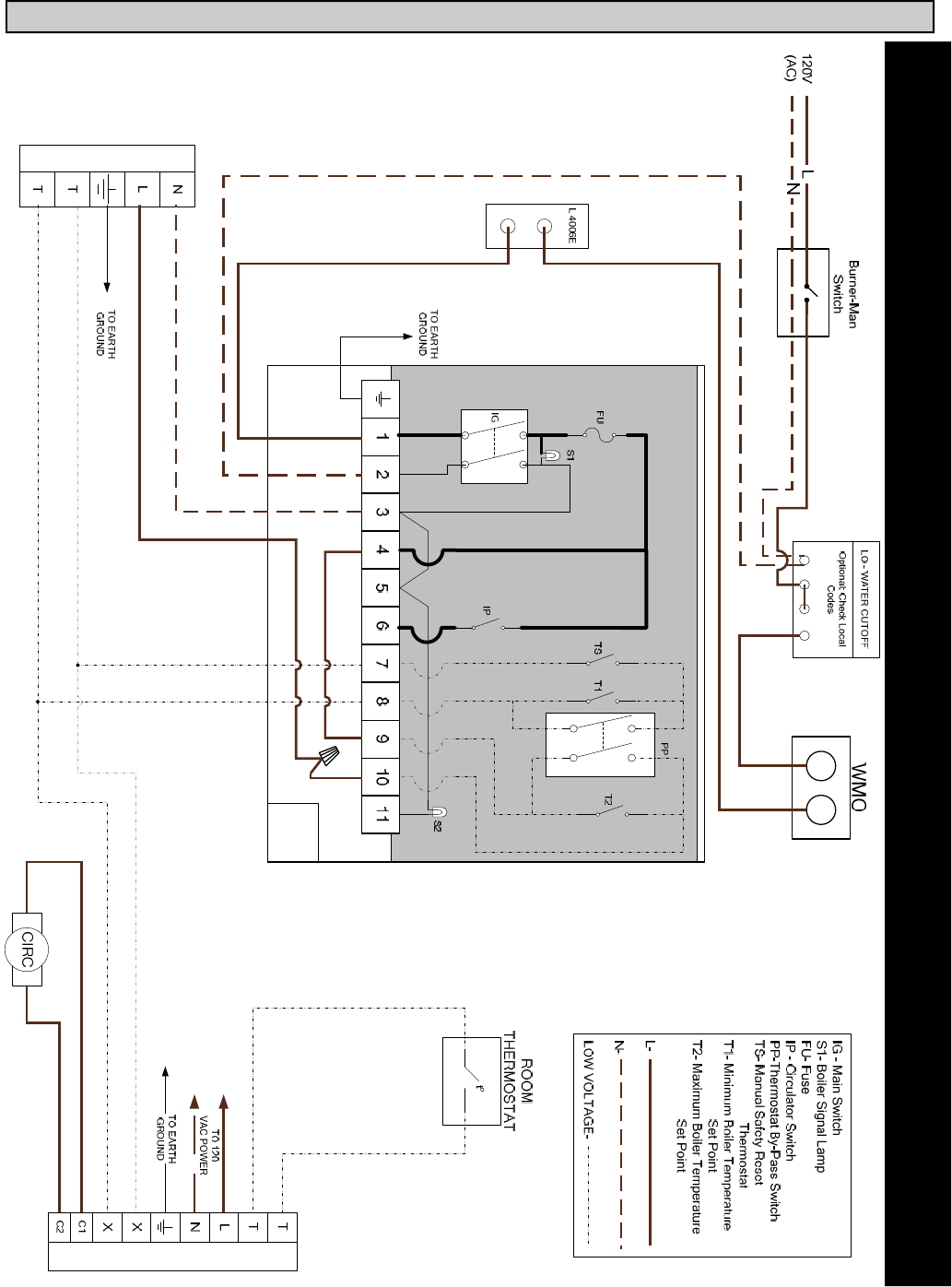
PAGE 20
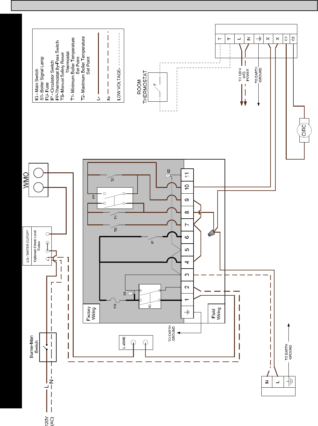
B-40 Control Panel Wiring Diagram for Beckett/Heat Wise Oil Burner 24V
CIRCULATOR RELAY
BURNER CONTROL
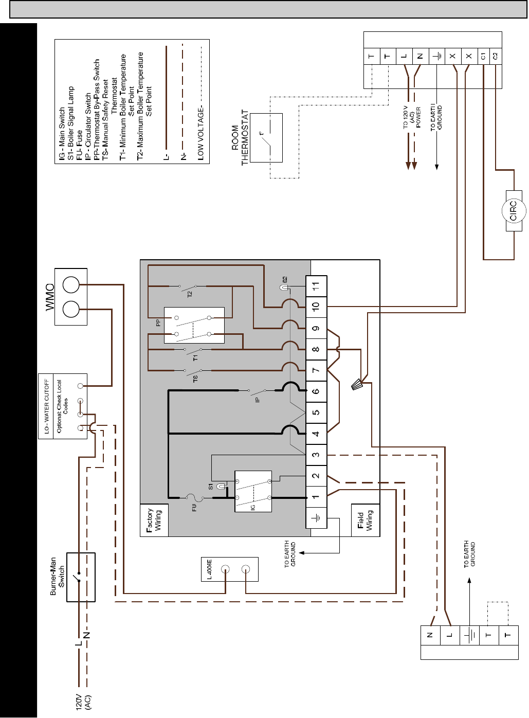
PAGE 21
BIASI B/40
B-40 Control Panel Wiring Diagram for Beckett/Heat Wise Oil Burner Line Voltage
CIRCULATOR RELAY
BURNER CONTROL
BIASI B/40
PAGE 22
B-40 Control Panel Wiring Diagram for Riello Oil Burner
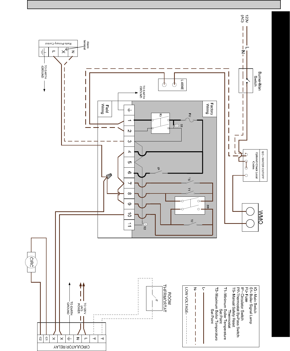
PAGE 23
BIASI B/40
B-40 Control Panel Wiring Diagram for Heat Wise Gas Burners
CIRCULATOR RELAY
Burner Primary Control
BIASI B/40
PAGE 24
Check for fouling or soot buildup in the combustion chamber at least every twelve (12)
months.
Caution: Black carbon soot in the combustion chamber can, under certain conditions, be
ignited by a spark or open flame. To prevent this unlikely occurrence, dampen the soot deposits with a
wet brush or a fine water spray before servicing or cleaning the combustion chamber. Fouling or
carbon soot buildup on the surfaces in the combustion chamber is caused by incomplete combustion,
and is a sign of combustion air and/or venting problems. As soon as any fouling is observed, the cause
of the fouling should be corrected and the combustion chamber should be cleaned as follows:
Disconnect the electrical power supply to the boiler, burner and controls. Close Fire-O-Matic thermal
shutoff valve at burner prior to servicing. Remove the front jacket panel (#9) and the loosen the two
(2) front boiler door nuts. Swing the boiler door open. Be careful not to damage the door stud threads
or the flexible oil line. Brush and vacuum combustion chamber and flue passages until all deposits are
removed. Reassemble components in reverse order, making sure any damaged gaskets are repaired or
replaced.
Other maintenance requirements are as follows: Inspect wiring and controls for damage. Insure
controls are operating correctly. Inspect oil or gas supply lines for damage, corrosion or leaks. Repair
any leaks immediately. Inspect, clean or replace oil filter as specified by manufacturer. Inspect vent
and fill pipes for any obstruction, damage or corrosion. Clean or replace as necessary. Lubricate the
burner motor if necessary during service. Finally, consult burner manual for specific burner
maintenance instructions.
14. Commissioning:
After installation of oil/gas-fired boiler, operation and performance tests shall be conducted to
make certain that the burner is operating in an acceptable manner and that all safety controls and
devices function properly. It is critical that the high limit, low water
cutoff and burner "cad cell" relay be checked for normal operation before leaving the job. Refer to the
back page of this manual to write down the System Checkout information.
15. Maintenance:

PAGE 25
BIASI B/40
System Checkout:
Boiler Model No._________________ Serial No.__________
Original Purchaser: Installer:
_________________________ ______________________
_________________________ ______________________
_________________________ ______________________
Burner Manufacturer----------- Type of Oil Burner-------------
Burner Model No.-------------- Burner Serial No.--------------
Nozzle Manufacturer------------- Nozzle Spray Angle------------
G.P.H. -------------------- Type -----------------------
Burner Performance Tests:
GROSS STACK TEMPERATURE --------------------
ROOM TEMPERATURE (AMBIENT) -------------------
NET STACK TEMPERATURE ---------------------
CO2 -----------------
O2----------------
SMOKE READING ----------------
COMBUSTION EFFICIENCY----------------------
COMMENTS
16. Installer Notes

BIASI B/40
PAGE 26

PAGE 27
BIASI B/40

BIASI B/40
PAGE 28
ITEM #: B40
REV. H
Warranty
For BIASI B40 Series Commercial
Cast-Iron Water Boilers
FIRST YEAR through TENTH YEAR-WARRANTY FOR B40 SERIES COMMERCIAL HOT WATER BOILERS: QHT warrants that
its cast-iron boiler and casing are free from defects in material and workmanship for ten years from the date of installation at the
original installation site to the original owner. If the boiler is found to be defective within this period, QHT will replace the
boiler block or casing.
ELEVENTH YEAR and BEYOND -WARRANTY FOR THE CAST IRON BOILER SECTIONS OF THE B40 SERIES COMMER-
CIAL BOILERS: Biasi warrants that the cast-iron sections of the BIASI B40 boilers are free from defects in material and
workmanship for the life of the original installation to the original owner. If the B40 boiler section is then found to be defective,
QHT and Biasi will replace the defective section of the cast iron boiler block.
This warranty is subject to the condition that a heating contractor whose principal occupation is the sale and installation of
heating equipment must have installed the boiler. In addition, the boiler must be installed in accordance with the boiler manual supplied by
QHT Inc with every boiler. PARTS, WHICH ARE COVERED, consists of all materials supplied by Biasi. Other parts supplied in the trim
kit or in the burner pack carry their own warranty and each manufacturer has responsibility for its own products.
NOTE: ANY PART, WHICH IS REPLACED UNDER WARRANTY, CARRIES ONLY THE UNEXPIRED PORTION OF THE
ORIGINAL WARRANTY.
OWNER RESPONSIBILITIES:
1. Provide for proper installation, which includes pressure relief and pressure reducing valves and high limit safety controls on closed
systems.
2. Provide qualified periodic service to prolong proper operation and service.
3. Insure that boiler is installed with approved burner and that installation conforms to all codes and ordinances.
4. This warranty does not apply to boilers, which are subject to misuse, abuse, neglect, alteration, accident, excessive temperature,
excessive pressure, or corrosive water or atmosphere.
5. Owner will be responsible for return of faulty components to Portsmouth, NH, freight pre-paid.
QHT AND BIASI WILL NOT BE RESPONSIBLE FOR:
1. Components that are part of the heating system, but were not manufactured by Biasi or QHT as part of the commercial boiler system.
2. The workmanship of the installers of Biasi B40 Linear boilers. Furthermore, this warranty does not assume any liability for
unsatisfactory performance caused by improper installation.
3. Any costs for labor to remove or replace the faulty component.
4. Improper burner application or adjustments, control settings, care or maintenance.
5. Any damage associated with corrosion or leakage due to the use of "non-barrier", plastic pipe in the heating system.
*THIS WARRANTY DOES NOT EXTEND TO ANYONE EXCEPT THE FIRST PURCHASER AT RETAIL AND ONLY WHEN THE
BOILER IS IN THE ORIGINAL INSTALLATION SITE.
*IMPLIED WARRANTIES OF FITNESS FOR A PARTICULAR PURPOSE AND MERCHANTABILITY SHALL BE LIMITED TO
THE DURATION OF THE EXPRESSED WARRANTY. BIASI AND QHT EXPRESSLY DISCLAIM AND EXCLUDE ANY
LIABILITY FOR CONSEQUENTIAL OR INCIDENTAL DAMAGES FOR BREACH OF ANY EXPRESSED OR IMPLIED
WARRANTY.
THIS WARRANTY GIVES YOU SPECIFIC LEGAL RIGHTS, AND YOU MAY HAVE
OTHER RIGHTS THAT VARY FROM STATE TO STATE.
For prompt warranty service, notify the installer, who, in turn, will notify the distributor from whom he purchased the boiler. If this does
not result in corrective action, contact Biasi through Quincy Hydronic Technology (Address Below) with details in support of the warranty
claim. All claims must be processed through proper trade channels. Contact with Biasi directly is not recommended for rapid claim
settlement.
Quincy Hydronic Technology,
3560 Lafayette Rd
Portsmouth, NH, 03801
Tel. (603) 334-6400
