Lionel RTPGRXV3 Thomas & Friends Ready to Play Set User Manual
Lionel L.L.C. Thomas & Friends Ready to Play Set
Lionel >
Contents
- 1. User Manual
- 2. User Manual 1
- 3. User Manual 2
User Manual

Mobile Bluetooth Sensor
User Manual
This manual does not contain the full content of the
function of the mobile Bluetooth sensor, please prevail in
kind. Future changes to the contents of the manual will
no longer be individually informed of the user. Please
read the entire manual carefully and follow the
instructions.
Product model: ITL-DK6500A
Last revision date: 29 September 2016
Chapter I Summary
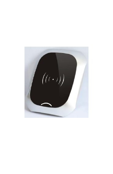
1.1 Product Introduction
Mobile Bluetooth Sensor using Bluetooth 4.0 Technology
to realize the access control for door and elevator through
data communication with Mobile APP.
Pic 1.1 Product diagram
1.2 Specifications
Power supply: DC 24V.
Working Currents: <100mA.
Usage Environment:
Temperature:-10~60℃.
Relative Humidity: 20%~90% non-condensing.
Storage Environment:

Temperature: -20~70℃.
Relative Humidity: 20%~90% non-condensing.
System Version: Android4.3 +, IOS7.0+
Communication Distance: 0~10M, there are some
errors in different environment
Responsive Speed: 0~3S for IOS,Android is related
to mobile phone.
RS485 external communication interface,
Transformat : 9600bps,8,N,1.
External Dimension: L120*W100*H21.34mm.
ChapterⅡ Hardware Instruction
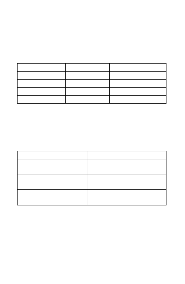
2.1 P1—connect with Access Controller
Interface
This interface is connected via shielded cables to the 24V
power terminals and to the access control elevator or door,
as described below:
Chart 2.1 Connected with access controller interface
P1
Interface Instruction
GND
Negative Power output
24V
Positive Power Input
485G
485 Ground Port
485A
485 A port
485B
485 B Port
2.2 SW1— Device DIP Setting
The DIP SW1.1 and SW1.2 are used to set the Mobile
Bluetooth Sensor number, if the access controller
connected with two or more sensors,The setting of SW1
of each device are different,specific setting described as
below:
Chart 2.2 Device DIP setting
SW1.2
SW1.1
Implication
OFF
OFF
1st Sensor
OFF
ON
2nd Sensor
ON
OFF
3rd Sensor
ON
ON
4th Sensor
SW1.3 and SW1.4 are reserved to extension
function,factory default is OFF.
2.3 LED1/LED2—Indicator Light instruction
Chart 2.4 LED instruction
LED1/LED2
Implication
The light is always on
Unauthorized device or
device fault
Light Flash Rapidly
(100ms/ times)
Failed communication
with the controller
Light Flash Slowly
(1S/time)
The device Bluetooth is
working properly
ChapterⅢ User APP Instruction
Mobile Bluetooth Sensor using Bluetooth 4.0 technology,
it requires the mobile version should be Android 4.3 above
or IOS 7.0 above.
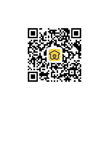
Users need to download our APP for application, you can
directly scan the following QR code or search “Jia-R”in
the Application Store for download and installation.
Pic 3.1 Jia- R App QR Code
Chapter IV Instruction
After connecting the main controller with the mobile
Bluetooth Sensor , power on the main controller, initialize
the device, and download the corresponding parameters
Device Authorization
The mobile Bluetooth sensor have to be authorized again
after its first use and initialization. The authorized
operation setting by APP and completed under the
guidance of our engineering staff.

Installation and Register of App
After the installation of user APP, open the APP and
register through user’s mobile number and verification
message, we suggest that user using current mobile
number for registering
Authorization via Administrator
For registered users, you must be authorized by the
administrator in the background through the cloud user
rights information which will be synchronized to the
phone terminal, you can see the device permissions. If you
can not see the authorized device icon after authorization,
you can quit the App to log in again.
Access modes
The APP supports three access modes : Manual click,
Auto-sensing and shake mode , Login the APP and enter
the setting menu and do the modification of access mode
as you like.
Manual Click:When user enters area around the
mobile Bluetooth Sensor, the mobile app can detect the
device, and the icon of the corresponding device is
lighten, just manually click the icon, then the App will
connect with the device and send the control signal to
the sensor device to approve the access
Auto-sensing:After user turns on the auto-sensing
mode, he or she enters area around mobile Bluetooth
Sensor, the APP can detect the device and
automatically connect and send the control signal to
the device for access approval. NOTE: it
will automatically turn on the device once from
Non-sensing area into the sensing area, if you need to

open repeatedly, you can use manual click or shake
mode.
Shake Mode:Shake mode and manual click mode
are similar, but the trigger from click to shake mode.
Chapter V Device Installation and
Debug
5.1 Precautions
Mobile Bluetooth sensor can be used for access control
or elevator equipment,it can be mix used with the
standard split access reader or elevator reader,
controlling the same door or same elevator and does
not affect the original functions of elevator.
As to the RS-485 communication, in order to ensure
the communication quality, it requires double-shielded
twisted-pair RVVP * 0.75m㎡ cable, the connection
distance with controller should be limited within 50
meters
Due to the Bluetooth interfered by the metal
environment, please try to install the device away from
the metal environment.
5.2 Device Installation Position
The Mobile Bluetooth Sensor can be installed in the
exposed position or hidden installation. It depends on the
construction site and customer requirements.
Normally the device installed around gate for
access control.

Device installed around the elevator Hall for
calling elevator system.
Device installed hidden on the top of lift for floor
access control.
5.3 Wiring and Debug
P1 is connected with the controller interface, the P1 is
connected to the controller 485 reader interface. NOTE:
485A and 485B do not reverse.
Re-power the equipment after connection, other
connections and debugging can refer to the previous
indication
Chapter VI Trouble-shootings
Here are some possible phenomena and simple ways to
check them. Please cut off power before any operation on
the hardware.
Symptom 1: App is unable to detect device normally
Possibility:
Please confirm if the device is authorized or not,
if not, please do the authorization for device by APP.
If the indicator LED flash rapidly, it maybe the
abnormal state of controller communication, please check
the wiring, if it is working abnormally, try to connect the
terminal resistance.
The mobile version too low with poor Bluetooth
compatibility, please try to change another mobile phone
for testing.
Bluetooth signal is interfered or blocked by

environment,please try to change the installation site or
search device closely.
Symptom2: Manual click unsuccessfully or open
failed
Possibility:
No authorization,please confirm you click device is
authorized.
Out of the sensing range (Display icon is in black
color), gradually close to the device (till the display
icon turn into white color)
Mobile system version too low with poor Bluetooth
compatibility, try to change another mobile phone.
Restart mobile phone
Chapter VII Regulatory
Note:This equipment has been tested and found to
comply with the limits for a Class B digital device,
pursuant to part 15 of the FCC Rules. These limits
aredesigned to provide reasonable protection against
harmful interference in a residential installation. This
equipment generates uses and can radiate radio frequency
energy and, if not installed and used in accordance with
the instructions, may cause harmful interference to radio
communications. However, there is no guarantee that
interference will not occur in a particular installation. If
this equipment does cause harmful interference to radio or
television reception, which can be determined by turning
the equipment off and on, the user is encouraged to try to

correct the interference by one or more of the following
measures:
Reorient or relocate the receiving antenna.
Increase the separation between the equipment and
receiver.
Connect the equipment into an outlet on a circuit
different from that to which the receiver is connected.
Consult the dealer or an experienced radio/TV
technician for help
Caution:Changes or modifications not expressly
approved by the party responsible for compliance could
void the user's authority to operate the equipment.
Warning:This device complies with Part 15 of the FCC
Rules. Operation is subject to the following two
conditions: (1) this device may not cause harmful
interference, and(2) this device must accept any
interference received, including interference that may
cause undesired operation.