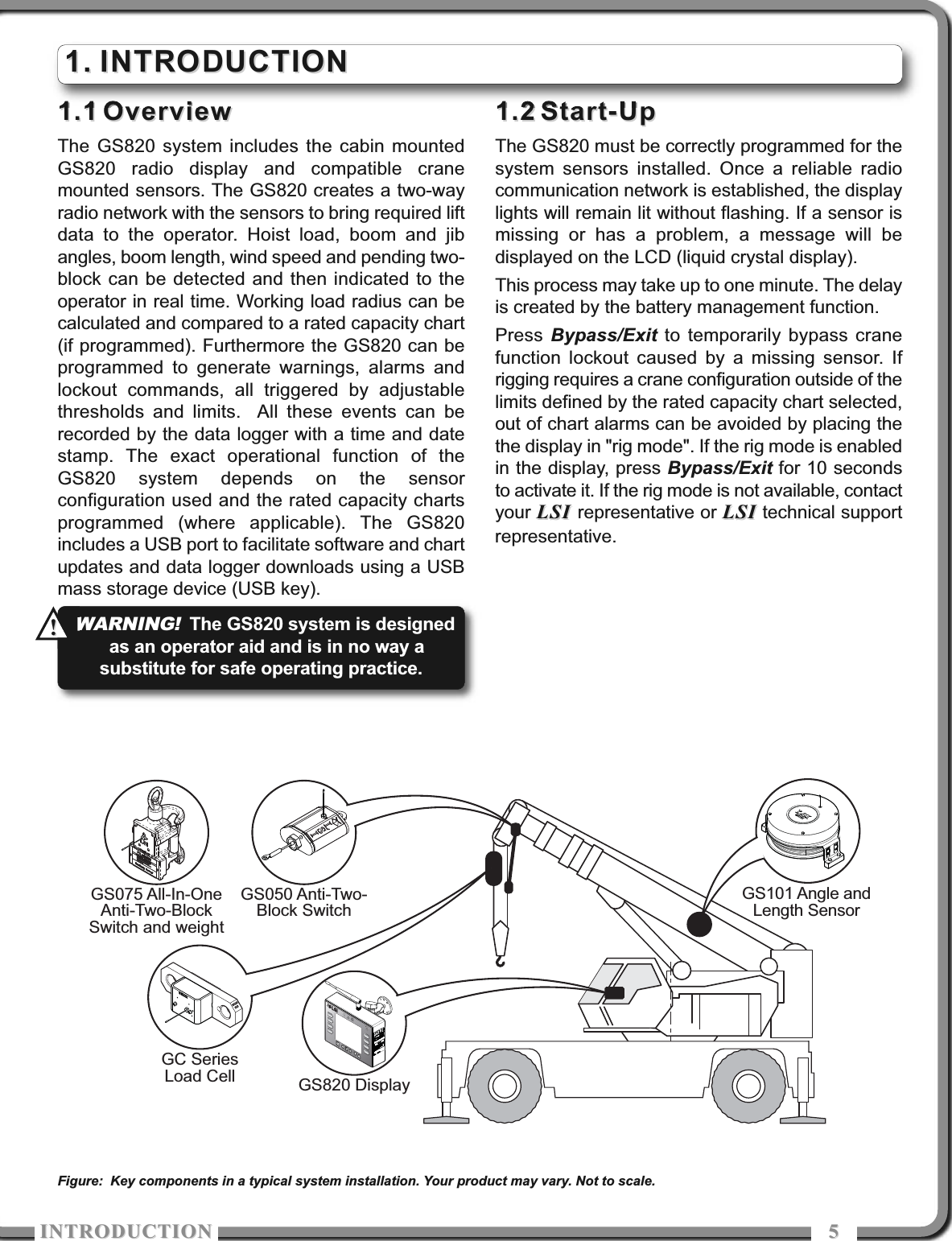
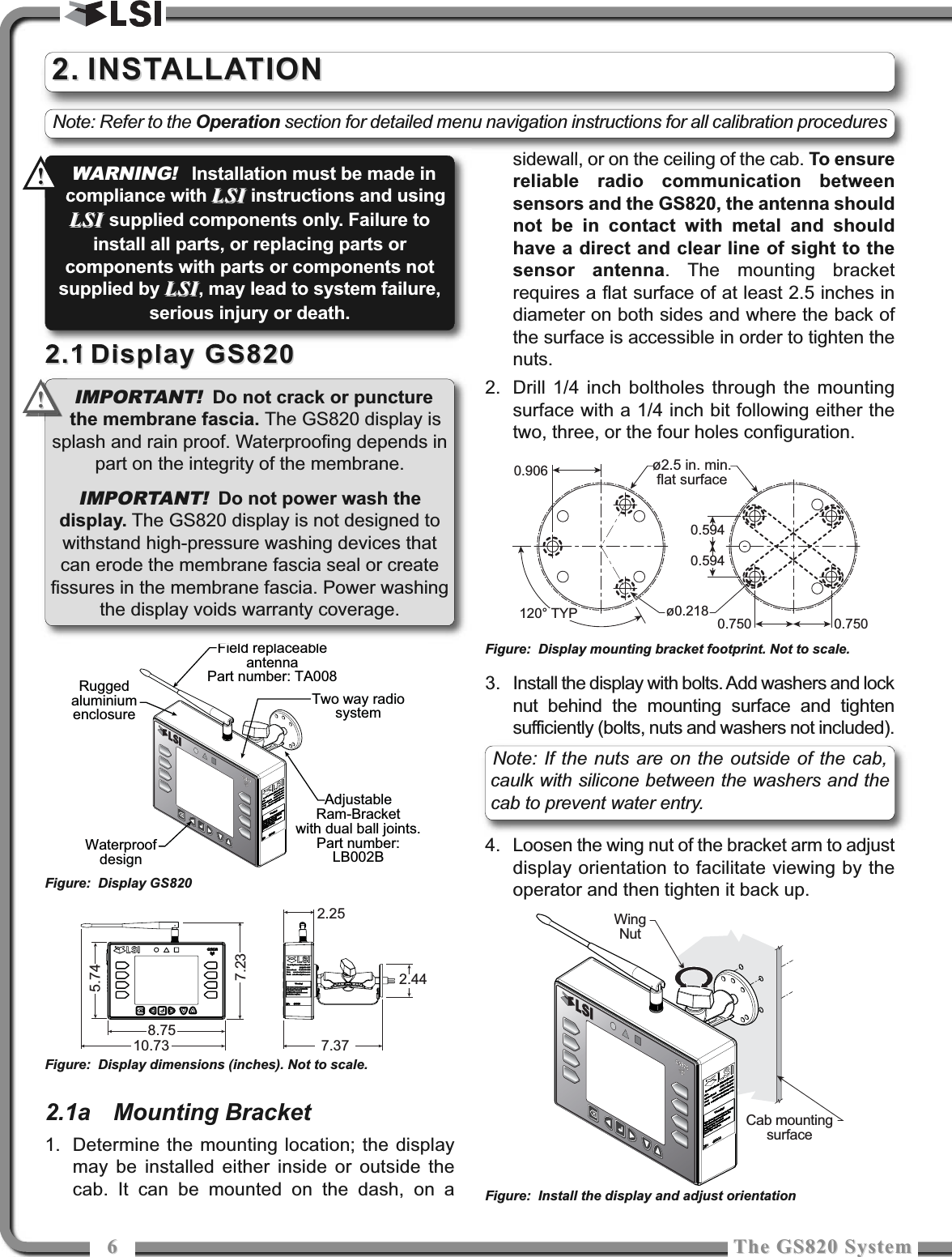
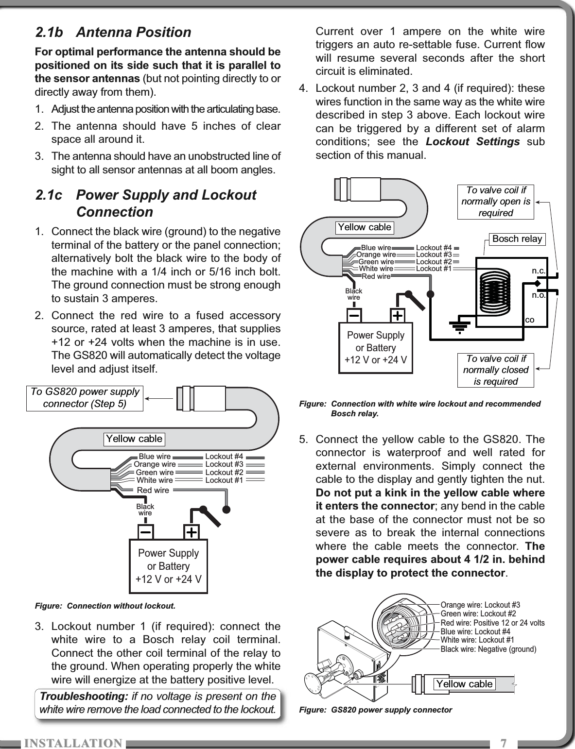
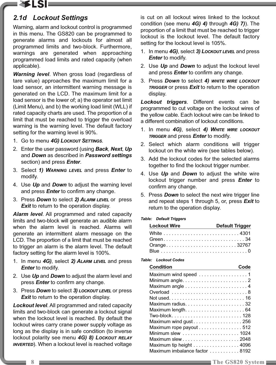
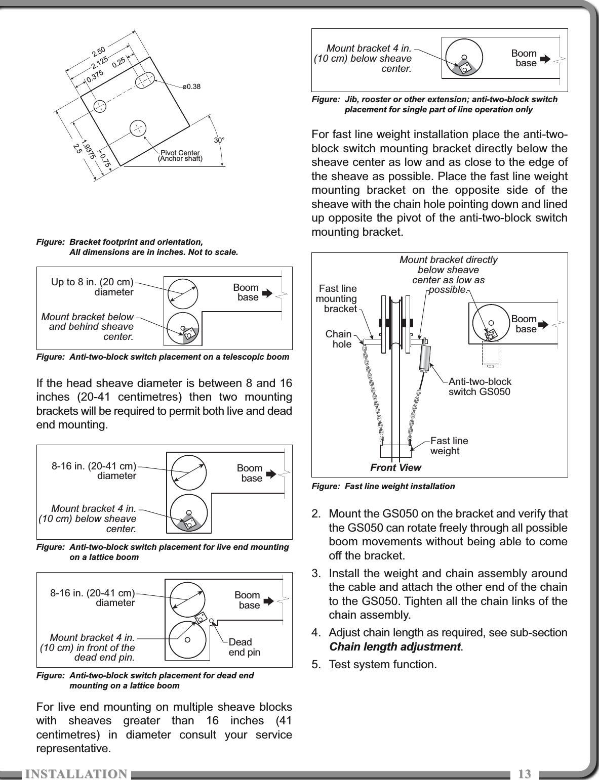
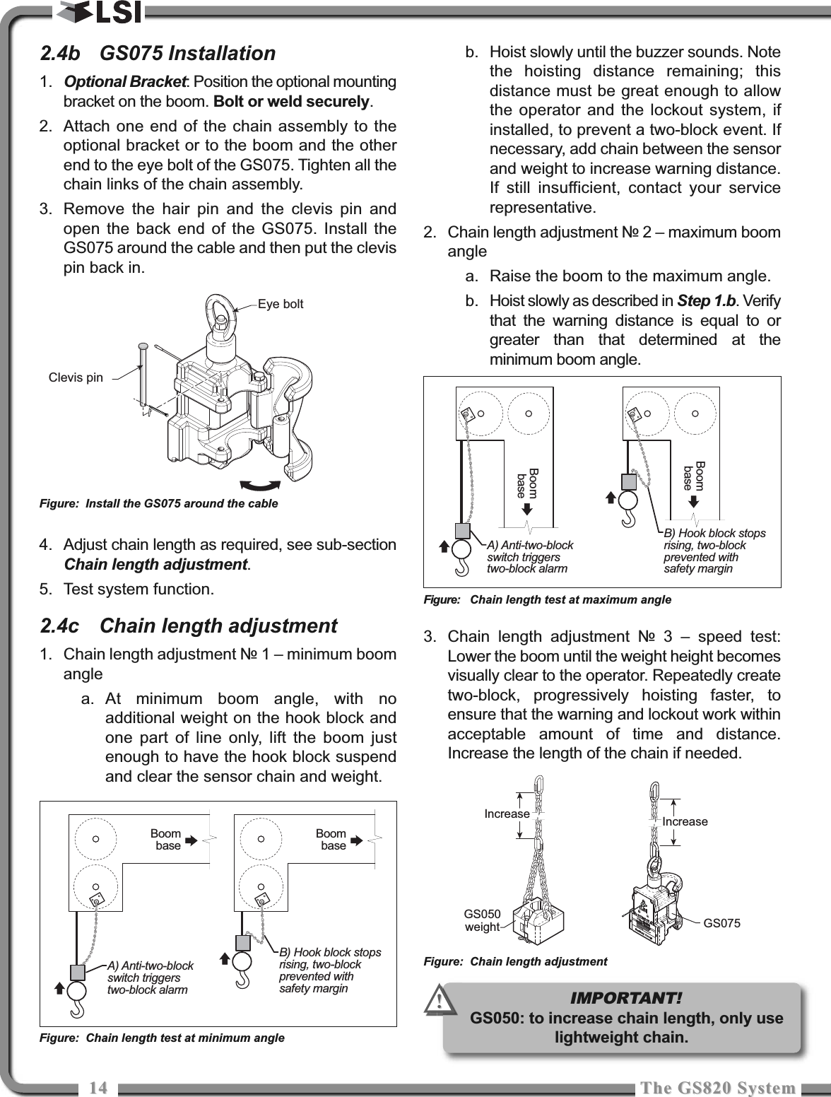
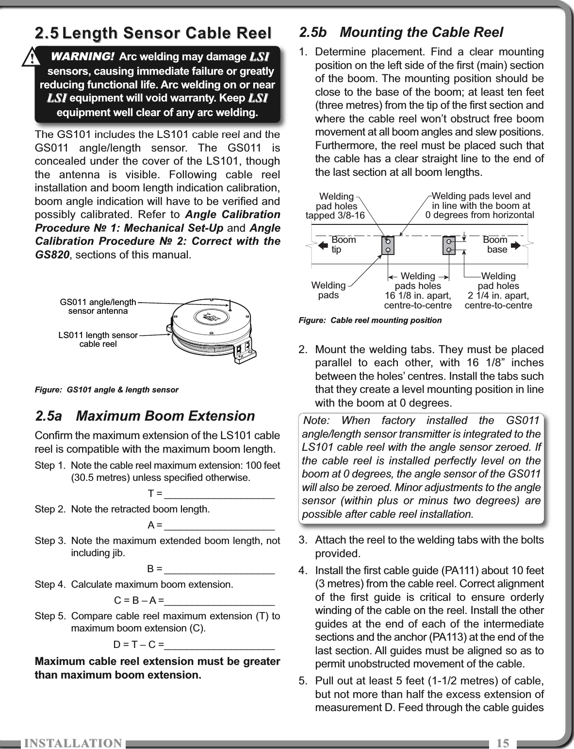
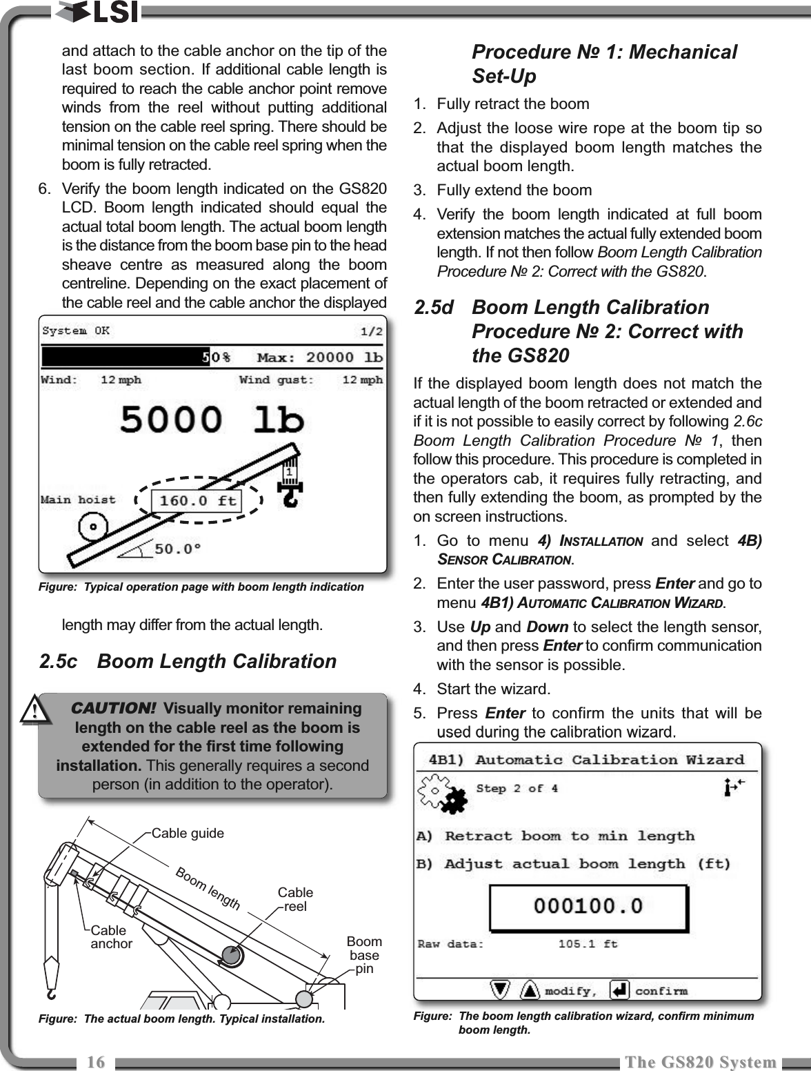
Load Systems GS001 GS012: Angle Length Sensor; GS035: Pressure Transducer User Manual

Load Systems International, Inc. GS012: Angle Length Sensor; GS035: Pressure Transducer

User Manual

GS820 Display& GS Series SensorsINSTALLER AND USER’S MANUALINSTALLER AND USER’S MANUALGM820   REV.20100402 www.loadsystems.comManufacturers of WirelessWeighing SystemsWARNING!The GS820 system is designed as an operator aid and is in no way asubstitute for safe operating practice.!!WARNING!Carefully read and understand this manual before proceeding.!!
22The GS820 SystemThe GS820 SystemRead and understand the following:For your safety and that of the people that comeinto contact with LSILSI products, understand thesignificance of the instructions included in thisguide, respect all laws and regulations and complywith applicable standards.Pay particular attention to items bearing the alertsymbol  and the following words:Warning: this denotes an instruction that if notcomplied with may lead to serious injury or death.Caution: this denotes an instruction that if notcomplied with may lead to product failure orproperty damage.Important: this denotes an instruction that if notcomplied with may lead to product performanceissues.!!IMPORTANT! WARNING!!!!!CAUTION!!!BEFORE PROCEEDINGBEFORE PROCEEDINGWARNING!Installation must be made incompliance with LSILSI instructions and usingLSI LSI supplied components only. Failure toinstall all parts, or replacing parts orcomponents with parts or components notsupplied by LSILSI, may lead to system failure,serious injury or death.!!
TABLE OF COTETSTABLE OF COTETS 331. INTRODUCTION1.1 OVERVIEW ........................................51.2 START-UP..........................................52. INSTALLATION2.1 DISPLAY GS820................................62.1a Mounting Bracket ........................................62.1b Antenna Position ........................................72.1c Power Supply and Lockout Connection ......72.1d Lockout Settings ........................................82.1e Password Settings ......................................92.2 LOAD CELL ....................................102.3 ANGLE SENSORS ..........................112.3a Mounting Procedure..................................112.3b Angle Calibration Procedure № 1:Mechanical Set-Up....................................112.3c Angle Calibration Procedure № 2: Correct with the GS820 ............................122.4 ANTI-TWO-BLOCK SWITCH ..........122.4a GS050 Installation ....................................122.4b GS075 Installation ....................................142.4c Chain length adjustment ..........................142.5 LENGTH SENSOR CABLE REEL ....152.5a Maximum Boom Extension ......................152.5b Mounting the Cable Reel ..........................152.5c Boom Length Calibration Procedure № 1:Mechanical Set-Up....................................162.5d Boom Length Calibration Procedure № 2:Correct with the GS820 ............................162.6 RADIUS ..........................................172.6a Radius Verification and Adjustment ..........172.6b Radius Settings ........................................182.6c Basic Radius Parameters for a LatticeCrane ......................................................192.6d Basic Radius Parameters for a TelescopicBoom Crane..............................................192.6e Advanced Radius Parameters ..................202.6f Radius Parameters for a Lattice Crane withMast ..........................................................212.7 WIRELESS WIND SPEED SENSORGS020 ..............................................222.8 WIRELESS LOAD PINS..................232.8a LP011, LP015, and LP026 ........................232.8b Load Pin Transmitter GS001 ....................232.9 LINE RIDING TENSIOMETER ........242.9a Line Riding Tensiometer Installation ........242.9b Line riding tensiometer installation on aswing arm..................................................252.10 LOAD PINS, LINE RIDINGTENSIOMETERS ANDCOMPRESSION CELLS:CALIBRATION ................................262.11 FOUR POINT LIFT ..........................272.11a Sum Load Indication ................................272.11b Imbalance ................................................272.11c Slack Rope................................................282.12 LIST AND TRIM ANGLE SENSOR 292.12a Programming the GS820 for List and TrimIndication ..................................................292.12b Mounting Instructions................................292.12c List and Trim Angle Calibration Procedure ..302.13 ROPE PAYOUT................................312.13a Rope Payout Calibration Procedure № 1:Mechanical Set-Up....................................312.13b Rope Payout Calibration Procedure № 2:Correct with the GS820 ............................312.13c Rope Payout Limits ..................................322.13d Electrical connections ..............................322.14 DATA LOGGER ..............................332.14a Recording Modes......................................332.14b Date and Time ..........................................332.15 SENSOR LIST ................................342.15a How to Add a Sensor to the GS820 ..........342.15b How to Remove a Sensor from the GS820 ..342.16 NETWORK OPTIONS ....................342.16a Listen to sensor only ................................342.16b Remote monitoring....................................352.16c Repeater ..................................................352.16d Wireless Sensor Update ..........................363. OPERATION3.1 DISPLAY GS820..............................373.2 USB PORT ......................................373.3 KEYPAD ..........................................373.4 DISPLAY LIGHTS............................373.5 MENU SYSTEM ..............................383.5a Menu Numbers ........................................38TABLE OF CONTENTSTABLE OF CONTENTS
44The GS820 SystemThe GS820 System3.5b Menu Navigation ......................................383.5c Password Protection ................................383.5d Menu Layout ............................................383.5e Parts of Line..............................................393.6 RATED CAPACITY INDICATORS ..393.6a Display Programming................................393.6b Crane Rigging ..........................................393.6c Chart Wizard  ............................................393.7 DISPLAY SETTINGS ......................403.7a Units..........................................................403.7b Backlight Mode ........................................403.7c Wind speed units ......................................403.8 SYSTEM DIAGNOSTIC ..................403.8a System Sensors Diagnostic ......................403.8b Radio Network Diagnostic ........................413.8c Lockout Diagnostic....................................413.8d Display Diagnostic ....................................413.8e Digital Input Diagnostic ............................413.9 SYSTEM LIMITS..............................423.10 TARE................................................423.11 INFORMATION ................................423.12 MAST SETTINGS ............................444. USB TOOL4.1 DATA LOGGER TRANSFER FROMDISPLAY ..........................................454.1a Transfer from display to USB ....................454.1b Transfer from USB device to PC ..............454.1c Troubleshooting ........................................454.2 UPLOAD CAPACITY CHARTS ......464.3 DATA LOGGER VIEWER  ..............464.3a Installation on a PC ..................................464.3b Quick Start ................................................464.3c Full Report ................................................464.3d Wind Report ..............................................475. MAINTENANCE5.1 SENSORS........................................485.1a Replacing Sensor Battery ........................485.2 ANTI-TWO-BLOCK SWITCH ..........495.2a Replacing the GS050 Batteries ................495.2b Replacing the GS075 Battery ..................495.3 REPLACING A SENSOR ANTENNA..505.4 LOAD CELLS ..................................515.4a Reading Accuracy ....................................515.4b Load Testing..............................................515.4c Care ..........................................................516. TROUBLESHOOTING ..................527. CERTIFICATION NOTES7.1 MODEL NUMBERS ........................537.2 IMPORTANT NOTES FORHAZARDOUS AREA CERTIFIEDCOMPONENTS ..............................537.2a Specifications............................................537.2b Ensuring Safe Operation in HazardousAreas ........................................................537.2c Product Repair And Servicing ..................537.3 EQUIPMENT MARKINGS ..............537.4 CLASS 1 DIVISION 1 AND DIVISION2 CERTIFICATIONS ........................547.5 ATEX CERTIFICATIONS ................547.6 FCC AND IC – INSTRUCTIONS TOTHE USER ......................................557.7 EMI / EMC........................................567.8 ENVIRONMENTAL CONDITIONS ..567.9 CE ....................................................577.9a Declaration of conformity ..........................577.9b CE Safety..................................................578. GS820 MENU OUTLINE ..............589. LSI PRODUCT LIMITEDWARRANTY - 2009/02/169.1 LIMITED WARRANTY ....................609.2 WARRANTY SERVICESPROCEDURES................................609.3 EXCLUSION OF OTHERWARRANTIES ................................609.4 EXCLUSION ....................................619.5 LIMITATION OF LIABILITY ............619.6 RECOMMENDED PRACTICES ......619.7  CHOICE OF LAW ............................619.7a Entire Agreement ......................................61
ITRODUCTIOITRODUCTIO 551.11.1 OverviewOverviewThe GS820 system includes the cabin mountedGS820 radio display and compatible cranemounted sensors. The GS820 creates a two-wayradio network with the sensors to bring required liftdata to the operator. Hoist load, boom and jibangles, boom length, wind speed and pending two-block can be detected and then indicated to theoperator in real time. Working load radius can becalculated and compared to a rated capacity chart(if programmed). Furthermore the GS820 can beprogrammed to generate warnings, alarms andlockout commands, all triggered by adjustablethresholds and limits.  All these events can berecorded by the data logger with a time and datestamp. The exact operational function of theGS820 system depends on the sensorconfiguration used and the rated capacity chartsprogrammed (where applicable). The GS820includes a USB port to facilitate software and chartupdates and data logger downloads using a USBmass storage device (USB key).1.21.2 Start-UpStart-UpThe GS820 must be correctly programmed for thesystem sensors installed. Once a reliable radiocommunication network is established, the displaylights will remain lit without flashing. If a sensor ismissing or has a problem, a message will bedisplayed on the LCD (liquid crystal display).This process may take up to one minute. The delayis created by the battery management function.Press Bypass/Exit to temporarily bypass cranefunction lockout caused by a missing sensor. Ifrigging requires a crane configuration outside of thelimits defined by the rated capacity chart selected,out of chart alarms can be avoided by placing thethe display in "rig mode". If the rig mode is enabledin the display, press Bypass/Exit for 10 secondsto activate it. If the rig mode is not available, contactyour LSI LSI representative or LSILSI technical supportrepresentative.1.1. INTRODUCTIONINTRODUCTIONGS050 Anti-Two-Block SwitchGS075 All-In-OneAnti-Two-BlockSwitch and weightGS101 Angle andLength SensorGS820 DisplayGC SeriesLoad CellFigure: Key components in a typical system installation. Your product may vary. Not to scale.WARNING!The GS820 system is designedas an operator aid and is in no way asubstitute for safe operating practice. !!
66The GS820 SystemThe GS820 System2.12.1 Display GS820Display GS8202.1a Mounting Bracket1. Determine the mounting location; the displaymay be installed either inside or outside thecab. It can be mounted on the dash, on asidewall, or on the ceiling of the cab. To ensurereliable radio communication betweensensors and the GS820, the antenna shouldnot be in contact with metal and shouldhave a direct and clear line of sight to thesensor antenna. The mounting bracketrequires a flat surface of at least 2.5 inches indiameter on both sides and where the back ofthe surface is accessible in order to tighten thenuts.2. Drill 1/4 inch boltholes through the mountingsurface with a 1/4 inch bit following either thetwo, three, or the four holes configuration.3. Install the display with bolts. Add washers and locknut behind the mounting surface and tightensufficiently (bolts, nuts and washers not included).4. Loosen the wing nut of the bracket arm to adjustdisplay orientation to facilitate viewing by theoperator and then tighten it back up. 2.2. INSTALLATIONINSTALLATIONCab mountingsurfaceWingNutFigure: Display mounting bracket footprint. Not to scale.Figure: Install the display and adjust orientation10.738.757.377.232.442.25AdjustableRam-Bracketwith dual ball joints.Part number:LB002BRuggedaluminiumenclosureTwo way radiosystemWaterproofdesignField replaceableantennaPart number: TA0085.74Figure: Display GS820Figure: Display dimensions (inches). Not to scale.0.750 0.7500.906ø0.218ø2.5 in. min.flat surface120° TYP0.5940.594IMPORTANT! Do not crack or puncturethe membrane fascia. The GS820 display issplash and rain proof. Waterproofing depends inpart on the integrity of the membrane.IMPORTANT!Do not power wash thedisplay. The GS820 display is not designed towithstand high-pressure washing devices thatcan erode the membrane fascia seal or createfissures in the membrane fascia. Power washingthe display voids warranty coverage.!!Note: If the nuts are on the outside of the cab,caulk with silicone between the washers and thecab to prevent water entry.WARNING!Installation must be made incompliance with LSILSI instructions and usingLSI LSI supplied components only. Failure toinstall all parts, or replacing parts orcomponents with parts or components notsupplied by LSILSI, may lead to system failure,serious injury or death.!!Note: Refer to the Operation section for detailed menu navigation instructions for all calibration procedures
ISTALLATIOISTALLATIO 772.1b Antenna PositionFor optimal performance the antenna should bepositioned on its side such that it is parallel tothe sensor antennas (but not pointing directly to ordirectly away from them).1. Adjust the antenna position with the articulating base.2. The antenna should have 5 inches of clearspace all around it.3. The antenna should have an unobstructed line ofsight to all sensor antennas at all boom angles.2.1c Power Supply and LockoutConnection1. Connect the black wire (ground) to the negativeterminal of the battery or the panel connection;alternatively bolt the black wire to the body ofthe machine with a 1/4 inch or 5/16 inch bolt.The ground connection must be strong enoughto sustain 3 amperes. 2. Connect the red wire to a fused accessorysource, rated at least 3 amperes, that supplies+12 or +24 volts when the machine is in use.The GS820 will automatically detect the voltagelevel and adjust itself. 3. Lockout number 1 (if required): connect thewhite wire to a Bosch relay coil terminal.Connect the other coil terminal of the relay tothe ground. When operating properly the whitewire will energize at the battery positive level.Current over 1 ampere on the white wiretriggers an auto re-settable fuse. Current flowwill resume several seconds after the shortcircuit is eliminated.4. Lockout number 2, 3 and 4 (if required): thesewires function in the same way as the white wiredescribed in step 3 above. Each lockout wirecan be triggered by a different set of alarmconditions; see the Lockout Settings subsection of this manual.5. Connect the yellow cable to the GS820. Theconnector is waterproof and well rated forexternal environments. Simply connect thecable to the display and gently tighten the nut.Do not put a kink in the yellow cable whereit enters the connector; any bend in the cableat the base of the connector must not be sosevere as to break the internal connectionswhere the cable meets the connector. Thepower cable requires about 4 1/2 in. behindthe display to protect the connector.Power Supplyor Battery+12 V or +24 VBlackwireRed wireWhite wireOrange wireGreen wireBlue wireLockout #1Lockout #2Lockout #3Lockout #4Yellow cableTo GS820 power supply connector (Step 5)n.c.n.o.coPower Supplyor Battery+12 V or +24 VBlackwireRed wireWhite wireOrange wireGreen wireBlue wireLockout #1Lockout #2Lockout #3Lockout #4To valve coil ifnormally open isrequiredYellow cableTo valve coil if normally closed is requiredBosch relayYellow cableBlack wire: Negative (ground)Red wire: Positive 12 or 24 voltsWhite wire: Lockout #1Orange wire: Lockout #3Green wire: Lockout #2Blue wire: Lockout #4Figure: Connection without lockout.Figure: Connection with white wire lockout and recommendedBosch relay.Figure: GS820 power supply connectorTroubleshooting: if no voltage is present on thewhite wire remove the load connected to the lockout.
88The GS820 SystemThe GS820 System2.1d Lockout SettingsWarning, alarm and lockout control is programmedin this menu. The GS820 can be programmed togenerate alarms and lockouts for almost allprogrammed limits and two-block. Furthermore,warnings are generated when approachingprogrammed load limits and rated capacity (whenapplicable). Warning level. When gross load (regardless oftare value) approaches the maximum limit for aload sensor, an intermittent warning message isgenerated on the LCD. The maximum limit for aload sensor is the lower of; a) the operator set limit(Limit Menu), and b) the working load limit (WLL) ifrated capacity charts are used. The proportion of alimit that must be reached to trigger the overloadwarning is the warning level. The default factorysetting for the warning level is 90%.1. Go to menu 4G) LOCKOUT SETTINGS.2. Enter the user password (using Back, Next, Upand Down as described in Password settingssection) and press Enter.3. Select 1) WARNING LEVEL and press Enter tomodify.4. Use Up and Down to adjust the warning leveland press Enter to confirm any change.3. Press Down to select 2) ALARM LEVEL or  pressExit to return to the operation display.Alarm level. All programmed and rated capacitylimits and two-block will generate an audible alarmwhen the alarm level is reached. Alarms willgenerate an intermittent alarm message on theLCD. The proportion of a limit that must be reachedto trigger an alarm is the alarm level. The defaultfactory setting for the alarm level is 100%.1. In menu 4G), select 2) ALARM LEVEL and pressEnter to modify.2. Use Up and Down to adjust the alarm level andpress Enter to confirm any change.3. Press Down to select 3) LOCKOUT LEVEL or pressExit to return to the operation display.Lockout level. All programmed and rated capacitylimits and two-block can generate a lockout signalwhen the lockout level is reached. By default thelockout wires carry crane power supply voltage aslong as the display is in safe condition (to inverselockout polarity see menu 4G) 8) LOCKOUT RELAYINVERTED). When a lockout level is reached voltageis cut on all lockout wires linked to the lockoutcondition (see menu 4G) 4) through 4G) 7)). Theproportion of a limit that must be reached to triggerlockout is the lockout level. The default factorysetting for the lockout level is 105%. 1. In menu 4G), select 3) LOCKOUT LEVEL and pressEnter to modify.2. Use Up and Down to adjust the lockout leveland press Enter to confirm any change.3. Press Down to select 4) WHITE WIRE LOCKOUTTRIGGER or press Exit to return to the operationdisplay.Lockout triggers. Different events can beprogrammed to cut voltage on the lockout wires ofthe yellow cable. Each lockout wire can be linked toa different combination of lockout conditions.1. In menu 4G), select 4) WHITE WIRE LOCKOUTTRIGGER and press Enter to modify.2. Select which alarm conditions will triggerlockout on the white wire (see tables below).3. Add the lockout codes for the selected alarmstogether to find the lockout trigger number. 4. Use  Up and  Down to adjust the white wirelockout trigger number and press Enter toconfirm any change.5. Press Down to select the next wire trigger lineand repeat steps 1 through 5, or, press Exit toreturn to the operation display.Table: Default TriggersLockout Wire Default TriggerWhite . . . . . . . . . . . . . . . . . . . . . . . . . . . . 4301Green . . . . . . . . . . . . . . . . . . . . . . . . . . . . . . 34Orange . . . . . . . . . . . . . . . . . . . . . . . . . . 32767Blue . . . . . . . . . . . . . . . . . . . . . . . . . . . . . . . . 0Table: Lockout CodesCondition CodeMaximum wind speed . . . . . . . . . . . . . . . . . . 1Minimum angle. . . . . . . . . . . . . . . . . . . . . . . . 2Maximum angle . . . . . . . . . . . . . . . . . . . . . . . 4Overload . . . . . . . . . . . . . . . . . . . . . . . . . . . . 8Not used. . . . . . . . . . . . . . . . . . . . . . . . . . . . 16Maximum radius. . . . . . . . . . . . . . . . . . . . . . 32Maximum length. . . . . . . . . . . . . . . . . . . . . . 64Two-block. . . . . . . . . . . . . . . . . . . . . . . . . . 128Maximum wind gust . . . . . . . . . . . . . . . . . . 256Maximum rope payout . . . . . . . . . . . . . . . . 512Minimum slew . . . . . . . . . . . . . . . . . . . . . 1024Maximum slew . . . . . . . . . . . . . . . . . . . . . 2048Maximum tip height . . . . . . . . . . . . . . . . . 4096Maximum imbalance factor . . . . . . . . . . . 8192
ISTALLATIOISTALLATIO 99Table: Lockout Codes (Continued)Condition CodeMinimum slack rope . . . . . . . . . . . . . . . . 16384Minimum list angle . . . . . . . . . . . . . . . . . 32768Maximum list angle . . . . . . . . . . . . . . . . 65536Minimum trim angle . . . . . . . . . . . . . . . 131072Maximum trim rope . . . . . . . . . . . . . . . 262144Minimum mast radius. . . . . . . . . . . . . . 524288Maximum mast radius . . . . . . . . . . . . 1048576Minimum load limit . . . . . . . . . . . . . . . 2097152Table: Example № 1Maximum radius. . . . . . . . . . . . . . . . . . . . . . 32Minimum angle . . . . . . . . . . . . . . . . . . . . . . + 2Default green wire trigger . . . . . . . . . . . . . = 34Table: Example № 2Maximum wind speed . . . . . . . . . . . . . . . . . . 1Maximum angle . . . . . . . . . . . . . . . . . . . . . . . 4Overload . . . . . . . . . . . . . . . . . . . . . . . . . . . . 8Maximum length. . . . . . . . . . . . . . . . . . . . . . 64Two-block. . . . . . . . . . . . . . . . . . . . . . . . . . 128Maximum tip height. . . . . . . . . . . . . . . . + 4096Default white wire trigger . . . . . . . . . . . = 4301Lockout relay inversion. By default the lockoutwires carry crane power supply voltage as long asthe display is in safe condition. When lockout istriggered voltage is cut on the lockout wires linkedto the lockout condition.Exceptionally the lockout relay can be inverted sothat lockout wires carry no voltage in safe conditionand carry crane power supply voltage when in atriggered lockout condition. In this case if thedisplay fails, crane functions will not lockout.1. In menu 4G), select 8) LOCKOUT RELAY INVERTEDand press Enter to modify.2. Use Up and Down to switch between “YES” and”NO” and press Enter to confirm any change.3. Press Exit to return to the operation display.2.1e Password SettingsTwo levels of access are available: administratorand user. The administrator password is requiredto change the user password. In the event both theadministrator and the user passwords are lostplease call LSILSI technical support. Menusaccessible from the operation display can beindividually protected by the user password.1. Go to menu 4) INSTALLATION and select 4H)PASSWORD SETTINGS.2. Enter the administrator password and pressEnter.3. Select  1) ADMINISTRATOR PASSWORD and pressEnter to modify.4. Use Up and Down to adjust the administratorpassword. Press Enter to save any changes.5. In menu 4G), select 2) USER PASSWORD and pressEnter to modify.6. Use Up and Down to adjust the administratorpassword. Press Enter to save any changes.7. In menu 4G), select 3) TARE PROTECTED andpress Enter to modify.8. Use Up and Down to switch between “YES” and“NO” and press Enter to save any changes.9. Repeat steps 7 and 8 to adjust passwordprotection for each menu as required. PressEnter at any time to save changes made. PressExit at any time to return to menu 4)INSTALLATION. If there are any unsaved changesthe display will request confirmation: pressEnter to save before quitting or press Exit toquit without saving.WARNING!Inverting lockout relays willallow crane operation in the event the GS820display fails. Operating a crane without afunctioning anti-two-block system and loadand angle indication is dangerous and maybe against the law.!!
1010 The GS820 SystemThe GS820 System2.22.2 Load CellLoad Cell1. Install load cell bushings as supplied by LSILSI.Assembly of the load cell and adapter platesmust be configured to the pin size required bythe specific dead end or hook to which it is to beattached. In all cases, the bushings supplied byLSILSI must be used where possible to adapt theholes in the load cell to the pins. Bushings mustbe secured with the two allen screws provided,one on each side of the load cell.2. As required, place a washer between adapterplate and pin head or nut on each end of the pinthat links the adapter plates to the load cell.Additional washers should be added equally toeach end of the pin as required to inhibitexcessive lateral movement of load cell(maximum 1/8” total movement) and adapterplates along the pin. 3. If the dead end or hook to be connected to theadapter plates requires a larger opening,washers may be placed between the load celland the adapter plates equally on both sides ofthe load cell. 4. In all cases the washers must be placedsymmetrically such that the load cell is centeredon the pins to avoid uneven loading.5. Secure the pins with the nuts and cotter pinsprovided. 6. A qualified (lift supervisor or crane inspector)person must verify every lift assembly beforefirst use and periodically thereafter (one totwelve months), including before any new,difficult or otherwise different lift.Crane deadendPlate kit forloadlinkLoadcellWedge socketto loaded cableC/CFigure: Typical load cell and adapter plate assembly installed.IMPORTANT!The load cell antenna shouldnot be in contact with metal.IMPORTANT!For optimal performance andsignal reception, the GS820 load cell antennashould have a clear line of sight to theGS820 display.IMPORTANT!The load cell antenna shouldpoint to the left or to the right of the boom; itshould not point directly to, or away from, theGS820 display.WARNING!Capacity and safety factor forload cells and adapter plate assemblies arecalculated for load along the intended axis ofload (vertical with the assembly hangingfree); side loading may cause load cell andadapter plate assembly to fail, causing load todrop. Lifts must be rigged such that the loadcell and adapter plate assembly hang free andnot be subjected to side loading.!!!!CAUTION!The load cell must be centeredon the pins to avoid uneven loading on theplate kit assembly.!!
ISTALLATIOISTALLATIO 11112.32.3 Angle SensorsAngle Sensors2.3a Mounting ProcedureThe GS010 series angle sensors can be turned onby starting up the GS820 display to which they areprogrammed. The angle sensor can then assist inlevelling itself with the red and green LED.1. Determine the angle sensor position.a. The GS010-01 boom angle sensor canbe mounted on either side of the boom.b. The GS010-02 360° angle sensor mustbe mounted on the port side of the jib.c. The angle sensor must be level with theboom or jib centerline.d. The top / bottom axis of the angle sensormust be within 15 degrees of verticale. The angle sensor should have a clear lineof sight to the cabin mounted display.f. The angle sensor antenna should notcontact a metal object.2. Install the welding pads; keep the angle sensorat least three feet from the weld site and anyconnecting metal objects while welding.3. Mount the angle sensor to the weld pads withthe screws and washers provided.4. Verify angle indication on the GS820 LCD.5. If the angle displayed by a GS010-01 boomangle sensor is a high negative value, then tiltthe angle sensor up over 45 degrees, and thentilt back down to horizontal. The GS010-01boom angle sensor will automatically detect onwhich side of the boom it is installed and correctangle indication accordingly.2.3b Angle Calibration Procedure№ 1: Mechanical Set-Up1. Level the boom such that it is perfectlyhorizontal; use a high quality bubble or digitalangle sensor. If the GS820 display indicates 0.0degrees then angle calibration is complete; ifnot then continue to step 2.CabinBoomAngle SensorBoomCLBoomAngle SensorCabinBoomAngle SensorCabinWedgeFigure: Angle sensor level with the boom (typical installation) -Side ViewFigure: Angle sensor top/bottom axis within 15° of vertical(typical installation) - Front ViewFigure: Wedge used to mount the angle sensor with itstop/bottom axis within 15° of vertical (typicalinstallation) - Front ViewFigure: Typical operation page with boom angle indicationIMPORTANT!Keep the angle sensor awayfrom the boom and any connecting metalstructures when welding the metal lugs to theboom. Proximity to welding may causepermanent damage to the angle sensor andprevent accurate angle indication.!!WARNING!The angle reading may beaffected by vibration and may fluctuate; theangle sensor should not be installed in closeproximity to a high RPM electric motor or othersource of high frequency vibration.!!WARNING!Failure to ensure the boom islevelled will result in false reading of thecrane’s radius hence the risk of structuralfailure of the crane or crane tipping over.!!
1212 The GS820 SystemThe GS820 System2. For GS011 angle/length sensors only: Carefullyremove the cover of the GS101 cable reel.3. Loosen the mounting screw in the slotted holeof the angle sensor mounting plate.4. Pivot the angle sensor slightly until angleindication is correct. Repeat the angle validation(step 1) as required.2.3c Angle Calibration Procedure№ 2: Correct with the GS820Calibrate angle indication by adjusting the trim (offset)value in the GS820 display; the GS820 will thencommunicate the updated trim value to the sensor.1. Position the boom at a precisely known angle.2. Go to menu 4) and select 4B) SENSOR CALIBRATION.3. Enter the user password and press Enter.4. Select 4B2) MANUAL PARAMETER ADJUSTMENT.5. Use Up and Down to select the angle sensorto be calibrated and press Enter.6. Select 2) TRIM:and press Enter to modify.7. Use Up and Down to modify the trim value.Example: If angle indicated is 0.3° over the actualangle, adjust the trim value to -0.3.Example: If angle indicated is 0.9° below the actualangle, adjust the trim value to 0.9.8. Press Enter to save changes.9. Press Exit to return to the operation display.10.Verify accurate angle indication at both veryhigh and very low angles.2.42.4 Anti-Two-Block SwitchAnti-Two-Block SwitchVerify the anti-two-block switch is programmed tothe GS820 display. Switches shipped with displaysare pre-programmed in the factory. Test: if theswitch has been programmed to the display thenthe display will go in to two-block alarm when thewire rope of the switch is released. Press Bypassto silence the alarm until the next two-block eventor simulation. If the switch has not beenprogrammed to the display, this should be donebefore proceeding with installation. See the sectionHow to Add a Sensor to the GS820.2.4a GS050 Installation1. Position the sensor mounting bracket. Toensure that the sensor can pivot securely on themounting bracket throughout the full range ofboom angle, the mounting bracket must bepositioned at a 30° from horizontal with theboom parallel to the ground and such that thelocking pin of the mounting bracket points up.Bolt or weld securely.Figure: Angle Calibration Procedure № 2Note: When the angle sensor is moved very slowly,it may take several seconds to see an update at theGS820 display. Instead move the sensor up a coupleof degrees, and then bring it back down to where itshould be. The small light on the angle sensorflashes when it transmits a new value to the display.WARNING!Keep the anti-two-block switchaway from the boom and any connectingmetal structures when welding mountingbrackets to the boom. Proximity to weldingmay cause permanent damage to the anti-two-block switch and render the anti-two-block system unsafe.!!IMPORTANT!To ensure reliable radiocommunication between the anti-two-blockswitch and the GS820 display the followingconditions must be respected:• The antenna of the anti-two-block switchshould not be in contact with metal.• The anti-two-block switch antenna shouldpoint to the left or to the right of the boom;it should not point directly to, or away from,the GS820 display.• The anti-two-block switch antenna shouldhave a clear line of sight to the GS820display; in most cases this means mountingthe sensor on the same side of the boom asthe operator's cab.!!
ISTALLATIOISTALLATIO 1313If the head sheave diameter is between 8 and 16inches (20-41 centimetres) then two mountingbrackets will be required to permit both live and deadend mounting.For live end mounting on multiple sheave blockswith sheaves greater than 16 inches (41centimetres) in diameter consult your servicerepresentative.For fast line weight installation place the anti-two-block switch mounting bracket directly below thesheave center as low and as close to the edge ofthe sheave as possible. Place the fast line weightmounting bracket on the opposite side of thesheave with the chain hole pointing down and linedup opposite the pivot of the anti-two-block switchmounting bracket.2. Mount the GS050 on the bracket and verify thatthe GS050 can rotate freely through all possibleboom movements without being able to comeoff the bracket.3. Install the weight and chain assembly aroundthe cable and attach the other end of the chainto the GS050. Tighten all the chain links of thechain assembly.4. Adjust chain length as required, see sub-sectionChain length adjustment.5. Test system function.ø0.38Pivot Center(Anchor shaft)30°2.502.1250.375 0.252.51.93750.75Up to 8 in. (20 cm)diameter BoombaseMount bracket belowand behind sheavecenter.Figure: Anti-two-block switch placement on a telescopic boom8-16 in. (20-41 cm)diameter BoombaseMount bracket 4 in.(10 cm) below sheavecenter.Figure: Anti-two-block switch placement for live end mountingon a lattice boom8-16 in. (20-41 cm)diameter BoombaseDeadend pinMount bracket 4 in.(10 cm) in front of thedead end pin.Figure: Anti-two-block switch placement for dead endmounting on a lattice boomBoombaseMount bracket 4 in.(10 cm) below sheavecenter.Figure: Jib, rooster or other extension; anti-two-block switchplacement for single part of line operation onlyBoombaseMount bracket directlybelow sheavecenter as low aspossible.Fast linemountingbracketFast lineweightAnti-two-blockswitch GS050Front ViewChainholeFigure: Fast line weight installationFigure: Bracket footprint and orientation,All dimensions are in inches. Not to scale.
1414 The GS820 SystemThe GS820 System2.4b GS075 Installation1. Optional Bracket: Position the optional mountingbracket on the boom. Bolt or weld securely.2. Attach one end of the chain assembly to theoptional bracket or to the boom and the otherend to the eye bolt of the GS075. Tighten all thechain links of the chain assembly.3. Remove the hair pin and the clevis pin andopen the back end of the GS075. Install theGS075 around the cable and then put the clevispin back in.4. Adjust chain length as required, see sub-sectionChain length adjustment.5. Test system function.2.4c Chain length adjustment1. Chain length adjustment № 1 – minimum boomanglea. At minimum boom angle, with noadditional weight on the hook block andone part of line only, lift the boom justenough to have the hook block suspendand clear the sensor chain and weight.b. Hoist slowly until the buzzer sounds. Notethe hoisting distance remaining; thisdistance must be great enough to allowthe operator and the lockout system, ifinstalled, to prevent a two-block event. Ifnecessary, add chain between the sensorand weight to increase warning distance.If still insufficient, contact your servicerepresentative.2. Chain length adjustment № 2 – maximum boomanglea. Raise the boom to the maximum angle.b. Hoist slowly as described in Step 1.b. Verifythat the warning distance is equal to orgreater than that determined at theminimum boom angle.3. Chain length adjustment № 3 – speed test:Lower the boom until the weight height becomesvisually clear to the operator. Repeatedly createtwo-block, progressively hoisting faster, toensure that the warning and lockout work withinacceptable amount of time and distance.Increase the length of the chain if needed.B) Hook block stopsrising, two-blockprevented withsafety marginBoombaseA) Anti-two-blockswitch triggerstwo-block alarmBoombaseFigure: Chain length test at minimum angleB) Hook block stopsrising, two-blockprevented withsafety marginBoombaseA) Anti-two-blockswitch triggerstwo-block alarmBoombaseFigure: Chain length test at maximum angleGS075Increase IncreaseGS050weightFigure: Chain length adjustmentEye boltClevis pinFigure: Install the GS075 around the cableIMPORTANT!GS050: to increase chain length, only uselightweight chain.!!
ISTALLATIOISTALLATIO 15152.52.5 Length Sensor Cable Reel Length Sensor Cable Reel The GS101 includes the LS101 cable reel and theGS011 angle/length sensor. The GS011 isconcealed under the cover of the LS101, thoughthe antenna is visible. Following cable reelinstallation and boom length indication calibration,boom angle indication will have to be verified andpossibly calibrated. Refer to Angle CalibrationProcedure № 1: Mechanical Set-Up and AngleCalibration Procedure № 2: Correct with theGS820, sections of this manual.2.5a Maximum Boom ExtensionConfirm the maximum extension of the LS101 cablereel is compatible with the maximum boom length.Step 1. Note the cable reel maximum extension: 100 feet(30.5 metres) unless specified otherwise.T = ____________________Step 2. Note the retracted boom length.A = ____________________Step 3. Note the maximum extended boom length, notincluding jib.B = ____________________Step 4. Calculate maximum boom extension.C = B – A =____________________Step 5. Compare cable reel maximum extension (T) tomaximum boom extension (C).D = T – C =____________________Maximum cable reel extension must be greaterthan maximum boom extension.2.5b Mounting the Cable Reel1. Determine placement. Find a clear mountingposition on the left side of the first (main) sectionof the boom. The mounting position should beclose to the base of the boom; at least ten feet(three metres) from the tip of the first section andwhere the cable reel won’t obstruct free boommovement at all boom angles and slew positions.Furthermore, the reel must be placed such thatthe cable has a clear straight line to the end ofthe last section at all boom lengths.2. Mount the welding tabs. They must be placedparallel to each other, with 16 1/8” inchesbetween the holes’ centres. Install the tabs suchthat they create a level mounting position in linewith the boom at 0 degrees.3. Attach the reel to the welding tabs with the boltsprovided. 4. Install the first cable guide (PA111) about 10 feet(3 metres) from the cable reel. Correct alignmentof the first guide is critical to ensure orderlywinding of the cable on the reel. Install the otherguides at the end of each of the intermediatesections and the anchor (PA113) at the end of thelast section. All guides must be aligned so as topermit unobstructed movement of the cable.5. Pull out at least 5 feet (1-1/2 metres) of cable,but not more than half the excess extension ofmeasurement D. Feed through the cable guidesGS011 angle/lengthsensor antennaLS011 length sensorcable reelFigure: GS101 angle & length sensorBoombaseBoomtipWeldingpads holes16 1/8 in. apart,centre-to-centreWeldingpad holes2 1/4 in. apart,centre-to-centreWeldingpadsWeldingpad holestapped 3/8-16 Welding pads level andin line with the boom at0 degrees from horizontal Figure: Cable reel mounting positionWARNING!Arc welding may damage LSILSIsensors, causing immediate failure or greatlyreducing functional life. Arc welding on or nearLSILSI equipment will void warranty. Keep LSILSIequipment well clear of any arc welding.!!Note: When factory installed the GS011angle/length sensor transmitter is integrated to theLS101 cable reel with the angle sensor zeroed. Ifthe cable reel is installed perfectly level on theboom at 0 degrees, the angle sensor of the GS011will also be zeroed. Minor adjustments to the anglesensor (within plus or minus two degrees) arepossible after cable reel installation.
1616 The GS820 SystemThe GS820 Systemand attach to the cable anchor on the tip of thelast boom section. If additional cable length isrequired to reach the cable anchor point removewinds from the reel without putting additionaltension on the cable reel spring. There should beminimal tension on the cable reel spring when theboom is fully retracted.6. Verify the boom length indicated on the GS820LCD. Boom length indicated should equal theactual total boom length. The actual boom lengthis the distance from the boom base pin to the headsheave centre as measured along the boomcentreline. Depending on the exact placement ofthe cable reel and the cable anchor the displayedlength may differ from the actual length.2.5c Boom Length CalibrationProcedure № 1: MechanicalSet-Up1. Fully retract the boom2. Adjust the loose wire rope at the boom tip sothat the displayed boom length matches theactual boom length.3. Fully extend the boom4. Verify the boom length indicated at full boomextension matches the actual fully extended boomlength. If not then follow Boom Length CalibrationProcedure № 2: Correct with the GS820.2.5d Boom Length CalibrationProcedure № 2: Correct withthe GS820If the displayed boom length does not match theactual length of the boom retracted or extended andif it is not possible to easily correct by following 2.6cBoom Length Calibration Procedure № 1, thenfollow this procedure. This procedure is completed inthe operators cab, it requires fully retracting, andthen fully extending the boom, as prompted by theon screen instructions.1. Go to menu 4) INSTALLATION and select 4B)SENSOR CALIBRATION.2. Enter the user password, press Enter and go tomenu 4B1) AUTOMATIC CALIBRATION WIZARD.3. Use Up and Down to select the length sensor,and then press Enter to confirm communicationwith the sensor is possible.4. Start the wizard.5. Press  Enter to confirm the units that will beused during the calibration wizard.CableanchorCable guideCablereelBoom lengthBoombasepinFigure: The actual boom length. Typical installation.Figure: Typical operation page with boom length indicationFigure: The boom length calibration wizard, confirm minimumboom length.CAUTION!Visually monitor remaininglength on the cable reel as the boom isextended for the first time followinginstallation. This generally requires a secondperson (in addition to the operator).!!
ISTALLATIOISTALLATIO 17176. Fully retract the boom, and use Up and Downto adjust the length value displayed to equal theactual fully retracted boom length, and thenpress Enter to confirm.7. Fully extend the boom, and use Up and Downto adjust the length value displayed to equal theactual fully extended boom length, and thenpress Enter to confirm.8. Note the new trim and scale values.9. Press Enter to send the new calibration to thelength sensor. 10.Press Exit to return to the operation display.2.62.6 RadiusRadius2.6a Radius Verification andAdjustment1. Verify the boom and luffing jib* angles, and theboom length**, are indicated correctly.2. Verify the correct rated capacity chart isselected***.3. Test № 1: measure the actual radius andcompare to the radius indicated. Repeat withthe boom at minimum angle, at 45 degrees, andat maximum angle; repeat at minimum andmaximum boom length**. If radius indication isnot accurate then go to step 4.4. Measure the basic radius parameters on thecrane.5. Program the basic radius parameters in theRADIUS SETTINGS menu.6. Test № 2: measure the actual radius andcompare to the radius indicated. Repeat with theboom at minimum angle, at 45 degrees, and atmaximum boom angle; repeat at minimum andmaximum boom length**. If radius indication isnot accurate then go to the next step.7. If the crane is rigged with the main boom only,then go directly to step 11. 8. If the crane is rigged with a rooster, jib, or otherextension then the advanced radius parametersmust be measured on the crane and thenprogrammed in the RADIUS SETTINGS menu of thedisplay.9. Test № 3: measure the actual radius andcompare to the radius indicated. Repeat with theboom at minimum angle, at 45 degrees, and atmaximum boom angle; repeat at minimum andmaximum boom length**. If radius indication isnot accurate then go to the next step.* When the hoist is rigged off of a luffing jib only** Telescopic boom cranes only*** Systems with rated capacity charts programmedin the GS820 onlyFigure: The boom length calibration wizard, confirm maximumboom length.Figure: The boom length calibration wizard, Trim and Scalevalues.Note: If the difference between the displayedradius and actual radius remains constant at allboom lengths and angles, then correct by adjustingthe slew offset. For example: if the radius displayedis always 2.3 feet longer than the actual radius,then subtract 2.3 from the slew offset.
1818 The GS820 SystemThe GS820 System10. Test for boom deflection (telescopic crane only):is the radius indicated equal to the actual radiuswith the boom at 0 degrees and at 90 degreesbut smaller than the actual radius with the boomat 45 degrees? If yes then adjust the boomdeflection value to compensate:a. Raise the boom to 45 degrees with aknown load.b. Compare the indicated radius with theactual radius. Change the boomdeflection value and again compare theradius displayed with the actual radius.Repeat until the radius displayed equalsthe actual radius.11. Test № 4: measure the actual radius andcompare to the radius indicated. Repeat with theboom at minimum angle, at 45 degrees, and atmaximum boom angle; repeat at minimum andmaximum boom length**. If radius indication isnot accurate then refer to Radius Settings.2.6b Radius Settings1. Go to menu 4) INSTALLATION and select 4C)RADIUS SETTINGS.2. Enter the user password and press Enter.3. Use  Up and  Down to navigate between theradius settings, press Enter to modify and useUp and Down to adjust the settings.4. Press Enter to save any changes and pressExit to return to the operation display.4C) RADIUS SETTINGS*1) Boom length*2) Slew offset3) Height offset4) Boom deflection5) Boom top length6) Boom top offset7) No load deflection8) Jib offset9) Lattice extension offset10) Jib mounting point perpendicular11) Jib mounting point parallel12) Main hoist12A) Jib length12B) Luffing jib length12C) Lattice extension length12D) Manual length*12E) Sheave head length perpendicular12F) Sheave head length parallel*12G) Sheave radius12H) Deduct13) Auxiliary hoist...13A) to 13H): same as 12A) to 12H)14) Auxiliary hoist 2...14A) to 14H): same as 12A) to 12H)15) Auxiliary hoist 3...15A) to 15H): same as 12A) to 12H)16) Auxiliary hoist 4...16A) to 16H): same as 12A) to 12H)17) Auxiliary hoist 5...17A) to 17H): same as 12A) to 12H)** Telescopic boom cranes onlyFigure: Radius settings menu* Basic radius parametersNote: with the boom at 45° and the maximum loadon the hoist, the boom deflection value shouldequal the difference between the actual and thedisplayed radius. With the boom at 45° and half themaximum load on the hoist, the boom deflectionvalue should equal twice the difference betweenthe actual and the displayed radius.IMPORTANT! Radius settings 4C 12) to 4C17) are specific to the hoist line.!!
ISTALLATIOISTALLATIO 19192.6c Basic Radius Parameters for aLattice Crane 2.6d Basic Radius Parameters for aTelescopic Boom CraneCrane centerof rotationBoombase pinJib mountingpointJib offsetangleJiblengthHeadsheaveSheave headlength parallelMenu 4C) 12E) SHEAVE HEAD LENGTH PERPENDICULARThe distance from the head sheave centre to the boom centerline.(Your measurement)Menu 4C) 1) BOOM LENGTHThe distance from the boom base pin to the head sheave centre.(Your measurement)Menu 4C) 12G) SHEAVE RADIUS(Your measurement)Menu 4C) 2) SLEW OFFSETThe distance from the boom base pin to the crane centre of rotation.If the boom base pin is behind the centre of rotation this value will be negative.(Your measurement)Boombase pinMenu 4C) 12E) SHEAVE HEAD LENGTH PERPENDICULARThe distance from the head sheave centre to the boom centerline.(Your measurement)Menu 4C) 1) BOOM LENGTHThe distance from the boom base pin to the head sheave centre.(Your measurement)Menu 4C) 12G) SHEAVE RADIUS(Your measurement)Menu 4C) 2) SLEW OFFSETThe distance from the boom base pin to the crane centre of rotation.If the boom base pin is behind the centre of rotation this value will be negative.(Your measurement)Crane centerof rotationFigure: Basic radius parameters for a lattice crane. Typical installation. Not to scale.Figure: Basic radius parameters for a telescopic boom crane. Typical installation. Not to scale.
2020 The GS820 SystemThe GS820 System2.6e Advanced Radius ParametersCrane centerof rotationBoomheel pinBoomangle sensorLuffing jibangle sensorSLEW OFFSETBOOM TOP LENGTHBOOM TOP OFFSET ANGLEMAIN BOOMBOOM TOP LENGTH& OFFSET ANGLEFIXED JIB LENGTH& OFFSET ANGLELUFFING JIB LENGTH(CENTRE SHEAVE TO CENTRE SHEAVE)HEIGHT TOLERANCELATTICE EXTENSIONLENGTH & OFFSET ANGLEJIB MOUNTING POINT PARALLEL & PERPENDICULARBOOM LENGTHincludes boom topLATTICE EXTENSION LENGTHLATTICE EXTENSION OFFSET ANGLEExtensions, two possibilities:1) MANUAL LENGTH: the offset is always zero degrees.2) LATTICE EXTENSION LENGTH: the offset angle must be adjusted.Typical sheave heads:• SHEAVE HEAD LENGTH PERPENDICULAR = D1• SHEAVE HEAD LENGTH PARALLEL = 0 (typical)Special top sheaves (example: rooster):• SHEAVE HEAD LENGTH PERPENDICULAR = D2• SHEAVE HEAD LENGTH PARALLEL = D3 D2 D1D3Figure: Advanced radius parameters. Typical installation. Not to scale.

Navigation menu