Load Systems GS001 GS012: Angle Length Sensor; GS035: Pressure Transducer User Manual
Load Systems International, Inc. GS012: Angle Length Sensor; GS035: Pressure Transducer
User Manual

GS820 Display
& GS Series Sensors
INSTALLER AND USER’S MANUAL
INSTALLER AND USER’S MANUAL
GM820 REV.20100402 www.loadsystems.com
Manufacturers of Wireless
Weighing Systems
WARNING!
The GS820 system is designed as an operator aid and is in no way a
substitute for safe operating practice.
!
!
WARNING!
Carefully read and understand this manual before proceeding.
!
!
2
2The GS820 System
The GS820 System
Read and understand the following:
For your safety and that of the people that come
into contact with LSI
LSI products, understand the
significance of the instructions included in this
guide, respect all laws and regulations and comply
with applicable standards.
Pay particular attention to items bearing the alert
symbol and the following words:
Warning: this denotes an instruction that if not
complied with may lead to serious injury or death.
Caution: this denotes an instruction that if not
complied with may lead to product failure or
property damage.
Important: this denotes an instruction that if not
complied with may lead to product performance
issues.
!
!
IMPORTANT!
WARNING!
!
!
!
!
CAUTION!
!
!
BEFORE PROCEEDING
BEFORE PROCEEDING
WARNING!
Installation must be made in
compliance with LSI
LSI instructions and using
LSI
LSI supplied components only. Failure to
install all parts, or replacing parts or
components with parts or components not
supplied by LSI
LSI, may lead to system failure,
serious injury or death.
!
!

TABLE OF COTETS
TABLE OF COTETS 3
3
1. INTRODUCTION
1.1 OVERVIEW ........................................5
1.2 START-UP..........................................5
2. INSTALLATION
2.1 DISPLAY GS820................................6
2.1a Mounting Bracket ........................................6
2.1b Antenna Position ........................................7
2.1c Power Supply and Lockout Connection ......7
2.1d Lockout Settings ........................................8
2.1e Password Settings ......................................9
2.2 LOAD CELL ....................................10
2.3 ANGLE SENSORS ..........................11
2.3a Mounting Procedure..................................11
2.3b Angle Calibration Procedure № 1:
Mechanical Set-Up....................................11
2.3c Angle Calibration Procedure № 2:
Correct with the GS820 ............................12
2.4 ANTI-TWO-BLOCK SWITCH ..........12
2.4a GS050 Installation ....................................12
2.4b GS075 Installation ....................................14
2.4c Chain length adjustment ..........................14
2.5 LENGTH SENSOR CABLE REEL ....15
2.5a Maximum Boom Extension ......................15
2.5b Mounting the Cable Reel ..........................15
2.5c Boom Length Calibration Procedure № 1:
Mechanical Set-Up....................................16
2.5d Boom Length Calibration Procedure № 2:
Correct with the GS820 ............................16
2.6 RADIUS ..........................................17
2.6a Radius Verification and Adjustment ..........17
2.6b Radius Settings ........................................18
2.6c Basic Radius Parameters for a Lattice
Crane ......................................................19
2.6d Basic Radius Parameters for a Telescopic
Boom Crane..............................................19
2.6e Advanced Radius Parameters ..................20
2.6f Radius Parameters for a Lattice Crane with
Mast ..........................................................21
2.7 WIRELESS WIND SPEED SENSOR
GS020 ..............................................22
2.8 WIRELESS LOAD PINS..................23
2.8a LP011, LP015, and LP026 ........................23
2.8b Load Pin Transmitter GS001 ....................23
2.9 LINE RIDING TENSIOMETER ........24
2.9a Line Riding Tensiometer Installation ........24
2.9b Line riding tensiometer installation on a
swing arm..................................................25
2.10 LOAD PINS, LINE RIDING
TENSIOMETERS AND
COMPRESSION CELLS:
CALIBRATION ................................26
2.11 FOUR POINT LIFT ..........................27
2.11a Sum Load Indication ................................27
2.11b Imbalance ................................................27
2.11c Slack Rope................................................28
2.12 LIST AND TRIM ANGLE SENSOR 29
2.12a Programming the GS820 for List and Trim
Indication ..................................................29
2.12b Mounting Instructions................................29
2.12c List and Trim Angle Calibration Procedure ..30
2.13 ROPE PAYOUT................................31
2.13a Rope Payout Calibration Procedure № 1:
Mechanical Set-Up....................................31
2.13b Rope Payout Calibration Procedure № 2:
Correct with the GS820 ............................31
2.13c Rope Payout Limits ..................................32
2.13d Electrical connections ..............................32
2.14 DATA LOGGER ..............................33
2.14a Recording Modes......................................33
2.14b Date and Time ..........................................33
2.15 SENSOR LIST ................................34
2.15a How to Add a Sensor to the GS820 ..........34
2.15b How to Remove a Sensor from the GS820 ..34
2.16 NETWORK OPTIONS ....................34
2.16a Listen to sensor only ................................34
2.16b Remote monitoring....................................35
2.16c Repeater ..................................................35
2.16d Wireless Sensor Update ..........................36
3. OPERATION
3.1 DISPLAY GS820..............................37
3.2 USB PORT ......................................37
3.3 KEYPAD ..........................................37
3.4 DISPLAY LIGHTS............................37
3.5 MENU SYSTEM ..............................38
3.5a Menu Numbers ........................................38
TABLE OF CONTENTS
TABLE OF CONTENTS

4
4The GS820 System
The GS820 System
3.5b Menu Navigation ......................................38
3.5c Password Protection ................................38
3.5d Menu Layout ............................................38
3.5e Parts of Line..............................................39
3.6 RATED CAPACITY INDICATORS ..39
3.6a Display Programming................................39
3.6b Crane Rigging ..........................................39
3.6c Chart Wizard ............................................39
3.7 DISPLAY SETTINGS ......................40
3.7a Units..........................................................40
3.7b Backlight Mode ........................................40
3.7c Wind speed units ......................................40
3.8 SYSTEM DIAGNOSTIC ..................40
3.8a System Sensors Diagnostic ......................40
3.8b Radio Network Diagnostic ........................41
3.8c Lockout Diagnostic....................................41
3.8d Display Diagnostic ....................................41
3.8e Digital Input Diagnostic ............................41
3.9 SYSTEM LIMITS..............................42
3.10 TARE................................................42
3.11 INFORMATION ................................42
3.12 MAST SETTINGS ............................44
4. USB TOOL
4.1 DATA LOGGER TRANSFER FROM
DISPLAY ..........................................45
4.1a Transfer from display to USB ....................45
4.1b Transfer from USB device to PC ..............45
4.1c Troubleshooting ........................................45
4.2 UPLOAD CAPACITY CHARTS ......46
4.3 DATA LOGGER VIEWER ..............46
4.3a Installation on a PC ..................................46
4.3b Quick Start ................................................46
4.3c Full Report ................................................46
4.3d Wind Report ..............................................47
5. MAINTENANCE
5.1 SENSORS........................................48
5.1a Replacing Sensor Battery ........................48
5.2 ANTI-TWO-BLOCK SWITCH ..........49
5.2a Replacing the GS050 Batteries ................49
5.2b Replacing the GS075 Battery ..................49
5.3 REPLACING A SENSOR ANTENNA..50
5.4 LOAD CELLS ..................................51
5.4a Reading Accuracy ....................................51
5.4b Load Testing..............................................51
5.4c Care ..........................................................51
6. TROUBLESHOOTING ..................52
7. CERTIFICATION NOTES
7.1 MODEL NUMBERS ........................53
7.2 IMPORTANT NOTES FOR
HAZARDOUS AREA CERTIFIED
COMPONENTS ..............................53
7.2a Specifications............................................53
7.2b Ensuring Safe Operation in Hazardous
Areas ........................................................53
7.2c Product Repair And Servicing ..................53
7.3 EQUIPMENT MARKINGS ..............53
7.4 CLASS 1 DIVISION 1 AND DIVISION
2 CERTIFICATIONS ........................54
7.5 ATEX CERTIFICATIONS ................54
7.6 FCC AND IC – INSTRUCTIONS TO
THE USER ......................................55
7.7 EMI / EMC........................................56
7.8 ENVIRONMENTAL CONDITIONS ..56
7.9 CE ....................................................57
7.9a Declaration of conformity ..........................57
7.9b CE Safety..................................................57
8. GS820 MENU OUTLINE ..............58
9. LSI PRODUCT LIMITED
WARRANTY - 2009/02/16
9.1 LIMITED WARRANTY ....................60
9.2 WARRANTY SERVICES
PROCEDURES................................60
9.3 EXCLUSION OF OTHER
WARRANTIES ................................60
9.4 EXCLUSION ....................................61
9.5 LIMITATION OF LIABILITY ............61
9.6 RECOMMENDED PRACTICES ......61
9.7 CHOICE OF LAW ............................61
9.7a Entire Agreement ......................................61
ITRODUCTIO
ITRODUCTIO 5
5
1.1
1.1 Overview
Overview
The GS820 system includes the cabin mounted
GS820 radio display and compatible crane
mounted sensors. The GS820 creates a two-way
radio network with the sensors to bring required lift
data to the operator. Hoist load, boom and jib
angles, boom length, wind speed and pending two-
block can be detected and then indicated to the
operator in real time. Working load radius can be
calculated and compared to a rated capacity chart
(if programmed). Furthermore the GS820 can be
programmed to generate warnings, alarms and
lockout commands, all triggered by adjustable
thresholds and limits. All these events can be
recorded by the data logger with a time and date
stamp. The exact operational function of the
GS820 system depends on the sensor
configuration used and the rated capacity charts
programmed (where applicable). The GS820
includes a USB port to facilitate software and chart
updates and data logger downloads using a USB
mass storage device (USB key).
1.2
1.2 Start-Up
Start-Up
The GS820 must be correctly programmed for the
system sensors installed. Once a reliable radio
communication network is established, the display
lights will remain lit without flashing. If a sensor is
missing or has a problem, a message will be
displayed on the LCD (liquid crystal display).
This process may take up to one minute. The delay
is created by the battery management function.
Press Bypass/Exit to temporarily bypass crane
function lockout caused by a missing sensor. If
rigging requires a crane configuration outside of the
limits defined by the rated capacity chart selected,
out of chart alarms can be avoided by placing the
the display in "rig mode". If the rig mode is enabled
in the display, press Bypass/Exit for 10 seconds
to activate it. If the rig mode is not available, contact
your LSI
LSI representative or LSI
LSI technical support
representative.
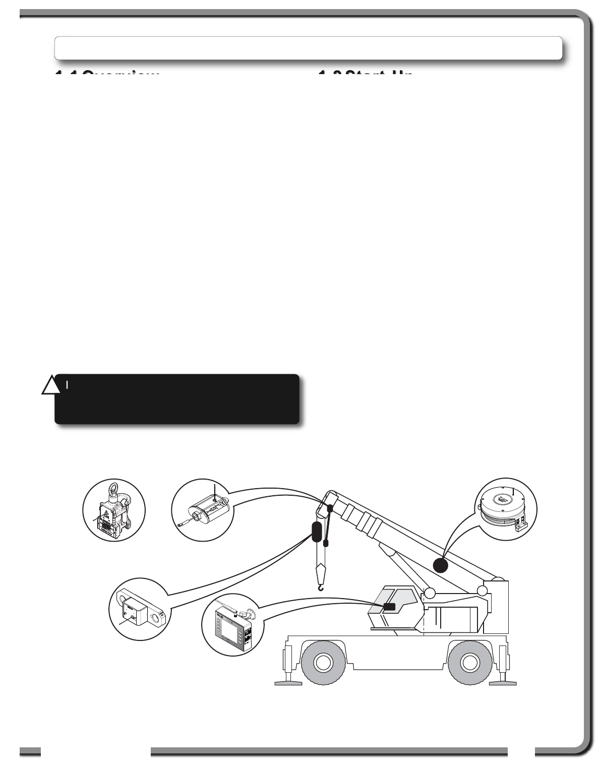
1.
1. INTRODUCTION
INTRODUCTION
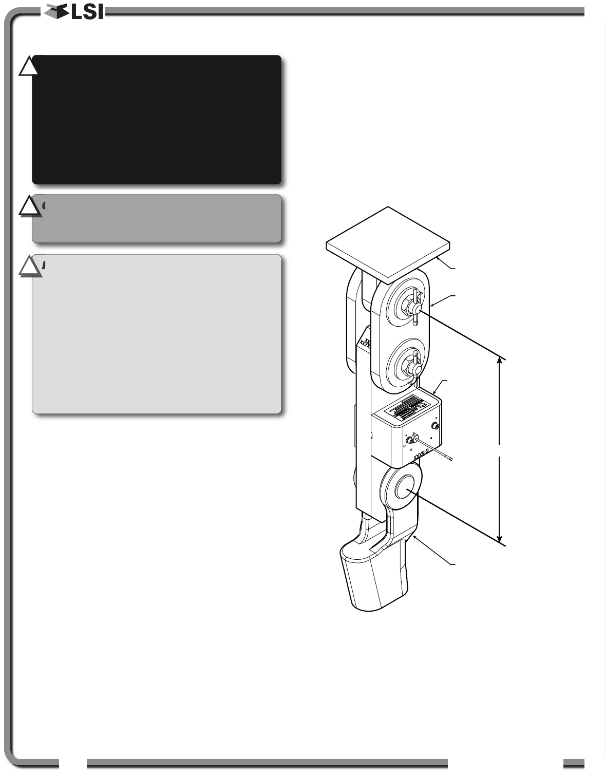
GS050 Anti-Two-
Block Switch
GS075 All-In-One
Anti-Two-Block
Switch and weight
GS101 Angle and
Length Sensor
GS820 Display
GC Series
Load Cell
Figure: Key components in a typical system installation. Your product may vary. Not to scale.
WARNING!
The GS820 system is designed
as an operator aid and is in no way a
substitute for safe operating practice.
!
!
6
6The GS820 System
The GS820 System
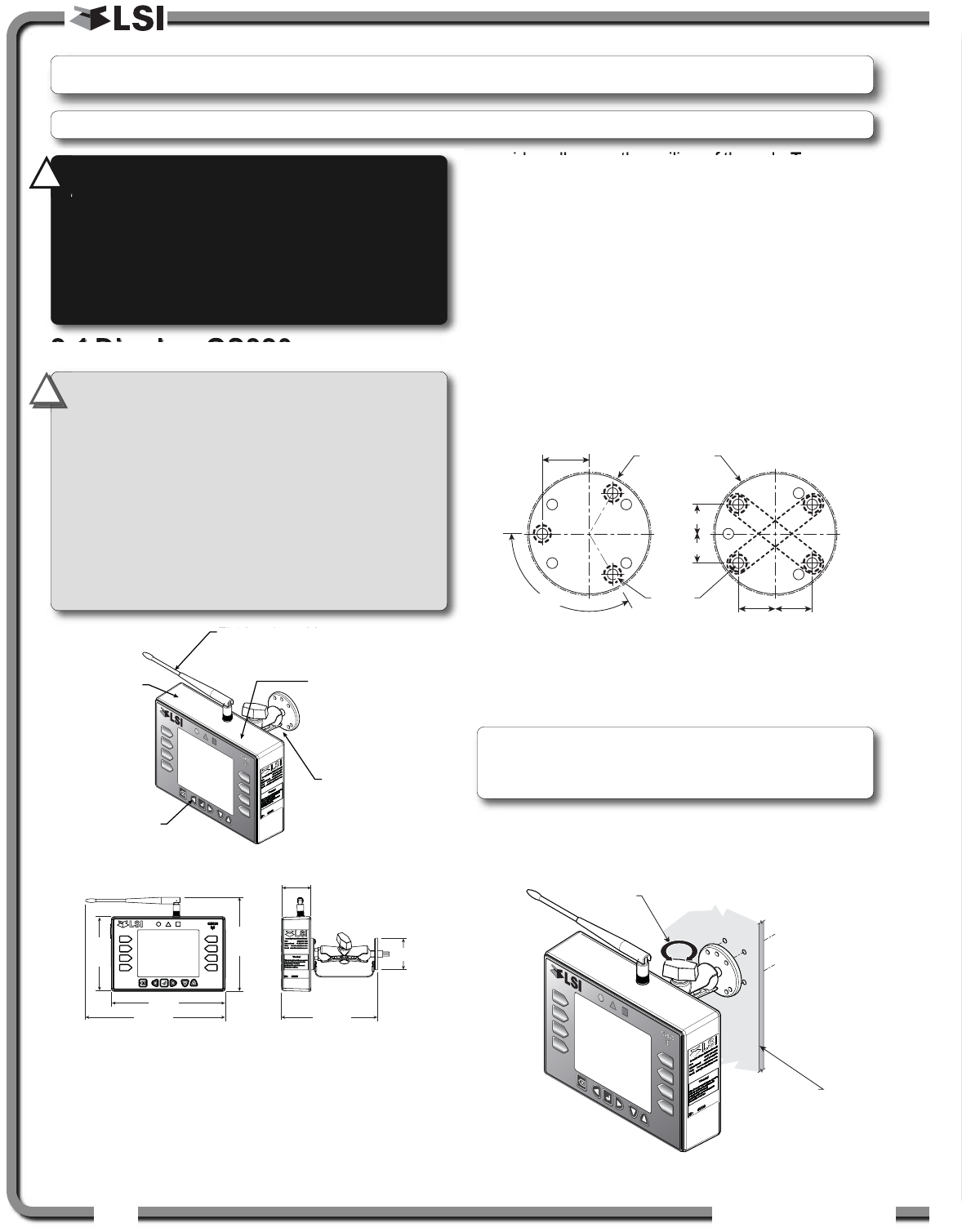
2.1
2.1 Display GS820
Display GS820
2.1a Mounting Bracket
1. Determine the mounting location; the display
may be installed either inside or outside the
cab. It can be mounted on the dash, on a
sidewall, or on the ceiling of the cab. To ensure
reliable radio communication between
sensors and the GS820, the antenna should
not be in contact with metal and should
have a direct and clear line of sight to the
sensor antenna. The mounting bracket
requires a flat surface of at least 2.5 inches in
diameter on both sides and where the back of
the surface is accessible in order to tighten the
nuts.
2. Drill 1/4 inch boltholes through the mounting
surface with a 1/4 inch bit following either the
two, three, or the four holes configuration.
3. Install the display with bolts. Add washers and lock
nut behind the mounting surface and tighten
sufficiently (bolts, nuts and washers not included).
4. Loosen the wing nut of the bracket arm to adjust
display orientation to facilitate viewing by the
operator and then tighten it back up.
2.
2. INSTALLATION
INSTALLATION
Cab mounting
surface
Wing
Nut
Figure: Display mounting bracket footprint. Not to scale.
Figure: Install the display and adjust orientation
10.73
8.75
7.37
7.23
2.44
2.25
Adjustable
Ram-Bracket
with dual ball joints.
Part number:
LB002B
Rugged
aluminium
enclosure
Two way radio
system
Waterproof
design
Field replaceable
antenna
Part number: TA008
5.74
Figure: Display GS820
Figure: Display dimensions (inches). Not to scale.
0.750 0.750
0.906
ø0.218
ø2.5 in. min.
flat surface
120° TYP
0.594
0.594
IMPORTANT!
Do not crack or puncture
the membrane fascia. The GS820 display is
splash and rain proof. Waterproofing depends in
part on the integrity of the membrane.
IMPORTANT!
Do not power wash the
display. The GS820 display is not designed to
withstand high-pressure washing devices that
can erode the membrane fascia seal or create
fissures in the membrane fascia. Power washing
the display voids warranty coverage.
!
!
Note: If the nuts are on the outside of the cab,
caulk with silicone between the washers and the
cab to prevent water entry.
WARNING!
Installation must be made in
compliance with LSI
LSI instructions and using
LSI
LSI supplied components only. Failure to
install all parts, or replacing parts or
components with parts or components not
supplied by LSI
LSI, may lead to system failure,
serious injury or death.
!
!
Note: Refer to the Operation section for detailed menu navigation instructions for all calibration procedures
ISTALLATIO
ISTALLATIO 7
7
2.1b Antenna Position
For optimal performance the antenna should be
positioned on its side such that it is parallel to
the sensor antennas (but not pointing directly to or
directly away from them).
1. Adjust the antenna position with the articulating base.
2. The antenna should have 5 inches of clear
space all around it.
3. The antenna should have an unobstructed line of
sight to all sensor antennas at all boom angles.
2.1c Power Supply and Lockout
Connection
1. Connect the black wire (ground) to the negative
terminal of the battery or the panel connection;
alternatively bolt the black wire to the body of
the machine with a 1/4 inch or 5/16 inch bolt.
The ground connection must be strong enough
to sustain 3 amperes.
2. Connect the red wire to a fused accessory
source, rated at least 3 amperes, that supplies
+12 or +24 volts when the machine is in use.
The GS820 will automatically detect the voltage
level and adjust itself.
3. Lockout number 1 (if required): connect the
white wire to a Bosch relay coil terminal.
Connect the other coil terminal of the relay to
the ground. When operating properly the white
wire will energize at the battery positive level.
Current over 1 ampere on the white wire
triggers an auto re-settable fuse. Current flow
will resume several seconds after the short
circuit is eliminated.
4. Lockout number 2, 3 and 4 (if required): these
wires function in the same way as the white wire
described in step 3 above. Each lockout wire
can be triggered by a different set of alarm
conditions; see the Lockout Settings sub
section of this manual.
5. Connect the yellow cable to the GS820. The
connector is waterproof and well rated for
external environments. Simply connect the
cable to the display and gently tighten the nut.
Do not put a kink in the yellow cable where
it enters the connector; any bend in the cable
at the base of the connector must not be so
severe as to break the internal connections
where the cable meets the connector. The
power cable requires about 4 1/2 in. behind
the display to protect the connector.
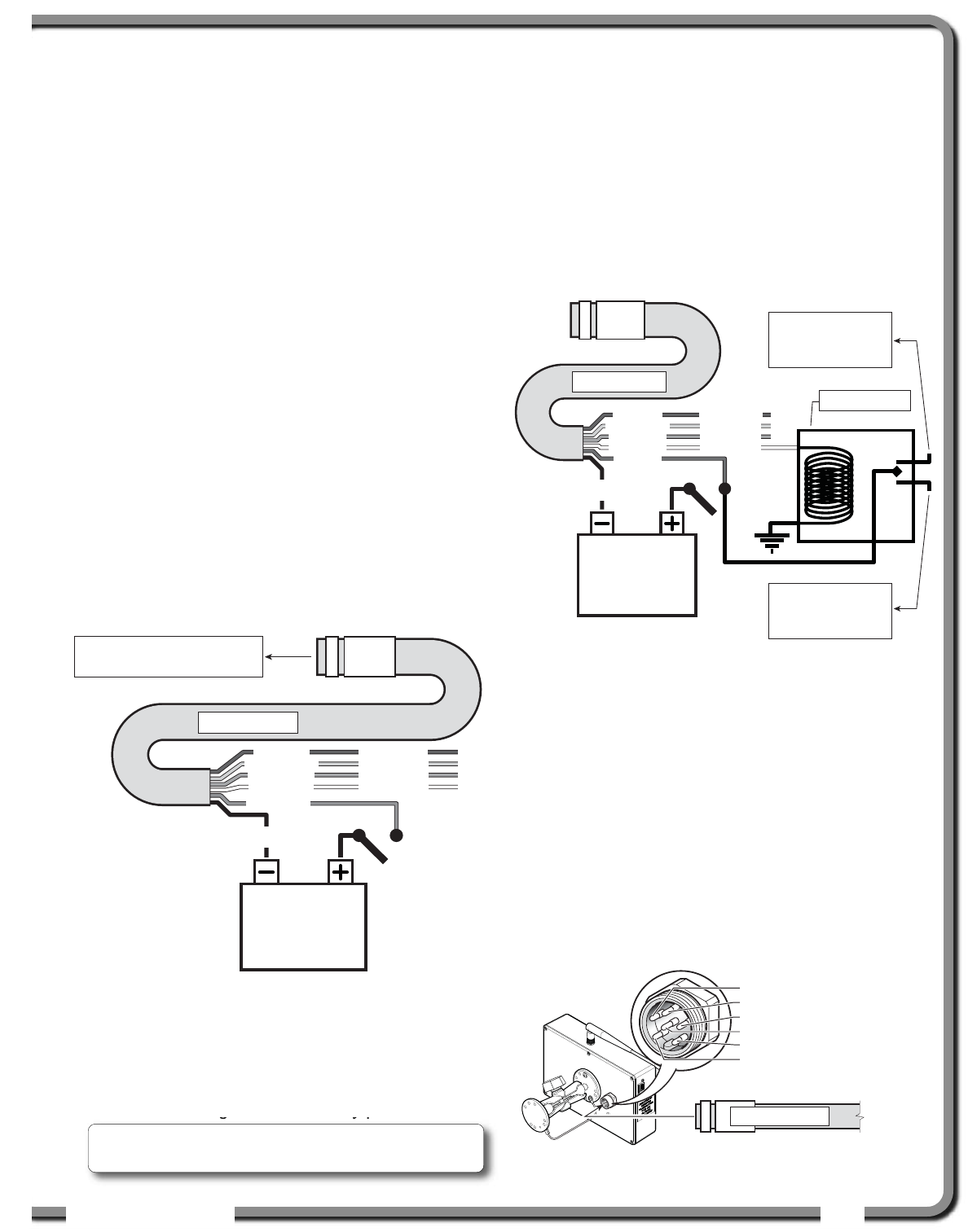
Power Supply
or Battery
+12 V or +24 V
Black
wire
Red wire
White wire
Orange wire
Green wire
Blue wire
Lockout #1
Lockout #2
Lockout #3
Lockout #4
Yellow cable
To GS820 power supply
connector (Step 5)
n.c.
n.o.
co
Power Supply
or Battery
+12 V or +24 V
Black
wire
Red wire
White wire
Orange wire
Green wire
Blue wire
Lockout #1
Lockout #2
Lockout #3
Lockout #4
To valve coil if
normally open is
required
Yellow cable
To valve coil if
normally closed
is required
Bosch relay
Yellow cable
Black wire: Negative (ground)
Red wire: Positive 12 or 24 volts
White wire: Lockout #1
Orange wire: Lockout #3
Green wire: Lockout #2
Blue wire: Lockout #4
Figure: Connection without lockout.
Figure: Connection with white wire lockout and recommended
Bosch relay.
Figure: GS820 power supply connector
Troubleshooting: if no voltage is present on the
white wire remove the load connected to the lockout.

8
8The GS820 System
The GS820 System
2.1d Lockout Settings
Warning, alarm and lockout control is programmed
in this menu. The GS820 can be programmed to
generate alarms and lockouts for almost all
programmed limits and two-block. Furthermore,
warnings are generated when approaching
programmed load limits and rated capacity (when
applicable).
Warning level. When gross load (regardless of
tare value) approaches the maximum limit for a
load sensor, an intermittent warning message is
generated on the LCD. The maximum limit for a
load sensor is the lower of; a) the operator set limit
(Limit Menu), and b) the working load limit (WLL) if
rated capacity charts are used. The proportion of a
limit that must be reached to trigger the overload
warning is the warning level. The default factory
setting for the warning level is 90%.
1. Go to menu 4G) LOCKOUT SETTINGS.
2. Enter the user password (using Back, Next, Up
and Down as described in Password settings
section) and press Enter.
3. Select 1) WARNING LEVEL and press Enter to
modify.
4. Use Up and Down to adjust the warning level
and press Enter to confirm any change.
3. Press Down to select 2) ALARM LEVEL or press
Exit to return to the operation display.
Alarm level. All programmed and rated capacity
limits and two-block will generate an audible alarm
when the alarm level is reached. Alarms will
generate an intermittent alarm message on the
LCD. The proportion of a limit that must be reached
to trigger an alarm is the alarm level. The default
factory setting for the alarm level is 100%.
1. In menu 4G), select 2) ALARM LEVEL and press
Enter to modify.
2. Use Up and Down to adjust the alarm level and
press Enter to confirm any change.
3. Press Down to select 3) LOCKOUT LEVEL or press
Exit to return to the operation display.
Lockout level. All programmed and rated capacity
limits and two-block can generate a lockout signal
when the lockout level is reached. By default the
lockout wires carry crane power supply voltage as
long as the display is in safe condition (to inverse
lockout polarity see menu 4G) 8) LOCKOUT RELAY
INVERTED). When a lockout level is reached voltage
is cut on all lockout wires linked to the lockout
condition (see menu 4G) 4) through 4G) 7)). The
proportion of a limit that must be reached to trigger
lockout is the lockout level. The default factory
setting for the lockout level is 105%.
1. In menu 4G), select 3) LOCKOUT LEVEL and press
Enter to modify.
2. Use Up and Down to adjust the lockout level
and press Enter to confirm any change.
3. Press Down to select 4) WHITE WIRE LOCKOUT
TRIGGER or press Exit to return to the operation
display.
Lockout triggers. Different events can be
programmed to cut voltage on the lockout wires of
the yellow cable. Each lockout wire can be linked to
a different combination of lockout conditions.
1. In menu 4G), select 4) WHITE WIRE LOCKOUT
TRIGGER and press Enter to modify.
2. Select which alarm conditions will trigger
lockout on the white wire (see tables below).
3. Add the lockout codes for the selected alarms
together to find the lockout trigger number.
4. Use Up and Down to adjust the white wire
lockout trigger number and press Enter to
confirm any change.
5. Press Down to select the next wire trigger line
and repeat steps 1 through 5, or, press Exit to
return to the operation display.
Table: Default Triggers
Lockout Wire Default Trigger
White . . . . . . . . . . . . . . . . . . . . . . . . . . . . 4301
Green . . . . . . . . . . . . . . . . . . . . . . . . . . . . . . 34
Orange . . . . . . . . . . . . . . . . . . . . . . . . . . 32767
Blue . . . . . . . . . . . . . . . . . . . . . . . . . . . . . . . . 0
Table: Lockout Codes
Condition Code
Maximum wind speed . . . . . . . . . . . . . . . . . . 1
Minimum angle. . . . . . . . . . . . . . . . . . . . . . . . 2
Maximum angle . . . . . . . . . . . . . . . . . . . . . . . 4
Overload . . . . . . . . . . . . . . . . . . . . . . . . . . . . 8
Not used. . . . . . . . . . . . . . . . . . . . . . . . . . . . 16
Maximum radius. . . . . . . . . . . . . . . . . . . . . . 32
Maximum length. . . . . . . . . . . . . . . . . . . . . . 64
Two-block. . . . . . . . . . . . . . . . . . . . . . . . . . 128
Maximum wind gust . . . . . . . . . . . . . . . . . . 256
Maximum rope payout . . . . . . . . . . . . . . . . 512
Minimum slew . . . . . . . . . . . . . . . . . . . . . 1024
Maximum slew . . . . . . . . . . . . . . . . . . . . . 2048
Maximum tip height . . . . . . . . . . . . . . . . . 4096
Maximum imbalance factor . . . . . . . . . . . 8192
ISTALLATIO
ISTALLATIO 9
9
Table: Lockout Codes (Continued)
Condition Code
Minimum slack rope . . . . . . . . . . . . . . . . 16384
Minimum list angle . . . . . . . . . . . . . . . . . 32768
Maximum list angle . . . . . . . . . . . . . . . . 65536
Minimum trim angle . . . . . . . . . . . . . . . 131072
Maximum trim rope . . . . . . . . . . . . . . . 262144
Minimum mast radius. . . . . . . . . . . . . . 524288
Maximum mast radius . . . . . . . . . . . . 1048576
Minimum load limit . . . . . . . . . . . . . . . 2097152
Table: Example № 1
Maximum radius. . . . . . . . . . . . . . . . . . . . . . 32
Minimum angle . . . . . . . . . . . . . . . . . . . . . . + 2
Default green wire trigger . . . . . . . . . . . . . = 34
Table: Example № 2
Maximum wind speed . . . . . . . . . . . . . . . . . . 1
Maximum angle . . . . . . . . . . . . . . . . . . . . . . . 4
Overload . . . . . . . . . . . . . . . . . . . . . . . . . . . . 8
Maximum length. . . . . . . . . . . . . . . . . . . . . . 64
Two-block. . . . . . . . . . . . . . . . . . . . . . . . . . 128
Maximum tip height. . . . . . . . . . . . . . . . + 4096
Default white wire trigger . . . . . . . . . . . = 4301
Lockout relay inversion. By default the lockout
wires carry crane power supply voltage as long as
the display is in safe condition. When lockout is
triggered voltage is cut on the lockout wires linked
to the lockout condition.
Exceptionally the lockout relay can be inverted so
that lockout wires carry no voltage in safe condition
and carry crane power supply voltage when in a
triggered lockout condition. In this case if the
display fails, crane functions will not lockout.
1. In menu 4G), select 8) LOCKOUT RELAY INVERTED
and press Enter to modify.
2. Use Up and Down to switch between “YES” and
”NO” and press Enter to confirm any change.
3. Press Exit to return to the operation display.
2.1e Password Settings
Two levels of access are available: administrator
and user. The administrator password is required
to change the user password. In the event both the
administrator and the user passwords are lost
please call LSI
LSI technical support. Menus
accessible from the operation display can be
individually protected by the user password.
1. Go to menu 4) INSTALLATION and select 4H)
PASSWORD SETTINGS.
2. Enter the administrator password and press
Enter.
3. Select 1) ADMINISTRATOR PASSWORD and press
Enter to modify.
4. Use Up and Down to adjust the administrator
password. Press Enter to save any changes.
5. In menu 4G), select 2) USER PASSWORD and press
Enter to modify.
6. Use Up and Down to adjust the administrator
password. Press Enter to save any changes.
7. In menu 4G), select 3) TARE PROTECTED and
press Enter to modify.
8. Use Up and Down to switch between “YES” and
“NO” and press Enter to save any changes.
9. Repeat steps 7 and 8 to adjust password
protection for each menu as required. Press
Enter at any time to save changes made. Press
Exit at any time to return to menu 4)
INSTALLATION. If there are any unsaved changes
the display will request confirmation: press
Enter to save before quitting or press Exit to
quit without saving.
WARNING!
Inverting lockout relays will
allow crane operation in the event the GS820
display fails. Operating a crane without a
functioning anti-two-block system and load
and angle indication is dangerous and may
be against the law.
!
!
10
10 The GS820 System
The GS820 System
2.2
2.2 Load Cell
Load Cell
1. Install load cell bushings as supplied by LSI
LSI.
Assembly of the load cell and adapter plates
must be configured to the pin size required by
the specific dead end or hook to which it is to be
attached. In all cases, the bushings supplied by
LSI
LSI must be used where possible to adapt the
holes in the load cell to the pins. Bushings must
be secured with the two allen screws provided,
one on each side of the load cell.
2. As required, place a washer between adapter
plate and pin head or nut on each end of the pin
that links the adapter plates to the load cell.
Additional washers should be added equally to
each end of the pin as required to inhibit
excessive lateral movement of load cell
(maximum 1/8” total movement) and adapter
plates along the pin.
3. If the dead end or hook to be connected to the
adapter plates requires a larger opening,
washers may be placed between the load cell
and the adapter plates equally on both sides of
the load cell.
4. In all cases the washers must be placed
symmetrically such that the load cell is centered
on the pins to avoid uneven loading.
5. Secure the pins with the nuts and cotter pins
provided.
6. A qualified (lift supervisor or crane inspector)
person must verify every lift assembly before
first use and periodically thereafter (one to
twelve months), including before any new,
difficult or otherwise different lift.
Crane dead
end
Plate kit for
loadlink
Loadcell
Wedge socket
to loaded cable
C/C
Figure: Typical load cell and adapter plate assembly installed.
IMPORTANT!
The load cell antenna should
not be in contact with metal.
IMPORTANT!
For optimal performance and
signal reception, the GS820 load cell antenna
should have a clear line of sight to the
GS820 display.
IMPORTANT!
The load cell antenna should
point to the left or to the right of the boom; it
should not point directly to, or away from, the
GS820 display.
WARNING!
Capacity and safety factor for
load cells and adapter plate assemblies are
calculated for load along the intended axis of
load (vertical with the assembly hanging
free); side loading may cause load cell and
adapter plate assembly to fail, causing load to
drop. Lifts must be rigged such that the load
cell and adapter plate assembly hang free and
not be subjected to side loading.
!
!
!
!
CAUTION!
The load cell must be centered
on the pins to avoid uneven loading on the
plate kit assembly.
!
!
ISTALLATIO
ISTALLATIO 11
11
2.3
2.3 Angle Sensors
Angle Sensors
2.3a Mounting Procedure
The GS010 series angle sensors can be turned on
by starting up the GS820 display to which they are
programmed. The angle sensor can then assist in
levelling itself with the red and green LED.
1. Determine the angle sensor position.
a. The GS010-01 boom angle sensor can
be mounted on either side of the boom.
b. The GS010-02 360° angle sensor must
be mounted on the port side of the jib.
c. The angle sensor must be level with the
boom or jib centerline.
d. The top / bottom axis of the angle sensor
must be within 15 degrees of vertical
e. The angle sensor should have a clear line
of sight to the cabin mounted display.
f. The angle sensor antenna should not
contact a metal object.
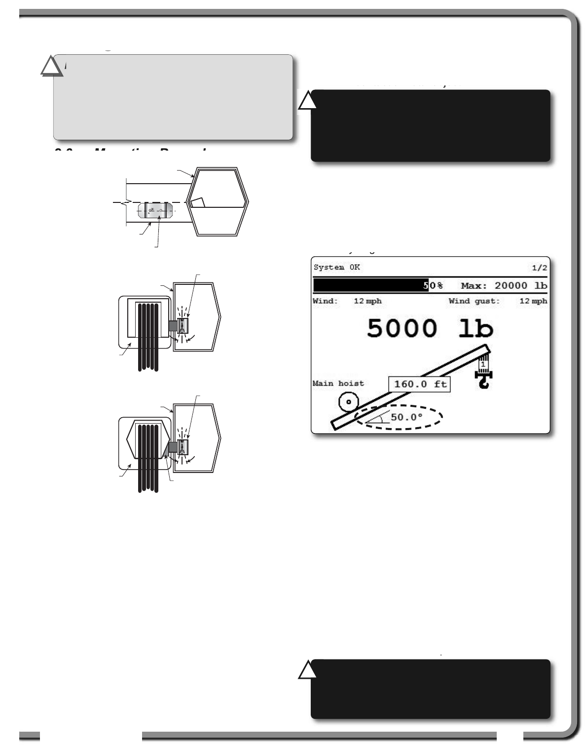
2. Install the welding pads; keep the angle sensor
at least three feet from the weld site and any
connecting metal objects while welding.
3. Mount the angle sensor to the weld pads with
the screws and washers provided.
4. Verify angle indication on the GS820 LCD.
5. If the angle displayed by a GS010-01 boom
angle sensor is a high negative value, then tilt
the angle sensor up over 45 degrees, and then
tilt back down to horizontal. The GS010-01
boom angle sensor will automatically detect on
which side of the boom it is installed and correct
angle indication accordingly.
2.3b Angle Calibration Procedure
№ 1: Mechanical Set-Up
1. Level the boom such that it is perfectly
horizontal; use a high quality bubble or digital
angle sensor. If the GS820 display indicates 0.0
degrees then angle calibration is complete; if
not then continue to step 2.
Cabin
Boom
Angle Sensor
Boom
C
L
Boom
Angle Sensor
Cabin
Boom
Angle Sensor
Cabin
Wedge
Figure: Angle sensor level with the boom (typical installation) -
Side View
Figure: Angle sensor top/bottom axis within 15° of vertical
(typical installation) - Front View
Figure: Wedge used to mount the angle sensor with its
top/bottom axis within 15° of vertical (typical
installation) - Front View
Figure: Typical operation page with boom angle indication
IMPORTANT!
Keep the angle sensor away
from the boom and any connecting metal
structures when welding the metal lugs to the
boom. Proximity to welding may cause
permanent damage to the angle sensor and
prevent accurate angle indication.
!
!
WARNING!
The angle reading may be
affected by vibration and may fluctuate; the
angle sensor should not be installed in close
proximity to a high RPM electric motor or other
source of high frequency vibration.
!
!
WARNING!
Failure to ensure the boom is
levelled will result in false reading of the
crane’s radius hence the risk of structural
failure of the crane or crane tipping over.
!
!
12
12 The GS820 System
The GS820 System
2. For GS011 angle/length sensors only: Carefully
remove the cover of the GS101 cable reel.
3. Loosen the mounting screw in the slotted hole
of the angle sensor mounting plate.
4. Pivot the angle sensor slightly until angle
indication is correct. Repeat the angle validation
(step 1) as required.
2.3c Angle Calibration Procedure
№ 2: Correct with the GS820
Calibrate angle indication by adjusting the trim (offset)
value in the GS820 display; the GS820 will then
communicate the updated trim value to the sensor.
1. Position the boom at a precisely known angle.
2. Go to menu 4) and select 4B) SENSOR CALIBRATION.
3. Enter the user password and press Enter.
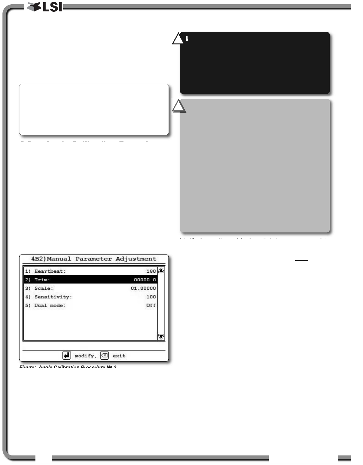
4. Select 4B2) MANUAL PARAMETER ADJUSTMENT.
5. Use Up and Down to select the angle sensor
to be calibrated and press Enter.
6. Select 2) TRIM:and press Enter to modify.
7. Use Up and Down to modify the trim value.
Example: If angle indicated is 0.3° over the actual
angle, adjust the trim value to -0.3.
Example: If angle indicated is 0.9° below the actual
angle, adjust the trim value to 0.9.
8. Press Enter to save changes.
9. Press Exit to return to the operation display.
10.Verify accurate angle indication at both very
high and very low angles.
2.4
2.4 Anti-Two-Block Switch
Anti-Two-Block Switch
Verify the anti-two-block switch is programmed to
the GS820 display. Switches shipped with displays
are pre-programmed in the factory. Test: if the
switch has been programmed to the display then
the display will go in to two-block alarm when the
wire rope of the switch is released. Press Bypass
to silence the alarm until the next two-block event
or simulation. If the switch has not been
programmed to the display, this should be done
before proceeding with installation. See the section
How to Add a Sensor to the GS820.
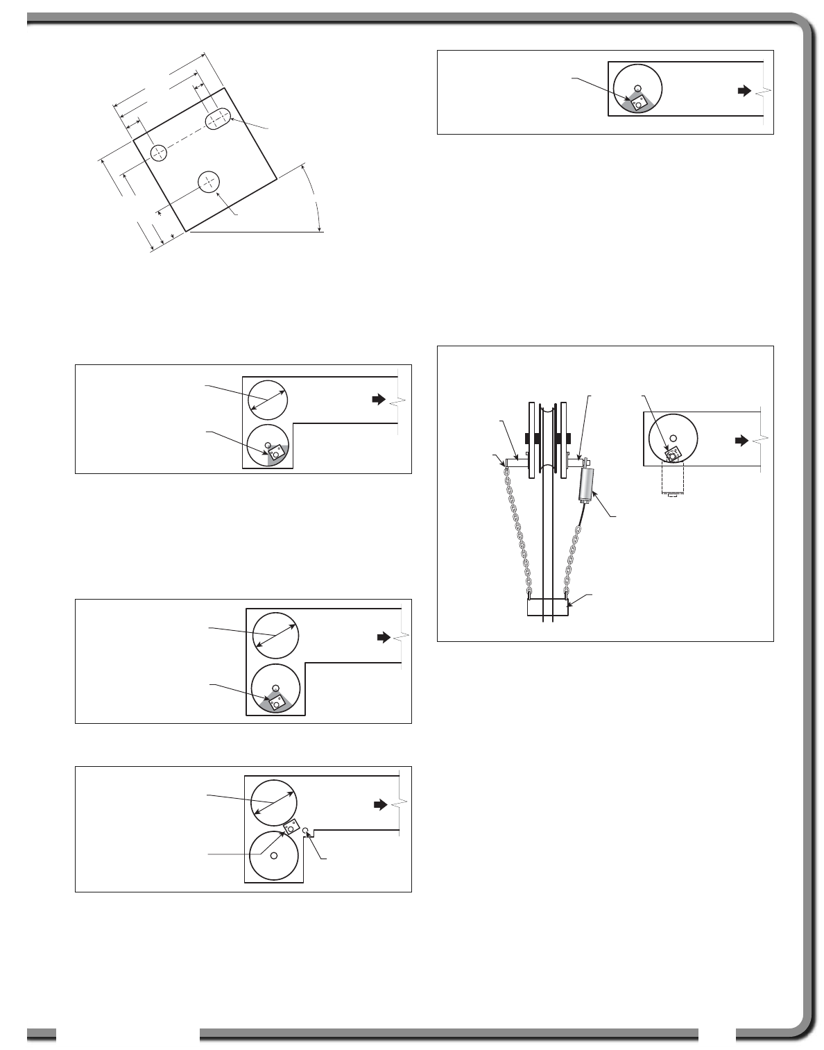
2.4a GS050 Installation
1. Position the sensor mounting bracket. To
ensure that the sensor can pivot securely on the
mounting bracket throughout the full range of
boom angle, the mounting bracket must be
positioned at a 30° from horizontal with the
boom parallel to the ground and such that the
locking pin of the mounting bracket points up.
Bolt or weld securely.
Figure: Angle Calibration Procedure № 2
Note: When the angle sensor is moved very slowly,
it may take several seconds to see an update at the
GS820 display. Instead move the sensor up a couple
of degrees, and then bring it back down to where it
should be. The small light on the angle sensor
flashes when it transmits a new value to the display.
WARNING!
Keep the anti-two-block switch
away from the boom and any connecting
metal structures when welding mounting
brackets to the boom. Proximity to welding
may cause permanent damage to the anti-
two-block switch and render the anti-two-
block system unsafe.
!
!
IMPORTANT!
To ensure reliable radio
communication between the anti-two-block
switch and the GS820 display the following
conditions must be respected:
• The antenna of the anti-two-block switch
should not be in contact with metal.
• The anti-two-block switch antenna should
point to the left or to the right of the boom;
it should not point directly to, or away from,
the GS820 display.
• The anti-two-block switch antenna should
have a clear line of sight to the GS820
display; in most cases this means mounting
the sensor on the same side of the boom as
the operator's cab.
!
!
ISTALLATIO
ISTALLATIO 13
13
If the head sheave diameter is between 8 and 16
inches (20-41 centimetres) then two mounting
brackets will be required to permit both live and dead
end mounting.
For live end mounting on multiple sheave blocks
with sheaves greater than 16 inches (41
centimetres) in diameter consult your service
representative.
For fast line weight installation place the anti-two-
block switch mounting bracket directly below the
sheave center as low and as close to the edge of
the sheave as possible. Place the fast line weight
mounting bracket on the opposite side of the
sheave with the chain hole pointing down and lined
up opposite the pivot of the anti-two-block switch
mounting bracket.
2. Mount the GS050 on the bracket and verify that
the GS050 can rotate freely through all possible
boom movements without being able to come
off the bracket.
3. Install the weight and chain assembly around
the cable and attach the other end of the chain
to the GS050. Tighten all the chain links of the
chain assembly.
4. Adjust chain length as required, see sub-section
Chain length adjustment.
5. Test system function.
ø0.38
Pivot Center
(Anchor shaft)
30°
2.50
2.125
0.375 0.25
2.5
1.9375
0.75
Up to 8 in. (20 cm)
diameter Boom
base
Mount bracket below
and behind sheave
center.
Figure: Anti-two-block switch placement on a telescopic boom
8-16 in. (20-41 cm)
diameter Boom
base
Mount bracket 4 in.
(10 cm) below sheave
center.
Figure: Anti-two-block switch placement for live end mounting
on a lattice boom
8-16 in. (20-41 cm)
diameter Boom
base
Dead
end pin
Mount bracket 4 in.
(10 cm) in front of the
dead end pin.
Figure: Anti-two-block switch placement for dead end
mounting on a lattice boom
Boom
base
Mount bracket 4 in.
(10 cm) below sheave
center.
Figure: Jib, rooster or other extension; anti-two-block switch
placement for single part of line operation only
Boom
base
Mount bracket directly
below sheave
center as low as
possible.
Fast line
mounting
bracket
Fast line
weight
Anti-two-block
switch GS050
Front View
Chain
hole
Figure: Fast line weight installation
Figure: Bracket footprint and orientation,
All dimensions are in inches. Not to scale.
14
14 The GS820 System
The GS820 System
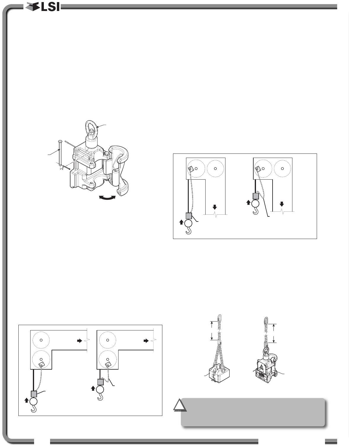
2.4b GS075 Installation
1. Optional Bracket: Position the optional mounting
bracket on the boom. Bolt or weld securely.
2. Attach one end of the chain assembly to the
optional bracket or to the boom and the other
end to the eye bolt of the GS075. Tighten all the
chain links of the chain assembly.
3. Remove the hair pin and the clevis pin and
open the back end of the GS075. Install the
GS075 around the cable and then put the clevis
pin back in.
4. Adjust chain length as required, see sub-section
Chain length adjustment.
5. Test system function.
2.4c Chain length adjustment
1. Chain length adjustment № 1 – minimum boom
angle
a. At minimum boom angle, with no
additional weight on the hook block and
one part of line only, lift the boom just
enough to have the hook block suspend
and clear the sensor chain and weight.
b. Hoist slowly until the buzzer sounds. Note
the hoisting distance remaining; this
distance must be great enough to allow
the operator and the lockout system, if
installed, to prevent a two-block event. If
necessary, add chain between the sensor
and weight to increase warning distance.
If still insufficient, contact your service
representative.
2. Chain length adjustment № 2 – maximum boom
angle
a. Raise the boom to the maximum angle.
b. Hoist slowly as described in Step 1.b. Verify
that the warning distance is equal to or
greater than that determined at the
minimum boom angle.
3. Chain length adjustment № 3 – speed test:
Lower the boom until the weight height becomes
visually clear to the operator. Repeatedly create
two-block, progressively hoisting faster, to
ensure that the warning and lockout work within
acceptable amount of time and distance.
Increase the length of the chain if needed.
B) Hook block stops
rising, two-block
prevented with
safety margin
Boom
base
A) Anti-two-block
switch triggers
two-block alarm
Boom
base
Figure: Chain length test at minimum angle
B) Hook block stop
s
rising, two-block
prevented with
safety margin
Boom
base
A) Anti-two-block
switch triggers
two-block alarm
Boom
base
Figure: Chain length test at maximum angle
GS075
Increase Increase
GS050
weight
Figure: Chain length adjustment
Eye bolt
Clevis pin
Figure: Install the GS075 around the cable
IMPORTANT!
GS050: to increase chain length, only use
lightweight chain.
!
!
ISTALLATIO
ISTALLATIO 15
15
2.5
2.5 Length Sensor Cable Reel
Length Sensor Cable Reel
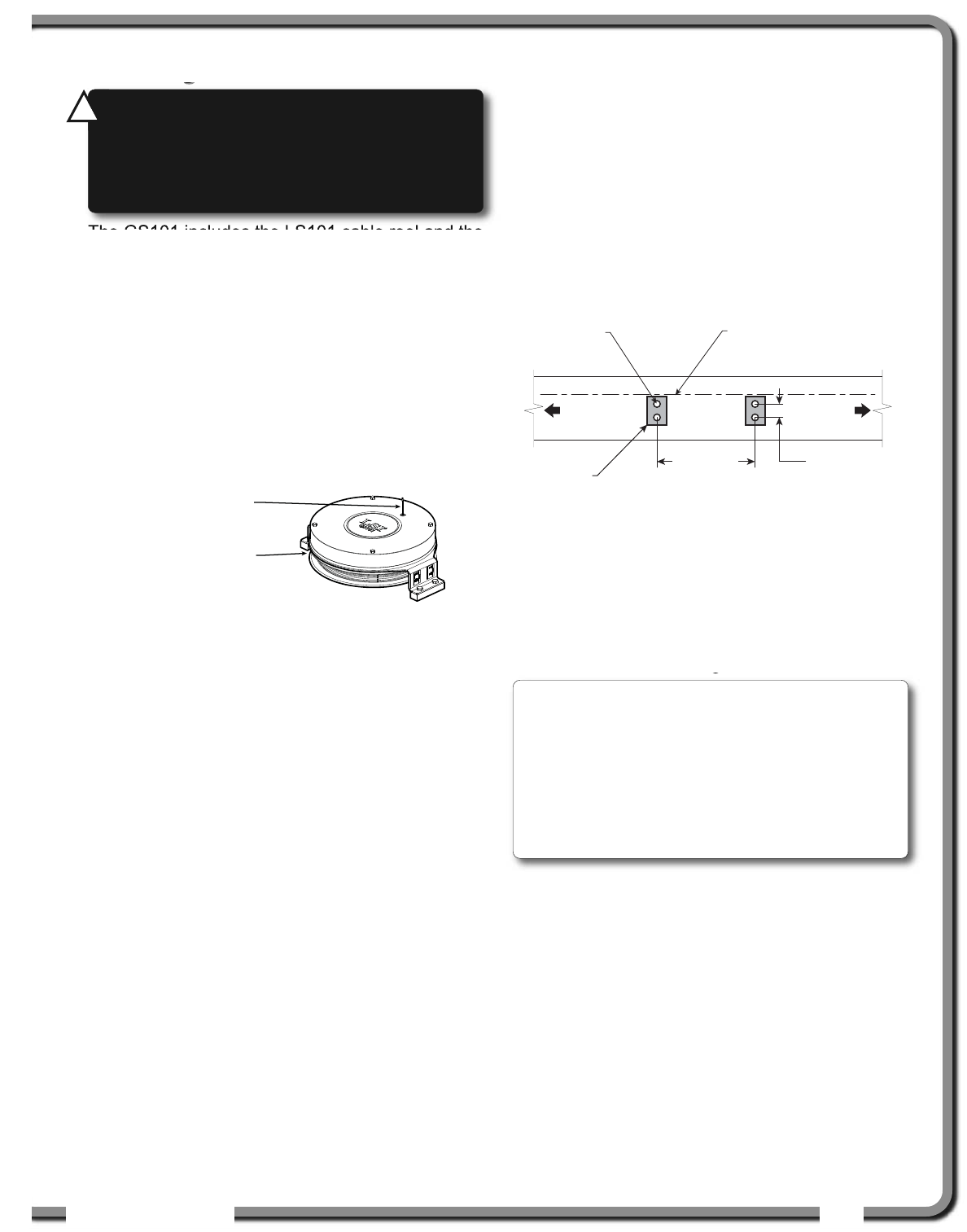
The GS101 includes the LS101 cable reel and the
GS011 angle/length sensor. The GS011 is
concealed under the cover of the LS101, though
the antenna is visible. Following cable reel
installation and boom length indication calibration,
boom angle indication will have to be verified and
possibly calibrated. Refer to Angle Calibration
Procedure № 1: Mechanical Set-Up and Angle
Calibration Procedure № 2: Correct with the
GS820, sections of this manual.
2.5a Maximum Boom Extension
Confirm the maximum extension of the LS101 cable
reel is compatible with the maximum boom length.
Step 1. Note the cable reel maximum extension: 100 feet
(30.5 metres) unless specified otherwise.
T = ____________________
Step 2. Note the retracted boom length.
A = ____________________
Step 3. Note the maximum extended boom length, not
including jib.
B = ____________________
Step 4. Calculate maximum boom extension.
C = B – A =____________________
Step 5. Compare cable reel maximum extension (T) to
maximum boom extension (C).
D = T – C =____________________
Maximum cable reel extension must be greater
than maximum boom extension.
2.5b Mounting the Cable Reel
1. Determine placement. Find a clear mounting
position on the left side of the first (main) section
of the boom. The mounting position should be
close to the base of the boom; at least ten feet
(three metres) from the tip of the first section and
where the cable reel won’t obstruct free boom
movement at all boom angles and slew positions.
Furthermore, the reel must be placed such that
the cable has a clear straight line to the end of
the last section at all boom lengths.
2. Mount the welding tabs. They must be placed
parallel to each other, with 16 1/8” inches
between the holes’ centres. Install the tabs such
that they create a level mounting position in line
with the boom at 0 degrees.
3. Attach the reel to the welding tabs with the bolts
provided.
4. Install the first cable guide (PA111) about 10 feet
(3 metres) from the cable reel. Correct alignment
of the first guide is critical to ensure orderly
winding of the cable on the reel. Install the other
guides at the end of each of the intermediate
sections and the anchor (PA113) at the end of the
last section. All guides must be aligned so as to
permit unobstructed movement of the cable.
5. Pull out at least 5 feet (1-1/2 metres) of cable,
but not more than half the excess extension of
measurement D. Feed through the cable guides
GS011 angle/length
sensor antenna
LS011 length sensor
cable reel
Figure: GS101 angle & length sensor
Boom
base
Boom
tip
Welding
pads holes
16 1/8 in. apart,
centre-to-centre
Welding
pad holes
2 1/4 in. apart,
centre-to-centre
Welding
pads
Welding
pad holes
tapped 3/8-16
Welding pads level and
in line with the boom at
0 degrees from horizontal
Figure: Cable reel mounting position
WARNING!
Arc welding may damage LSI
LSI
sensors, causing immediate failure or greatly
reducing functional life. Arc welding on or near
LSI
LSI equipment will void warranty. Keep LSI
LSI
equipment well clear of any arc welding.
!
!
Note: When factory installed the GS011
angle/length sensor transmitter is integrated to the
LS101 cable reel with the angle sensor zeroed. If
the cable reel is installed perfectly level on the
boom at 0 degrees, the angle sensor of the GS011
will also be zeroed. Minor adjustments to the angle
sensor (within plus or minus two degrees) are
possible after cable reel installation.
16
16 The GS820 System
The GS820 System
and attach to the cable anchor on the tip of the
last boom section. If additional cable length is
required to reach the cable anchor point remove
winds from the reel without putting additional
tension on the cable reel spring. There should be
minimal tension on the cable reel spring when the
boom is fully retracted.
6. Verify the boom length indicated on the GS820
LCD. Boom length indicated should equal the
actual total boom length. The actual boom length
is the distance from the boom base pin to the head
sheave centre as measured along the boom
centreline. Depending on the exact placement of
the cable reel and the cable anchor the displayed
length may differ from the actual length.
2.5c Boom Length Calibration
Procedure № 1: Mechanical
Set-Up
1. Fully retract the boom
2. Adjust the loose wire rope at the boom tip so
that the displayed boom length matches the
actual boom length.
3. Fully extend the boom
4. Verify the boom length indicated at full boom
extension matches the actual fully extended boom
length. If not then follow Boom Length Calibration
Procedure № 2: Correct with the GS820.
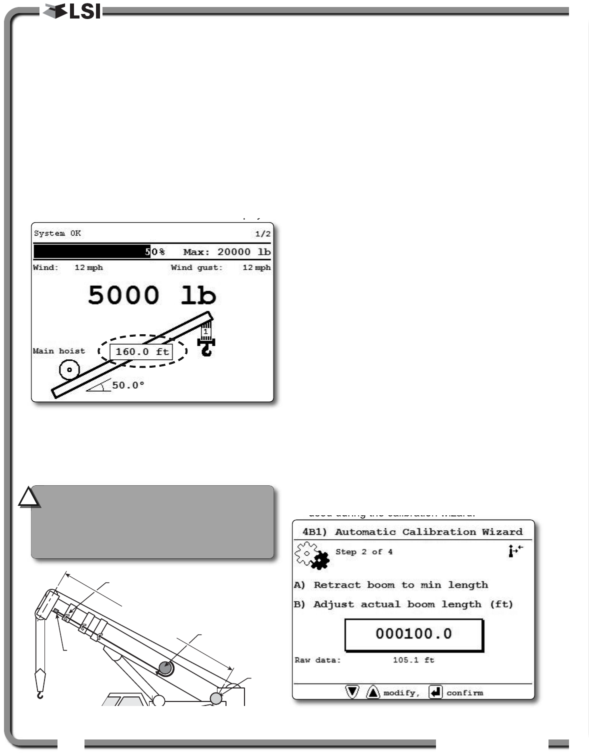
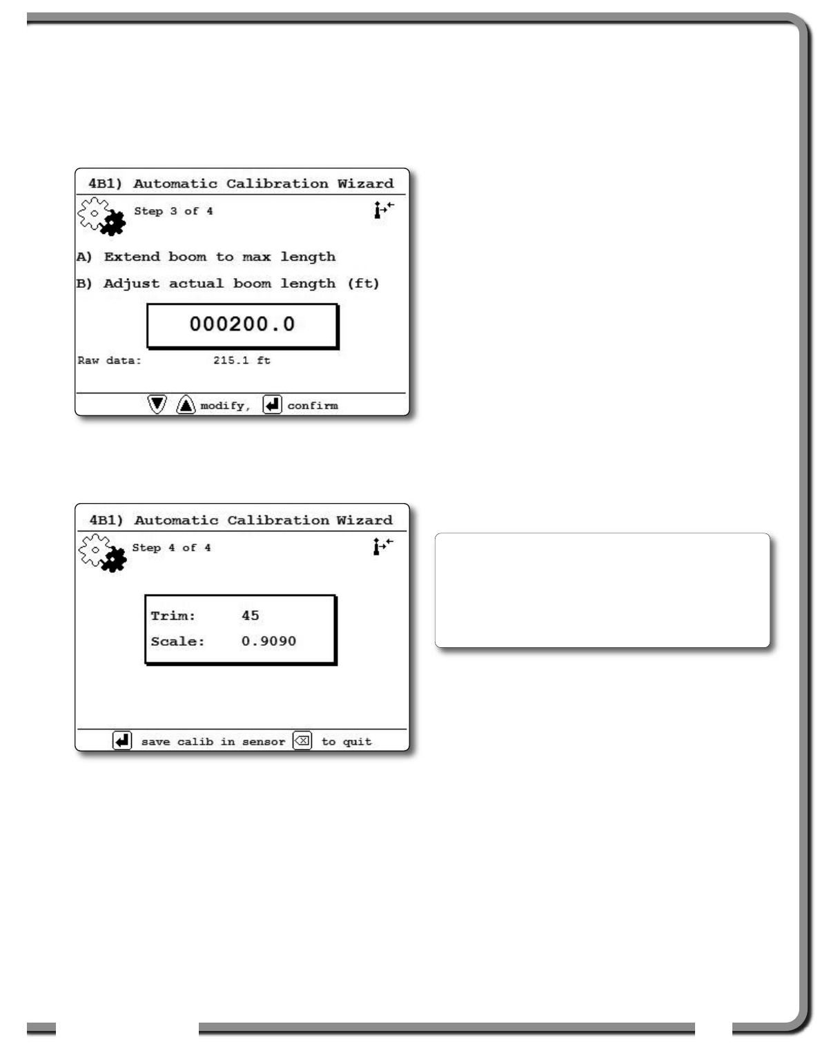
2.5d Boom Length Calibration
Procedure № 2: Correct with
the GS820
If the displayed boom length does not match the
actual length of the boom retracted or extended and
if it is not possible to easily correct by following 2.6c
Boom Length Calibration Procedure № 1, then
follow this procedure. This procedure is completed in
the operators cab, it requires fully retracting, and
then fully extending the boom, as prompted by the
on screen instructions.
1. Go to menu 4) INSTALLATION and select 4B)
SENSOR CALIBRATION.
2. Enter the user password, press Enter and go to
menu 4B1) AUTOMATIC CALIBRATION WIZARD.
3. Use Up and Down to select the length sensor,
and then press Enter to confirm communication
with the sensor is possible.
4. Start the wizard.
5. Press Enter to confirm the units that will be
used during the calibration wizard.
Cable
anchor
Cable guide
Cable
reel
Boom length
Boom
base
pin
Figure: The actual boom length. Typical installation.
Figure: Typical operation page with boom length indication
Figure: The boom length calibration wizard, confirm minimum
boom length.
CAUTION!
Visually monitor remaining
length on the cable reel as the boom is
extended for the first time following
installation. This generally requires a second
person (in addition to the operator).
!
!
ISTALLATIO
ISTALLATIO 17
17
6. Fully retract the boom, and use Up and Down
to adjust the length value displayed to equal the
actual fully retracted boom length, and then
press Enter to confirm.
7. Fully extend the boom, and use Up and Down
to adjust the length value displayed to equal the
actual fully extended boom length, and then
press Enter to confirm.
8. Note the new trim and scale values.
9. Press Enter to send the new calibration to the
length sensor.
10.Press Exit to return to the operation display.
2.6
2.6 Radius
Radius
2.6a Radius Verification and
Adjustment
1. Verify the boom and luffing jib* angles, and the
boom length**, are indicated correctly.
2. Verify the correct rated capacity chart is
selected***.
3. Test № 1: measure the actual radius and
compare to the radius indicated. Repeat with
the boom at minimum angle, at 45 degrees, and
at maximum angle; repeat at minimum and
maximum boom length**. If radius indication is
not accurate then go to step 4.
4. Measure the basic radius parameters on the
crane.
5. Program the basic radius parameters in the
RADIUS SETTINGS menu.
6. Test № 2: measure the actual radius and
compare to the radius indicated. Repeat with the
boom at minimum angle, at 45 degrees, and at
maximum boom angle; repeat at minimum and
maximum boom length**. If radius indication is
not accurate then go to the next step.
7. If the crane is rigged with the main boom only,
then go directly to step 11.
8. If the crane is rigged with a rooster, jib, or other
extension then the advanced radius parameters
must be measured on the crane and then
programmed in the RADIUS SETTINGS menu of the
display.
9. Test № 3: measure the actual radius and
compare to the radius indicated. Repeat with the
boom at minimum angle, at 45 degrees, and at
maximum boom angle; repeat at minimum and
maximum boom length**. If radius indication is
not accurate then go to the next step.
* When the hoist is rigged off of a luffing jib only
** Telescopic boom cranes only
*** Systems with rated capacity charts programmed
in the GS820 only
Figure: The boom length calibration wizard, confirm maximum
boom length.
Figure: The boom length calibration wizard, Trim and Scale
values.
Note: If the difference between the displayed
radius and actual radius remains constant at all
boom lengths and angles, then correct by adjusting
the slew offset. For example: if the radius displayed
is always 2.3 feet longer than the actual radius,
then subtract 2.3 from the slew offset.
18
18 The GS820 System
The GS820 System
10. Test for boom deflection (telescopic crane only):
is the radius indicated equal to the actual radius
with the boom at 0 degrees and at 90 degrees
but smaller than the actual radius with the boom
at 45 degrees? If yes then adjust the boom
deflection value to compensate:
a. Raise the boom to 45 degrees with a
known load.
b. Compare the indicated radius with the
actual radius. Change the boom
deflection value and again compare the
radius displayed with the actual radius.
Repeat until the radius displayed equals
the actual radius.
11. Test № 4: measure the actual radius and
compare to the radius indicated. Repeat with the
boom at minimum angle, at 45 degrees, and at
maximum boom angle; repeat at minimum and
maximum boom length**. If radius indication is
not accurate then refer to Radius Settings.
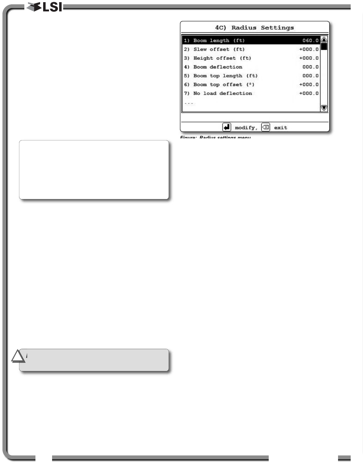
2.6b Radius Settings
1. Go to menu 4) INSTALLATION and select 4C)
RADIUS SETTINGS.
2. Enter the user password and press Enter.
3. Use Up and Down to navigate between the
radius settings, press Enter to modify and use
Up and Down to adjust the settings.
4. Press Enter to save any changes and press
Exit to return to the operation display.
4C) RADIUS SETTINGS
*1) Boom length
*2) Slew offset
3) Height offset
4) Boom deflection
5) Boom top length
6) Boom top offset
7) No load deflection
8) Jib offset
9) Lattice extension offset
10) Jib mounting point perpendicular
11) Jib mounting point parallel
12) Main hoist
12A) Jib length
12B) Luffing jib length
12C) Lattice extension length
12D) Manual length
*12E) Sheave head length perpendicular
12F) Sheave head length parallel
*12G) Sheave radius
12H) Deduct
13) Auxiliary hoist
...13A) to 13H): same as 12A) to 12H)
14) Auxiliary hoist 2
...14A) to 14H): same as 12A) to 12H)
15) Auxiliary hoist 3
...15A) to 15H): same as 12A) to 12H)
16) Auxiliary hoist 4
...16A) to 16H): same as 12A) to 12H)
17) Auxiliary hoist 5
...17A) to 17H): same as 12A) to 12H)
** Telescopic boom cranes only
Figure: Radius settings menu
* Basic radius parameters
Note: with the boom at 45° and the maximum load
on the hoist, the boom deflection value should
equal the difference between the actual and the
displayed radius. With the boom at 45° and half the
maximum load on the hoist, the boom deflection
value should equal twice the difference between
the actual and the displayed radius.
IMPORTANT!
Radius settings 4C 12) to 4C
17) are specific to the hoist line.
!
!
ISTALLATIO
ISTALLATIO 19
19
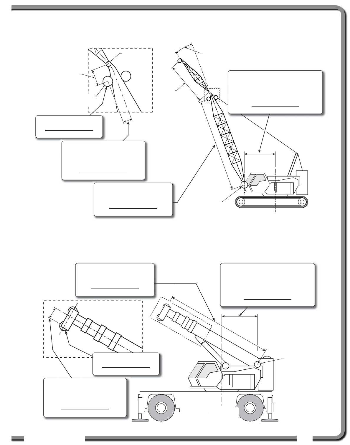
2.6c Basic Radius Parameters for a
Lattice Crane
2.6d Basic Radius Parameters for a
Telescopic Boom Crane
Crane center
of rotation
Boom
base pin
Jib mounting
point
Jib offset
angle
Jib
length
Head
sheave
Sheave head
length parallel
Menu 4C) 12E) SHEAVE HEAD LENGTH
PERPENDICULAR
The distance from the head sheave
centre to the boom centerline.
(Your measurement)
Menu 4C) 1) BOOM LENGTH
The distance from the boom base
pin to the head sheave centre.
(Your measurement)
Menu 4C) 12G) SHEAVE RADIUS
(Your measurement)
Menu 4C) 2) SLEW OFFSET
The distance from the boom base pin to
the crane centre of rotation.
If the boom base pin is behind the centre
of rotation this value will be negative.
(Your measurement)
Boom
base pin
Menu 4C) 12E) SHEAVE HEAD LENGTH
PERPENDICULAR
The distance from the head sheave
centre to the boom centerline.
(Your measurement)
Menu 4C) 1) BOOM LENGTH
The distance from the boom base
pin to the head sheave centre.
(Your measurement)
Menu 4C) 12G) SHEAVE RADIUS
(Your measurement)
Menu 4C) 2) SLEW OFFSET
The distance from the boom base pin to
the crane centre of rotation.
If the boom base pin is behind the centre
of rotation this value will be negative.
(Your measurement)
Crane center
of rotation
Figure: Basic radius parameters for a lattice crane. Typical installation. Not to scale.
Figure: Basic radius parameters for a telescopic boom crane. Typical installation. Not to scale.
20
20 The GS820 System
The GS820 System
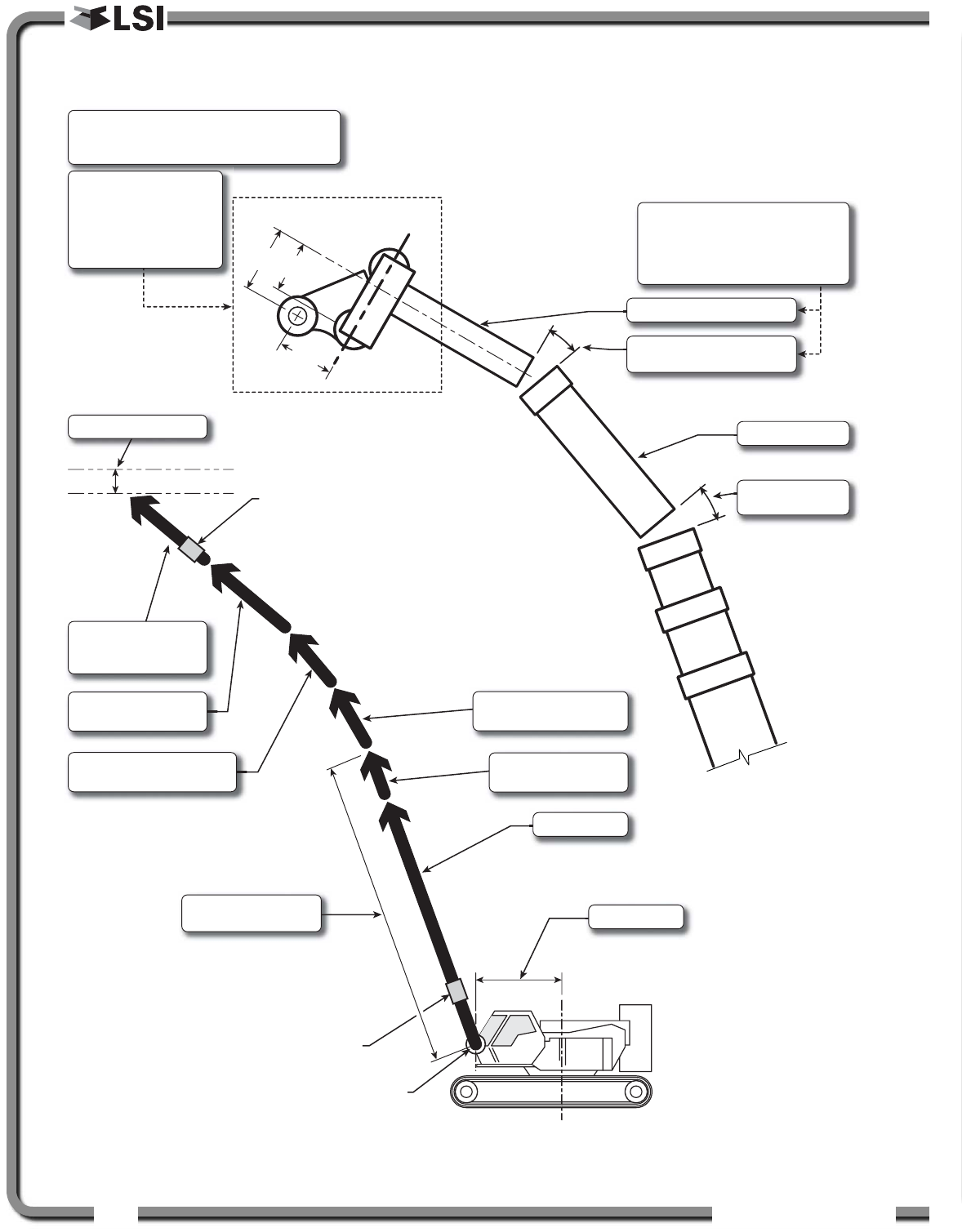
2.6e Advanced Radius Parameters
Crane center
of rotation
Boom
heel pin
Boom
angle sensor
Luffing jib
angle sensor
SLEW OFFSET
BOOM TOP LENGTH
BOOM TOP OFFSET
ANGLE
MAIN BOOM
BOOM TOP LENGTH
& OFFSET ANGLE
FIXED JIB LENGTH
& OFFSET ANGLE
LUFFING JIB LENGTH
(CENTRE SHEAVE TO
CENTRE SHEAVE)
HEIGHT TOLERANCE
LATTICE EXTENSION
LENGTH & OFFSET ANGLE
JIB MOUNTING POINT
PARALLEL & PERPENDICULAR
BOOM LENGTH
includes boom top
LATTICE EXTENSION LENGTH
LATTICE EXTENSION OFFSET
ANGLE
Extensions, two possibilities:
1) MANUAL LENGTH: the offset is
always zero degrees.
2) LATTICE EXTENSION LENGTH: the
offset angle must be adjusted.
Typical sheave heads:
• SHEAVE HEAD LENGTH PERPENDICULAR = D1
• SHEAVE HEAD LENGTH PARALLEL = 0 (typical)
Special top sheaves
(example: rooster):
• SHEAVE HEAD LENGTH
PERPENDICULAR = D2
• SHEAVE HEAD LENGTH
PARALLEL = D3 D2 D1
D3
Figure: Advanced radius parameters. Typical installation. Not to scale.