Load Systems GS200 Wireless Receiver Card Module User Manual GM22x rev20090603 Certification Layout 1
Load Systems International, Inc. Wireless Receiver Card Module GM22x rev20090603 Certification Layout 1
User Manual

GS22X Series
& GS Series Sensors
INSTALLER AND USER’S MANUAL
INSTALLER AND USER’S MANUAL
GM22X REV.20090603 www.loadsystems.com
Manufacturers of Wireless
Weighing Systems
WARNING!
The GS22X series system is designed as an operator aid and is in no
way a substitute for safe operating practice.
!
!
WARNING!
Carefully read and understand this manual before proceeding.
!
!
2
2The GS22X System
The GS22X System
Read and understand the following:
For your safety and that of the people that come
into contact with LSI
LSI products, understand the
significance of the instructions included in this
guide, respect all laws and regulations and comply
with applicable standards.
Pay particular attention to items bearing the alert
symbol and the following words:
Warning: this denotes an instruction that if not
complied with may lead to serious injury or death.
Caution: this denotes an instruction that if not
complied with may lead to product failure or
property damage.
Important: this denotes an instruction that if not
complied with may lead to product performance
issues.
!
!
IMPORTANT!
WARNING!
!
!
!
!
CAUTION!
!
!
BEFORE PROCEEDING
BEFORE PROCEEDING
WARNING!
Installation must be made in
compliance with LSI
LSI instructions and using
LSI
LSI supplied components only. Failure to
install all parts, or replacing parts or
components with parts or components not
supplied by LSI
LSI, may lead to system failure,
serious injury or death.
!
!

ISTALLATIO
ISTALLATIO 3
3
1. INTRODUCTION
1.1 OVERVIEW ........................................5
1.2 START-UP..........................................5
1.3 PRODUCT DESCRIPTION................5
2. CONFIGURATION
2.1 WRCM PC USER INTERFACE AND
DRIVER INSTALLATION ..................6
2.2 APPLICATION OVERVIEW ..............6
2.2a Settings ......................................................6
2.2b Communication Port ..................................6
2.2c Configuration ..............................................6
2.2d Firmware Update ........................................6
2.2e Datalogger Mode ........................................7
2.2f Nodes; sensor type ....................................7
2.3 BASE STATION CONFIGURATION ..7
2.4 NODE CONFIGURATION..................7
2.5 FIRMWARE UPDATE (BASE
STATION ONLY) ................................7
2.5 CONFIGURATION OF A REMOTE RF
NODE ................................................7
3. INSTALLATION
3.1 GS22X INSTALLATION ....................8
3.1a Antenna Position ........................................8
3.1b Power Supply and Lockout Connection ......8
3.1c Wiring..........................................................8
3.2 LOAD CELL ......................................9
3.3 ANGLE SENSORS FOR THE BOOM
OR JIB ............................................10
3.3a Mounting Procedure..................................10
3.3b Angle Calibration Procedure № 1:
Mechanical Set-Up....................................10
3.3c Angle Calibration Procedure № 2: Correct
with the GS22X ........................................11
3.4 ANTI-TWO-BLOCK SWITCH ..........11
3.4a GS050 Installation ....................................11
3.4b GS075 Installation ....................................13
3.4c Chain length adjustment ..........................13
3.5 LENGTH SENSOR CABLE REEL ....14
3.5a Maximum Boom Extension ......................14
3.5b Mounting the Cable Reel ..........................14
3.5c Boom Length Calibration Procedure № 1:
Mechanical Set-Up....................................15
3.5d Boom Length Calibration Procedure № 2:
Correct with the GS22X ............................15
3.7 WIRELESS WIND SPEED SENSOR
GS020 ..............................................19
3.8 WIRELESS LOAD PINS..................20
3.8a LP011, LP015, and LP026 ........................20
3.8b Load Pin Transmitter GS001 ....................20
3.9 LINE RIDING TENSIOMETER ........21
3.9a Line Riding Tensiometer Installation ........21
3.9b Line riding tensiometer installation on a
swing arm..................................................22
3.12 LIST AND TRIM ANGLE SENSOR 26
3.12a Programming the GS22X for List and Trim
Indication26
3.12b Mounting Instructions................................26
3.12c List and Trim Angle Calibration Procedure ..26
3.13 ROPE PAYOUT................................27
3.13a Rope Payout Calibration Procedure № 1:
Mechanical Set-Up....................................27
3.13c Rope Payout Limits ..................................27
3.13d Electrical connections ..............................27
5. MAINTENANCE
5.1 GS22X BASE STATION ..................29
5.1 SENSORS........................................29
5.1a Replacing Sensor Battery ........................29
5.2 ANTI-TWO-BLOCK SWITCH ..........30
5.2a Replacing the GS050 Batteries ................30
5.2b Replacing the GS075 Battery ..................30
5.3 REPLACING A SENSOR ANTENNA ..31
5.4 LOAD CELLS ..................................32
5.4a Reading Accuracy ....................................32
5.4b Load Testing..............................................32
5.4c Care ..........................................................32
7. CERTIFICATION NOTES
TABLE OF CONTENTS
TABLE OF CONTENTS

4
4The GS22X System
The GS22X System
7.1 FCC AND IC – INSTRUCTIONS TO
THE USER ......................................34
8. LSI PRODUCT LIMITED
WARRANTY - 2009/02/16
8.1 LIMITED WARRANTY ....................35
8.2 WARRANTY SERVICES
PROCEDURES................................35
8.3 EXCLUSION OF OTHER
WARRANTIES ................................35
8.4 EXCLUSION ....................................36
8.5 LIMITATION OF LIABILITY ............36
8.6 RECOMMENDED PRACTICES ......36
8.7 CHOICE OF LAW ............................36
8.7a Entire Agreement ......................................36

ISTALLATIO
ISTALLATIO 5
5
1.1
1.1 Overview
Overview
The GS22X series of products are in many ways
similar to a display in that they act as a base station
for LSI’s GS series line of wireless sensors.
However they are not limited to crane applications
but can also be used in a wide range of industrial
process monitoring situations. There is no integrated
display; the system is intended for bridging LSI’s
wireless sensors onto an existing automotive or
industrial automation network. Depending on the
derivative, the GS22X bridges onto a CAN bus or a
RS232. The primary way of configuring sensors into
the system is via a USB cable and end user PC
software.
1.2
1.2 Start-Up
Start-Up
The GS22X series products have been programmed
for the sensors supplied in the shipping box. The
GS22X powers up with its green lights flashing, this
indicates that the receiver is waking up programmed
sensors and creating a radio communication link
with each. Once a reliable radio communication
network is established, the green light will turn off
and flash only when communicating with sensors.
This process may take up to 60 seconds.
1.3
1.3 Product description
Product description
GS220 (Wireless to PC bridge)
• Powered by USB (serial bus emulation), may
have a 2 wire auxillary power cable or
connector.
• USB connector for associating and configuring
sensors as well as setting various system
options using a PC. USB connector also serves
for monitoring wireless sensors from the PC
where it is installed.
GS221 (Wireless to CANBUS bridge)
• 2 Wire Power Cable (some optional lockout
wires may be added on the same cable).
• Standard 3 Pin Deutsch J1939 CANBUS
Connector for interfacing configured sensors to
crane, automotive or inustrial computer
network.
• USB connector for associating and configuring
sensors as well as setting various system options
using a PC or updating firmware with a key.
GS222 (Wireless to RS-232 bridge)
• 2 Wire Power Cable (some optional lockout
wires may be added).
• Standard DB9 serial port connector for
interfacing configured sensors to crane,
automotive or inustrial computer network.
• USB connector for associating and configuring
sensors as well as setting various system
options using a PC.
1. INTRODUCTION
1. INTRODUCTION
WARNING!
The GS22X series system is
designed as an operator aid and is in no way
a substitute for safe operating practice.
!
!
6
6The GS22X System
The GS22X System
The GS22X first configuration should ideally be carried
out before physical installation as it requires a PC with
a USB port. If the GS22X remains fairly accessible, it
can be configured on the spot with a laptop computer.
Refer to Installation section as required.
2.1
2.1 WRCM PC User Interface
WRCM PC User Interface
and Driver Installation
and Driver Installation
1. Install the LSI software
“WRCM PC User
Interface V<version> Setup.exe
”
on a computer
using the cd (or USB key) provided by LSI
LSI.
2. Connect the GS22X to the computer using a
USB port;
a. When connected for the first time or
connected to a new port, Windows will ask to
install the driver. Follow the steps from the
hardware wizard and install the “lsi-
cdcserial_v1.inf” (default location: C:\Program
Files\Load Systems International\WRCM PC
User Interface).
b. In the Connection window, select the WRCM
to connect to and click Ok. If the WRCM
connected is not in the list, click Refresh.
2.2
2.2 Application overview
Application overview
Access the menus from the treeview (in the upper-
left) by double-clicking on it. The appropriated
details will be displayed in the right section of the
application.
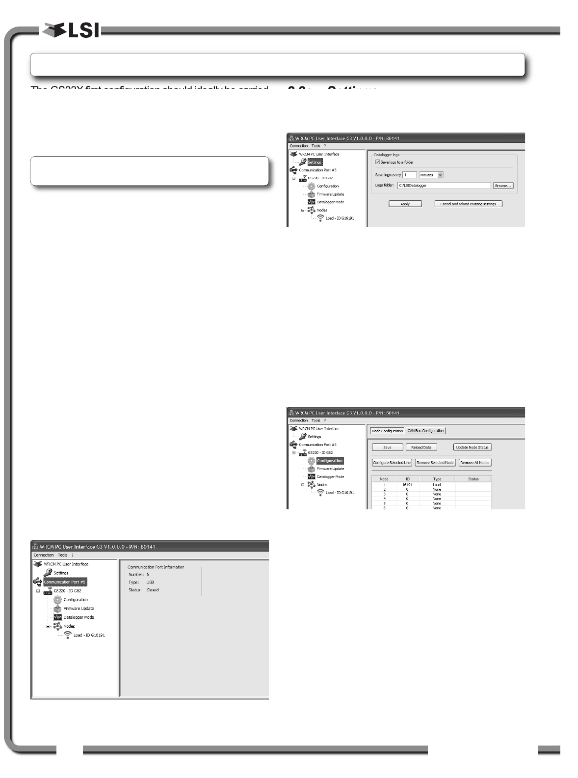
2.2a Settings
The data from the datalogger mode can be saved
on the computer disk.
1. Define the time interval and location folder of
the logs.
2. Press Apply to save changes or Cancel to
reload existing setting.
2.2b Communication Port
Displays the communication port in use, the port
type and status. The Open status indicates that one
of the communication port menus is activated.
2.2c Configuration
Node Configuration:
All sensors in the GS22X system are programmed
in the Configuration list. The information displayed
under Nodes in the treeview section are defined in
Configuration menu. Refer to section 2.4 Node
Configuration to add, remove or modify sensors
information.
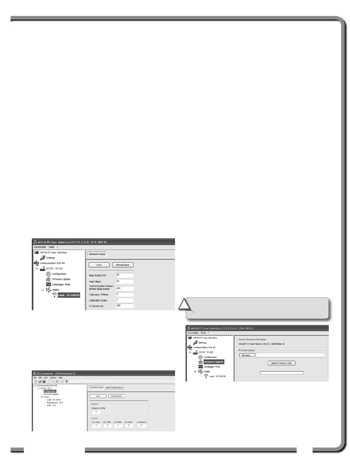
2.2d Firmware Update
Displays the current firmware information and allows
to update the firmware. See 2.5 Firmware Update
section.
2. CONFIGURATION
2. CONFIGURATION
Figure: Application overview.
Figure: Settings
Figure: Node Configuration.
Note: The WRCM software and driver are only
supported by Windows XP.
ISTALLATIO
ISTALLATIO 7
7
2.2e Datalogger Mode
In this mode, live information sent by the wireless
nodes is displayed. The data can be logged to files;
see the Settings section to configure this feature.
2.2f Nodes; sensor type
When a sensor is selected under Nodes, the following
information is communicated to the WRCM;
•Base Station ID: Number engraved on the sensor.
•Heart Beat: When no change is detected in sensor
value, the sensor status will be communicated to
the GS22X in the interval (in seconds) indicated.
•Communication timeout before sleep mode:
When the base station stops communicating
information to the sensors, the sensors become
innactive (sleep mode). The value indicated is
the time (in seconds) before the sensors switch
to the sleep mode.
•Calibration Offset: Allows to offset the value
configured from the firmware.
• Calibration Scale: Allows to scale the value
configured from the firmware.
•Tx Sensivity: Adjust sensors sensivity to value
change.
2.3
2.3 Base Station Configuration
Base Station Configuration
There is no allowance to set device ID,
manufacturing step, etc., which is not available.
Contact your LSI
LSI representative or LSI
LSI technical
support representative as required.
2.4
2.4 Node Configuration
Node Configuration
1. In the Configuration menu, select Node
Configuration.
2. Adding nodes: To add sensors in the node list;
Right-click on Nodes in the treeview section to
add a sensor to the list using the scroll-box or;
In the Configuration menu, select a line and
click on Configure selected line or double-click
on the line to modify.
Enter the sensor ID and the node RF type.
3. Removing nodes: To remove any sensor from
the list;
Right-click on the sensor under Nodes in the
treeview section and select Delete or;
In the Configuration menu, select the sensor
line to remove and click on Remove selected
node.
4. Reload Data: Reload data from the WRCM and
display data without saving any changes.
5. Save: Save changes in the WRCM memory. Save
is automaticly followed by Update node status.
2.5
2.5 Firmware Update (Base
Firmware Update (Base
station only)
station only)
1. Select Firmware Update in the treeview
section.
2. In the right section, click on Browse to select
the update file (extension .220) and then hit
Update Firmware Now.
Figure: GS22X base station configuration.
Figure: Firmware update.
IMPORTANT!
The updated firmware will
overwrite the current configuration settings.
!
!
Figure: Nodes standard setup.
8
8The GS22X System
The GS22X System
3.1
3.1 GS22X Installation
GS22X Installation
It is recommended to install the receiver on the right
side or left side of the cab, usually on the same side
as the wind speed sensor. The best positioning
would ensure line of sight in most boom position. If
line of sight is not always possible, position
optimisation could help improve the radio link, which
improves battery life. If possible, do not hide the
receiver behind metal structure.
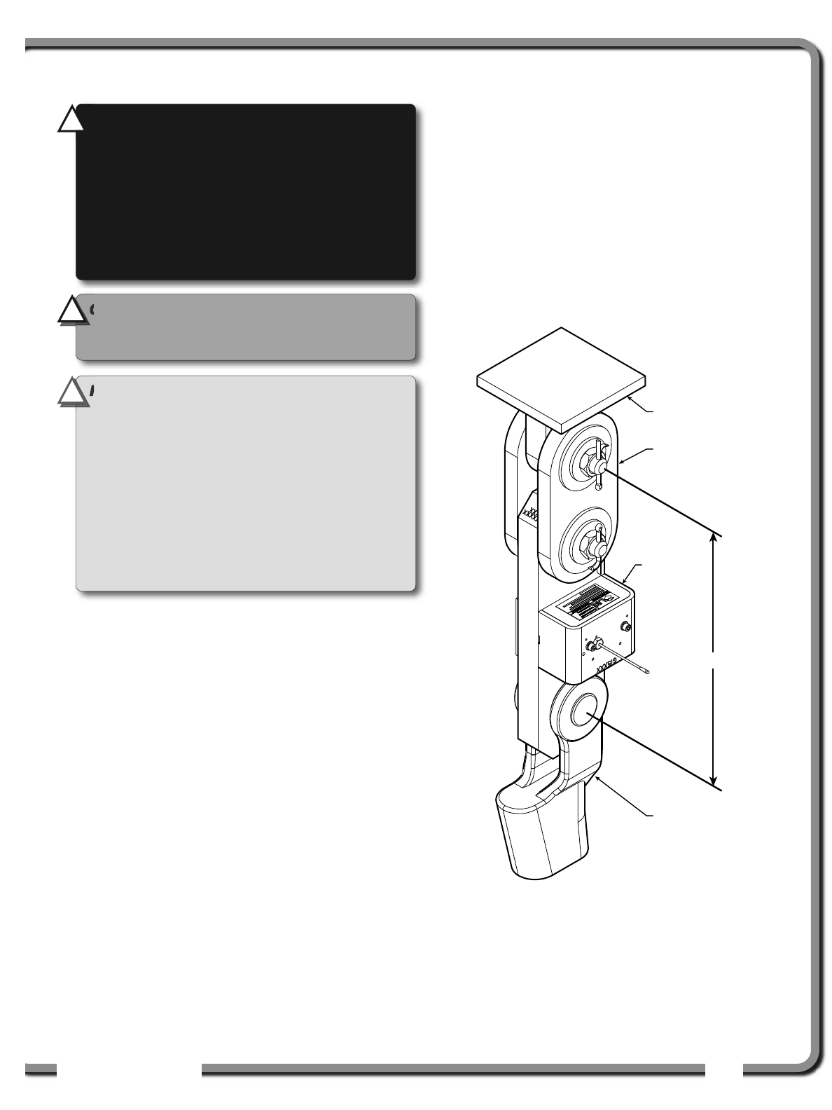
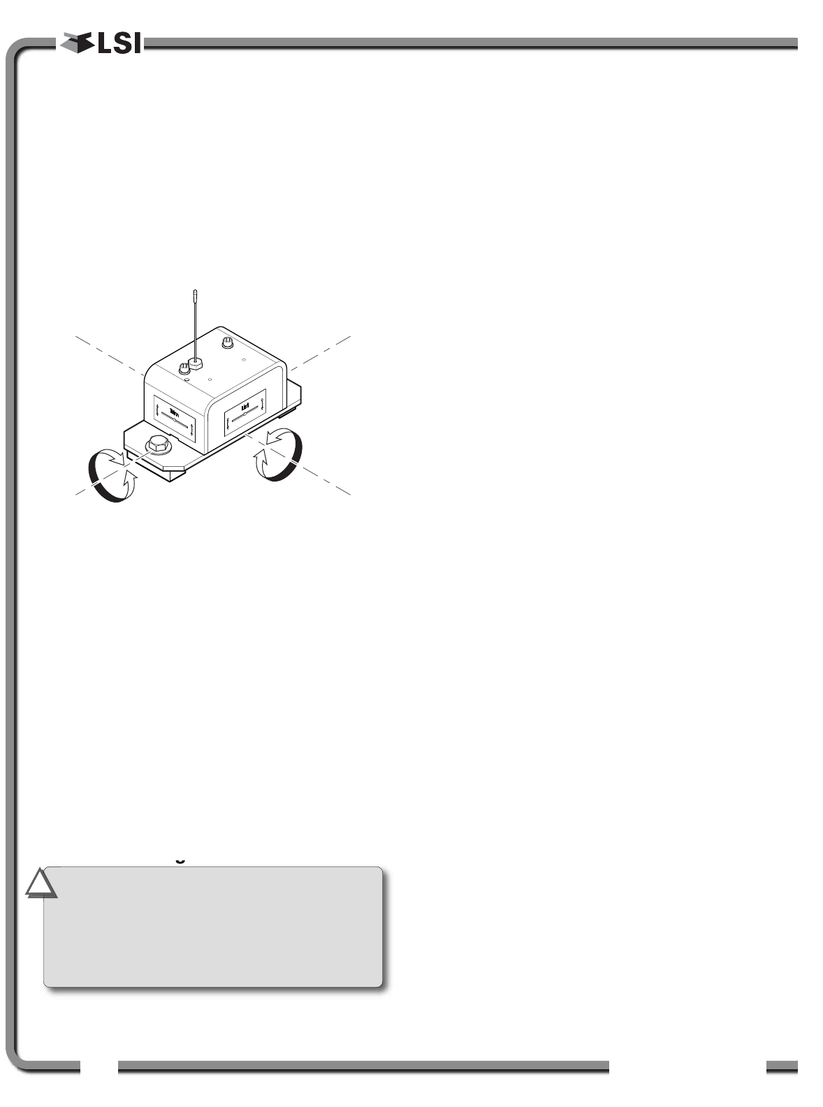
3.1a Antenna Position
For optimal performance the antenna should be
positioned on its side such that it is parallel to
the sensor antennas (but not pointing directly to or
directly away from them).
1. Adjust the antenna position with the articulating base.
2. The antenna should have 5 inches of clear
space all around it.
3. The antenna should have an unobstructed line of
sight to all sensor antennas at all boom angles.
3.1b Power Supply and Lockout
Connection
3.1c Wiring
Table: Wire description
Wire Color Description
Red . . . . . . . . . . . . Power supply, 9 to 36 volts
Black . . . . . . . . . . . . . . . . . . . . . . . . . . Ground
Blue . . . . . . . . . . . . . . . . . . . . CAN bus ground
. . . . . . . . . . . . (not required on most CAN bus)
Green . . . . . . . . . . . . . . . . . . . . . . . . . . CAN-H
White . . . . . . . . . . . . . . . . . . . . . . . . . . . CAN-L
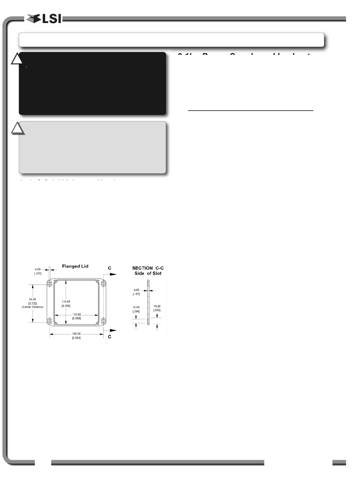
IMPORTANT!
Do not power wash the
GS22X. The GS22X is not designed to
withstand high-pressure washing devices that
can erode the membrane fascia seal or create
fissures in the membrane fascia. Power washing
the display voids warranty coverage.
!
!
WARNING!
Installation must be made in
compliance with LSI
LSI instructions and using
LSI
LSI supplied components only. Failure to
install all parts, or replacing parts or
components with parts or components not
supplied by LSI
LSI, may lead to system failure,
serious injury or death.
!
!
3.
3. INSTALLATION
INSTALLATION
Figure: GS22X dimensions. Not to scale.
ISTALLATIO
ISTALLATIO 9
9
3.2
3.2 Load Cell
Load Cell
1. Install load cell bushings as supplied by LSI
LSI.
Assembly of the load cell and adapter plates
must be configured to the pin size required by
the specific dead end or hook to which it is to be
attached. In all cases, the bushings supplied by
LSI
LSI must be used where possible to adapt the
holes in the load cell to the pins. Bushings must
be secured with the two allen screws provided,
one on each side of the load cell.
2. As required, place a washer between adapter
plate and pin head or nut on each end of the pin
that links the adapter plates to the load cell.
Additional washers should be added equally to
each end of the pin as required to inhibit
excessive lateral movement of load cell
(maximum 1/8” total movement) and adapter
plates along the pin.
3. If the dead end or hook to be connected to the
adapter plates requires a larger opening,
washers may be placed between the load cell
and the adapter plates equally on both sides of
the load cell.
4. In all cases the washers must be placed
symmetrically such that the load cell is centered
on the pins to avoid uneven loading.
5. Secure the pins with the nuts and cotter pins
provided.
6. A qualified (lift supervisor or crane inspector)
person must verify every lift assembly before
first use and periodically thereafter (one to
twelve months), including before any new,
difficult or otherwise different lift.
Crane dead
end
Plate kit for
loadlink
Loadcell
Wedge socket
to loaded cable
C/C
Figure: Typical load cell and adapter plate assembly installed.
IMPORTANT!
The load cell antenna should
not be in contact with metal.
IMPORTANT!
For optimal performance and
signal reception, the load cell antenna should
have a clear line of sight to the GS22X base
station.
IMPORTANT!
The load cell antenna should
point to the left or to the right of the boom; it
should not point directly to, or away from, the
GS22X base station.
WARNING!
Capacity and safety factor for
load cells and adapter plate assemblies are
calculated for loads along the intended axis
of load (vertical with the assembly hanging
free); side loading may cause load cell and
adapter plate assembly to fail, causing load to
drop. Lifts must be rigged such that the load
cell and adapter plate assembly hang free and
not be subjected to side loading.
!
!
!
!
CAUTION!
The load cell must be centered
on the pins to avoid uneven loading on the
plate kit assembly.
!
!
10
10 The GS22X System
The GS22X System
3.3
3.3 Angle Sensors for the
Angle Sensors for the
Boom or Jib
Boom or Jib
3.3a Mounting Procedure
The GS010 series angle sensors can be turned on
by starting up the GS22X base station to which they
are programmed. The angle sensor can then assist
in levelling itself with the red and green LED.
1. Determine the angle sensor position.
a. The GS010-01 boom angle sensor can
be mounted on either side of the boom.
b. The GS010-02 360° angle sensor must
be mounted on the port side of the jib.
c. The angle sensor must be level with the
boom or jib centerline.
d. The top / bottom axis of the angle sensor
must be within 15 degrees of vertical
e. The angle sensor should have a clear line
of sight to the cabin mounted display.
f. The angle sensor antenna should not
contact a metal object.
2. Install the welding pads; keep the angle sensor
at least three feet from the weld site and any
connecting metal objects while welding.
3. Mount the angle sensor to the weld pads with
the screws and washers provided.
4. Verify the angle indication; the GS22X must be
connected to a computer.
5. If the angle displayed by a GS010-01 boom
angle sensor is a high negative value, then tilt
the angle sensor up over 45 degrees, and then
tilt back down to horizontal. The GS010-01
boom angle sensor will automatically detect on
which side of the boom it is installed and correct
angle indication accordingly.
3.3b Angle Calibration Procedure
№ 1: Mechanical Set-Up
The GS22X must be connected to a computer to
proceed with calibration procedure.
1. Level the boom such that it is perfectly
horizontal; use a high quality bubble or digital
angle sensor. If the GS22X base station
indicates 0.0 degrees then angle calibration is
complete; if not then continue to step 2.
2. For GS011 angle/length sensors only: Carefully
remove the cover of the GS101 cable reel.
3. Loosen the mounting screw in the slotted hole
of the angle sensor mounting plate.
Cabin
Boom
Angle Sensor
Boom
C
L
Boom
Angle Sensor
Cabin
Boom
Angle Sensor
Cabin
Wedge
Figure: Angle sensor level with the boom (typical installation) -
Side View
Figure: Angle sensor top/bottom axis within 15° of vertical
(typical installation) - Front View
Figure: Wedge used to mount the angle sensor with its
top/bottom axis within 15° of vertical (typical
installation) - Front View
Note: Press Update Node Status in the WRCM PC
user interface to display the current angle value.
IMPORTANT!
Keep the angle sensor away
from the boom and any connecting metal
structures when welding the metal lugs to the
boom. Proximity to welding may cause
permanent damage to the angle sensor and
prevent accurate angle indication.
!
!
WARNING!
The angle reading may be
affected by vibration and may fluctuate; the
angle sensor should not be installed in close
proximity to a high RPM electric motor or other
source of high frequency vibration.
!
!
WARNING!
Failure to ensure the boom is
levelled will result in false reading of the
crane’s radius hence the risk of structural
failure of the crane or crane tipping over.
!
!

ISTALLATIO
ISTALLATIO 11
11
4. Pivot the angle sensor slightly until angle
indication is correct. Repeat the angle validation
(step 1) as required.
3.3c Angle Calibration Procedure
№ 2: Correct with the GS22X
The GS22X must be connected to a computer to
proceed with calibration procedure.
Calibrate angle indication by adjusting the trim
(offset) value in the WRCM PC user interface; the
GS22X will then communicate the updated trim
value to the sensor.
1. Position the boom at a precisely known angle.
2. Adjust the trim value in the WRCM.
Example: If angle indicated is 0.3° over the actual
angle, adjust the trim value to -0.3.
Example: If angle indicated is 0.9° below the actual
angle, adjust the trim value to 0.9.
3. Verify accurate angle indication at both very
high and very low angles.
3.4
3.4 Anti-Two-Block Switch
Anti-Two-Block Switch
Verify the anti-two-block switch is programmed to
the GS22X base station. Switches shipped with
GS22X are pre-programmed in the factory. Test: if
the switch has been programmed to the display
then the display will go in to two-block alarm when
the wire rope of the switch is released. If the switch
has not been programmed to the GS22X, this
should be done before proceeding with installation.
See the section 2.4 Nodes Configuration.
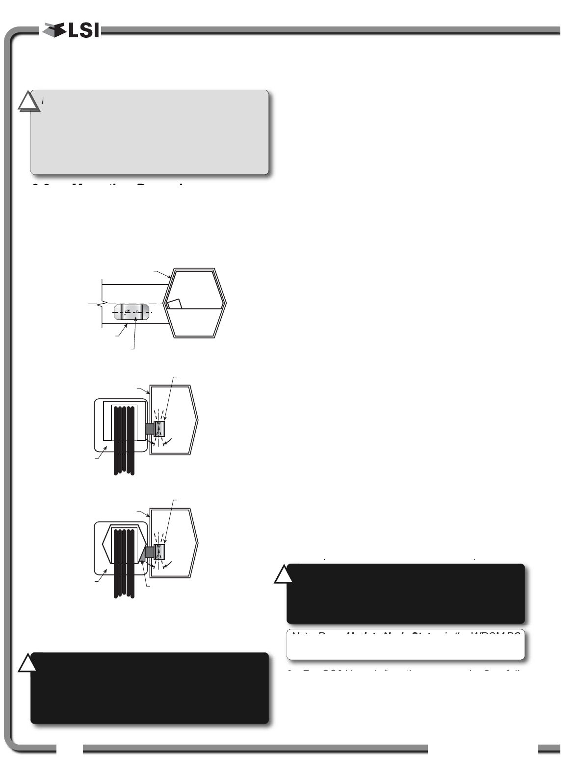
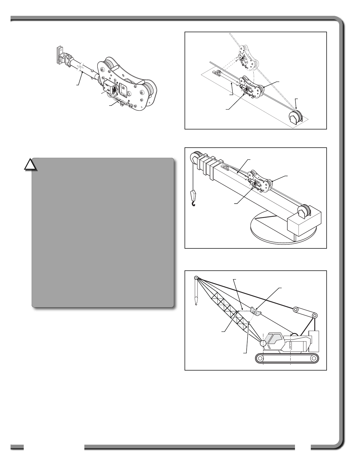
3.4a GS050 Installation
1. Position the sensor mounting bracket. To
ensure that the sensor can pivot securely on the
mounting bracket throughout the full range of
boom angle, the mounting bracket must be
positioned at a 30° from horizontal with the
boom parallel to the ground and such that the
locking pin of the mounting bracket points up.
Bolt or weld securely.
WARNING!
Keep the anti-two-block switch
away from the boom and any connecting
metal structures when welding mounting
brackets to the boom. Proximity to welding
may cause permanent damage to the anti-
two-block switch and render the anti-two-
block system unsafe.
!
!
IMPORTANT!
To ensure reliable radio
communication between the anti-two-block
switch and the GS22X base station the
following conditions must be respected:
• The antenna of the anti-two-block switch
should not be in contact with metal.
• The anti-two-block switch antenna should
point to the left or to the right of the boom;
it should not point directly to, or away from,
the GS22X base station.
• The anti-two-block switch antenna should
have a clear line of sight to the GS22X base
station; in most cases this means mounting
the sensor on the same side of the boom as
the operator's cab.
!
!
12
12 The GS22X System
The GS22X System
If the head sheave diameter is between 8 and 16
inches (20-41 centimetres) then two mounting
brackets will be required to permit both live and dead
end mounting.
For live end mounting on multiple sheave blocks
with sheaves greater than 16 inches (41
centimetres) in diameter consult your service
representative.
For fast line weight installation place the anti-two-
block switch mounting bracket directly below the
sheave center as low and as close to the edge of
the sheave as possible. Place the fast line weight
mounting bracket on the opposite side of the
sheave with the chain hole pointing down and lined
up opposite the pivot of the anti-two-block switch
mounting bracket.
2. Mount the GS050 on the bracket and verify that
the GS050 can rotate freely through all possible
boom movements without being able to come
off the bracket.
3. Install the weight and chain assembly around
the cable and attach the other end of the chain
to the GS050. Tighten all the chain links of the
chain assembly.
4. Adjust chain length as required, see sub-section
Chain length adjustment.
5. Test system function.
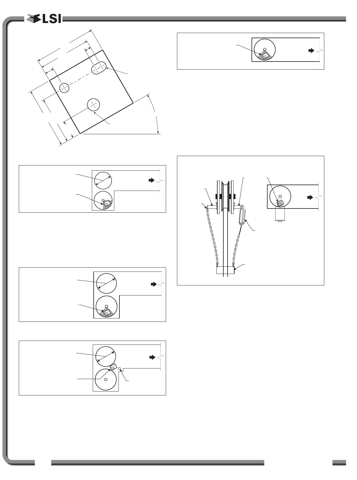
ø0.38
Pivot Center
(Anchor shaft)
30°
2.50
2.125
0.375 0.25
2.5
1.9375
0.75
Up to 8 in. (20 cm)
diameter Boom
base
Mount bracket below
and behind sheave
center.
Figure: Anti-two-block switch placement on a telescopic boom
8-16 in. (20-41 cm)
diameter Boom
base
Mount bracket 4 in.
(10 cm) below sheave
center.
Figure: Anti-two-block switch placement for live end mounting
on a lattice boom
8-16 in. (20-41 cm)
diameter Boom
base
Dead
end pin
Mount bracket 4 in.
(10 cm) in front of the
dead end pin.
Figure: Anti-two-block switch placement for dead end
mounting on a lattice boom
Boom
base
Mount bracket 4 in.
(10 cm) below sheave
center.
Figure: Jib, rooster or other extension; anti-two-block switch
placement for single part of line operation only
Boom
base
Mount bracket directly
below sheave
center as low as
possible.
Fast line
mounting
bracket
Fast line
weight
Anti-two-block
switch GS050
Front View
Chain
hole
Figure: Fast line weight installation
Figure: Bracket footprint and orientation,
All dimensions are in inches. Not to scale.
ISTALLATIO
ISTALLATIO 13
13
3.4b GS075 Installation
1. Optional Bracket: Position the optional mounting
bracket on the boom. Bolt or weld securely.
2. Attach one end of the chain assembly to the
optional bracket or to the boom and the other
end to the eye bolt of the GS075. Tighten all the
chain links of the chain assembly.
3. Remove the hair pin and the clevis pin and
open the back end of the GS075. Install the
GS075 around the cable and then put the clevis
pin back in.
4. Adjust chain length as required, see sub-section
Chain length adjustment.
5. Test system function.
3.4c Chain length adjustment
1. Chain length adjustment № 1 – minimum boom
angle
a. At minimum boom angle, with no
additional weight on the hook block and
one part of line only, lift the boom just
enough to have the hook block suspend
and clear the sensor chain and weight.
b. Hoist slowly until the buzzer sounds. Note
the hoisting distance remaining; this
distance must be great enough to allow
the operator and the lockout system, if
installed, to prevent a two-block event. If
necessary, add chain between the sensor
and weight to increase warning distance.
If still insufficient, contact your service
representative.
2. Chain length adjustment № 2 – maximum boom
angle
a. Raise the boom to the maximum angle.
b. Hoist slowly as described in Step 1.b. Verify
that the warning distance is equal to or
greater than that determined at the
minimum boom angle.
3. Chain length adjustment № 3 – speed test:
Lower the boom until the weight height becomes
visually clear to the operator. Repeatedly create
two-block, progressively hoisting faster, to
ensure that the warning and lockout work within
acceptable amount of time and distance.
Increase the length of the chain if needed.
B) Hook block stops
rising, two-block
prevented with
safety margin
Boom
base
A) Anti-two-block
switch triggers
two-block alarm
Boom
base
Figure: Chain length test at minimum angle
B) Hook block stop
s
rising, two-block
prevented with
safety margin
Boom
base
A) Anti-two-block
switch triggers
two-block alarm
Boom
base
Figure: Chain length test at maximum angle
GS075
Increase Increase
GS050
weight
Figure: Chain length adjustment
Eye bolt
Clevis pin
Figure: Install the GS075 around the cable
IMPORTANT!
GS050: to increase chain length, only use
lightweight chain.
!
!
14
14 The GS22X System
The GS22X System
3.5
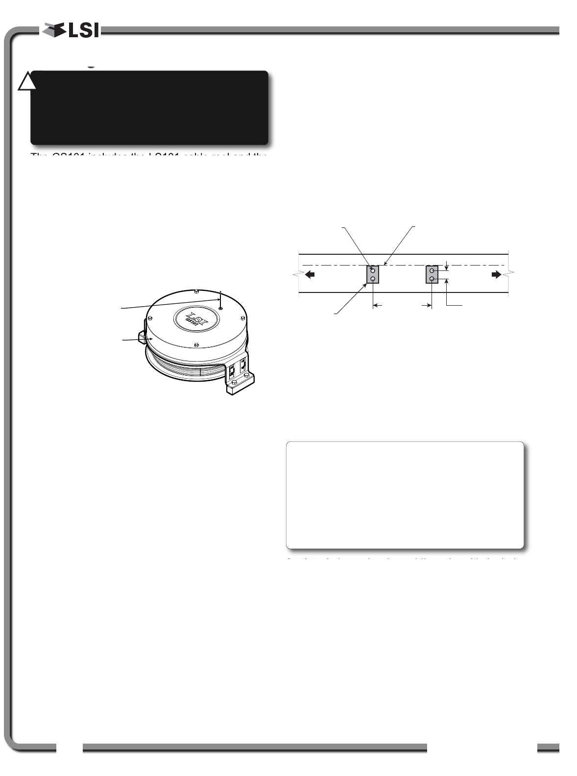
3.5 Length Sensor Cable Reel
Length Sensor Cable Reel
The GS101 includes the LS101 cable reel and the
GS011 angle/length sensor. The GS011 is
concealed under the cover of the LS101, though
the antenna is visible. Following cable reel
installation and boom length indication calibration,
boom angle indication will have to be verified and
possibly calibrated. Refer to Angle Calibration
Procedure № 1: Mechanical Set-Up and Angle
Calibration Procedure № 2: Correct with the
GS22X, sections of this manual.
3.5a Maximum Boom Extension
Confirm the maximum extension of the LS101 cable
reel is compatible with the maximum boom length.
Step 1. Note the cable reel maximum extension: 100 feet
(30.5 metres) unless specified otherwise.
T = ____________________
Step 2. Note the retracted boom length.
A = ____________________
Step 3. Note the maximum extended boom length, not
including jib.
B = ____________________
Step 4. Calculate maximum boom extension.
C = B – A =____________________
Step 5. Compare cable reel maximum extension (T) to
maximum boom extension (C).
D = T – C =____________________
Maximum cable reel extension must be greater
than maximum boom extension.
3.5b Mounting the Cable Reel
1. Determine placement. Find a clear mounting
position on the left side of the first (main)
section of the boom. The mounting position
should be close to the base of the boom; at
least ten feet (three metres) from the tip of the
first section and where the cable reel won’t
obstruct free boom movement at all boom
angles and slew positions. Furthermore, the
reel must be placed such that the cable has a
clear straight line to the end of the last section
at all boom lengths.
2. Mount the welding tabs. They must be placed
parallel to each other, with 16 1/8” inches
between the holes’ centres. Install the tabs such
that they create a level mounting position in line
with the boom at 0 degrees.
3. Attach the reel to the welding tabs with the bolts
provided.
4. Install the first cable guide (PA111) about 10 feet (3
metres) from the cable reel. Correct alignment of
the first guide is critical to ensure orderly winding
of the cable on the reel. Install the other guides at
the end of each of the intermediate sections and
the anchor (PA113) at the end of the last section.
All guides must be aligned so as to permit
unobstructed movement of the cable.
5. Pull out at least 5 feet (1-1/2 metres) of cable,
but not more than half the excess extension of
GS011 angle/length
sensor antenna
LS011 length sensor
cable reel
Figure: GS101 angle & length sensor
Boom
base
Boom
tip
Welding
pads holes
16 1/8 in. apart,
centre-to-centre
Welding
pad holes
2 1/4 in. apart,
centre-to-centre
Welding
pads
Welding
pad holes
tapped 3/8-16
Welding pads level and
in line with the boom at
0 degrees from horizontal
Figure: Cable reel mounting position
WARNING!
Arc welding may damage LSI
LSI
sensors, causing immediate failure or greatly
reducing functional life. Arc welding on or near
LSI
LSI equipment will void warranty. Keep LSI
LSI
equipment well clear of any arc welding.
!
!
Note: When factory installed, the GS011
angle/length sensor transmitter is integrated to the
LS101 cable reel with the angle sensor zeroed. If
the cable reel is installed perfectly level on the
boom at 0 degrees, the angle sensor of the GS011
will also be zeroed. Minor adjustments to the angle
sensor (within plus or minus two degrees) are
possible after cable reel installation.
ISTALLATIO
ISTALLATIO 15
15
measurement D. Feed through the cable guides
and attach to the cable anchor on the tip of the
last boom section. If additional cable length is
required to reach the cable anchor point
remove winds from the reel without putting
additional tension on the cable reel spring.
There should be minimal tension on the cable
reel spring when the boom is fully retracted.
The GS22X must be connected to a computer to
proceed with the following.
6. Verify the boom length indicated by the WRCM
PC user interface. Boom length indicated
should equal the actual total boom length. The
actual boom length is the distance from the
boom base pin to the head sheave centre as
measured along the boom centreline.
Depending on the exact placement of the cable
reel and the cable anchor the displayed length
may differ from the actual length.
3.5c Boom Length Calibration
Procedure № 1: Mechanical
Set-Up
The GS22X must be connected to a computer to
proceed with calibration procedure.
1. Fully retract the boom
2. Adjust the loose wire rope at the boom tip so
that the displayed boom length matches the
actual boom length.
3. Fully extend the boom
4. Verify the boom length indicated at full boom
extension matches the actual fully extended
boom length. If not then follow Boom Length
Calibration Procedure № 2: Correct with the
GS22X.
3.5d Boom Length Calibration
Procedure № 2: Correct with
the GS22X
The GS22X must be connected to a computer to
proceed with calibration procedure.
If the displayed boom length does not match the
actual length of the boom retracted or extended and
if it is not possible to easily correct by following 2.6c
Boom Length Calibration Procedure № 1, then
follow this procedure. This procedure is completed in
the operators cab, it requires fully retracting, and
then fully extending the boom, as prompted by the
on screen instructions.
1. Select the length sensor in the Nodes list in the
WRCM PC user interface.
2. Press Next to start the wizard.
6. Note the units that will be used during the
calibration wizard, and then press Next.
7. Fully retract the boom, and then press Next.
8. Use Up and Down to adjust the length value
displayed to equal the actual fully retracted
boom length, and then press Next.
9. Fully extend the boom, and then press Next.
10.Use Up and Down to adjust the length value
displayed to equal the actual fully extended
boom length, and then press Next.
11. Note the new trim value, and then press Next.
12.Note the new scale value, and then press Next.
13.Press Enter to send the new calibration to the
length sensor.
14.Press Exit three times to return to the operation
display.
Cable
anchor
Cable guide
Cable
reel
Boom length
Boom
base
pin
Figure: The actual boom length. typical installation.
CAUTION!
Visually monitor remaining
length on the cable reel as the boom is
extended for the first time following
installation. This generally requires a second
person (in addition to the operator).
!
!
ISTALLATIO
ISTALLATIO 19
19
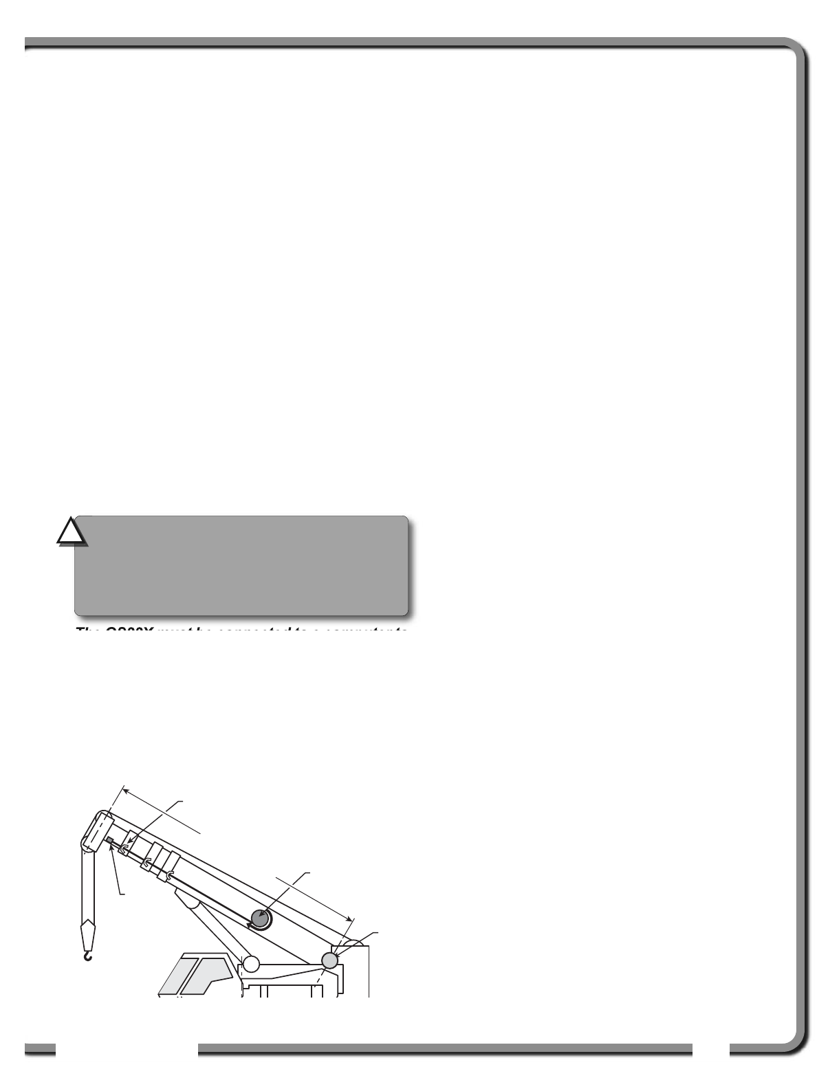
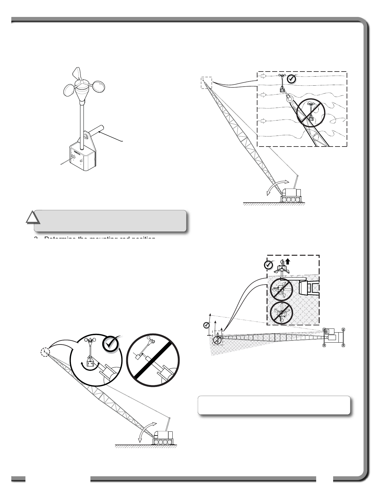
3.7
3.7 Wireless Wind Speed
Wireless Wind Speed
Sensor GS020
Sensor GS020
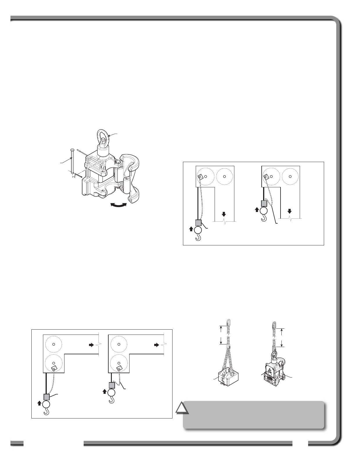
1. Remove the mounting rod from the wind speed
sensor.
2. Determine the mounting rod position.
a. Install the mounting rod on the same side
of the boom as the cabin mounted
display, perpendicular to the boom, and
at the highest point possible.
b. The wind speed sensor must pivot freely
on the mounting rod at all boom angles.
c. The wind cups must be fully exposed to
the wind and spin freely at all boom
angles.
d. There should be a clear and unobstructed
line of sight between the wind speed
sensor antenna and the cabin mounted
display unit.
e. The transmitter antenna should not
contact any metal object.
3. Weld or screw the mounting rod to the boom at
the selected position.
4. Re-position the wind speed sensor on the
mounting rod, add the washer and secure with
the cotter pin.
Mounting rod
Figure: GS020 wireless wind speed sensor
Figure: Swivel orientation
Figure: Wind clearance
Figure: Radio line of sight - Crane top view
IMPORTANT!
Do not weld in proximity to
LSI
LSI sensor/transmitters.
!
!
Note: Angle iron can be used to extend the
mounting position to be clear of the boom top.
20
20 The GS22X System
The GS22X System
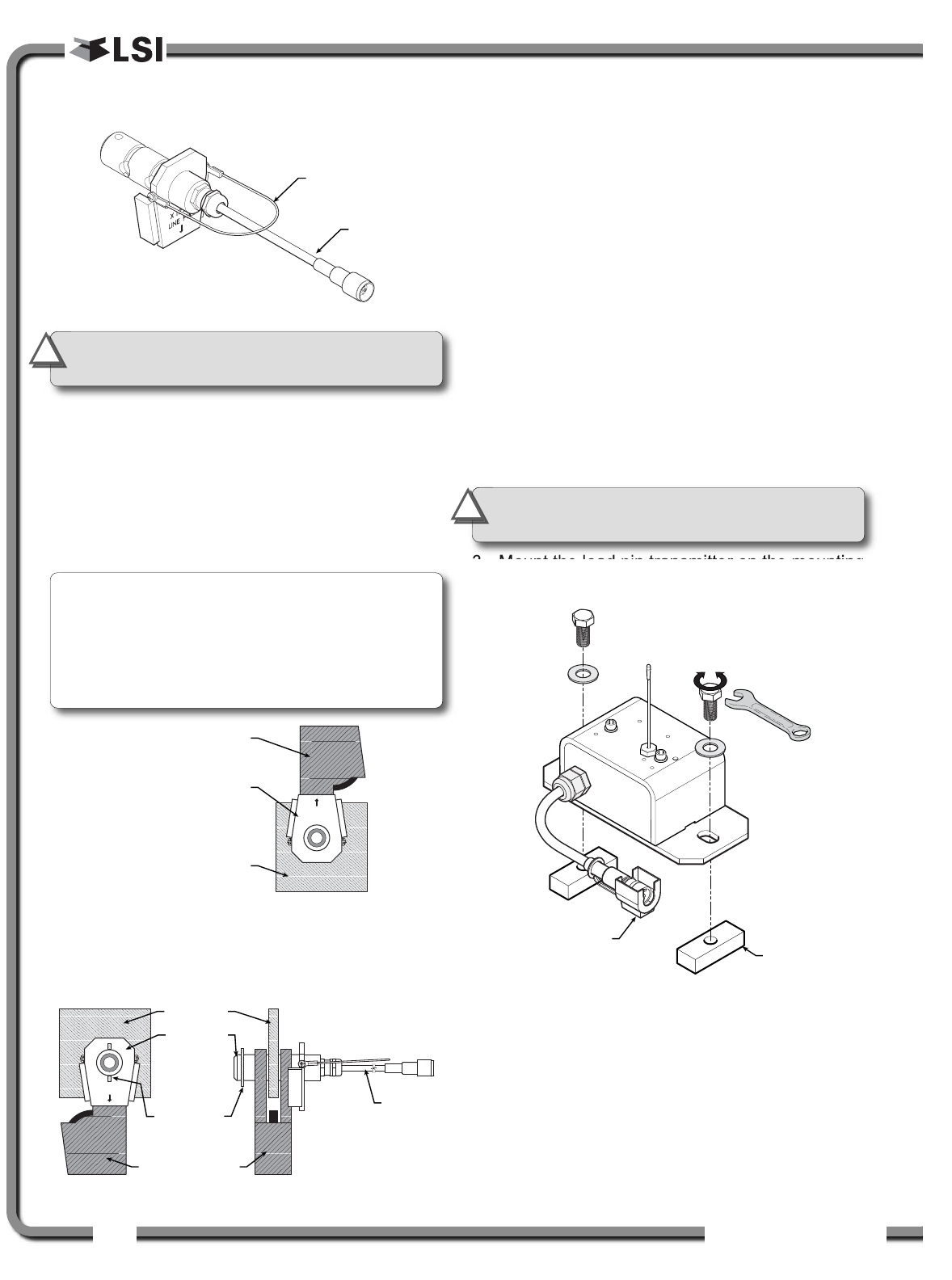
3.8
3.8 Wireless Load Pins
Wireless Load Pins
3.8a LP011, LP015, and LP026
1. Mount the load pin to the boom tip or block by
replacing the pin of the wedge socket. The load
pin is directional and must be oriented correctly
to indicate load accurately. Install the pin so that
the bracket embraces the wedge socket and
prevents pin rotation.
2. Secure the load pin in place with a cotter pin or
other suitable keeper device.
3.8b Load Pin Transmitter GS001
1. Determine the transmitter mounting position.
a. The load pin and transmitter pigtails must
connect easily without stretching or
kinking at all boom angles and working
conditions. The jumper cable may be
used between the load pin and
transmitter to increase transmitter
placement options.
b. There must be direct unobstructed line of
sight from the transmitter to the display;
this may not be required on cranes with a
maximum boom length less than 100 feet
(33 metres).
c. The transmitter antenna must not be in
contact with any metal object.
2. Weld the mounting blocks where required.
3. Mount the load pin transmitter on the mounting
blocks.
Pigtail
Handle wire
Figure: Load pin
AA10K11
LINE PULL
Wedge socket
Load pin
Hook ball or block
Figure: Load pin LP011, LP015 or LP026 -
Installation on a single part block
AA10K11
LINE PULL
Wedge socket
Load pin
Cotter pin Pigtail
Boom tip
Figure: Load pin LP011, LP015 or LP026 - Installation at boom tip
Connect the
transmitter pigtail
to the Load pin
pigtail
Mounting
block
Figure: Install the load pin transmitter GS001
IMPORTANT!
Do not pull on a load pin
by the pigtail, pull on the handle wire.
!
!
IMPORTANT!
Do not weld in proximity to
LSI
LSI sensor/transmitters.
!
!
Note: When installed at the boom tip the lot
number can be read right side up and the “line
pull” arrow points down towards the block. When
installed at the hook ball or block, the lot number
can be read upside down and the “line pull” arrow
points up towards the boom tip.
ISTALLATIO
ISTALLATIO 21
21
3.9
3.9 Line Riding Tensiometer
Line Riding Tensiometer
3.9a Line Riding Tensiometer
Installation
Swing arm mounted
Application:
Most applications, mounted as far up the
boom base as practical with the swing
arm base attached near the tip of the butt
section. This mounting allows the line
riding tensiometer to follow the movement
of the wire rope path.
Commentary:
Make sure that the swing arm is long
enough to allow free movement at any
boom angle.
Swing Arm
Line Riding
Tensiometer
Figure: Line riding tensiometer
Line Riding
Tensiometer
Swing Arm
Bracket and
Landing Pad
(wooden cushion)
Mounting
Bracket
(for swing arm)
Figure: Example of a typical installation on a lattice boom
crane, allows for lower clearance (not to scale)
CAUTION!
The Line Riding tensiometer must be held by the
swing arm and the tension of the wire rope; do
not fix the line riding tensiometer to the boom.
The Ratio of the distance between the line
riding tensiometer and the hoist drum must
be 18:1 as minimum to allow a normal
winding on the drum.
The angle between the swing arm and the
measured rope shouldn’t exceed 30 degrees.
Two Landing Pads (Wooden cushion) must be
added to allow line riding tensiometer sitting
when the boom is down.
Nothing should limit free displacement of
the swing arm & line riding tensiometer
assembly at any boom angle or configuration.
!
!
Swing Arm
Line Riding
Tensiometer
Landing
Pads
Figure: Example of a typical installation on a telescopic boom
crane (not to scale)
Swing Arm
Line Riding
Tensiometer
Hoist
drum
Landing
Pads
Figure: Typical installation (not to scale)
22
22 The GS22X System
The GS22X System
3.9b Line riding tensiometer
installation on a swing arm
1. Verify that the line riding tensiometer size fits
with the wire rope diameter.
Table: Line riding tensiometer part number and rope diamater.
2. Identify the hoist rope and choose a proper
place, normally as far up the butt section as
practical, to install the swing arm.
3. Install the swing arm by welding, bolting or
strapping it to the boom. It should be located to
be as centered as possible with the boom end
sheave and positioned such that neither the
swing arm nor the line riding tensiometer
interfere with the hoist rope or other objects.
4. Remove top sheaves and top bolts & spacers
from the line riding tensiometer*. Place the line
riding tensiometer on the unloaded hoist rope,
oriented such that the transmitter antenna is on
the cab side and the swing arm holes are
directed to the boom top. Re-install bolts and
sheaves.
5. Attach the swing arm end to the line riding
tensiometer.
6. Verify that the angle the swing arm forms with
the boom is not too large and that nothing limits
free displacement of the swing arm and line
riding tensiometer assembly at any boom angle
or configuration. Extend the swing arm as
needed.
7. If the line riding tensiometer has been supplied
with rope payout, ensure that both proximity
switches (led) operate as the appropriate
sheave turns.
8. Verify that the sensor antenna is not curved.
9. Verify that all bolts are tight.
10.Operate the hoist to verify correct line riding
tensiometer function.
11. Proceed to load pin / Line riding tensiometer
calibration of the display/receiver (see Line
Riding tensiometer Calibration section).
* The hoist rope can also be installed by passing
the wire rope around the pulleys when the hook
does not interfere.
Pulley
Figure: Removing top sheaves, bolts and spacers on Line
Riding tensiometer type 1 (LD008 shown).
Pulley
Figure: Removing top sheaves, bolts and spacers on Line
Riding tensiometer type 2 (LD024 shown).
Frame
Sheave
Size
P/N
GS series
line-rider with
swign-arm and
transmitter P/N
Cable
size
Inches
(mm)
Small (4.25") LD006 GD004-0375 3/8"
Small (4.25") LD006 GD004-0500 1/2"
Small (4.25") LD009 GD004-0563 9/16"
Small (4.25") LD010 GD004-0625 5/8"
Small (4.25") LD012 GD004-0750 3/4"
Medium (6") LD015 GD006-0875 7/8"
Medium (6") LD017 GD006-0945 (24mm)
Medium (6") LD016 GD006-1000 1"
Medium (6") LD018 GD006-1125 1 1/8"
Medium (6") LD020 GD006-1250 1 1/4"
(32mm)
Large (8") LD022 GD008-1375 1 3/8"
(36mm)
Large (8") LD024 GD008-1500 1 1/2"
Large (8") LD026 GD008-1625 1 5/8"
X-Large (10") LD028 GD010-1750 1 3/4"
X-Large (10") LD031 GD010-1890 (48mm)
X-Large (10") LD032 GD010-2000 2"
X-Large (10") LD036 GD010-2250 2 1/4"
26
26 The GS22X System
The GS22X System
3.12
3.12 List and Trim Angle
List and Trim Angle
Sensor
Sensor
The GS010-03 is a two axis angle sensor designed to
detect both list and trim angle. Minimum and
maximum limits for list and trim angle are adjustable in
the display. The display will generate an alarm if the
limits are exceeded and can be programmed to
generate lockout. Furthermore list and trim angle can
be used to control rated capacity chart selection where
required (example: barge cranes).
3.12a Programming the GS22X for
List and Trim Indication
The GS22X must be connected to a computer to
proceed with the following.
For list indication, add the GS010-03 ID number to
the sensor list and select the sensor type “List
sensor”.
For trim indication, add the GS010-03 ID number to
the sensor list and select the sensor type “Trim
sensor”.
The maximum and minimum angles for list and trim
indication can be adjusted in the limit menu. The
default limits are 10.0° maximum and -10.0° minimum.
3.12b Mounting Instructions
1. Determine the angle sensor position.
a. The mounting surface should be flat and
known to be level (0°) in both the list and
trim axes.
b. The angle sensor should have a clear line
of sight to the cabin mounted display.
c. The angle sensor should be installed
horizontally, with the antenna pointing up.
d. The list and trim axes are indicated on the
angle sensor, follow these indications to
orient the sensor correctly for accurate list
and trim indication.
e. The angle sensor antenna should not
contact a metal object.
2. Install the welding pads; keep the angle sensor
well removed from the weld site and any
connecting metal objects while welding.
3. Mount the angle sensor to the weld pads with
the screws and washers provided.
4. Verify list and trim angle indication in the WRCM.
3.12c List and Trim Angle Calibration
The GS22X must be connected to a computer to
proceed with the following.
Calibrate the angle indication by adjusting the
Offset values for list and trim in the WRCM; the
GS22X will then communicate the updated offset
values to the sensor. Verify accurate list and trim
angle indication.
List (roll)
Trim (pitch)
Figure: List and Trim axes
IMPORTANT!
Remove the angle sensor
from any connecting metal structures or
surfaces when welding the metal lugs to the
mounting surface. Proximity to welding may
cause permanent damage to the angle sensor
and prevent accurate angle indication.
!
!
ISTALLATIO
ISTALLATIO 27
27
3.13
3.13 Rope payout
Rope payout
Typically the rope payout sensor is factory installed
on the line riding tensiometer load sensor (figure
above). Alternatively the rope payout sensor may
be installed on an appropriate sheave (figure
below). Power supply must be provided to the rope
payout sensor. It indicates rope payout (length) and
rope speed.
Zero the rope payout using the Tare menu before
calibration.
3.13a Rope Payout Calibration
Procedure № 1: Mechanical
Set-Up
The GS22X must be connected to a computer to
proceed with the following.
1. Hoist up to reel in the wire rope fully.
2. Install the rope payout system.
3. Zero the rope payout length in the Tare menu
4. Hoist down to pay out a known length of wire
rope (for example: 20 feet).
5. Verify the rope payout indicated in the WRCM
matches the actual length of wire rope paid out.
If not then follow Rope Payout Calibration
Procedure № 2.
3.13b Electrical connections
Voltage: 9 to 30 Volts DC, about 0.3 Amp
Red wire: positive voltage
Blue wire: negative or ground
Two types of connections are recommended;
1) Always powered up
2) Powered-up at the same source as the
GS22X base station unit
Rope payout
sensor
Figure: Rope payout on a line riding tensiometer
Figure: Alternative installation of a rope payout
ISTALLATIO
ISTALLATIO 29
29
5.1
5.1 Sensors
Sensors
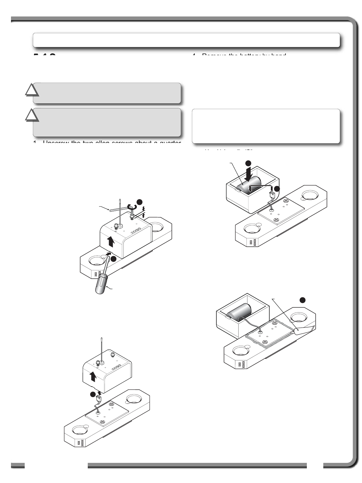
5.1a Replacing Sensor Battery
1. Unscrew the two allen screws about a quarter
of an inch.
2. Insert a flat bladed screwdriver in the battery
cover notch to pry the box away from the
mounting plate. The silicone seal may cause
some resistance.
3. The data wires of a load cell may be disconnected
to facilitate battery replacement.
4. Remove the battery by hand.
5. Remove the remaining silicone from both the
box and the mounting plate.
6. Install the new battery: insert the positive end and
then push in the direction of the positive pole.
7. Reconnect the data wires if disconnected.
8. Apply a non-corrosive RTV silicone all around
the edge of the mounting plate to create a new
seal without bubbles or breaks.
9. Reposition the box over the mounting plate and
screw in the hex screws. Do not overtighten.
5.
5. MAINTENANCE
MAINTENANCE
1/4 in.
1
2
Hex key 5/32 in.
Flat bladed screwdriver
6
7
New high quality “D”
cell battery: 3.6 V lithium,
or alkaline
Figure: Remove the sensor box from the mounting plate
3
Figure: Disconnect the data wires
8
RTV non-corrosive
silicone
Figure: Install the new battery and reconnect the data wires
Figure: Apply non-corrosive RTV silicone
IMPORTANT!
Protect the interior of the
sensor from dirt and humidity at all times.
!
!
Note: A 3.6 volt lithium “D” cell battery will provide
about two years of battery life for a load cell, while
an alkaline “D” cell battery will provide less than
one year of battery life*.
IMPORTANT!
Both lithium or alkaline
batteries can be used, however lithium
battery will last about 2.5 times longer.
!
!
* Actual battery life will vary greatly depending on
the application, the frequency of use, the age and
quality of the battery etc.
30
30 The GS22X System
The GS22X System
5.2
5.2 Anti-Two-Block switch
Anti-Two-Block switch
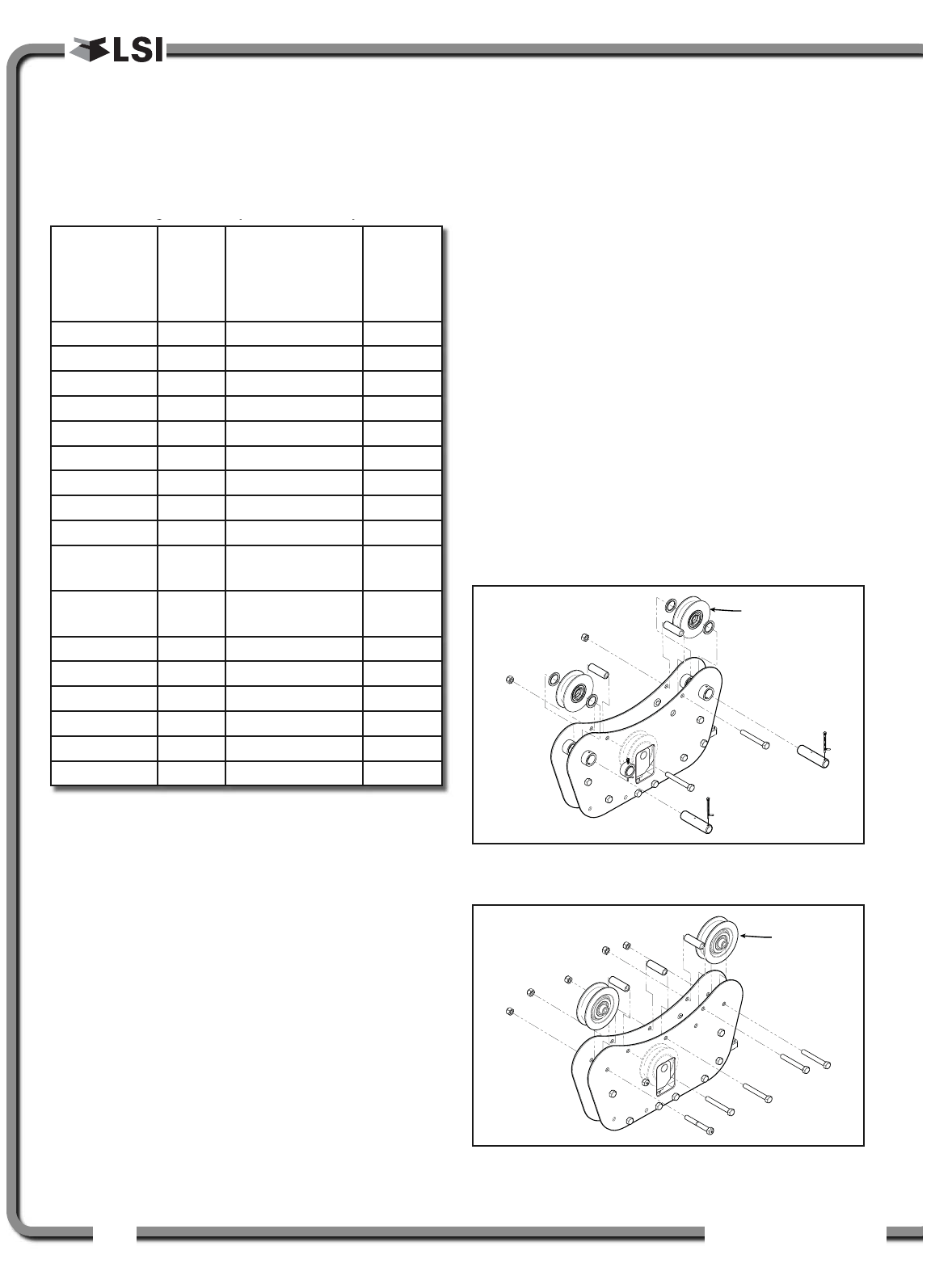
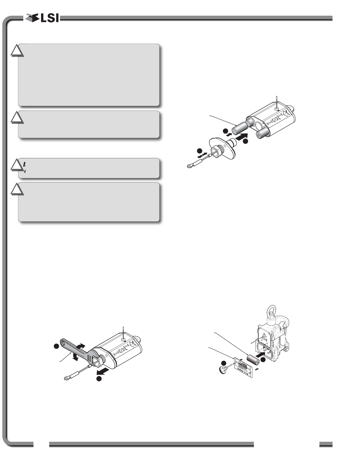
5.2a Replacing the GS050 Batteries
This procedure does not apply to the GS005
mechanical anti-two-block transmitter; please refer
to the Replacing Sensor Battery section.
1. Remove the anti-two-block from the crane and
clean off dust and grime.
2. Place the anti-two-block on the edge of flat
surface. Use an adjustable wrench to unscrew
the large white nylon hex bolt of the wire rope
about one half-inch.
3. Carefully remove the plunger assembly without
separating it from the cover, and place it on a
clean and dry surface.
4. Slide out the four old batteries.
5. Insert the four new batteries following the
positive - negative schematic printed on the
back of the sensor.
6. Replace the plunger assembly. Correctly align
the bottom cover before screwing in the white
nylon hex bolt of the wire rope. Tighten well.
7. Pull and release the wire rope, the light emitting
diode (LED) on the bottom of the sensor should
flash red.
8. Reinstall the anti-two-block switch.
9. Test the anti-two-block system for alarm and
lockout before operating the machine.
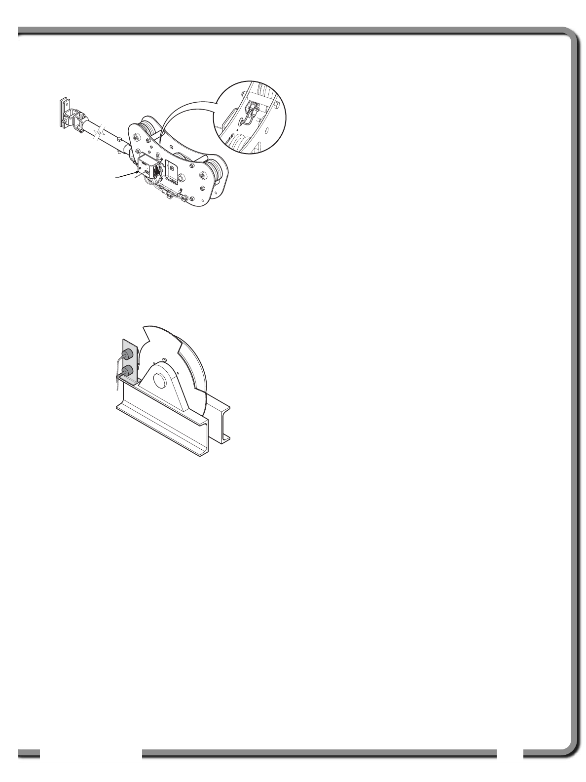
5.2b Replacing the GS075 Battery
1. Remove the GS075 anti-two-block from the
crane and clean off dust and grime.
2. Unscrew the two screws of the battery cover
and remove the battery cover.
3. Remove the battery by hand.
4. Insert the new battery following the positive -
negative schematic.
5. Reposition the battery cover and screw in both
screws.
6. Reinstall the anti-two-block switch.
7. Test the anti-two-block system for alarm and
lockout before use.
2
3
A
djustable
wrench
Figure: Remove the plunger assembly of the GS050
6
5
7
New high quality “C”
cell battery: 3.6 V lithium,
or alkaline
Figure: Install the new batteries and the plunger
IMPORTANT!
Replace all the batteries of
the anti-two-block switch at the same time.
Unchanged batteries will reverse polarity
severely reducing battery life.
IMPORTANT!
Protect the interior of the
anti-two-block switch from dirt and humidity
at all times.
!
!
IMPORTANT!
Do not unscrew the white
nylon hex bolt of the antenna.
IMPORTANT!
Do not unscrew the small
screw to the left of the antenna.
!
!
IMPORTANT!
Class I Div I sensors certified by
CSA or ATEX should use alkaline batteries only.
!
!
New high quality “D”
cell battery: 3.6 V lithium,
or alkaline
Battery
cover
4
2
Figure: Replacing GS075 battery
IMPORTANT!
Both lithium or alkaline
batteries can be used, however lithium
battery will last about 2.5 times longer.
!
!

ISTALLATIO
ISTALLATIO 31
31
5.3
5.3 Replacing a Sensor
Replacing a Sensor
Antenna
Antenna
Heavily damaged antennas (ripped out, sheared off,
wire exposed and fraying etc.) should be replaced
to ensure effective communication between the
sensor and the cabin mounted display unit.
This procedure may be followed without removing the
sensor from the crane if it is safe to do so. If removed,
an angle sensor must be re-calibrated during
reinstallation for correct angle display (see the angle
sensor installation section of the user’s manual).
1. Place the crane, boom, jib or ball hook such that
the sensor is safely accessible.
2. Clean dust, grime and water from the sensor.
3. Identify the short black whip antenna and the
white hex bolt securing it.
4. Inspect the antenna for signs of obvious
physical damage.
5. Carefully unscrew the white nylon hex bolt
completely and slide it up the antenna.
6. Grip the antenna by the base of the black plastic
sheathing and pull it straight out of the hole in
which it is seated. Place the old antenna aside.
7. Slide the white nylon hex bolt to the middle of
the length of the new antenna.
8. Coat the exposed metal foot of the new antenna
with an electrical insulating compound by
carefully inserting it in the mouth of the
compound tube.
9. Hold the new antenna by the black plastic
sheathing and guide it through the hole in the
sensor box. Carefully seat the antenna in its
mating connector. When the antenna is
correctly seated, pulling on it will be met with
light resistance.
10.Carefully re-thread, screw-in and tighten the
white nylon hex bolt to secure the antenna in
place. Do not overtighten.
11. Reinstall the sensor if necessary (if removed
from the boom or jib, an angle sensor will
require re-calibration during the installation
procedure, see the angle sensor installation
section of the user’s manual).
12.Verify that the sensor functions properly.
5
7/16 in.
wrench
Figure: Unscrew the white nylon hex
6
Figure: Pull out the antenna
8
Electrical insulating
compound
Figure: Coat the exposed metal foot of the antenna
White nylon hex bolt
TA011 Antenna
Sensor box
Antenna receptacle
Figure: Install the new antenna
IMPORTANT!
The interior of the sensor
must be protected from dust, grime and water
at all times.
32
32 The GS22X System
The GS22X System
5.4
5.4 Load Cells
Load Cells
5.4a Reading Accuracy
LSI
LSI flat bar load links are pre-calibrated at the
factory. No “zeroing” or other calibration is required
on installation. Each link is heat treated to age the
steel and ensure stable readings for many years; the
load cells are individually temperature compensated
to guarantee accuracy. LSI
LSI flat bar load links are
calibrated to indicate between 100% and 104% of
their Safe Working Load (SWL).
LSI
LSI load pins, line riding tensiometers and
compression cells must be calibrated at installation
and every time thereafter the installation, the load
sensor or the transmitter is changed.
SAE J 159 4.2.1 recommends load indicating
devices should show not less than 100% of the
actual load and not more than 110% of the actual
load.
5.4b Load Testing
LSI
LSI recommends testing the load cell every year for
accuracy. The simplest way of testing a load cell is to
lift at least two known weights. A test weight should be
known with an accuracy of ±1%. If the load cell is
installed at the boom tip dead end, all additional
equipment such as blocks, slings, sensors, etc. should
also be known to an accuracy of ±1%.
Determine the accuracy of the tested system with
the following formula:
(Reference: SAE-J-159 7.3)
The test loads must be significantly relative to the
load cell capacity. The minimum test weight is
about 20% of the safe working load; a good test
weight is greater than 50% of the SWL. For
example, a 30 000 lb load cell on four parts of line
has a SWL of 120 000 lb; the minimum test load in
this case would be 24 000 lb, a good test load
would be 60 000 lb or more.
5.4c Care
Battery. Lithium batteries older than 18 months old
(alkaline batteries over 6 months old) should be
changed at the first available planned inspection
even if there is not yet a low battery warning. This
will avoid costly delays in the field.
Corrosion. Verify that no corrosion is visible on the
battery holder inside the load cell transmitter. If some
trace of corrosion is visible, rub it off gently and put
a small amount of dielectric grease* on each battery
holder post to protect the contacts.
Mechanical stresses. Verify the load cell sides for
dents or heavy scratches. The side of the load cell
under the transmitter box is the most sensitive
region. Engraving a number in this area will affect
load cell accuracy and reliability. If the transmitter
box has been hit and the box does not fit perfectly to
the underlying link, please call LSI
LSI to have it
repaired. Engraving on the transmitter box sides will
not affect reading.
Seal. If the transmitter box has been removed it
must be correctly resealed with RTV non-corrosive
silicone.
Antenna. Small scratches on the antenna will not
affect radio communications. A heavy bending of the
antenna or bare sections on the wire may reduce
the radio efficiency.
Hex bolts. The hex head bolts on the transmitter
box are there to protect the antenna and to hold the
transmitter box on the load cell link. If one or both
hex nuts are scratched, it will not affect the load cell
readings or operation. If the bolt head is bent or
sheared verify that the transmitter box fits tightly to
the load cell link before contacting LSI
LSI for
replacement bolts.
Indicated Load
Actual Load X 100 = % of Load
* Dow Corning dielectric grease №4
WARNING!
Heavy shock may affect load
indication accuracy. Inspect the load cell
regularly for clearly visible dents or
scratches. Test the load indication if collision
damage is visible.
!
!
34
34 The GS22X System
The GS22X System
7.1
7.1 FCC and IC – Instructions
FCC and IC – Instructions
to the User
to the User
This equipment has been tested and found to comply
with the limits for a class B digital device, pursuant to
part 15 of the FCC Rules. These limits are designed
to provide reasonable protection against harmful
interference in a residential installation. This
equipment generates, uses, and can radiate radio
frequency energy and if not installed and used in
accordance with the instructions, may cause harmful
interference to radio communications. However,
there is no guarantee that interference will not occur
in a particular installation. If this equipment does
cause harmful interference to radio or television
reception, which can be determined by turning the
equipment off and on, the user is encouraged to try
to correct the interference by one or more of the
following measures:
• Reorient or relocate the receiving antenna.
• Increase the separation between the equipment
and receiver.
• Connect the equipment into an outlet on a
circuit different from that to which the receiver is
connected.
• Consult the dealer or an experienced radio/TV
technician for help.
In order to maintain compliance with FCC
regulations, shielded cables must be used with this
equipment. Operation with non-approved equipment
or unshielded cables is likely to result in interference
to radio and TV reception.
FCC ID: QVBGS200 IC: 7076A-ICGS200
RF Exposure Warning:
This product complies with FCC/IC radiation
exposure limits set forth for an uncontrolled
environment. To comply with RF exposure
requirements, the unit must be installed and
operated with 20 cm (8 in.) or more between the
product and your body. This product may not be
collocated or operated in conjunction with any
other antenna or transmitter.
This device has been designed to operate with
the antennas listed below, and having a
maximum gain of 3.0 dB. Antennas not included
in this list or having a gain greater than 3.0 dB
are strictly prohibited for use with this device.
The required antenna impedance is 50 ohms.
To reduce potential radio interference to other
users, the antenna type and its gain should be
so chosen that the equivalent isotropically
radiated power (e.i.r.p.) is not more than that
permitted for successful communication.
Antenna List
LSI P/N: TA011
Description: 1/4 wave monopole
MFG Load Systems International
FCC ID: QVBGS000 IC: 7076A-ICGS000
FCC ID: QVBGS050 IC: 7076A-ICGS050
FCC ID: QVBGS075 IC: 7076A-ICGS075
RF Exposure Warning:
This product complies with FCC/IC radiation
exposure limits set forth for an uncontrolled
environment. To comply with RF exposure
requirements, the unit must be installed and
operated with 20 cm (8 in.) or more between the
product and your body. This product may not be
collocated or operated in conjunction with any
other antenna or transmitter.
This device has been designed to operate with
the antennas listed below, and having a
maximum gain of 3.0 dB. Antennas not included
in this list or having a gain greater than 3.0 dB
are strictly prohibited for use with this device.
The required antenna impedance is 50 ohms.
To reduce potential radio interference to other
users, the antenna type and its gain should be
so chosen that the equivalent isotropically
radiated power (e.i.r.p.) is not more than that
permitted for successful communication.
Antenna List
LSI P/N: TA011
Description: 1/4 wave monopole
MFG Load Systems International
7.
7. CERTIFICATION NOTES
CERTIFICATION NOTES
IMPORTANT!
Changes or modifications to
this equipment not expressly approved by the
party responsible for compliance could void
the user’s authority to operate the equipment.
!
!

ISTALLATIO
ISTALLATIO 35
35
8.1
8.1 Limited Warranty
Limited Warranty
LOAD SYSTEMS INTERNATIONAL INC. (hereafter
“LSI
LSI”) warrants its products (the “Products”), for a
period of twenty four (24) consecutive months after
delivery of such Products to the user (as evidenced
on a LSI
LSI document) (the “Warranty Period”), when
installed and used in accordance with specifications
described in LSI
LSI Installer and User’s Manual, as
amended from time to time , LSI
LSI technical materials
and any related writings published by LSI
LSI with
respect with such Products and any industry
standards, will be free from defects in materials and
workmanship. During the Warranty Period, LSI
LSI or its
designated service representative shall repair, or at
its option, replace any Product that is confirmed to be
defective by LSI
LSI, in its sole discretion, in accordance
with the Limited Warranty Services Procedures
described below.
8.2
8.2 Warranty Services
Warranty Services
Procedures
Procedures
In order to benefit of this-mentioned Limited Warranty
coverages and benefits, the purchaser must notify
LSI
LSI’s customer service or LSI
LSI’s authorized distributor
or representative originally responsible for the sale of
the Products within 10 days of the occurrence of a
suspected defect in materials or workmanship, prior
to the expiry of the Limited Warranty Period in order
to obtain a Return Authorization Number. A proof of
purchase of the Product, such as an invoice or a
receipt certifying the validity of the Warranty, must be
presented in order to obtain Limited Warranty
coverage. In any event, even if a Return Authorization
Number is provided to purchaser, LSI
LSI reserves the
right to inspect the damaged Product or part before
the final decision of repairing or replacing the
defective Product or part.
The Product or part shall be returned to LSI
LSI or its
designated service representative, accompanied by
the Return Authorization Number with prepaid
shipping charges. The purchaser must insure the
shipment or accept the risk of loss or damage during
the shipment. Purchaser shall also pay any tariff or
duty applicable to the return of defective part or
Product. LSI
LSI will, at its option, repair or replace the
Product or part returned to LSI
LSI or to its designated
service representative. LSI
LSI owns all parts or Products
replaced, repaired or removed from a repaired
Product. If LSI
LSI repairs a Product, the Product
Warranty coverage Period is not extended and the
Limited Warranty shall expire as if uninterrupted upon
the occurrence of the 24th month from shipping from
LSI
LSI. If LSI
LSI replaces a Product, the replaced Product
is warranted for the remainder of the original term or
sixty consecutive (60) days, whichever is longer.
LSI
LSI reserves the right to require from you the user or
owner of the Products, prior to determining if the Limited
Warranty coverage is applicable, that LSI
LSI receive the
data logging equipment used with the Products and that
LSI
LSI be authorized to retrieve all information from such
data logging equipment in order to, among others,
ensure that the written instructions and applicable
standards, including safety margins, were respected
and not exceeded during Product use. Failure by you
the owner or user of the Product to supply such
information shall be deemed a material default of the
terms and conditions of this Limited Warranty and shall
be irrevocably construed as evidence that the Product
was misused or abused. Consequently LSI
LSI shall
irrevocably be relieved of any obligations to
compensate you the user or owner of the Product for
any and all damages resulting from Product failures
when data logging equipment, and access to its
content, cannot be freely and readily provided,
unhampered, to LSI
LSI.
LSI
LSI will pay ground freight transportation costs
of replacement or repaired parts or Products to
the destination in Canada and the continental
United States of America (the “Territory”). LSI
LSI will
not pay any transportation costs of replacement
or repaired parts to destination outside of the
Territory. Shipping and handling costs to
locations outside the Territory shall be the
responsibility and borne by Purchaser or Owner
of the Product prior to any shipment by LSI
LSI.
(Contact LSI
LSI to get a Return Authorization
Number and the address to ship parts).
8.3
8.3 Exclusion of Other
Exclusion of Other
Warranties
Warranties
THE ABOVE WARRANTY IS THE SOLE WARRANTY
APPLICABLE AND THERE ARE NO EXPRESS,
LEGAL OR IMPLIED WARRANTIES OR CONDITIONS
IN RELATION TO ANY PRODUCTS INCLUDING ANY
IMPLIED WARRANTY OR CONDITION OF
MERCHANTABILITY, NON-INFRINGEMENT OR
FITNESS FOR A PARTICULAR PURPOSE AND
THOSE OTHERWISE ARISING BY STATUTE OR
OTHERWISE IN LAW OR FROM A COURSE OF
8.
8. LSI PRODUCT LIMITED WARRANTY - 2009/02/16
LSI PRODUCT LIMITED WARRANTY - 2009/02/16

36
36 The GS22X System
The GS22X System
DEALING OR USAGE OF TRADE, WHICH ARE
EXPRESSLY DISCLAIMED. NO ORAL OR WRITTEN
INFORMATION OR ADVICE GIVEN BY LSI
LSI OR ITS
EMPLOYEES OR REPRESENTATIVES SHALL
CREATE A WARRANTY OR CONDITION OR IN ANY
WAY INCREASE THE SCOPE OF LSI
LSI’S OBLIGATION.
LSI
LSI DOES NOT WARRANT THAT THE BUSINESS
RESULTS OBTAINED FROM THE USE OF THE
PRODUCTS WILL BE APPROPRIATE OR ADEQUATE
FOR THE PURCHASER.
8.4
8.4 Exclusion
Exclusion
This Limited Warranty does not cover and shall not
apply to:
• Any Product that is misused or abused, including
being altered, modified or repaired not in
accordance to LSI
LSI written instructions or
authorizations and any use not in compliance with
LSI
LSI’s instructions and/or industry standards and
practices;
• Any incidental costs or expense, such as shipping
charges to LSI
LSI or an designated service
representative as well as the technician out-of-
pocket expenses including traveling, lodging and
meal expenses, if any;
• The damages caused during the transport or the
moving of the Products;
• Damages caused by accidents, abuse, misuse, a
force majeure (described as events outside a
LSI
LSI’s or any Product user’s control, including war,
riot, strikes, embargoes) or external cause;
• Any cost, damage or expenses for field labor or
any other expenses related to or arising from the
replacement of defective parts.
• Products used for pile-driving, wire rope activated
clamshell or dragline applications. If purchaser
uses the Products for pile-driving, wire rope
activated clamshell or dragline application, the
limited warranty will be deemed to have been
violated for abuse.
• Any costs associated with providing LSI
LSI with data
logging equipment.
8.5
8.5 Limitation of Liability
Limitation of Liability
To the maximum extent permitted by applicable law,
in no event will LSI
LSI be liable to the purchaser or any
third party for any indirect, special, consequential,
incidental or exemplary damages whatsoever,
including but not limited to loss or revenue or profit,
lost or damaged data, business interruption or any
other pecuniary loss whether based in contract, tort or
other causes of action, even if LSI
LSI has been advised
of the possibility of such damages. In any event, the
total liability of LSI
LSI arising from any cause of action or
claim whatsoever, whether (1) in contract, (2) in tort
(including negligence, whether sole, joint,
contributory, concurrent or otherwise, but not
including intentional, reckless or wanton tort), (3)
under strict liability, (4) under any environmental or
antipollution law or regulation, (5) connected with any
toxic or hazardous substance or constituent, (6)
arising out of any representation or instruction, or
under any warranty, (7) or otherwise, arising out of,
connected with, or resulting from the design,
manufacture, sale, resale, delivery, repair,
replacement or use of Products or the furnishing of
any service shall in no event exceed the price
allocable to and paid to LSI
LSI for the individual unit of
Products or service or part thereof which gives rise to
the cause of action or claim.
SOME STATES OR JURISDICTIONS DO NOT
ALLOW THE LIMITATION OR EXCLUSION OF
LIABILITY FOR INCIDENTAL OR CONSEQUENTIAL
DAMAGES, SO THE ABOVE LIMITATION OR
EXCLUSION MAY NOT APPLY TO YOU.
8.6
8.6 Recommended Practices
Recommended Practices
LSI
LSI recommends careful consideration of the
following factors when specifying and installing the
Products. Before installing a Product, the Installation,
Operation, and Maintenance instructions provided
with the unit must be read and understood and
complied with.
8.7
8.7 Choice of law
Choice of law
This Limited Warranty shall be governed by and
construed in accordance with the laws of : 1. For
Products sold in Canada: the Province of Quebec or,
For Products sold in the USA: the State of Florida,
without giving effect to principles of conflicts of law.
You agree that the exclusive venue for any disputes
arising under this Agreement shall be the state and
federal courts located in Orlando, Florida.
8.7a Entire Agreement
This document contains the entire agreement of the
parties regarding the subject matter of the Product
and supersedes all previous communications,
representations, understandings and agreements,
either oral or written, between you and LSI
LSI.

GM22X REV.20090603 www.loadsystems.com
© 2009, Load Systems International Inc.
Technical Support:
Technical Support:
LSI
LSI Technical Support is available 24 hours a day, 7 days a week from our
Houston and Dubai locations.
Please direct all technical support questions to either of these locations or
contact us via email:
techsupport@loadsystems.com
North America Middle East & Africa
Toll Free Phone: (888) 819 4355 Phone: +971 6 557 8314
Toll Free Fax: (888) 238 4099 Fax: +971 6 557 8315
International: +1 (281) 664 1330
LSI Contact Information
LSI Contact Information
USA Corporate Office:
9223 Solon, Suite A
Houston, TX 77064
Direct Phone: 281.664.1330
Direct Fax: 281.664.1390
Email: sales@loadsystems.com
Dubai Corporate Office:
Q3-171 SAIF Zone. PO Box 7976
Sharjah UAE
Phone: +971 6 557 8314
Fax: +971 6 557 8315
Email: lsifzc@emirates.net.ae
Canadian Corporate Office:
4495 Blvd. Hamel, Suite 110
Quebec QC G1P 2J7
Direct Phone: (418) 650 2330
Direct Fax: (418) 650 3340
Email: sales@loadsystems.com