Locata LOCLITEG4 LocataLite G4 User Manual LocataLite User s Manual
Locata Corporation Pty Ltd LocataLite G4 LocataLite User s Manual
Locata >
User Manual

LocataLite User's Manual
Locata-LocataLite-UserManual v8r0
27-May-2014
2
Revision History:
Revision
Date
Revised By
Comments
v7r0
14-Nov-2012
JWB, IS
Initial external release
v8r0
16-May-2014
JG
Major update for v8r0 S/W release
V8r0
27 May 2014
MS
Updated regulatory information
Copyright
© Copyright Locata Corporation 2014. All rights reserved.
Not to be reproduced without the written consent of Locata
Corporation
All information contained in this document is carefully prepared and
offered in good faith as a guide in the installation, use, and servicing of
our products. Installers must ensure that the final installation operates
satisfactorily, within the relevant regulatory requirements.
We accept no responsibility for incorrect installation.
We reserve the right to change products, specifications, and
installation data at any time, without notice.

LocataLite User's Manual
Locata-LocataLite-UserManual v8r0
27-May-2014
3
Table of Contents:
CHAPTER 1 INTRODUCTION ............................................................................................................ 9
1.1. Scope ...................................................................................................................................... 9
1.2. System Overview .................................................................................................................. 9
1.3. Compatibility ...................................................................................................................... 10
1.4. Document Overview ........................................................................................................... 10
1.4.1. Organization ............................................................................................................... 10
1.4.2. Document Conventions ............................................................................................... 10
1.5. Regulatory Information ..................................................................................................... 11
1.5.1. FCC Guidelines for Devices Containing a Transmitter Module ............................... 11
1.5.2. External Antenna Integration ..................................................................................... 12
1.6. References ........................................................................................................................... 13
1.6.1. Locata References ...................................................................................................... 13
1.6.2. External References .................................................................................................... 13
CHAPTER 2 LOCATALITE CHARACTERISTICS .............................................................................. 15
2.1. Device Overview ................................................................................................................. 15
2.2. Operational Modes ............................................................................................................. 16
2.3. Physical Layout .................................................................................................................. 17
2.4. Electrical Interface ............................................................................................................. 18
2.4.1. Power Interface .......................................................................................................... 19
2.4.2. RF Interfaces .............................................................................................................. 19
2.4.3. RS-232 Interfaces ....................................................................................................... 19
2.4.4. LAN (Ethernet) Interface ............................................................................................ 20
2.4.5. USB Interface ............................................................................................................. 22
2.4.6. Auxiliary Port Interfaces ............................................................................................ 22
2.5. LED Status Indicators ....................................................................................................... 24
2.5.1. LED 1 – Logging Status ............................................................................................. 26
2.5.2. LED 2 – Network Synchronization ............................................................................. 26
2.5.3. LED 3 – Health and Tracking Status ......................................................................... 27
2.5.4. LED 4 – Position Self-Survey Status .......................................................................... 27
2.5.5. LED 5 – Application Status ........................................................................................ 28
2.5.6. LED 6 – Device Status ................................................................................................ 29
2.5.7. LED 7 – Heartbeat Indication .................................................................................... 30
CHAPTER 3 LOCATALITE INSTALLATION .................................................................................... 31
3.1. Physical Installation ........................................................................................................... 31
3.2. Network Configuration ...................................................................................................... 31
3.3. LocataLite Configuration File .......................................................................................... 31
3.4. Communications Interface Configuration ....................................................................... 32
3.4.1. Ethernet Interface ....................................................................................................... 32
3.4.2. COM Port Interface .................................................................................................... 34
3.5. Determining the Current Configuration .......................................................................... 35
3.6. Optional LocataLite Configurations ................................................................................ 36

LocataLite User's Manual
Locata-LocataLite-UserManual v8r0
27-May-2014
4
3.6.1. GPS Synchronization (“GPS Sync”) .......................................................................... 36
3.6.2. Interfacing a Meteorological Station to a LocataLite ................................................ 40
3.6.3. Setting up LocataLite Self-Survey .............................................................................. 41
CHAPTER 4 LOCATALITE OPERATION ......................................................................................... 45
4.1. Starting Operations ............................................................................................................ 45
4.1.1. Master Startup ............................................................................................................ 45
4.1.2. Slave Startup ............................................................................................................... 46
4.2. Ceasing Operations ............................................................................................................ 46
4.3. Accessing the LocataLite via FTP .................................................................................... 47
4.4. Issuing Commands via FTP .............................................................................................. 48
4.5. Configuring the LocataLite ............................................................................................... 48
4.6. Accessing Log Files ............................................................................................................ 49
4.7. Upgrading the LocataLite Software ................................................................................. 49
4.8. Checking Version Information ......................................................................................... 50
4.9. LBMP via TCP ................................................................................................................... 50
4.10. Serial Communication ....................................................................................................... 51
4.11. Web Interface ..................................................................................................................... 52
CHAPTER 5 TROUBLESHOOTING ................................................................................................... 53
5.1. General Troubleshooting ................................................................................................... 53
5.2. Device Configuration Troubleshooting ............................................................................ 53
5.2.1. Communications Interface Troubleshooting .............................................................. 54
5.3. Troubleshooting the Position Reference GPS Receiver .................................................. 55
5.4. Troubleshooting the Timing Reference GPS Receiver ................................................... 55
5.4.1. uTevo GPS Receivers ................................................................................................. 55
5.4.2. TSC-4400 GPS Receivers ........................................................................................... 57
CHAPTER 6 MAINTENANCE ........................................................................................................... 58
6.1. Routine Maintenance ......................................................................................................... 58
CHAPTER 7 LOCATALITE SPECIFICATIONS .................................................................................. 59
CHAPTER 8 NOTES ......................................................................................................................... 61
8.1. Definitions ........................................................................................................................... 61
8.2. Acronyms and Abbreviations ............................................................................................ 62
APPENDIX A MESSAGE DEFINITIONS ....................................................................................... A-1
A.1 Standard Messages .......................................................................................................... A-1
A.1.1 GPS GSV Message .................................................................................................... A-2
A.2 Locata Proprietary Messages ......................................................................................... A-3
A.2.1 Locata ETH Message ................................................................................................ A-4
A.2.2 Locata ENV Message ................................................................................................ A-5
A.3 SigNav Proprietary Messages ........................................................................................ A-6
A.3.1 SigNav uTevo SSR Message ...................................................................................... A-6

LocataLite User's Manual
Locata-LocataLite-UserManual v8r0
27-May-2014
5
A.4 Leica Proprietary Messages ........................................................................................... A-8
A.4.1 Leica TPV Message ................................................................................................... A-8
A.4.2 Leica LVR Message ................................................................................................. A-12
APPENDIX B CONFIGURATION FILE ....................................................................................... B-13

LocataLite User's Manual
Locata-LocataLite-UserManual v8r0
27-May-2014
7
Table of Figures
FIGURE 1, SAMPLE FCC ID LABEL FOR DEVICES CONTAINING A LOCATALITE .................................... 12
FIGURE 2, THE LOCATALITE ................................................................................................................ 17
FIGURE 3, LOCATALITE FRONT PANEL ................................................................................................. 18
FIGURE 4, LOCATALITE REAR PANEL ................................................................................................... 18
FIGURE 5, SHIELDED ETHERNET CABLE DESIGN .................................................................................. 21
FIGURE 6, THE LOCATALITE SHOWING THE LEDS .............................................................................. 24
FIGURE 7, GPS SYNC CONNECTION ..................................................................................................... 36
FIGURE 8, RECOMMENDED SINGLE-ENDED TO DIFFERENTIAL CONVERSION CIRCUIT ............................ 37
FIGURE 9, UTEVO PANEL ..................................................................................................................... 38
FIGURE 10, TSC-4400 REAR PANEL ..................................................................................................... 40
FIGURE 11, LOCATALITE INTERCONNECTION WITH A MET STATION .................................................. 40
FIGURE 12, LOCATALITE-GPS INTERCONNECTION FOR SELF-SURVEY ................................................ 41
FIGURE 13, PERMISSIBLE ARRANGEMENT OF ANTENNAS WHEN SELF-SURVEYING ............................... 42

LocataLite User's Manual
Locata-LocataLite-UserManual v8r0
27-May-2014
8
Table of Tables
TABLE 1, ROVER OPERATIONAL MODES ............................................................................................... 16
TABLE 2, POWER CONNECTOR PIN ASSIGNMENTS ................................................................................ 19
TABLE 3, RS-232 INTERFACE CONNECTOR PIN ASSIGNMENTS ............................................................. 20
TABLE 4, LAN CONNECTOR PIN ASSIGNMENTS ................................................................................... 20
TABLE 5, USB CONNECTOR PIN ASSIGNMENTS .................................................................................... 22
TABLE 6, AUX-1 CONNECTOR PIN ASSIGNMENTS ................................................................................. 23
TABLE 7, AUX CONNECTOR PIN ASSIGNMENTS .................................................................................... 23
TABLE 8, LED PURPOSES .................................................................................................................... 24
TABLE 9, LED SEQUENCES .................................................................................................................. 25
TABLE 10, LED 1, LOGGING STATUS ................................................................................................... 26
TABLE 11, LED 2, NETWORK SYNCHRONIZATION STATUS ................................................................... 26
TABLE 12, LED 3, HEALTH & TRACKING STATUS ................................................................................ 27
TABLE 13, LED 4, POSITION SELF-SURVEY STATUS ............................................................................. 27
TABLE 14, LED 5, APPLICATION WARNINGS AND ERRORS ................................................................... 28
TABLE 15, LED 6, DEVICE STATUS ...................................................................................................... 29
TABLE 16, LED 7, HEARTBEAT INDICATIONS ...................................................................................... 30
TABLE 17, GSV MESSAGE FIELDS ...................................................................................................... A-2
TABLE 18, ETH MESSAGE FIELDS ...................................................................................................... A-4
TABLE 19, ENV MESSAGE FIELDS ..................................................................................................... A-5
TABLE 20, SSR FIELDS ...................................................................................................................... A-6
TABLE 21, TPV MESSAGE FIELDS ...................................................................................................... A-8
TABLE 22, TPV MESSAGE SOLUTION TYPE FIELD ........................................................................... A-10
TABLE 23, TPV MESSAGE, EXTERNAL AIDING FIELD ...................................................................... A-10
TABLE 24, TPV MESSAGE, FAILURE FLAG FIELD ............................................................................. A-11
TABLE 25, TPV MESSAGE POSITION FORMAT FIELD ........................................................................ A-11
TABLE 26, LVR MESSAGE FIELDS .................................................................................................... A-12

Chapter 1
Introduction LocataLite User's Manual
Locata-LocataLite-UserManual v8r0
27-May-2014
9
CHAPTER 1 INTRODUCTION
This document is a guide for installing and operating a LocataLite Model: ASY-010007-
1 as part of a LocataNet. Once configured the LocataNet provides a reliable, high-
accuracy positioning service independent of GPS or any other external positioning
system.
LocataLite devices provide a high degree of configuration flexibility allowing use in
wide range of operational scenarios. Locata suggests users spend time reading the
documentation to assist in achieving an optimal configuration of LocataLite devices and
networks.
1.1. Scope
This document covers the interfaces, installation, operation, and troubleshooting of
LocataLites based on hardware version 2
1
running software v8r0. Earlier LocataLite
hardware revisions and software releases are not covered in this document.
Additional sources of documentation are provided for LocataNet users as listed in the
References section. Of particular note are the Rover User Manual which provides
complete coverage of LocataLite devices, and the LocataNet User Manual which covers
recommended network configurations, site installation considerations, and other matters
external to the LocataLite housing itself.
1.2. System Overview
The Locata network provides a means of precisely geo-locating stationary or mobile
user navigation receivers (Rovers) within an operational area. Stationary LocataLite
transmitters provide signal coverage within this are which may span up to thousands of
square kilometers in size. Rovers calculate positions by measuring precise times of
arrival of the signals broadcast by LocataLites in view.
Each LocataLite transmits up to four signals across two frequencies in the license-free
2.4 GHz S-band using two physically separated antennas. All LocataLites in a given
network are time-synchronized to a designated Master LocataLite which may in turn
may use either its own internal timing or may synchronize itself, and therefore the entire
network, to an outside time source such as a GPS time receiver. This arrangement of
signals provides the advantages of both spatial and frequency diversity to network users.
Rover devices use the signals broadcast by LocataLites to position fully autonomously
using either code- or carrier-based techniques.
1
Hardware version 2 LocataLites have seven LEDs along one long edge.

Chapter 1
Introduction LocataLite User's Manual
Locata-LocataLite-UserManual v8r0
27-May-2014
10
1.3. Compatibility
LocataLites running software earlier than v8r0 are not compatible with units running
v8r0 software. When upgrading to v8r0 software from a version lower than v8r0, all
LocataLites in a given network must be upgraded together. Likewise the setup and
configuration files used with v8r0 software are not compatible with those of previous
versions of software.
1.4. Document Overview
1.4.1. Organization
Chapter 2 presents the characteristics of the LocataLite, including physical
characteristics, the LED flashing schemes, and connections to the LocataLite. Chapter 3
presents the information necessary to install and configure the LocataLite. Chapter 4
discusses operating the LocataLite, while Chapter 5 presents tips for troubleshooting and
Chapter 6 discusses maintenance. Appendix A presents serial message definitions in
common use with the LocataLite. Appendix B provides a further reference for
configuration options by including the contents of a standard Rover configuration file.
1.4.2. Document Conventions
This document uses the Courier New font, such as config.txt, to refer to files,
directories, or parameters.
It uses the Courier New font with a grey highlight, such as IO_PORT_NMEA or
115200 to refer to parameter values.
Code, command, or data output examples are shown in a grey box in courier new font,
as for example:
$GPGSA,A,3,04,05,,,,,,,,,,,2.5,1.3,2.1*39

Chapter 1
Introduction LocataLite User's Manual
Locata-LocataLite-UserManual v8r0
27-May-2014
11
1.5. Regulatory Information
FCC Statement and Declaration: Locata Corporation declares that this device
complies with Part 15 of the FCC Rules and Regulations. Operation of this device is
subject to the following two (2) conditions:
1. This device may not cause harmful interference.
2. This device must accept any interference received, including interference that may
cause undesired operation.
FCC Caution: Any changes or modifications made to this device that are not expressly
approved by the manufacturer may void the user’s authority to operate the equipment.
Professional Installation and Antenna Notice: To comply with FCC regulations, this
device must be professionally installed in accordance with Reference 2, must be used in
conjunction with a Locata-approved antenna as per Section 1.5.2 and a Locata-approved
LAN cable as per Section 2.4.4.
FCC Modular Approval: This device has been granted Modular Approval, with the
condition that the device must:
Be professionally installed in accordance with Reference 2,
Follow labeling requirements detailed in Section 1.5.1,
Used in conjunction with a Locata-approved antenna as per Section 1.5.2,
Used in conjunction with a Locata-approved LAN cable as per Section 2.4.4.
FCC RF Radiation Exposure Statement: This equipment complies with FCC
radiation exposure limits set forth for an uncontrolled environment. End users must
follow the specific operating instructions for satisfying RF exposure compliance. This
transmitter must be at least 20 cm from the user and must not be co-located or operating
in conjunction with any other antenna or transmitter.
1.5.1. FCC Guidelines for Devices Containing a
Transmitter Module
The following is an extract from FCC PART 15 UNLICENSED MODULAR
TRANSMITTER APPROVAL, DA 00-1407, Released: June 26, 2000, Section 6
describing labeling requirements for devices containing a modular transmitter.
Section 6. The modular transmitter must be labeled with its own FCC ID number,
and, if the FCC ID is not visible when the module is installed inside another device,
then the outside of the device into which the module is installed must also display a

Chapter 1
Introduction LocataLite User's Manual
Locata-LocataLite-UserManual v8r0
27-May-2014
12
label referring to the enclosed module. This exterior label can use wording such as
the following: “Contains Transmitter Module FCC ID: XYZMODEL₁” or “Contains
FCC ID: XYZMODEL₁.” Any similar wording that expresses the same meaning may
be used. The Grantee may either provide such a label, an example of which must be
included in the application for equipment authorization, or, must provide adequate
instructions along with the module which explain this requirement.
In the latter case, a copy of these instructions must be included in the application for
equipment authorization.
Figure 1, Sample FCC ID label for devices containing a LocataLite
1.5.2. External Antenna Integration
This device must be used in conjunction with a patch antenna presenting a 50 ohm load
impedance at the frequency of operation and exhibiting a maximum gain of less than
+5.0 dBi. The antenna must be fitted with a male SMA connector and professionally
installed in accordance with Reference 2. Operation of this device with any other type of
antenna is strictly prohibited.
Contains FCC ID: ARW-LOCLITEG4
Model : ASY-010007-1

Chapter 1
Introduction LocataLite User's Manual
Locata-LocataLite-UserManual v8r0
27-May-2014
13
1.6. References
1.6.1. Locata References
1. Locata Corporation, Rover User’s Manual, Locta-Rover-UserManual-v8r0, 16 May
2014
2. Locata Corporation, LocataNet Manual, v1 Draft, unreleased.
3. Locata Corporation, Locata Signal Interface Control Document, ICD-LOC-100E, 29
January 2014
4. Locata Corporation, Locata Binary Messaging Protocol Interface Control Document
(LBMP ICD), v2.32, 29 January 2014.
5. Locata Corporation, Locata DTM File Format Specification, v1.2, 2 December 2013.
1.6.2. External References
6. Vaisala, PTU300 website. http://www.vaisala.com/instruments/products/ptu300.html
7. SigNav, ICD 'SGN1-0020-NMEA-ICD-v2.7.pdf'
8. Symmetricom, TSC 4400 website.
http://www.symmetricom.com/products/gps-solutions/gps-time-frequency-
receivers/TSC-4400/
9. Symmetricom, TSC 4400 – GPS Disciplined Rb Oscillator Manual
http://www.symmetricom.com/link.cfm?lid=4407
10. Novatel OEM 4 User Manual – Volume 2, Command and Log Reference. OM-2000047
Rev 18
http://www.novatel.com/assets/Documents/Manuals/om-20000047.pdf

Chapter 2
LocataLite Characteristics LocataLite User's Manual
Locata-LocataLite-UserManual v8r0
27-May-2014
15
CHAPTER 2 LOCATALITE
CHARACTERISTICS
2.1. Device Overview
The LocataLite is the positioning signal transmitting element within a Locata network.
Once configured and powered on, it will begin transmissions automatically (after
TimeLoc to the Master in the case of Slave LocataLites), and operates continuously and
unattended for extended periods of time.
Each LocataLite transmits four low-power RF signals, one on each of two frequencies
from each of two transmitter antenna ports. The LocataLite’s transmissions are also
pulsed: each LocataLite transmits for a 100 microsecond pseudo-randomly assigned
period once in each 1 millisecond interval, and is silent for the remaining 900
microseconds.
A number of peripherals can support LocataLite operations though none are required for
standard operation. A GPS receiver can supply GPS timing (as pulse per second and
serial timing messages) to a Master LocataLite for network synchronization to GPS
time. A survey grade GPS receiver can supply antenna coordinates to LocataLites to
support a self-survey capability. A meteorological station can supply atmospheric data
to a LocataLite to allow estimation of tropospheric delay factors. Guidelines for using
these peripherals are included in Reference 2.
You can communicate with the LocataLite for health, status, and control using a binary
interface over an Ethernet or serial port.
The following sections discuss LocataLite installation, configuration, and operation in
more detail.

Chapter 2
LocataLite Characteristics LocataLite User's Manual
Locata-LocataLite-UserManual v8r0
27-May-2014
16
2.2. Operational Modes
Each LocataLite in a LocataNet operates as either a Master or Slave device. There is
only one Master in a given network and the remaining LocataLites act as Slave devices.
In general the LocataLite that is best placed to provide a timing reference for the
network should be designated as the Master LocataLite. That is, the Master should be
that LocataLite having the shortest paths to all other LocataLites, including using the
fewest TimeLoc hops where necessary. This arrangement provides the cleanest
TimeLoc performance operationally however there may be other reasons to select an
alternate Master device, such as accessibility or elevation.
Two different Master modes are provided to cater for scenarios where a network is
intended to operate fully autonomously or synchronized in time with GPS.
Mode #
Details
Master
Device acts as master time reference to which all other
LocataLite devices in the network synchronize.
Master with GPS
Sync
Device acts as master time reference to which all other
LocataLite devices in the network synchronize. Master
Device synchronizes with an external GPS time reference
creating GPS synchronization across the network.
Allows Rovers to compute navigation solutions based on
Locata measurements only or by combining measurements
from other navigation systems (eg GNSS such as GPS, INS).
Slave
Device synchronizes with network time reference provided by
the Master LocataLite.
Table 1, Rover operational modes
The operational mode of a LocataLite is selected through the configuration file
‘Device_Type’ parameter. Refer to Appendix B for further details on the LocataLite
configuration file.
Chapter 2
LocataLite Characteristics LocataLite User's Manual
Locata-LocataLite-UserManual v8r0
27-May-2014
17
2.3. Physical Layout
The LocataLite is enclosed within an aluminum package measuring 134 x 241 x 28 mm
and weighing 1.4kg. LocataLites are sealed units with no internal setting or adjustment.
Operators should not open the LocataLite case as this will void the warranty.
The LocataLite provides 9 electrical sockets comprising three digital sockets and 7
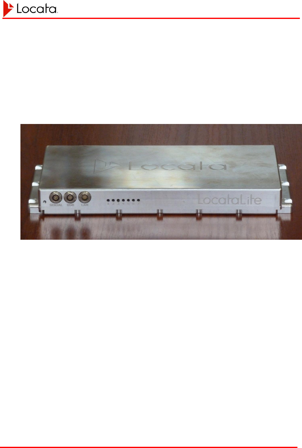
LEDs on the front panel, along with a further three digital and three RF sockets on the
rear panel. Figure 2 shows the LocataLite front face including status LEDs.
Figure 2, the LocataLite
Chapter 2
LocataLite Characteristics LocataLite User's Manual
Locata-LocataLite-UserManual v8r0
27-May-2014
18
2.4. Electrical Interface
LocataLite installation requires three coaxial antenna cables, a power cable, and an
Ethernet or serial cable. Master LocataLites using the GPS sync feature also require a
coaxial cable to connect the PPS input signal and a serial cable from the GPS clock
reference. LocataLites equipped with meteorological stations will require a serial cable
connecting the meteorological station to the LocataLite.
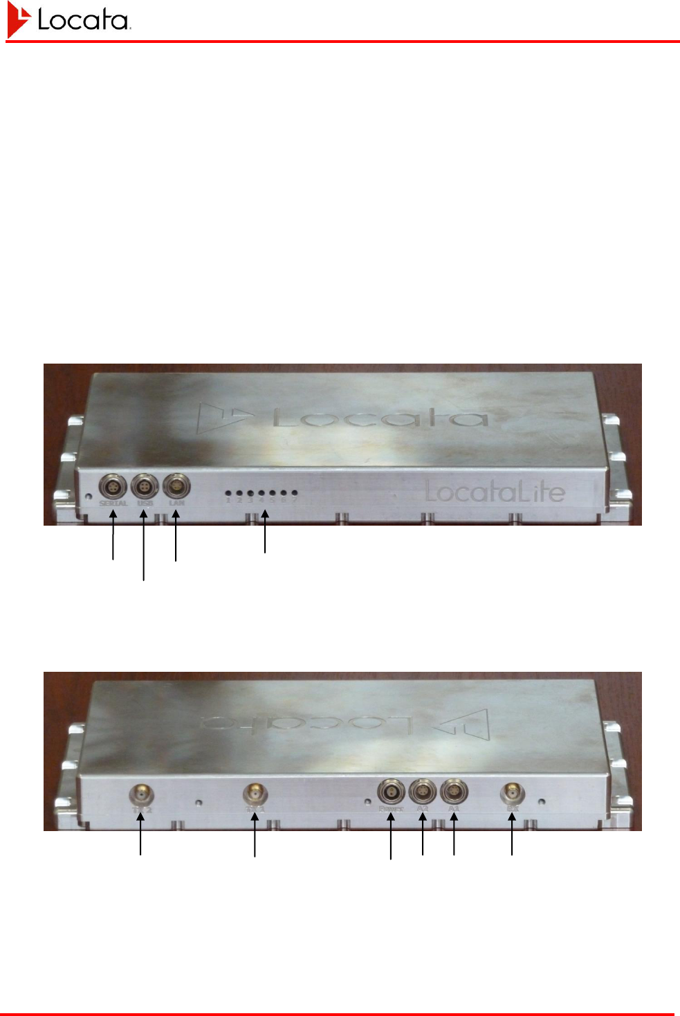
Figure 3 and Figure 4 illustrate the long edges of the LocataLite, where the serial, RF,
power, and auxiliary interfaces are found. All pin descriptions that follow show the
LocataLite connector as seen from the outside of the device. Pin 1 is marked by a
semicircle with pin numbering continuing counterclockwise.
Figure 3, LocataLite front panel
Figure 4, LocataLite rear panel
Serial Ports
Rx Antenna
Aux 1
Aux 2
Power
Tx Antenna 2
Tx Antenna 1
Ethernet Port
USB Port
LEDs

Chapter 2
LocataLite Characteristics LocataLite User's Manual
Locata-LocataLite-UserManual v8r0
27-May-2014
19
2.4.1. Power Interface
The LocataLite requires 12-28 volts DC for operation, and consumes approximately 40
watts. Supplied power should not exceed 29 volts DC. The LocataLite power
connection at the LocataLite case accepts a 2-pin LEMO connector (part number
FGG.0B.302). Power cable conductors should be sized to provide the power necessary
for the LocataLite, to sustain the maximum current draw safely, and provide no more
than a three percent conductor voltage drop round-trip from the DC power source.
Table 2, Power connector pin assignments
Pin #
Assignment
1
Vdc positive
2
Vdc ground
2.4.2. RF Interfaces
Antennas must be connected to the LocataLite using male SMA connectors. The
optimal antenna type will vary based on the application and environment. See
Reference 1.5.2 and Reference 2 for antenna and antenna cabling recommendations.
Operators should use an SMA torque wrench when connecting antennas to the
LocataLite to ensure a reliable connection without damaging the device. Also note the
recommendations in Reference 2 regarding antenna placement, cabling, and proper
coupling between the LocataLite receive and transmit antennas.
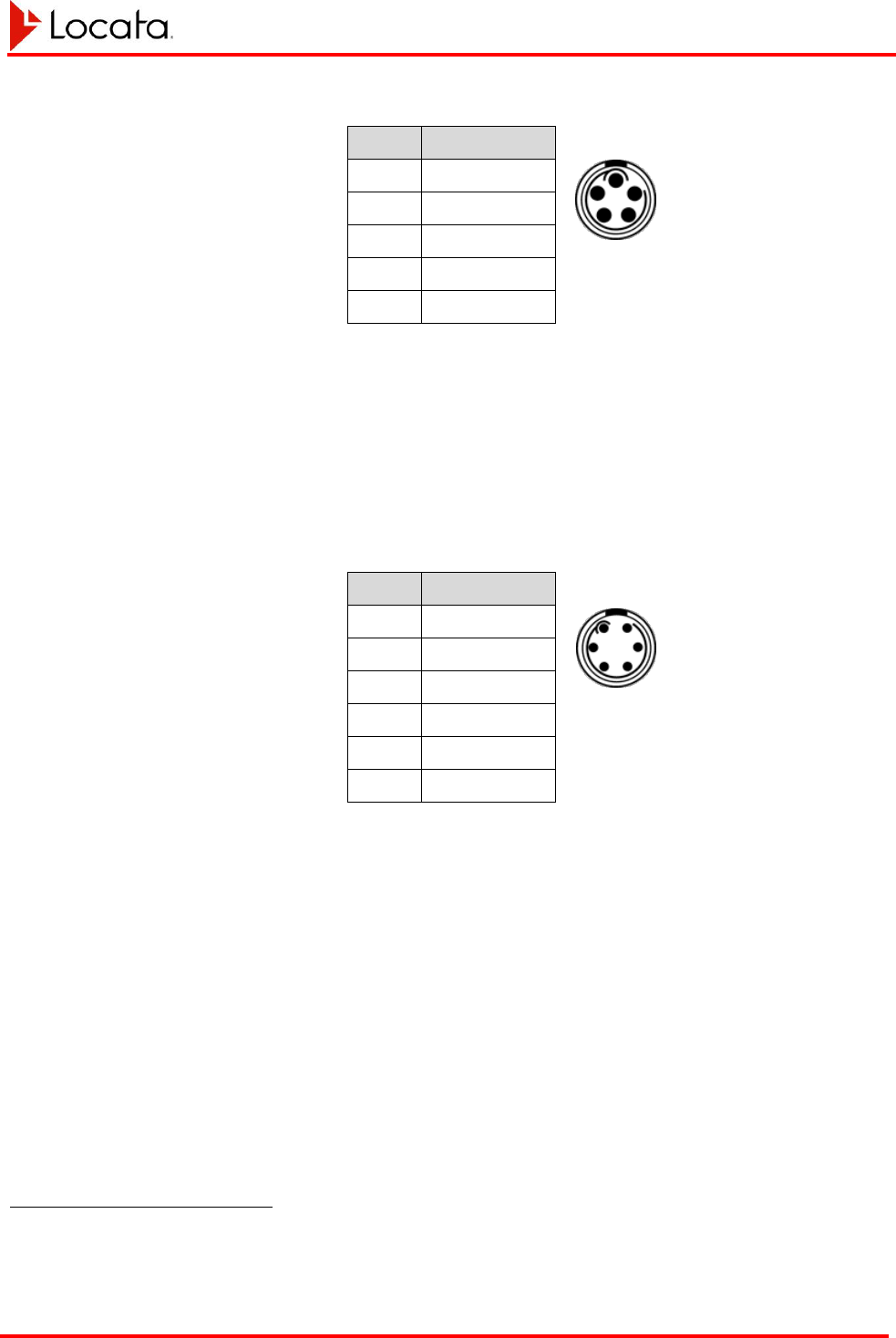
2.4.3. RS-232 Interfaces
The LocataLite makes two EIA/TIA-232 and V.28/v.24 compliant RS-232 serial ports,
COM1 and COM2, available using a single 5-pin LEMO connector (LEMO part number
FGG.0B.305) at the connector marked “Serial”. These ports can be used to connect
peripherals such as GPS receivers or MET stations to the LocataLite, or for you to
communicate with the LocataLite directly. Each port only implements transmit and
receive data lines at line levels of ±5 volts relative to ground. The LocataLite with its
serial cables is configured as DCE.
If it is necessary to use both RS-232 ports simultaneously, it will be necessary to employ
a Y-cable bringing out COM1 and COM2 to separate serial connectors. Assuming DB-9
socket serial connectors are used, TX1 and RX1 at the LEMO socket go to pins 2 and 3
respectively of DB-9 #1, and TX2 and RX2 at the LEMO socket go to pins 2 and 3
respectively of DB-9 #2. Pin 1of the LEMO socket, GND, would be wired to pin 5 of
both DB-9 sockets.
Chapter 2
LocataLite Characteristics LocataLite User's Manual
Locata-LocataLite-UserManual v8r0
27-May-2014
20
Table 3, RS-232 interface connector pin assignments
Pin #
Assignment
1
GND
2
TX1
3
RX1
4
RX2
5
TX2
2.4.4. LAN (Ethernet) Interface
Use a CAT5 cable terminated in a LEMO part number FGG.0B.306 LEMO connector to
connect to the LocataLite’s Ethernet interface. This interface supports 10 and 100
Megabits/second and 1 Gigabits/second data rates.
Table 4, LAN connector pin assignments
Pin #
Assignment
1
ext clock -
2
Tx+
3
Tx-
4
Rx-
5
Rx+
6
Ext clock +2
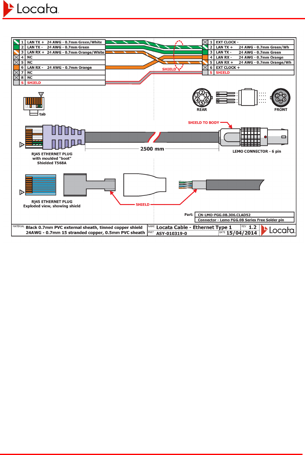
Figure 5 illustrates the required Ethernet cable wiring. Note that this connection
requires a shielded cable.
2
10-20 MHz clock
Chapter 2
LocataLite Characteristics LocataLite User's Manual
Locata-LocataLite-UserManual v8r0
27-May-2014
21
Figure 5, Shielded Ethernet cable design
Chapter 2
LocataLite Characteristics LocataLite User's Manual
Locata-LocataLite-UserManual v8r0
27-May-2014
22
2.4.5. USB Interface
The LocataLite has provision for a USB interface and acts as a USB host device. This
interface complies with USB1.1 and USB 2 standards.
The USB port is presently inoperative. Its implementation is reserved for a future
release.
Table 5, USB connector pin assignments
Pin #
Assignment
1
D-
2
GND
3
Vcc
4
D+
2.4.6. Auxiliary Port Interfaces
Two Auxiliary ports are available for specific supplemental connections. The following
subsections describe their present configurations. Other uses are possible in future for
specific applications.
All inputs must be differential. Many signal sources such as the PPS output on a GPS
receiver will be single ended. To convert from single ended to differential signal Locata
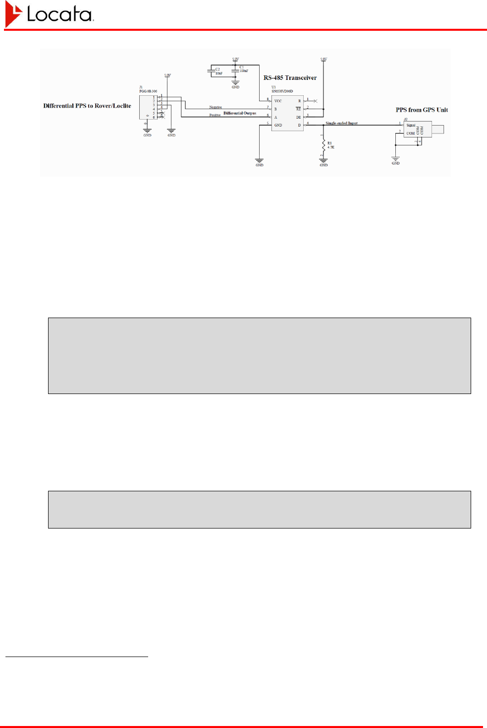
recommends using the adapter shown in Figure 8, “recommended single-ended to
differential conversion circuit” on page 37.
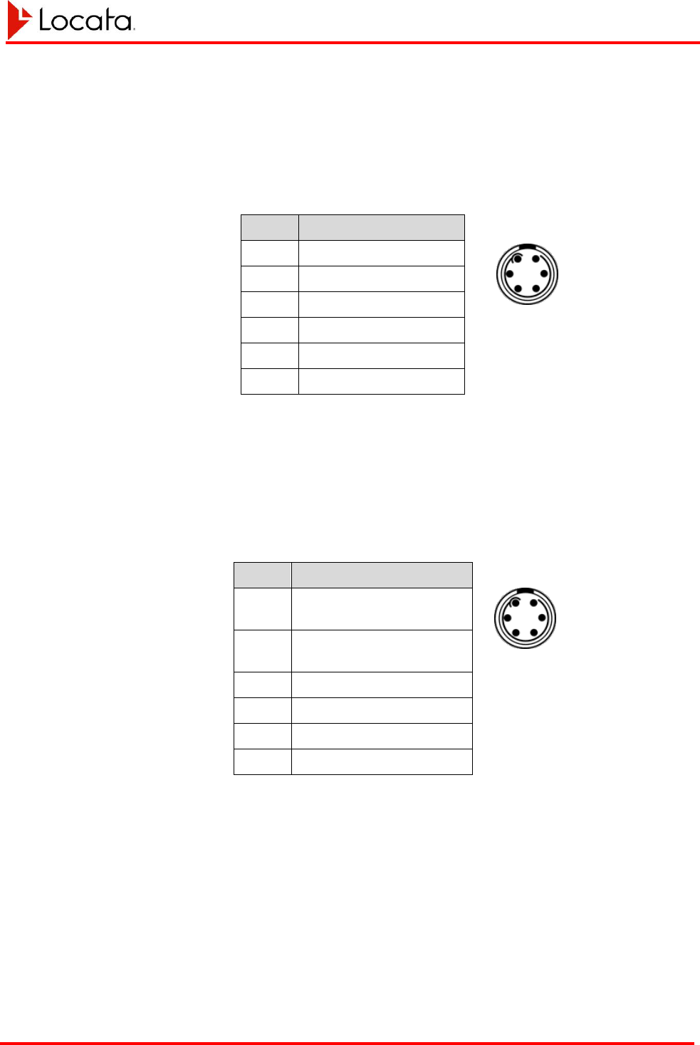
You can access these ports using a LEMO 6-pin connector, part number FGG.0B.306.
Each Auxiliary port can supply up to 0.8 Amps of current at 5 volts.
Chapter 2
LocataLite Characteristics LocataLite User's Manual
Locata-LocataLite-UserManual v8r0
27-May-2014
23
Aux-1
The Aux-1 port presently supports both a one-pulse-per-second timing input (to which
the LocataLite can optionally synchronize) and a 100 microsecond wide one-pulse-per-
second output. This port is wired in accordance with the following table:
Table 6, Aux-1 connector pin assignments
Pin #
Assignment
1
PPS input
2
PPS input (inverted)
3
GND
4
+5v output
5
PPS output
6
PPS output (inverted)
Aux-2
The Aux-2 port presently provides a 1 microsecond wide measurement epoch pulse and
a second 100 microsecond wide one-pulse-per-second output. This port is wired in
accordance with the following table:
Table 7, Aux connector pin assignments
Pin #
Assignment
1
Measurement epoch
output pulse
2
Measurement epoch
output pulse (inverted)
3
GND
4
+5v output
5
PPS output
6
PPS output (inverted)
Chapter 2
LocataLite Characteristics LocataLite User's Manual
Locata-LocataLite-UserManual v8r0
27-May-2014
24
2.5. LED Status Indicators
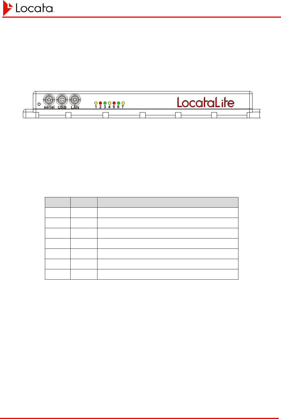
LocataLites have 7 LEDs on the front edge of the device next to the LAN connector.
Figure 6, The LocataLite showing the LEDs
The LEDs are provided to indicate the health and status of the device alerting operators
of error and warning conditions. The role of each LED is shown in Table 8.
Table 8, LED purposes
LED #
Colour
Purpose
1
Yellow
Logging status
2
Red
Network synchronisation status
3
Green
Health & Tracking status
4
Yellow
Position Self-Survey status
5
Red
Application status
6
Green
Device status
7
Yellow
Heartbeat
All LEDs communicate using one or more of the flashing sequences shown in Table 9.

Chapter 2
LocataLite Characteristics LocataLite User's Manual
Locata-LocataLite-UserManual v8r0
27-May-2014
25
Table 9, LED sequences
Sequence
number
Sequence
Name
Flashing
(F)/
Occulting
(O)
Description
1
Off
-
OFF
2
dit
F
80ms ON, 1920ms OFF
3
dah
F
240ms ON, 1760ms OFF
4
dit-dit
F
80ms ON, 240ms OFF, 80ms ON, 1600ms OFF
5
dit-dah
F
80ms ON, 240ms OFF, 240ms ON, 1440ms OFF
6
dah-dit
F
240ms ON, 240ms OFF, 80ms ON, 1440ms OFF
7
dah-dah
F
240ms ON, 240ms OFF, 240ms ON, 1280ms OFF
8
dit-dit-dit
F
80ms ON, 240ms OFF, 80ms ON, 240ms OFF,
80ms ON, 1280ms OFF
9
dit-dit-dah
F
80ms ON, 240ms OFF, 80ms ON, 240ms OFF,
240ms ON, 1120ms OFF
10
occulting
dah
O
240ms OFF, 1760ms ON
11
occulting
dah-dah
O
240ms OFF, 240ms ON, 240ms OFF, 1280ms ON
12
2Hz flashing
F
240ms ON,260ms OFF
13
5Hz flashing
F
100ms ON, 100ms OFF
14
On
-
ON
The typical steady state operating condition for all LEDs is either solid OFF or solid
ON, with the exception of LED 7 – Heartbeat which briefly occults every two seconds.
Flashing sequences on the other LEDs typically indicate a warning, fault or non-steady
state operating condition that may require attention.
Chapter 2
LocataLite Characteristics LocataLite User's Manual
Locata-LocataLite-UserManual v8r0
27-May-2014
26
2.5.1. LED 1 – Logging Status
LED 1 indicates whether the receiver is logging to memory, and if so, the memory
status.
Table 10, LED 1, logging status
State
LED Flashing
Sequence
State Description
LED 1 (yellow)
Logging disabled
OFF
Logging to internal memory is disabled
Logging disabled
(Disk > 80% full)
dah
Logging to internal memory is disabled and internal memory
is nearly full
Logging enabled
(Disk > 80% full)
occulting dah
Logging to internal memory is enabled and internal memory
is nearly full
Warning – Disk full
5Hz flashing
Internal memory is full, logging cannot be enabled
Logging Enabled
ON
Logging to internal memory is enabled
2.5.2. LED 2 – Network Synchronization
LED 2 indicates how well the device is synchronized to the network’s time and
frequency.
Table 11, LED 2, network synchronization status
State
LED Flashing
Sequence
State Description
LED 2 (red)
Not Sync’d to Network
Time
OFF
The LocataLite is not synchronised to network time.
When LED 2 is OFF this implies that the device is the network
MASTER.
Coarse alignment
dah
The LocataLite is synchronised to within 1µs of network time
Fine alignment
dah-dah
The LocataLite is synchronised to within 100ns of network time
High phase event
5Hz Flashing
The LocataLite has experienced a high phase event and dropped
briefly out of TimeLoc
Synced to Network
ON
The LocataLite is synchronised to the network (i.e. TimeLoc)
Chapter 2
LocataLite Characteristics LocataLite User's Manual
Locata-LocataLite-UserManual v8r0
27-May-2014
27
2.5.3. LED 3 – Health and Tracking Status
LED 3 shows the tracking status of the device.
Table 12, LED 3, health & tracking status
State
LED Flashing
Sequence
State Description
LED 3 (green)
No channels allocated
OFF
No channels have been allocated for acquisition or tracking
Attempting acquisition
dit
The device is attempting to acquire signals
1+ signals tracked
dah
The device is tracking one or more signals
Acquired reference
dah-dit
The device has acquired a TimeLoc reference signal
Acquired self
dah-dah
The device has acquired itself for TimeLoc purposes
Broadcasting bad health
5Hz flashing
The device has acquired signals ok but has bad health
Broadcasting good health
ON
The device has good health
2.5.4. LED 4 – Position Self-Survey Status
LED 4 shows the position self-survey status of the device.
Table 13, LED 4, position self-survey status
State
LED Flashing
Sequence
State Description
LED 4 (yellow)
Self-survey
disabled
OFF
Self-survey is disabled
Initial survey in
progress
dit-dit
Self-survey is enabled and the initial survey is in progress. Position
currently unknown
Full survey in
progress
dit-dah
Self-survey is enabled and the initial survey is complete. Full self-survey in
progress.
Movement detected
5Hz flashing
Self-survey is enabled and movement has been detected.
On-going
monitoring
ON
Self-survey is enabled and the full survey is complete. On-going
monitoring for movement is in progress.
Chapter 2
LocataLite Characteristics LocataLite User's Manual
Locata-LocataLite-UserManual v8r0
27-May-2014
28
2.5.5. LED 5 – Application Status
The following table defines the behaviour for LED 5. This LED indicates warnings and
error conditions present in the application. The LED can only display one error at a
time. If multiple errors are present in the system, the LED will only report the highest
priority condition. The priorities listed are 1 (highest) to 10 (lowest).
Table 14, LED 5, application warnings and errors
State
LED Flashing Sequence
Priority
State Description
LED 5 (red)
No warnings or errors
OFF
–
No errors or warnings are currently active
Error – Config file missing
5Hz Flashing
1
No config.txt file could be found
Error – Invalid config parameter
2Hz Flashing
2
An invalid parameter was found in the
config.txt file
Error – No DHCP Server
dit-dit-dit
3
Ethernet connected but no DHCP server
could be found.
Error – AGC initialisation failure
dit-dit-dah
4
Failed to initialise AGC hardware component
Warning – Ext Time Missing
dah-dit
5
External time source could not be detected
(serial message from GPS is missing)
Warning – Ext Time Bad
dah-dah
6
External time quality was bad (in serial
message from GPS)
Warning – Ext PPS Missing
dit
7
External PPS could not be detected
Warning – Ext PPS Bad
dah
8
External PPS quality was bad
Warning – Ext Position Missing
dit-dit
9
External position source could not be
detected (serial message from GPS is
missing)
Warning – Ext Position Bad
dit-dah
10
External position quality was bad (in serial
message from GPS)
Boot in progress
ON
–
The system is performing its boot sequence

Chapter 2
LocataLite Characteristics LocataLite User's Manual
Locata-LocataLite-UserManual v8r0
27-May-2014
29
2.5.6. LED 6 – Device Status
LED 6 provides warning and error information about the system health and status. Only
one warning or error may be displayed at a time. If multiple warnings or errors are
present in the system only the highest priority condition will be reported. The priorities
listed are 1 (highest) to 10 (lowest).
Table 15, LED 6, device status
State
LED Flashing
Sequence
Priority
State Description
LED 6 (green)
Device is a SLAVE or
ROVER
OFF
–
Standard operating condition (SLAVE LocataLite and
Rover)
Device is a MASTER
ON
–
Standard operating condition (MASTER LocataLite)
Low Voltage
dit
–
Insufficient or low voltage to start up (all other LEDs are off)
System Boot Sequence
Single ON
flash.
Duration of
pulse varies
–
The system is progressing through its boot sequence.
The longer the ON period the further through the process.
Turns OFF and starts LED7 once the CPU is started.
Error – over voltage
dit-dah
1
High voltage has been detected on the supply rail
Error – over
temperature
dit-dit-dah
2
The device is over its maximum operating temperature
System will reset if the temperature reaches its extreme
value.
Error – under
temperature
dit-dit-dit
3
The device is under its minimum operating temperature
Error – clock
dah-dit
4
The clock reference is not operating, or the external
frequency reference source has been lost
(not currently implemented)
Error – system failure
5Hz flashing
5
Failure of the system (DDS, FPGA, watchdog failure,
system upgrade failure or immediate maintenance required)
Error – failsafe mode
2Hz flashing
6
The system needs to be reprogrammed
Error – system
maintenance required
dit-dit
7
Maintenance required at earliest convenience. System
working with diminished stability and functionality
Chapter 2
LocataLite Characteristics LocataLite User's Manual
Locata-LocataLite-UserManual v8r0
27-May-2014
30
2.5.7. LED 7 – Heartbeat Indication
This LED provides a system heartbeat.
Table 16, LED 7, heartbeat indications
State
LED Flashing
Sequence
State Description
LED 7 (yellow)
Error – crash
OFF
System Boot Sequence (at power up), or Fatal System Error (crash)
once running
Error – crash
ON
Fatal System Error (crash)
Error – system shutdown
2Hz flashing
System has stopped due to failure (voltage or temperature limit
failure). System will attempt to restart in 20 seconds.
Error – internal storage
corruption
5Hz flashing
System has irrecoverable internal storage corruption
Error – system upgrade
failure
dit-dit
System failed to upgrade
Error – application
stopped
dit
The Rover / LocataLite application has stopped responding.
Booting
dit-dah
CPU is booting (or rebooting)
Reprogramming
dit-dit-dit
System is reprogramming
Normal operation
Occulting dah
Standard operating condition

Chapter 3
LocataLite Installation LocataLite User's Manual
Locata-LocataLite-UserManual v8r0
27-May-2014
31
CHAPTER 3 LOCATALITE
INSTALLATION
3.1. Physical Installation
See Reference 2 for recommendations regarding the physical installation of a
LocataLite, including environmental housings, heat sinks, antennas, and power sources.
See also Section Error! Reference source not found. and its subsections in this manual
for Regulatory Information, FCC Guidelines for Devices Containing a Transmitter
Module, and External Antenna Integration. This document assumes that the LocataLite
has been installed in accordance with this reference.
3.2. Network Configuration
See Reference 2 for recommendations for installing a network of LocataLites.
3.3. LocataLite Configuration File
A configuration file resident on the LocataLite’s internal flash memory contains the
parameters needed to configure the LocataLite for operation. The file is located in the
root ftp directory. The file is named “config.txt” by default but can be renamed by
adding a prefix so long as it continues to match the pattern “*config.txt”.
A wide range of configuration parameters are available using this file. Documentation
describing each parameter is provided within the file itself, a copy of which is provided
in Appendix B. The file can be modified using any standard PC text editor then copied
back to the device via FTP.
Refer to Section 5.2 for troubleshooting configuration file issues.

Chapter 3
LocataLite Installation LocataLite User's Manual
Locata-LocataLite-UserManual v8r0
27-May-2014
32
3.4. Communications Interface Configuration
3.4.1. Ethernet Interface
The LocataLite provides an Ethernet interface via the LAN port. This interface may be
used to connect to the LocataLite using the standard File Transfer Protocol (FTP) or the
Locata Binary Messaging Protocol (LBMP).
It is highly recommended that an Ethernet connection be available to LocataLites as this
simplifies system configuration, software upgrades, and general operations. Note that
this connection requires a shielded cable as per Figure 5.
The following 5 properties define the Ethernet configuration:
1. IP mode, as either DHCP mode or static IP mode,
2. IPv4 address, when in static IP mode,
3. IPv4 net mask, when in static IP mode,
4. Default gateway address, and
5. Device name (hostname).
Ethernet Configuration via Config Files
Ethernet configuration parameters (aside from hostname) are stored in a dedicated
configuration file which lives in the root FTP directory. The file is named
“ethernet_config.txt” by default but can be renamed by adding a prefix such
that it still matches the pattern “*ethernet_config.txt”.
The following is an example of the file contents required to set the LocataLite into
DHCP mode.
# Ethernet configuration: DHCP
iface eth0 inet auto

Chapter 3
LocataLite Installation LocataLite User's Manual
Locata-LocataLite-UserManual v8r0
27-May-2014
33
The following is an example of the contents of an ethernet_config.txt file
required to set the LocataLite into static IP mode with an IPv4 address of 192.168.1.111.
# Ethernet configuration: static
iface eth0 inet static
address 192.168.1.111
netmask 255.255.255.0
gateway 192.168.1.1
Users can query or change the Ethernet configuration using the FTP interface, the serial
ports and the Ethernet port itself via LBMP commands. See Appendix Afor details on
how to do this.
Device Name
The device name (or hostname) is an identifier for the LocataLite. Users can set this
property in the hostname.txt file which is located in the FTP root directory. The
file contains ASCII text specifying the desired hostname. The contents of the file must
adhere to the following rules:
1. contain 1 to 63 characters
2. use only the characters ‘a’ to ‘z’ (hostname is case insensitive), ‘0’ to ‘9’, ‘_’, or
‘-‘, and
3. start with one of the characters ‘a’ to ‘z’
Ethernet Configuration via Communication Protocols
An alternate method for Ethernet configuration is by using communication protocols.
Two protocols provide support for this purpose, binary LBMP and ASCII NMEA, and
allow users to query existing and set new Ethernet configurations. This alternate means
of setting an Ethernet configuration is particularly useful where the user does not know
or has corrupted the existing configuration.
For serial ports running the LBMP protocol the LBMP query (0xC001) and
configuration (0xB002) commands are provided. See Reference 4 for complete LBMP
message definitions. The NMEA $GPLOC,ETH message/command can be used to set
Ethernet configurations on serial ports not running the LBMP protocol. See Appendix
A.2.1 for details.
When setting the Ethernet configuration using a serial connection changes will typically
take effect within a few seconds. Any existing open FTP or LBMP socket sessions will
be terminated when the Ethernet configuration is changed.

Chapter 3
LocataLite Installation LocataLite User's Manual
Locata-LocataLite-UserManual v8r0
27-May-2014
34
Default Configuration
By default Locata ships the LocataLite with a fixed static IP address and netmask.
These are:
# Ethernet configuration: static
iface eth0 inet static
address 192.168.1.111
netmask 255.255.255.0
gateway 192.168.1.1
By default a LocataLite has the hostname locata_tx. If no hostname file is present
the system will default to locata_tx.
3.4.2. COM Port Interface
You can connect external devices to the LocataLite using the serial COM ports. A
portion of the config.txt file designates what types of serial ports are enabled and
which ports they use. Users must select the communication baud rate using the
COMPORT_1_BAUD and COMPORT_2_BAUD configuration file parameters (in
config.txt), and use the COMPORT_1 and COMPORT_2 parameters to set the type
of interface to be used over each of the com ports. Both NMEA and LBMP interfaces
are supported:
NMEA Protocol
The NMEA interface sends both standard and proprietary ASCII sentences following the
NMEA-0183 format. See Appendix A for a detailed description of each of the
recognized NMEA sentences used by the Rover.
Locata Binary Message Protocol
The proprietary Locata Binary Messaging Protocol (LBMP) provides users with much
more information than NMEA messages can accommodate. Locata does not provide
commercial software for decoding and displaying LBMP content. See Reference 4 for a
detailed description of the LBMP.
Note that users must not allocate a single protocol to multiple COM ports.

Chapter 3
LocataLite Installation LocataLite User's Manual
Locata-LocataLite-UserManual v8r0
27-May-2014
35
3.5. Determining the Current Configuration
On boot the device will output basic configuration information in a fixed manner
regardless of specific configuration settings. This feature ensures that users are able to
determine the communications interface configuration if previously unknown, and use
this to access the device for reconfiguration and operation.
At boot the device will display a welcome message including the following basic
configuration information:
Device type
Device name
System version
COMM port 1 configuration
COMM port 2 configuration
Ethernet port (IP) configuration
The information is initially output from both serial ports at a fixed baud rate of 115,200
baud regardless of the configuration settings. Where a serial port has been configured
using a different baud rate the information will be output a second time using the
configured rate.
By default Locata ships the LocataLite with a fixed static IP address and netmask.
These are:
# Ethernet configuration: static
iface eth0 inet static
address 192.168.1.111
netmask 255.255.255.0
gateway 192.168.1.1
Chapter 3
LocataLite Installation LocataLite User's Manual
Locata-LocataLite-UserManual v8r0
27-May-2014
36
3.6. Optional LocataLite Configurations
3.6.1. GPS Synchronization (“GPS Sync”)
You can synchronize the Master LocataLite’s timing to a one-pulse-per-second timing
source, whether GPS or another source. This will cause the entire network to operate
synchronized to this time source.
The LocataLite receives PPS timing signal using Auxiliary port 1 and the date, time and
PPS quality information using one of the COM ports.
The LocataLite supports the following clock sources for the purpose of synchronizing to
GPS time and frequency:
1. SigNav uTevo GPS receiver;
2. Any Leica/NovAtel GPS receiver supporting the ‘#TIMEA’ message;
3. Symmetricom TSC 4400 (see reference 8 for more information on this device);
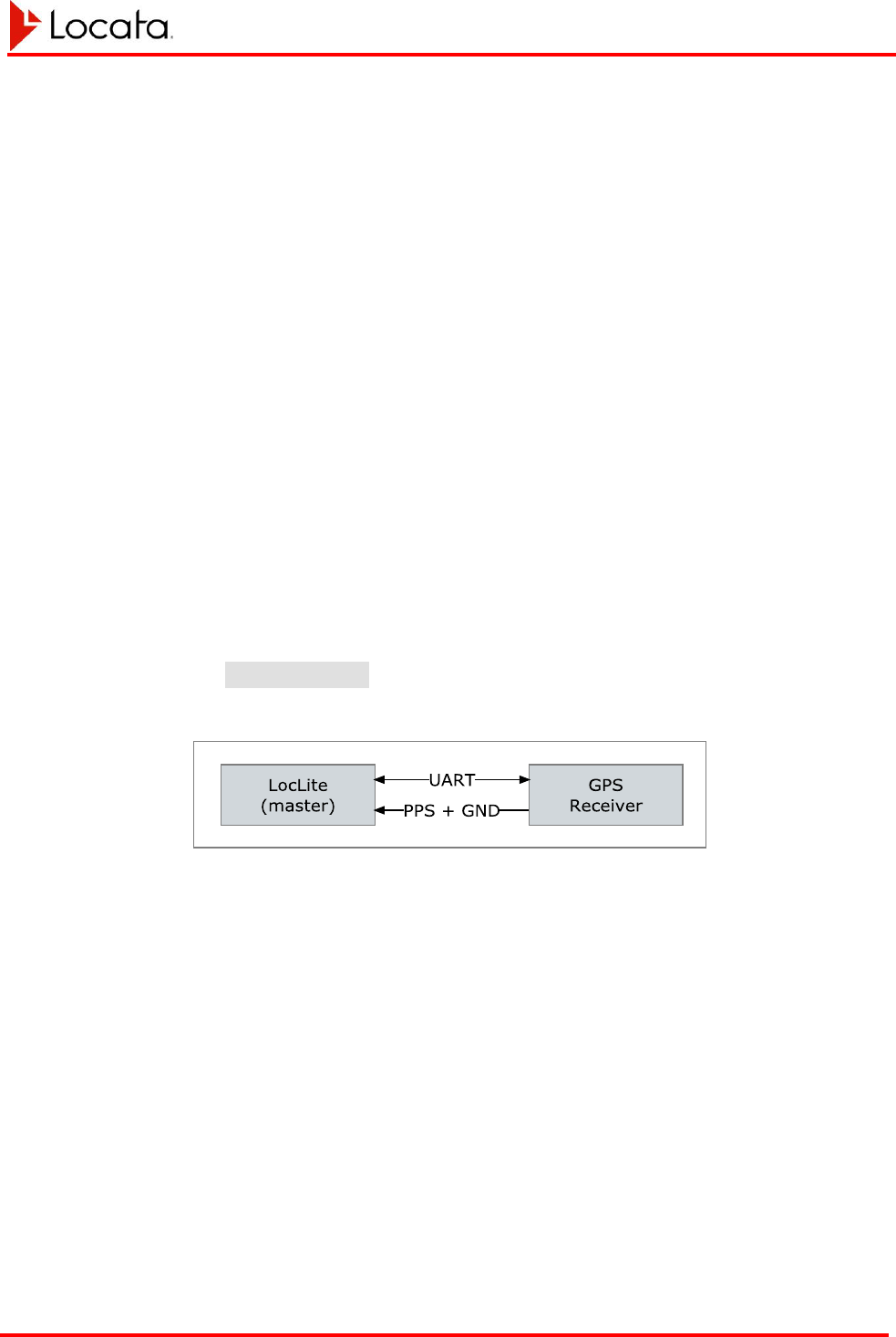
You should connect the GPS receiver to the LocataLite using whichever COM port has
been allocated as IO_PORT_GPS in the config.txt file. Connect the PPS signal
from the GPS receiver to the LocataLite using port A1.
Figure 7, GPS Sync connection
Configure the GPS receiver to automatically output a serial message giving the date,
time and validity of the PPS for transmission to the COM port in use. This message
should be output at the 1Hz rate preferably within 200ms of the pulse.
Many PPS sources output a 0–5V active high pulse. If this is the case the PPS must be
converted to a differential signal for input to the Aux 1 port using an in-line converter
designed per the following circuit.
Chapter 3
LocataLite Installation LocataLite User's Manual
Locata-LocataLite-UserManual v8r0
27-May-2014
37
Figure 8, recommended single-ended to differential conversion circuit
Using the SigNav uTevo for GPS Sync
The following configurations apply when using the uTevo GPS timing source.
LocataLite Configuration
Configure the following options in the config.txt file.
Device_Type = MASTER_WITH_GPS_SYNC;
COMPORT#
3
= IO_PORT_GPS;
COMPORT_#_BAUD3 = 115200B;
GPS_Receiver_Type = uTevo;
GPS Setup/Configuration
The default internal uTevo configuration is appropriate for GPS sync.
If necessary you can issue a factory reset command (clear & reset) to the uTevo to return
it to its default configuration. This command is:
$PSGNC,CAR\r\n
Serial Message
The NMEA style SSR message provided by the uTevo supplies the time, date and PPS
validity information which the master LocataLite uses. You can find the definition of
the SSR message in Appendix A.
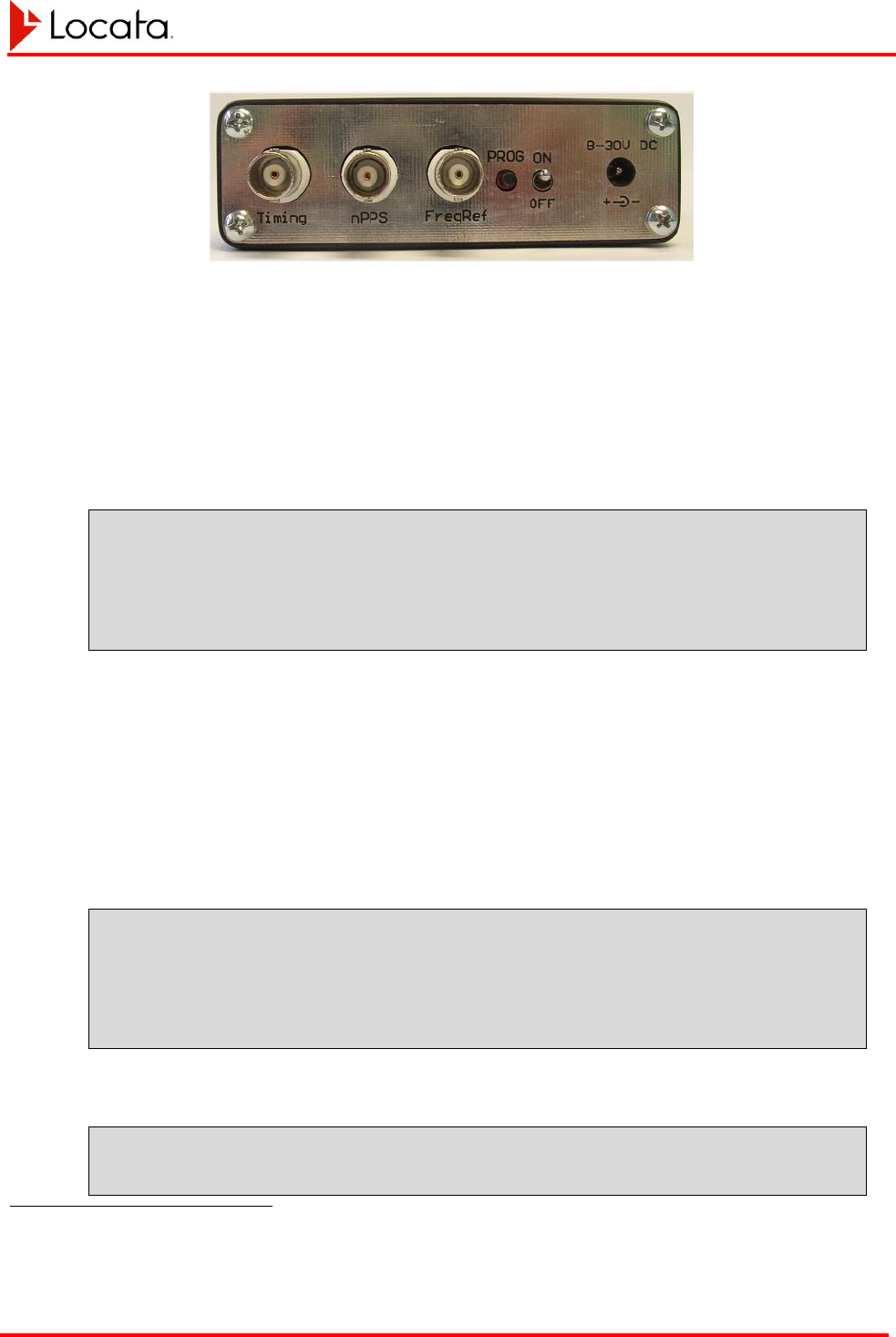
PPS
The “Timing” port shown in the following image supplies the uTevo PPS output.
3
This may be COMPORT1 or COMPORT2 as appropriate.
Chapter 3
LocataLite Installation LocataLite User's Manual
Locata-LocataLite-UserManual v8r0
27-May-2014
38
Figure 9, uTevo panel
Using the Symmetricom TSC-4400 for GPS Sync
The following configurations apply when using the Symmetricom GPS timing source.
LocataLite Configuration
Configure the following options in the config.txt file.
Device_Type = MASTER_WITH_GPS_SYNC;
COMPORT#
4
= IO_PORT_GPS;
COMPORT_#_BAUD4 = 38400B;
GPS_Receiver_Type = TSC4400;
GPS Setup/Configuration
The TSC4400 has a number of configuration files that need to be configured
appropriately for operation with the LocataLite. For information on how to change the
configuration files please refer to Reference 9. In the following three files, set the values
provided here:
novalog.nml
LOGDATA = 15
LOGFILES = 100
CARRIER_SMOOTHING = 60
COMMAND = “log GPGSV ontime 1”
realtime.nml
BAUD = 38400
4
This may be COMPORT1 or COMPORT2 as appropriate.

Chapter 3
LocataLite Installation LocataLite User's Manual
Locata-LocataLite-UserManual v8r0
27-May-2014
39
COMMAND = “log GPGSV ontime 1”
COMMAND = “log timea ontime 1”
startup.cfg
ANTENNA_POSITION = AUTO
AUTO_POS_PERIOD = 12
ANTENNA_DELAY = 2.688e-9
MAS_ANGLE = 10
REFERENCE = INTERNAL
EXTERNAL_REF = NONE
STEER_MODE = CLOCK
OUTPUT_FREQ = 10.0
COM_MODE = REALTIME
REALTIME_IP_LOGGING = TRUE
NOVALOG_CFG = /mod/lim/novalog.nml
REALTIME_CFG = /mod/lim/realtime.nml
TIMESCALE_CFG = /mod/lim/internalRb.cfg
ERROR_LOG = /dev/null
COMPRESS_LOGS = TRUE
Serial Message
The #TIMEA message provided by the TSC 4400 supplies the time, date and PPS
validity information which the master LocataLite uses.
You can find the definition of the #TIMEA message in Reference 10.
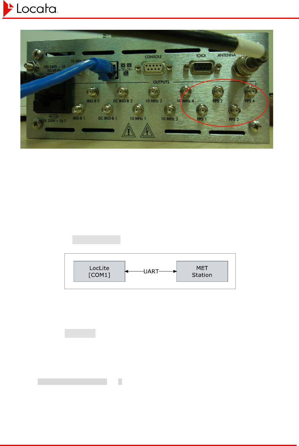
PPS
The TSC 4400 PPS output can come from the any of the 4 PPS ports shown in the
following image.
Chapter 3
LocataLite Installation LocataLite User's Manual
Locata-LocataLite-UserManual v8r0
27-May-2014
40
Figure 10, TSC-4400 rear panel
3.6.2. Interfacing a Meteorological Station to a
LocataLite
The LocataNet supports the Vaisala PTU300 MET station. See reference 6 for more
details on this device.
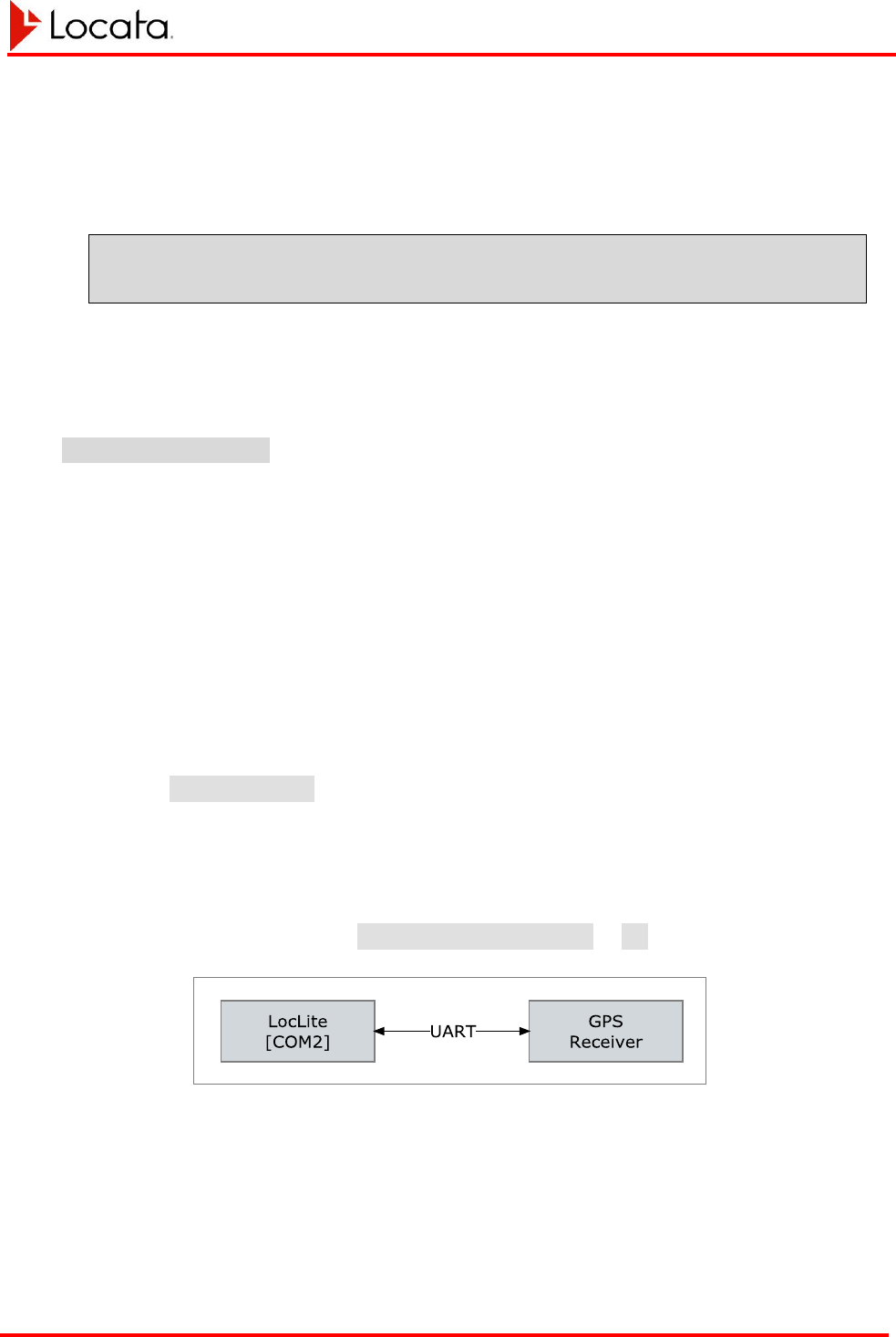
The MET station should be connected to the LocataLite via whichever serial port has
been allocated as IO_PORT_MET in the config.txt file.
Figure 11, LocataLite interconnection with a MET station
The MET station should be configured for serial communications at the same baud rate
as specified for the serial port it is connected to as specified in the config.txt file.
A baud rate of 115,200 baud is recommended. See the Vaisala user manual (ref 6) for
configuration details.
The LocataLite can be configured to communicate with the attached MET station in
three different ways via the config.txt file.
met_station_polling = 2;
The default value of ‘2’ instructs the LocataLite to configure the MET station once,
every time the LocataLite starts up, to automatically generate the required information at
Chapter 3
LocataLite Installation LocataLite User's Manual
Locata-LocataLite-UserManual v8r0
27-May-2014
41
a rate of 1Hz. No further communication from the LocataLite is then made to the MET
station.
The value of ‘1’ instructs the LocataLite to poll the MET station at 1Hz to request data
using the command:
*0100P9\r\n
The value of ‘0’ instructs the LocataLite to not communicate with the MET station at all.
This may mean that the MET station will not contribute any useful information if it has
not previously been configured by a LocataLite using the value of ‘2’ for
met_station_polling. This option is useful only in situations where communication
between the LocataLite and MET station can only be unidirectional, but does require
that the MET station have been previously configured and that configuration saved.
3.6.3. Setting up LocataLite Self-Survey
You can install a Leica RTK GPS survey receiver at a LocataLite site for accurate,
automatic LocataLite antenna surveys. This receiver provides its own location data to
the LocataLite. The LocataLite then calculates a surveyed position for its antennas
using known offsets from the GPS receiver antenna. The survey GPS receiver uses one
of the LocataLite’s two serial ports to provide position data to the LocataLite.
Connect the GPS receiver to the LocataLite using whichever COM port has been
allocated as IO_PORT_GPS in the config.txt file.
Configure the COM port speed in the LocataLite’s config.txt file. Configure the
GPS receiver to match the LocataLite COM port speed prior to connecting it to the
LocataLite.
Set the config.txt parameter SelfSurvey_enabled to ON.
Figure 12, LocataLite-GPS interconnection for self-survey
LocataLites with self-survey enabled will send a request over the allocated COM port at
boot to schedule TPV message output at 1Hz from the attached GPS receiver. The
LocataLite uses this TPV data to determine its antenna positions.
Chapter 3
LocataLite Installation LocataLite User's Manual
Locata-LocataLite-UserManual v8r0
27-May-2014
42
You can use any Leica RTK GPS receiver that supports the TPV output schedulable via
the $PLEIQ,TPV message to support self-survey.
A LocataLite with self-survey enabled will output the TPV scheduling request once
every 10 seconds until it receives a TPV response. This allows the LocataLite and GPS
receiver to power up in any order.
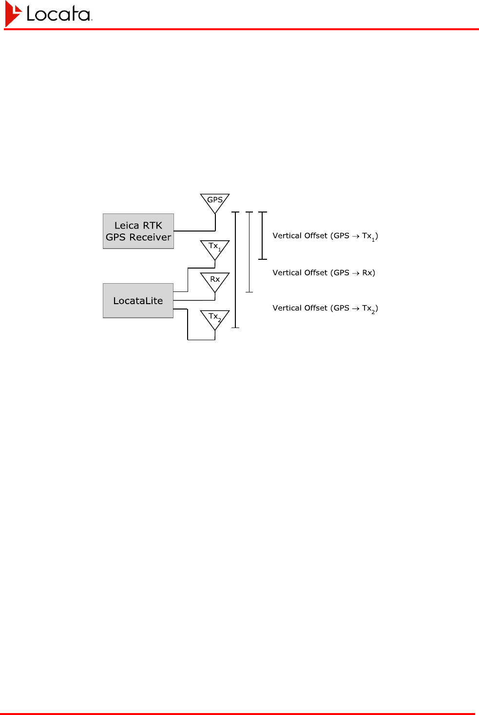
Be sure to position the GPS receiver antenna on a vertical line with the LocataLite
antennas as shown in the figure below. There should be no horizontal offset between the
four antennas. The vertical offsets shown in the figure are all positive.
Figure 13, Permissible arrangement of antennas when self-surveying

Chapter 3
LocataLite Installation LocataLite User's Manual
Locata-LocataLite-UserManual v8r0
27-May-2014
43
Self-Survey Operation
The GPS self-survey feature performs the following sequence of events at boot.
1. Check for previously saved position survey result
5
;
2. Use incoming GPS TPV data to perform a short initial survey (~2 minutes);
3. Allow the LocataLite to perform TimeLoc and become active;
4. Continue using incoming TPV data to perform a full survey (~12 hours);
5. Continue using incoming TPV data to detect antenna movement (flag error
condition if movement detected);
Defining LocataLite Response to Loss of GPS Position Data
The behavior of self-survey may be customized using several config.txt
parameters. These parameters, listed below, define whether GPS position data is
required during the various stages of self-survey and what the response of the LocataLite
should be if GPS position data is not available.
SelfSurvey_GPS_rqd_to_load_nv_posn
YES
At boot any previous survey result stored in non-volatile memory must be
validated by comparing it against a GPS position before it can be used.
NO
At boot any previous survey result stored in non-volatile memory can be used
even if GPS position data is unavailable.
SelfSurvey_GPS_rqd_during_full_survey
YES
During the full survey the LocataLite will broadcast that it has bad health if the
GPS is unavailable.
NO
During the full survey the LocataLite will continue to broadcast good health even
if the GPS is unavailable.
SelfSurvey_GPS_rqd_during_monitoring
YES
During on-going position monitoring the LocataLite will broadcast that it has bad
health if the GPS is unavailable.
NO
During on-going position monitoring the LocataLite will continue to broadcast
good health if the GPS is unavailable
5
If a previously saved position survey result was detected the LocataLite will attempt to verify that the position using a
small number of incoming TPV messages. If the LocataLite does not appear to have moved the saved position will be
trusted and the LocataLite will skip step 2.

Chapter 3
LocataLite Installation LocataLite User's Manual
Locata-LocataLite-UserManual v8r0
27-May-2014
44
SelfSurvey_movement_asserts_bad_health
YES
If the LocataLite detects movement it will broadcast bad health
NO
If the LocataLite detects movement it will continue to broadcast good health
Recommended Configuration
The recommended configuration depends on the availability of GPS, how likely a
movement event is and what sort of network monitoring is being performed.
If there is little risk of a LocataLite moving after the full survey has been performed then
most of the above configuration options can be switched off. This will allow a single
full survey result to be used irrespective of whether GPS is continuously available or
not.
If there is an appreciable risk that the LocataLite may move during operation then
ideally the ‘GPS_rqd’ options should be enabled.
GPS Self-Survey Installation Procedure
1. Mount all four antennas phase centers aligned vertically with each other and with
the GPS antenna on top.
2. Measure vertical offsets between the phase center of the GPS antenna, and the
phase centers of the Locata antennas using a tape measure
3. Enter these offsets into the LocataLite’s config.txt file.
4. Enable GPS survey in the config.txt file.
5. Configure GPS to output 115200 baud rate.
6. Connect GPS to the COM port designed ‘IO_PORT_GPS using a null modem
cable.
7. Power up the LocataLite and GPS receiver.

Chapter 4
LocataLite Operation LocataLite User's Manual
Locata-LocataLite-UserManual v8r0
27-May-2014
45
CHAPTER 4 LOCATALITE OPERATION
LocataLites are self-regulating, and do not require any attention during operations once
transmissions begin. Operation may continue for months without the LocataLites
requiring attention. The areas where user action may be required are: starting and
ceasing operations, accessing log files, configuration and software upgrades. These are
all covered in the following sections.
4.1. Starting Operations
Before starting operations, ensure that a LocataLite’s transmit and receive antennas are
properly connected to their respective LocataLite outputs. Peripherals such as GPS
receivers or MET stations should also be connected.
LocataLites within a network may be started in any order. Slave LocataLites (so
configured in config.txt) will look for a Master or reference signal to acquire, then
synchronizing to before beginning transmission. If the Slave sees no reference signal, it
will continue the search for one, and remain in a non-radiating, non-synchronized state
until it succeeds.
The availability of meteorological data does not affect transmissions from LocataLites to
which they may be attached, only the data reported in the navigation message overlay
regarding the meteorological data seen.
The availability of GPS data may affect transmissions from a LocataLite configured to
perform a self-survey depending on the parameters defined in config.txt.
Once power has been applied, the LEDs on the front edge of the LocataLite case will
show the status of the LocataLite as it progresses through its startup sequence (see
section 2.4 on page 17 for details of the LED flashing scheme). In particular, once LED
3 switches ON solid the LocataLite is broadcasting with good health. The LBMP
messages may also be queried to determine the health and status of the LocataLite.
There is no need for operator action once power has been applied unless config.txt
parameters need to be changed. If this is the case the operator will need to apply power,
wait for the LocataLite to boot, make the changes then restart or reboot the LocataLite.
4.1.1. Master Startup
You may start the Master at any time. Simply apply power to the LocataLite to do so.
Once the Master is transmitting, any Slave LocataLites in the network that are powered
on will be able to acquire, track and TimeLoc to the Master signals.

Chapter 4
LocataLite Operation LocataLite User's Manual
Locata-LocataLite-UserManual v8r0
27-May-2014
46
Masters that are configured to synchronize to GPS time will not transmit until they have
good GPS timing data and have synchronized to the one-pulse-per-second timing pulses
furnished by the GPS receiver. During the synchronization process the Master
LocataLite will being broadcasting, however it will broadcast at low power and with bad
health in its NAV data until the synchronization process completes. If GPS timing is lost
after the LocataLite has achieved full synchronization, the LocataLite will continue
operation however it will no longer report that it is synchronized to an external time
source.
4.1.2. Slave Startup
Slave LocataLites may be started at any time however they will not broadcast until they
have acquired a reference signal (typically the network Master).
The Slave LocataLite will remain in a TimeLoc search mode until it receives a Master or
other TimeLoc’d Slave’s signal. It will then proceed to acquire the signal and TimeLoc
to it. Once the Slave begins the TimeLoc synchronization process, it will transmit a
weaker signal adequate for its own receiver to detect, to use to pull in the
synchronization. Once the Slave achieves synchronization, it will ramp up its transmit
power to its operational level. The entire process from power on to signal transmission
is handled automatically and ordinarily requires no operator intervention.
4.2. Ceasing Operations
You can use the presence or absence of Master LocataLite signal within the network to
control the transmissions of all Slave LocataLites within the network. If you stop the
Master’s transmissions, the Slaves will all immediately cease transmission within
seconds and revert to a search mode until the Master reactivates. Therefore you may
stop all transmitted signals within the network at once by powering off the Master
LocataLite for the network or sharply reducing its transmitted power. This provides a
rapid network stop capability. Note that this stops all Slave transmissions, but does not
power off the Slave LocataLites, which will continue to consume their nominal DC
power until powered off by other means.
You may also deactivate any LocataLite simply by removing DC power from it at any
time. For example, LocataLites may be connected to power through a timer, such as
those used to control lights by time of day. When the timer removes power, operation
will cease. When the timer again restores power, LocataLite operation will begin again,
assuming its reference LocataLite is up and radiating.
If desired, you may include a remote means for controlling DC power to the LocataLites
in Locata network deployments. An example would be using a wireline or wireless
modem to control a power relay, configured to provide power to the LocataLite when
activated by remote command. You can also use such a modem for accessing the
LocataLite serial or Ethernet interfaces for additional device control and monitoring.
Chapter 4
LocataLite Operation LocataLite User's Manual
Locata-LocataLite-UserManual v8r0
27-May-2014
47
This will give you complete remote control of each LocataLite installation, greatly
simplifying the operation, control, and monitoring of widely dispersed networks.
4.3. Accessing the LocataLite via FTP
The LocataLite runs an FTP server. With an Ethernet connection to the LocataLite users
may use an FTP client to initiate an FTP session with the LocataLite. The IP address of
the LocataLite must be known to start an FTP session. The LocataLite supports
anonymous logins so no username or password is required.
The FTP interface provides several capabilities including:
1. upload new software
2. upload/download LocataLite application configuration file (*config.txt)
3. upload/download Ethernet configuration file (*ethernet_config.txt)
4. upload/download device name file (hostname.txt)
5. check software version information
6. download or delete log files
7. issue basic commands (reboot, upgrade software, restart)
Once an FTP connection has been established the user will have access to the FTP root
directory. This directory resides in part of the LocataLite’s non-volatile memory. The
following table defines the FTP directory structure and available content.
Directory
File
Description
/
FTP root directory
*config.txt
LocataLite application configuration file.
*ethernet_config.txt
Ethernet configuration file
hostname.txt
Hostname configuration file
iode.bin
IODE counter
*_upgrade.tar.gz
Software upgrade file (file is removed once used)
/logs
Logs sub-directory
log#.lbf
Auto-incrementing numbered LBMP log files
error_log.txt
Any system errors will be reported here
/version
Version information sub-directory
software_name.txt
Contains the name of the last *_upgrade.tar.gz file

Chapter 4
LocataLite Operation LocataLite User's Manual
Locata-LocataLite-UserManual v8r0
27-May-2014
48
sw_version.txt
Contains software version information
fpga_header.txt
Contains FPGA version information
The LocataLite FTP server supports the usual commands: put, get, delete,
cd, ls, pwd and quit.
FTP sessions do not persist over system reboots however they will persist across an
application restart.
4.4. Issuing Commands via FTP
The LocataLite recognizes several specifically named files as command requests when
they are put into the FTP root directory by a user. The files require no content and are
recognized with the .txt extension or without any filename extension.
Available commands by filename and their effects include:
cmd_restart.txt
Restart the LocataLite application. This causes any
config.txt changes to take effect
cmd_upgrade.txt
Initiate a software upgrade provided a suitable
upgrade file is present. This will result in a system
reboot which will also cause any other
configuration file change to take effect.
cmd_ethernet.txt
Apply the current ethernet_config.txt
changes without causing a reboot.
cmd_reboot.txt
Power cycle the LocataLite. This causes all
configuration file changes to take effect. It also
initiates a software upgrade if an upgrade file is
present.
To issue one of these commands start an FTP session with the LocataLite and upload
one of the named files. The LocataLite should respond within two seconds to the
command. As part of responding to the command the LocataLite will delete the
command file.
4.5. Configuring the LocataLite
The LocataLite’s configuration files config.txt, ethernet_config.txt and
hostname.txt reside in the FTP root directory. They can be copied onto or off the
LocataLite using FTP. Any modifications to the files need to be made by copying the

Chapter 4
LocataLite Operation LocataLite User's Manual
Locata-LocataLite-UserManual v8r0
27-May-2014
49
files off the LocataLite onto a PC, editing them there, then copying them back onto the
LocataLite.
Changes to configuration files require a trigger to take effect. All configuration changes
may be triggered by a system power cycle or reboot. Alternatively use the appropriate
FTP command file defined in section 4.4.
4.6. Accessing Log Files
The LocataLite may be configured to log data to internal memory during operation.
This configuration is handled in the config.txt file. The LocataLite may log LBMP
data, ASC data, event and error messages. At present the LocataLite may only log
LBMP or ASC data if those protocols have been allocated to one of the serial ports. In a
future release this restriction will be lifted.
LBMP data is logged to files using the naming convention log#.lbf. The hash mark
represents an incrementing integer for successive log files.
ASC data is logged to files using the naming convention log#.csv. The hash mark
represents an incrementing integer for successive log files.
System events are logged to files using the naming convention event#.log. The
hash mark represents an incrementing integer for successive log files.
Errors are automatically logged to the file error_log.txt. This includes any issues
found during a software upgrade.
All log files can be accessed via FTP to the LocataLite. The files are located in the
/logs subdirectory. Log files can be downloaded or deleted as desired.
It is possible to fill the LocataLite’s internal memory if file logging is enabled for too
long. The internal memory is large enough to log continuously for up to several weeks
depending on which messages are scheduled, at what rates, and how many LocataLites
are present in the network. If the internal memory becomes full LED 1 will flash.
4.7. Upgrading the LocataLite Software
LocataLite software updates take the form of an upgrade file such as
‘v8r0p0_loclite_upgrade.tar.gz’, where the ‘v8r0p0’ reflects the version
number of the software.
Performing a software upgrade requires an Ethernet connection to the LocataLite. Use
FTP to upload the file to the FTP root directory on the LocataLite. Once the file is
uploaded, issue an upgrade command to the LocataLite. This command may be issued

Chapter 4
LocataLite Operation LocataLite User's Manual
Locata-LocataLite-UserManual v8r0
27-May-2014
50
using the FTP cmd_upgrade file or via the LBMP system command message.
Alternatively power cycling the LocataLite will trigger the upgrade process.
The upgrade process can take up to 5 minutes to complete. Once the upgrade process
has completed the LocataLite application will automatically restart. During some of the
upgrade process the LocataLite will disable FTP and LBMP socket connections. The
LEDs will indicate when an upgrade is in progress and when it has completed. For
remote users the ability to create an LBMP socket connection will signify that the
upgrade process has completed.
As a safety measure, if for any reason the LocataLite encounters an error or loses power
while upgrading, it will revert to the version of software in use before the upgrade.
Users can check whether an upgrade has completed successfully by checking the version
information as described in section 4.8.
4.8. Checking Version Information
The LocataLite stores its version information in a directory accessible via FTP. As
defined in section 4.3 the /version directory contains three version files.
Users should check the contents of the software_name.txt file to see which
version of software is running. This file contains the name of the last upgrade file used
to program the LocataLite. This file will typically start with the version string which
takes the form:
vXrYpZ
Where:
o v – version
o r – release
o p – patch
The version string may also be obtained from the LBMP message 0x9002.
4.9. LBMP via TCP
The LocataLite operates two TCP based LBMP servers. With an Ethernet connection to
the LocataLite a user may establish a socket based connection to either or both of these
servers.

Chapter 4
LocataLite Operation LocataLite User's Manual
Locata-LocataLite-UserManual v8r0
27-May-2014
51
The first server listens on port 5012. When a client connects to this port the server
automatically outputs any messages that have been scheduled using the
‘LBMP_schedule_message’ parameters in the config.txt file. This is the same
behavior as a serial port that has been assigned the LBMP protocol.
The second server listens on port 5013. When a client connects to this port it will not
output any message automatically. The server listens for queries or commands from the
client and responds to them.
See the LBMP ICD (see reference 4) for further details of the LBMP protocol.
The LocataLite will accept up to 16 simultaneous connections on each port. The speed
of the connection is limited by the overall speed of the Ethernet connection. An LBMP
connection over Ethernet will typically be faster than one using a serial port.
LBMP socket sessions do not persist between application restarts or LocataLite reboots.
4.10. Serial Communication
The LocataLite has two serial communications ports; both accessible via a single 5-pin
LEMO connector (see Figure 3). These ports are typically used to connect the
LocataLite to peripherals such as GPS receivers and MET stations; however they may
also be used to access measurement and network data, as well as query and set the
Ethernet configuration.
The config.txt file specifies what protocols are active on each COM port as well as
the data rate for each port. See section Error! Reference source not found. on page
Error! Bookmark not defined. for more detail on setting up the serial ports.
Serial protocols include
NONE
No protocol selected for the port
MET
Used when the port is connected to a meteorological station.
GPS
Used when the port is connected to a GPS timing or survey receiver
LBMP
Used for LBMP query and response covering a range of
measurement and network data
NMEA
Used for ASCII data output following standard NMEA conventions
ASC
Proprietary protocol used for voltage and temperature testing
Supported data rates include: 9,600, 19,200, 38,400, 56,400, 115,200, and 230,400
Baud. The higher rates are preferred when feasible.

Chapter 4
LocataLite Operation LocataLite User's Manual
Locata-LocataLite-UserManual v8r0
27-May-2014
52
The serial ports may be used to determine the Ethernet configuration (e.g. IP address) of
the LocataLite. This process is described in section Error! Reference source not
found. on page Error! Bookmark not defined..
4.11. Web Interface
The LocataLite operates a HTTP server which provides a set of simple web pages which
display information derived from the LBMP messages defined in reference [4]. To
access the web interface use a web browser and set the address to,
http://<locatalite_ip_address>
Once on this page click on a link to one of the LBMP messages to display data from a
given message. The web server will generate a static page and populate it with current
data from the selected message. Refreshing the page will trigger a or re-requesting of
data that will then be updated on the page.
Supported web browsers include:
Internet Explorer 9+
Firefox 16+
Chrome 24+

Chapter 5
Troubleshooting LocataLite User's Manual
Locata-LocataLite-UserManual v8r0
27-May-2014
53
CHAPTER 5 TROUBLESHOOTING
For the most part, once the LocataLite and associated equipment are properly configured
and interconnected, operating the LocataLite is simply a matter of turning it on and
letting it initialize and begin operations. The following troubleshooting advice may
however assist in solving issues should they arise.
5.1. General Troubleshooting
The following general advice may assist in troubleshooting operational and performance
issues:
Check the state of the device LEDs for general warnings or error conditions. The
typical steady state operating condition for all LEDs is either solid OFF or solid
ON, with the exception of LED 7 – Heartbeat which briefly occults every two
seconds. Flashing sequences on the other LEDs typically indicate a warning,
fault or non-steady state operating condition that may require attention. See
Section 2.4 for details of LED pattern meanings.
Ensure that all electrical connections to the device are present and secure. Ensure
that the desired communications interfaces have been connected in accordance
with descriptions provided in this manual and that antenna connections are
present.
Ensure the frequency plan configuration of the device matches the rest of the
network.
Ensure the desired LocataLite device type has been selected and that each
LocataLite device is assigned a unique device identifier.
5.2. Device Configuration Troubleshooting
In the event that the config.txt file is missing or contains an error when the
application is started the system will enter an error state where an error report is output
via COM1 at 1Hz with LED 5 flashing to indicate that an error has been encountered. In
this error state users will not be able to establish TCP based LBMP connections to the
device. Users will be able to FTP into the device and check the error_log.txt file
in the /logs directory to determine the source of the problem.

Chapter 5
Troubleshooting LocataLite User's Manual
Locata-LocataLite-UserManual v8r0
27-May-2014
54
5.2.1. Communications Interface Troubleshooting
If the device is not responding to communications requests at all or accepting remote
connections the following steps may be helpful:
Confirm there are no issues with the physical connections to the device
Check that the device configuration file has been configured as expected. Serial
port baud rates, IP configuration, and automatic message output settings are all
user accessible and may be different than expected.
Check that the communications settings being used on the host platform match
the device configuration. If the device is not responsive the settings may have
changed and the Ethernet IP address or serial port baud rate may be incorrect.
Try an alternate interface for communicating with the device. Communication is
possible through either the Ethernet port (TCP/IP) or either serial port. When
using a TCP connection it is possible to interact with the device through a HTTP
connection, FTP session, or though the LBMP protocol via a TCP socket. See
Error! Reference source not found. for details.
It is possible to determine the current device configuration by observing
information output at boot time on the serial ports. This ASCII boot message is
always output at a fixed baud rate and includes the current communications
interface configuration. See Section 3.5 for details.

Chapter 5
Troubleshooting LocataLite User's Manual
Locata-LocataLite-UserManual v8r0
27-May-2014
55
5.3. Troubleshooting the Position Reference GPS
Receiver
1. Check that the serial cable is plugged into the appropriate COM ports on the
LocataLite and GPS receiver.
2. Check that the GPS receiver is outputting TPV messages.
If not, perhaps the GPS receiver was started or connected after the LocataLite had
sent the TPV request message. Restarting the LocataLite after connecting the GPS
receiver may solve this issue.
3. Check that the TPV messages are reporting an RTK solution (solution type 254).
If not, perhaps the GPS receiver is not getting differential correction data from its
reference station. Consult the GPS manufacturer for more help on this issue.
5.4. Troubleshooting the Timing Reference GPS
Receiver
5.4.1. uTevo GPS Receivers
In case of difficulties getting a uTevo GPS receiver time source working, check the
following items:
1. Check that the serial and PPS cables are plugged into the appropriate ports on the
LocataLite and uTevo.
2. Check the behavior of LEDs 3 and 4.
LED 3 indicates the status for GPS synchronization, as shown in Table 12, LED 3,
health & tracking status on page 27. LED 4 will display the particular fault
detected if there exists no other higher priority fault. LED 4 fault codes are shown
in Table 13, LED 4, on page 27. Possible faults include:
External PPS Missing. Serial communication is operating between the uTevo and
the LocataLite, the uTevo has GPS lock, but the LocataLite can't see the PPS.
Most likely the cable connecting the GPS PPS to the LocataLite is incorrectly
installed or faulty.
External PPS Bad. Serial communication is operating between the uTevo and the
LocataLite, but the uTevo receiver has not locked to GPS time itself;

Chapter 5
Troubleshooting LocataLite User's Manual
Locata-LocataLite-UserManual v8r0
27-May-2014
56
External Time Missing. The LocataLite cannot detect a serial connection between
itself and the PPS timing source.
External Time Bad. Serial communication is operating between the uTevo and the
LocataLite, the uTevo has GPS lock, but the LocataLite can't see the PPS. Most
likely the cable connecting the GPS PPS to the LocataLite is incorrectly installed
or faulty.
If the LocataLite LED behavior is difficult to distinguish it is possible to get the same
information from the serial stream of $GPLOC,ASC messages that output from COM1
on the LocataLite [115200 baud, 8 data bits, 1 parity bit, no flow control, null modem
cable]. The second last field of the ASC message before the checksum indicates the GPS
sync error state with the following possible values (matching the error states above):
State 0: no error
State 1: missing serial comms
State 2: bad PPS status
State 3: missing PPS
Connect a computer to the GPS receiver serial feed [115200 baud, 8 data bits, 1 parity
bit, no flow control, null modem cable] and check the SSR report status (which is output
automatically at 1Hz). The Appendix “Message Definitions” contains a definition of the
SSR message.
In particular look at the last 6 fields of the SSR (underlined below). These are the
holdover (1), time/frequency tolerances (4) and error conditions (1). When the uTevo
has a good solution and an accurate PPS output they should read 0,1,1,1,1,0* as shown.
If they read differently then the uTevo is not fully locked to GPS and the LocataLite will
not trust the PPS. This would constitute the "State 2" error cited above.
$PSGNR,SSR,20100721,093159,1,15.0,0,1,0,1,1,1,1,0*CS
If the uTevo is reporting that it does not have GPS lock (as described in point 3 above) it
is possible to send queries to determine which signals are being tracked, which have
downloaded ephemeris data, and whether a position/time solution is being computed.
The following set of commands would be useful. The uTevo communication protocol
(Reference 7) describes the commands and their responses.
$GPGPQ,GSV
$GPGPQ,GGA
$GPGPQ,GSA
$GPGPQ,UNC

Chapter 5
Troubleshooting LocataLite User's Manual
Locata-LocataLite-UserManual v8r0
27-May-2014
57
$GPGPQ,EPL
Power cycle the uTevo receiver.
5.4.2. TSC-4400 GPS Receivers
TBD

Chapter 6
Maintenance LocataLite User's Manual
Locata-LocataLite-UserManual v8r0
27-May-2014
58
CHAPTER 6 MAINTENANCE
There are no user-serviceable parts inside the LocataLite. If you are unable to obtain
satisfactory LocataLite operation after following the advice in this manual, contact your
Locata representative for additional help. Be sure to have the serial number and if
possible the software version number of your LocataLite available when enquiring.
6.1. Routine Maintenance
The LocataLite does not require any user maintenance.

Chapter 7
LocataLite Specifications LocataLite User's Manual
Locata-LocataLite-UserManual v8r0
27-May-2014
59
CHAPTER 7 LOCATALITE
SPECIFICATIONS
RF Power output
-55 to +20 dBm
Transmit Frequencies
2411.211, 2414.28, 2462.361, 2465.43, 2472.591 MHz
Receive Frequencies
2411.211, 2414.28, 2462.361, 2465.43, 2472.591 MHz
RF Modulation
BPSK using a pseudorandom binary sequence at 10.23 mcps/sec
Data overlay
50 bps modulo-2 added to pseudorandom binary sequence
Transmitter Duty cycle
10 percent, transmitting 100 microseconds per millisecond using
100 microsecond/slot slotted TDMA across the network,
slot assignments are pseudo-randomly rearranged each millisecond
Interfaces
Type
Required Connector
Specification
COM
LEMO FGG.0B.305
2 ports, RS-232
LAN
LEMO FGG.0B.306
Ethernet IEEE 802.3
Aux1 and
Aux 2
LEMO FGG.0B.306
Differential 5 volt
USB:
LEMO FGG.0B.304
USB 2.0
Power
LEMO FGG.0B.302
-
RF
SMA
Tx1 and Tx2 Transmit
signal output,
Rx receive signal input
Device setup files
config.txt
ethernet_config.txt
hostname.txt
config.txt
Most LocataLite settings
See Section Error! Reference source not found., “Error! Reference
source not found.” on page Error! Bookmark not defined.
ethernet_config.txt
Ethernet settings, including , IP address, and netmask
See Section 3.4.1 on page 32.
Defaults to DHCP
hostname.txt
Specifies the host name for the LocataLite,
Defaults to “locata_tx”
COM Interface
RS-232, ±5 volts
Receiver input nominal impedance: 5 kilohms
Transmitter nominal load impedance: 3-7 kilohms
COM speeds available
9,600, 19,200, 38,400, 56,400, 115,200, 230,400 baud
COM interface settings
available
GPS, NMEA, LBMP, MET, NONE

Chapter 7
LocataLite Specifications LocataLite User's Manual
Locata-LocataLite-UserManual v8r0
27-May-2014
60
NMEA setting:
Sentences supported
Transmit:
$GPLOC,ETH, (See Appendix A)
Receive:
$GPGSV, (See Appendix A)
$GPALM, (See Appendix A)
$GPLOC,ETH (See Appendix A)
$PLEIQ,TPV (See Appendix A)
GPS setting:
Sentences supported
Transmit:
$PSGNC,CAR (See page 37),
$GPLOC,ETH (See Appendix A)
Receive:
$GPGSV, (See Appendix A)
$PPSNC,SSR (See Appendix A)
$GPLOC,SVY (See Appendix A)
$PLEIQ,TPV (See Appendix A)
$TIMEA;
$GPLOC,ETH (See Appendix A)
MET setting:
Sentences supported
Transmit:
Poll command (to MET station)
Receive:
Response data (from MET station)
$GPLOC,ETH, (See Appendix A)
LBMP setting
Transmit and Receive: Locata Binary Messaging Protocol
See Reference 4
DC Power outputs
Aux outputs: 5 volts, up to 0.8 amps
Power consumption
12-28 volts DC6, less than 40 watts
Dimensions
134mm wide x 241mm long x 28mm high
Weight
1.4kg
6
29 volts absolute maximum. DC power sources that may sometimes exceed this value should be clamped to 28 volts.

Chapter 8
Notes LocataLite User's Manual
Locata-LocataLite-UserManual v8r0
27-May-2014
61
CHAPTER 8 NOTES
8.1. Definitions
Word
Definition
LocataLite
A positioning signal transmitter used in Locata networks. It
functions in a manner analogous to GPS satellites, but is
normally deployed at selected ground sites around and within the
area served by a Locata network
Rover
A Locata positioning signal receiver, which operates in a manner
analogous to a high-precision GPS receiver. Rovers can solve
for positions using both code and carrier phase information
derived from the signals transmitted by the LocataLites. All
Rover position solutions are single point solutions. The Rover
does not use differential techniques to derive positions.
TimeLoc
A proprietary technique for synchronizing LocataLites within a
Locata network to within a few nanoseconds or less. This
enables the network to furnish precise positions without
requiring atomic clocks at the LocataLites.
.

Chapter 8
Notes LocataLite User's Manual
Locata-LocataLite-UserManual v8r0
27-May-2014
62
8.2. Acronyms and Abbreviations
Acronymn
Meaning
ASCII
American Standard Code for Information Interchange
DOP
Dilution of precision
FPGA
Field programmable gate array
HDOP
Horizontal dilution of precision
LocataNet
Locata Network
LocLite
Shorter form of “LocataLite”
MET
Meteorological
NMEA
National Marine Electronics Association
PCB
Printed circuit board
PPS
Pulse per second
Rx
Receive
Sync
Synchronization (referring to time and frequency)
TCXO
Temperature compensated crystal oscillator
TimeLoc
Proprietary synchronization method used by LocataLites
Tx
Transmit
VDOP
Vertical dilution of precision

Appendix
Message Definitions LocataLite User's Manual
Locata-LocataLite-UserManual v8r0
27-May-2014
A-1
APPENDIX A MESSAGE DEFINITIONS
A.1 STANDARD MESSAGES
This section covers standard GPS messages adopted by the Locata System. These
messages present position information in a standard and familiar format.
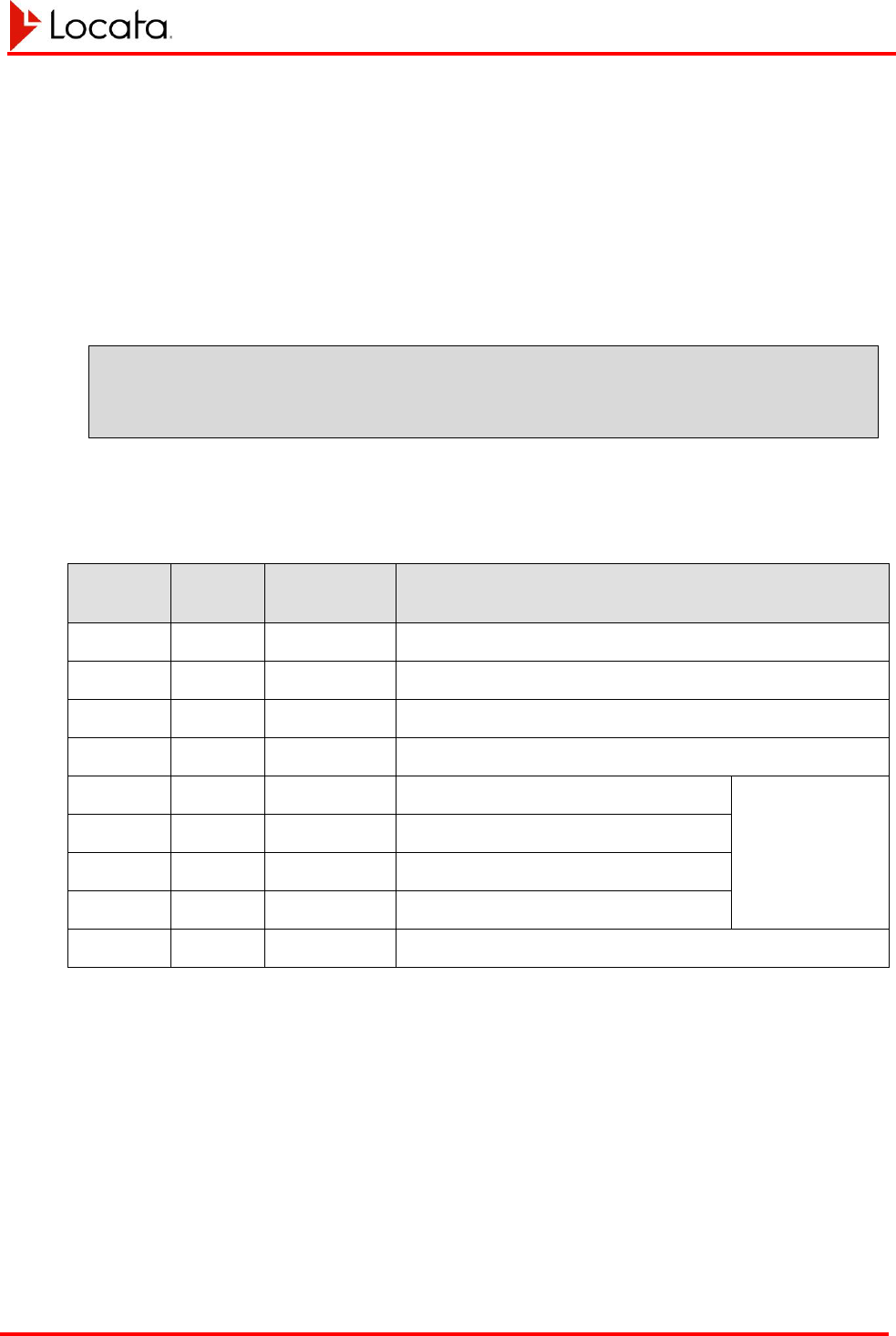
Appendix
Message Definitions LocataLite User's Manual
Locata-LocataLite-UserManual v8r0
27-May-2014
A-2
A.1.1 GPS GSV Message
The GSV message shows the satellites, or in this case, the Locatalites, in view based on
their almanac data. It also shows the current ability to track this signal. One GSV
sentence can provide data for up to 4 signals. The NMEA standard dictates a maximum
of 3 GSV messages providing information on a maximum of 12 Signals.
GSV Format
$GPGSV,3,1,6,01,01,083,21,02,05,308,19,03,07,344,18,04,01,228,10*7
5
GSV Fields
Table 17, GSV message fields
Field
Symbol
Description
(units)
Range / Options / Comments
1
GSV
Satellites in view
2
x
3
Number of sentences of this type in this cycle
3
x
1
Sentence number in cycle
4
x
6
Number of Locata Signals in view
5+4*(n-1)
x
01
Locatalite Signal PRN number
For n=1-4;
4 satellites per
sentence
6+4*(n-1)
x
01
Elevation, degrees
7+4*(n-1)
x
083
Azimuth, degrees
8+4*(n-1)
x
21
SNR, dB, null when not tracking
21
x
*75
Checksum data. Always begins with *

Appendix
Message Definitions LocataLite User's Manual
Locata-LocataLite-UserManual v8r0
27-May-2014
A-3
A.2 LOCATA PROPRIETARY MESSAGES
Since a Locata System differs in some important ways from a standard GPS system, it
must also use a few proprietary messages to convey device and system status. This
section describes the Locata proprietary messages LocataLites use at this time.
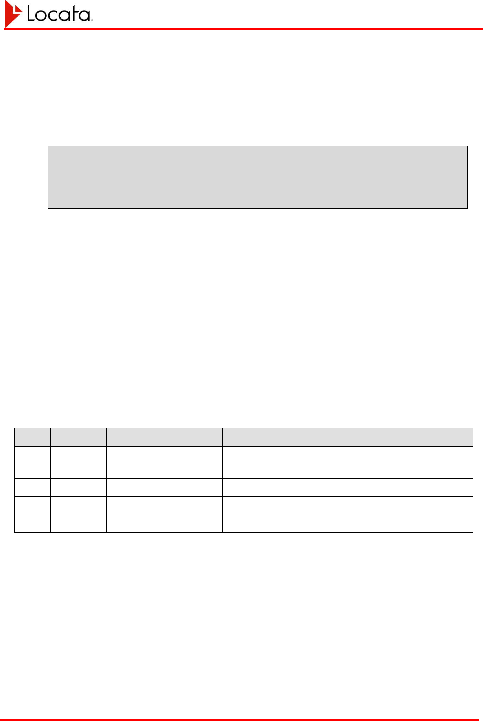
Appendix
Message Definitions LocataLite User's Manual
Locata-LocataLite-UserManual v8r0
27-May-2014
A-4
A.2.1 Locata ETH Message
This message allows querying or setting of the Ethernet configuration.
ETH Format
$GPLOC,ETH*22\r\n
$GPLOC,ETH,<mode>,<address>,<netmask>,<gateway>*CS\r\n
The LocataLite interprets the shorter format as a query request. It will respond with the
full message containing the current Ethernet configuration.
The LocataLite interprets the longer format message as a command to set the Ethernet
configuration. The LocataLite does not respond to the long message. You can verify
that a command to set the Ethernet configuration has taken effect by sending a query
message for the present configuration after making a change, which should reflect the
updated configuration.
Note that as per the NMEA standard the checksum is optional. If the checksum is
omitted the ‘*’ should also be omitted.
ETH Fields
Table 18, ETH message fields
Field
Symbol
Description (units)
Range / Options / Comments
1
mode
DHCP or static
0 – static IP mode
1 – DHCP mode
2
address
IPv4 IP address
e.g. 192.168.1.111 (only relevant for static IP mode)
3
netmask
IPv4 netmask
e.g. 255.255.255.0 (only relevant for static IP mode)
4
gateway
IPv4 gateway address
e.g. 192.168.1.1 (only relevant for static IP mode)
Appendix
Message Definitions LocataLite User's Manual
Locata-LocataLite-UserManual v8r0
27-May-2014
A-5
A.2.2 Locata ENV Message
This message reports the internal temperature and supply voltage for the LocataLite.
ENV Format
$GPSLOC,ENV,<week>,<tow_s>,<t1>,<t2>,<t3>,<t4>,<t5>,<tmax>,<Vss>*C
S\r\n
ENV Fields
Table 19, ENV message fields
Field
Symbol
Description (units)
Range / Options / Comments
1
Week
Week number [week]
GPS week number
2
tow_s
Time of week [s]
Seconds into the week
3
t1
CPU temperature [ºC]
Resolution to nearest °C
4
t2
CPU PCB temperature [ºC]
Resolution to nearest °C
5
t3
FPGA temperature [ºC]
Resolution to nearest °C
6
t4
FPGA PCB temperature [ºC]
Resolution to nearest °C
7
t5
TCXO PCB temperature [ºC]
Resolution to nearest °C
8
tmax
Max of t1 through t5 [ºC]
Resolution to nearest °C
9
Vss
Supply voltage [V]
Resolution to mV
Appendix
Message Definitions LocataLite User's Manual
Locata-LocataLite-UserManual v8r0
27-May-2014
A-6
A.3 SIGNAV PROPRIETARY MESSAGES
A.3.1 SigNav uTevo SSR Message
This section describes the SigNav proprietary SSR message the uTevo GPS timing
receiver sends over its serial interface to accompany the pulse-per-second timing
supplied to the LocataLite.
SSR Format
$PSGNR,SSR,yyyymmdd,hhmmss,x,x.x,x,x,x,x,x,x,x,hh*CS\r\n
SSR Fields
Table 20, SSR fields
Field
Symbol
Description (units)
Range / Options
1
yyyymmd
d
Date: year, month, day
1980 – 2099, 01 – 12, 01 – 31
2
hhmmss
Time
Hours, minutes, seconds
3
x
Alignment
1 – UTC alignment
0 – GPS alignment
4
x.x
UTC Offset (seconds)
0 – 128
Will be 0 until UTC parameters are
known.
5
x
Leap Second Pending
+1 – A positive leap scheduled
0 – No leap scheduled
-1 – A negative leap scheduled
6
x
Position status
0 – Position unknown
1 – Position good to 300 m
2 – Self-survey complete
7
x
Holdover
0 – Receiver is fixing
1 – Receiver is in holdover
8
x
TS Inner Tolerance
0 – Not in inner tolerance
1 – In inner tolerance
9
x
TS Outer Tolerance
0 – Not in outer tolerance
1 – In outer tolerance
10
x
Frequency Inner
Tolerance
0 – Not in inner tolerance
1 – In inner tolerance

Appendix
Message Definitions LocataLite User's Manual
Locata-LocataLite-UserManual v8r0
27-May-2014
A-7
Field
Symbol
Description (units)
Range / Options
11
x
Frequency Outer
Tolerance
0 – Not in outer tolerance
1 – In outer tolerance
12
hh
Error conditions (bit
flags)
Bit 0 – Hardware failure
Bit 1 – TS alignment failure
Bit 2 – Freq control failure
Bit 3 – Antenna under current
Bit 4 – Antenna over current
Bits 5 - 7 – Reserved for future use
Notes
1. The SSR report outputs automatically by default.
2. The SSR report cannot be switched off in the uTevo.
3. The SSR output rate is 1Hz.
4. The SSR report output is expected to start 10ms-50ms after the PPS.
5. The uTevo NMEA protocol speed is 115,200 baud
6. The LocataLite software will also process the message if the date is combined to a
single YYYYMMDD field (i.e. no comma separation)
Appendix
Message Definitions LocataLite User's Manual
Locata-LocataLite-UserManual v8r0
27-May-2014
A-8
A.4 LEICA PROPRIETARY MESSAGES
A.4.1 Leica TPV Message
The table below presents the TPV message fields. This is almost identical to the GPS
TPV messages with the exception of the solution type. The solution type flags are
unique to Locata.
TPV Format
$PLEIR,TPV,x.x,x,0,x,0,x,x,x,0,0,x.x,x.x,x.x,x.x,x.x,x.x,x.x,x.x,x
.x,x.x,x.x,x,
x,x,*CS\r\n
TPV Fields
Table 21, TPV message fields
Field
Symbol
Description (units)
Range / Options / Comments
0
Headers
$PLEIR,TPV,
1
x.x
UTC Time
hhmmss.ss
2
x
UTC Date
ddmmyy
3
0
Latency
milliseconds
4
X
Dynamics
0: Roving
1: Static
5
0
Confidence
Not used, fill with “0”
6
x
Solution Type
See Note 1
7
x
External Aiding
See Note 2
8
x
Failure Flag
See Note 3
9
0
Position Format
Always “0”. Only support geodetic output at date
See Note 4
10
0
Datum
Always “0”. Geodetic

Appendix
Message Definitions LocataLite User's Manual
Locata-LocataLite-UserManual v8r0
27-May-2014
A-9
Field
Symbol
Description (units)
Range / Options / Comments
11
x.x
Latitude
DDMM.FFFFFFF
2 fixed digits for degrees; 2 fixed digits for
minutes; and 7 digits for decimal-fraction of
minutes resulting in approximate resolution of
0.0000001 min * (1 deg/60 min) * 110,000 (m/deg
@ equator = 0.000183
e.g. 2914.9456371 = 29°14.9456371’
12
x.x
Longitude
DDDMM.FFFFFFF
3 fixed digits for degrees; 2 fixed digits for
minutes; and 7 digits for decimal-fraction of
minutes resulting in approximate resolution of
0.0000001 min * (1 deg/60 min) * 110,000 (m/deg
@ equator = 0.000183
e.g. 2914.9456371 = 29°14.9456371’
13
x.x
Altitude
Variable length to the left of the decimal and 3
digits after the decimal
xxxx.xxx
14
x.x
Latitude Quality (m)
xx.xx (from navigation solution)
15
x.x
Longitude Quality (m)
xx.xx (from navigation solution)
16
x.x
Altitude Quality (m)
xx.xx (from navigation solution)
17
x.x
Speed over the Ground
(SOG) (knots)
Variable length to the left of the decimal and 3
digits after the decimal.
xxxx.xxx
0.01 knot*(0.514 m/s per knot) = 0.000514 m/s
resolution
0.02 fill with zeros when not calculating SOG
18
xx.xx
Course over the Ground
(COG) (degrees)
Variable length to the left of the decimal and 1 digit
after the decimal
xxxx.x
Clockwise relative to true North 0-359.9°
Fill with zeros when not calculating COG
19
x.x
HDOP
Variable length to the left of the decimal and 1 digit
after the decimal. Dimensionless
20
x.x
TDOP
Variable length to the left of the decimal and 1 digit
after the decimal. Dimensionless
21
x.x
VDOP
Variable length to the left of the decimal and 1 digit
after the decimal. Dimensionless
22
x
Number of visible satellites
Integer
Number of signals available from current
position based on line of sight measurements
with current antenna masks and no obstructions
23
x
Number of tracked
LocxataLites
Integer
Number of TX signals tracked with carrier (state
9)

Appendix
Message Definitions LocataLite User's Manual
Locata-LocataLite-UserManual v8r0
27-May-2014
A-10
Field
Symbol
Description (units)
Range / Options / Comments
24
x
Number of LocataLites in
position solution
Integer
Number of measurements used in the
navigation solution
25
Checksum
Notes
The following table presents the values permitted for describing the Solution Type.
Table 22, TPV message Solution Type field
Value
Meaning
10
Startup mode; Locata position not yet available
11
Locata Code Position
12
Locata Phase Position
13
Locata GPS Assisted Phase Position
14
Stale Locata Position
21
GPS Differential code position
22
GPS Differential phase position
23
GPS Non-differential position
253
GPS differential position based on prediction, not
measurements
254
GPS differential phase position based on prediction,
not measurements
255
GPS non-differential position based on prediction, not
measurements
The following table presents the values permitted for describing External Aiding.
Only options 1 and 2 are currently supported in the Locata navigation solution
Table 23, TPV message, External Aiding field
Value
Meaning
0
None
1
Height fixed – 2D navigation solution
2
Position fixed – time and height solution
3
Position and height fixed – Time solution

Appendix
Message Definitions LocataLite User's Manual
Locata-LocataLite-UserManual v8r0
27-May-2014
A-11
The following table presents the values permitted for describing the Failure Flag
Table 24, TPV message, Failure Flag field
Value
Meaning
0
Position OK
1
Position Bad
The following table presents the values permitted for describing the Position Format
Table 25, TPV message Position Format field
Value
Meaning
0
WGS Geodetic
1
Local Grid
2
WGS Cartesian
3
Local Cartesian
4
Local Geodetic
5
WGS Geodetic with Qxx elements
6
Local Grid with Qxx elements
7
WGS Cartesian with Qxx elements
8
Local Cartesian with Qxx elements
9
Local Geodetic with Qxx elements
Appendix
Message Definitions LocataLite User's Manual
Locata-LocataLite-UserManual v8r0
27-May-2014
A-12
A.4.2 Leica LVR Message
The Leica LVR message cites the antenna offsets from the Leica antenna phase center to
the survey reference point.
LVR Format
$PLEIR,LVR,x.x,x,x.x,x.x,x.x,*CS\r\n
LVR Fields
Table 26, LVR message fields
Field
Symbol
Description (units)
Range / Options / Comments
0
Headers
$PLEIR,LVR,
1
x.x
UTC Time
hhmmss.ss
2
x
UTC Date
ddmmyy
3
x.x
North Offset
Meters
4
x.x
East Offset
Meters
5
x.x
Down Offset
Meters
5
checksum

Appendix
Configuration File LocataLite User's Manual
Locata-LocataLite-UserManual v8r0
27-May-2014
A-13
APPENDIX B CONFIGURATION FILE
What follows is the contents of a standard LocataLite configuration file including
documentation of all user configuration options.
#############################################################################
# Configuration File: loclite_release_config.txt [2014-05-14 at 02:44:40]
#############################################################################
#############################################################################
# LocataLite Device Type
#
# There is only one Master in a given network. The remaining LocataLites
# are Slaves. In general you should designate the LocataLite that is best
# placed to provide a timing reference for the network as the Master
# LocataLite. That is, the Master should be that LocataLite having the
# shortest paths, including using the fewest TimeLoc hops where necessary
# to all other LocataLites. This arrangement would provide the cleanest
# TimeLoc performance operationally. However, other reasons may prompt a
# different selection for Master, such as accessibility or elevation.
#
# Options: MASTER, MASTER_WITH_GPS_SYNC, SLAVE
#
Device_Type = MASTER;
#############################################################################
# LocataLite Device ID
#
# This is a numeric assignment to each LocataLite which determines the
# pseudorandom spreading code and TDMA timeslot used by each device.
#
# Device ID selection:
#
# - Each LocataLite device must be configured with a unqiue ID different from
# all other LocataLites in the same network.
#
# - Maximising usage of device IDs from within each decade series ensures
# overlap is avoided in small networks and kept to a minimum in larger
# networks.
#
# 10 or fewer devices - operators should choose device IDs within within
# the same decade. For example within the range 1-10
# or 11-20. This approach maximises network
# performance by ensuring that all active TDMA
# transmissions do not overlap.
# - Examples:
# 7 devices: 1,2,3,4,5,6,7
# 10 devices: 1,2,3,4,5,6,7,8,9,10
#
# More than 10 devices - operators should initially choose device IDs within
# the same decade (as above) and then repeat this
# process by only adding additional IDs from within
# another decade until this is full, etc.

Appendix
Configuration File LocataLite User's Manual
Locata-LocataLite-UserManual v8r0
27-May-2014
A-14
# - Examples:
# 16 devices: 1,2,3,4,5,6,7,8,9,10,11,12,13,14,15,16
# 22 devices: 1,2,3,4,5,6,7,8,9,10,11,12,13,14,15,16,
# 17,18,19,20,21,22
#
# - It is convention to assign a loclite_device_id of 1 to the Master
# LocataLite, although it is not necessary to do so.
#
# Notes:
#
# - Note that the TDMA transmission sequences have been carefully defined such
# that the impact of transmission overlap possible in larger networks is
# minimised. Key statistical properties of transmission sequence
# combinations were optimised during this process to ensure performance is
# consistent and reliable in these scenarios regardless of the specific
# device ID combinations in play.
#
Loclite_Device_ID = 1;
#############################################################################
# Reference device for TimeLoc
#
# Relevant to SLAVE LocataLites only (not Master LocataLites)
#
# Defines the reference device ID used to acquire TimeLoc and synchronise with
# the network. Slave LocataLites will search for the LocataLite cited in this
# field when searching for a TimeLoc signal at boot.
#
# Typically a Slave LocataLite will have a direct line-of-sight path to the
# Master LocataLite and so operators should you should set this field to match
# the loclite_device_id of that Master LocataLite. When this direct line-of-
# sight path does not exist operators will need to set this field to match the
# loclite_device_id of another Slave LocataLite in the network which is
# TimeLoc'd directly from the Master LocataLite, or alternatively to another
# Slave LocataLite with the shortest path (fewest and shortest hops) to the
# Master LocataLite from itself.
#
Reference_Device_ID = 2;
#############################################################################
# Rx and Tx Antenna of this LocataLite
#
# Note that this parameters are ignored when self-survey is enabled.
#
# LocataLiteRx is the Receiver Antenna.
# LocataLiteTx1 uses the antenna connected to port Tx1 on the LocataLite.
# LocataLiteTx2 uses the antenna connected to port Tx2 on the LocataLite.
#
# LocataLiteRx/LocataLiteTx1/LocataLiteTx2:
#
# Field Description Range
# ===== =========== =====
# Coords Rx Antenna coordinates [X,Y,Z] ECEF XYZ co-ordinates [m]
# Attitude Yaw, Pitch, Roll, Validity [0 - 359,-90-90,-90-90,YES/NO]
# RxAntennaType Possible types are: [ 0-5 ]

Appendix
Configuration File LocataLite User's Manual
Locata-LocataLite-UserManual v8r0
27-May-2014
A-15
#
# 0 - None
# 1 - AeroAntenna Patch (AT2400)
#
# Name of this site: [INSERT NAME HERE]
#
LocataLiteRx: Coords[ -4431684.7961, 2636076.3421, -3742707.4700 ] Attitude[
360, -90, -90, NO ] RxAntennaType[ 1 ];
LocataLiteTx1: Coords[ -4431684.7961, 2636076.3421, -3742707.4700 ] Attitude[
360, -90, -90, NO ] TxAntennaType[ 1 ];
LocataLiteTx2: Coords[ -4431683.5388, 2636075.3371, -3742706.1663 ] Attitude[
360, -90, -90, NO ] TxAntennaType[ 1 ];
#############################################################################
# LocataLite Self Survey
#############################################################################
# The following parameters apply to the LocataLite GPS self-survey feature.
#
# When this feature is enabled the LocataLiteRx/LocataLiteTx ECEF XYZ
# co-ordinate parameters are ignored.
#############################################################################
# Enable/disable self-survey
#
# Options: ON, OFF (default)
#
SelfSurvey_enabled = OFF;
#############################################################################
# Select the level of GPS dependency. This series of parameters changes the
# LocataLite behaviour when valid TPV data is unavailable during each stage
# of operation.
#
# Valid options are: YES (default) / NO
#
# Any combination may be selected to achieve the desired operation.
#
# SelfSurvey_GPS_rqd_to_load_nv_posn:
#
# Defines whether GPS position data is required to validate a previous survey
# position loaded from non-volatile memory at boot.
#
# YES - non-volatile position must be validated before it can be used
# NO - non-volatile position will be used even if we can't validate it,
# position will ultimately be verified if GPS becomes available
#
# SelfSurvey_GPS_rqd_during_full_survey:
#
# Defines whether the LocataLite reports bad health if GPS data is not
# available at any point during the full survey.
#
# YES - LocataLite will assert bad health during the full survey if GPS is
# not present or has bad quality
# NO - LocataLite can assert good health during the full survey even if

Appendix
Configuration File LocataLite User's Manual
Locata-LocataLite-UserManual v8r0
27-May-2014
A-16
# GPS is not present or has bad quality
#
# SelfSurvey_GPS_rqd_during_monitoring:
#
# Defines whether the LocataLite reports bad health if GPS data is not
# available at any point during on-going position monitoring.
#
# YES - LocataLite will assert bad health during on-going monitoring if GPS
# is not present or has bad quality
# NO - LocataLite can assert good health during on-going monitoring even
# if GPS is not present or has bad quality
#
# SelfSurvey_movement_asserts_bad_health:
#
# Set whether detecting movement is cause for setting the LocataLite health
# as bad in the NAV data.
#
# YES - LocataLite will assert bad health if movement is detected
# NO - LocataLite can assert good health even if movement is detected
#
SelfSurvey_GPS_rqd_to_load_nv_posn = YES;
SelfSurvey_GPS_rqd_during_full_survey = YES;
SelfSurvey_GPS_rqd_during_monitoring = YES;
SelfSurvey_movement_asserts_bad_health = YES;
#############################################################################
# Set the vertical offsets between the GPS antenna and the LocataLite
# antennas in metres.
#
# The GPS antenna should be above all LocataLite antennas and the offsets
# given as positive numbers. e.g. 0.015
#
# Defaults:
# Tx1 = 0.200
# Tx2 = 2.200
# Rx = 0.350
#
# Units: [metres]
#
SelfSurvey_Tx1_offset = 0.200;
SelfSurvey_Tx2_offset = 2.200;
SelfSurvey_Rx_offset = 0.350;

Appendix
Configuration File LocataLite User's Manual
Locata-LocataLite-UserManual v8r0
27-May-2014
A-17
#############################################################################
# Comms Configuration
#############################################################################
#############################################################################
# Serial Port Assignment:
#
# Each of the two external serial ports (COMPORT_1, COMPORT_2) may be
# assigned one of the following values:
#
# IO_PORT_NONE - no i/o assigned to this serial port
# IO_PORT_LBMP - input and output are LBMP messages
# IO_PORT_ASC - input user ascii commands, output is ASC measurement data
# IO_PORT_ASC_MET - input is nmea from an external met unit, output is ASC
# measurement data and requests for met data
# IO_PORT_GPS - input is nmea from an external gps unit, output is requests
# data from the gps unit
# IO_PORT_MET - input is nmea from an external met unit, output is requests
# for met data
#
# IMPORTANT: It is not permissible to assign the same protocol to two ports.
#
COMPORT_1 = IO_PORT_ASC;
COMPORT_2 = IO_PORT_GPS;
#############################################################################
# Serial port baud rate:
#
# The supported rates are:
#
# 9600
# 19200
# 38400
# 57600
# 115200
# 230400
#
COMPORT_1_BAUD = 115200;
COMPORT_2_BAUD = 115200;
#############################################################################
# LBMP message scheduling
#
# LBMP message scheduling provides the ability for a user to define a set of
# desired messages to be output at various rates.
#
# The format of this element is:
#
# LBMP_schedule_message = <msg_id>, <rate>
#
# Where:
#
# <msg_id> : one of the set of LBMP message IDs (see the LBMP ICD for
# a list of supported message IDs)
#

Appendix
Configuration File LocataLite User's Manual
Locata-LocataLite-UserManual v8r0
27-May-2014
A-18
# <rate> : MEAS_RATE : output message at the measurement rate
# NAV_RATE : output message at the nav solution rate
# ON_UPDATE : output message whenever the underlying data changes
# <period_in_seconds> : a period in seconds (treated as a float)
#
# A maximum of 16 LBMP_schedule_message entries are allowed. Only one rate
# per message ID is accepted. If multiple requests for the same message ID
# are provided only the final request will apply.
#
# It is up to the user to schedule any desired messages, no LBMP messages
# are scheduled to output by default.
#
# These elements only apply when IO_PORT_LBMP is selected for at least one
# COM port.
#
LBMP_schedule_message = 1001, 1.0;
LBMP_schedule_message = 2001, 5;
LBMP_schedule_message = 6101, ON_UPDATE;
LBMP_schedule_message = 7001, ON_UPDATE;
LBMP_schedule_message = 8001, ON_UPDATE;
LBMP_schedule_message = 9001, ON_UPDATE;
LBMP_schedule_message = 9002, ON_UPDATE;
LBMP_schedule_message = 9003, ON_UPDATE;
LBMP_schedule_message = A001, 60;
#############################################################################
# Specify the initial time and date in the following format:
#
# Date = YYYY/MM/DD
# Time = HH:MM:SS
# GPS/UTC offset = [offset in seconds]
# - where UTC_time = GPS_time - offset)
#
Date = 2014/05/14;
Time = 02:44:40;
GPS_UTC_Offset = 16;
#############################################################################
# Operating_Region
#
# Set the region in which this LocataLite is operating for the purposes of
# spectrum management. This parameter will be used with the Frequency_Plan
# parameter to limit the maximum output power of the signals that are
# broadcast from the LocataLite.
#
# # | Location |
# -----|-----------------------------|
# 1 | US (FCC compliant, default) |
# -----|-----------------------------|
#
Operating_Region = 1;

Appendix
Configuration File LocataLite User's Manual
Locata-LocataLite-UserManual v8r0
27-May-2014
A-19
#############################################################################
# Frequency_Plan
#
# Set the carrier frequencies to be used by the system. Default is plan '2'.
# This single parameter defines the frequencies for all four signals from the
# LocataLite. It is critical that this parameter be configured consistently
# by all LocataLites and Rovers across a LocataNet.
#
# # | Carrier 1 | Carrier 2 |
# -----|--------------------------|----------------------------|
# 1 | S02 | 2411.211 MHz | S62 | 2472.591 MHz |
# 2 | S02 | 2411.211 MHz | S52 | 2462.361 MHz |
# -----|--------------------------|----------------------------|
#
Frequency_Plan = 1;
#############################################################################
# LT_Board_Revision
#
# Specify which revision of transmitter hardware is present in this LocataLite.
# This information is used to determine the correct settings to achieve the
# requested output power. In future the LocataLite will be able to detect
# the hardware revisions itself and this parameter will be removed
#
# There are currently two supported boards:
#
# 1 - the original tx board
# 2 - the new tx board produced in 2012
#
# (Note that updated transmitter boards may be retrofitted to first generation
# systems)
#
LT_Board_Revision = 2;
#############################################################################
# LT_Tx_Power_dBm[]
#
# Set the transmit power for each of the four signals from this LocataLite.
# The powers are set in units of dBm with a special value 'max' which will
# use the maximum allowed power for the given operating region and frequency
# plan.
#
# Range : -49 to +20 dBm
# Step size : 1 dB
# Special cases : max
#
# Restrictions:
#
# (a) The max Tx power depends on the region in which the LocataLite is
# operating according to the 'Operating_Region' parameter and the
# frequency plan that has been selected. If a value higher than
# the maximum allowed power for that region and frequency is
# selected the LocataLite will limit the power to the maximum
# allowed value for that region and frequency.
#
# (b) Note that it is important to avoid setting too great a difference

Appendix
Configuration File LocataLite User's Manual
Locata-LocataLite-UserManual v8r0
27-May-2014
A-20
# between the transmit powers for two different transmit signals.
# Doing so can introduce a persistent near/far effect where the stronger
# signal causes interference on the weaker signal. The maximum transmit
# power difference allowed between any two signals is therefore
# restricted to 10dB.
#
# Channel map:
#
# 0 --> A
# 1 --> B
# 2 --> C
# 3 --> D
#
LT_Tx_Power_dBm[0] = max;
LT_Tx_Power_dBm[1] = max;
LT_Tx_Power_dBm[2] = max;
LT_Tx_Power_dBm[3] = max;
#############################################################################
# Network Longest Edge (m)
#
# This value defines the longest range between any two LocataLites in the
# Locata network.
#
# Note: this parameter is only used by a MASTER or MASTER_WITH_GPS_SYNC
# LocataLite. SLAVE LocataLites will ignore the configuration file
# value as it is transmit to them by their TimeLoc reference LocataLite.
#
Network_Longest_Edge = 2500.0;
#############################################################################
# Type of GPS Receiver to which Master will synchronise
# Note: Set to None if GPS synchronisation is not required
#
# Options: uTevo, TSC4400, JPS, None
#
# Note: this parameter will be ignored for all LocataLite types other than
# MASTER_WITH_GPS_SYNC
#
GPS_Receiver_Type = uTevo;
#############################################################################
# Met Station polling configuration.
# 0 - Do Nothing
# 1 - Poll the Met Station for data
# 2 - Configure the Met Station to output data we understand at boot (default)
#
met_station_polling = 1;

Appendix
Configuration File LocataLite User's Manual
Locata-LocataLite-UserManual v8r0
27-May-2014
A-21
#############################################################################
# Settings related to using the Leica TPV message for self-survey
#
# Used to determing if the message includes valid position or not
# Pls refer to the Leica owi message specs
# Latency in miliseconds (less than)
Msg_Latency = 400;
# Number of succussful searches completed less than
Num_Searched = 11;
# Quality of latitude (less than) in metres
lat_quality = 0.03;
# Quality of longtitude (less than) in metres
lon_quality = 0.03;
# QUality of height (less than) in metres
height_quality = 0.05;
# Speed over ground less than in knots
Sog = 0.1;
# HDOP less than
HDOP = 4;
# TDOP less than
TDOP = 5;
# VDOP less than
VDOP = 6;
# Number satellites in Pos Computation more than
sats_used = 5;
#############################################################################
# Logging
#############################################################################
# Enable measurement logging. This allows messages generated in the given
# protocol to be saved to internal flash memory.
#
# Valid options are:
#
# OFF : nothing is logged to file (default)
# ON : the application selects which port gets logged (LBMP preferred)
# ASC : the ASC port output will be logged to file
# LBMP : the LBMP port output will be logged to file
#
Measurement_Log = OFF;
