Lochinvar Power Fin 1002 Users Manual PBX PFX USER Rev B.qxp
1002 to the manual ec733567-2cc3-48f9-8264-cc23fef3f4f3
2015-02-09
: Lochinvar Lochinvar-Power-Fin-1002-Users-Manual-575692 lochinvar-power-fin-1002-users-manual-575692 lochinvar pdf
Open the PDF directly: View PDF ![]() .
.
Page Count: 16

User Manual
Models: 502, 752, 1002, 1302,
1501, 1701, and 2001
Up To 5:1 Turndown
If the information in this manual is not followed exactly, a fire
or explosion may result causing property damage, personal
injury or loss of life.
This appliance MUST NOT be installed in any location where
gasoline or flammable vapors are likely to be present.
WHAT TO DO IF YOU SMELL GAS
• Do not try to light any appliance.
• Do not touch any electric switch; do not use any
phone in your building.
• Immediately call your gas supplier from a neighbor’s phone.
Follow the gas supplier’s instructions.
• If you cannot reach your gas supplier, call the fire
department.
• Installation and service must be performed by a qualified
installer, service agency, or the gas supplier.
Save this manual for future reference.
WARNING

User’s Information Manual
2
Hazard definitions . . . . . . . . . . . . . . . . . . . . . . . . . . . . . . . . . . . . . . . . . . . . . . . . 2
Please read before proceeding . . . . . . . . . . . . . . . . . . . . . . . . . . . . . . . . . . . . . . 3
1. Maintenance schedule . . . . . . . . . . . . . . . . . . . . . . . . . . . . . . . . . . . . . . . . . . 5
Maintenance procedures . . . . . . . . . . . . . . . . . . . . . . . . . . . . . . . . . . . . . . . 6
2. Operating instructions . . . . . . . . . . . . . . . . . . . . . . . . . . . . . . . . . . . . . . . . . . 8
3. SMART SYSTEM control module . . . . . . . . . . . . . . . . . . . . . . . . . . . . . . . . . . . 9
Access modes . . . . . . . . . . . . . . . . . . . . . . . . . . . . . . . . . . . . . . . . . . . . . . . . 9
Saving parameters . . . . . . . . . . . . . . . . . . . . . . . . . . . . . . . . . . . . . . . . . . . . 9
Parameter table . . . . . . . . . . . . . . . . . . . . . . . . . . . . . . . . . . . . . . . . . . . . . . 10
Viewable and changeable control parameters . . . . . . . . . . . . . . . . . . . . . . 11
Status display screens . . . . . . . . . . . . . . . . . . . . . . . . . . . . . . . . . . . . . . . . . 13
Revision Notes . . . . . . . . . . . . . . . . . . . . . . . . . . . . . . . . . . . . . . . . . . . Back Cover
Contents
Hazard definitions
The following defined terms are used throughout this manual to bring attention to the presence of hazards of various risk levels
or to important information concerning the life of the product.
DANGER
WARNING
CAUTION
CAUTION
NOTICE
DANGER indicates an imminently hazardous situation which, if not avoided, will result in death or
serious injury.
WARNING indicates a potentially hazardous situation which, if not avoided, could result in death or
serious injury.
CAUTION indicates a potentially hazardous situation which, if not avoided, may result in minor or
moderate injury.
CAUTION used without the safety alert symbol indicates a potentially hazardous situation which, if not
avoided, may result in property damage.
NOTICE indicates special instructions on installation, operation, or maintenance that are important but
not related to personal injury or property damage.

Please read before proceeding
User’s Information Manual
3
NOTICE This is a gas appliance and should be
installed by a licensed electrician and/or
certified gas supplier. Service must be
performed by a qualified service
installer, service agency or the gas
supplier.
WARNING If the information in these instructions
is not followed exactly, a fire or
explosion may result causing property
damage, personal injury, or death.
This appliance MUST NOT be installed
in any location where gasoline or
flammable vapors are likely to be
present, unless the installation is such to
eliminate the probable ignition of
gasoline or flammable vapors.
What to do if you smell gas –
• Do not try to light any appliance.
• Do not touch any electric switch; do not use any
phone in your building.
• Immediately call your gas supplier from a neighbors
phone. Follow the gas supplier’s instructions.
• If you cannot reach your gas supplier, call the fire
department.
Installation and service must be performed by a qualified
installer, service agency, or the gas supplier.
Warranty –
Factory warranty (shipped with unit) does not apply to
units improperly installed or improperly operated.
Experience has shown that improper installation or system
design, rather than faulty equipment, is the cause of most
operating problems.
1. Excessive water hardness causing a lime/scale build-up
in the copper tube is not the fault of the equipment and
is not covered under the manufacturer’s warranty (see
Water Treatment and Water Chemistry in the Power-fin
Installation and Operation Manual).
2. Excessive pitting and erosion on the inside of the
copper tube may be caused by too much water velocity
through the tubes and is not covered by the
manufacturer’s warranty (see Boiler Flow Rates and
Temperature Rise for flow requirements in the Power-fin
Installation and Operation Manual).
Checking equipment –
Upon receiving equipment, check for signs of shipping damage.
Pay particular attention to parts accompanying the appliance
which may show signs of being hit or otherwise being
mishandled. Verify total number of pieces shown on the
packing slip with those actually received. In case there is
damage or a shortage, immediately notify the carrier.
Do not use this appliance if any part has been under water.
The possible damage to a flooded appliance can be extensive
and present numerous safety hazards. Any appliance that has
been under water must be replaced.
WARNING Improper installation, adjustment,
alteration, service or maintenance can cause
injury or property damage. Refer to this
manual for assistance or additional
information, consult a qualified installer,
service agency or the gas supplier.
Owner warning –
The information contained in this manual is intended for use
by qualified professional installers, service technicians, or gas
suppliers. Consult your local expert for proper installation or
service procedures.
NOTICE Consult and follow all local Building and
Fire Regulations and other Safety Codes that
apply to this installation. Consult a local gas
utility company to authorize and inspect all
gas and flue connections.
Your conventionally vented gas appliance must have a supply of
fresh air circulating around it during burner operation for
proper gas combustion and proper venting.
WARNING Should overheating occur or the gas supply
fail to shut off, do not turn off or disconnect
the electrical supply to the pump. Instead,
turn off the manual gas control valve to the
appliance at a location external to the
appliance.
Prevention of freezing –
Heat exchangers and headers damaged by freezing are not
covered by warranty.
See Section 7, Startup - Freeze Protection in the Power-fin
Installation and Operation for more information.

User’s Information Manual
4
Please read before proceeding
WARNING To minimize the possibility of serious
personal injury, fire, or damage to your
appliance, never violate the following safety
rules:
1. Boilers and water heaters are heat
producing appliances. To avoid damage
or injury, do not store materials against
the appliance or the vent-air intake
system. Use proper care to avoid
unnecessary contact (especially children)
with the appliance and vent-air intake
components.
2. Never cover your appliance, lean
anything against it, store trash or debris
near it, stand on it or in any way block
the flow of fresh air to your appliance.
3. UNDER NO CIRCUMSTANCES must
flammable materials such as gasoline or
paint thinner be used or stored in the
vicinity of this appliance, vent-air intake
system or any location from which fumes
could reach the appliance or vent-air
intake system.
Codes –
The equipment shall be installed in accordance with those
installation regulations in force in the local area where the
installation is to be made. These shall be carefully followed in all
cases. Authorities having jurisdiction shall be consulted before
installations are made. In the absence of such requirements, the
installation shall conform to the latest edition of the National
Fuel Gas Code, ANSI Z223.1. Where required by the authority
having jurisdiction, the installation must conform to American
Society of Mechanical Engineers Safety Code for Controls and
Safety Devices for Automatically Fired Boilers, ASME CSD-1.
All boilers conform to the latest edition of the ASME Boiler and
Pressure Vessel Code, Section IV. Where required by the
authority having jurisdiction, the installation must comply with
the Canadian Gas Association Code, CAN/CGA-B149.1 and/or
B149.2 and/or local codes. This appliance meets the safe lighting
performance criteria with the gas manifold and control
assembly provided, as specified in the ANSI standards for gas-
fired units, ANSI Z21.13.

1 Maintenance schedule
User’s Information Manual
5
WARNING Follow the maintenance procedures given throughout this manual. Failure to perform the service and
maintenance or follow the directions in this manual could result in damage to the appliance or system, resulting
in severe personal injury, death, or substantial property damage.
Service technician
(see the Power-fin Service Manual for instructions)
General:
• Address reported problems
• Inspect interior; clean and vacuum if
necessary;
• Inspect condensate system and flush with
fresh water
• Check for leaks (water, gas, flue,
condensate)
• Examine venting system
• Check system water pressure/system
piping/expansion tank
• Check control settings
• Check igniter
• Check wiring and connections
• Check flue gas passageways
• Flame inspection (stable, uniform)
• Inspect and clean the burner
• Check manifold gas pressure
• Clean the heat exchanger if flue
temperature is more than 54°F (12.2°C)
above return water temperature.
• Perform start-up checkout and
performance verification per Section 7
in the Power-fin Installation and Operation
Manual.
If combustion or performance
indicate need:
• Clean heat exchanger
• Remove and clean burner using
compressed air only
• Clean the blower wheel
ANNUAL START-UP
Owner maintenance
(see the following pages for instructions)
Daily
• Check appliance area
• Check pressure/temperature
gauge
Monthly
• Check vent piping
• Check air piping
• Check relief valve
• Check condensate drain system
Periodically • Test low water cutoff (if used)
• Reset button (low water cutoff)
Every
6 months
• Check appliance piping (gas and
water) for leaks
• Operate relief valve
End
of season
months
• Shut appliance down (unless
boiler used for domestic hot
water)

User’s Information Manual
6
1 Maintenance schedule
Maintenance procedures
Appliance must be serviced and maintained
WARNING The appliance must be inspected and started
annually at the beginning of the heating
season by a qualified service technician. In
addition, the maintenance and care of the
pool heater designated on page 5 of this
manual and explained on pages 6 and 7 must
be performed to assure maximum appliance
efficiency and reliability. Failure to service
and maintain the appliance and system could
result in equipment failure, causing possible
severe personal injury, death, or substantial
property damage.
NOTICE The following information provides detailed
instructions for completing the maintenance
items listed in the maintenance schedule on
page 5. In addition to this maintenance, the
appliance must be serviced and started up at
the beginning of each heating season by a
qualified service technician.
Check appliance area
WARNING To prevent potential of severe personal
injury, death, or substantial property
damage, eliminate all materials discussed
below from the boiler/water heater vicinity
and the vicinity of the boiler/water heater
combustion air inlet. If contaminants are
found:
Remove products immediately from the area.
If they have been there for an extended
period, call a qualified service technician to
inspect the appliance for possible damage
from acid corrosion.
If products cannot be removed, immediately
call a qualified service technician to re-pipe
vent and air piping and locate vent
termination/air intake away from
contaminated areas.
1. Combustible/flammable materials -- Do not store
combustible materials, gasoline or any other flammable
vapors or liquids near the appliance. Remove
immediately if found.
2. Air contaminants -- Products containing chlorine or
fluorine, if allowed to contaminate the appliance intake
air, will cause acidic condensate in the appliance. This will
cause significant damage to the appliance if allowed to
continue.
Check vent piping
1. Visually inspect the flue gas vent piping for any signs of
blockage, leakage, or deterioration of the piping. Notify
your qualified service technician at once if you find any
problems.
WARNING Failure to inspect the vent system as noted
above and have it repaired by a qualified
service technician can result in vent system
failure, causing severe personal injury or
death.
Check pressure/temperature gauge
1. Make sure the pressure reading on the boiler pressure/
temperature gauge does not exceed 24 PSI. Higher
pressure may indicate a problem with the expansion
tank.
2. Contact a qualified service technician if problem persists.
Check vent piping
1. Visually inspect the flue gas vent piping for any signs of
blockage, leakage, or deterioration of the piping. Notify
your qualified service technician at once if you find any
problems.
WARNING Failure to inspect the vent system as noted
above and have it repaired by a qualified
service technician can result in vent system
failure, causing severe personal injury or
death.
Check air piping
1. Visually inspect the air inlet elbow to be sure it is
unobstructed. Inspect the entire length of air piping to
ensure piping is intact and all joints are properly sealed.
2. Call your qualified service technician if you notice any
problems.
Check relief valve
1. Inspect the appliance relief valve and the relief valve
discharge pipe for signs of weeping or leakage.
2. If the relief valve often weeps, immediately contact your
qualified service technician to inspect the appliance
and system.
1 Maintenance schedule (continued)
User’s Information Manual
7
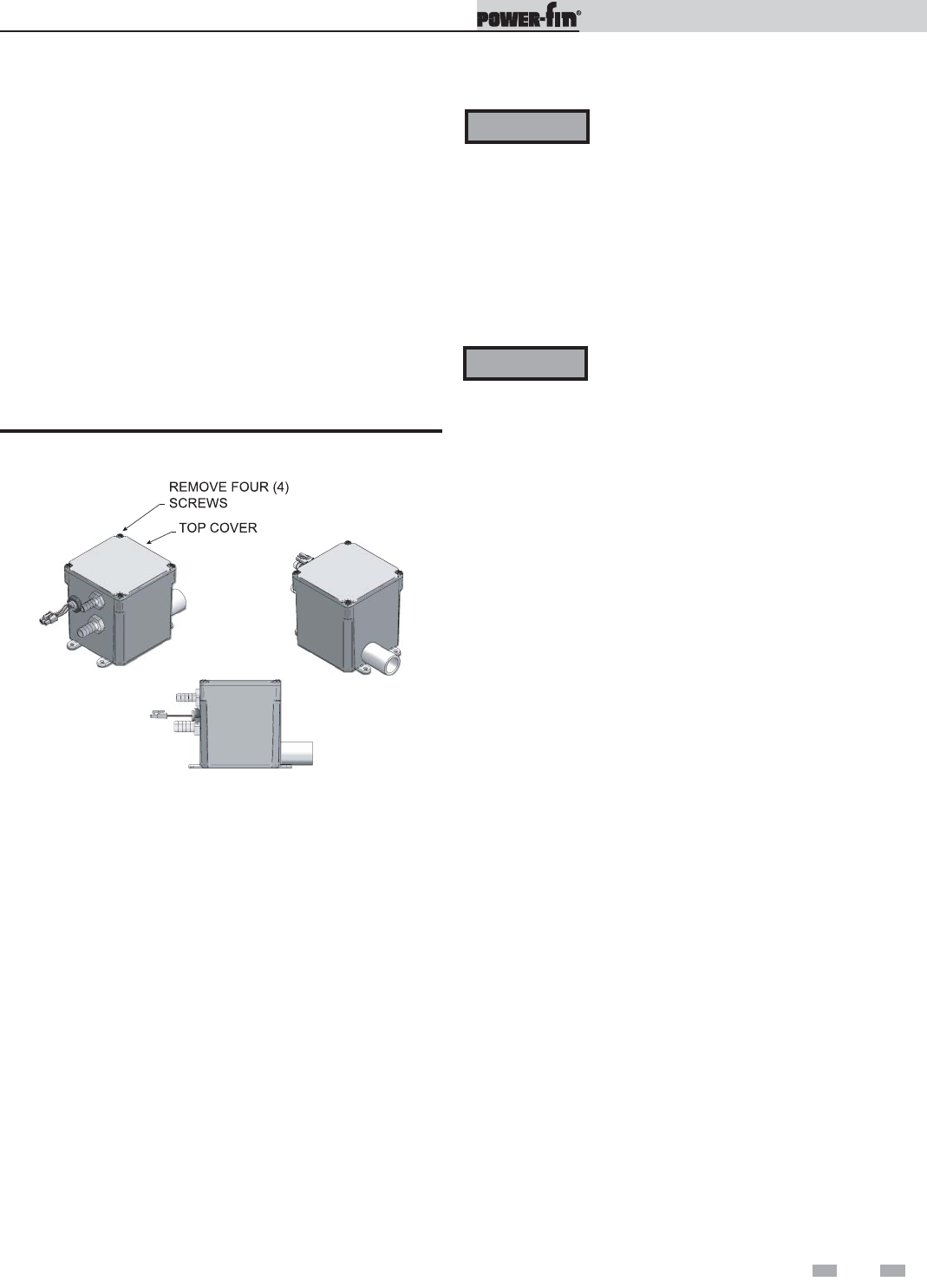
Inspect condensate system
1. Inspect the condensate drain line, condensate PVC fittings,
and condensate trap on an annual basis.
Figure 1-1_Condensate Trap
Flush condensate trap with water
1. Remove the four (4) screws securing the top cover to the
condensate trap and remove the cover (reference FIG. 1-1).
2. Locate the plastic ball inside the float tube. Verify there is
nothing under the ball causing it to not seat properly.
3. If necessary, flush with fresh water until the water begins to
pour out of the drain.
4. Replace the top cover on the condensate trap.
5. Replace the four (4) screws removed in Step 1.
WARNING Have leaks fixed at once by a qualified service
technician. Failure to comply could result in
severe personal injury, death, or substantial
property damage.
Operate relief valve
1. Before proceeding, verify that the relief valve outlet has
been piped to a safe place of discharge, avoiding any
possibility of scalding from hot water.
3. Replace the front access door.
Test low water cutoff (if installed)
1. If the system is equipped with a low water cutoff, test the
low water cutoff periodically during the heating season,
following the low water cutoff manufacturer’s
instructions.
Reset button (low water cutoff)
1. Testing the low water cutoff shuts the unit off. Press the
RESET button on the low water cutoff bracket to turn the
unit back on.
Check appliance piping (gas and water)
1. Remove the appliance front access door and perform a gas
leak inspection per steps 1 through 7 of the Operating
Instructions on page 8. If gas odor or leak is detected,
immediately shut down the appliance following the
procedures on page 8. Call a qualified service technician.
2. Visually inspect for leaks around water piping.
Also inspect the circulators, relief valve, and fittings.
Immediately call a qualified service technician to repair
any leaks.
WARNING To avoid water damage or scalding due to
valve operation, a metal discharge line must
be connected to the relief valve outlet and
run to a safe place of disposal. This discharge
line must be installed by a qualified heating
installer or service technician in accordance
with the instructions in the Power-fin
Installation and Operation Manual. The
discharge line must be terminated so as to
eliminate possibility of severe burns or
property damage should the valve discharge.
2. Read the boiler pressure/temperature gauge to make
sure the system is pressurized. Lift the relief valve
top lever slightly, allowing water to relieve through
the valve and discharge piping.
3. If water flows freely, release the lever and allow the valve
to seat. Watch the end of the relief valve discharge pipe
to ensure that the valve does not weep after the line has
had time to drain. If the valve weeps, lift the seat again to
attempt to clean the valve seat. If the valve continues to
weep afterwards, contact your qualified service
technician to inspect the valve and system.
4. If water does not flow from the valve when you lift the
lever completely, the valve or discharge line may be blocked.
Immediately shut down the appliance, following
the operating instructions on page 8 of this manual. Call
your qualified service technician to inspect the appliance
and system.
Shut appliance down (unless boiler is used
for Domestic Water)
1. Follow “To Turn Off Gas to Appliance” on page 8 of this
manual.
2. Do not drain the system unless exposure to freezing
temperatures will occur.
3. Do not drain the system if it is filled with an antifreeze
solution.
4. DO NOT shut down appliances used for domestic water
heating, they must operate year-round.

User’s Information Manual
8
2 Operating instructions

User’s Information Manual
9
3 SMART SYSTEM control module
Access modes
User
The user can adjust the space heating target
temperature and the tank target temperature
(if a tank sensor is used) by using the UP and
DOWN buttons (FIG. 3-1) at any time during
normal operation. By entering the USER code
(0704), the user can also change temperature
units, time and date, and night setback settings.
In User Mode, the following parameters can be
viewed but not changed:
• Boiler outlet water target temperature in
DHW Mode
• Appliance model number
• Software version
• Total operating hours
• Total cycles
Installer
Most parameters are available only to the
installer, accessible only by entering the
installer access code, see the Power-fin Service
Manual.
Saving parameters (reference the
Parameter Table in the Power-fin Service
Manual)
To save parameters and exit programming:
Press the ENTER/RESET button, then the
MENU/EXIT button 3 times.
To keep parameter settings only for a current
operating cycle:
Press the MENU/EXIT button 3 times after
making all desired parameter changes.
To enter a parameter and continue
programming:
Press the MENU/EXIT button 1 time to return
to the parameter listings; press again to return
to the menu listings. Remember to press the
ENTER/RESET button when finished
programming in order to save the changes
made.
See the Power-fin Service Manual for a detailed
description of parameters and access modes.
Use the control panel (FIG. 3-1) to set temperatures, operating conditions, and
monitor appliance operation.
Power-fin control module
Figure 3-1_ Control Panel
User’s Information Manual
10
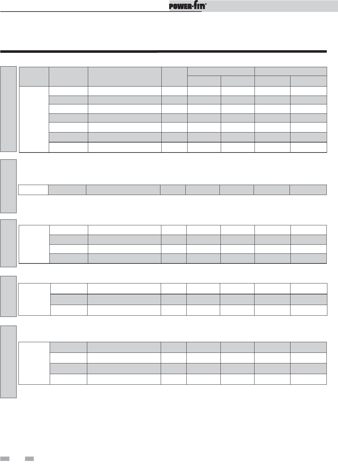
Parameter table
MMEENNUUSSUUBB IITTEEMMDDEESSCCRRIIPPTTIIOONNSSEEEE
PPAAGGEE
UUSSEERR AACCCCEESSSSIINNSSTTAALLLLEERR AACCCCEESSSS
DDIISSPPLLAAYYMMOODDIIFFYYDDIISSPPLLAAYYMMOODDIIFFYY
A
1Heater Model 11 Yes No Yes No
2User Code 11 Yes Yes Yes Yes
3Date and Time 11 Yes Yes Yes Yes
4Software Version 11 Yes No Yes No
5Temperature Units 11 Yes Yes Yes Yes
6Night Setback Temperature 11 Yes Yes Yes Yes
7Night Setback Times 11 Yes Yes Yes Yes
GGEENNEERRAALL
B1SH Set Point User 11 Yes Yes Yes Yes
C
1Hours Running SH 11 Yes No Yes No
2Hours Running DHW 11 Yes No Yes No
3Ignition Attempts 11 Yes No Yes No
4Show Last 10 Errors 11 Yes No Yes No
DDAATTAA
E
1 DHW Tank Set Point 12 Yes Yes Yes Yes
2DHW Boiler Set Point 12 Yes Ye s Yes Yes
3 SH/DHW Switching Time 12 Yes Yes Yes Yes
F
5Outdoor Air Shutdown 12 Yes Yes Yes Yes
6Outdoor Air Shutdown Differential 12 Yes Yes Yes Yes
8Boost Temperature 12 Yes Yes Yes Yes
9Boost Time 12 Yes Yes Yes Yes
TTEEMMPPEERRAATTUURREE
SSEETTTTIINNGG
LLOOGGGGIINNGG
DDHHWW
SSEETTTTIINNGGSS
OOUUTTDDOOOORRAAIIRRRREESSEETT
Table 3A_This table lists SMART SYSTEM control module parameters and where to access them
3 SMART SYSTEM control module

User’s Information Manual
11
Viewable and changeable control parameters
A: General
Heater model
The control will display “LOCHINVAR” as the model
number because the same control is used on several models.
This will be displayed when parameter A1 has been
accessed. This parameter is not changeable.
User code
The User Code allows the user to access and change a
limited number of control parameters. The access code can
be changed by the user or the installer to a code of their
choosing. To change the code, parameter A2 must be
accessed. The default code is 0704. The code can be
changed one digit at a time by using the arrow keys on the
display.
Date and time
The control uses an internal clock for the night setback
feature and for logging of events. For these features to work
correctly, the clock must be set when the unit is first
installed or any time the unit has been powered off for more
than 30 days. To set the clock, parameter A3 must be
accessed. The date and time are displayed as “YY:MM:DD
W hh:mm”. YY = year, MM = month, DD = date, W = day
(1 = Monday, 2 = Tuesday, etc.), hh = hour (24 hour time;
2:00 PM = 14:00), mm = minutes.
Night setback temperature
Once the internal clock has been set correctly, the night setback
feature can be used to program a lower water temperature set
point for space heating or tank. This parameter can be changed
by the user or the installer by accessing parameter A6.The
temperature range for this parameter is 32°F (0°C) to 140°F
(60°C). The feature is turned off with a setting of 32.0°F (0°C).
The default value is 32.0°F (0°C).
Night setback times
If parameter B6 is set to anything other than 32.0°F (0°C), the
night setback feature becomes active. This will require start and
stop times to be programmed for the days that reduced
temperatures are required. These times can be changed by the
user or the installer by accessing parameter A7. Each day of the
week (Monday through Sunday) will have an on and off time.
Example: Monday ON: 22:30, Tuesday OFF: 6:45. If you wish
to skip a day and have no night setback, leave the on and off
times the same. The default times for each day will be 08:00
(OFF) and 18:00 (ON).
B: Temperature settings (boiler only)
SH Set point user
The SH set point user sets the water temperature set point for
fixed operation or the maximum temperature set point when
the outdoor air sensor is used. This parameter can be changed
by the user or the installer by accessing parameter B1.The
temperature range of this parameter is 60°F (15°C) to 230°F
(110°C). The default value is 120°F (49°C).
C: Data logging
Hours running SH
The hours running SH parameter shows the total number of
hours the unit has been in the SH firing position. This
parameter can be viewed by the user and the installer by
accessing parameter C1.
Hours running DHW
The hours running DHW parameter shows the total number of
hours the unit has been in the DHW firing position. This
parameter can be viewed by the user and the installer by
accessing parameter C2.
Ignition attempts
The ignition attempts parameter shows the total number of
times the unit has attempted to fire. This parameter can be
viewed by the user and the installer by accessing parameter C3.
Show last 10 errors
The control will log the 10 most current errors with the date and
time the error occurred. This parameter can be viewed by the
user and the installer by accessing parameter C4.
CAUTION Before changing parameters, note the
settings so that the unit can be returned
to its original operating parameters.
3 SMART SYSTEM control module (continued)
NOTICE The internal clock does not adjust for
Daylight Savings Time and therefore,
will require a manual adjustment.
Software version
The software version allows the user to view the software
version in use by the control. This software controls the
operation of the unit. When a new software version
becomes available, the existing control can be replaced with
a new control to update the software.
Temperature units
The control can be configured to display temperature in
either °C or °F. This parameter can be changed by the user
or the installer by accessing parameter A5. The default is °F.

User’s Information Manual
12
3 SMART SYSTEM control module
E: DHW settings
DHW tank set point
When a temperature sensor is installed in the DHW tank, the
DHW tank set point sets the target temperature of the water in
the tank. The user or installer can adjust this set point by
accessing parameter E1. The temperature range of this
parameter is 60°F (15°C) to 190°F (88°C). The default value is
120°F (49°C).
DHW boiler set point (boiler only)
When a DHW call for heat becomes active, the control will use
the DHW boiler set point to determine the firing rate of the unit
based on the actual outlet water temperature. This parameter
can be changed by the installer by accessing parameter E2.The
temperature range of this parameter is 60°F (15°C) to 200°F
(93°C). The default value is 180°F (82°C).
SH/DHW switching time (boiler only)
The SH/DHW switching time parameter sets the length of time
the control will stay in DHW Mode when a space heating (SH)
call has been received. After this time period has expired the
control will revert to SH Mode. If a DHW call is still active the
timer will reset. After the time period has expired the control
will revert back to DHW Mode. This will continue until one of
the demands has been satisfied. This parameter can be changed
by the installer by accessing parameter E3. The time range of
this parameter is 10 minutes to 240 minutes. The default value
is 30 minutes.
F: Outdoor air reset (boiler only)
Outdoor air shutdown
When the outdoor temperature rises above this point, the
control will block all SH demands (DHW demands will still be
active). This parameter can be changed by the user or the
installer by accessing parameter F5. The temperature range of
this parameter is 0°F (-18°C) to 120°F (49°C). The default value
is 80°F (27°C).
Outdoor air shutdown differential
The outdoor air shutdown differential parameter is the number
of degrees below parameter F5 the outdoor air temperature
must go before the unit will respond to a SH demand. This
parameter can be changed by the user or the installer by
accessing parameter F6. The temperature range of this
parameter is 0°F (0°C) to 90°F (50°C). The default value is 10°F
(5°C).
Boost temperature
If a SH demand lasts longer than the programmed time delay
setting (F9) and there have been no DHW demands, the control
will increase the water temperature set point by the amount in
this parameter. If the SH demand continues through another
time period, the set point will be increased again. This will
continue until either the SH demand ends, a maximum of 20
increases has occurred, or the maximum set point has been
reached. Once the SH demand has been satisfied the set point
will revert back to its calculated setting. The boost temperature
can be changed by the installer by accessing parameter F8.The
temperature range of this parameter is 0°F (0°C) to 45°F (25°C).
The default value is 0°F (0°C). This feature will be active if this
parameter is set to anything other than 0°F (0°C).
Boost time
The boost time parameter sets the amount of time that must
elapse with a SH demand before the water temperature set point
will be increased. This parameter can be changed by the installer
by accessing parameter F9. The time range for this parameter is
1 minute to 60 minutes. The default value is 20 minutes.
User’s Information Manual
13
Status display screens
3 SMART SYSTEM control module (continued)
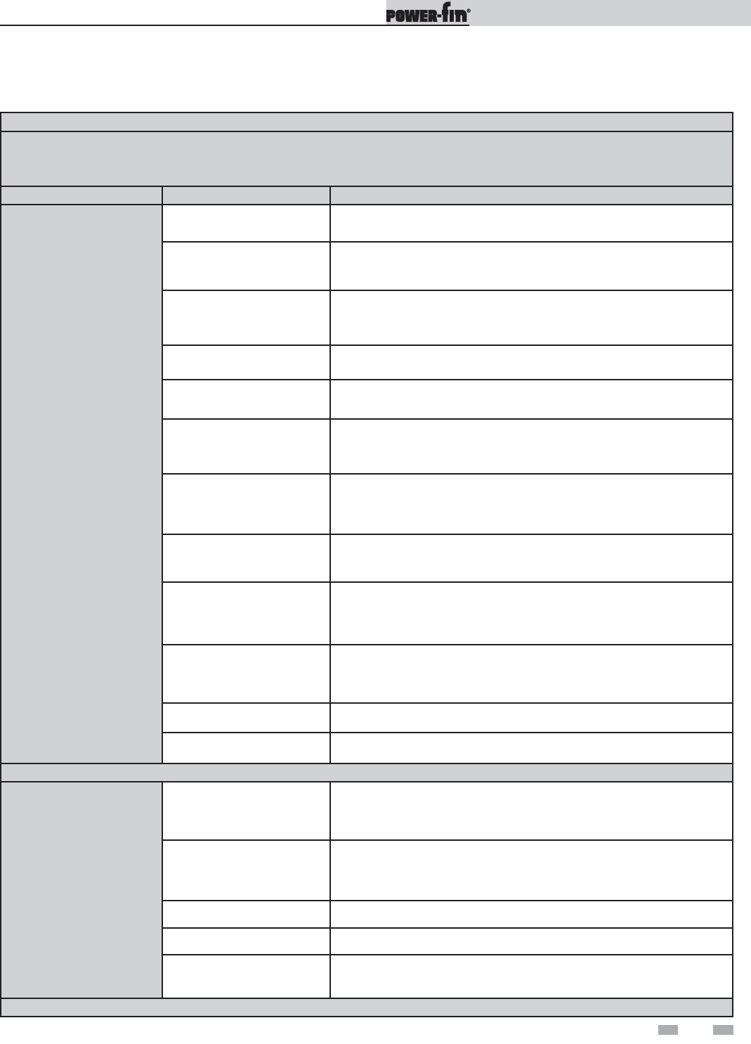
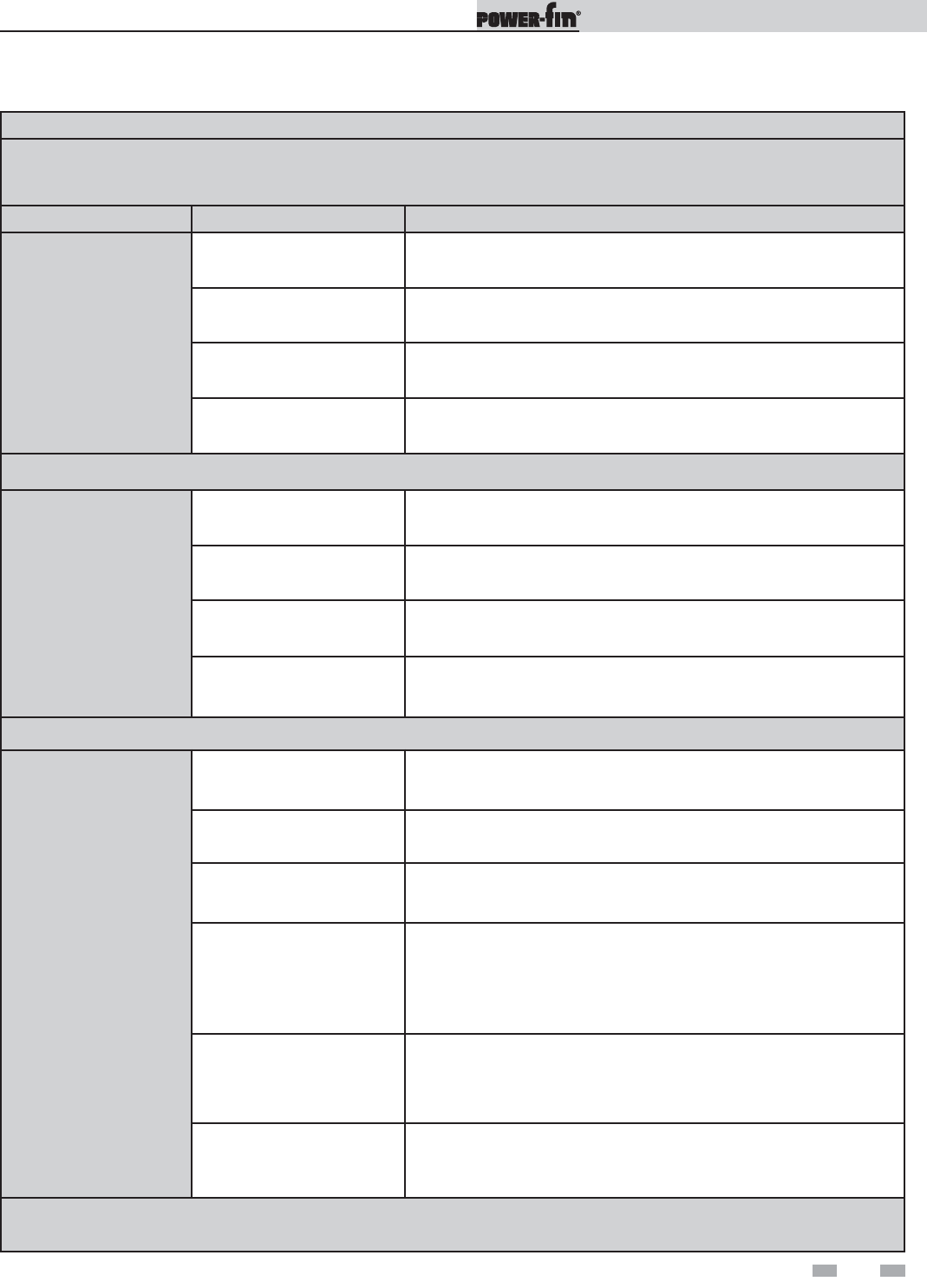
Status Display Screens
By using the Previous/Next (,) arrow keys on the SMART SYSTEM display panel, you can navigate through the nine (9)
display screens. Each screen will contain two (2) viewable items. The following is a description of the individual items and what
they can display:
Screen Display shows: Description
#1
HTR: OFF The unit has been turned OFF by the Enter/Reset button on the
SMART SYSTEM display panel.
Standby The unit has not received a call for heat from a remote thermostat nor
has it received a call for heat from a DHW thermostat.
Set Point Met The unit has met the water temperature set point, but is still receiving
a call for heat from either a remote thermostat or a DHW thermostat.
Prepurge The unit has initiated the 10 second purge and 15 second HSI warm-
up periods on a call for heat.
Ignition The unit has begun a 5 second trial for ignition.
SH***% Rate
DHW***% Rate The unit has fired and is running at the displayed percentage.
Postpurge
The call for heat has been satisfied and the unit runs the fan for an
additional 10 seconds to clear the combustion chamber and vent
system of residual flue products.
Service The unit has been placed in a temporary mode that will allow the unit
to fire for the purpose of combustion analysis.
OUT: ***F(***)
When the outlet sensor has been selected as the control sensor
(default), the control will display the outlet temperature as well as the
set point in parenthesis.
***F
If the outlet sensor has not been selected as the control sensor or a
system supply sensor is connected, only the outlet temperature will be
displayed.
Open The control does not detect the outlet sensor.
Shorted The outlet sensor wires or the sensor itself has become shorted.
Press the Next arrow key on the SMART SYSTEM display to access Screen #2.
#2
IN: ***F
If the inlet sensor has not been selected as the control sensor or a
system return sensor is installed, only the inlet temperature will be
displayed.
***F (***)
When the inlet sensor has been selected as the control sensor, the
control will display the inlet temperature as well as the set point in
parenthesis.
Open The control does not detect the inlet sensor.
Shorted The inlet sensor wires or the sensor itself has become shorted.
RISE: ***F The difference between the inlet temperature and the outlet
temperature.
Press the Next arrow key on the SMART SYSTEM display to access Screen #3.
User’s Information Manual
14
3 SMART SYSTEM control module
Status Display Screens (cont’d)
By using the Previous/Next (,) arrow keys on the SMART SYSTEM display panel, you can navigate through the nine (9)
display screens. Each screen will contain two (2) viewable items. The following is a description of the individual items and what
they can display:
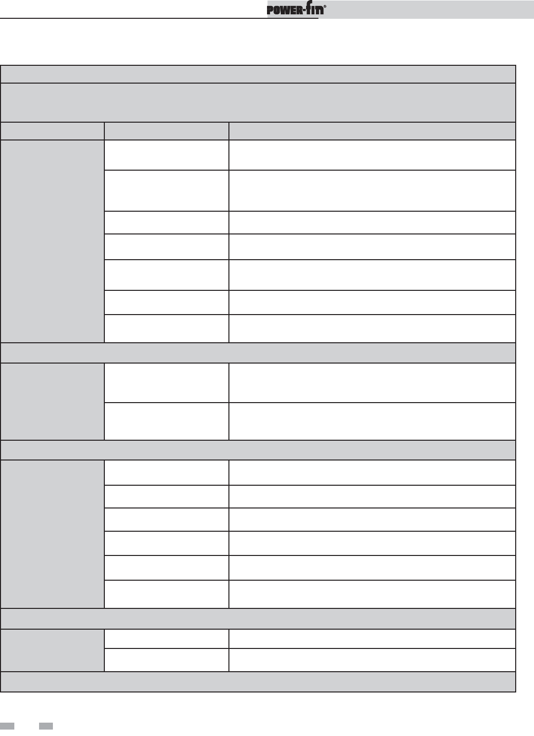
Screen Display shows: Description
#3
SYS: ***F If the system supply sensor has not been selected as the control sensor,
only the system temperature will be displayed.
***F (***)
When the system supply sensor has been selected as the control sensor,
the control will display the system temperature as well as the set point
in parenthesis.
Open The control does not detect the system supply sensor.
Shorted The system supply sensor wires or the sensor itself has become
shorted.
OUTDOOR: ***F The control will display the outdoor air temperature as sensed by the
outdoor air sensor.
Open The control does not detect the outdoor air sensor.
Shorted The outdoor air sensor wires or the sensor itself has become grounded.
Press the Next arrow key on the SMART SYSTEM display to access Screen #4.
#4
SYSRT: ***
The control will display the system return temperature if the system
return sensor is connected. If not connected, the display will skip this
screen and display screen #5.
VALVE: ***% The control will display the position of the 3-way valve; 100% indicates
that no outlet water is being bypassed into the inlet.
Press the Next arrow key on the SMART SYSTEM display to access Screen #5.
#5
FLUE: ***F The control will display the flue temperature.
Open The control does not detect the flue sensor.
Shorted The flue sensor wires or the sensor itself has become shorted.
AUX: ***F The control will display the temperature.
Open The control does not detect the auxiliary sensor.
Shorted The auxiliary sensor wires or the sensor itself has become shorted.
Press the Next arrow key on the SMART SYSTEM display to access Screen #6.
#6
FAN SPD: ****RPM The control will display the actual fan motor RPM.
FLAME SIG: **.*uA The control will display the flame signal in dc microamps.
Press the Next arrow key on the SMART SYSTEM display to access Screen #7.
User’s Information Manual
15
3 SMART SYSTEM control module (continued)
Status Display Screens (cont’d)
By using the Previous/Next (,) arrow keys on the SMART SYSTEM display panel, you can navigate through the nine (9)
display screens. Each screen will contain two (2) viewable items. The following is a description of the individual items and what
they can display:
Screen Display shows: Description
#7
SH CFH: OFF The control has not received a call for heat from a SH remote
thermostat.
ON The control has received a call for heat from a SH remote thermostat.
DHW CFH: OFF The control has not received a call for heat from a tank sensor or tank
thermostat.
ON The control has received a call for heat from a tank sensor or tank
thermostat.
Press the Next arrow key on the SMART SYSTEM display to access Screen #8.
#8
DHW PUMP: OFF The control has not received a DHW call for heat and has not powered
the DHW pump.
ON The control has received a DHW call for heat and has powered the
DHW pump.
Delay The DHW call for heat has been satisfied and the DHW pump is
running for a fixed time to remove any residual heat.
0-10V IN: **.VDC The control will display a 0-10 VDC signal received from a Building
Management System (BMS) connected to the unit.
Press the Next arrow key on the SMART SYSTEM display to access Screen #9.
#9
SYS PUMP: OFF The control has not received a call for heat from a remote thermostat
and has not powered the system pump.
ON The control has received a call for heat from a remote thermostat and
has powered the system pump.
Delay The system call for heat has been satisfied and the system pump is
running for a fixed time to remove any residual heat.
BLR PUMP: OFF
The control has either not received a call for heat from a remote
thermostat, a remote thermostat is not connected to the unit and the
water temperature has not dropped below the temperature set point of
the control to initiate a call for heat, or the control has received a DHW
call for heat from a DHW thermostat.
ON
The control has received a call for heat from a remote thermostat or a
remote thermostat is not connected and the water temperature has
dropped below the temperature set point of the control to initiate a call
for heat.
Delay The call for heat has been satisfied and the boiler pump is running for
a fixed time to remove any residual heat.
Press the Next arrow key on the SMART SYSTEM display to roll back to Screen #1. At any point if you wish to access an earlier
screen, press the Previous arrow key on the SMART SYSTEM display.

Revision Notes: Revision B (PBX-PFX-USER-Rev B)
reflects the addition of Models 502 - 1302 to the manual.
PBX-PFX-USER-Rev B
CP-2M-8/07
