Locks 80 0180 219_E 3890 Removable Mullion Installation Instructions Inst
User Manual: Locks 3890 Removable Mullion Installation Instructions Mayflower Sales - Adams Rite
Open the PDF directly: View PDF ![]() .
.
Page Count: 1
www.adamsrite.com
Phone: 800-626-7590
800-872-3267
Fax: 866-582-4641
800-232-7329
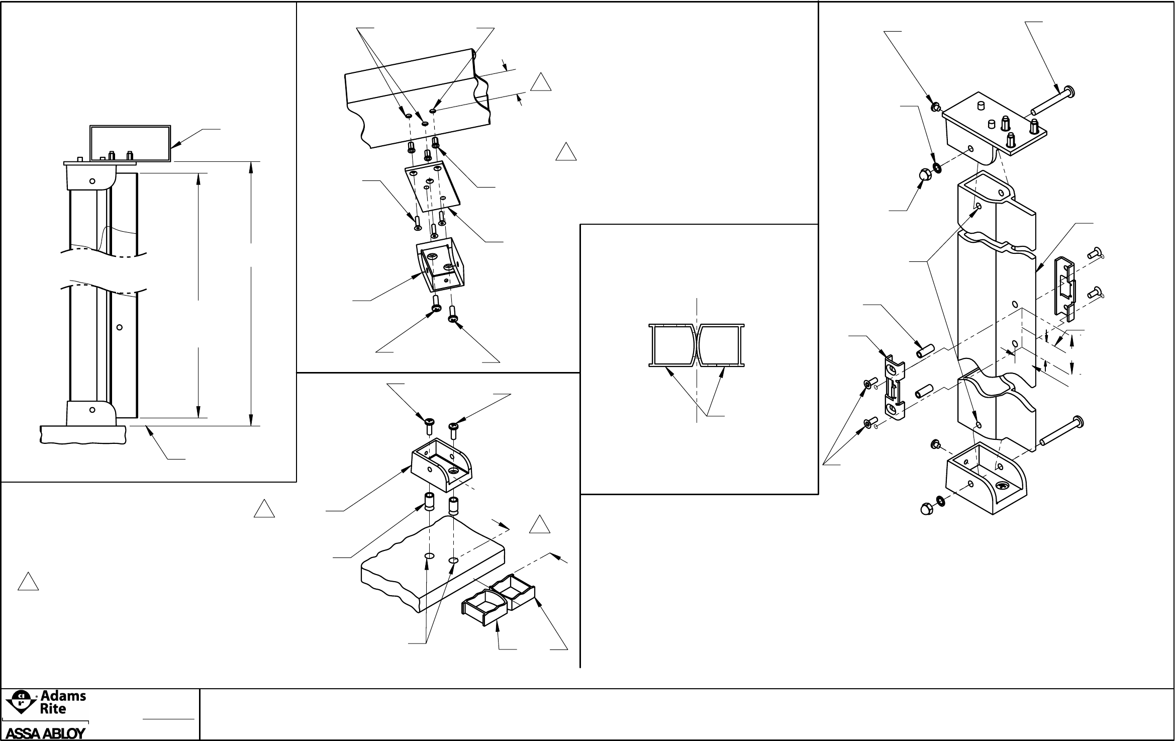
2 1/4"
STEP 2
TOP
FITTING
10-32 RIVNUTS
MOUNTING
PLATE
10-32 X 3/4"
FLAT HEAD
CAP SCREW
(SUPPLIED W/ RIVNUT
INSTALLATION KIT)
MULLION LENGTH
1 1/8" LESS THAN
DOOR OPENING
HEIGHT
DOOR OPENING
HEIGHT
STEP 1
* Measure door opening height from finished floor
to bottom of header.
* Subtract 1 1/8" from door opening dimension
to get length of mullion.
* Measure and cut mullion to size.
FINISHED FLOOR LINE
OUTER SIDE
2"
STEP 3
* Use the bottom fitting as a template
and place it on the floor against the doors
lining up on centerlines.
The bottom fitting is in line with the top fitting.
* Mark and drill two 1/2" dia. holes by 7/8" deep.
* Insert two 1/2" dia. zinc anchors and
mount bottom fitting with two 1/4-20 x 3/4"
pan head mach. screw.
BOTTOM
FITTING
1/4-20
ANCHORS
2 PLCS
1
C
L
C
L
2
C
L
FIG. 1
DOOR
(SECTION VIEW)
1"
For G88
5/8" For 8800
2"
1/4-20 X 3/8"
ACORN NUT
2 PLCS
1/4-20 X 2 1/4"
PAN HEAD SCREW
2 PLCS
WASHER- 1/4
2 PLCS
MULLION
KNURLED
SPACER
2 PLCS
STRIKE
2 PLCS
10-32 X 1/4"
PAN HEAD SCREW
2 PLCS
CENTERLINE
OF PUSHBAR
ON THE DOOR
Ø 17/64"
HOLE
1"
* Use mounting plate as a template to drill
three 1/4" dia.holes for 10-32 rivnuts
lining up centerlines as shown in fig. 1.
* Install mounting plate with three 10-32 x 3/4"
flat head screws.
* Install top fitting on mounting plate using two
1/4-20 x 3/4" pan head machine screws.
1/4-20 x 3/4"
PAN HEAD SCREW
DRILL 1/2" DIA. HOLES
X 7/8" DEEP
DRILL 1/4" DIA. HOLES
1/4-20 X 3/4"
PAN HEAD SCREW
10-32 X 1/2"
FLAT HD. SCR.
4 PLCS
STEP 4
* Slide mullion into top and bottom fittings.
* Drill two 17/64" dia. holes through mullion
using top and bottom fitting holes as guide.
* Insert 1/4 -20 x 2 1/4" pan head screw through
holes in fittings and mullion.
* Slip toothed washer onto screws and secure
with 1/4-20 x 3/8" acorn nuts.
* Install & tighten the two10-32 x 1/4" pan head
screws into the rear of both fittings to stabilize
the mullion.
* To install the strikes, drill two 9/32" holes through
mullion at the pushbar centerline and insert
knurled spacers.
* Mount the strikes to the mullion using four
10-32 X 1/2" flat head cap screws.
1
2
This dimension is used when the door is flush
with the outside of the header. If this is not the
case add the distance that the door is moved
inward from the face of the header to this
dimension.
2
DOOR
OUTER SIDE
OF HEADER
Page of
11
3890 REMOVABLE MULLION FPR ALUMINUM DOORS
Rev.
Appvd: MP
Date:
ECN: 11955C
Date: 07-19-12
E
80-0180-219
07-10-12
