LogiTag Systems 1149466 4 channel RFID reader with CAN bus User Manual
LogiTag Systems Ltd. 4 channel RFID reader with CAN bus Users Manual
UserManual.wiki
>
LogiTag Systems
>
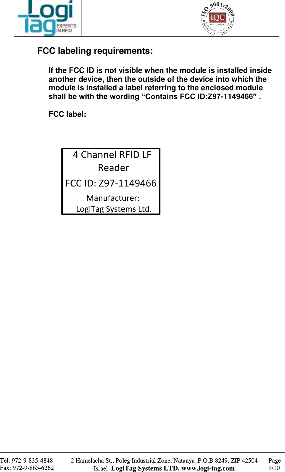
1149466 User Manual
>
Users Manual
Contents
1.
Users Manual
2.
Users manual
Users Manual
Navigation menu
Upload a User Manual
Namespaces
Wiki Guide
HTML
PDF
Info
Views
User Manual
Discussion / Help
Navigation