Loopcomm Technology LP-8186C 54Mbps Wireless AP Router User Manual User s Manual of WLAN Broadband router
Loopcomm Technology,.Inc. 54Mbps Wireless AP Router User s Manual of WLAN Broadband router
UserManual.wiki
>
Loopcomm Technology
>
LP 8186C User Manual
User Manual
Navigation menu
Upload a User Manual
Namespaces
Wiki Guide
HTML
PDF
Info
Views
User Manual
Discussion / Help
Navigation
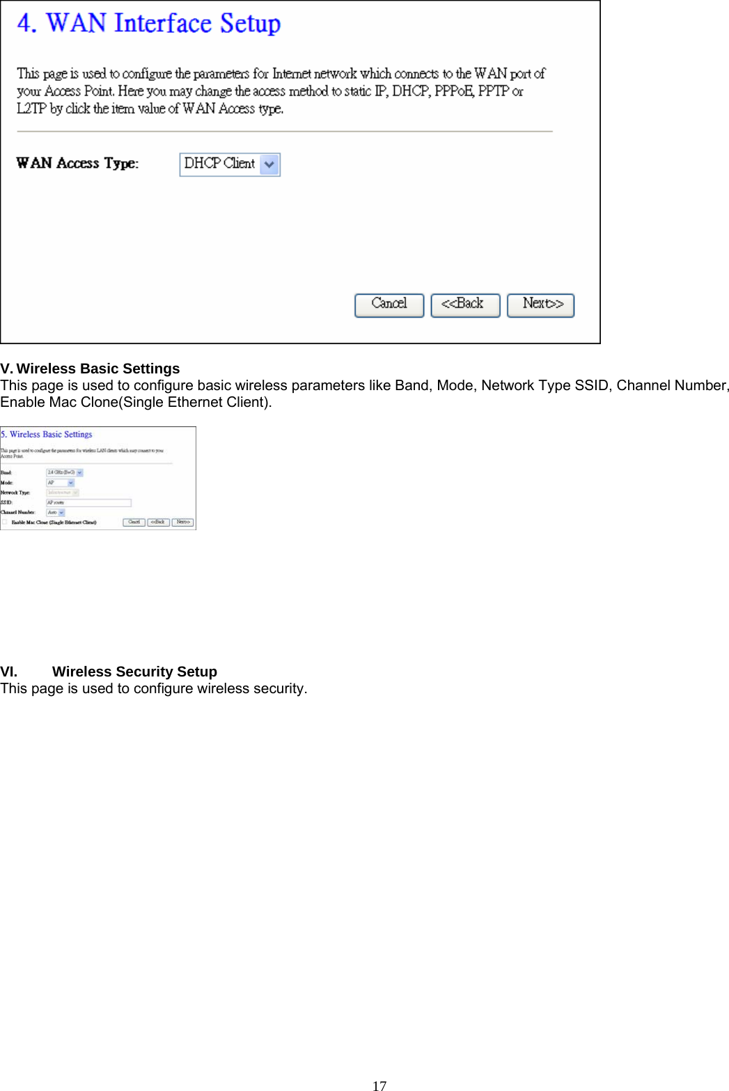
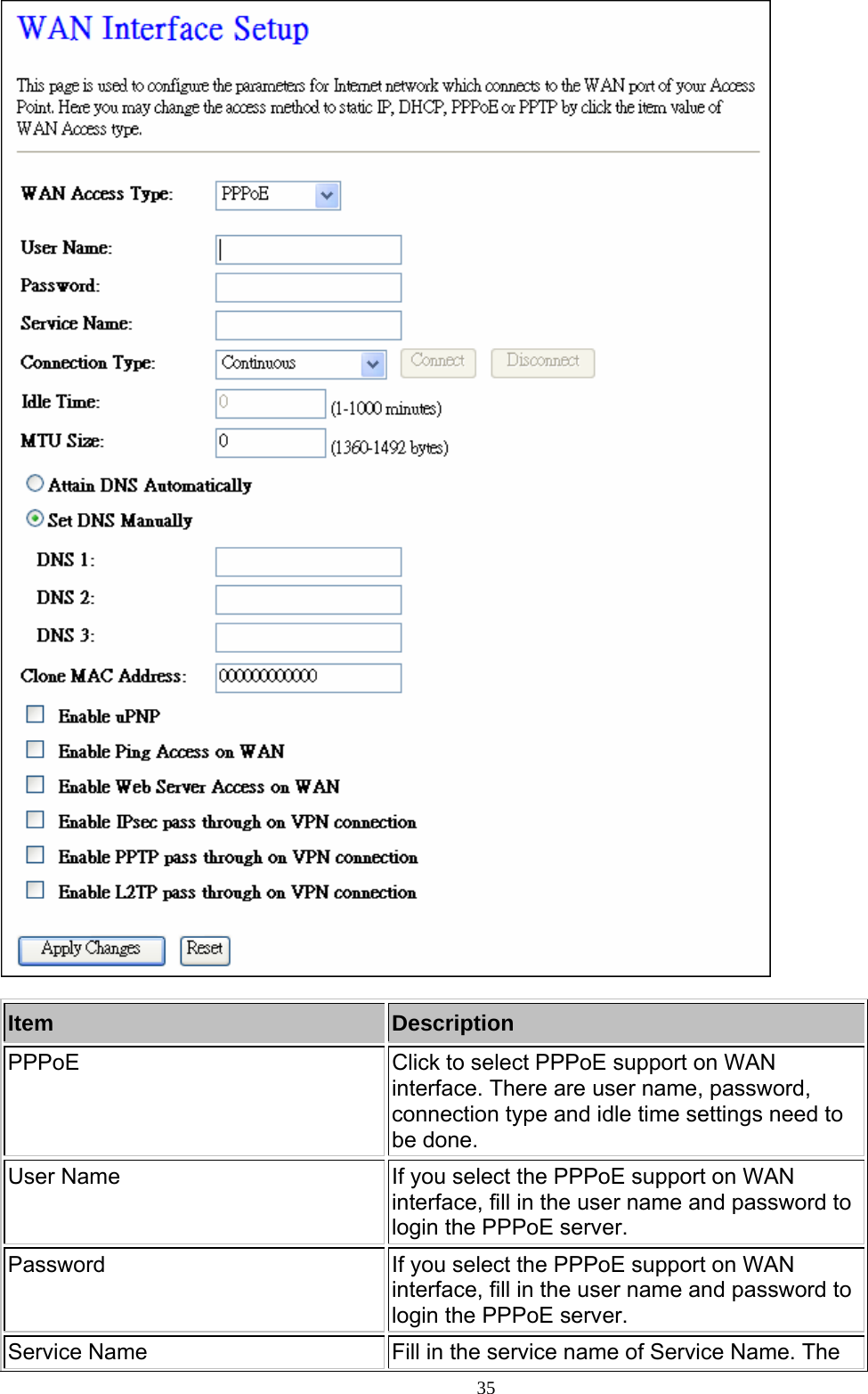
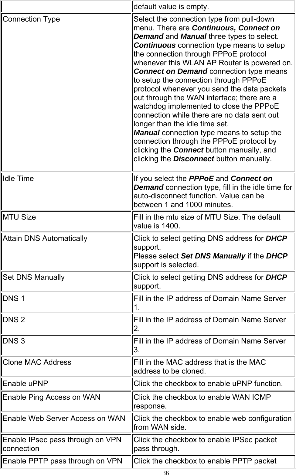
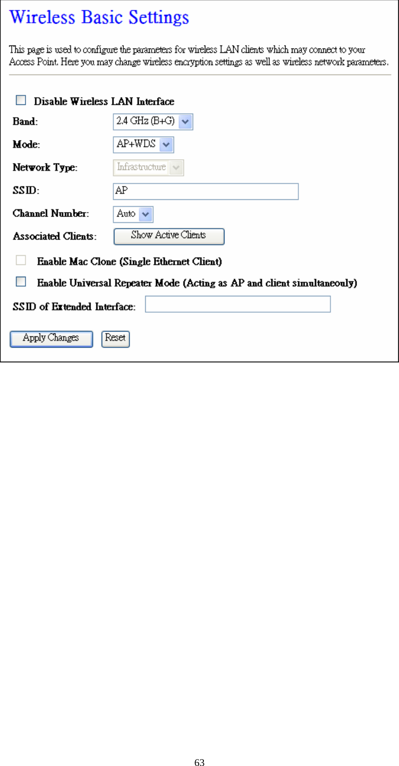
![Item Description Disable Wireless LAN Interface Click on to disable the wireless LAN data transmission. Band Click to select 2.4GHz(B) / 2.4GHz(G) / 2.4GHz(B+G) Mode Click to select the WLAN AP / Client / WDS / AP+WDS wireless mode. Network Type While Mode is selected to be Client. Click to select the network type infrastructure or Ad hoc. SSID It is the wireless network name. The SSID can be 32 bytes long. Channel Number Select the wireless communication channel from pull-down menu. Data Rate Select the transmission data rate from pull-down menu.Data rate can be auto-select, 1M to 54Mbps or MCS. Associated Clients Click the Show Active Clients button to open Active Wireless Client Table that shows the MAC address, transmit-packet, receive-packet and transmission-rate for each associated wireless client. Enable Mac Clone (Single Ethernet Client) Take Laptop NIC MAC address as wireless client MAC address. [Client Mode only] SSID of Extended Click to enable Universal Repeater Mode Interface Assign SSID when enables Universal Repeater Mode. Apply Changes Click the Apply Changes button to complete the new configuration setting. 20](https://usermanual.wiki/Loopcomm-Technology/LP-8186C/User-Guide-1175066-Page-21.png)
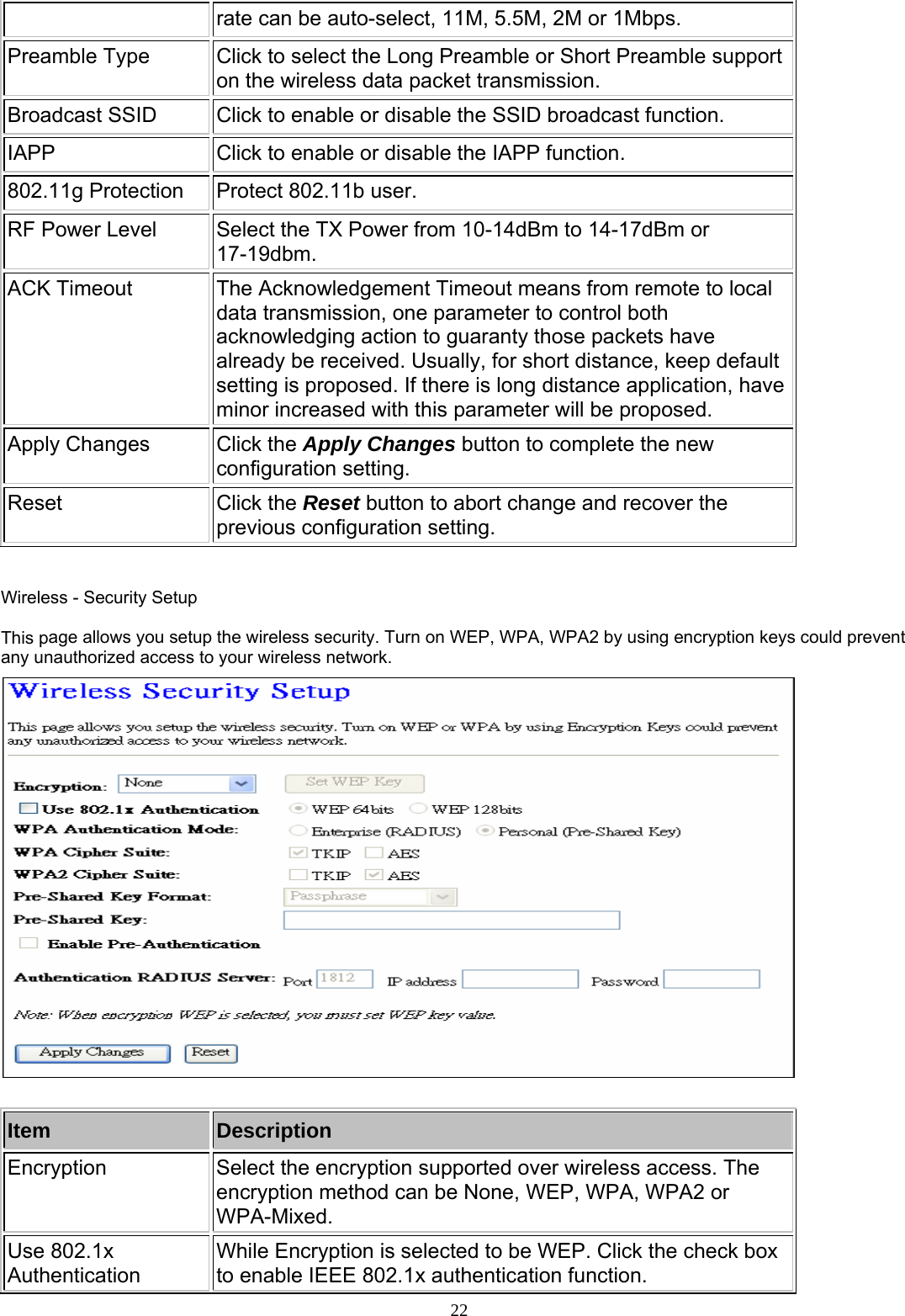
![23WPA Authentication Mode While Encryption is selected to be WPA. Click to select the WPA Authentication Mode with Enterprise (RADIUS) or Personal (Pre-Shared Key). WPA Cipher Suite Select the Cipher Suite for WPA encryption. WPA2 Cipher Suite Select the Cipher Suite for WPA2 encryption. Pre-Shared Key Format While Encryption is selected to be WPA. Select the Pre-shared key format from the pull-down menu. The format can be Passphrase or Hex (64 characters). [WPA, Personal(Pre-Shared Key) only] Pre-Shared Key Fill in the key value. [WPA, Personal(Pre-Shared Key) only] Enable Pre-Authentication Click to enable Pre-Authentication. [WPA2/WPA2 Mixed only, Enterprise only] Authentication RADIUS Server Set the IP address, port and login password information of authentication RADIUS sever. Apply Changes Click the Apply Changes button to complete the new configuration setting. Reset Click the Reset button to abort change and recover the previous configuration setting.](https://usermanual.wiki/Loopcomm-Technology/LP-8186C/User-Guide-1175066-Page-24.png)
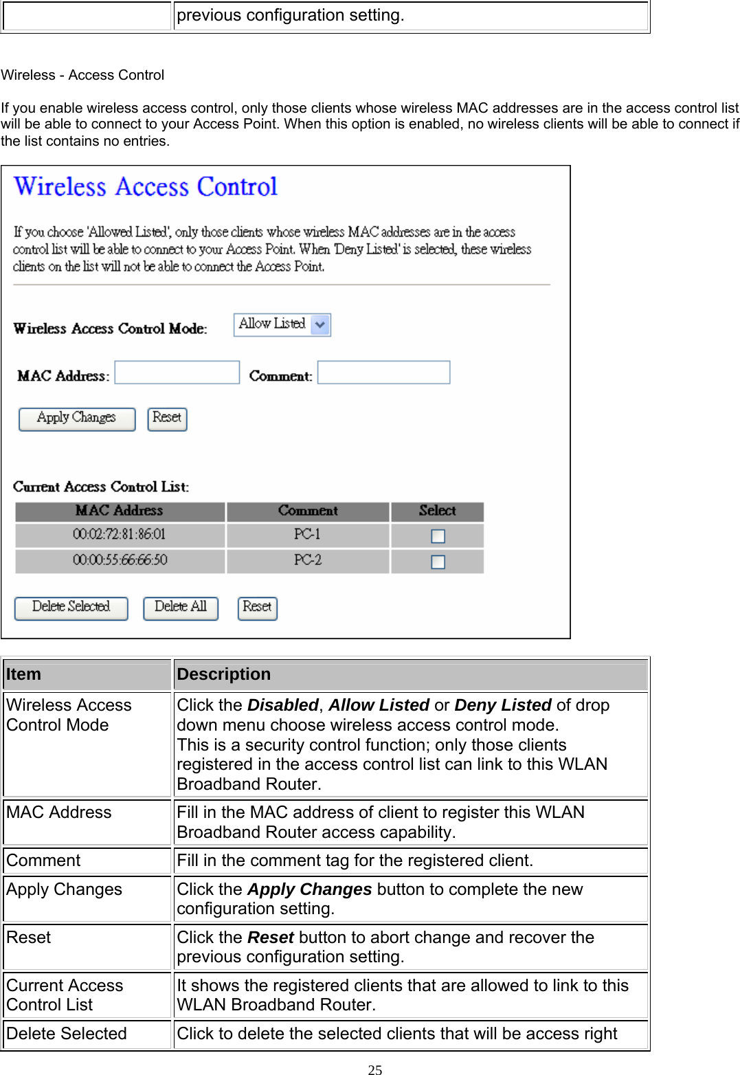
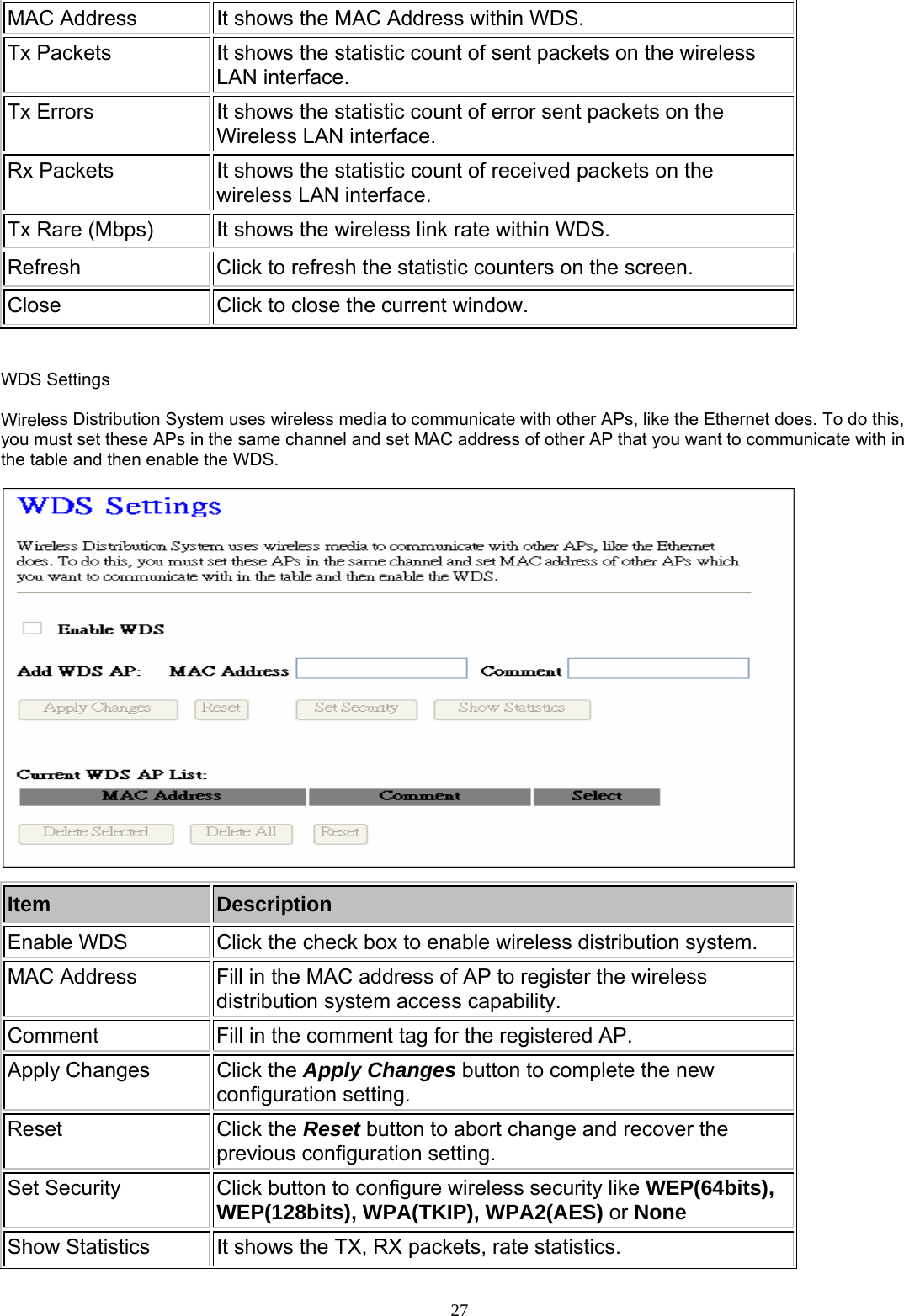
![removed from this WLAN Broadband Router. Delete All Click to delete all the registered clients from the access allowed list. Reset Click the Reset button to abort change and recover the previous configuration setting. WDS Security Setup Requirement: Set [Wireless]->[Basic Settings]->[Mode]->AP+WDS This page is used to configure the wireless security between APs. WDS AP Table This page is used to show WDS statistics. Item Description 26](https://usermanual.wiki/Loopcomm-Technology/LP-8186C/User-Guide-1175066-Page-27.png)
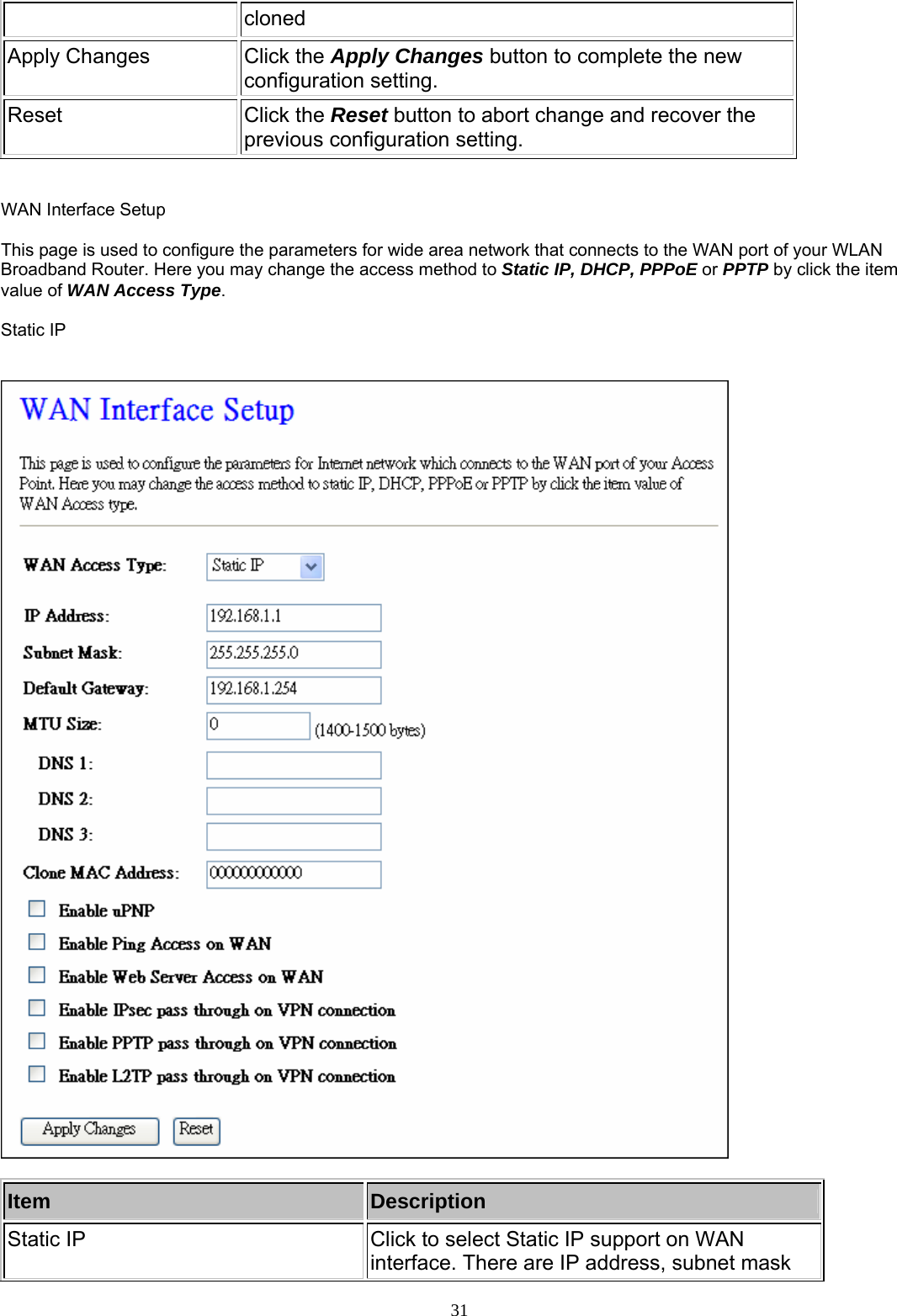
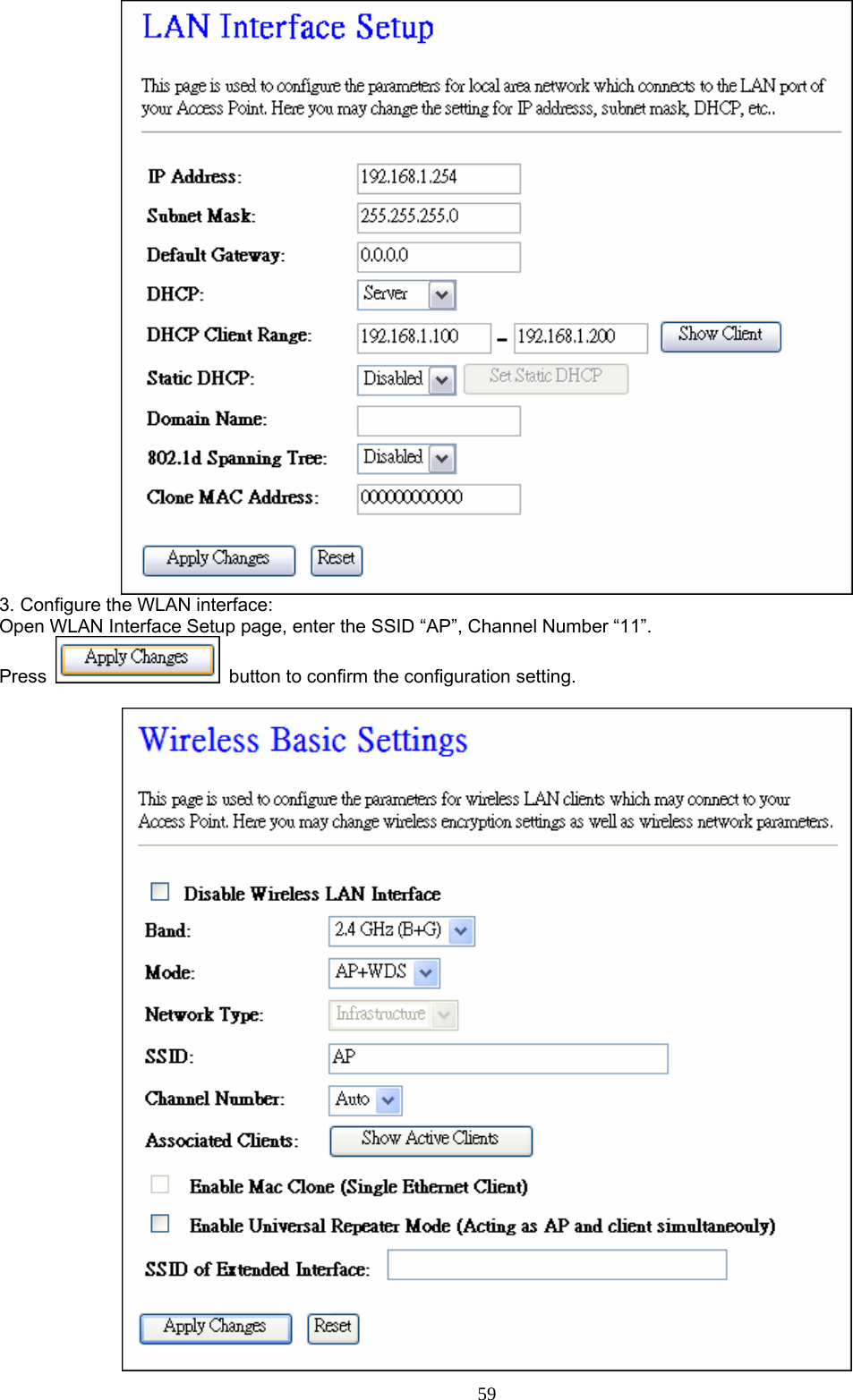
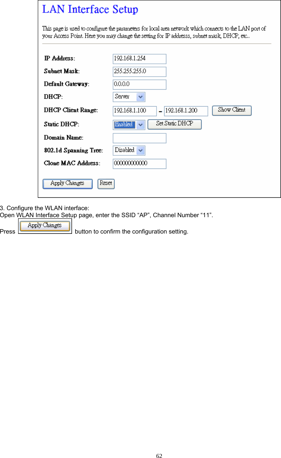
![Item Description IP Address Fill in the IP address of LAN interfaces of this WLAN Access Point. Subnet Mask Fill in the subnet mask of LAN interfaces of this WLAN Access Point. Default Gateway Fill in the default gateway for LAN interfaces out going data packets. DHCP Click to select Disabled, Client or Server in different operation mode of wireless Access Point. DHCP Client Range Fill in the start IP address and end IP address to allocate a range of IP addresses; client with DHCP function set will be assigned an IP address from the range. Show Client Click to open the Active DHCP Client Table window that shows the active clients with their assigned IP address, MAC address and time expired information. [Server mode only] Static DHCP Select enable or disable the Static DHCP function from pull-down menu. [Server mode only] Set Static DHCP Manual setup Static DHCP IP address for specific MAC address. [Server mode only] Domain Name Assign Domain Name and dispatch to DHCP clients. It is optional field. 802.1d Spanning Tree Select enable or disable the IEEE 802.1d Spanning Tree function from pull-down menu. Clone MAC Address Fill in the MAC address that is the MAC address to be 30](https://usermanual.wiki/Loopcomm-Technology/LP-8186C/User-Guide-1175066-Page-31.png)