Lorex Technology WL1741 7 inches Security Video Monitor User Manual LW1740 SERIES USER S GUIDE
Lorex Technology Inc. 7 inches Security Video Monitor LW1740 SERIES USER S GUIDE
Users Manual
LW1741SERIES
USER’S GUIDE

LW1741SERIES
USER’S GUIDE
#LX400030; r.16602/16610; en-US iii
Thank you for purchasing this product. Lorex is committed to providing our customers with a high quality,
reliable security solution.
This manual refers to the following models:
LW1741
LW1742
LW1744
For the latest online manual, downloads and product updates, and to learn about our complete line of
accessory products, please visit our website at:
www.lorextechnology.com
WARNING
RISK OF ELECTRIC SHOCK
DO NOT OPEN
WARNING: TO REDUCE THE RICK OF ELECTRIC SHOCK DO NOT REMOVE
COVER. NO USER SERVICABLE PARTS INSIDE.
REFER SERVICING TO QUALIFIED SERVICE PERSONNEL.
The lightning flash with arrowhead symbol, within an equilateral
triangle, is intended to alert the user to the presence of uninsulated
"dangerous voltage" within the product’s enclosure that may be of
sufficient magnitude to constitute a risk of electric shock.
The exclamation point within an equilateral triangle is intended to
alert the user to the presence of important operating and
maintenance (servicing) instructions in the literature accompanying
the appliance.
WARNING: TO PREVENT FIRE OR SHOCK HAZARD, DO NOT EXPOSE THIS UNIT
TO RAIN OR MOISTURE.
CAUTION: TO PREVENT ELECTRIC SHOCK, MATCH WIDE BLADE OF THE PLUG
TO THE WIDE SLOT AND FULLY INSERT.
#LX400030; r.16602/16610; en-US iv

Table of contents
1 Important Safeguards ..........................................................................1
1.1 General Precautions....................................................................1
1.2 Installation.................................................................................1
1.3 Service.....................................................................................3
1.4 Use..........................................................................................3
2 LW1740 Series Features.......................................................................4
3 Getting Started....................................................................................5
4 Installing the Camera(s).......................................................................6
4.1 Installation Tips ..........................................................................6
4.2 Mounting Positions......................................................................6
5 Installing the Receiver..........................................................................9
6 Camera Overview .............................................................................. 12
7 LCD Receiver Overview...................................................................... 13
7.1 Front Panel.............................................................................. 13
7.2 Side Panel............................................................................... 14
7.3 Rear Panel .............................................................................. 14
8 Using the System .............................................................................. 15
8.1 Understanding the On-screen Display ........................................... 15
8.2 Navigating Menu Screen ............................................................ 16
8.3 Viewing Modes......................................................................... 17
8.3.1 Auto Sequence Viewing Mode .......................................... 17
8.3.2 Quad Mode................................................................... 18
8.4 Digital Zoom ............................................................................ 18
8.5 Changing Audio Volume............................................................. 18
9 Setting the Time ................................................................................ 20
10 Recording......................................................................................... 21
10.1 Format Memory........................................................................ 22
10.2 Scheduled Recording ................................................................ 22
10.2.1 Creating a Recording Schedule ......................................... 22
10.2.2 Stopping Scheduled Recording ......................................... 24
10.2.3 Modifying or Disabling a Recording Schedule....................... 24
10.3 Manual Recording..................................................................... 26
10.4 Enabling / Disabling File Overwrite................................................ 26
11 Playback .......................................................................................... 28
11.1 Video Playback ........................................................................ 28
11.2 Viewing Video Directly from the microSD Card ................................ 28
11.2.1 PC .............................................................................. 29
11.2.2 Mac ............................................................................ 29
12 Pairing Additional Cameras ................................................................ 30
13 Technical Specifications..................................................................... 32
13.1 General Specifications ............................................................... 32
13.2 Camera Specifications............................................................... 32
13.3 Receiver Specifications.............................................................. 32
13.4 Dimensions ............................................................................. 33
13.4.1 LCD Receiver................................................................ 33
13.4.2 Camera with Metal Stand ................................................. 33
14 Troubleshooting ................................................................................ 34
15 Frequently Asked Questions............................................................... 35
#LX400030; r.16602/16610; en-US v
Important Safeguards
1
In addition to the careful attention devoted to quality standards in the manufacturing proc-
ess of your product, safety is a major factor in the design of every instrument. However,
safety is your responsibility too. This sheet lists important information that will help to en-
sure your enjoyment and proper use of the product and accessory equipment. Please read
them carefully before operating and using your product.
1.1 General Precautions
1. All warnings and instructions in this manual should be followed.
2. Remove the plug from the outlet before cleaning. Do not use liquid aerosol detergents.
Use a water-dampened cloth for cleaning.
3. Do not use this product in humid or wet places.
4. Keep enough space around the product for ventilation. Slots and openings in the stor-
age cabinet should not be blocked.
5. It is highly recommended to connect the product to a surge protector to protect from
damage caused by electrical surges. It is also recommended to connect the product to
an uninterruptible power supply (UPS), which has an internal battery that will keep the
product running in the event of a power outage.
CAUTION
Maintain electrical safety. Power line operated equipment or accessories connected to this product
should bear the UL listing mark or CSA certification mark on the accessory itself and should not be modi-
fied so as to defeat the safety features. This will help avoid any potential hazard from electrical shock or
fire. If in doubt, contact qualified service personnel.
1.2 Installation
1. Read and Follow Instructions - All the safety and operating instructions should be
read before the product is operated. Follow all operating instructions.
2. Retain Instructions - The safety and operating instructions should be retained for fu-
ture reference.
3. Heed Warnings - Comply with all warnings on the product and in the operating
instructions.
4. Polarization - Do not defeat the safety purpose of the polarized or grounding-type
plug.
A polarized plug has two blades with one wider than the other.
A grounding type plug has two blades and a third grounding prong.
The wide blade or the third prong are provided for your safety.
If the provided plug does not fit into your outlet, consult an electrician for replacement
of the obsolete outlet.
#LX400030; r.16602/16610; en-US 1

Important Safeguards
1
5. Power Sources - This product should be operated only from the type of power source
indicated on the marking label. If you are not sure of the type of power supplied to your
location, consult your video dealer or local power company. For products intended to
operate from battery power, or other sources, refer to the operating instructions.
6. Overloading - Do not overload wall outlets or extension cords as this can result in the
risk of fire or electric shock. Overloaded AC outlets, extension cords, frayed power
cords, damaged or cracked wire insulation, and broken plugs are dangerous. They
may result in a shock or fire hazard. Periodically examine the cord, and if its appear-
ance indicates damage or deteriorated insulation, have it replaced by your service
technician.
7. Power-Cord Protection - Power supply cords should be routed so that they are not
likely to be walked on or pinched by items placed upon or against them. Pay particular
attention to cords at plugs, convenience receptacles, and the point where they exit
from the product.
8. Surge Protectors - It is highly recommended that the product be connected to a
surge protector. Doing so will protect the product from damage caused by power
surges. Surge protectors should bear the UL listing mark or CSA certification mark.
9. Uninterruptible Power Supplies (UPS) - Because this product is designed for con-
tinuous, 24/7 operation, it is recommended that you connect the product to an uninter-
ruptible power supply. An uninterruptible power supply has an internal battery that will
keep the product running in the event of a power outage. Uninterruptible power sup-
plies should bear the UL listing mark or CSA certification mark.
10. Ventilation - Slots and openings in the case are provided for ventilation to ensure reli-
able operation of the product and to protect it from overheating. These openings must
not be blocked or covered. The openings should never be blocked by placing the prod-
uct on a bed, sofa, rug, or other similar surface. This product should never be placed
near or over a radiator or heat register. This product should not be placed in a built-in
installation such as a bookcase or rack unless proper ventilation is provided and the
product manufacturer’s instructions have been followed.
11. Attachments - Do not use attachments unless recommended by the product manu-
facturer as they may cause a hazard.
12. Water and Moisture - Do not use this product near water — for example, near a bath
tub, wash bowl, kitchen sink or laundry tub, in a wet basement, near a swimming pool
and the like.
13. Heat - The product should be situated away from heat sources such as radiators, heat
registers, stoves, or other products (including amplifiers) that produce heat.
14. Accessories - Do not place this product on an unstable cart, stand, tripod, or table.
The product may fall, causing serious damage to the product. Use this product only
with a cart, stand, tripod, bracket, or table recommended by the manufacturer or sold
with the product. Any mounting of the product should follow the manufacturer’s instruc-
tions and use a mounting accessory recommended by the manufacturer.
15. Camera Extension Cables – Check the rating of your extension cable(s) to verify
compliance with your local authority regulations prior to installation.
16. Mounting - The cameras provided with this system should be mounted only as in-
structed in this guide or the instructions that came with your cameras, using the pro-
vided mounting brackets.
#LX400030; r.16602/16610; en-US 2

Important Safeguards
1
17. Camera Installation - Cameras are not intended for submersion in water. Not all cam-
eras can be installed outdoors. Check your camera environmental rating to confirm if
they can be installed outdoors. When installing cameras outdoors, installation in a
sheltered area is required.
1.3 Service
1. Servicing - Do not attempt to service this product yourself, as opening or removing
covers may expose you to dangerous voltage or other hazards. Refer all servicing to
qualified service personnel.
2. Conditions Requiring Service - Unplug this product from the wall outlet and refer
servicing to qualified service personnel under the following conditions:
• When the power supply cord or plug is damaged.
• If liquid has been spilled or objects have fallen into the product.
• If the product has been exposed to rain or water.
• If the product has been dropped or the cabinet has been damaged
• If the product does not operate normally by following the operating instructions. Ad-
just only those controls that are covered by the operating instructions. Improper ad-
justment of other controls may result in damage and will often require extensive
work by a qualified technician to restore the product to its normal operation.
• When the product exhibits a distinct change in performance. This indicates a need
for service.
3. Replacement Parts - When replacement parts are required, have the service techni-
cian verify that the replacements used have the same safety characteristics as the orig-
inal parts. Use of replacements specified by the product manufacturer can prevent fire,
electric shock, or other hazards.
4. Safety Check - Upon completion of any service or repairs to this product, ask the
service technician to perform safety checks recommended by the manufacturer to de-
termine that the product is in safe operating condition.
1.4 Use
1. Cleaning - Unplug the product from the wall outlet before cleaning. Do not use liquid
cleaners or aerosol cleaners. Use a damp cloth for cleaning.
2. Product and Cart Combination - When product is installed on a cart, product and
cart combination should be moved with care. Quick stops, excessive force, and un-
even surfaces may cause the product and cart combination to overturn.
3. Object and Liquid Entry - Never push objects of any kind into this product through
openings as they may touch dangerous voltage points or “short-out” parts that could
result in a fire or electric shock. Never spill liquid of any kind on the product.
4. Lightning - For added protection of this product during a lightning storm, or when it is
left unattended and unused for long periods of time, unplug it from the wall outlet and
disconnect the antenna or cable system. This will prevent damage to the product due
to lightning and power line surges.
#LX400030; r.16602/16610; en-US 3

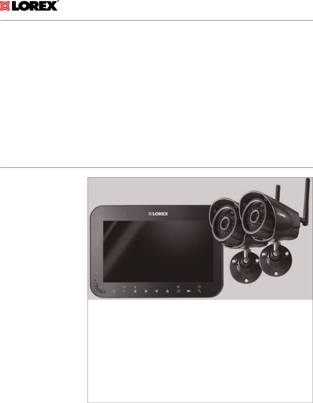
LW1740 Series Features
2
• 7” rechargeable wireless LCD monitor.1
• Weather resistant wireless camera.2
• Manual, motion, and schedule recording.
• Listen-in audio monitoring.3
• Expandable up to 4 cameras.
• 4GB SD card included; 32GB supported.
• Easy to use menu with icons.
• Simple installation. No video cables required.
• Up to XXXXXX days of recording.
• Video motion detection.
• Time and date stamped recordings for easy retrieval.
• Front panel feather touch controls.
• Motorized camera filter provides accurate color reproduction in all lighting conditions.
• Night time viewing up to XXXXXXXft (20m) away in ambient night time lighting condi-
tions and up to XXXXXXXft (14m) away in total darkness.4
• View and record up to 4 cameras at the same time in quad screen.
• Secure wireless signal (FHSS).
• Up to 150ft (50m) indoor / 450ft (150m) outdoor wireless range.5
• Record in real time video.
• 2x Digital Zoom.
Note
1. Up to 3 hours of portable wireless monitoring. For extended monitoring ensure the wireless monitor
is connected to a local power outlet.
2. Wireless cameras require a wired connection to power outlet. Not intended for direct exposure to
rain or snow. For outdoor applications, install under shelter protected from the elements.
3. Audio recording without consent is illegal in certain jurisdictions. Lorex Corporation assumes no li-
ability for use of its products that does not conform with local laws.
4. Stated IR illumination ranges are based on ideal conditions in total darkness and typical outdoor
night time ambient lighting. Actual range and image clarity depends on installation location, viewing
area and light reflection / absorption.
5. Range up to 450ft/150m outdoor, 150ft/50m indoor based on line of sight. Actual range will vary de-
pending on obstructions.
#LX400030; r.16602/16610; en-US 4
Getting Started
3
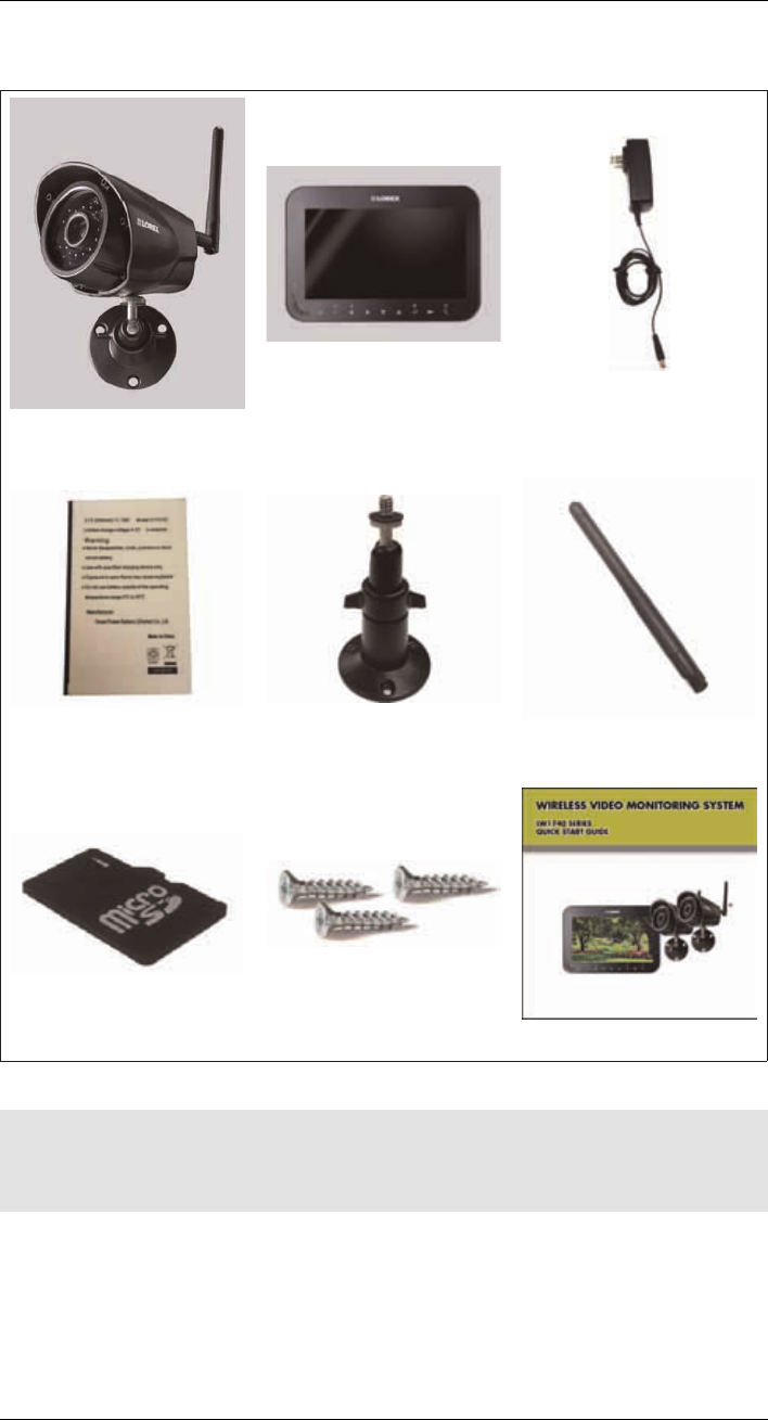
The system includes the following components:
Indoor / outdoor wireless camera
(s)*
7” rechargeable LCD receiver /
recorder
Power adapters for receiver and
camera(s)*
Rechargeable Lithium polymer
battery Camera mounting stand* Wireless antenna for camera
(SMA)*
4GB microSD memory card Mounting kit(s)* Quick Start Guide
* Configuration may vary by model
Note
Camera configuration, memory card size, and the number of accessories may vary by model. Please re-
fer to your package for specific details. Check your package to confirm that you have received the com-
plete system.
#LX400030; r.16602/16610; en-US 5
Installing the Camera(s)
4
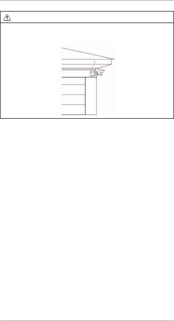
CAUTION
Cameras are suitable for outdoor installation, but are weather resistant, not weatherproof. Cameras are
not intended for direct exposure to rain or snow. For outdoor applications, install under shelter pro-
tected from the elements, such as beneath roof eaves. The diagram below shows an example of an ideal
location for outdoor placement.
4.1 Installation Tips
• Before you install the camera, plan where and how it will be positioned, and where you
will route the cable that connects the camera to the power adapter.
• Before starting permanent installation, check the camera image on the receiver when
camera is positioned in the same place it will be permanently installed.
• It is recommended to ensure a clear line-of-sight between the camera and receiver and
to limit the amount of obstructions, such as walls and tree branches, between the cam-
era and receiver. Walls made of heavy building materials such as brick or concrete will
significantly reduce signal range.
• If the signal will have to pass through a wall, placing the receiver or camera next to a
window will improve the signal strength.
• Do not install the camera pointing out of a window. The nighttime picture will be unus-
able due to reflection from the night vision LED’s.
• The cameras are pre-paired so they work out of the box. Each camera has a channel
number sticker indicating what channel they are paired to. If you have purchased addi-
tional cameras, you will need to pair them to the receiver, see 12 Pairing Additional
Cameras, page 30.
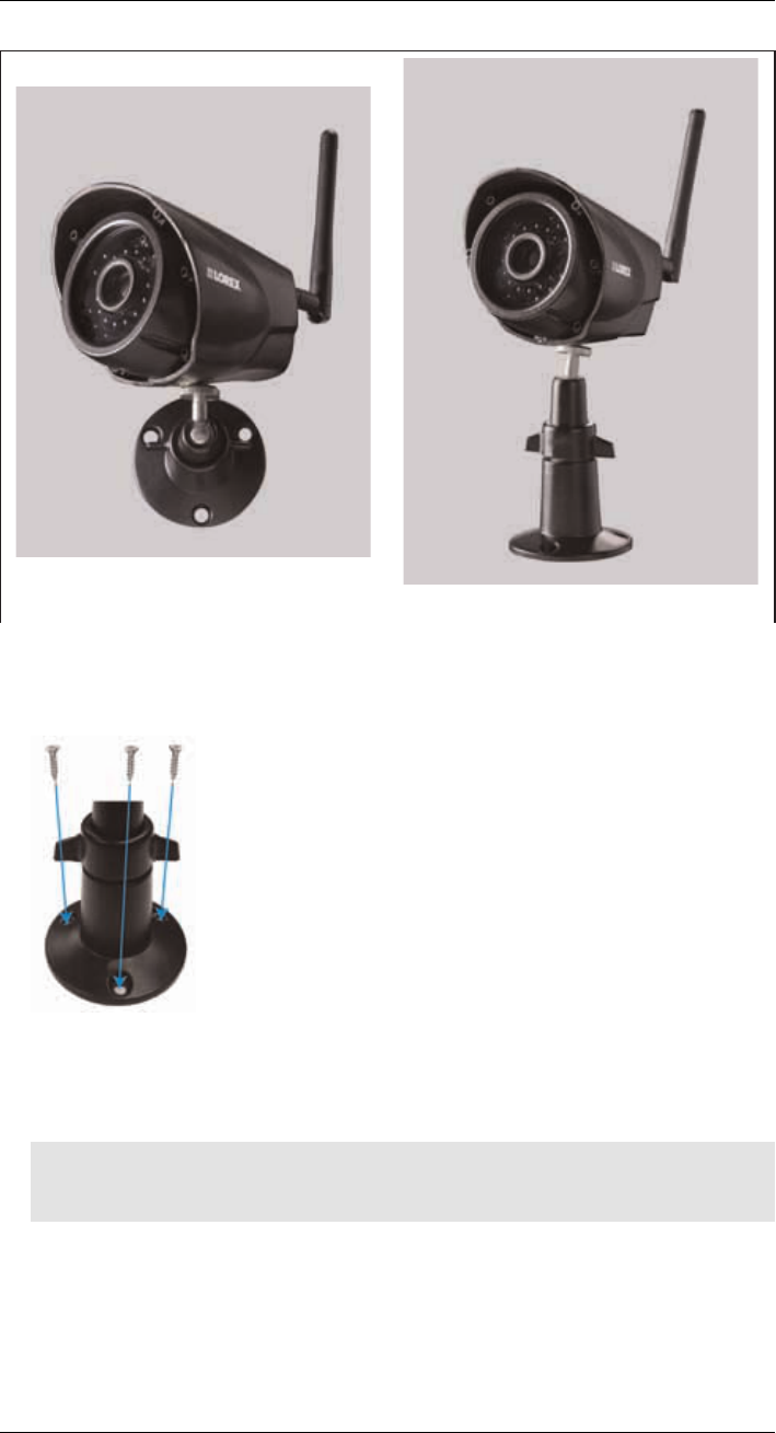
4.2 Mounting Positions
You may mount your cameras on a wall or ceiling. See the images below for recommended
configurations of the camera stand and antenna.
#LX400030; r.16602/16610; en-US 6
Installing the Camera(s)
4
Wall Counter
To install the camera(s):
1. Use the included mounting screws to attach the camera stand(s) to the mounting
surface:
• Mark the positions of the screw holes on the mounting surface with the base of the
mounting stand.
• Drill holes and insert the drywall plugs (included) as needed.
• Firmly attach the camera(s) to the mounting surface using the included screws.
Note
If you run the power cable through the mounting surface, connect power before attaching the camera
to the wall.
2. Attach the camera stand(s) to the camera(s).
#LX400030; r.16602/16610; en-US 7
Installing the Camera(s)
4
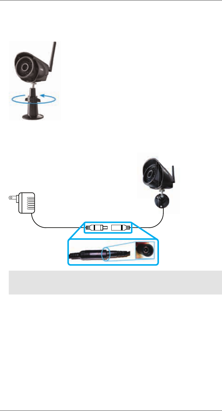
3. Loosen the adjustment ring on the metal camera stand(s) and move the camera to the
desired position. Tighten the adjustment ring when finished, holding the camera firmly
in position.
4. Connect one end of the camera’s power adapter to the camera and the other end to an
electrical outlet or surge protector. Make sure the power connector is fully inserted to
avoid water getting in the plug.
Note
Power cables are only weatherproof when fully inserted at the connection point. Power cables may
not be submerged in water.
5. Remove the protective film from the front of the camera. If the film is not removed, it will
block the built-in microphone and affect the quality of the picture.
#LX400030; r.16602/16610; en-US 8
Installing the Receiver
5
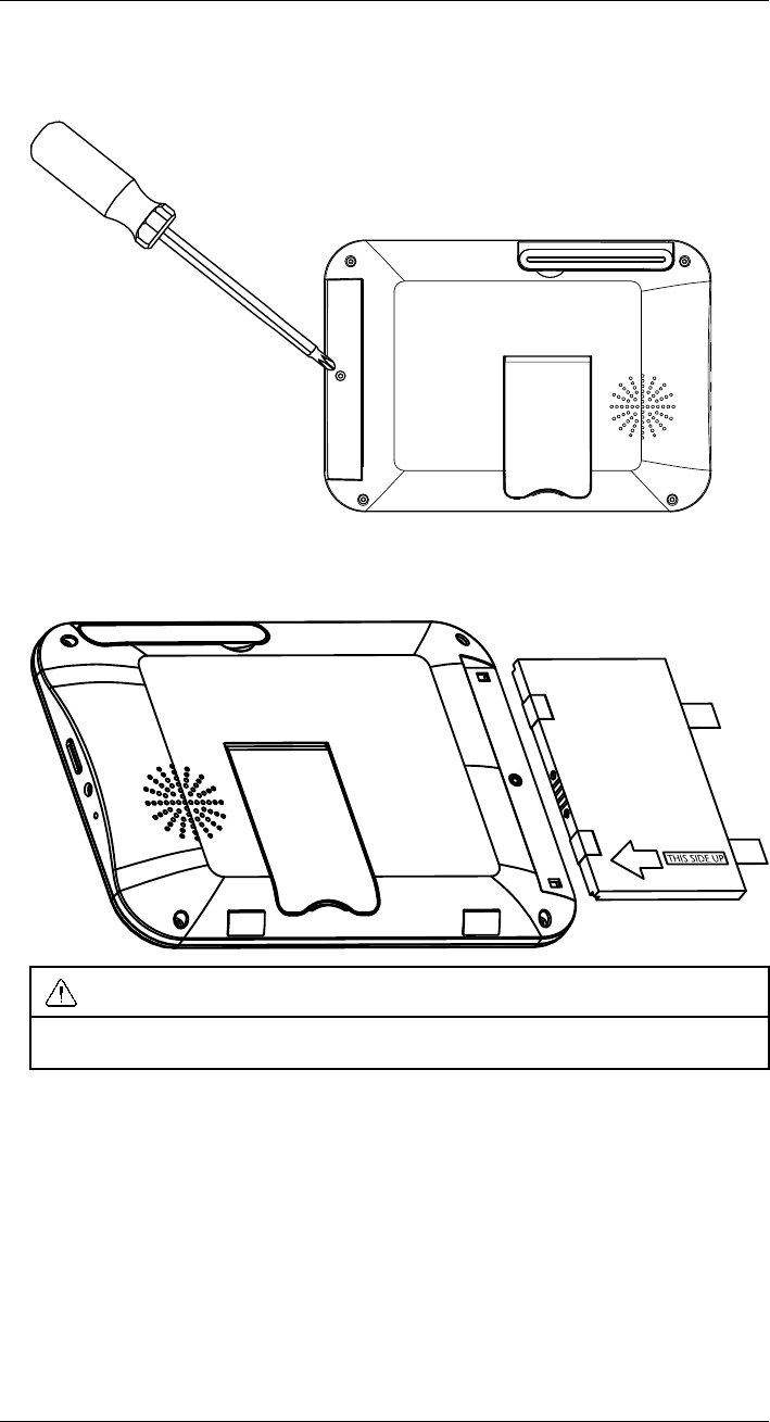
1. Use a Phillips screwdriver (not included) to open the battery compartment on the back
panel.
2. Insert the included battery so the statement "THIS SIDE UP" is visible, and the clear
plastic tabs on the side of the battery face outwards. Replace the battery compartment
cover.
THIS SIDE UP
CAUTION
If you do not plan to use the unit for a prolonged period of time, remove the battery or ensure you
charge it at least once every 3 months.
#LX400030; r.16602/16610; en-US 9
Installing the Receiver
5
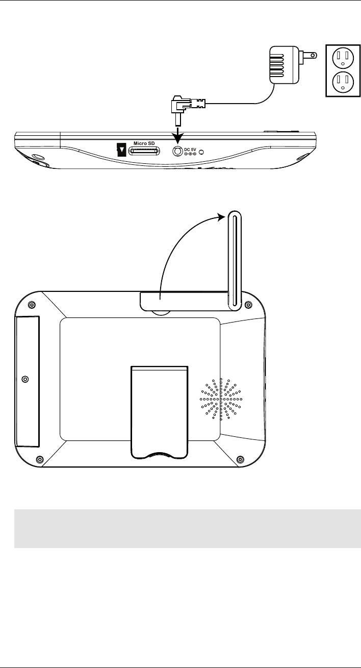
3. Connect the included power adapter to the receiver and to an electrical outlet.
Micro SD
DC 5V
4. Charge the receiver overnight before using for the first time.
5. Pull up the antenna on the back of the LCD receiver.
6. Press and hold the power button on the front panel for 2 seconds. The startup screen
appears, followed by live video from your camera(s).
Note
If one or more cameras do not appear when selected (for example, Camera 2 is plugged in but does
not appear on channel 2), see 12 Pairing Additional Cameras, page 30.
Tips:
• Place the receiver in a location that will have a clear reception to your camera. Try to
maintain line-of-sight and minimize the number of obstructions between the camera
and receiver.
• Adjust the antenna on the receiver as necessary to provide the clearest reception.
#LX400030; r.16602/16610; en-US 10

Camera Overview
6
1
2
3
Pair
4
5
6
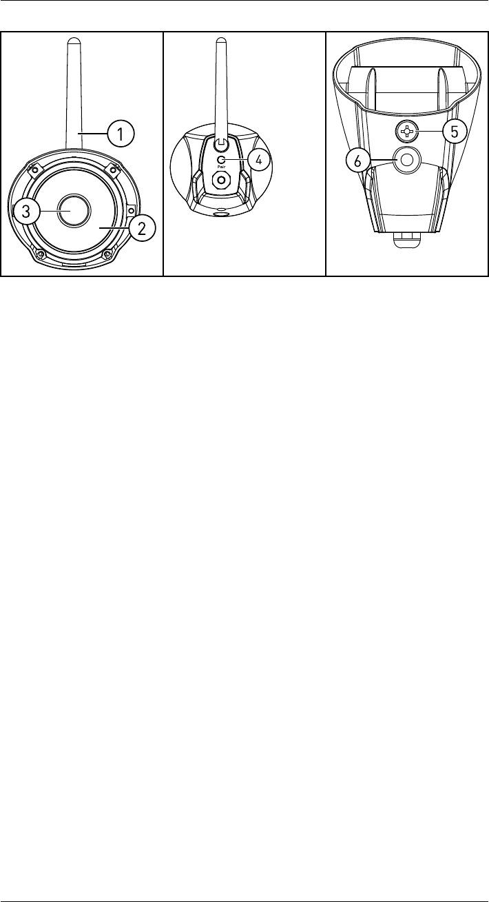
1. Antenna: Removable wireless antenna (SMA)
2. IR LEDs: Night vision IR LEDs.
3. Lens
4. Pair: Press to pair additional cameras to the system. See 12 Pairing Additional Cam-
eras, page 30 for full details.
5. Microphone: Built-in microphone for listen-in audio.
6. Attachment Point: Attach the included metal stand to the camera. See 4 Installing the
Camera(s), page 6 for full details.
#LX400030; r.16602/16610; en-US 12
LCD Receiver Overview
7
7.1 Front Panel
OK
2
3
4
5
6
7
8
9
1
0
1
1
1
2
1
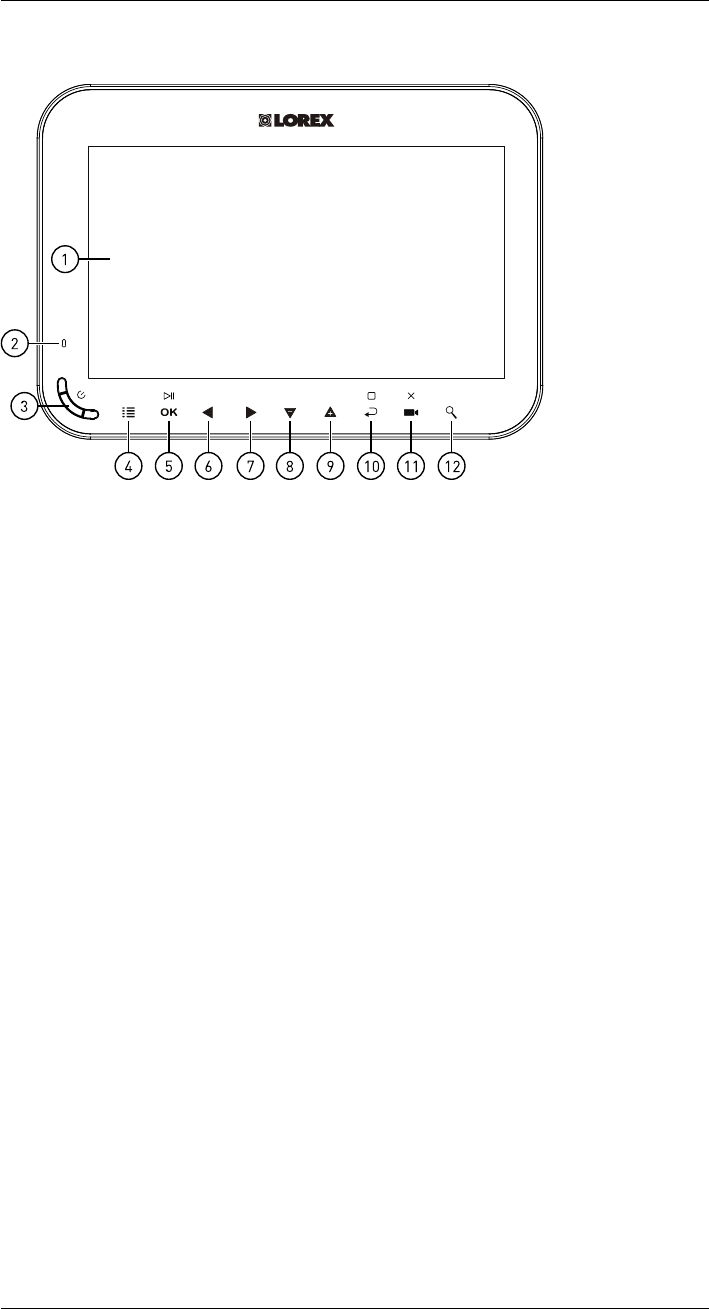
1. LCD Screen
2. Indicator LED: Indicates system status in the following ways:
•Solid green: Indicates that battery life is half-full or greater.
•Solid red: Indicates that the receiver is plugged in and turned off.
•Flashing red: Indicates that the battery is low OR, the receiver is plugged in but the
battery is not inserted.
3. Power Button: Press and hold for 2 seconds to turn the receiver on or off.
4. Menu: Press to enter the system menu.
5. Enter / Play / Pause:
• In menus, press to confirm a selection.
• In live view, press to switch the viewing mode between single channel mode, quad
mode, or scan mode. For more details on viewing modes, see CROSSREF.
• In video playback, press to play / pause video.
6. Left / Rewind: Press to move selection to the left in menus, or press and hold to re-
wind in video playback.
7. Right / Fast-Forward: Press to move selection to the right in menus, or press and hold
to fast-forward in video playback.
8. Down / Decrease Volume: Press to move selection to the down in menus, or to de-
crease volume in live view.
9. Up / Increase Volume: Press to move selection to the up in menus, or to increase vol-
ume in live view.
10. Back / Stop: Press to go back to the previous menu or to stop video playback.
11. Record / Snapshot / Delete:
• Press in live view to begin manually recording video. For full details on manual re-
cording, see CROSSREF.
• Press and hold in live view to take a snapshot. For full details on taking snapshots,
see CROSSREF.
• Press while selecting a snapshot or video in the playback menu to delete the file.
For full details on deleting snapshots, see CROSSREF. For full details on deleting
video recordings, see CROSSREF.
#LX400030; r.16602/16610; en-US 13
LCD Receiver Overview
7
12. Zoom: Press to enter 2x digital zoom.
7.2 Side Panel
Micro S D
DC 5V
2
1
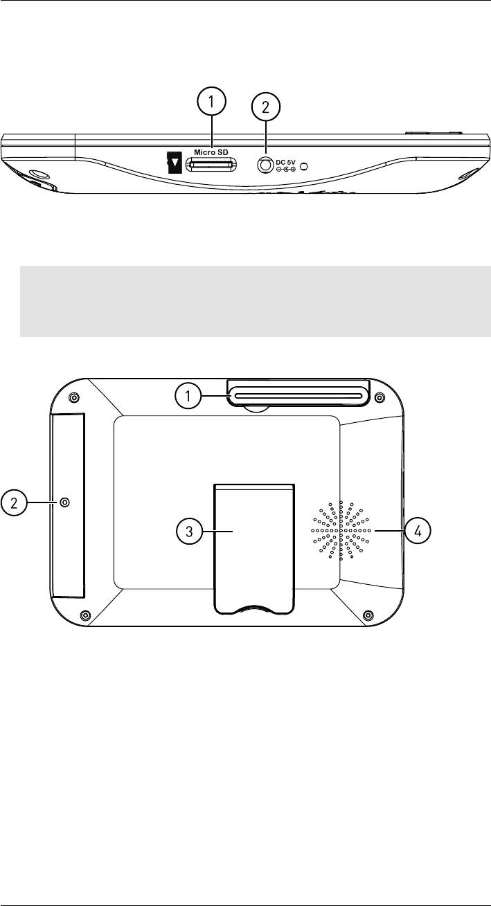
1. Power Port: Connect the included 5V DC adapter to the power port and an electrical
outlet or surge protector to provide power to the receiver.
2. microSD Card Slot: The included 4 GB microSD card comes pre-inserted.
Note
• The receiver supports microSD cards up to 32 GB.
• Lorex recommends microSD or microSDHC cards for use with this receiver. The following brands
of microSD cards are confirmed by Lorex: Adata, Kingston, Patriot, Sandisk, and Toshiba.
7.3 Rear Panel
2
3
1
4
1. Wireless Antenna: Position the antenna as needed for best reception.
2. Battery Compartment: Insert the included rechargeable battery. See for full installa-
tion instructions.
3. Support Stand: Pull out the support stand to for placement on a flat surface.
4. Speaker
#LX400030; r.16602/16610; en-US 14
Using the System
8
By default, the camera(s) included with your system are automatically paired to the re-
ceiver. The camera(s) and receiver will communicate with each other once they are pow-
ered on.
Note
It is recommended to power on the camera(s) before powering on the receiver.
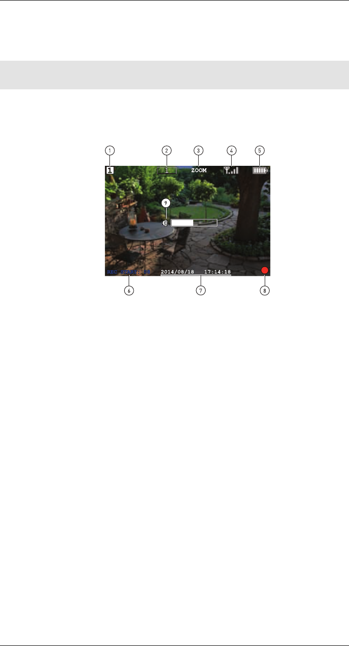
8.1 Understanding the On-screen Display
With camera 1 properly connected and powered on, the system displays a full-screen live
view of the camera.
2014/0 8/18 17:14:18
REC START: 08
1
2 3 45
6
8
7
1
ZOOM
9
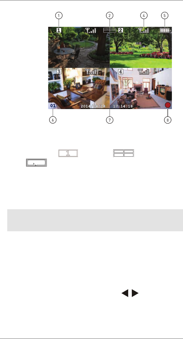
With more than one camera properly connected and powered on, the system displays up
to 4 channels in split screen with the live view of each camera.
#LX400030; r.16602/16610; en-US 15
Using the System
8
2014/0 8/18 17:14:18
1
245
6
8
0
1
7
1. Channel indicator: Displays the camera you are presently viewing. If viewing multiple
cameras at once, the camera indicator will appear above each video display.
2. Viewing mode indicator: Indicates the viewing mode by showing a different icon for
Single Channel Viewing ( ), Quad Viewing ( ), and Auto Sequence
Viewing ( ) modes.
3. Zoom indicator: Indicates that the current live view is zoomed in to twice the original
size.
4. Signal indicator: The signal indicator shows the strength of the signal being received
from the camera. The number of bars in the Signal Indicator shows the strength of the
signal. One, or no bars indicates the signal is poor, and 4 bars indicate a very strong
signal.
Note
• If the signal is low (for example, 1 or 2 bars) adjust the antennas, or reposition the camera(s) or
receiver for best performance.
5. Battery indicator: Shows remaining battery life. Icon turns red when battery is crit-
ically low to indicate that the receiver should be plugged into a local power outlet right
away.
6. Recording countdown: Counts down until system recording starts.
7. Time & date stamp: The current date and time on the system.
8. Recording indicator: A red circle appears when recording is in progress. If viewing
and recording video from multiple cameras at once, the recording indicator will appear
above each video display where recording is enabled.
9. Volume indicator: Shows the current volume of the receiver. The volume indicator ap-
pears on screen when you change the volume using the / keys.
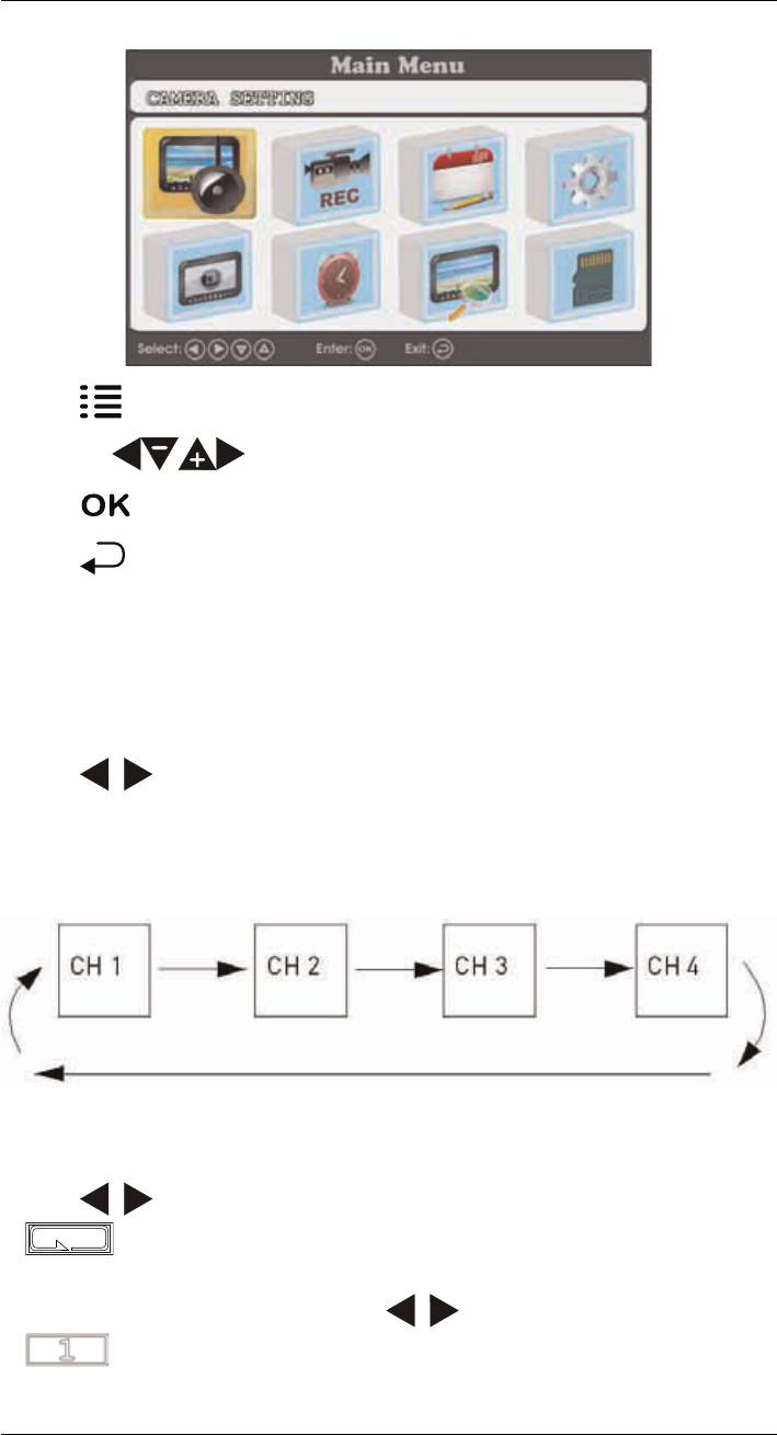
8.2 Navigating Menu Screen
Use the system menus to configure settings.
#LX400030; r.16602/16610; en-US 16
Using the System
8
• Press to open the Main Menu.
• Press the keys to move the cursor left, right, up, and down.
• Press
OK
to open sub-menus and confirm menu selections.
• Press to save changes and exit menus.
8.3 Viewing Modes
There are 3 different viewing modes available on the system: Single Channel Viewing
mode, Auto Sequence Viewing mode (view individual channels automatically in se-
quence), and Quad Viewing mode (view all 4 channels at once in split-screen).
To change viewing modes:
• Press / to select between channels 1–4 in single channel view, as well as to en-
able Quad Viewing and Auto Sequence Viewing modes.
8.3.1 Auto Sequence Viewing Mode
Auto Sequence Viewing mode cycles through connected channels in full-screen.
Auto Sequence Example
To enable Auto Sequence Viewing:
• Press / until a single channel is shown on screen with the Auto Sequence icon (
) at the top of the display. The receiver automatically switches through con-
nected channels.
• To return to single channel viewing, press / until the Single Channel icon (
) appears at the top of the display.
#LX400030; r.16602/16610; en-US 17
Using the System
8
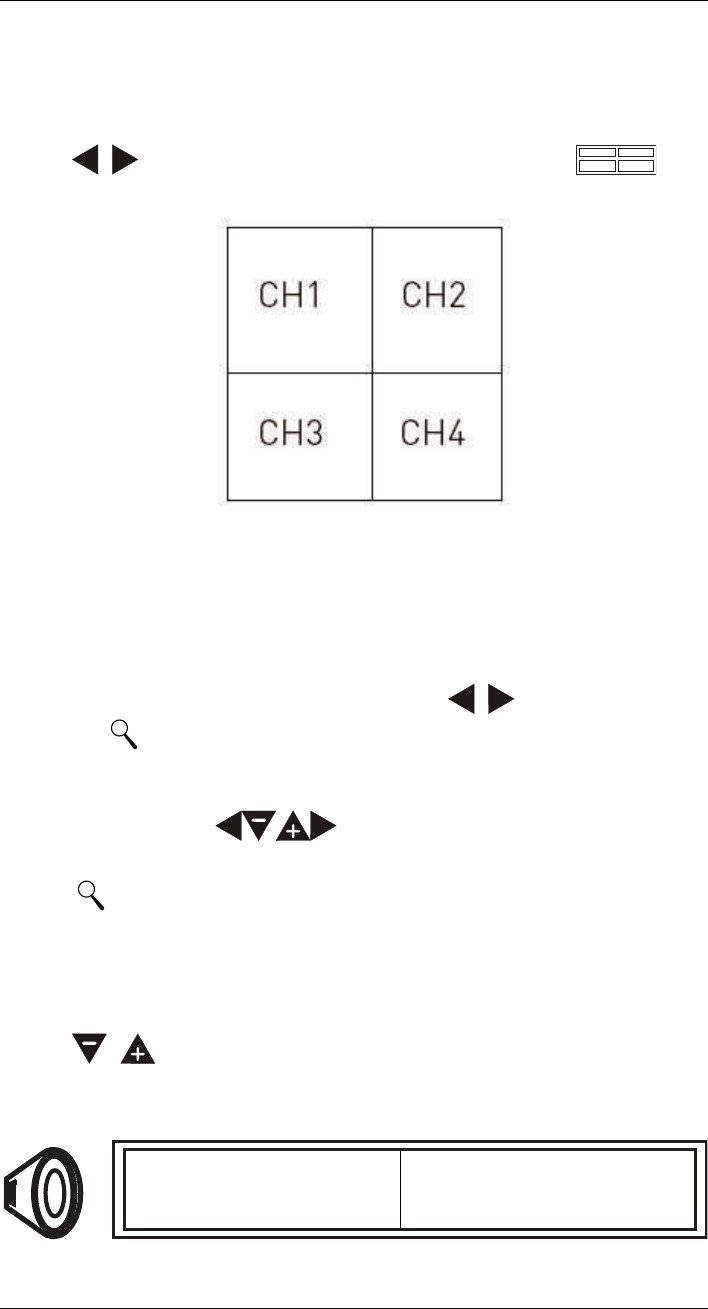
8.3.2 Quad Mode
Use Quad Viewing mode to view up to four cameras simultaneously.
To enable Quad mode:
• Press / until a split-screen display appears with the Quad icon ( ) at
the top of the display. The receiver displays all 4 channels simultaneously.
Quad Example
8.4 Digital Zoom
The digital zoom feature allows you to zoom in 2x on a single camera during live viewing.
This is useful if you need a closer look at something happening far away from the camera.
To use digital zoom:
1. Select the desired camera in full-screen mode (press / to select the channel)
and press on the front panel of the receiver to zoom in.
2. When digital zoom is activated, the live view zooms in to 2x normal magnification. The
word ZOOM appears in the top of the screen, and 4 directional arrows appear over the
camera image. Use the keys to pan in the desired direction and look at
different parts of the image.
3. Press again to exit digital zoom.
8.5 Changing Audio Volume
The receiver can play and record audio from the camera you are currently viewing.
To change the volume:
• Press / to change the audio volume.
The volume meter appears on screen to indicate the volume of audio coming from the cur-
rently selected camera:
#LX400030; r.16602/16610; en-US 18

Setting the Time
9
It is highly recommended to set the date and time on the system prior to recording, as they
will be used to stamp recordings. You must set the correct date and time in order to use
schedule recording.
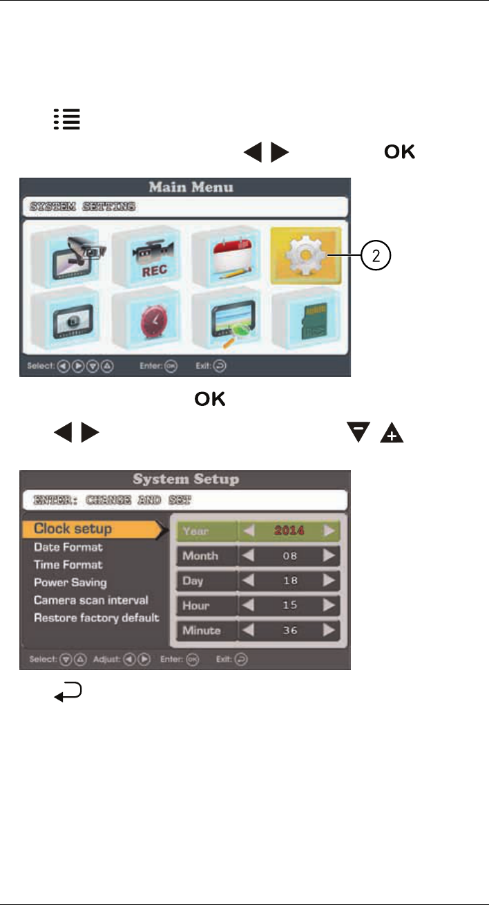
To set the time:
1. Press to open the main menu.
2. Select the system settings icon using the / keys, then press
OK
.
2
3. Select Clock setup, then press
OK
.
4. Press / to configure the current date and time. Press / to move be-
tween items.
5. Press to save your settings and close any remaining menu windows.
The date and time appears at the bottom of the screen in live viewing mode and on re-
corded video.
#LX400030; r.16602/16610; en-US 20
Recording
10
The following recording modes are available on the system: manual recording,scheduled
continuous recording, and scheduled motion recording. The system records video to the
included microSD card.
Recording Prerequisites:
• A microSD card must be inserted into the receiver in order to record video. You should
always format the microSD card prior to initial recording. For details, see 10.1 Format
Memory, page 22.
Maximum Recording Times:
The system supports microSD cards up to 32 GB. Use the table below to help you esti-
mate the recording times on various sizes of microSD cards. Times shown are in hours
and minutes.
microSD Card Capacity Single Channel Recording @ VGA Resolution
1 GB 6.5 hours
2 GB 13 hours
4 GB 26 hours
8 GB 52 hours
16 GB 104 hours
32 GB 208 hours
Note
The system supports microSD or microSDHC cards up to 32 GB. The following brands of microSD cards
are confirmed by Lorex: Adata, Kingston, Patriot, Sandisk, and Toshiba.
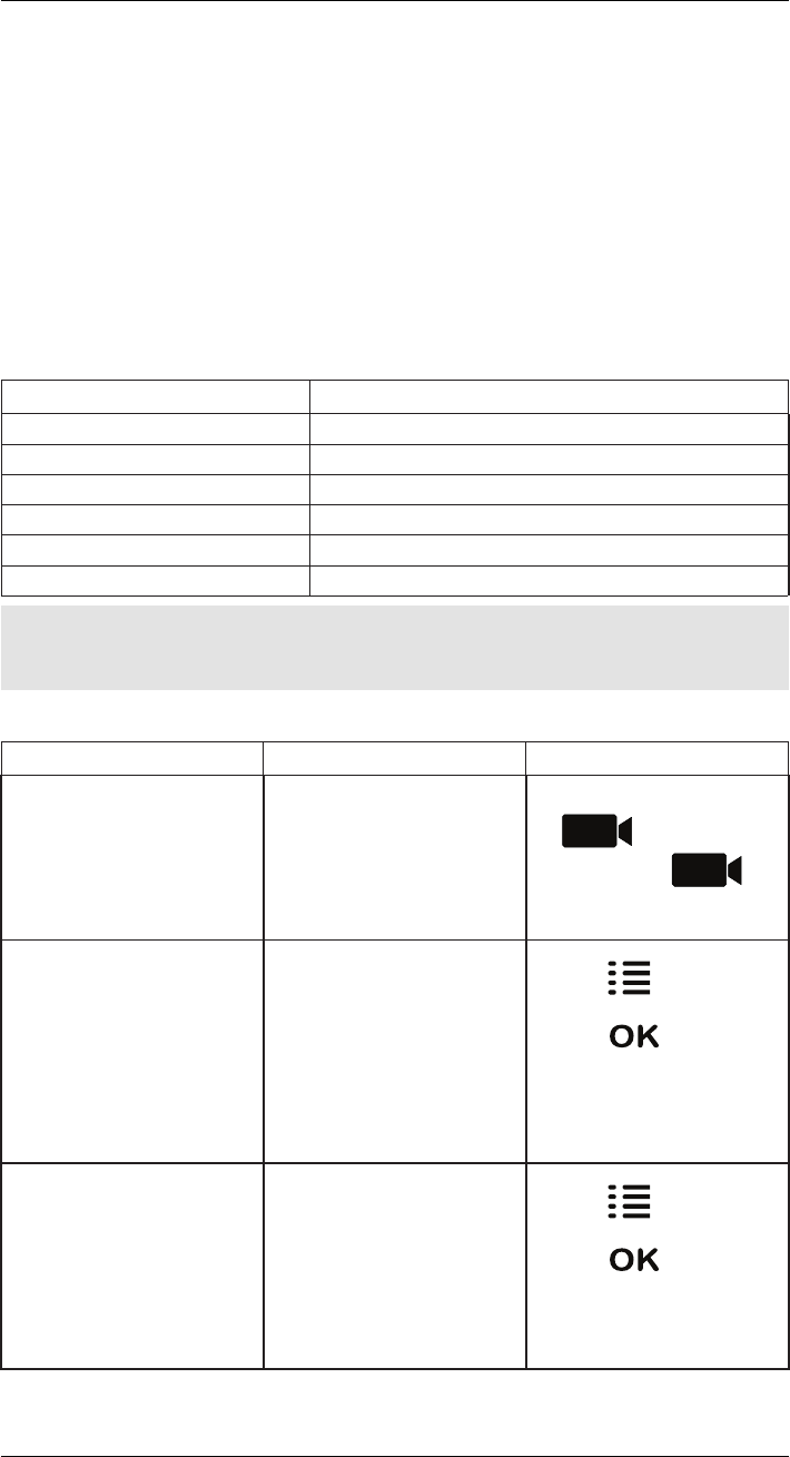
Recording Mode Summary:
Mode Description How to Operate
Manual Recording • Continuous recording from a
single channel in full screen
or all 4 channels in a single
video file.
• During live viewing, press
to begin manual re-
cording. Press
again to stop manual
recording.
Scheduled Continuous
Recording • Records continuously from
all 4 channels in a single vid-
eo file. Recording starts and
stops automatically based on
a daily schedule.
• Press and select the
recording schedule icon.
Press
OK
to confirm. Set
a time range for the system
to record continuous video
during each day. For full set-
up instructions, see
CROSSREF.
Scheduled Motion Recording • Records motion-events only
from all 4 channels in a single
video file. Recording starts
and stops automatically
based on a daily schedule.
• Press and select the
recording schedule icon.
Press
OK
to confirm. Set
a time range for the system
to record motion-events dur-
ing each day. For full setup
instructions, see CROSSREF.
#LX400030; r.16602/16610; en-US 21
Recording
10
10.1 Format Memory
It is highly recommended to format the microSD card prior to initial recording.
To format the microSD card:
CAUTION
Formatting erases all data on the microSD card. This step cannot be undone.
1. Insert the microSD card into the card slot on the receiver until you hear a "click."
Please insert the card according to the diagram on the side panel of the receiver.
2. Press , then select the Record Setting icon. Press
OK
to confirm.
3. Select Format card and press
OK
to confirm.
4. Select Confirm and press
OK
to confirm.
Note
Please allow a few moments for formatting to finish. Formatting time will vary depending on the size
of the card.
5. A message appears to confirm formatting. Press repeatedly until all menus are
closed.
10.2 Scheduled Recording
Use scheduled recording to have the system automatically record continuously or just mo-
tion-events during a set period of time. The system records all 4 channels in Quad mode.
Note
Auto Sequence Viewing mode and Quad mode are available during schedule recording without affecting
the recording files.
Prerequisite:
Please ensure you have set the proper date and time on the receiver prior to setting a re-
cording schedule. See 9 Setting the Time, page 20.
When should I use schedule recording?
• Use scheduled continuous recording if the camera is pointed at an area with high traffic,
such as an entrance way or a road.
• Use scheduled motion recording if the camera is pointed at an area with low traffic,
such as a back door or a storage room.
CAUTION
Do not remove the microSD card while the system is recording. Disable all recording on the system be-
fore ejecting the microSD card.
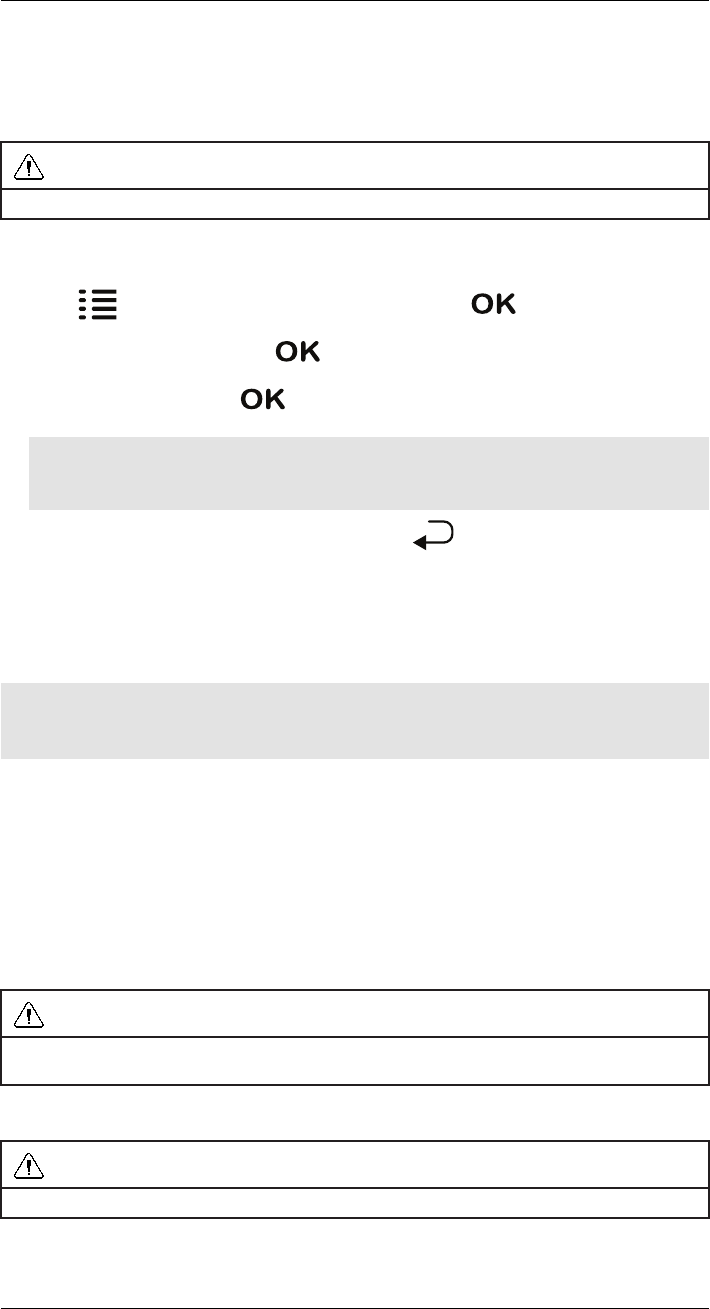
10.2.1 Creating a Recording Schedule
CAUTION
Scheduled recording overrides manual recording.
#LX400030; r.16602/16610; en-US 22
Recording
10
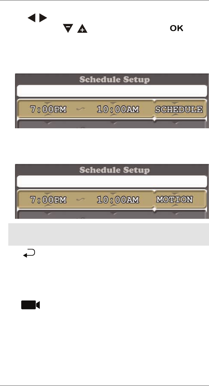
3. Use the / keys to move the selection between the start time, end time, and
schedule type. Use the / keys to configure each item. Press
OK
to save
the schedule.
•For scheduled continuous recording: See the following example. The system
begins recording continuously at 7:00PM and stops recording at 10:00AM each day.
The word SCHEDULE at the end indicates that the system will record continuously
between these times.
•For scheduled motion recording: See the following example. The system begins
recording motion-events only at 7:00PM and stops recording at 10:00AM each day.
The word MOTION at the end indicates that the system will record continuously be-
tween these times.
Note
The appearance of the start and end time will vary depending on the time format. The system sup-
ports both 12–hour and 24–hour time.
4. Press repeatedly until all menus are closed.
10.2.2 Stopping Scheduled Recording
When the stop time arrives, the system stops recording automatically. If necessary, you
can temporarily stop schedule recording manually in order to access the main menu.
To stop schedule recording:
• Press to temporarily stop scheduled recording. If you remain in live view, the
system starts the recording schedule again after 10 seconds. You can access the main
menu during this time to stop the countdown and configure settings. The recording
schedule starts 10 seconds after you re-enter live view.
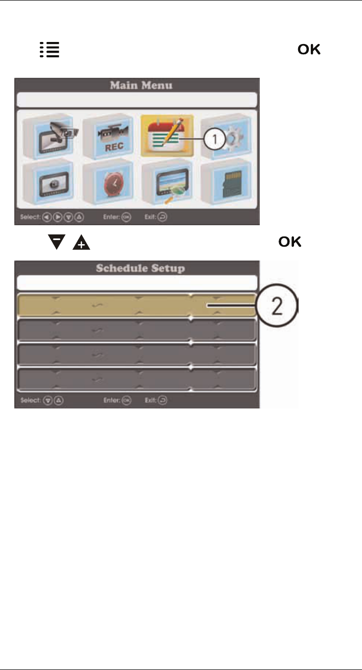
10.2.3 Modifying or Disabling a Recording Schedule
You can modify or disable any recording schedule after it has been created.
To modify a recording schedule:
#LX400030; r.16602/16610; en-US 24
Recording
10
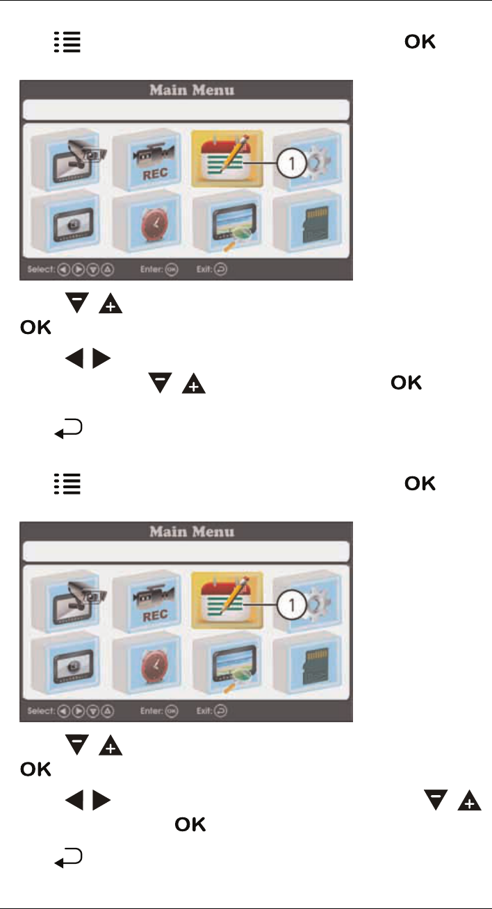
1. Press , then select the Recording Schedule Setting icon. Press
OK
to
confirm.
2. Use the / keys to select the schedule you would like to modify and press
OK
.
3. Use the / keys to move the selection between the start time, end time, and
schedule type. Use the / keys to modify each value. Press
OK
to save the
modified schedule.
4. Press repeatedly until all menus are closed.
To disable a recording schedule:
1. Press , then select the Recording Schedule Setting icon. Press
OK
to
confirm.
2. Use the / keys to select the schedule you would like to delete and press
OK
.
3. Use the / keys to move the selection to the schedule type. Use the /
keys to select NONE. Press
OK
to save your settings.
4. Press repeatedly until all menus are closed.
#LX400030; r.16602/16610; en-US 25
Recording
10
10.3 Manual Recording
Manual recording allows you to manually start and stop recording. You can record video
from one channel in full-screen, or all 4 channels in Quad or Auto Sequence Viewing
mode.
When should I use manual recording?
• Recording of unexpected events or emergencies.
To enable manual recording:
1. Use the / keys to select the viewing mode you want to record.
2. Press to begin recording the current view.
A recording indicator ( ) appears on screen to indicate the system is recording.
3. Press again to stop recording.
CAUTION
Do not remove the microSD card while the system is recording. Disable all recording on the system be-
fore ejecting the microSD card.
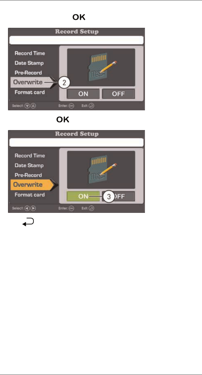
10.4 Enabling / Disabling File Overwrite
Enabling file overwrite will delete the oldest recorded data on the microSD card once it is
full to make room for new recordings.
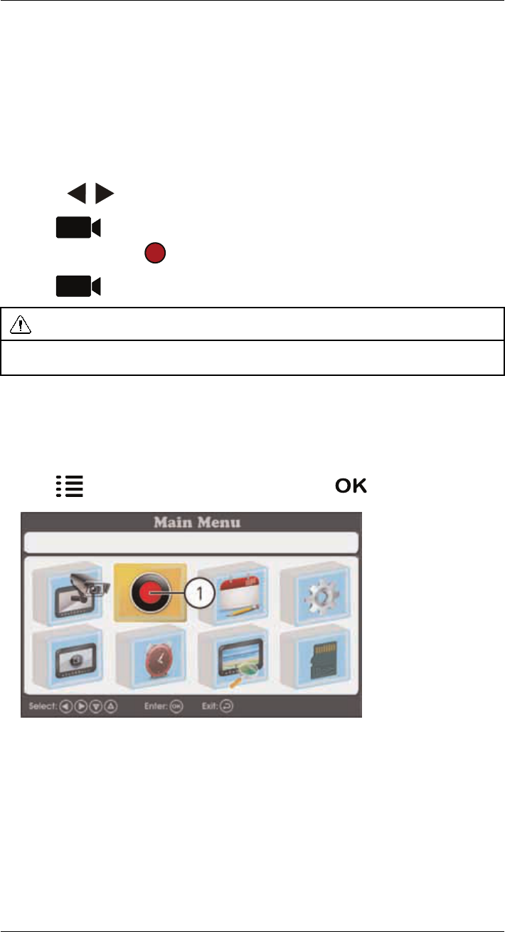
To enable file overwrite:
1. Press , then select the Record Setting icon. Press
OK
to confirm.
#LX400030; r.16602/16610; en-US 26
Playback
11
Playback mode allows you to playback recorded video files and view snapshots from the
microSD card. You can view videos and snapshots directly on the system or by connecting
the microSD card to your computer.
11.1 Video Playback
To playback recorded video on the system:
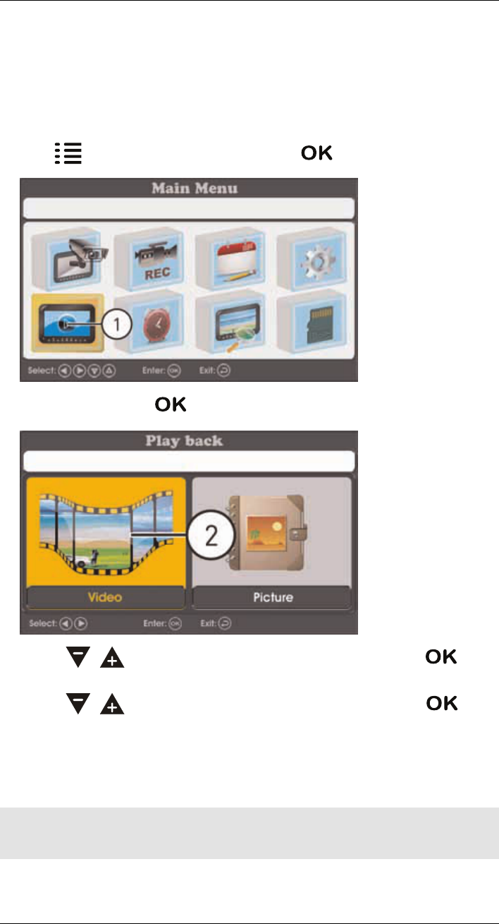
1. Press , then select the Event List icon. Press
OK
to confirm.
2. Select Video and press
OK
.
3. Use the / keys to choose a date to search for video from. Press
OK
to
confirm.
4. Use the / keys to choose an hour to search for video fromPress
OK
to
confirm.
11.2 Viewing Video Directly from the microSD Card
You can view the saved video files on your computer (PC or Mac) by using a microSD card
reader (not included). Saved video files are in ASF format.
Note
Some PCs and Macs may have a microSD card reader built-in. Please refer to your computer's instruc-
tion manual for more details.
#LX400030; r.16602/16610; en-US 28

Playback
11
11.2.1 PC
Note
You can view ASF files natively in Windows Media Player™, as well as other media players such as VLC.
VLC is an open-source software application available at www.videolan.org
To playback recorded video on a PC:
1. Remove the microSD card from the receiver by gently pushing on the microSD card
and then releasing. The card will eject.
2. Insert the microSD card into a microSD card reader (not included) connected to your
PC. Your PC should load the microSD card as a new Removable Drive and an Autorun
window opens.
3. Click Open folder to view files or open the folder in Computer. Open the folder MFG.
You will then see a folder for each page of recorded video in Playback mode. Folders
are named by page number (e.g. recordings found on the second page are in the fold-
er 00000002).
4. Double-click any of the ASF files. The video will begin playing in your default ASF me-
dia player.
11.2.2 Mac
Note
Downloading and installing the Flip4Mac WMV Components will allow you to play ASF files in QuickTime.
VLC Player is recommended for viewing ASF files on a Mac. VLC is an open-source software application
available at www.videolan.org
To playback recorded video on a Mac:
1. Remove the microSD card from the receiver by gently pushing on the microSD card.
The card will eject.
2. Insert the microSD card into a microSD card reader (not included) connected to your
Mac. Your Mac should load the microSD card as a new disk on your desktop.
3. Double-click the disk on your desktop or open it through Finder. Open the folder MFG.
You should see a folder for each page of recorded video in Playback mode. Folders
are named by page number (e.g. recordings found on the second page are in the fold-
er 00000002).
4. Double-click any of the ASF files. The video will begin playing in your default ASF me-
dia player.
#LX400030; r.16602/16610; en-US 29
Pairing Additional Cameras
12
Note
If you have purchased additional cameras, it is highly recommended to pair the cameras to the receiver
before permanent installation.
"Pairing" is an electronic handshake between wireless devices. Wireless devices and
components need to be paired in order to communicate with each other.
The camera(s) provided with the system have already been paired to the receiver. By de-
fault, the camera(s) included are automatically paired to channels 1 & 2 on the receiver.
See the channel label on the camera to check which channel it has been set to.
If you have purchased additional accessory cameras, you will need to pair them to the re-
ceiver. When pairing cameras, you can select the channel you would like the cameras to
be assigned to. You can also use the steps below to reassign your existing cameras to dif-
ferent channels.
Note
Accessory cameras (model# LW1741AC1) are available from www.lorextechnology.com.
To pair an additional camera:
1. Connect the new camera to a power outlet. Place the camera and the receiver within
1ft of each other.
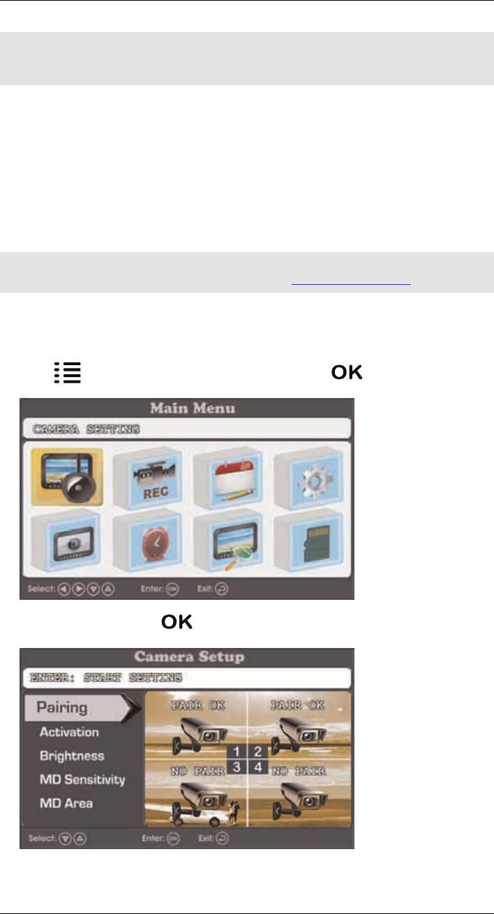
2. Press , then select the Camera Setting icon. Press
OK
to confirm.
3. Select Pairing and press
OK
.
#LX400030; r.16602/16610; en-US 30
Pairing Additional Cameras
12
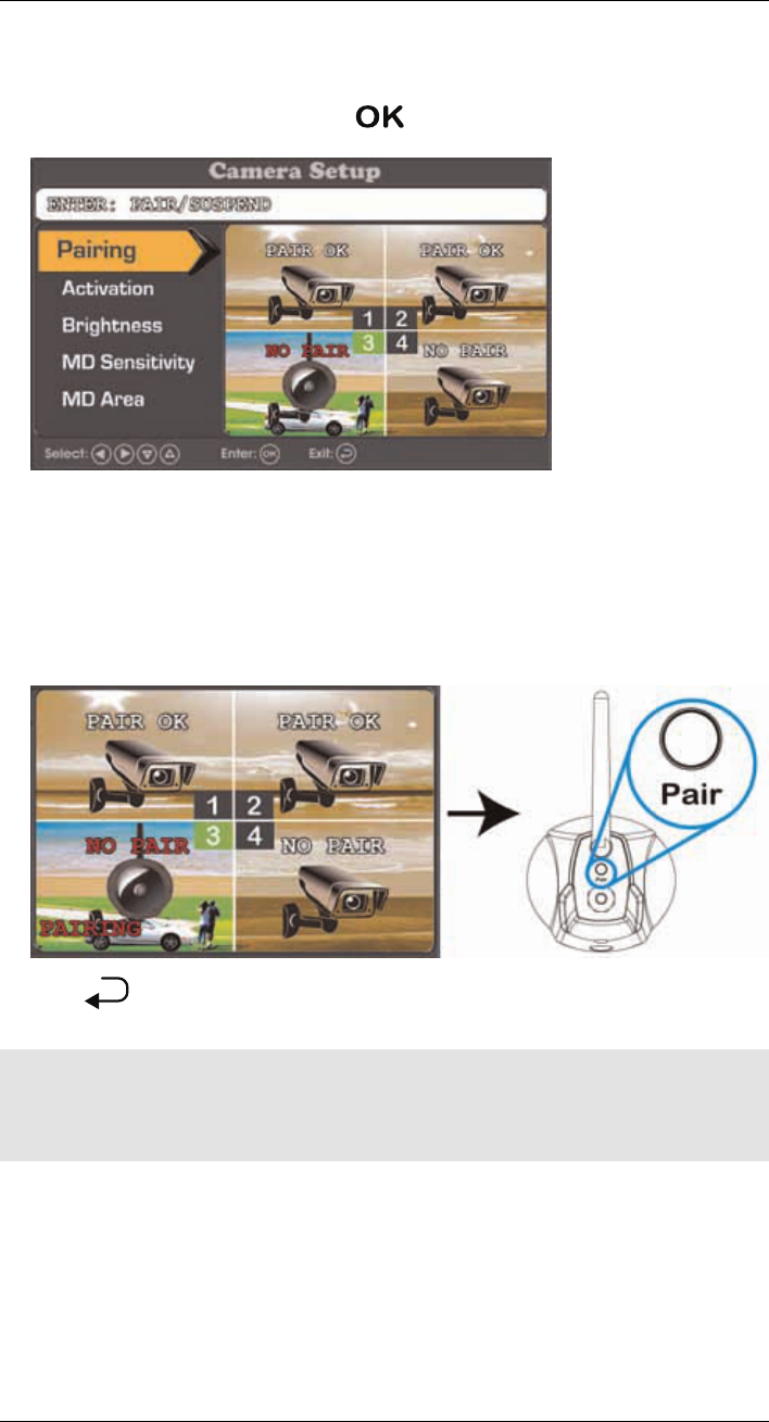
4. Use the arrow keys on the receiver to select the channel you want to pair the camera
to. Channels that are paired to an existing camera show the statement PAIR OK, while
open channels show NO PAIR. Press
OK
on the desired channel to begin pairing.
• If you pair a new camera to a channel that is already being used by an existing cam-
era, the new camera will be connected to that channel. The old camera will auto-
matically be disconnected.
5. Following the on-screen prompt (the selected channel shows the statement PAIRING),
press the Pair button behind the camera. You have 10 seconds to press the Pair but-
ton on the camera. If pairing was successful, the pairing channel shows the statement
PAIR OK.
6. Press until you have exited all menus. You can now view live video from the cam-
era by selecting the channel using the arrow keys on the receiver.
Note
• If pairing was unsuccessful, the pairing channel shows the statement TIME OUT. Repeat steps 2~5 to
try the pairing process again.
• If the speaker begins squealing, move the camera and receiver away from each other.
#LX400030; r.16602/16610; en-US 31

2,400 ~ 2,483.5MHz
Technical Specifications
13
13.1 General Specifications
Description Specification
Transmission Frequency
Transmission Power
Data Rate 3 Mbps
Unobstructed Wireless Range Up to 450ft (m) outdoors
Up to 150ft (m) indoors (disclaimer!)
Spread Spectrum FHSS
Modulation GFSK
Operating Humidity < 80%
13.2 Camera Specifications
Description Specification
Image Sensor 1/5" CMOS Image Sensor
Supported Resolutions VGA (640x480) up to 25 fps
Minimum Illumination < 20Lux (IR on) / > 60Lux (IR off)
AGC Auto
AES Speed 1/60~1/10,000 Second
IR LEDs 24 pieces; 850nm
Night Vision Range 65ft (20m) / 45ft (14m) (disclaimer!)
Lens / Lens Type 2.8mm F2.8 / Fixed
Field of View (Diagonal) 65°
Power Consumption ???mA
Power Supply 6V DC 800mA ±5%
Indoor / Outdoor Both (IP65) (disclaimer!)
Operating Temperature 14 ~ 122°F / –10 ~ 50°C
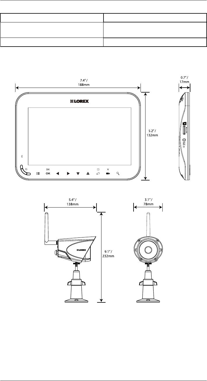
Dimensions (W x D x H) 5.4” x 3.1” x 9.1”
138mm x 78mm x 232mm
Weight ???
13.3 Receiver Specifications
Description Specification
LCD Display 7” Diagonal
LCD Resolution 800x480
Receiving Sensitivity -88dBm
Image Processing MPEG4
Battery 3.7V 3000mAh Li-polymer
Power Consumption ??????mA
Power Supply 5V DC 2A ±5%
Operating Temperature 32 ~ 122°F / 0 ~ 50°C
#LX400030; r.16602/16610; en-US 32
16dBm(Camera) 20dBm(Monitor)
Technical Specifications
13
Description Specification
Dimensions (W x D x H) 7.4” x 5.2” x 0.7”
188mm x 132mm x 17mm
Weight ???
13.4 Dimensions
13.4.1 LCD Receiver
OK
5.2” /
132mm
7.4” /
188mm
Micr o S D
DC 5 V
0.7” /
17mm
13.4.2 Camera with Metal Stand
9.1” /
232mm
5.4” /
138mm
3.1”
/
78mm
#LX400030; r.16602/16610; en-US 33
Frequently Asked Questions
15
Q: Does a wireless camera require power?
A: Yes. Wireless cameras require two power sources: one connected to the camera, and
the other to the receiver. The term "wireless" refers to the lack of a video cable between
the camera and the receiver.
Q: How far can a wireless camera transmit a video signal?
A: In an open field (with line of sight), a typical wireless camera has a range between 250 -
500 feet. 'Line-of-sight' means that there are no obstructions between the camera and re-
ceiver. Obstructions include walls, buildings, trees, and certain electronic devices. Materi-
als containing moisture (for example, leaves) may also act as an obstruction. Cubical
walls, drywall, glass, and windows generally do not degrade wireless signal strength.
In a closed environment—such as the interior of a house—the wireless camera range is
between 100 - 165 feet. The signal range varies depending on the type of building materi-
als or objects the wireless signal must pass through.
The signal range also depends on whether there are competing signals using the same
frequency as the camera. For example, signals from cordless phones or routers may affect
signal strength. Adaptive Frequency Hopping Spread Spectrum (FHSS) technology fea-
tured in the latest Lorex models greatly reduces signal interference.
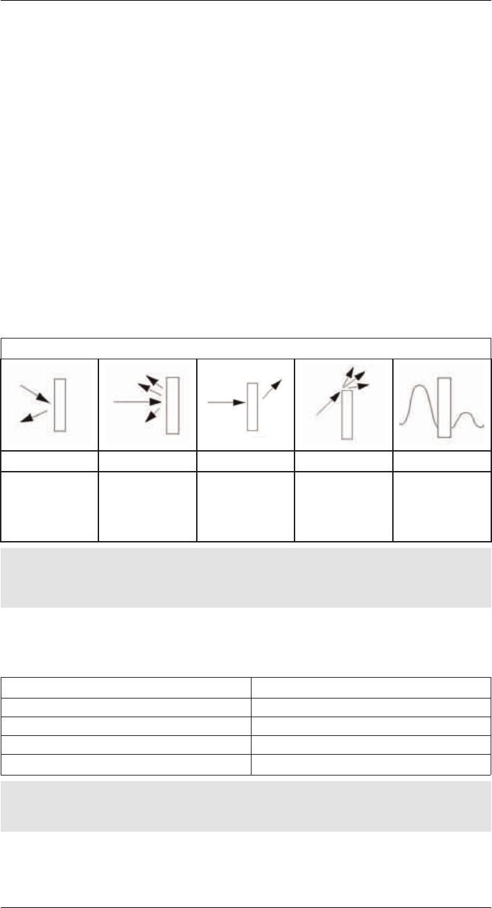
Range Limiting Factors1
Reflection Scattering Refraction Diffraction Attenuation
The signal reflects
back
The signal scat-
ters back into mul-
tiple new signals
The signal bends
as it travels
through an object
(e.g. glass
window)
The signal
changes direction
as it passes
around an object
The signal
strength weakens
as it passes
through an object
Note
1. Source: Xirrus (2010). "Wi-Fi Range Dynamics". Retrieved online at http://xirrus.gcsmarket.com/
pdfs/Xirrus_Wi-Fi_Range.pdf
Signal Reduction Through Materials
Signal strength decreases as it passes through different types of material. The table below
shows how signals become reduced when passing through different materials:
Material Signal Reduction (%)
Plaster & Wood 10 - 30%
Brick 30 - 50%
Concrete Cinder Blocks 50 - 70%
Metal & Metal Cladding 70 - 90%
Note
Signals that must pass through wet or moist materials (e.g. shrubs and trees) may be significantly
reduced.
#LX400030; r.16602/16610; en-US 35

Frequently Asked Questions
15
The stronger the signal strength, the higher the video frame rate. The lower the signal
strength, the lower the video frame rate.
Full signal strength
(high frame rate)
Low signal strength
(low frame rate)
Q: Are digital wireless camera signals secure?
A: Yes. Lorex digital wireless products feature a wireless transmission method called Fre-
quency Hopping Spread Spectrum (FHSS). This type of signal is highly resistant to eaves-
dropping as it generates a channel hopping sequence using an algorithm generated by
the receiver, which only the camera can follow through the "pairing" function.
Pairing is an electronic handshake between digital wireless devices. Digital wireless cam-
eras can only be paired to one receiver. This is to prevent interception by third parties, and
prevents any other device from picking up the signal—this also means that you cannot pair
one camera to multiple receivers.
Q: How many frames per second should I expect from a digital wireless camera?
A: Current Lorex digital wireless cameras offer 10 - 30 FPS (Frames Per Second) perform-
ance. Actual frame rate depends mainly on signal strength (see the chart in section
above).
#LX400030; r.16602/16610; en-US 36

last page
Publ. No.: LX400030
Commit: 16602
Head: 16610
Language: en-US
Modified: 2014-08-22
Formatted: 2014-08-25
Website
www.lorextechnology.com
Copyright
© 2014, Lorex Corporation
All rights reserved worldwide. Names and marks appearing herein are either registered trademarks or trademarks of Lorex Corporation and/or its subsidiaries. All
other trademarks, trade names or company names referenced herein are used for identification only and are the property of their respective owners.
Legal disclaimer
As our product is subject to continuous improvement, Lorex Corporation & subsidiaries reserve the right to modify product design, specifications & prices without
notice and without incurring any obligation.E&OE.

uncontrolled environment .This equipment for camera should be installed and operated with
FCC Caution:
Any Changes or modifications not expressly approved by the party responsible for compliance
could void the user's authority to operate the equipment.
This device complies with part 15 of the FCC Rules. Operation is subject to the following two
conditions: (1) This device may not cause harmful interference, and (2) this device must
accept any interference received, including interference that may cause undesired operation.
FCC Radiation Exposure Statement:
This equipment complies with FCC radiation exposure limits set forth for an
minimum distance 20cm between the radiator& your body.
This transmitter must not be co-located or operating in conjunction with any other antenna or
transmitter.
This device complies with Industry Canada licence-exempt RSS standard(s). Operation is subject
to the following two conditions: (1) this device may not cause interference, and (2) this device
must accept any interference, including interference that may cause undesired operation of the
device.
Le présent appareil est conforme aux CNR d'Industrie Canada applicables aux appareils radio exempts de licence.
L'exploitation est autorisée aux deux conditions suivantes:
(1) l'appareil ne doit pas produire de brouillage, et
(2) l'utilisateur de l'appareil doit accepter tout brouillage radioélectrique subi, même si le brouillage est susceptible
Under Industry Canada regulations, this radio transmitter may only operate using an antenna of a
type and maximum (or lesser) gain approved for the transmitter by Industry Canada. To reduce
potential radio interference to other users, the antenna type and its gain should be so chosen that
the equivalent isotropically radiated power (e.i.r.p.) is not more than that necessary for successful
communication.
Conformément à la réglementation d'Industrie Canada, le présent émetteur radio peut fonctionner
avec une antenne d'un type et d'un gain maximal (ou inférieur) approuvé pour l'émetteur par Industrie Canada.
Dans le but de réduire les risques de brouillage radioélectrique à l'intention des autres utilisateurs,
il faut choisir le type d'antenne et son gain de sorte que la puissance isotrope rayonnée équivalente (p.i.r.e.)
ne dépasse pas l'intensité nécessaire à l'établissement d'une communication satisfaisante.
d'en compromettre le fonctionnement.
IC Warning:
I
for camera