Lotek Wireless BIOTRACKER Telemetry Receiver User Manual BC03 Biotracker Manual Rev B
Lotek Wireless, Inc Telemetry Receiver BC03 Biotracker Manual Rev B
UserManual.wiki
>
Lotek Wireless
>
BIOTRACKER User Manual
user manual
Navigation menu
Upload a User Manual
Namespaces
Wiki Guide
HTML
PDF
Info
Views
User Manual
Discussion / Help
Navigation
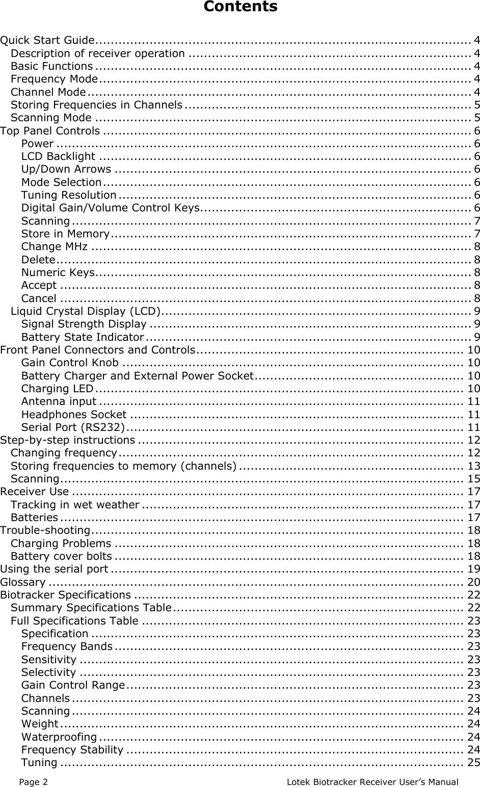
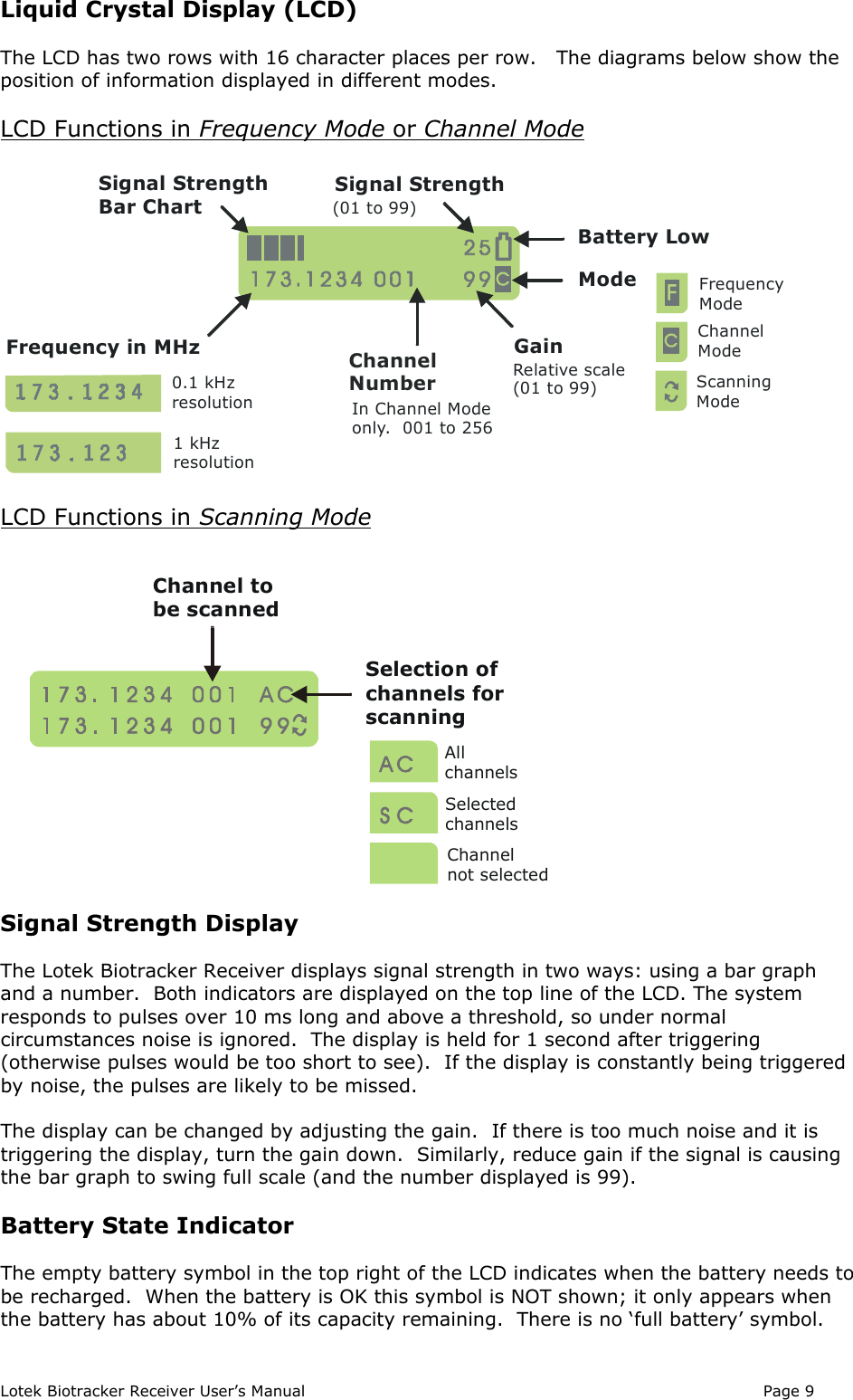
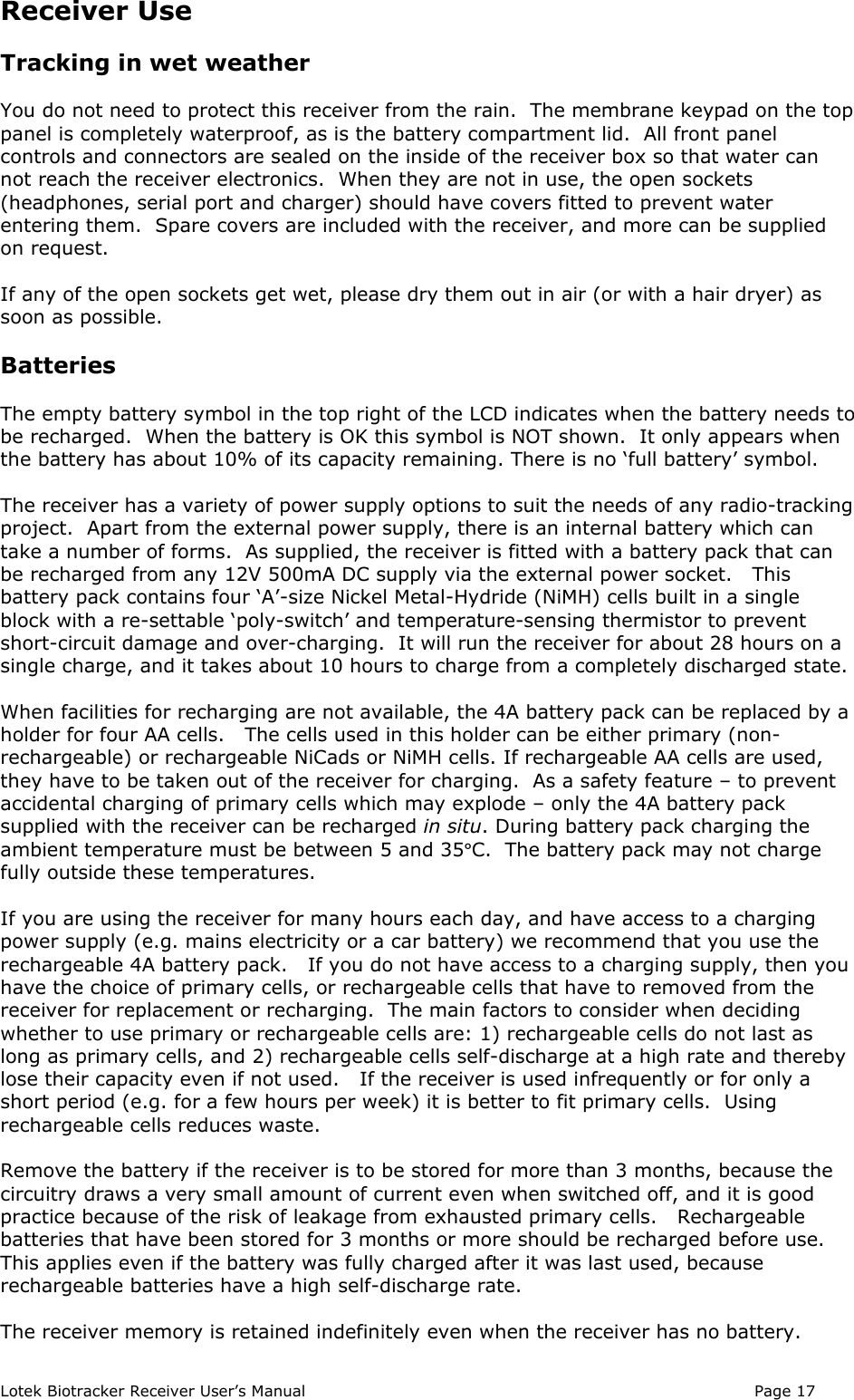
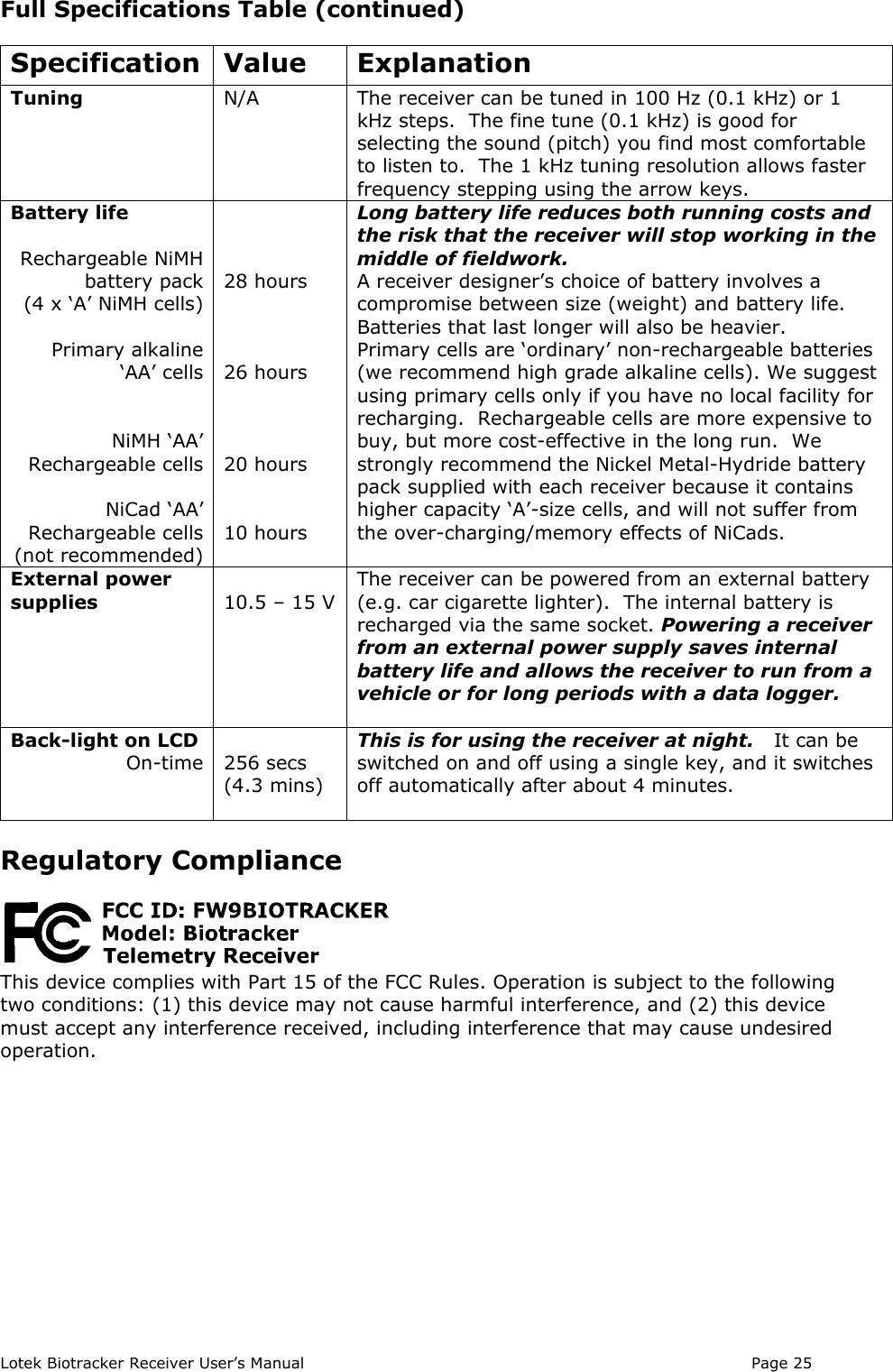
![Page 4 Lotek Biotracker Receiver User’s ManualQuick Start GuideBefore first use, we recommend you put the Biotracker on charge. The battery is fully-charged when the receiver is manufactured, but rechargeable batteries self-dischargeslowly over time and after any period of storage will not be at full capacity.Description of receiver operationThe receiver has three modes: Frequency, Channel and Scan.Frequency Mode: Frequency is set directly via the numeric keypad or arrow keys.Channel Mode: Channels holding stored frequencies are selected via the numerickeypad or arrow keys. There are 256 channels.Scan Mode: The receiver steps in numerical sequence through all channels orselected channels only.Basic Functions• To turn the receiver on and off hold [ON/OFF] down for at least a second.• To toggle between Frequency and Channel Mode (shown by ‘F’ or ‘C’ in bottom rightcorner of display) press [F/C].• [X] cancels the current operation.• [] enters the current number (channel, frequency etc) or completes the currentoperation.• [DEL] deletes the character at current cursor position. To delete the contents of achannel in Channel Mode hold the button down for more than a second.• The key with the light bulb symbol toggles the display back-light on and off. The lightswitches off automatically after about 4 minutes.• To adjust receiver gain, use the keys with loudspeaker symbols. The gain level (00 to99) is displayed next to the mode indicator on the bottom row of the LCD. Gain canalso be adjusted (up to the limit shown in the display) using the gain knob. The knobdoes not change the gain level displayed on the LCD.• Signal strength is displayed on the top line of the LCD as a horizontal bar graph, andthe peak signal value is displayed on the top right. The peak value is held on thedisplay for 1 second or updated if another signal is received sooner.Frequency Mode• In Frequency Mode ‘F’ is displayed in the bottom right corner of the display.• Typing a number enters the kHz frequency units (numbers after the decimal point).Press [] to set the frequency or [X] to cancel and revert back to the previousfrequency.• To change the MHz frequency (numbers before the decimal point) press [MHz].Enter the MHz frequency and press [] to set or [X] to cancel.• The up/down arrows tune the frequency one step at a time, at the current tuningresolution (1 kHz or 0.1 kHz).• The tuning resolution is toggled between 1 kHz and 0.1 kHz by the keymarked [.000 / .0000].Channel Mode• In Channel Mode ‘C’ is displayed in bottom right corner of display.• The up/down arrows step through stored channels in the receiver’s memory.• Channels can also be recalled by entering a channel number. Press [] to setor [X] to cancel.• To delete the contents of a channel, press [DEL] for a second or more.](https://usermanual.wiki/Lotek-Wireless/BIOTRACKER/User-Guide-865317-Page-4.png)
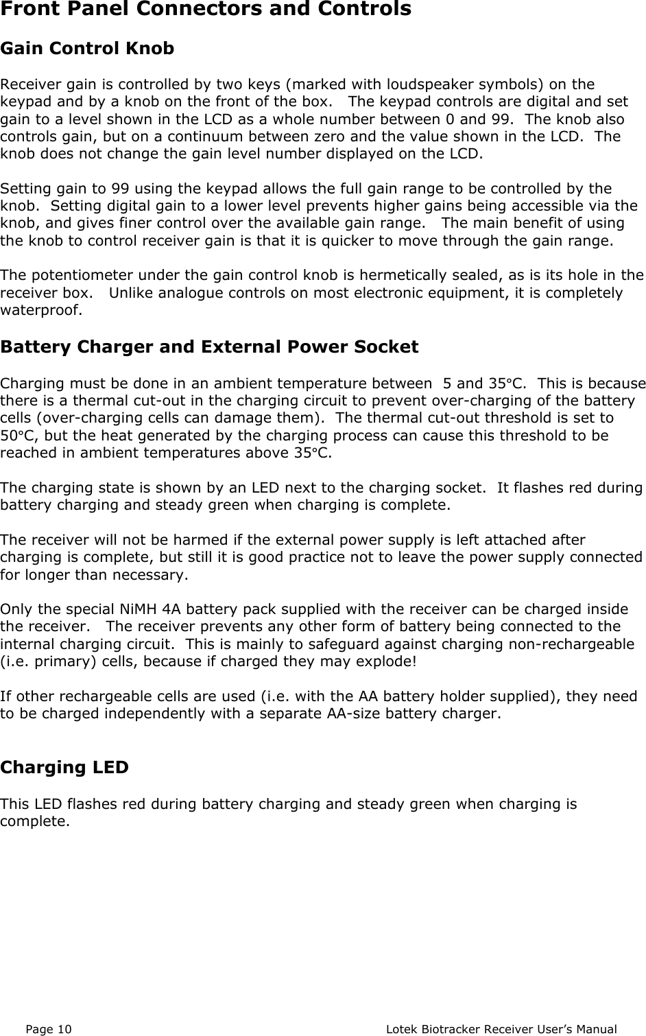
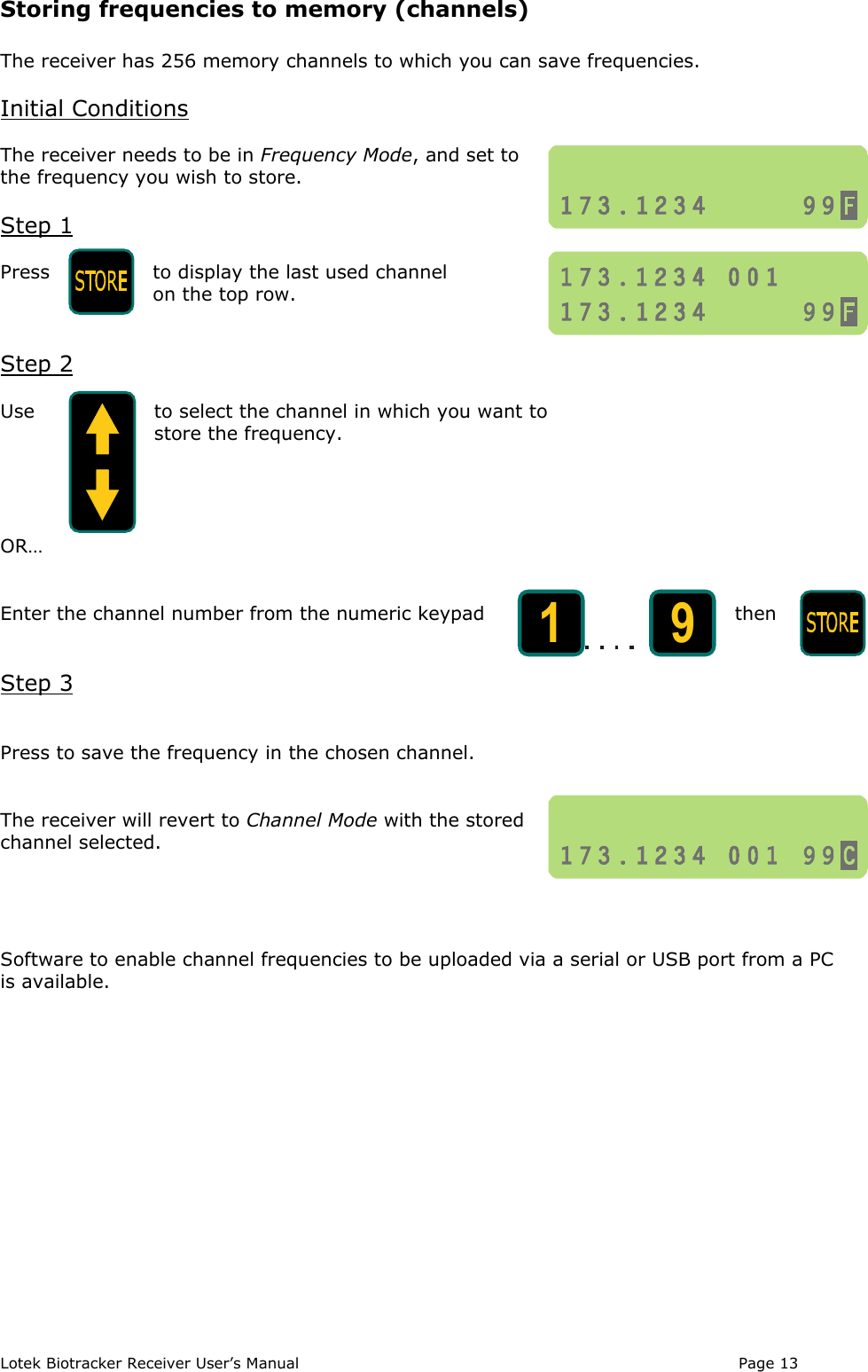
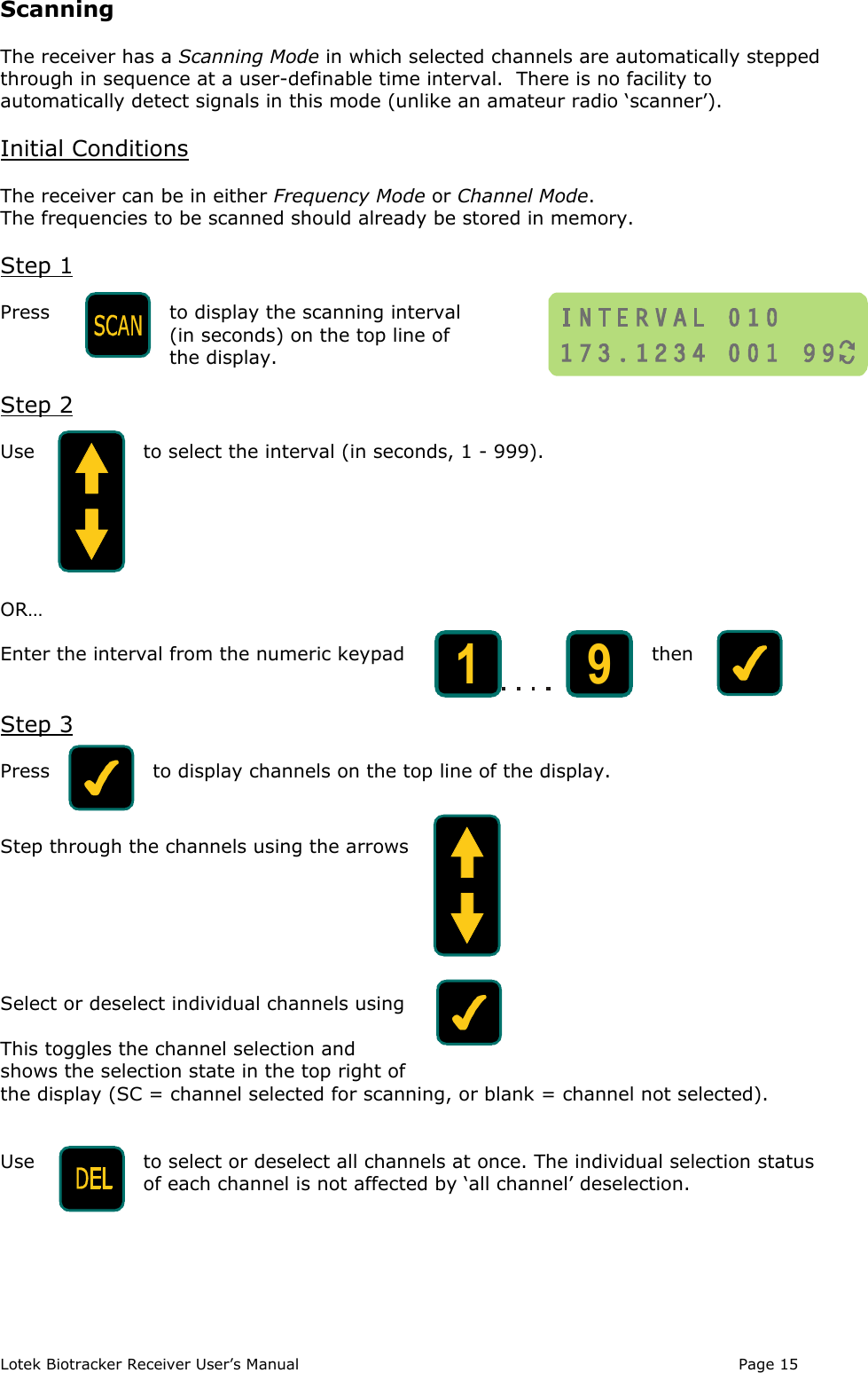
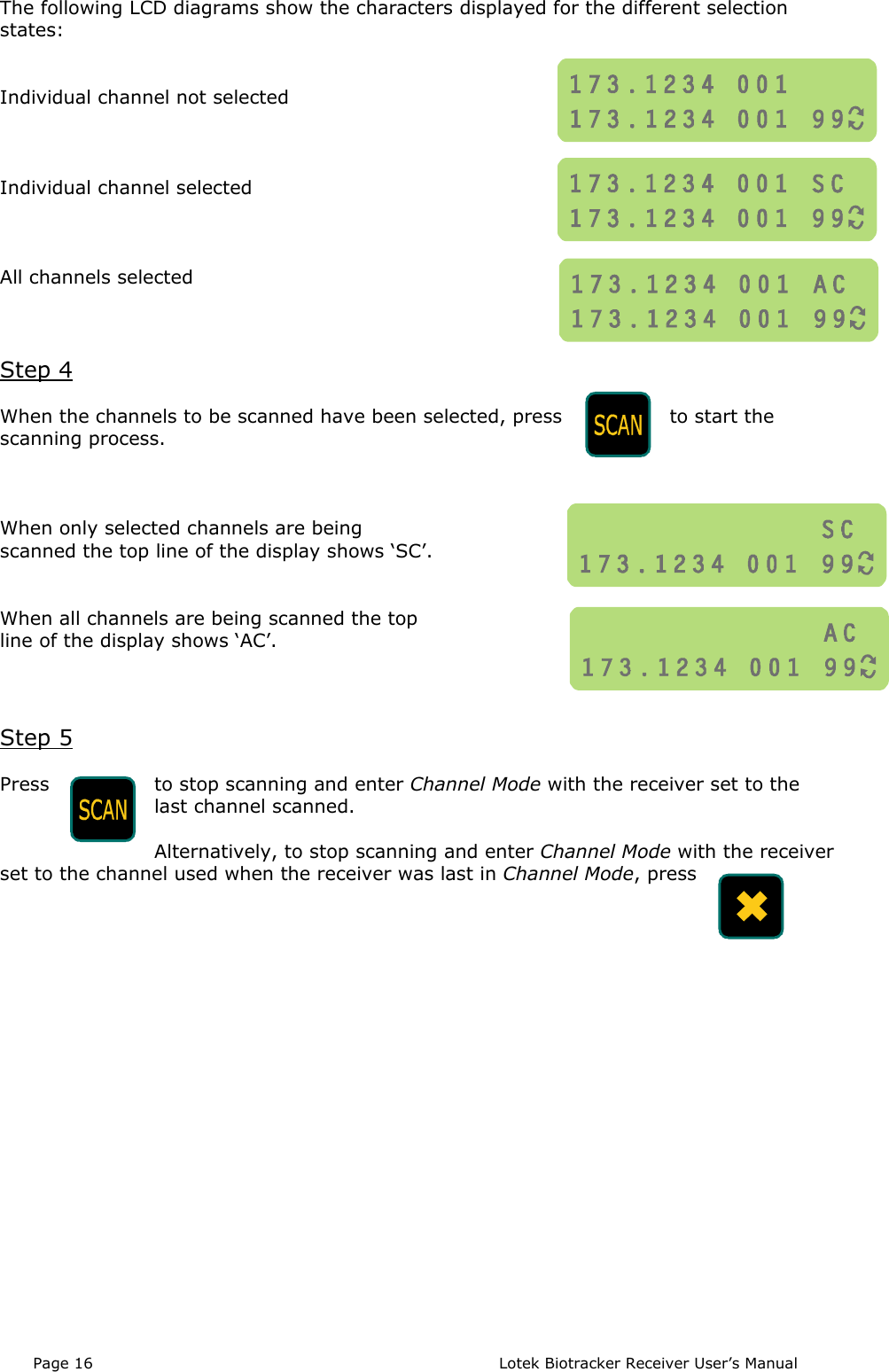
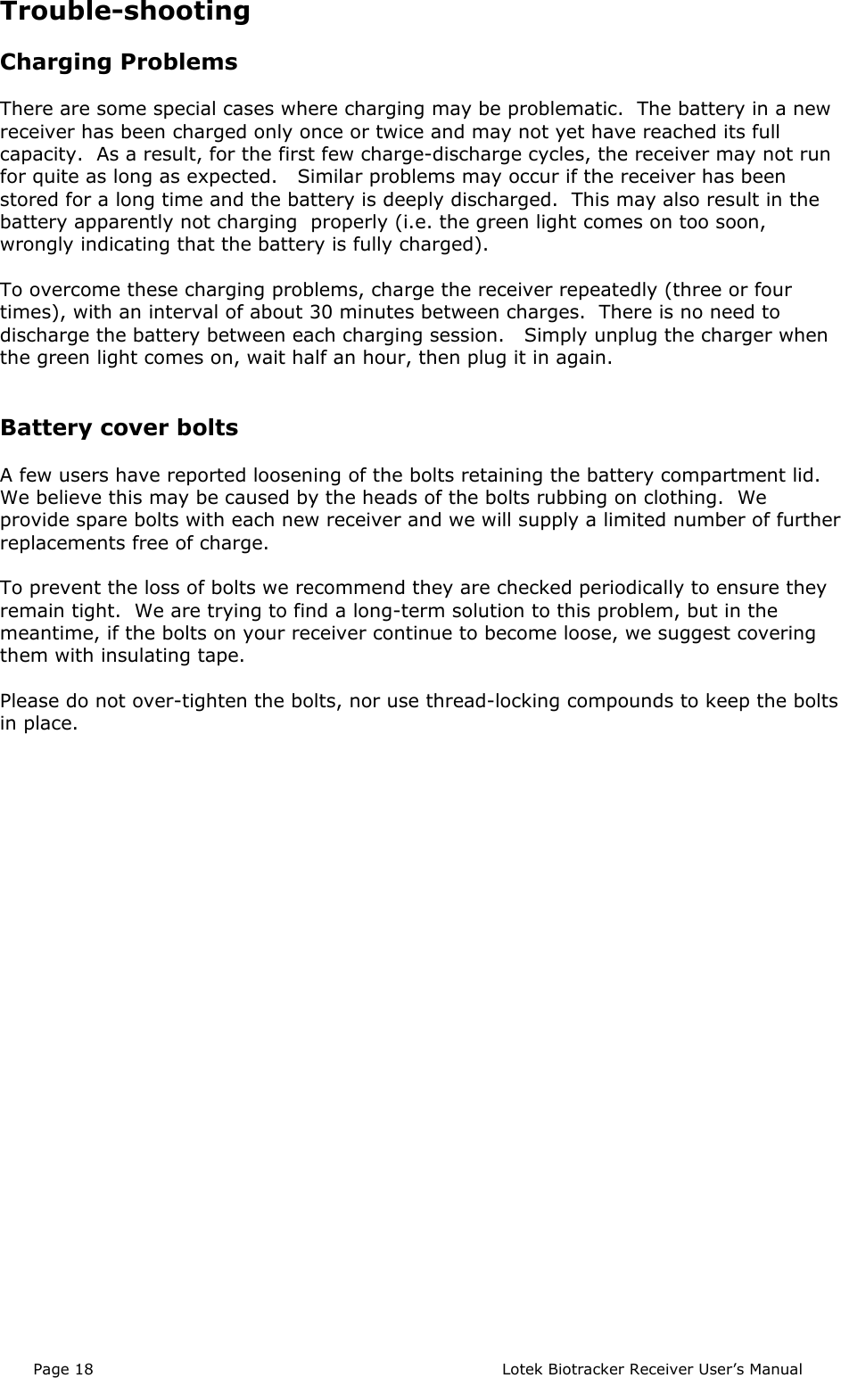
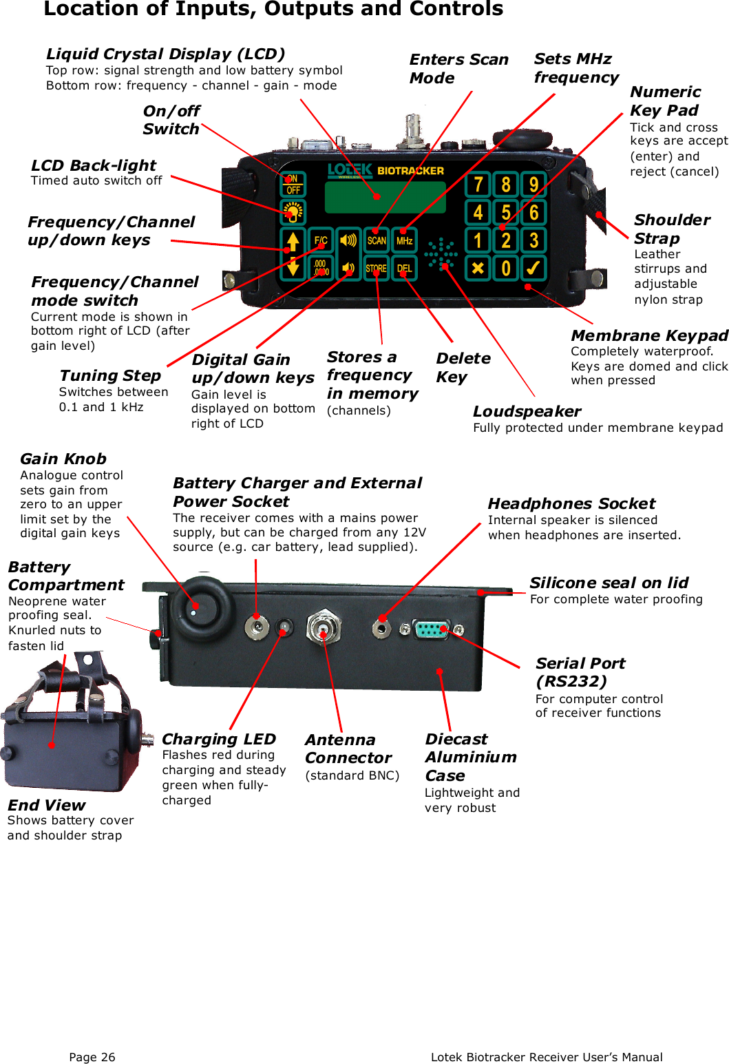
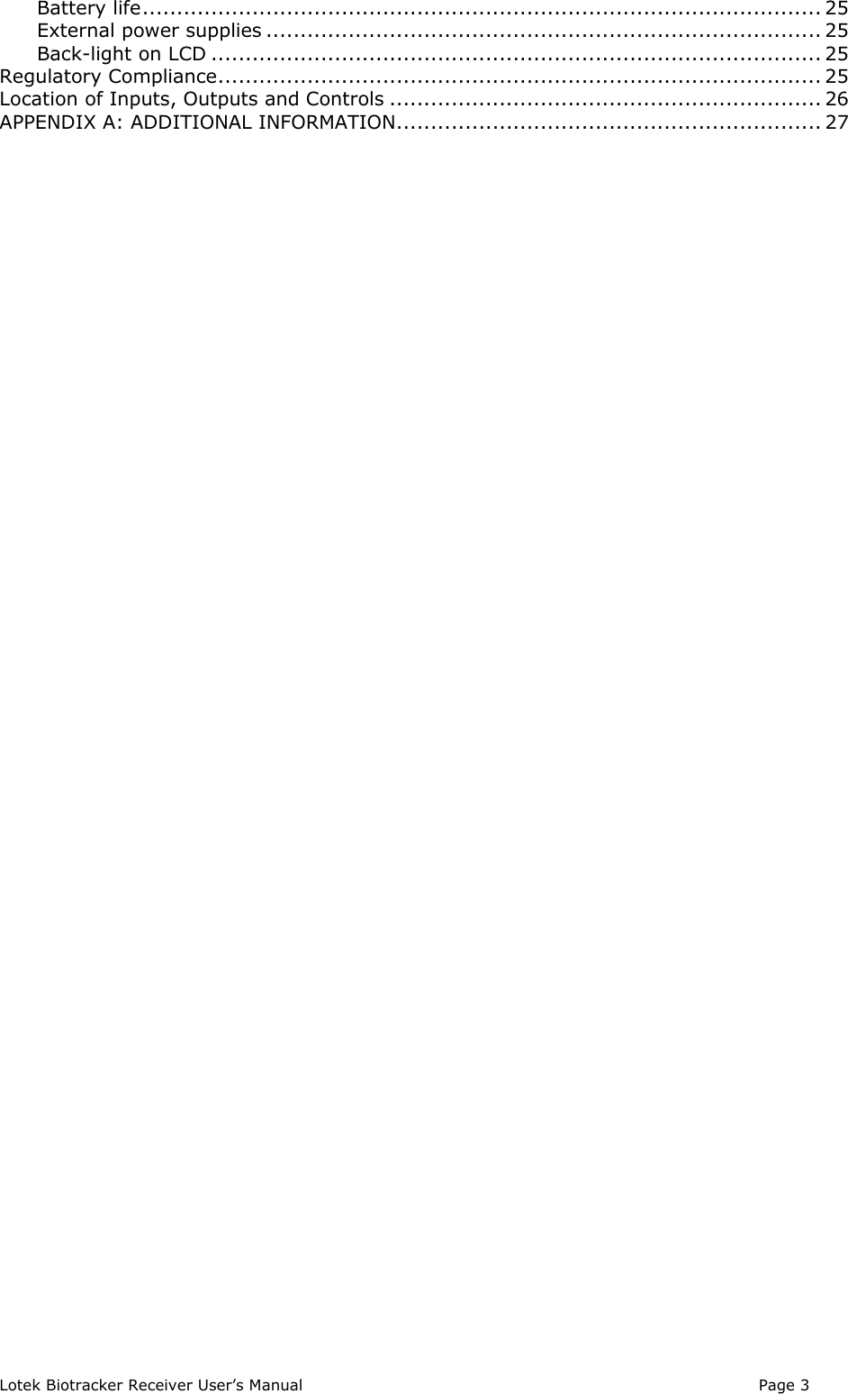
![Lotek Biotracker Receiver User’s Manual Page 5Storing Frequencies in Channels• Start in Frequency mode and tune to the frequency to be stored• Press [Store] to display the last used channel on the top line of the display• Choose a channel using the up/down arrow keys, or enter a channel numberfollowed by [].• Press [Store] to save the frequency to the channel displayed on the top line. Thereceiver will then be in Channel Mode on the chosen channel.Scanning Mode• Press [SCAN] to enter Scanning Mode. Two opposing curved arrows are shown onthe bottom right of the display. The top line shows the scan interval in seconds.• Choose a scan interval by using the arrow keys or typing a number (up to 999).Press [] to accept.• Press [] again to display channels on top line of the display. Channels that areselected for scanning show ‘SC’ in the top right of display.• Toggle channel selection status (‘SC’) on/off by pressing []. Scroll through channelsusing the arrow keys or type a channel number followed by [] to see otherchannels.• To select all channels for scanning, press [DEL]. Pressing [DEL] again deselects allchannels without affecting individual channel selection status (‘SC’). When allchannels are selected for scanning, ‘AC’ is displayed.• To start scanning press [SCAN].• To stop scanning and return to the mode and frequency settings prior to scanningpress [X].• To stop scanning and return to Channel Mode with last channel scanned press[SCAN].](https://usermanual.wiki/Lotek-Wireless/BIOTRACKER/User-Guide-865317-Page-5.png)
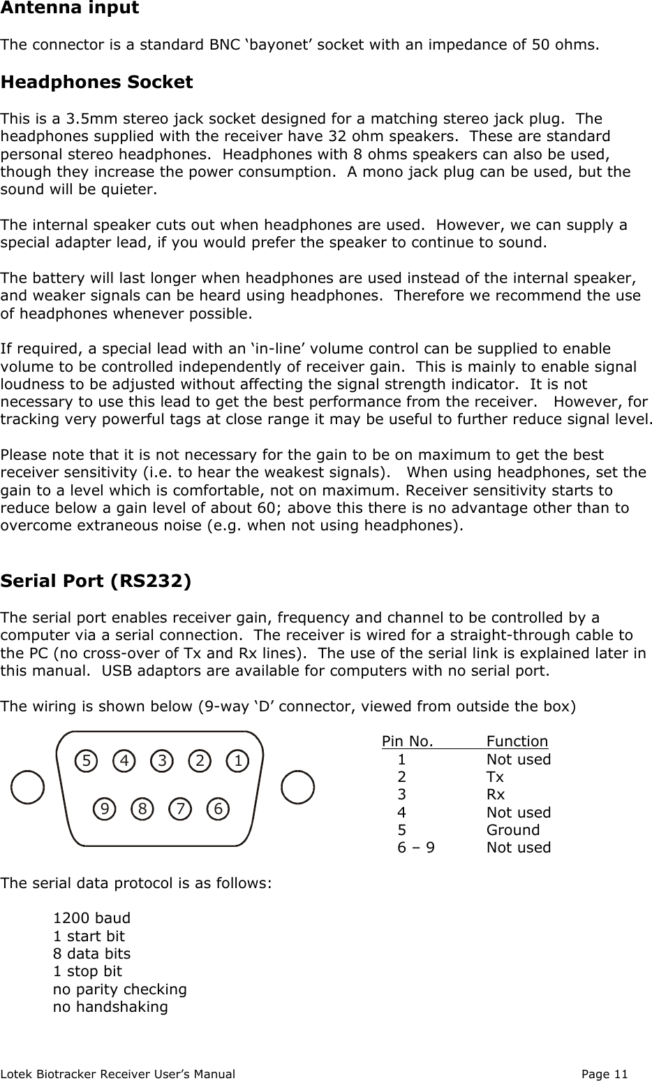
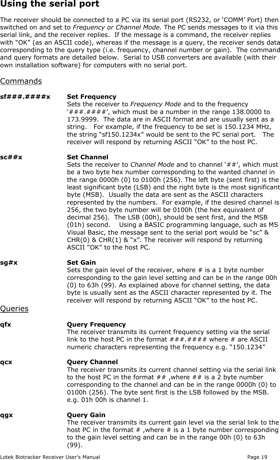
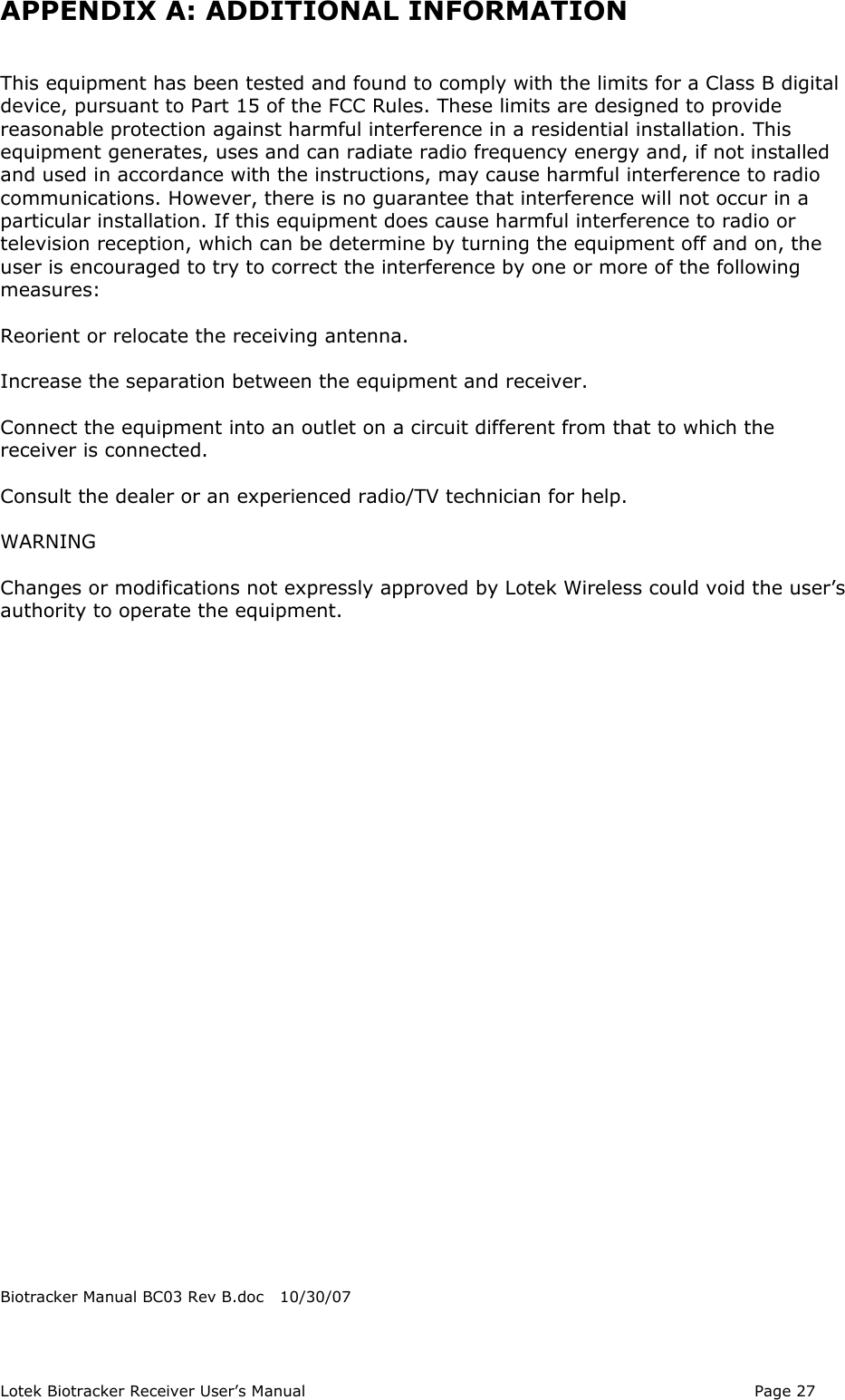
![Page 6 Lotek Biotracker Receiver User’s ManualTop Panel ControlsThis section explains in detail the function of individual keys.PowerHold this key down for one second or more to switch the receiver on or off.When the receiver is switched on it returns to the state it was in when it waslast switched off. It remembers mode, digital gain level, step size andfrequency or channel. All memory contents are also retained.LCD BacklightThis key switches the LCD back-light on and off. The back-light increasesreceiver power consumption (and reduces battery life) by around 50%. Toconserve power if the light is accidentally switched on, the light switches offautomatically after about 4 minutes.Up/Down ArrowsThese keys are used to change frequency or channel, depending on which modethe receiver is in.When in Frequency Mode (‘F’ displayed in bottom right of LCD), the frequencydisplayed on the bottom row of the LCD is changed in either 0.1 kHz or 1kHzsteps. Pressing the key marked [.000/.0000] toggles between the step sizes(tuning resolution).In Channel Mode (‘C’ displayed in bottom right of LCD), the arrow keys step throughoccupied channels displayed on the bottom row of the LCD. Empty channels are notdisplayed. After pressing [STORE], the up/down keys step through all channelsdisplayed in the top row of the LCD, including empty ones.In Scan Mode (two opposing curved arrows displayed in bottom right of LCD), and whenscan interval is displayed in the top row of the LCD, the up/down keys change the scaninterval. After setting the scan interval, the up/down keys step through occupiedchannels. Empty channels are not displayed.Mode SelectionThis toggles between Frequency Mode and Channel Mode. When returning fromChannel Mode to Frequency Mode the frequency displayed is that of the lastchannel selected. The default tuning resolution (step size) is set to 0.1 kHz.Tuning ResolutionThis key toggles between displaying the frequency to the nearest 0.1 kHz (fourdecimal places) or to the nearest 1 kHz (three decimal places). It operates onlyin Frequency Mode.Digital Gain/Volume Control KeysThe keys with loudspeaker symbols control the radio frequency (RF) gain andaudio gain (volume) of the receiver. The upper key increases gain and thelower one reduces it. The gain level is indicated by the number between 0 and99 in the bottom right of the LCD, immediately before the mode symbol.These are known as ‘digital gain keys’ because they set gain in discrete steps.Gain can also be controlled using a knob on the front of the receiver. The knob controlsgain in an analogue fashion within the limits set by digital keys gain (i.e. up to the levelshown on the LCD). It does not change the number displayed in the LCD. Settingthe gain to 99 (maximum) using the digital keys enables the knob to cover the entiregain range.](https://usermanual.wiki/Lotek-Wireless/BIOTRACKER/User-Guide-865317-Page-6.png)
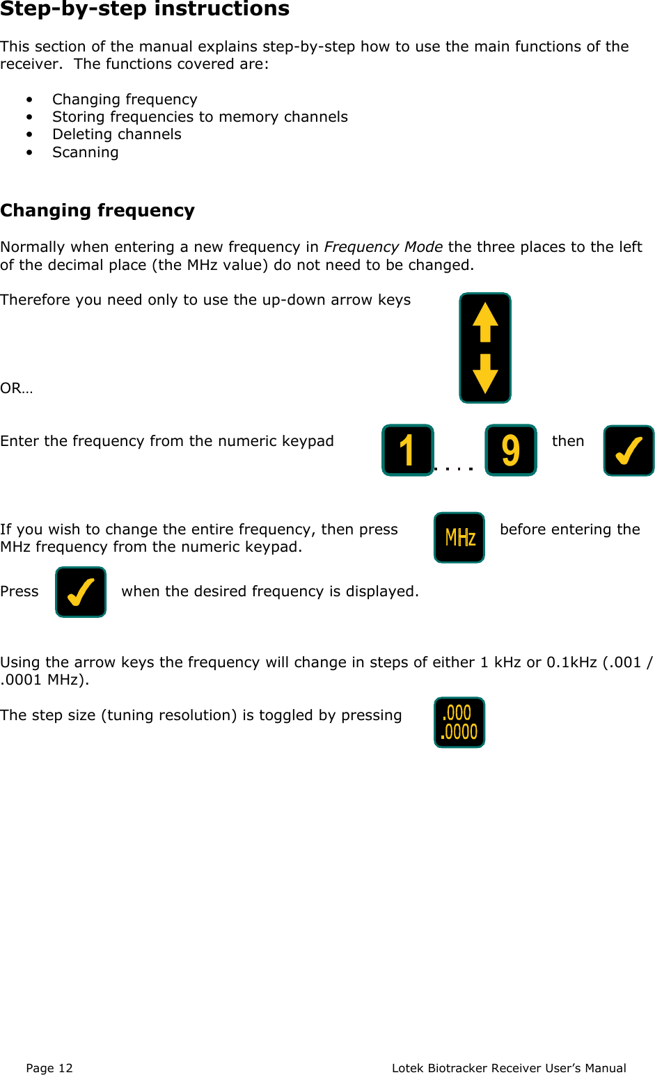
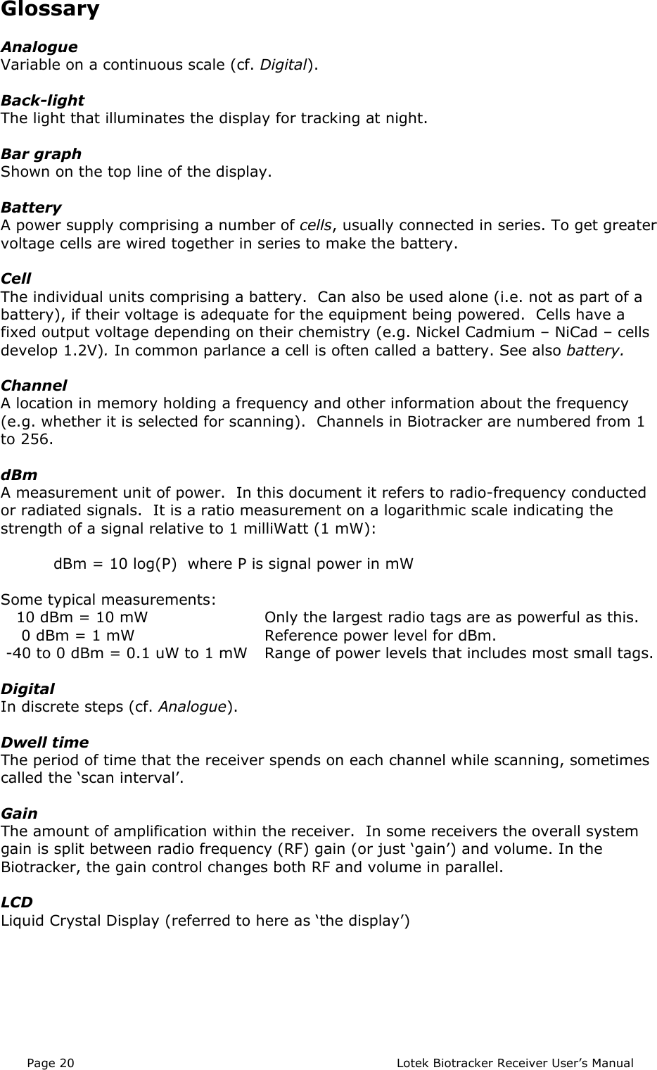
![Lotek Biotracker Receiver User’s Manual Page 7generally the digital keys are used for setting gain to a particular, repeatable level(displayed on the LCD). For normal tracking situations, where it is not necessary toknow the exact gain level, the knob allows both faster and finer control of gain.ScanningThis key puts the receiver into Scan Mode. The top row of the LCD displays‘INTERVAL’ and a number between 001 and 999. This is the period in secondsthe receiver dwells on each selected channel when scanning. The number canbe entered directly via the numeric key pad, or increased/decreased using the arrowkeys. When the desired interval is displayed, press [] to set it.Once the scan interval has been set, the LCD top row displays occupied channels andindicates whether they are selected for scanning. The information displayed isfrequency, channel number and, for channels that are selected, the letters ‘SC’ or ‘AC’.These indicate whether selected channels (SC) or all channels (AC) are to be scanned.If a channel is not selected for scanning, only the frequency and channel number aredisplayed. When scanning starts, these channels will be excluded. To select or deselecta channel, press [] which toggles channel selection. Do not press [] to deselect achannel, as this cancels Scan Mode. To toggle the selection/deselection of all channels(AC) press [DEL]. Use the arrow keys to step through channels for selection.When the channels to be scanned have been chosen, pressing [SCAN] starts thereceiver scanning. The bottom row of the LCD displays the frequency and number of thechannel currently being scanned, the gain level and the symbol for scan mode (curvedopposing arrows). The top line of the LCD displays signal strength and ‘AC’ or ‘SC’,depending on whether all channels (AC) or selected channels only (SC) are beingscanned.To cancel Scan Mode during scanning, press [SCAN], which returns to Channel Modewith last channel scanned, or [], which returns to the mode and frequency settingsprior scanning.Store in MemoryWhen pressed in Frequency Mode or Channel Mode this key displays the lastused channel on the top row of the LCD. The channel number can be set eitherwith the arrow keys, or by entering a number directly from the numeric keypad.If entered from the keypad, [] must be pressed to set the channel. Pressing [STORE]a second time puts the currently displayed frequency on the bottom row into the channeldisplayed on the top row. The receiver is then returned to Channel Mode with the newchannel displayed in the bottom row.The main use for [STORE] is to add new channels or change frequencies in existingchannels. Some typical sequences are shown below to illustrate this.To add a new frequency to a new channel:1. In Frequency Mode, tune to the frequency you wish to store in a channel.2. Press [STORE] to display a channel on the top row of the LCD.3. Select the channel in which you want the frequency to the stored (either using thearrow keys or by direct entry via the numeric keypad followed by []).4. Press [STORE] again to set the frequency in the chosen channel and automaticallyswitch to Channel Mode with the new channel displayed.To change the frequency of an existing channel:1. In Channel Mode select the channel to be changed.2. Press [F/C] to change to Frequency Mode.](https://usermanual.wiki/Lotek-Wireless/BIOTRACKER/User-Guide-865317-Page-7.png)
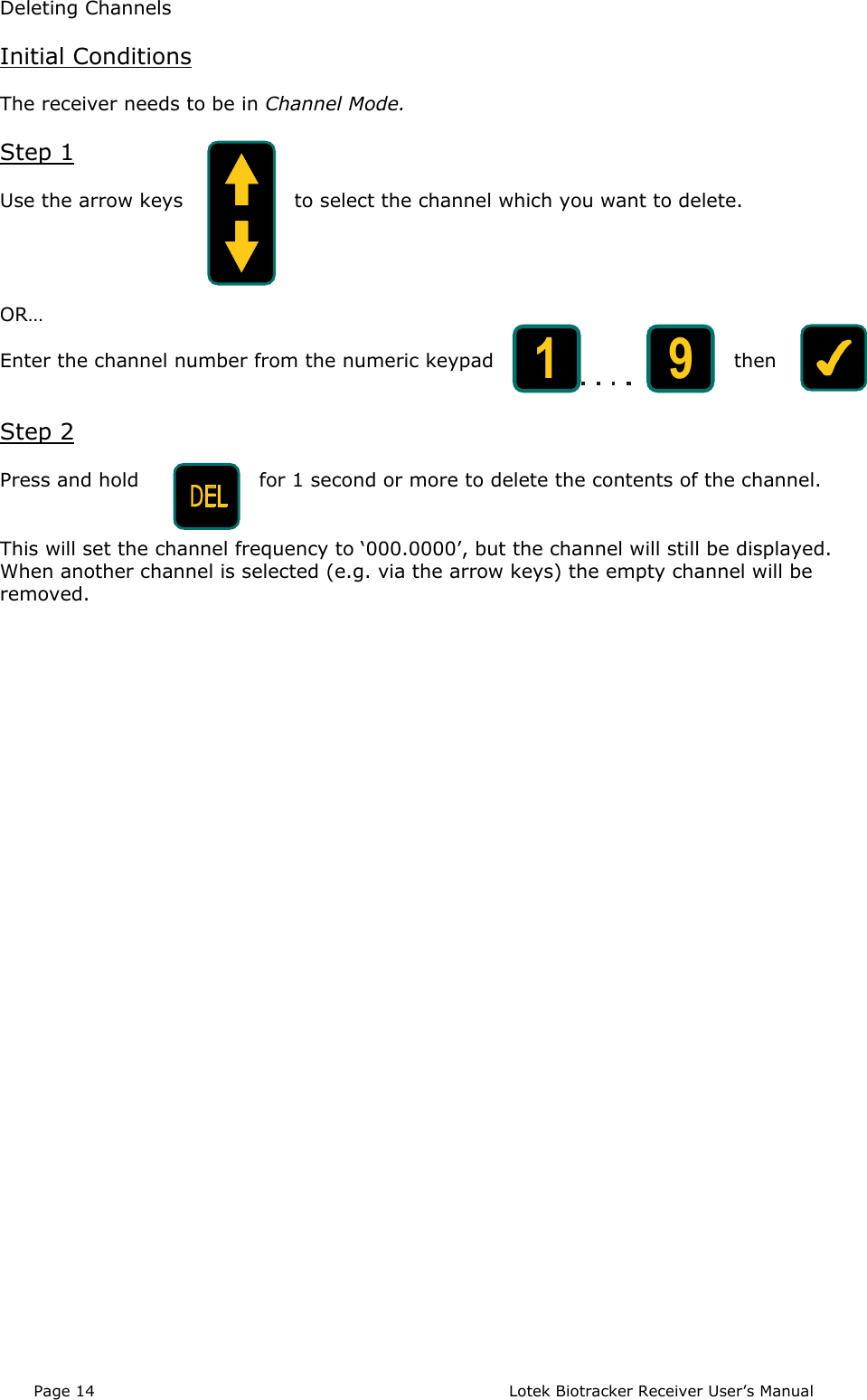
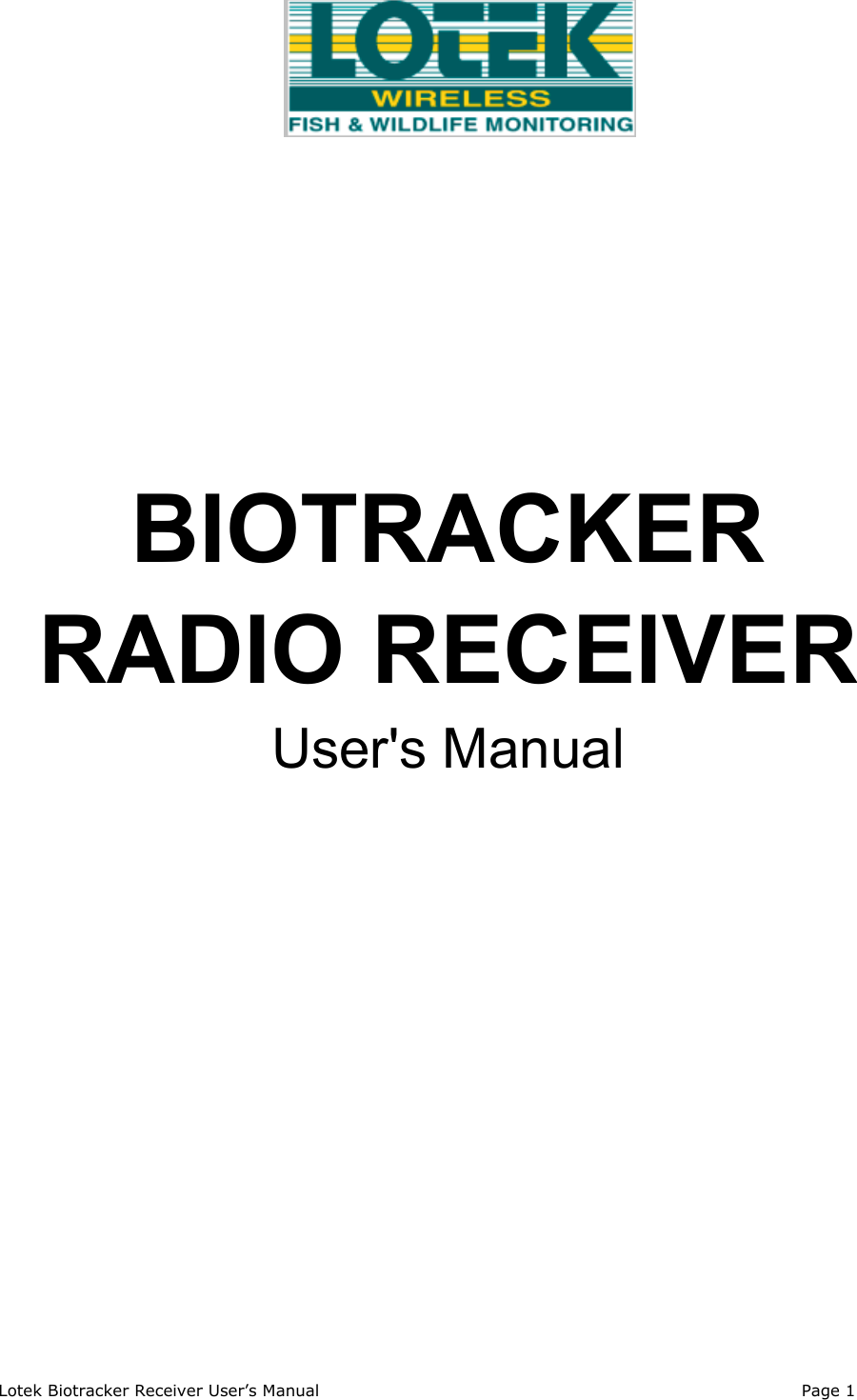
![Page 8 Lotek Biotracker Receiver User’s Manual3. Change the frequency (either using the arrow keys or by direct entry via the numerickeypad followed by [])5. Press [STORE] to display the channel on the top row of the LCD.6. Press [STORE] again to set the new frequency in the channel and automaticallyswitch back to Channel Mode with the new frequency displayed.Change MHzThis key allows the MHz frequency to be changed in Frequency Mode. Afterpressing [MHz] the first placeholder of the MHz frequency will flash and a new3-digit number can be inserted from the numeric keypad. After inserting 3digits the cursor moves to the first decimal place and the kHz frequencies can also bechanged if required. Pressing [] at any time selects the new frequency. Pressing []cancels any changes and returns to the previous state.If a number below than the lower frequency limit or above the upper frequency limit isentered, an ‘OUT OF RANGE’ message is displayed on the top row of the LCD. Enter avalid frequency or press [] to return to the previous one.DeleteThe delete key has three separate functions.The main function, in Channel Mode, is to delete the contents of a channel. To do this,display the channel to be deleted, then hold the [DEL] key down for 1 second.Alternatively, press [STORE] to display a channel on the top row of the LCD. Displaythe channel you want to delete and press [DEL] to delete it and return to Channel Mode.The second function of the delete key is to delete characters under the cursor duringfrequency or channel editing via the numeric keypad.The third, and least intuitive, function of [DEL] is to toggle the selection/deselection ofall channels for scanning in scan mode (AC). When selecting channels for scanning,[] toggles selection of individual channels (displaying either SC or blank afterfrequency and channel number in the top row of the LCD), whereas [DEL] togglesbetween AC and SC or blank. When AC is shown, all channels are selected for scanning.Pressing [DEL] returns all the channels to their previous state (SC or blank).Numeric KeysThe numeric keypad is used to enter channels or frequencies.When entering channel numbers, new digits are inserted in the right-hand place-holderand shifted left if further characters are added. This is to eliminate the need to enterleading zeros.When entering frequencies, the cursor starts under the left-hand placeholder and movesright as new number are added.AcceptThis key is equivalent to [ENTER] on a computer keyboard. It is used to acceptany changes being made via the numeric keypad.CancelThis is the ‘Cancel’ Key. Pressing it during any editing operation returns thereceiver to the state it was in before the editing operation began. Pressing []in Scan Mode cancels scanning and returns the receiver to its previous mode.19](https://usermanual.wiki/Lotek-Wireless/BIOTRACKER/User-Guide-865317-Page-8.png)