Lotek Wireless BIOTRACKER Telemetry Receiver User Manual BC03 Biotracker Manual Rev B
Lotek Wireless, Inc Telemetry Receiver BC03 Biotracker Manual Rev B
user manual

Lotek Biotracker Receiver User’s Manual Page 1
BIOTRACKER
RADIO RECEIVER
User's Manual
Page 2 Lotek Biotracker Receiver User’s Manual
Contents
Quick Start Guide................................................................................................. 4
Description of receiver operation ......................................................................... 4
Basic Functions ................................................................................................. 4
Frequency Mode................................................................................................ 4
Channel Mode................................................................................................... 4
Storing Frequencies in Channels .......................................................................... 5
Scanning Mode ................................................................................................. 5
Top Panel Controls ............................................................................................... 6
Power ........................................................................................................... 6
LCD Backlight ................................................................................................ 6
Up/Down Arrows ............................................................................................ 6
Mode Selection............................................................................................... 6
Tuning Resolution ........................................................................................... 6
Digital Gain/Volume Control Keys...................................................................... 6
Scanning ....................................................................................................... 7
Store in Memory............................................................................................. 7
Change MHz .................................................................................................. 8
Delete........................................................................................................... 8
Numeric Keys................................................................................................. 8
Accept .......................................................................................................... 8
Cancel .......................................................................................................... 8
Liquid Crystal Display (LCD)................................................................................ 9
Signal Strength Display ................................................................................... 9
Battery State Indicator.................................................................................... 9
Front Panel Connectors and Controls..................................................................... 10
Gain Control Knob ........................................................................................ 10
Battery Charger and External Power Socket...................................................... 10
Charging LED............................................................................................... 10
Antenna input .............................................................................................. 11
Headphones Socket ...................................................................................... 11
Serial Port (RS232)....................................................................................... 11
Step-by-step instructions .................................................................................... 12
Changing frequency......................................................................................... 12
Storing frequencies to memory (channels) .......................................................... 13
Scanning........................................................................................................ 15
Receiver Use ..................................................................................................... 17
Tracking in wet weather ................................................................................... 17
Batteries ........................................................................................................ 17
Trouble-shooting................................................................................................ 18
Charging Problems .......................................................................................... 18
Battery cover bolts .......................................................................................... 18
Using the serial port ........................................................................................... 19
Glossary ........................................................................................................... 20
Biotracker Specifications ..................................................................................... 22
Summary Specifications Table........................................................................... 22
Full Specifications Table ................................................................................... 23
Specification ................................................................................................ 23
Frequency Bands .......................................................................................... 23
Sensitivity ................................................................................................... 23
Selectivity ................................................................................................... 23
Gain Control Range....................................................................................... 23
Channels ..................................................................................................... 23
Scanning ..................................................................................................... 24
Weight ........................................................................................................ 24
Waterproofing .............................................................................................. 24
Frequency Stability ....................................................................................... 24
Tuning ........................................................................................................ 25
Lotek Biotracker Receiver User’s Manual Page 3
Battery life................................................................................................... 25
External power supplies ................................................................................. 25
Back-light on LCD ......................................................................................... 25
Regulatory Compliance........................................................................................ 25
Location of Inputs, Outputs and Controls ............................................................... 26
APPENDIX A: ADDITIONAL INFORMATION.............................................................. 27
Page 4 Lotek Biotracker Receiver User’s Manual
Quick Start Guide
Before first use, we recommend you put the Biotracker on charge. The battery is fully-
charged when the receiver is manufactured, but rechargeable batteries self-discharge
slowly over time and after any period of storage will not be at full capacity.
Description of receiver operation
The receiver has three modes: Frequency, Channel and Scan.
Frequency Mode: Frequency is set directly via the numeric keypad or arrow keys.
Channel Mode: Channels holding stored frequencies are selected via the numeric
keypad or arrow keys. There are 256 channels.
Scan Mode: The receiver steps in numerical sequence through all channels or
selected channels only.
Basic Functions
• To turn the receiver on and off hold [ON/OFF] down for at least a second.
• To toggle between Frequency and Channel Mode (shown by ‘F’ or ‘C’ in bottom right
corner of display) press [F/C].
• [X] cancels the current operation.
• [
] enters the current number (channel, frequency etc) or completes the current
operation.
• [DEL] deletes the character at current cursor position. To delete the contents of a
channel in Channel Mode hold the button down for more than a second.
• The key with the light bulb symbol toggles the display back-light on and off. The light
switches off automatically after about 4 minutes.
• To adjust receiver gain, use the keys with loudspeaker symbols. The gain level (00 to
99) is displayed next to the mode indicator on the bottom row of the LCD. Gain can
also be adjusted (up to the limit shown in the display) using the gain knob. The knob
does not change the gain level displayed on the LCD.
• Signal strength is displayed on the top line of the LCD as a horizontal bar graph, and
the peak signal value is displayed on the top right. The peak value is held on the
display for 1 second or updated if another signal is received sooner.
Frequency Mode
• In Frequency Mode ‘F’ is displayed in the bottom right corner of the display.
• Typing a number enters the kHz frequency units (numbers after the decimal point).
Press [
] to set the frequency or [X] to cancel and revert back to the previous
frequency.
• To change the MHz frequency (numbers before the decimal point) press [MHz].
Enter the MHz frequency and press [
] to set or [X] to cancel.
• The up/down arrows tune the frequency one step at a time, at the current tuning
resolution (1 kHz or 0.1 kHz).
• The tuning resolution is toggled between 1 kHz and 0.1 kHz by the key
marked [.000 / .0000].
Channel Mode
• In Channel Mode ‘C’ is displayed in bottom right corner of display.
• The up/down arrows step through stored channels in the receiver’s memory.
• Channels can also be recalled by entering a channel number. Press [
] to set
or [X] to cancel.
• To delete the contents of a channel, press [DEL] for a second or more.
Lotek Biotracker Receiver User’s Manual Page 5
Storing Frequencies in Channels
• Start in Frequency mode and tune to the frequency to be stored
• Press [Store] to display the last used channel on the top line of the display
• Choose a channel using the up/down arrow keys, or enter a channel number
followed by [
].
• Press [Store] to save the frequency to the channel displayed on the top line. The
receiver will then be in Channel Mode on the chosen channel.
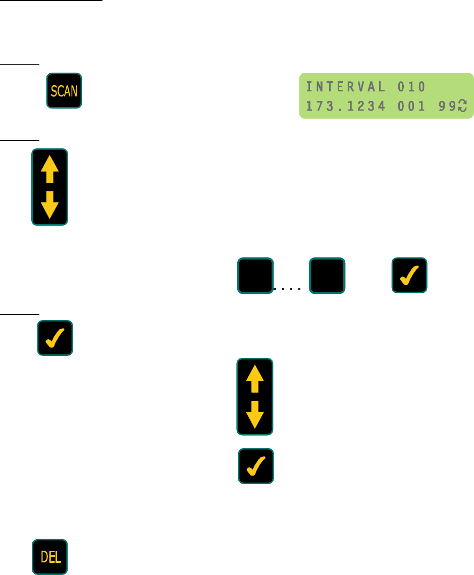
Scanning Mode
• Press [SCAN] to enter Scanning Mode. Two opposing curved arrows are shown on
the bottom right of the display. The top line shows the scan interval in seconds.
• Choose a scan interval by using the arrow keys or typing a number (up to 999).
Press [
] to accept.
• Press [
] again to display channels on top line of the display. Channels that are
selected for scanning show ‘SC’ in the top right of display.
• Toggle channel selection status (‘SC’) on/off by pressing [
]. Scroll through channels
using the arrow keys or type a channel number followed by [
] to see other
channels.
• To select all channels for scanning, press [DEL]. Pressing [DEL] again deselects all
channels without affecting individual channel selection status (‘SC’). When all
channels are selected for scanning, ‘AC’ is displayed.
• To start scanning press [SCAN].
• To stop scanning and return to the mode and frequency settings prior to scanning
press [X].
• To stop scanning and return to Channel Mode with last channel scanned press
[SCAN].

Page 6 Lotek Biotracker Receiver User’s Manual
Top Panel Controls
This section explains in detail the function of individual keys.
Power
Hold this key down for one second or more to switch the receiver on or off.
When the receiver is switched on it returns to the state it was in when it was
last switched off. It remembers mode, digital gain level, step size and
frequency or channel. All memory contents are also retained.
LCD Backlight
This key switches the LCD back-light on and off. The back-light increases
receiver power consumption (and reduces battery life) by around 50%. To
conserve power if the light is accidentally switched on, the light switches off
automatically after about 4 minutes.
Up/Down Arrows
These keys are used to change frequency or channel, depending on which mode
the receiver is in.
When in Frequency Mode (‘F’ displayed in bottom right of LCD), the frequency
displayed on the bottom row of the LCD is changed in either 0.1 kHz or 1kHz
steps. Pressing the key marked [.000/.0000] toggles between the step sizes
(tuning resolution).
In Channel Mode (‘C’ displayed in bottom right of LCD), the arrow keys step through
occupied channels displayed on the bottom row of the LCD. Empty channels are not
displayed. After pressing [STORE], the up/down keys step through all channels
displayed in the top row of the LCD, including empty ones.
In Scan Mode (two opposing curved arrows displayed in bottom right of LCD), and when
scan interval is displayed in the top row of the LCD, the up/down keys change the scan
interval. After setting the scan interval, the up/down keys step through occupied
channels. Empty channels are not displayed.
Mode Selection
This toggles between Frequency Mode and Channel Mode. When returning from
Channel Mode to Frequency Mode the frequency displayed is that of the last
channel selected. The default tuning resolution (step size) is set to 0.1 kHz.
Tuning Resolution
This key toggles between displaying the frequency to the nearest 0.1 kHz (four
decimal places) or to the nearest 1 kHz (three decimal places). It operates only
in Frequency Mode.
Digital Gain/Volume Control Keys
The keys with loudspeaker symbols control the radio frequency (RF) gain and
audio gain (volume) of the receiver. The upper key increases gain and the
lower one reduces it. The gain level is indicated by the number between 0 and
99 in the bottom right of the LCD, immediately before the mode symbol.
These are known as ‘digital gain keys’ because they set gain in discrete steps.
Gain can also be controlled using a knob on the front of the receiver. The knob controls
gain in an analogue fashion within the limits set by digital keys gain (i.e. up to the level
shown on the LCD). It does not change the number displayed in the LCD. Setting
the gain to 99 (maximum) using the digital keys enables the knob to cover the entire
gain range.

Lotek Biotracker Receiver User’s Manual Page 7
generally the digital keys are used for setting gain to a particular, repeatable level
(displayed on the LCD). For normal tracking situations, where it is not necessary to
know the exact gain level, the knob allows both faster and finer control of gain.
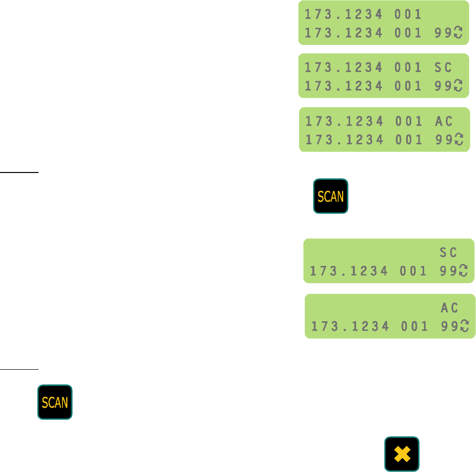
Scanning
This key puts the receiver into Scan Mode. The top row of the LCD displays
‘INTERVAL’ and a number between 001 and 999. This is the period in seconds
the receiver dwells on each selected channel when scanning. The number can
be entered directly via the numeric key pad, or increased/decreased using the arrow
keys. When the desired interval is displayed, press [
] to set it.
Once the scan interval has been set, the LCD top row displays occupied channels and
indicates whether they are selected for scanning. The information displayed is
frequency, channel number and, for channels that are selected, the letters ‘SC’ or ‘AC’.
These indicate whether selected channels (SC) or all channels (AC) are to be scanned.
If a channel is not selected for scanning, only the frequency and channel number are
displayed. When scanning starts, these channels will be excluded. To select or deselect
a channel, press [
] which toggles channel selection. Do not press [
] to deselect a
channel, as this cancels Scan Mode. To toggle the selection/deselection of all channels
(AC) press [DEL]. Use the arrow keys to step through channels for selection.
When the channels to be scanned have been chosen, pressing [SCAN] starts the
receiver scanning. The bottom row of the LCD displays the frequency and number of the
channel currently being scanned, the gain level and the symbol for scan mode (curved
opposing arrows). The top line of the LCD displays signal strength and ‘AC’ or ‘SC’,
depending on whether all channels (AC) or selected channels only (SC) are being
scanned.
To cancel Scan Mode during scanning, press [SCAN], which returns to Channel Mode
with last channel scanned, or [
], which returns to the mode and frequency settings
prior scanning.
Store in Memory
When pressed in Frequency Mode or Channel Mode this key displays the last
used channel on the top row of the LCD. The channel number can be set either
with the arrow keys, or by entering a number directly from the numeric keypad.
If entered from the keypad, [
] must be pressed to set the channel. Pressing [STORE]
a second time puts the currently displayed frequency on the bottom row into the channel
displayed on the top row. The receiver is then returned to Channel Mode with the new
channel displayed in the bottom row.
The main use for [STORE] is to add new channels or change frequencies in existing
channels. Some typical sequences are shown below to illustrate this.
To add a new frequency to a new channel:
1. In Frequency Mode, tune to the frequency you wish to store in a channel.
2. Press [STORE] to display a channel on the top row of the LCD.
3. Select the channel in which you want the frequency to the stored (either using the
arrow keys or by direct entry via the numeric keypad followed by [
]).
4. Press [STORE] again to set the frequency in the chosen channel and automatically
switch to Channel Mode with the new channel displayed.
To change the frequency of an existing channel:
1. In Channel Mode select the channel to be changed.
2. Press [F/C] to change to Frequency Mode.

Page 8 Lotek Biotracker Receiver User’s Manual
3. Change the frequency (either using the arrow keys or by direct entry via the numeric
keypad followed by [
])
5. Press [STORE] to display the channel on the top row of the LCD.
6. Press [STORE] again to set the new frequency in the channel and automatically
switch back to Channel Mode with the new frequency displayed.
Change MHz
This key allows the MHz frequency to be changed in Frequency Mode. After
pressing [MHz] the first placeholder of the MHz frequency will flash and a new
3-digit number can be inserted from the numeric keypad. After inserting 3
digits the cursor moves to the first decimal place and the kHz frequencies can also be
changed if required. Pressing [
] at any time selects the new frequency. Pressing [
]
cancels any changes and returns to the previous state.
If a number below than the lower frequency limit or above the upper frequency limit is
entered, an ‘OUT OF RANGE’ message is displayed on the top row of the LCD. Enter a
valid frequency or press [
] to return to the previous one.
Delete
The delete key has three separate functions.
The main function, in Channel Mode, is to delete the contents of a channel. To do this,
display the channel to be deleted, then hold the [DEL] key down for 1 second.
Alternatively, press [STORE] to display a channel on the top row of the LCD. Display
the channel you want to delete and press [DEL] to delete it and return to Channel Mode.
The second function of the delete key is to delete characters under the cursor during
frequency or channel editing via the numeric keypad.
The third, and least intuitive, function of [DEL] is to toggle the selection/deselection of
all channels for scanning in scan mode (AC). When selecting channels for scanning,
[
] toggles selection of individual channels (displaying either SC or blank after
frequency and channel number in the top row of the LCD), whereas [DEL] toggles
between AC and SC or blank. When AC is shown, all channels are selected for scanning.
Pressing [DEL] returns all the channels to their previous state (SC or blank).
Numeric Keys
The numeric keypad is used to enter channels or frequencies.
When entering channel numbers, new digits are inserted in the right-hand place-holder
and shifted left if further characters are added. This is to eliminate the need to enter
leading zeros.
When entering frequencies, the cursor starts under the left-hand placeholder and moves
right as new number are added.
Accept
This key is equivalent to [ENTER] on a computer keyboard. It is used to accept
any changes being made via the numeric keypad.
Cancel
This is the ‘Cancel’ Key. Pressing it during any editing operation returns the
receiver to the state it was in before the editing operation began. Pressing [
]
in Scan Mode cancels scanning and returns the receiver to its previous mode.
1
9
Lotek Biotracker Receiver User’s Manual Page 9
Liquid Crystal Display (LCD)
The LCD has two rows with 16 character places per row. The diagrams below show the
position of information displayed in different modes.
LCD Functions in Frequency Mode or Channel Mode
LCD Functions in Scanning Mode
Signal Strength Display
The Lotek Biotracker Receiver displays signal strength in two ways: using a bar graph
and a number. Both indicators are displayed on the top line of the LCD. The system
responds to pulses over 10 ms long and above a threshold, so under normal
circumstances noise is ignored. The display is held for 1 second after triggering
(otherwise pulses would be too short to see). If the display is constantly being triggered
by noise, the pulses are likely to be missed.
The display can be changed by adjusting the gain. If there is too much noise and it is
triggering the display, turn the gain down. Similarly, reduce gain if the signal is causing
the bar graph to swing full scale (and the number displayed is 99).
Battery State Indicator
The empty battery symbol in the top right of the LCD indicates when the battery needs to
be recharged. When the battery is OK this symbol is NOT shown; it only appears when
the battery has about 10% of its capacity remaining. There is no ‘full battery’ symbol.
Selection of
channels for
scanning
Channel to
be scanned
All
channels
Selected
channels
Channel
not selected
Frequency in MHz
0.1 kHz
resolution In Channel Mode
only. 001 to 256
Signal Strength
Bar Chart
1 kHz
resolution
Gain
(01 to 99)
Signal Strength
Battery Low
Relative scale
(01 to 99)
Mode
Channel
Number
Channel
Mode
Scanning
Mode
Frequency
Mode
Page 10 Lotek Biotracker Receiver User’s Manual
Front Panel Connectors and Controls
Gain Control Knob
Receiver gain is controlled by two keys (marked with loudspeaker symbols) on the
keypad and by a knob on the front of the box. The keypad controls are digital and set
gain to a level shown in the LCD as a whole number between 0 and 99. The knob also
controls gain, but on a continuum between zero and the value shown in the LCD. The
knob does not change the gain level number displayed on the LCD.
Setting gain to 99 using the keypad allows the full gain range to be controlled by the
knob. Setting digital gain to a lower level prevents higher gains being accessible via the
knob, and gives finer control over the available gain range. The main benefit of using
the knob to control receiver gain is that it is quicker to move through the gain range.
The potentiometer under the gain control knob is hermetically sealed, as is its hole in the
receiver box. Unlike analogue controls on most electronic equipment, it is completely
waterproof.
Battery Charger and External Power Socket
Charging must be done in an ambient temperature between 5 and 35°C. This is because
there is a thermal cut-out in the charging circuit to prevent over-charging of the battery
cells (over-charging cells can damage them). The thermal cut-out threshold is set to
50°C, but the heat generated by the charging process can cause this threshold to be
reached in ambient temperatures above 35°C.
The charging state is shown by an LED next to the charging socket. It flashes red during
battery charging and steady green when charging is complete.
The receiver will not be harmed if the external power supply is left attached after
charging is complete, but still it is good practice not to leave the power supply connected
for longer than necessary.
Only the special NiMH 4A battery pack supplied with the receiver can be charged inside
the receiver. The receiver prevents any other form of battery being connected to the
internal charging circuit. This is mainly to safeguard against charging non-rechargeable
(i.e. primary) cells, because if charged they may explode!
If other rechargeable cells are used (i.e. with the AA battery holder supplied), they need
to be charged independently with a separate AA-size battery charger.
Charging LED
This LED flashes red during battery charging and steady green when charging is
complete.

Lotek Biotracker Receiver User’s Manual Page 11
Antenna input
The connector is a standard BNC ‘bayonet’ socket with an impedance of 50 ohms.
Headphones Socket
This is a 3.5mm stereo jack socket designed for a matching stereo jack plug. The
headphones supplied with the receiver have 32 ohm speakers. These are standard
personal stereo headphones. Headphones with 8 ohms speakers can also be used,
though they increase the power consumption. A mono jack plug can be used, but the
sound will be quieter.
The internal speaker cuts out when headphones are used. However, we can supply a
special adapter lead, if you would prefer the speaker to continue to sound.
The battery will last longer when headphones are used instead of the internal speaker,
and weaker signals can be heard using headphones. Therefore we recommend the use
of headphones whenever possible.
If required, a special lead with an ‘in-line’ volume control can be supplied to enable
volume to be controlled independently of receiver gain. This is mainly to enable signal
loudness to be adjusted without affecting the signal strength indicator. It is not
necessary to use this lead to get the best performance from the receiver. However, for
tracking very powerful tags at close range it may be useful to further reduce signal level.
Please note that it is not necessary for the gain to be on maximum to get the best
receiver sensitivity (i.e. to hear the weakest signals). When using headphones, set the
gain to a level which is comfortable, not on maximum. Receiver sensitivity starts to
reduce below a gain level of about 60; above this there is no advantage other than to
overcome extraneous noise (e.g. when not using headphones).
Serial Port (RS232)
The serial port enables receiver gain, frequency and channel to be controlled by a
computer via a serial connection. The receiver is wired for a straight-through cable to
the PC (no cross-over of Tx and Rx lines). The use of the serial link is explained later in
this manual. USB adaptors are available for computers with no serial port.
The wiring is shown below (9-way ‘D’ connector, viewed from outside the box)
Pin No. Function
1 Not used
2 Tx
3 Rx
4 Not used
5 Ground
6 – 9 Not used
The serial data protocol is as follows:
1200 baud
1 start bit
8 data bits
1 stop bit
no parity checking
no handshaking
1
2
6
3
7
4
8
5
9
Page 12 Lotek Biotracker Receiver User’s Manual
Step-by-step instructions
This section of the manual explains step-by-step how to use the main functions of the
receiver. The functions covered are:
• Changing frequency
• Storing frequencies to memory channels
• Deleting channels
• Scanning
Changing frequency
Normally when entering a new frequency in Frequency Mode the three places to the left
of the decimal place (the MHz value) do not need to be changed.
Therefore you need only to use the up-down arrow keys
OR…
Enter the frequency from the numeric keypad then
If you wish to change the entire frequency, then press before entering the
MHz frequency from the numeric keypad.
Press when the desired frequency is displayed.
Using the arrow keys the frequency will change in steps of either 1 kHz or 0.1kHz (.001 /
.0001 MHz).
The step size (tuning resolution) is toggled by pressing
1
9
Lotek Biotracker Receiver User’s Manual Page 13
Storing frequencies to memory (channels)
The receiver has 256 memory channels to which you can save frequencies.
Initial Conditions
The receiver needs to be in Frequency Mode, and set to
the frequency you wish to store.
Step 1
Press to display the last used channel
on the top row.
Step 2
Use to select the channel in which you want to
store the frequency.
OR…
Enter the channel number from the numeric keypad then
Step 3
Press to save the frequency in the chosen channel.
The receiver will revert to Channel Mode with the stored
channel selected.
Software to enable channel frequencies to be uploaded via a serial or USB port from a PC
is available.
1
9
Page 14 Lotek Biotracker Receiver User’s Manual
Deleting Channels
Initial Conditions
The receiver needs to be in Channel Mode.
Step 1
Use the arrow keys to select the channel which you want to delete.
OR…
Enter the channel number from the numeric keypad then
Step 2
Press and hold for 1 second or more to delete the contents of the channel.
This will set the channel frequency to ‘000.0000’, but the channel will still be displayed.
When another channel is selected (e.g. via the arrow keys) the empty channel will be
removed.
1
9
Lotek Biotracker Receiver User’s Manual Page 15
Scanning
The receiver has a Scanning Mode in which selected channels are automatically stepped
through in sequence at a user-definable time interval. There is no facility to
automatically detect signals in this mode (unlike an amateur radio ‘scanner’).
Initial Conditions
The receiver can be in either Frequency Mode or Channel Mode.
The frequencies to be scanned should already be stored in memory.
Step 1
Press to display the scanning interval
(in seconds) on the top line of
the display.
Step 2
Use to select the interval (in seconds, 1 - 999).
OR…
Enter the interval from the numeric keypad then
Step 3
Press to display channels on the top line of the display.
Step through the channels using the arrows
Select or deselect individual channels using
This toggles the channel selection and
shows the selection state in the top right of
the display (SC = channel selected for scanning, or blank = channel not selected).
Use to select or deselect all channels at once. The individual selection status
of each channel is not affected by ‘all channel’ deselection.
1
9
Page 16 Lotek Biotracker Receiver User’s Manual
The following LCD diagrams show the characters displayed for the different selection
states:
Individual channel not selected
Individual channel selected
All channels selected
Step 4
When the channels to be scanned have been selected, press to start the
scanning process.
When only selected channels are being
scanned the top line of the display shows ‘SC’.
When all channels are being scanned the top
line of the display shows ‘AC’.
Step 5
Press to stop scanning and enter Channel Mode with the receiver set to the
last channel scanned.
Alternatively, to stop scanning and enter Channel Mode with the receiver
set to the channel used when the receiver was last in Channel Mode, press
Lotek Biotracker Receiver User’s Manual Page 17
Receiver Use
Tracking in wet weather
You do not need to protect this receiver from the rain. The membrane keypad on the top
panel is completely waterproof, as is the battery compartment lid. All front panel
controls and connectors are sealed on the inside of the receiver box so that water can
not reach the receiver electronics. When they are not in use, the open sockets
(headphones, serial port and charger) should have covers fitted to prevent water
entering them. Spare covers are included with the receiver, and more can be supplied
on request.
If any of the open sockets get wet, please dry them out in air (or with a hair dryer) as
soon as possible.
Batteries
The empty battery symbol in the top right of the LCD indicates when the battery needs to
be recharged. When the battery is OK this symbol is NOT shown. It only appears when
the battery has about 10% of its capacity remaining. There is no ‘full battery’ symbol.
The receiver has a variety of power supply options to suit the needs of any radio-tracking
project. Apart from the external power supply, there is an internal battery which can
take a number of forms. As supplied, the receiver is fitted with a battery pack that can
be recharged from any 12V 500mA DC supply via the external power socket. This
battery pack contains four ‘A’-size Nickel Metal-Hydride (NiMH) cells built in a single
block with a re-settable ‘poly-switch’ and temperature-sensing thermistor to prevent
short-circuit damage and over-charging. It will run the receiver for about 28 hours on a
single charge, and it takes about 10 hours to charge from a completely discharged state.
When facilities for recharging are not available, the 4A battery pack can be replaced by a
holder for four AA cells. The cells used in this holder can be either primary (non-
rechargeable) or rechargeable NiCads or NiMH cells. If rechargeable AA cells are used,
they have to be taken out of the receiver for charging. As a safety feature – to prevent
accidental charging of primary cells which may explode – only the 4A battery pack
supplied with the receiver can be recharged in situ. During battery pack charging the
ambient temperature must be between 5 and 35°C. The battery pack may not charge
fully outside these temperatures.
If you are using the receiver for many hours each day, and have access to a charging
power supply (e.g. mains electricity or a car battery) we recommend that you use the
rechargeable 4A battery pack. If you do not have access to a charging supply, then you
have the choice of primary cells, or rechargeable cells that have to removed from the
receiver for replacement or recharging. The main factors to consider when deciding
whether to use primary or rechargeable cells are: 1) rechargeable cells do not last as
long as primary cells, and 2) rechargeable cells self-discharge at a high rate and thereby
lose their capacity even if not used. If the receiver is used infrequently or for only a
short period (e.g. for a few hours per week) it is better to fit primary cells. Using
rechargeable cells reduces waste.
Remove the battery if the receiver is to be stored for more than 3 months, because the
circuitry draws a very small amount of current even when switched off, and it is good
practice because of the risk of leakage from exhausted primary cells. Rechargeable
batteries that have been stored for 3 months or more should be recharged before use.
This applies even if the battery was fully charged after it was last used, because
rechargeable batteries have a high self-discharge rate.
The receiver memory is retained indefinitely even when the receiver has no battery.
Page 18 Lotek Biotracker Receiver User’s Manual
Trouble-shooting
Charging Problems
There are some special cases where charging may be problematic. The battery in a new
receiver has been charged only once or twice and may not yet have reached its full
capacity. As a result, for the first few charge-discharge cycles, the receiver may not run
for quite as long as expected. Similar problems may occur if the receiver has been
stored for a long time and the battery is deeply discharged. This may also result in the
battery apparently not charging properly (i.e. the green light comes on too soon,
wrongly indicating that the battery is fully charged).
To overcome these charging problems, charge the receiver repeatedly (three or four
times), with an interval of about 30 minutes between charges. There is no need to
discharge the battery between each charging session. Simply unplug the charger when
the green light comes on, wait half an hour, then plug it in again.
Battery cover bolts
A few users have reported loosening of the bolts retaining the battery compartment lid.
We believe this may be caused by the heads of the bolts rubbing on clothing. We
provide spare bolts with each new receiver and we will supply a limited number of further
replacements free of charge.
To prevent the loss of bolts we recommend they are checked periodically to ensure they
remain tight. We are trying to find a long-term solution to this problem, but in the
meantime, if the bolts on your receiver continue to become loose, we suggest covering
them with insulating tape.
Please do not over-tighten the bolts, nor use thread-locking compounds to keep the bolts
in place.

Lotek Biotracker Receiver User’s Manual Page 19
Using the serial port
The receiver should be connected to a PC via its serial port (RS232, or ‘COMM’ Port) then
switched on and set to Frequency or Channel Mode. The PC sends messages to it via this
serial link, and the receiver replies. If the message is a command, the receiver replies
with “OK” (as an ASCII code), whereas if the message is a query, the receiver sends data
corresponding to the query type (i.e. frequency, channel number or gain). The command
and query formats are detailed below. Serial to USB converters are available (with their
own installation software) for computers with no serial port.
Commands
sf###.####x Set Frequency
Sets the receiver to Frequency Mode and to the frequency
‘###.####’, which must be a number in the range 138.0000 to
173.9999. The data are in ASCII format and are usually sent as a
string. For example, if the frequency to be set is 150.1234 MHz,
the string “sf150.1234x” would be sent to the PC serial port. The
receiver will respond by returning ASCII “OK” to the host PC.
sc##x Set Channel
Sets the receiver to Channel Mode and to channel ‘##’, which must
be a two byte hex number corresponding to the wanted channel in
the range 0000h (0) to 0100h (256). The left byte (sent first) is the
least significant byte (LSB) and the right byte is the most significant
byte (MSB). Usually the data are sent as the ASCII characters
represented by the numbers. For example, if the desired channel is
256, the two byte number will be 0100h (the hex equivalent of
decimal 256). The LSB (00h), should be sent first, and the MSB
(01h) second. Using a BASIC programming language, such as MS
Visual Basic, the message sent to the serial port would be “sc” &
CHR(0) & CHR(1) & “x”. The receiver will respond by returning
ASCII “OK” to the host PC.
sg#x Set Gain
Sets the gain level of the receiver, where # is a 1 byte number
corresponding to the gain level setting and can be in the range 00h
(0) to 63h (99). As explained above for channel setting, the data
byte is usually sent as the ASCII character represented by it. The
receiver will respond by returning ASCII “OK” to the host PC.
Queries
qfx Query Frequency
The receiver transmits its current frequency setting via the serial
link to the host PC in the format ###.#### where # are ASCII
numeric characters representing the frequency e.g. “150.1234”
qcx Query Channel
The receiver transmits its current channel setting via the serial link
to the host PC in the format ## ,where ## is a 2 byte number
corresponding to the channel and can be in the range 0000h (0) to
0100h (256). The byte sent first is the LSB followed by the MSB.
e.g. 01h 00h is channel 1.
qgx Query Gain
The receiver transmits its current gain level via the serial link to the
host PC in the format # ,where # is a 1 byte number corresponding
to the gain level setting and can be in the range 00h (0) to 63h
(99).
Page 20 Lotek Biotracker Receiver User’s Manual
Glossary
Analogue
Variable on a continuous scale (cf. Digital).
Back-light
The light that illuminates the display for tracking at night.
Bar graph
Shown on the top line of the display.
Battery
A power supply comprising a number of cells, usually connected in series. To get greater
voltage cells are wired together in series to make the battery.
Cell
The individual units comprising a battery. Can also be used alone (i.e. not as part of a
battery), if their voltage is adequate for the equipment being powered. Cells have a
fixed output voltage depending on their chemistry (e.g. Nickel Cadmium – NiCad – cells
develop 1.2V). In common parlance a cell is often called a battery. See also battery.
Channel
A location in memory holding a frequency and other information about the frequency
(e.g. whether it is selected for scanning). Channels in Biotracker are numbered from 1
to 256.
dBm
A measurement unit of power. In this document it refers to radio-frequency conducted
or radiated signals. It is a ratio measurement on a logarithmic scale indicating the
strength of a signal relative to 1 milliWatt (1 mW):
dBm = 10 log(P) where P is signal power in mW
Some typical measurements:
10 dBm = 10 mW Only the largest radio tags are as powerful as this.
0 dBm = 1 mW Reference power level for dBm.
-40 to 0 dBm = 0.1 uW to 1 mW Range of power levels that includes most small tags.
Digital
In discrete steps (cf. Analogue).
Dwell time
The period of time that the receiver spends on each channel while scanning, sometimes
called the ‘scan interval’.
Gain
The amount of amplification within the receiver. In some receivers the overall system
gain is split between radio frequency (RF) gain (or just ‘gain’) and volume. In the
Biotracker, the gain control changes both RF and volume in parallel.
LCD
Liquid Crystal Display (referred to here as ‘the display’)
Lotek Biotracker Receiver User’s Manual Page 21
MHz, kHz, Hz
Units of measurement of frequency. The full frequency display on the Biotracker (e.g.
150.1234) is in MHz. During tracking you rarely need to change the ‘MHz frequency’
(the numbers to the left of the decimal point) so the Biotracker allows you to change the
‘kHz frequency’ separately (those to the right of the decimal).
Minimum Discernible Signal (MDS)
This is the weakest signal that can be heard on a receiver. It is usually measured in
bench tests using a calibrated signal generator. The generator output is reduced until
the signal can only just be heard, and the level of the signal is recorded. The best
tracking receivers achieve an MDS of –150 dBm. Although MDS is more comprehensible
than other measurements of sensitivity such as Signal-to-Noise Ratio or Noise Figure, it
is not as objective because it requires a judgement about when a signal can be heard
and when it can not be heard.
Radio Frequency (RF)
Those frequencies typically used for radio-communications. Nearly all frequencies used
for animal radio-tracking are within the Very High Frequency (VHF) Band of 30-300 MHz,
and most are within 138-174 MHz.
Resolution
The smallest unit of adjustment. In the Biotracker this usually refers to frequency and
the resolution is selectable between 1kHz or 0.1 kHz.
Scan interval
The period of time that the receiver spends on each channel while scanning, sometimes
called the ‘dwell time’.
Scanning
In the context of radio-tracking this means stepping from one frequency to another and
dwelling on each one for a pre-set time (the dwell time or scan interval). In normal
communications parlance, scanning has a different meaning: that of a receiver stepping
quickly though a band of frequencies and stopping if a received signal exceeds a
threshold signal strength.
Signal strength
The strength (loudness) of a received signal. Displayed on a bar chart and as a number
on the Biotracker display.
Toggle
Alternate between one state and another on the press of a button.

Page 22 Lotek Biotracker Receiver User’s Manual
Biotracker Specifications
The Summary Specifications Table below gives at-a-glance features that make the
Biotracker receiver so different from the crowd.
The Full Specifications Table overleaf lists specifications, their values and explains
what they mean and why they are important in practical terms for animal radio-tracking.
Sentences in bold italics are the key ways in which you should judge receiver
performance.
Summary Specifications Table
Frequency Band The receiver covers a 4, 8 or 30 MHz band on frequencies
between 138.000 and 174 MHz
Fine tuning in 1kHz or 0.1kHz steps
Functions and
Controls
Direct frequency entry from the membrane keypad (no need to
enter MHz part of frequency each time a frequency is set)
256 user-programmable channels
Scanning of all or selected channels
(scan interval 1 to 999 s, settable to 1 s resolution)
Internal speaker
Headphones socket (switches out internal speaker)
LCD Back-light (automatic switch-off after 4 minutes)
Dual gain control (keypad buttons and knob)
Control of frequency, channel & gain from a PC serial port (RS232)
Bar chart and numerical display of signal strength
Environmental
Specification
Fully water-proof (to IP65)
Operating temperature range: –20 to +50°C (battery charging
temperature range: 5 to 35°C)
Temperature stability: +/- 1 kHz over –20 to + 50°C
Electrical &
Mechanical
Specification
Minimum Discernible Signal: -150 dBm over entire frequency band
Gain Control Range: 90 dB
Power supply: internal battery pack, external power supply (DC,
10.5-15V, >500 mA) or four internal rechargeable or primary
(non-rechargeable) AA cells.
Battery Life: 28 hours on internal NiMH battery pack
Weight: 800g including strap and battery
Size: 150 x 85 x 55 mm (6 x 3.25 x 2 inches)

Lotek Biotracker Receiver User’s Manual Page 23
Full Specifications Table
Specification Value Explanation
Frequency Bands
4, 8 or 30
MHz bands
between 138-
and 174 MHz.
Most tracking receivers cover a 1-2 MHz band
only. Biotracker can cover up to 30 MHz! If such a
wide band is not required there are versions with 4
or 8 MHz bands (these cost less). Receivers with
narrower bands can be upgraded.
The main benefits of the 30 MHz band version are:
Biotracker can be used almost anywhere
Biotracker is ‘future-proof’ against
changes in frequency allocation
Sensitivity
MDS -150 dBm
The more sensitive a receiver, the better the
chances of you hearing very weak signals.
MDS means ‘Minimum Discernible Signal’ and is
the weakest signal that can be heard on the
receiver.
The more negative the MDS, the better the
sensitivity (e.g. –150 is better than –145).
Selectivity
6 dB
60 dB
± 2 kHz
± 4 kHz
The more selective the receiver, the less
chance you will hear ‘interference’ from
adjacent frequencies (including radio tags and
signals from other radio users).
However, beware selectivity that is too narrow
(e.g. < ±1 kHz at 6dB). This will make tuning
more critical and increases the risk of missing a
transmitter that has shifted frequency slightly
(e.g. due to a change in temperature).
Gain Control Range
Receiver gain 90 dB
When tracking powerful tags at close range you
have to be able to reduce the gain to very low
levels, otherwise the signal will no longer appear
to be directional.
The greater the Gain Control Range, the less
likely you are to encounter problems with
close range tracking. Receivers with inadequate
gain control range need attenuator switches.
Channels
Number of channels
(user programmable)
256
Having channels makes the receiver easier to
use in the field and enables memory scanning
for lost animals. Two-digit numbers (up to 99
animals) are easier to remember than 3, 4 or 5
digit frequencies. Also, if you routinely track
animals in a particular sequence, you can arrange
the channel order to match this. One press of the
channel ‘up’ key then selects the frequency of the
next animal.

Page 24 Lotek Biotracker Receiver User’s Manual
Full Specifications Table (continued)
Specification Value Explanation
Scanning
Minimum
scan interval
Maximum
scan interval
1 second
999 secs
(16 mins
and 39
seconds)
The Scanning function steps through the channels on
your receiver and stops on each one for a predefined
interval. You can set the scan interval and select
which channels are to be included in the scan.
Scanning automates the process of frequency
changing when searching for a number of tags at
once. It is especially useful during searches from
vehicles (including aircraft).
Weight
800g
The lighter the receiver the easier it will be to
carry in the field. However, bear in mind that the
battery contributes extra weight but that heavier
batteries last longer. There is inevitably some
compromise here. Also, receivers in lighter, plastic
cases may not be as robust as those in metal cases.
Size
150 x 85 x
55 mm
6 x 3.25 x
2 inches
The smaller the receiver the easier it will be to
carry in the field. However, consider carefully how
the receiver is to be used. Will you need to use it with
gloves on ? Small receivers usually have small controls
that may be difficult to use, especially with gloves, or
the controls may not be in the optimum position for
operation with one hand while holding a Yagi with the
other. Biotracker was designed with these factors in
mind.
Waterproofing
Method
Rating
Neoprene
and silicone
seals.
IP65
The waterproof rating code ‘IP65’ is from a standard
dust and water resistance scale. It means the device
is dust-tight and impenetrable to water spray from all
directions. Biotracker has a waterproof seal on box lid
and battery compartment. The speaker is fully
covered by the membrane keypad and the gain control
is hermetically sealed. All connectors are sealed on
inside of box and external covers are supplied for
connectors when not in use.
Water-proofing to IP65 is an essential feature of
any modern radio-tracking receiver.
Frequency
Stability
Over –20 to +50 C
Over time
< 2.5 kHz
< 1 kHz in
first year
(slower
change
thereafter)
If a receiver frequency changes with temperature
there is a chance that you will miss tags because the
receiver is no longer tuned to the best frequency on
which to hear them. This is more likely to be
problematic if your study area is prone to large swings
in temperature, or if you are tracking in a very cold
climate and have tuned into your tags indoors in the
warm. In practice, a change of +/- 1 kHz does not
cause much of a problem, provided you are aware of
it. Remember that tags too are likely to change
frequency with temperature. The more stable the
frequency of the receiver over temperature and
time, the less the risk you will miss a tag because
of frequency shift.
Lotek Biotracker Receiver User’s Manual Page 25
Full Specifications Table (continued)
Specification Value Explanation
Tuning N/A The receiver can be tuned in 100 Hz (0.1 kHz) or 1
kHz steps. The fine tune (0.1 kHz) is good for
selecting the sound (pitch) you find most comfortable
to listen to. The 1 kHz tuning resolution allows faster
frequency stepping using the arrow keys.
Battery life
Rechargeable NiMH
battery pack
(4 x ‘A’ NiMH cells)
Primary alkaline
‘AA’ cells
NiMH ‘AA’
Rechargeable cells
NiCad ‘AA’
Rechargeable cells
(not recommended)
28 hours
26 hours
20 hours
10 hours
Long battery life reduces both running costs and
the risk that the receiver will stop working in the
middle of fieldwork.
A receiver designer’s choice of battery involves a
compromise between size (weight) and battery life.
Batteries that last longer will also be heavier.
Primary cells are ‘ordinary’ non-rechargeable batteries
(we recommend high grade alkaline cells). We suggest
using primary cells only if you have no local facility for
recharging. Rechargeable cells are more expensive to
buy, but more cost-effective in the long run. We
strongly recommend the Nickel Metal-Hydride battery
pack supplied with each receiver because it contains
higher capacity ‘A’-size cells, and will not suffer from
the over-charging/memory effects of NiCads.
External power
supplies 10.5 – 15 V
The receiver can be powered from an external battery
(e.g. car cigarette lighter). The internal battery is
recharged via the same socket. Powering a receiver
from an external power supply saves internal
battery life and allows the receiver to run from a
vehicle or for long periods with a data logger.
Back-light on LCD
On-time 256 secs
(4.3 mins)
This is for using the receiver at night. It can be
switched on and off using a single key, and it switches
off automatically after about 4 minutes.
Regulatory Compliance
This device complies with Part 15 of the FCC Rules. Operation is subject to the following
two conditions: (1) this device may not cause harmful interference, and (2) this device
must accept any interference received, including interference that may cause undesired
operation.
Page 26 Lotek Biotracker Receiver User’s Manual
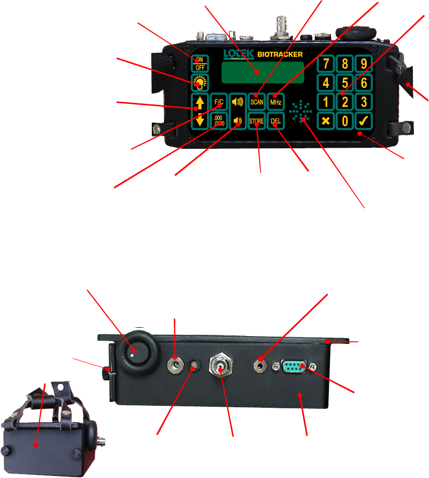
Location of Inputs, Outputs and Controls
Liquid Crystal Display (LCD)
Top row: signal strength and low battery symbol
Bottom row: frequency - channel - gain - mode
On/off
Switch
LCD Back-light
Timed auto switch off
Frequency/Channel
mode switch
Current mode is shown in
bottom right of LCD (after
gain level)
Tuning Step
Switches between
0.1 and 1 kHz
Digital Gain
up/down keys
Gain level is
displayed on bottom
right of LCD
Membrane Keypad
Completely waterproof.
Keys are domed and click
when pressed
Numeric
Key Pad
Tick and cross
keys are accept
(enter) and
reject (cancel)
Enters Scan
Mode
Stores a
frequency
in memory
(channels)
Delete
Key
Loudspeaker
Fully protected under membrane keypad
Shoulder
Strap
Leather
stirrups and
adjustable
nylon strap
Sets MHz
frequency
Frequency/Channel
up/down keys
Gain Knob
Analogue control
sets gain from
zero to an upper
limit set by the
digital gain keys
Battery Charger and External
Power Socket
The receiver comes with a mains power
supply, but can be charged from any 12V
source (e.g. car battery, lead supplied).
Headphones Socket
Internal speaker is silenced
when headphones are inserted.
Serial Port
(RS232)
For computer control
of receiver functions
Silicone seal on lid
For complete water proofing
Antenna
Connector
(standard BNC)
Diecast
Aluminium
Case
Lightweight and
very robust
Battery
Compartment
Neoprene water
proofing seal.
Knurled nuts to
fasten lid
Charging LED
Flashes red during
charging and steady
green when fully-
charged
End View
Shows battery cover
and shoulder strap
Lotek Biotracker Receiver User’s Manual Page 27
APPENDIX A: ADDITIONAL INFORMATION
This equipment has been tested and found to comply with the limits for a Class B digital
device, pursuant to Part 15 of the FCC Rules. These limits are designed to provide
reasonable protection against harmful interference in a residential installation. This
equipment generates, uses and can radiate radio frequency energy and, if not installed
and used in accordance with the instructions, may cause harmful interference to radio
communications. However, there is no guarantee that interference will not occur in a
particular installation. If this equipment does cause harmful interference to radio or
television reception, which can be determine by turning the equipment off and on, the
user is encouraged to try to correct the interference by one or more of the following
measures:
Reorient or relocate the receiving antenna.
Increase the separation between the equipment and receiver.
Connect the equipment into an outlet on a circuit different from that to which the
receiver is connected.
Consult the dealer or an experienced radio/TV technician for help.
WARNING
Changes or modifications not expressly approved by Lotek Wireless could void the user’s
authority to operate the equipment.
Biotracker Manual BC03 Rev B.doc 10/30/07