Lotek Wireless SRX400158-170 Telemetry Receiver User Manual 586356
Lotek Wireless, Inc Telemetry Receiver 586356
UserManual.wiki
>
Lotek Wireless
>
SRX400158-170 User Manual
>
STR1000 Users manual
Contents
1.
SRX400 Users manual
2.
STR1000 Users manual
STR1000 Users manual
Navigation menu
Upload a User Manual
Namespaces
Wiki Guide
HTML
PDF
Info
Views
User Manual
Discussion / Help
Navigation
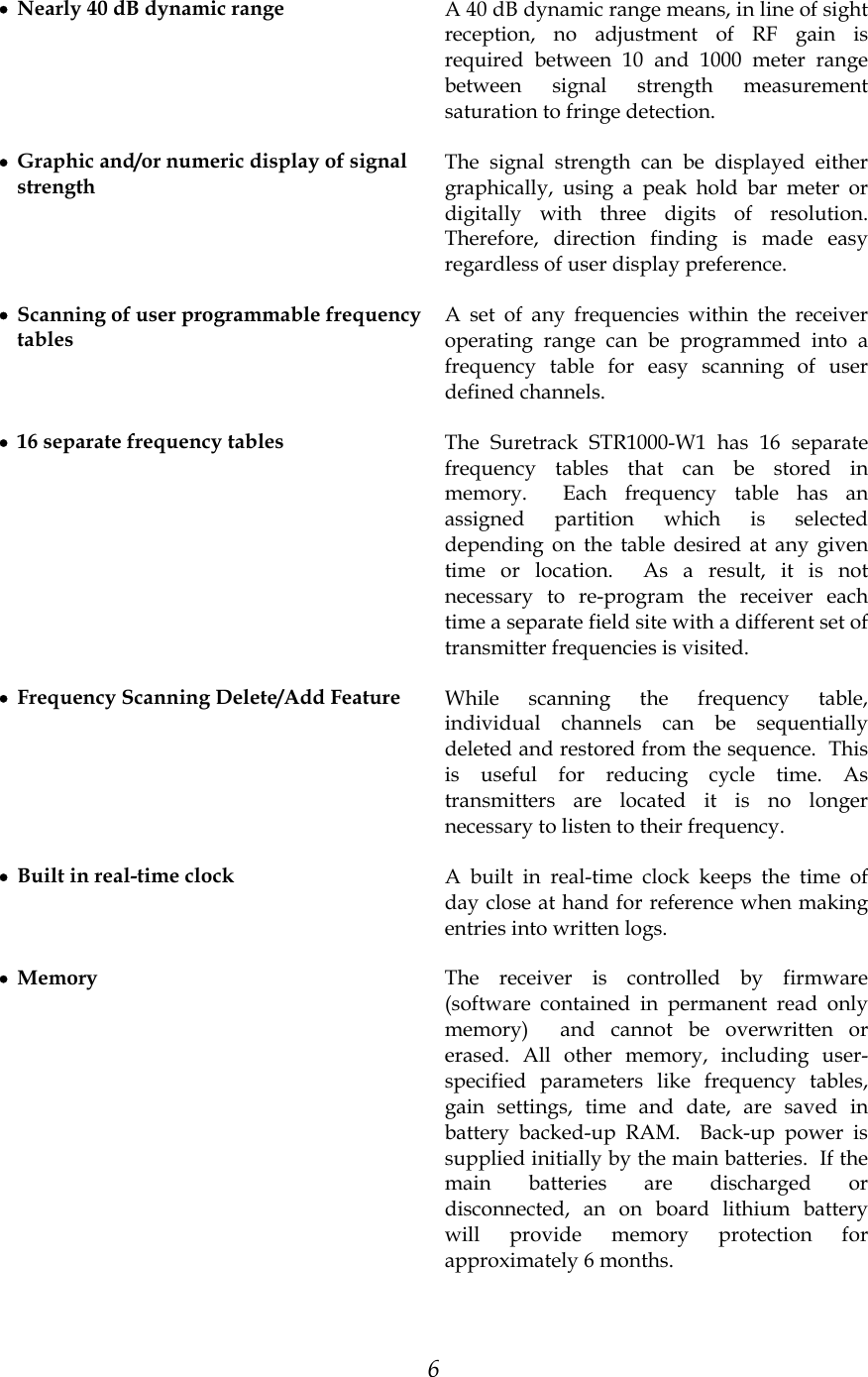
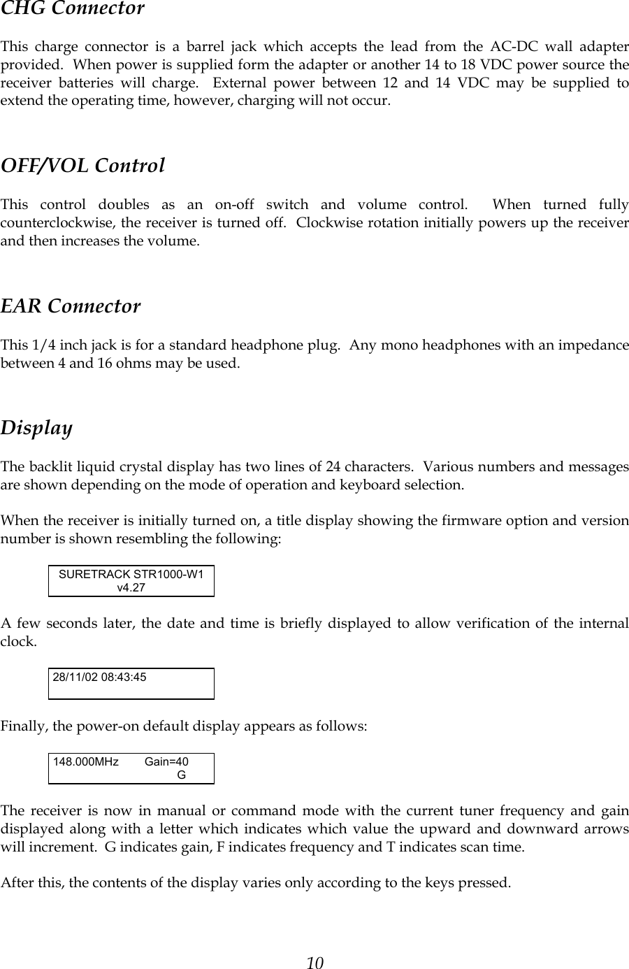
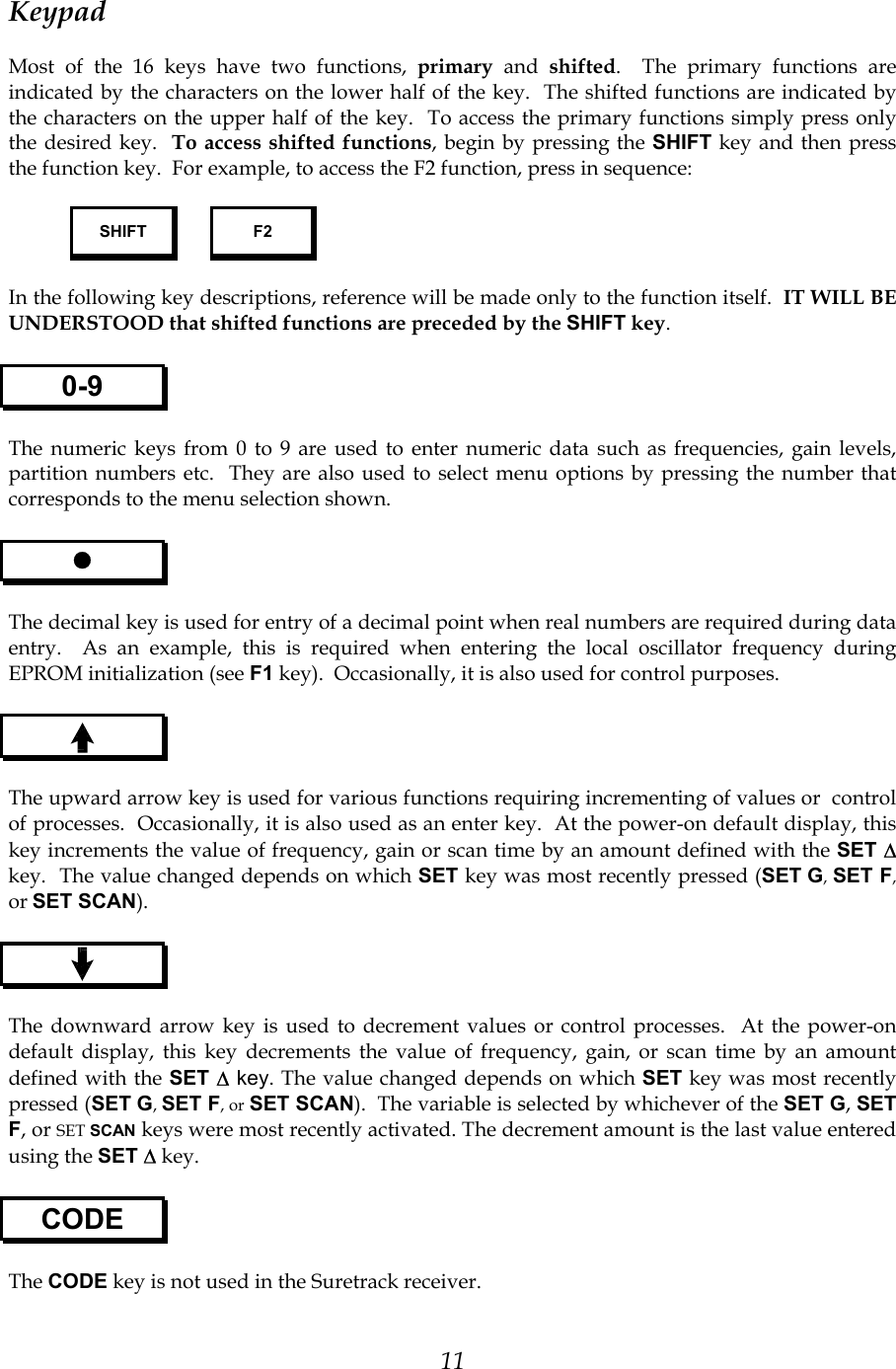
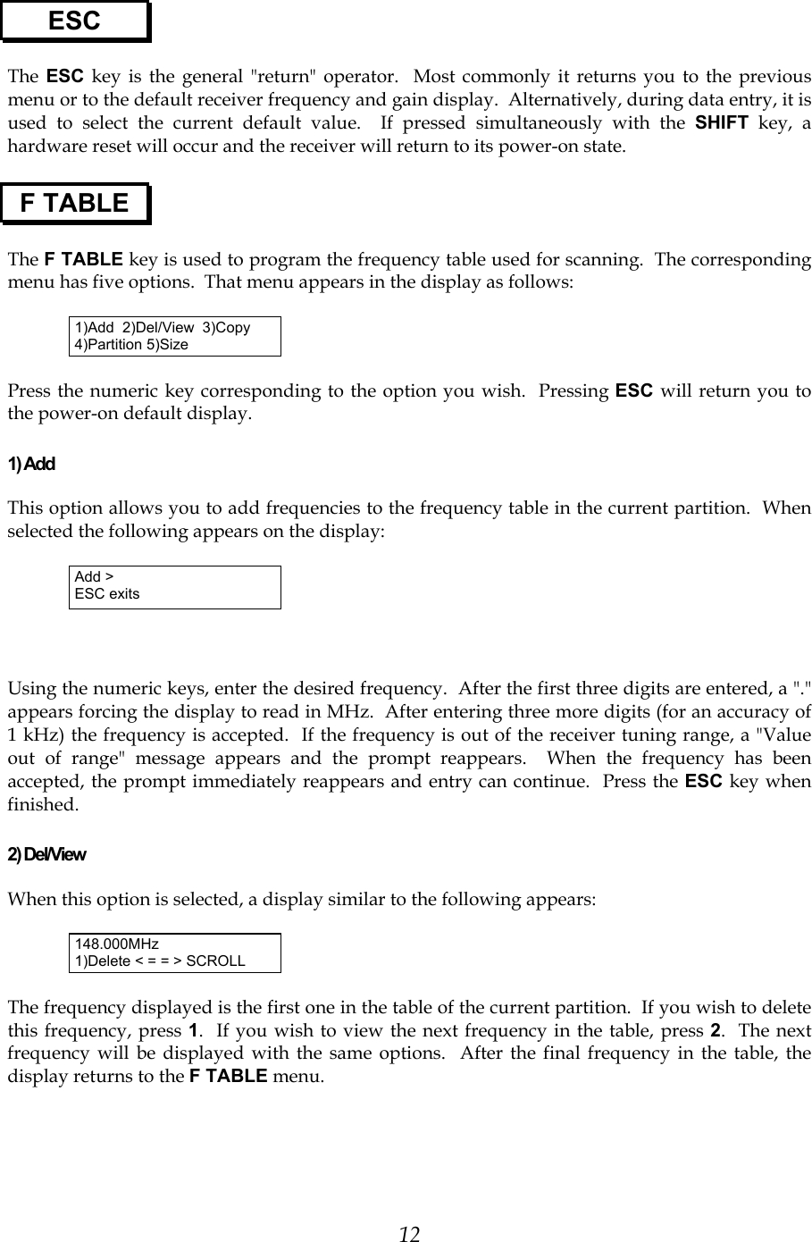
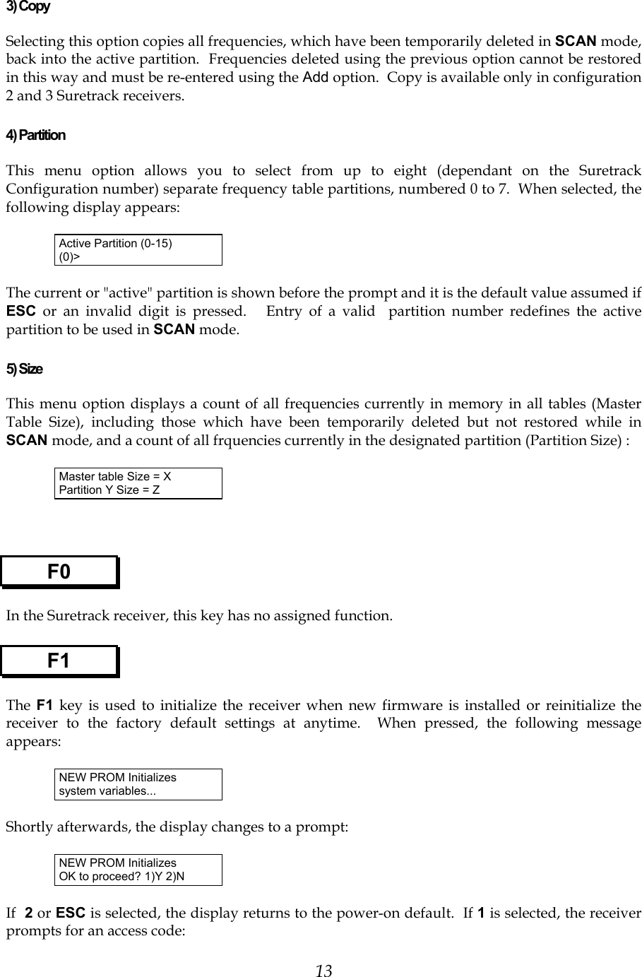
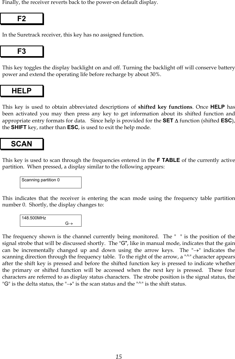
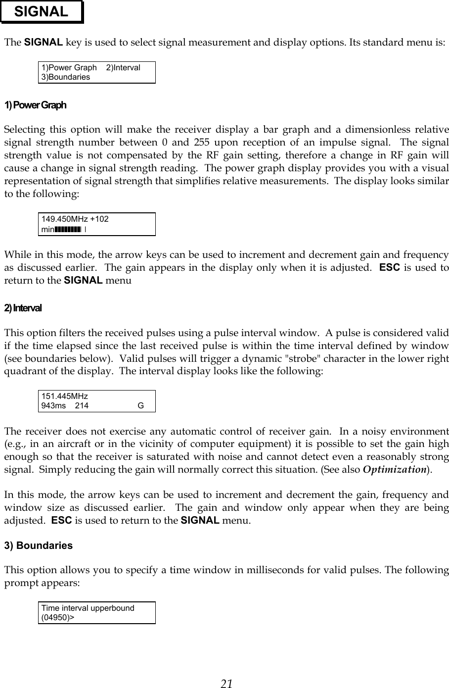
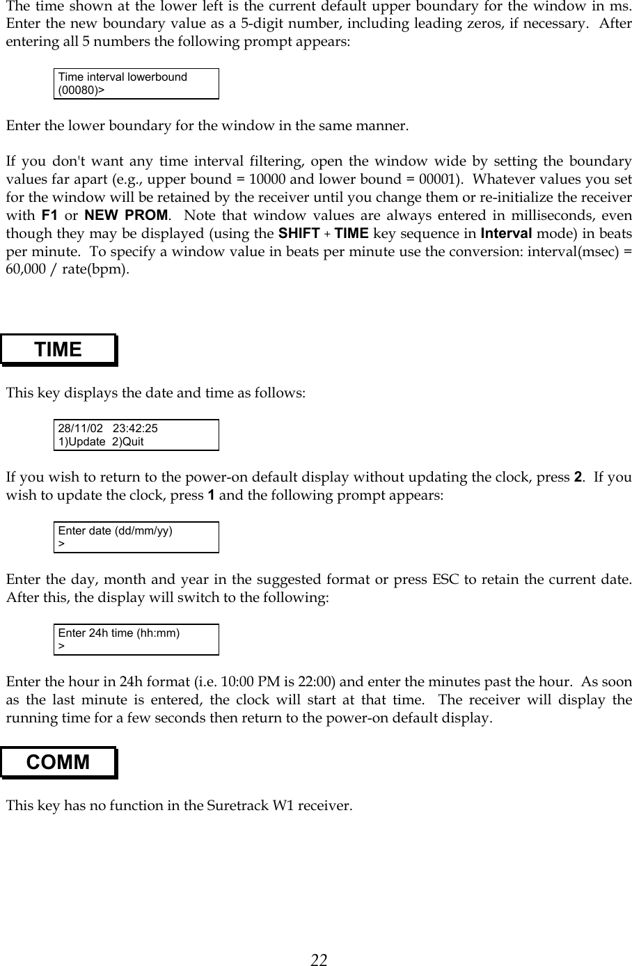
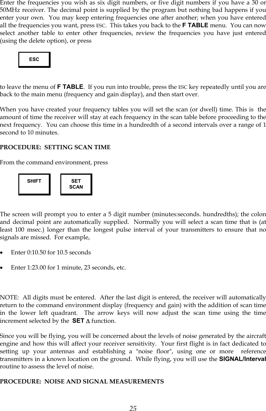
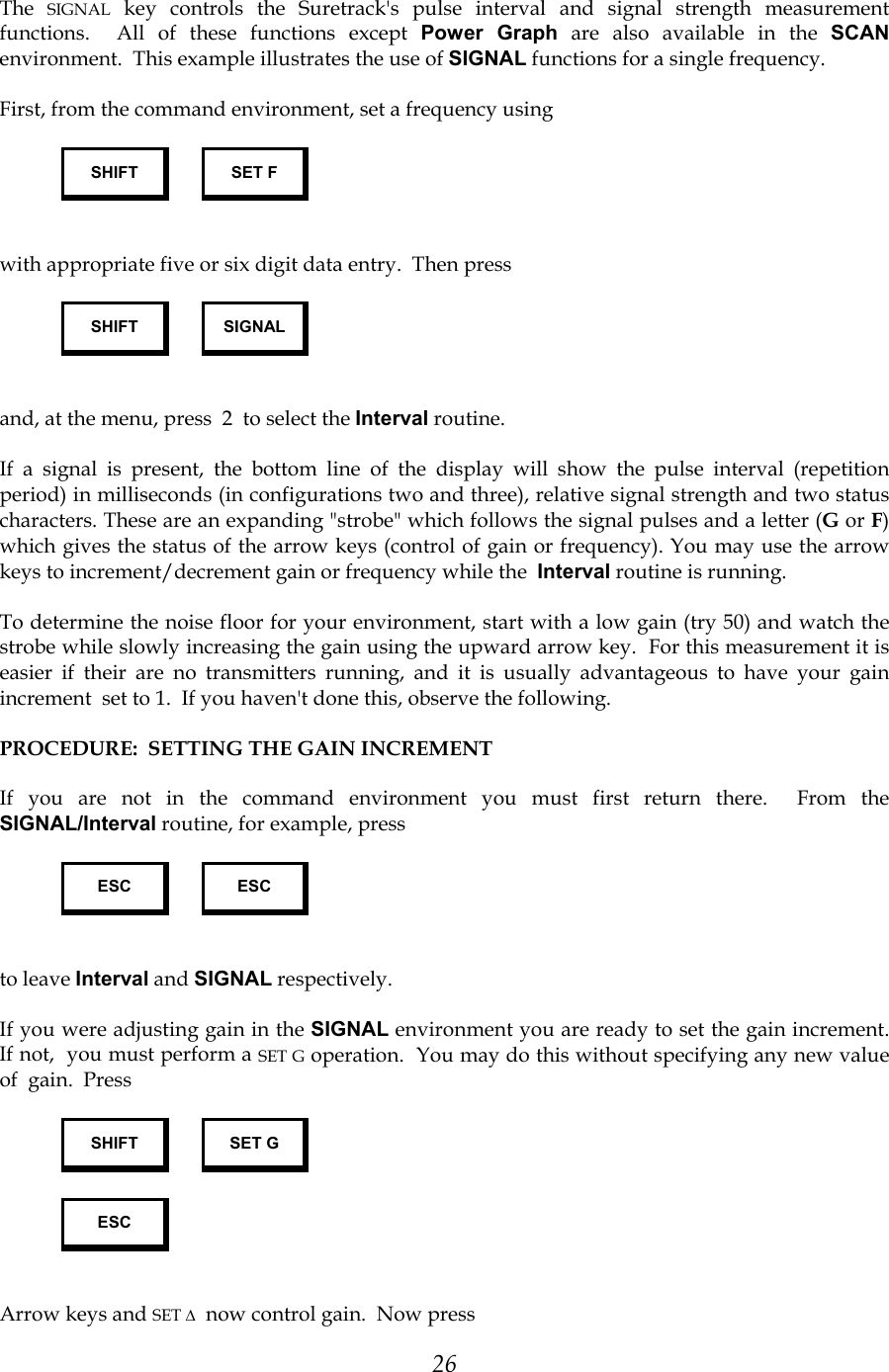
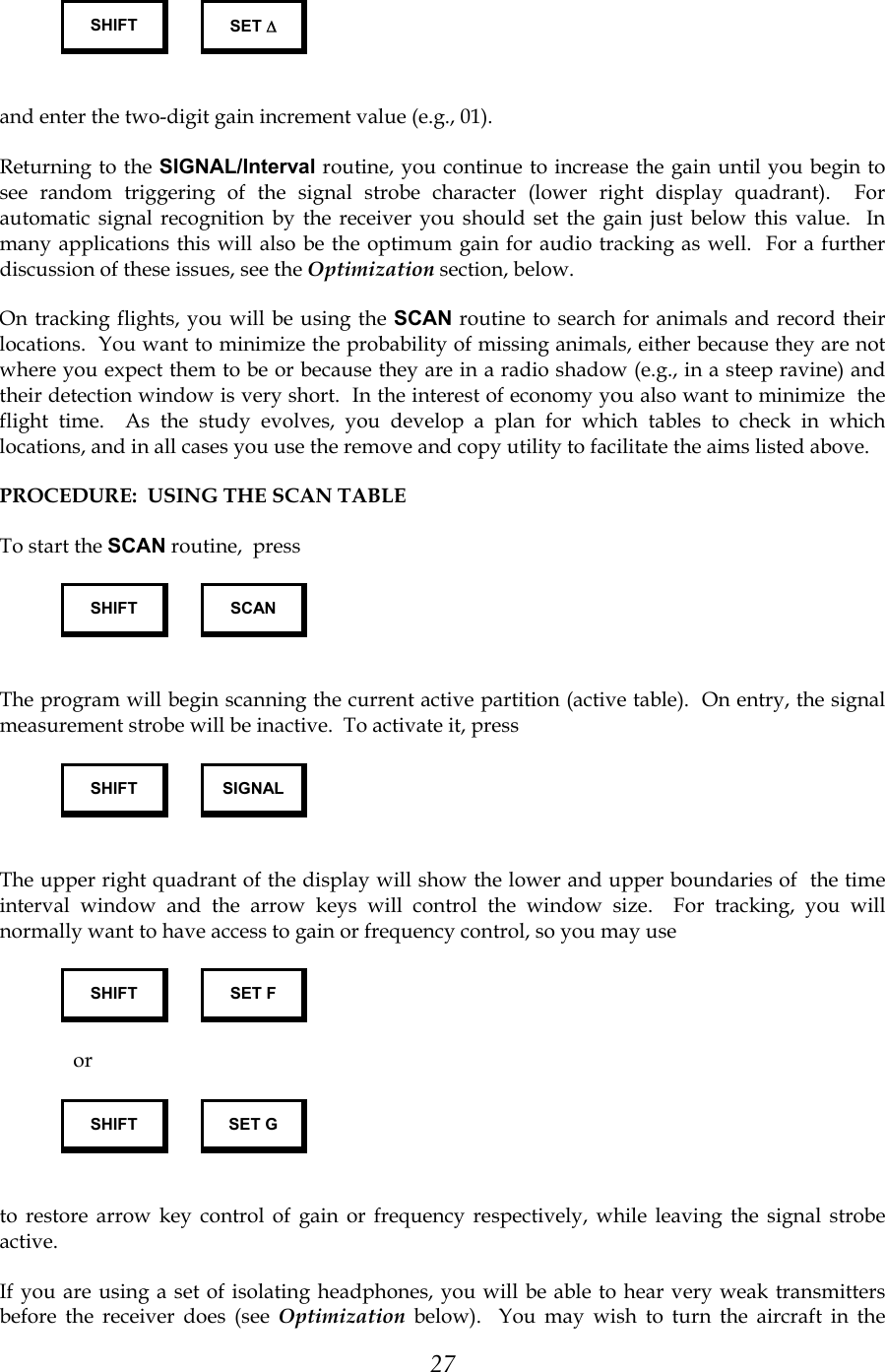
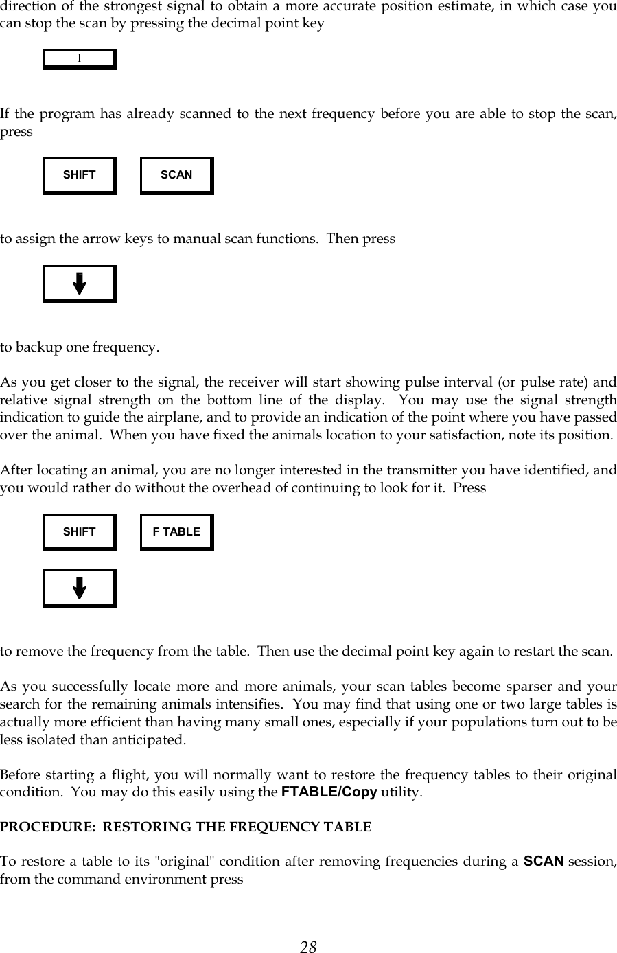
![16 G F → T ← ^ W : Signal Status Delta Status Scan Status Shift Status Figure 1: Display Status Characters After a period of time, the receiver automatically changes to the next frequency in the table. The dwell time on each frequency is governed by the value specified using the SET SCAN key. Scanning continues indefinitely in a cyclical pattern, returning to the first frequency after the last one is scanned. Pulse interval and signal strength information can be displayed while in scan mode by using the key sequence: SHIFT SIGNAL This acts as an on/off toggle. When on, interval measurements in milliseconds(ms) or rate measurements in beats per minute(bpm), are displayed after each transmitter pulse in the lower left corner. To the right of the interval measurement appears the relative signal strength. This value can be as low as 40 for weak signals and as high as 230 for very strong signals. In the signal strobe position, the square place holder, mentioned above, is replaced by a strobe in synchronous with the transmitter pulse. The delta status changes from G to W to indicate that the detection window will be adjusted by the arrow keys. The current window limits are also shown at the top right of the display. As an example, the display might look like this: 149.423MHz [30:5000] 982ms W→ The detection window is a range of pulse intervals or rates that will be recognized by the receiver. Outside of this range, signals will be ignored. The units of measurement, ms or bpm, can be toggled using the key sequence: SHIFT TIME Whether in scan mode or not, the parameter that is incrementally adjusted using the arrow keys can be selected by using one of the following key sequences: SHIFT SET F](https://usermanual.wiki/Lotek-Wireless/SRX400158-170.STR1000-Users-manual/User-Guide-586356-Page-16.png)